EP4273406A1 - Centrifugal fan and washing apparatus provided with same - Google Patents
Centrifugal fan and washing apparatus provided with same Download PDFInfo
- Publication number
- EP4273406A1 EP4273406A1 EP21913912.8A EP21913912A EP4273406A1 EP 4273406 A1 EP4273406 A1 EP 4273406A1 EP 21913912 A EP21913912 A EP 21913912A EP 4273406 A1 EP4273406 A1 EP 4273406A1
- Authority
- EP
- European Patent Office
- Prior art keywords
- volute
- impeller
- stage
- axial
- sidewall
- Prior art date
- Legal status (The legal status is an assumption and is not a legal conclusion. Google has not performed a legal analysis and makes no representation as to the accuracy of the status listed.)
- Pending
Links
- 238000005406 washing Methods 0.000 title claims abstract description 22
- 230000000903 blocking effect Effects 0.000 claims abstract description 14
- 238000001035 drying Methods 0.000 claims description 15
- 239000000243 solution Substances 0.000 description 12
- 238000004519 manufacturing process Methods 0.000 description 7
- 239000000463 material Substances 0.000 description 5
- 230000003014 reinforcing effect Effects 0.000 description 5
- 230000001965 increasing effect Effects 0.000 description 4
- 238000001746 injection moulding Methods 0.000 description 3
- 230000000694 effects Effects 0.000 description 2
- 238000001704 evaporation Methods 0.000 description 2
- 230000008020 evaporation Effects 0.000 description 2
- XLYOFNOQVPJJNP-UHFFFAOYSA-N water Chemical compound O XLYOFNOQVPJJNP-UHFFFAOYSA-N 0.000 description 2
- 238000010521 absorption reaction Methods 0.000 description 1
- 230000004888 barrier function Effects 0.000 description 1
- 238000004891 communication Methods 0.000 description 1
- 238000001816 cooling Methods 0.000 description 1
- 230000002708 enhancing effect Effects 0.000 description 1
- 239000007769 metal material Substances 0.000 description 1
- 238000000034 method Methods 0.000 description 1
- 239000012778 molding material Substances 0.000 description 1
Images




Classifications
-
- F—MECHANICAL ENGINEERING; LIGHTING; HEATING; WEAPONS; BLASTING
- F04—POSITIVE - DISPLACEMENT MACHINES FOR LIQUIDS; PUMPS FOR LIQUIDS OR ELASTIC FLUIDS
- F04D—NON-POSITIVE-DISPLACEMENT PUMPS
- F04D25/00—Pumping installations or systems
- F04D25/02—Units comprising pumps and their driving means
- F04D25/08—Units comprising pumps and their driving means the working fluid being air, e.g. for ventilation
-
- D—TEXTILES; PAPER
- D06—TREATMENT OF TEXTILES OR THE LIKE; LAUNDERING; FLEXIBLE MATERIALS NOT OTHERWISE PROVIDED FOR
- D06F—LAUNDERING, DRYING, IRONING, PRESSING OR FOLDING TEXTILE ARTICLES
- D06F25/00—Washing machines with receptacles, e.g. perforated, having a rotary movement, e.g. oscillatory movement, the receptacle serving both for washing and for centrifugally separating water from the laundry and having further drying means, e.g. using hot air
-
- D—TEXTILES; PAPER
- D06—TREATMENT OF TEXTILES OR THE LIKE; LAUNDERING; FLEXIBLE MATERIALS NOT OTHERWISE PROVIDED FOR
- D06F—LAUNDERING, DRYING, IRONING, PRESSING OR FOLDING TEXTILE ARTICLES
- D06F58/00—Domestic laundry dryers
- D06F58/20—General details of domestic laundry dryers
-
- F—MECHANICAL ENGINEERING; LIGHTING; HEATING; WEAPONS; BLASTING
- F04—POSITIVE - DISPLACEMENT MACHINES FOR LIQUIDS; PUMPS FOR LIQUIDS OR ELASTIC FLUIDS
- F04D—NON-POSITIVE-DISPLACEMENT PUMPS
- F04D17/00—Radial-flow pumps, e.g. centrifugal pumps; Helico-centrifugal pumps
- F04D17/08—Centrifugal pumps
- F04D17/16—Centrifugal pumps for displacing without appreciable compression
-
- F—MECHANICAL ENGINEERING; LIGHTING; HEATING; WEAPONS; BLASTING
- F04—POSITIVE - DISPLACEMENT MACHINES FOR LIQUIDS; PUMPS FOR LIQUIDS OR ELASTIC FLUIDS
- F04D—NON-POSITIVE-DISPLACEMENT PUMPS
- F04D29/00—Details, component parts, or accessories
- F04D29/08—Sealings
- F04D29/16—Sealings between pressure and suction sides
- F04D29/161—Sealings between pressure and suction sides especially adapted for elastic fluid pumps
- F04D29/162—Sealings between pressure and suction sides especially adapted for elastic fluid pumps of a centrifugal flow wheel
-
- F—MECHANICAL ENGINEERING; LIGHTING; HEATING; WEAPONS; BLASTING
- F04—POSITIVE - DISPLACEMENT MACHINES FOR LIQUIDS; PUMPS FOR LIQUIDS OR ELASTIC FLUIDS
- F04D—NON-POSITIVE-DISPLACEMENT PUMPS
- F04D29/00—Details, component parts, or accessories
- F04D29/26—Rotors specially for elastic fluids
- F04D29/28—Rotors specially for elastic fluids for centrifugal or helico-centrifugal pumps for radial-flow or helico-centrifugal pumps
- F04D29/281—Rotors specially for elastic fluids for centrifugal or helico-centrifugal pumps for radial-flow or helico-centrifugal pumps for fans or blowers
- F04D29/282—Rotors specially for elastic fluids for centrifugal or helico-centrifugal pumps for radial-flow or helico-centrifugal pumps for fans or blowers the leading edge of each vane being substantially parallel to the rotation axis
-
- F—MECHANICAL ENGINEERING; LIGHTING; HEATING; WEAPONS; BLASTING
- F04—POSITIVE - DISPLACEMENT MACHINES FOR LIQUIDS; PUMPS FOR LIQUIDS OR ELASTIC FLUIDS
- F04D—NON-POSITIVE-DISPLACEMENT PUMPS
- F04D29/00—Details, component parts, or accessories
- F04D29/40—Casings; Connections of working fluid
- F04D29/42—Casings; Connections of working fluid for radial or helico-centrifugal pumps
- F04D29/4206—Casings; Connections of working fluid for radial or helico-centrifugal pumps especially adapted for elastic fluid pumps
- F04D29/4213—Casings; Connections of working fluid for radial or helico-centrifugal pumps especially adapted for elastic fluid pumps suction ports
-
- F—MECHANICAL ENGINEERING; LIGHTING; HEATING; WEAPONS; BLASTING
- F04—POSITIVE - DISPLACEMENT MACHINES FOR LIQUIDS; PUMPS FOR LIQUIDS OR ELASTIC FLUIDS
- F04D—NON-POSITIVE-DISPLACEMENT PUMPS
- F04D29/00—Details, component parts, or accessories
- F04D29/40—Casings; Connections of working fluid
- F04D29/42—Casings; Connections of working fluid for radial or helico-centrifugal pumps
- F04D29/4206—Casings; Connections of working fluid for radial or helico-centrifugal pumps especially adapted for elastic fluid pumps
- F04D29/4226—Fan casings
-
- F—MECHANICAL ENGINEERING; LIGHTING; HEATING; WEAPONS; BLASTING
- F04—POSITIVE - DISPLACEMENT MACHINES FOR LIQUIDS; PUMPS FOR LIQUIDS OR ELASTIC FLUIDS
- F04D—NON-POSITIVE-DISPLACEMENT PUMPS
- F04D29/00—Details, component parts, or accessories
- F04D29/40—Casings; Connections of working fluid
- F04D29/42—Casings; Connections of working fluid for radial or helico-centrifugal pumps
- F04D29/44—Fluid-guiding means, e.g. diffusers
- F04D29/441—Fluid-guiding means, e.g. diffusers especially adapted for elastic fluid pumps
-
- F—MECHANICAL ENGINEERING; LIGHTING; HEATING; WEAPONS; BLASTING
- F05—INDEXING SCHEMES RELATING TO ENGINES OR PUMPS IN VARIOUS SUBCLASSES OF CLASSES F01-F04
- F05D—INDEXING SCHEME FOR ASPECTS RELATING TO NON-POSITIVE-DISPLACEMENT MACHINES OR ENGINES, GAS-TURBINES OR JET-PROPULSION PLANTS
- F05D2250/00—Geometry
- F05D2250/50—Inlet or outlet
- F05D2250/51—Inlet
Definitions
- the present disclosure relates to a washing apparatus, and specifically to a centrifugal fan and a washing apparatus having the same.
- Some existing washing apparatuses such as drum-type heat pump washing-drying integrated machines, all have a drying system, which can provide a drying function for wet articles (such as clothing) that have been washed.
- the drying system typically includes a fan, a heater, and an evaporation device or another device that can cool hot and humid air.
- the fan blows hot air heated by the heater into a washing cylinder.
- the hot air is mixed with wet clothing in the washing cylinder to generate a hot and humid airflow.
- the hot and humid airflow is then discharged from the washing cylinder and enters a return air channel.
- the hot and humid airflow is cooled through heat absorption of the evaporation device, and water vapor contained therein is condensed to become water droplets, thereby achieving the purpose of dehumidifying and cooling the airflow.
- the dehumidified airflow is sucked in again by the fan and undergoes a new cycle.
- An air supply volume of the fan is a key factor that affects a drying efficiency of the washing apparatus.
- the commonly used form of the fan is a centrifugal fan.
- a centrifugal fan includes a volute and an impeller rotatably arranged in the volute.
- An air inlet is provided on an axial air inflow sidewall of the volute, and an air inlet is also provided on an axial air inflow sidewall of the impeller.
- the two air inlets are aligned with each other, and the axial air inflow sidewall of the volute is opposite to the axial air inflow sidewall of the impeller.
- a centrifugal fan which includes: a volute, which has an axial air inflow sidewall of the volute, a volute air inlet being provided on the axial air inflow sidewall of the volute; and an impeller, which is configured to be rotatably arranged in the volute and has an axial air inflow sidewall of the impeller; a first axial gap is formed between the axial air inflow sidewall of the impeller and the axial air inflow sidewall of the volute, and an impeller air inlet that can be aligned with the volute air inlet is provided on the axial air inflow sidewall of the impeller; an outer annular protrusion extending outward from the axial air inflow sidewall of the impeller is arranged around the impeller air inlet, and an inner annular protrusion extending inward from the axial air inflow sidewall of the vol
- an inner annular protrusion extending inward from the axial air inflow sidewall of the volute is arranged on the axial air inflow sidewall of the volute around the volute air inlet
- an outer annular protrusion extending outward from the axial air inflow sidewall of the impeller is arranged on the axial air inflow sidewall of the impeller around the impeller air inlet.
- the inner annular protrusion and the outer annular protrusion are opposite to each other and are spaced apart by a second axial gap, which is smaller than a first axial gap between the axial air inflow sidewall of the volute and the axial air inflow sidewall of the impeller. It is obvious that due to the blocking by the inner annular protrusion and the outer annular protrusion, as well as the narrowing of flow channel, a resistance to the wind flowing through the second axial gap is significantly larger than a resistance to the wind flowing through the first axial gap. Therefore, the outer annular protrusion and the inner annular protrusion together can play a role of blocking the wind from flowing into the impeller air inlet from the first axial gap. In other words, the outer annular protrusion and the inner annular protrusion together form an internal wind circulation blocking structure, which can substantially eliminate the phenomenon of internal wind circulation and therefore increase the effective supply air volume of the centrifugal fan.
- the outer annular protrusion includes a multi-stage outer annular step
- the inner annular protrusion includes a multi-stage inner annular step corresponding to the multi-stage outer annular step.
- the multi-stage steps extending axially on the fan form a flow channel with multiple substantially right angle turns, thereby achieving multi-stage blocking of the wind. Therefore, as the number of the stages of steps increases, the effect of the internal wind circulation blocking structure becomes better.
- inner annular grooves are formed between adjacent inner annular steps of the multi-stage inner annular step.
- the multi-stage outer annular step includes a three-stage outer annular step
- the multi-stage inner annular step includes a three-stage inner annular step.
- the three-stage outer annular step and the three-stage inner annular step together form three wind barriers that can block internal wind circulation, and the manufacturing process of the entire fan is also relatively simple.
- a multi-stage volute outer annular step extending outward from the axial air inflow sidewall of the volute is arranged around the volute air inlet, and each stage of the volute outer annular step and the corresponding stage of the inner annular step extend axially in opposite directions.
- the volute outer annular step is designed to reduce the weight of the volute, while also saving the amount of material used for the volute.
- the outer annular protrusion and the inner annular protrusion are configured to share a centerline with the volute air inlet and the impeller air inlet.
- the use of the same centerline makes the manufacturing of the centrifugal fan simpler and more convenient.
- the outer annular protrusion is positioned close to the impeller air inlet, and the inner annular protrusion is positioned close to the volute air inlet.
- Manufacturing the inner annular protrusion close to the volute air inlet and the outer annular protrusion close to the impeller air inlet substantially does not require changing the sizes of the volute and the impeller, but enables the centrifugal fan to have a function of blocking the internal wind circulation.
- the impeller is disc-shaped, a plurality of evenly spaced radial impeller air outlets are formed on an outer circumference of the impeller, and the radial impeller air outlets are communicated with each other to form an annular exhaust chamber inside the volute.
- the disc-shaped impeller is not only small in volume, but also is easy to produce.
- the volute further includes a motor mounting wall opposite to the axial air inflow sidewall of the volute, and the motor mounting wall is provided with a motor shaft hole and a plurality of motor mounting holes arranged circumferentially around the motor shaft hole. These motor mounting holes facilitate fixing the motor to the volute.
- the present disclosure also provides a washing apparatus, which is provided with a drying system, and the drying system includes the centrifugal fan as described in any of the above.
- a drying air volume of the washing apparatus can be increased, thereby improving the drying efficiency of the washing apparatus.
- connection may be a fixed connection, or may also be a detachable connection, or an integral connection; it may be a direct connection, or an indirect connection implemented through an intermediate medium, or it may be internal communication between two elements.
- connection may be a fixed connection, or may also be a detachable connection, or an integral connection; it may be a direct connection, or an indirect connection implemented through an intermediate medium, or it may be internal communication between two elements.
- the centrifugal fan 1 includes: a volute 11, which has an axial air inflow sidewall 112 of the volute, a volute air inlet 111 being provided on the axial air inflow sidewall 112 of the volute; and an impeller 12, which is configured to be rotatably arranged in the volute 11 and has an axial air inflow sidewall 122 of the impeller; a first axial gap 14 is formed between the axial air inflow sidewall 122 of the impeller and the axial air inflow sidewall 112 of the volute, and an impeller air inlet 121 that can be aligned with the volute air inlet 111 is provided on the axial air inflow sidewall 122 of the impeller; an outer annular protrusion 132 extending outward from the axial air inflow sidewall 122 of the impeller is arranged around the impeller air inlet 121, and an inner annular
- an airflow b entering the first axial gap between the axial air inflow sidewall 112 of the volute and the axial air inflow sidewall 122 of the impeller is blocked when encountering the outer annular protrusion 132 and the inner annular protrusion 131 protruding into the first axial gap 14 from both sides, and a width D2 of the second axial gap 15 between the outer annular protrusion 132 and the inner annular protrusion 131 is significantly smaller than a width D1 of the first axial gap 14, so that a resistance to the airflow b flowing through the second axial gap 15 is significantly increased, ultimately forcing the airflow b to change its direction and flow toward an annular exhaust chamber 113 of the volute 11.
- the second axial gap 15 may have multiple turns to further increase a resistance to the wind passing therethrough.
- FIG. 2 is a partial cross-sectional schematic perspective view of an embodiment of the centrifugal fan of the present disclosure
- FIG. 3 is a partial cross-sectional schematic plan view of the embodiment of the centrifugal fan of the present disclosure.
- the centrifugal fan 1 of the present disclosure includes the volute 11 and the impeller 12.
- the impeller 12 is configured to be rotatably arranged in the volute 11.
- the centrifugal fan 1 further includes a motor (not shown in the drawings).
- the impeller 12 is fixedly connected with a drive shaft of the motor. When the centrifugal fan 1 is working, the drive shaft (not shown in the drawings) of the motor drives the impeller 12 to rotate inside the volute 11.
- Wind is drawn into the impeller 12 in a direction indicated by an arrow a (also referred to as an axial direction), then is discharged into the annular exhaust chamber 113 of the volute 11 in a radial flow direction r, and finally is blown out from a volute air outlet 118 (see FIG. 4 ).
- Appropriate gaps are required to be left between the impeller 12 and the volute 11 to allow the impeller 12 to rotate inside the volute 11 without being impeded.
- the gaps include axial gaps located on two opposite axial sides of the impeller 12 (in a direction of centerline c) and a radial gap located on an outer circumference of the impeller 12, such as the first axial gap 14 located on the air inflow side.
- the first axial gap 14 has a first axial width D1.
- both the impeller 12 and the volute 11 can be made of appropriate injection molding materials.
- the impeller 12 can be manufactured through one-time injection molding process. The manufactured impeller 12 is placed into a mold cavity used to manufacture the volute 11, and then the one-time injection molding process is used to not only manufacture the volute 11, but also assemble the volute 11 and the impeller 12 together.
- the impeller 12 and the volute 11 can also be made of other suitable metal materials and through other suitable processes.
- FIG. 4 is a schematic perspective view of a part of an embodiment of the volute of the centrifugal fan of the present disclosure
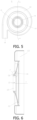
- FIG. 5 is a schematic plan view of a part of the embodiment of the volute of the centrifugal fan of the present disclosure
- FIG. 6 is a schematic cross-sectional view of a part of the embodiment of the volute of the centrifugal fan of the present disclosure taken along E-E section line in FIG. 5
- FIG. 7 is a partially enlarged view of a portion F of a part of the embodiment of the volute of the centrifugal fan of the present disclosure shown in FIG. 6 .
- FIGS. 1 As shown in FIGS.
- the volute 11 includes the axial air inflow sidewall 112 of the volute and an opposite motor mounting wall 114.
- the axial air inflow sidewall 112 of the volute and the motor mounting wall 114 together enclose an impeller chamber (not labelled in the drawings) that can accommodate the impeller 12.
- the annular exhaust chamber 113 surrounding the impeller chamber is formed on a radial outer circumference of the impeller chamber.
- the annular exhaust chamber 113 is communicated with the impeller chamber to receive the airflow discharged from the impeller 12.
- the annular exhaust chamber 113 has a substantially rectangular cross section, and four corners of the cross section are each rounded.
- a width of the cross section of the annular exhaust chamber 113 is larger than a width of the cross section of the impeller chamber.
- the volute air outlet 118 is provided in a circumferential direction of the annular exhaust chamber 113, and the annular exhaust chamber 113 is directly communicated with the volute air outlet 118 so as to blow wind outward from the volute air outlet 118.
- the motor mounting wall 114 of the volute 11 is a thin wall with a predetermined thickness.
- the predetermined thickness can be determined according to actual needs.
- a motor shaft hole 141 is provided in the center of the motor mounting wall 114 to allow the drive shaft of the motor to rotatably pass through.
- a connection slot (not labelled in the drawings) for accommodating a drive shaft end of the motor (i.e., an end from which the drive shaft extends outward) is provided on an outside surface of the motor mounting wall 114 (which is the right side surface based on the orientation shown in FIGS. 2 and 3 ).
- the connection slot is enclosed by a circumferential end wall 142.
- the circumferential end wall 142 extends outward perpendicularly by a first predetermined height from the outside surface of the motor mounting wall 114 by taking the motor shaft hole 141 as center.
- the first predetermined height can be determined according to actual needs.
- a first circumferential rib wall 143 and a second circumferential rib wall 144 are further provided on the outside surface of the motor mounting wall 114.
- the first circumferential rib wall 143 and the second circumferential rib wall 144 both surround the circumferential end wall 142 and are concentric with the circumferential end wall 142.
- the first circumferential rib wall 143 is located between the circumferential end wall 142 and the second circumferential rib wall 144, preferably in a middle position between the circumferential end wall 142 and the second circumferential rib wall 144.
- the first circumferential rib wall 143 and the second circumferential rib wall 144 extend outward perpendicularly by a second predetermined height and a third predetermined height respectively from the outside surface of the motor mounting wall 114.
- the second predetermined height and the third predetermined height can both be determined according to actual needs.
- the first circumferential rib wall 143 is substantially flush with the circumferential end wall 142, while the second circumferential rib wall 144 extends outward beyond the first circumferential rib wall 143 and the circumferential end wall 142. As shown in FIG.
- a plurality of first radial ribs 145 are provided between the first circumferential rib wall 143 and the circumferential end wall 142.
- Each of the first radial ribs 145 extends radially from the circumferential end wall 142 to the first circumferential rib wall 143.
- Adjacent first radial ribs 145 are spaced apart by the same distance. Alternatively, uneven spacing can be formed between adjacent first radial ribs 145 according to actual needs.
- a plurality of second radial ribs 146 are provided between the first circumferential rib wall 143 and the second circumferential rib wall 144.
- Each of the second radial ribs 146 extends radially from the first circumferential rib wall 143 to the second circumferential rib wall 144. Adjacent second radial ribs 146 are spaced apart by the same distance. Alternatively, uneven spacing can be formed between adjacent second radial ribs 146 according to actual needs.
- the first circumferential rib wall 143, the second circumferential rib wall 144, the first radial ribs 145 and the second radial ribs 146 together can enhance the strength of the motor mounting wall 114.
- connection columns (not labelled in the drawings) spaced apart from each other are provided along the second circumferential rib wall 144.
- a motor connection hole 147 is provided on each of the connection columns.
- the motor can be fixed to the volute 11 through these motor connection holes 147.
- the connection columns can be separated from the second circumferential rib wall 144, or the second circumferential rib wall 144 can be cancelled.
- a plurality of third radial ribs 148 are provided between the second circumferential rib wall 144 and the sidewall forming the annular exhaust chamber 113.
- Each of the third radial ribs 148 extends from the second circumferential rib wall 144 to the sidewall forming the annular exhaust chamber 113. Adjacent third radial ribs 148 are spaced apart by the same distance. Alternatively, uneven spacing can be formed between adjacent third radial ribs 148 according to actual needs. The third radial ribs 148 can further enhance the strength of the volute 11.
- the volute air inlet 111 is arranged in the center of the axial air inflow sidewall 112 of the volute.
- the volute air inlet 111 is enclosed by a circumferential wall 115 of the volute air inlet around the centerline c.
- the axial air inflow sidewall 112 of the volute extends substantially radially from the circumferential wall 115 of the volute air inlet to the sidewall forming the annular exhaust chamber 113.
- an inner annular protrusion 131 extending inward (to the right based on the orientation shown in FIG. 6 ) from the axial air inflow sidewall 112 of the volute is arranged around the volute air inlet 111.
- the inner annular protrusion 131 shares the centerline c with the volute air inlet 111, which facilitates manufacturing of the volute 11.
- the center of the inner annular protrusion 131 can deviate from the center of the volute air inlet 111.
- the inner annular protrusion 131 is a three-stage inner annular step near the volute air inlet 111: a first-stage inner annular step 131a, a second-stage inner annular step 131b, and a third-stage inner annular step 131c.
- the first-stage inner annular step 131a is adjacent to and surrounds the circumferential wall 115 of the volute air inlet.
- a first inner annular groove 133a is formed between the first-stage inner annular step 131a and the circumferential wall 115 of the volute air inlet.
- the circumferential wall 115 of the volute air inlet extends inward beyond the first-stage inner annular step 131a in the direction of the centerline c.
- the second-stage inner annular step 131b is adjacent to and surrounds the first-stage inner annular step 131a.
- the second-stage inner annular step 131b extends inward beyond the first-stage inner annular step 131a in the direction of the centerline c.
- a second inner annular groove 133b is formed between the second-stage inner annular step 131b and the first-stage inner annular step 131a.
- the third-stage inner annular step 131c is adjacent to and surrounds the second-stage inner annular step 131b.
- the third-stage inner annular step 131c extends inward beyond the second-stage inner annular step 131b in the direction of the centerline c.
- a third inner annular groove 133c is formed between the third-stage inner annular step 131c and the second-stage inner annular step 131b.
- the first inner annular groove 133a, the second inner annular groove 133b and the third inner annular groove 133c all belong to the inner annular groove 133c.
- the inner annular protrusion 131 may be a one-stage, two-stage or more-than-three-stage step.
- the inner annular grooves can be cancelled between adjacent steps.
- the inner annular protrusion 131 can be other suitable forms of protrusion such as ripples to block wind.
- the inner annular protrusion 131 can be positioned away from the volute air inlet 111, such as near a middle portion of the inner side of the axial air inflow sidewall 112 of the volute.
- a volute outer annular step 116 is arranged around the volute air inlet 111 on the outer side of the axial air inflow sidewall 112 of the volute, so as to maintain a relatively thin wall and a lighter weight of the axial air inflow sidewall 112 of the volute.
- the volute outer annular step 116 includes a first-stage volute outer annular step 116a, a second-stage volute outer annular step 116b, and a third-stage volute outer annular step 116c.
- the first-stage volute outer annular step 116a is adjacent to and surrounds the circumferential wall 115 of the volute air inlet. On the outer side of the axial air inflow sidewall 112 of the volute, the circumferential wall 115 of the volute air inlet extends outward beyond the first-stage volute outer annular step 116a in the direction of the centerline c.
- the first-stage volute outer annular step 116a and the first-stage inner annular step 131a are aligned with each other in the direction of the centerline c and extend in opposite directions.
- the second-stage volute outer annular step 116b is adjacent to and surrounds the first-stage volute outer annular step 116a.
- the first-stage volute outer annular step 116a extends outward beyond the second-stage volute outer annular step 116b in the direction of the centerline c.
- the second-stage volute outer annular step 116b and the second-stage inner annular step 131b are aligned with each other in the direction of the centerline c and extend in opposite directions.
- the third-stage volute outer annular step 116c is adjacent to and surrounds the second-stage volute outer annular step 116b.
- the second-stage volute outer annular step 116b extends outward beyond the third-stage volute outer annular step 116c in the direction of the centerline c.
- the third-stage volute outer annular step 116c and the third-stage inner annular step 131c are aligned with each other in the direction of the centerline c and extend in opposite directions.
- the volute outer annular step 116 may be a one-stage, two-stage or more-than-three-stage step.
- the design of stepped protrusion can be cancelled on the outer side of the axial air inflow sidewall 112 of the volute.
- a plurality of reinforcing ribs 117 are provided on the outer side of the axial air inflow sidewall 112 of the volute.
- Each of the reinforcing ribs 117 extends radially outward from the outer circumference of the volute outer annular step 116 to the sidewall forming the annular exhaust chamber 113.
- Adjacent reinforcing ribs 117 have the same circumferential distance therebetween. Alternatively, according to actual needs, the circumferential distance between adjacent reinforcing ribs 117 may also be different.
- FIG. 8 is a schematic perspective view of an embodiment of the impeller of the centrifugal fan of the present disclosure
- FIG. 9 is a schematic front view of the embodiment of the impeller of the centrifugal fan of the present disclosure
- FIG. 10 is a right side view of the embodiment of the impeller of the centrifugal fan of the present disclosure
- FIG. 11 is a partially enlarged view of a portion G of the embodiment of the impeller of the centrifugal fan of the present disclosure shown in FIG. 10 .
- the impeller 12 is a substantially disc-shaped impeller.
- the impeller 12 has the axial air inflow sidewall 122 of the impeller, a blade bottom wall 124, and a plurality of evenly spaced blades 123.
- each of the blades 123 is formed into one piece with the blade bottom wall 124, and extends perpendicularly from the blade bottom wall 124 toward the axial air inflow sidewall 122 of the impeller in the direction of the centerline c.
- Each of the blades 123 is also formed into one piece with the axial air inflow sidewall 122 of the impeller on a portion near the outer circumference of the impeller 12. However, on a portion near the center of the impeller 12, a predetermined gap is formed between each of the blades 123 and the axial air inflow sidewall 122 of the impeller to allow wind to evenly enter all the gaps between adjacent blades. Referring to FIGS.
- a central shaft hub 126 is provided in the center of the blade bottom wall 124.
- the central shaft hub 126 is a substantially cylindrical body around the centerline c.
- the central shaft hub 126 is formed into one piece with the blade bottom wall 124, and extends perpendicularly by a predetermined height from the blade bottom wall 124 toward the axial air inflow sidewall 122 of the impeller along the centerline c.
- the predetermined height should be lower than a maximum height of each blade 123.
- a central shaft hole 127 centered on the centerline c is formed in the center of the central shaft hub 126. The central shaft hole 127 penetrates through the entire central shaft hub 126.
- the central shaft hole 127 is aligned with the motor shaft hole 141 on the motor mounting wall 114 and shares the centerline c with the motor shaft hole 141. Therefore, the drive shaft of the motor can extend from the motor shaft hole 141 into the center shaft hole 127 and thus be fixed together with the center shaft hub 126, so that the motor can drive the impeller 12 to rotate through the drive shaft. As shown in FIGS. 8 and 10 , a plurality of radial impeller air outlets 129 are evenly distributed on the radial outer circumference 128 of the impeller 12.
- Each of the radial impeller air outlets 129 is communicated with the gap between the corresponding blades 123, so that the airflow sucked into the impeller 12 can be discharged from the radial impeller air outlets 129.
- each of the radial impeller air outlets 129 is communicated with the annular exhaust chamber 113 of the volute 11.
- the impeller air inlet 121 is arranged in the center of the axial air inflow sidewall 122 of the impeller.
- the impeller air inlet 121 is centered on the centerline c and is enclosed by a circumferential wall 125 of the impeller air inlet.
- the impeller air inlet 121 is aligned with the volute air inlet 111 and shares the centerline c with the volute air inlet 111.
- the circumferential wall 125 of the impeller air inlet is sleeved over an inner end of the circumferential wall 115 of the volute air inlet that is opposite to the impeller 12, and a predetermined radial gap is formed between the circumferential wall 125 of the impeller air inlet and an outer circumference of the inner end to allow the impeller 12 to rotate relative to the volute 11.
- an outer annular protrusion 132 is arranged around the impeller air inlet 121 on the outer side of the axial air inflow sidewall 122 of the impeller. The outer annular protrusion 132 extends outward along the centerline c from the axial air inflow sidewall 122 of the impeller.
- the outer annular protrusion 132 shares the centerline c with the impeller air inlet 121, which facilitates the manufacturing of the impeller 12. According to actual needs, the center of the outer annular protrusion 132 can deviate from the center of the impeller air inlet 121. In one or more embodiments, the outer annular protrusion 132 is positioned close to the impeller air inlet 121, and such an arrangement can eliminate the need to adjust the size of the entire impeller. In the assembled state of the impeller 12 and the volute 11, the outer annular protrusion 132 is opposite to the inner annular protrusion 131, and they are spaced apart by a second axial gap 15 that is smaller than the first axial gap 14. Therefore, the outer annular protrusion 132 and the inner annular protrusion 131 together can form an internal wind circulation blocking structure 13.
- the outer annular protrusion 132 includes a three-stage outer annular step: a first-stage outer annular step 132a, a second-stage outer annular step 132b, and a third-stage outer annular step 132c.
- the first-stage outer annular step 132a is adjacent to and surrounds the circumferential wall 125 of the impeller air inlet.
- the second-stage outer annular step 132b is adjacent to and surrounds the first-stage outer annular step 132a.
- the first-stage outer annular step 132a extends outward beyond the second-stage outer annular step 132b.
- the third-stage outer annular step 132c is adjacent to and surrounds the second-stage outer annular step 132b.
- the second-stage outer annular step 132b extends outward beyond the third-stage outer annular step 132c.
- the first-stage outer annular step 132a of the impeller 12 is opposite to the first-stage inner annular step 131a of the volute 11, and a second axial gap 15 is formed therebetween;
- the second-stage outer annular step 132b is opposite to the second-stage inner annular step 131b, and a second axial gap 15 is formed therebetween;
- the third-stage outer annular step 132c is opposite to the third-stage inner annular step 131c, and a second axial gap 15 is formed therebetween.
- the width D2 of the second axial gap 15 is significantly smaller than the width D1 of the first axial gap 14. Further, as shown in FIG.
- the second axial gap 15 forms three substantially right angle turns. This design of the second axial gap 15 will significantly increase the resistance to the airflow flowing through the second axial gap 15, thus further enhancing the effect of blocking internal wind circulation.
- the outer annular protrusion 132 may be a one-stage, two-stage or more-than-three-stage step, and matches with the inner annular protrusion 131.
- the outer annular protrusion 132 can be other suitable forms of protrusion such as ripples to block wind.
- the outer annular protrusion 132 can be positioned away from the impeller air inlet 121, such as near a middle portion of the outer side of the axial air inflow sidewall 122 of the impeller.
- the present disclosure also relates to a washing apparatus (not shown in the drawings).
- the washing apparatus includes but is not limited to a drum washing machine and a pulsator washing machine.
- the washing apparatus is provided with a drying system (not shown in the drawings), and the washing apparatus includes any centrifugal fan 1 as described above.
- the centrifugal fan 1 By using the centrifugal fan 1, the effective air supply volume of the centrifugal fan can be increased without increasing the power of the centrifugal fan, thereby improving the drying efficiency of the washing apparatus.
Landscapes
- Engineering & Computer Science (AREA)
- Mechanical Engineering (AREA)
- General Engineering & Computer Science (AREA)
- Textile Engineering (AREA)
- Structures Of Non-Positive Displacement Pumps (AREA)
Abstract
Description
- The present disclosure relates to a washing apparatus, and specifically to a centrifugal fan and a washing apparatus having the same.
- Some existing washing apparatuses, such as drum-type heat pump washing-drying integrated machines, all have a drying system, which can provide a drying function for wet articles (such as clothing) that have been washed. The drying system typically includes a fan, a heater, and an evaporation device or another device that can cool hot and humid air. During a drying process, the fan blows hot air heated by the heater into a washing cylinder. The hot air is mixed with wet clothing in the washing cylinder to generate a hot and humid airflow. The hot and humid airflow is then discharged from the washing cylinder and enters a return air channel. In the return air channel, the hot and humid airflow is cooled through heat absorption of the evaporation device, and water vapor contained therein is condensed to become water droplets, thereby achieving the purpose of dehumidifying and cooling the airflow. The dehumidified airflow is sucked in again by the fan and undergoes a new cycle.
- An air supply volume of the fan is a key factor that affects a drying efficiency of the washing apparatus. Currently, the commonly used form of the fan is a centrifugal fan. Such a centrifugal fan includes a volute and an impeller rotatably arranged in the volute. An air inlet is provided on an axial air inflow sidewall of the volute, and an air inlet is also provided on an axial air inflow sidewall of the impeller. In an assembled state of the volute and the impeller, the two air inlets are aligned with each other, and the axial air inflow sidewall of the volute is opposite to the axial air inflow sidewall of the impeller. However, a gap is left between the axial air inflow sidewall of the volute and the axial air inflow sidewall of the impeller to allow the impeller to rotate relative to the volute. Since the gap between the impeller and the volute is communicated with the air inlet and an air outlet of the impeller respectively, a potential wind circulation path is formed inside the centrifugal fan. When the centrifugal fan is working, a portion of the airflow will return to the air inlet of the impeller from the radial air outlet of the impeller along the wind circulation path and will be sucked in again by the impeller, as shown by a white arrow in
FIG. 1 . Therefore, the wind forms an ineffective circulation inside the centrifugal fan (which can be referred to as "internal wind circulation"). This internal wind circulation reduces an effective supply air volume of the centrifugal fan, thus further reducing the drying efficiency of the washing apparatus. - Accordingly, there is a need for a new technical solution in the art to solve the above problem.
- In order to solve the above problem in the prior art, that is, to solve the technical problem of internal wind circulation in the centrifugal fan, the present disclosure provides a centrifugal fan, which includes: a volute, which has an axial air inflow sidewall of the volute, a volute air inlet being provided on the axial air inflow sidewall of the volute; and an impeller, which is configured to be rotatably arranged in the volute and has an axial air inflow sidewall of the impeller; a first axial gap is formed between the axial air inflow sidewall of the impeller and the axial air inflow sidewall of the volute, and an impeller air inlet that can be aligned with the volute air inlet is provided on the axial air inflow sidewall of the impeller; an outer annular protrusion extending outward from the axial air inflow sidewall of the impeller is arranged around the impeller air inlet, and an inner annular protrusion extending inward from the axial air inflow sidewall of the volute is arranged around the volute air inlet; the outer annular protrusion and the inner annular protrusion are arranged opposite to each other and spaced apart by a second axial gap, and the second axial gap is smaller than the first axial gap so that the outer annular protrusion and the inner annular protrusion together form an internal wind circulation blocking structure.
- It can be understood by those skilled in the art that in the technical solution of the centrifugal fan of the present disclosure, an inner annular protrusion extending inward from the axial air inflow sidewall of the volute is arranged on the axial air inflow sidewall of the volute around the volute air inlet, and an outer annular protrusion extending outward from the axial air inflow sidewall of the impeller is arranged on the axial air inflow sidewall of the impeller around the impeller air inlet. The inner annular protrusion and the outer annular protrusion are opposite to each other and are spaced apart by a second axial gap, which is smaller than a first axial gap between the axial air inflow sidewall of the volute and the axial air inflow sidewall of the impeller. It is obvious that due to the blocking by the inner annular protrusion and the outer annular protrusion, as well as the narrowing of flow channel, a resistance to the wind flowing through the second axial gap is significantly larger than a resistance to the wind flowing through the first axial gap. Therefore, the outer annular protrusion and the inner annular protrusion together can play a role of blocking the wind from flowing into the impeller air inlet from the first axial gap. In other words, the outer annular protrusion and the inner annular protrusion together form an internal wind circulation blocking structure, which can substantially eliminate the phenomenon of internal wind circulation and therefore increase the effective supply air volume of the centrifugal fan.
- In a preferred technical solution of the centrifugal fan described above, the outer annular protrusion includes a multi-stage outer annular step, and the inner annular protrusion includes a multi-stage inner annular step corresponding to the multi-stage outer annular step. The multi-stage steps extending axially on the fan form a flow channel with multiple substantially right angle turns, thereby achieving multi-stage blocking of the wind. Therefore, as the number of the stages of steps increases, the effect of the internal wind circulation blocking structure becomes better.
- In a preferred technical solution of the centrifugal fan described above, inner annular grooves are formed between adjacent inner annular steps of the multi-stage inner annular step. By configuring these inner annular grooves, a total weight of the volute can be reduced, while also saving the amount of material used for the volute.
- In a preferred technical solution of the centrifugal fan described above, the multi-stage outer annular step includes a three-stage outer annular step, and the multi-stage inner annular step includes a three-stage inner annular step. The three-stage outer annular step and the three-stage inner annular step together form three wind barriers that can block internal wind circulation, and the manufacturing process of the entire fan is also relatively simple.
- In a preferred technical solution of the centrifugal fan described above, a multi-stage volute outer annular step extending outward from the axial air inflow sidewall of the volute is arranged around the volute air inlet, and each stage of the volute outer annular step and the corresponding stage of the inner annular step extend axially in opposite directions. The volute outer annular step is designed to reduce the weight of the volute, while also saving the amount of material used for the volute.
- In a preferred technical solution of the centrifugal fan described above, the outer annular protrusion and the inner annular protrusion are configured to share a centerline with the volute air inlet and the impeller air inlet. The use of the same centerline makes the manufacturing of the centrifugal fan simpler and more convenient.
- In a preferred technical solution of the centrifugal fan described above, the outer annular protrusion is positioned close to the impeller air inlet, and the inner annular protrusion is positioned close to the volute air inlet. Manufacturing the inner annular protrusion close to the volute air inlet and the outer annular protrusion close to the impeller air inlet substantially does not require changing the sizes of the volute and the impeller, but enables the centrifugal fan to have a function of blocking the internal wind circulation.
- In a preferred technical solution of the centrifugal fan described above, the impeller is disc-shaped, a plurality of evenly spaced radial impeller air outlets are formed on an outer circumference of the impeller, and the radial impeller air outlets are communicated with each other to form an annular exhaust chamber inside the volute. The disc-shaped impeller is not only small in volume, but also is easy to produce.
- In a preferred technical solution of the centrifugal fan described above, the volute further includes a motor mounting wall opposite to the axial air inflow sidewall of the volute, and the motor mounting wall is provided with a motor shaft hole and a plurality of motor mounting holes arranged circumferentially around the motor shaft hole. These motor mounting holes facilitate fixing the motor to the volute.
- The present disclosure also provides a washing apparatus, which is provided with a drying system, and the drying system includes the centrifugal fan as described in any of the above. By using the centrifugal fan of the present disclosure, a drying air volume of the washing apparatus can be increased, thereby improving the drying efficiency of the washing apparatus.
- Preferred embodiments of the present disclosure will be described below with reference to the accompanying drawings, in which:
-
FIG. 1 is a schematic view showing an internal wind circulation path of a centrifugal fan of a washing apparatus in the prior art; -
FIG. 2 is a partial cross-sectional schematic perspective view of an embodiment of the centrifugal fan of the present disclosure; -
FIG. 3 is a partial cross-sectional schematic plan view of the embodiment of the centrifugal fan of the present disclosure; -
FIG. 4 is a schematic perspective view of a part of an embodiment of a volute of the centrifugal fan of the present disclosure; -
FIG. 5 is a schematic plan view of a part of the embodiment of the volute of the centrifugal fan of the present disclosure; -
FIG. 6 is a schematic cross-sectional view of a part of the embodiment of the volute of the centrifugal fan of the present disclosure taken along E-E section line inFIG. 5 ; -
FIG. 7 is a partially enlarged view of a portion F of a part of the embodiment of the volute of the centrifugal fan of the present disclosure shown inFIG. 6 ; -
FIG. 8 is a schematic perspective view of an embodiment of an impeller of the centrifugal fan of the present disclosure; -
FIG. 9 is a schematic front view of the embodiment of the impeller of the centrifugal fan of the present disclosure; -
FIG. 10 is a right side view of the embodiment of the impeller of the centrifugal fan of the present disclosure; and -
FIG. 11 is a partially enlarged view of a portion G of the embodiment of the impeller of the centrifugal fan of the present disclosure shown inFIG. 10 . - 1: centrifugal fan; 11: volute; 111: volute air inlet; 112: axial air inflow sidewall of the volute; 113: annular exhaust chamber; 114: motor mounting wall; 141: motor shaft hole; 142: circumferential end wall; 143: first circumferential rib wall; 144: second circumferential rib wall; 145: first radial rib; 146: second radial rib; 147: motor mounting hole; 148: third radial rib; 115: circumferential wall of the volute air inlet; 116: volute outer annular step; 116a: first-stage volute outer annular step; 116b: second-stage volute outer annular step; 116c: third-stage volute outer annular step; 117: reinforcing rib on the axial air inflow sidewall of the volute; 118: volute air outlet; 12: impeller; 121: impeller air inlet; 122: axial air inflow sidewall of the impeller; 123: blade; 124: blade bottom wall; 125: circumferential wall of the impeller air inlet; 126: central shaft hub; 127: central shaft hole; 128: outer circumference of the impeller; 129: radial impeller air outlet; 13: internal wind circulation blocking structure; 131: inner annular protrusion; 131a: first-stage inner annular step; 131b: second-stage inner annular step; 131c: third-stage inner annular step; 132: outer annular protrusion; 132a: first-stage outer annular step; 132b: second-stage outer annular step; 132c: third-stage outer annular step; 133: inner annular groove; 133a: first inner annular groove; 133b: second inner annular groove; 133c: third inner annular groove; 14: first axial gap; 15: second axial gap.
- Preferred embodiments of the present disclosure will be described below with reference to the accompanying drawings. It should be understood by those skilled in the art that these embodiments are only used to explain the technical principle of the present disclosure, and are not intended to limit the scope of protection of the present disclosure.
- It should be noted that in the description of the present disclosure, terms indicating directional or positional relationships, such as "upper", "lower", "left", "right", "inner", "outer" and the like, are based on the directional or positional relationships shown in the accompanying drawings. They are only used for ease of description, and do not indicate or imply that the device or element must have a specific orientation, or be constructed or operated in a specific orientation; therefore, they should not be considered as limitations to the present disclosure. In addition, terms "first" and "second" are merely used for descriptive purpose, and should not be understood as indicating or implying relative importance.
- In addition, it should also be noted that in the description of the present disclosure, unless otherwise clearly specified and defined, terms "mount", "arrange" and "connect" should be understood in a broad sense; for example, the connection may be a fixed connection, or may also be a detachable connection, or an integral connection; it may be a direct connection, or an indirect connection implemented through an intermediate medium, or it may be internal communication between two elements. For those skilled in the art, the specific meaning of the above terms in the present disclosure can be interpreted according to specific situations.
- In order to solve the technical problem of internal wind circulation of the centrifugal fan, the present disclosure provides a
centrifugal fan 1. Thecentrifugal fan 1 includes: avolute 11, which has an axialair inflow sidewall 112 of the volute, avolute air inlet 111 being provided on the axialair inflow sidewall 112 of the volute; and animpeller 12, which is configured to be rotatably arranged in thevolute 11 and has an axialair inflow sidewall 122 of the impeller; a firstaxial gap 14 is formed between the axialair inflow sidewall 122 of the impeller and the axialair inflow sidewall 112 of the volute, and animpeller air inlet 121 that can be aligned with thevolute air inlet 111 is provided on the axialair inflow sidewall 122 of the impeller; an outerannular protrusion 132 extending outward from the axialair inflow sidewall 122 of the impeller is arranged around theimpeller air inlet 121, and an innerannular protrusion 131 extending inward from the axialair inflow sidewall 112 of the volute is arranged around thevolute air inlet 111; the outerannular protrusion 132 and the innerannular protrusion 131 are arranged opposite to each other and spaced apart by a secondaxial gap 15, and the secondaxial gap 15 is smaller than the firstaxial gap 14 so that the outerannular protrusion 132 and the innerannular protrusion 131 together form an internal windcirculation blocking structure 13. As shown inFIG. 3 , an airflow b entering the first axial gap between the axialair inflow sidewall 112 of the volute and the axialair inflow sidewall 122 of the impeller is blocked when encountering the outerannular protrusion 132 and the innerannular protrusion 131 protruding into the firstaxial gap 14 from both sides, and a width D2 of the secondaxial gap 15 between the outerannular protrusion 132 and the innerannular protrusion 131 is significantly smaller than a width D1 of the firstaxial gap 14, so that a resistance to the airflow b flowing through the secondaxial gap 15 is significantly increased, ultimately forcing the airflow b to change its direction and flow toward anannular exhaust chamber 113 of thevolute 11. Further, the secondaxial gap 15 may have multiple turns to further increase a resistance to the wind passing therethrough. -
FIG. 2 is a partial cross-sectional schematic perspective view of an embodiment of the centrifugal fan of the present disclosure, andFIG. 3 is a partial cross-sectional schematic plan view of the embodiment of the centrifugal fan of the present disclosure. As shown inFIGS. 2 and3 , thecentrifugal fan 1 of the present disclosure includes thevolute 11 and theimpeller 12. Theimpeller 12 is configured to be rotatably arranged in thevolute 11. Thecentrifugal fan 1 further includes a motor (not shown in the drawings). Theimpeller 12 is fixedly connected with a drive shaft of the motor. When thecentrifugal fan 1 is working, the drive shaft (not shown in the drawings) of the motor drives theimpeller 12 to rotate inside thevolute 11. Wind is drawn into theimpeller 12 in a direction indicated by an arrow a (also referred to as an axial direction), then is discharged into theannular exhaust chamber 113 of thevolute 11 in a radial flow direction r, and finally is blown out from a volute air outlet 118 (seeFIG. 4 ). Appropriate gaps are required to be left between theimpeller 12 and thevolute 11 to allow theimpeller 12 to rotate inside thevolute 11 without being impeded. The gaps include axial gaps located on two opposite axial sides of the impeller 12 (in a direction of centerline c) and a radial gap located on an outer circumference of theimpeller 12, such as the firstaxial gap 14 located on the air inflow side. The firstaxial gap 14 has a first axial width D1. Optionally, both theimpeller 12 and thevolute 11 can be made of appropriate injection molding materials. For example, theimpeller 12 can be manufactured through one-time injection molding process. The manufacturedimpeller 12 is placed into a mold cavity used to manufacture thevolute 11, and then the one-time injection molding process is used to not only manufacture thevolute 11, but also assemble thevolute 11 and theimpeller 12 together. Alternatively, theimpeller 12 and thevolute 11 can also be made of other suitable metal materials and through other suitable processes. -
FIG. 4 is a schematic perspective view of a part of an embodiment of the volute of the centrifugal fan of the present disclosure,FIG. 5 is a schematic plan view of a part of the embodiment of the volute of the centrifugal fan of the present disclosure,FIG. 6 is a schematic cross-sectional view of a part of the embodiment of the volute of the centrifugal fan of the present disclosure taken along E-E section line inFIG. 5 , andFIG. 7 is a partially enlarged view of a portion F of a part of the embodiment of the volute of the centrifugal fan of the present disclosure shown inFIG. 6 . As shown inFIGS. 2 to 6 , thevolute 11 includes the axialair inflow sidewall 112 of the volute and an oppositemotor mounting wall 114. The axialair inflow sidewall 112 of the volute and themotor mounting wall 114 together enclose an impeller chamber (not labelled in the drawings) that can accommodate theimpeller 12. Theannular exhaust chamber 113 surrounding the impeller chamber is formed on a radial outer circumference of the impeller chamber. Theannular exhaust chamber 113 is communicated with the impeller chamber to receive the airflow discharged from theimpeller 12. As shown inFIGS. 2 and3 , in one or more embodiments, theannular exhaust chamber 113 has a substantially rectangular cross section, and four corners of the cross section are each rounded. Along the axial direction (i.e., the direction of the centerline c), a width of the cross section of theannular exhaust chamber 113 is larger than a width of the cross section of the impeller chamber. As shown inFIGS. 4 and5 , thevolute air outlet 118 is provided in a circumferential direction of theannular exhaust chamber 113, and theannular exhaust chamber 113 is directly communicated with thevolute air outlet 118 so as to blow wind outward from thevolute air outlet 118. - As shown in
FIGS. 2 and3 , in one or more embodiments, themotor mounting wall 114 of thevolute 11 is a thin wall with a predetermined thickness. The predetermined thickness can be determined according to actual needs. Amotor shaft hole 141 is provided in the center of themotor mounting wall 114 to allow the drive shaft of the motor to rotatably pass through. As shown inFIGS. 2 and3 , a connection slot (not labelled in the drawings) for accommodating a drive shaft end of the motor (i.e., an end from which the drive shaft extends outward) is provided on an outside surface of the motor mounting wall 114 (which is the right side surface based on the orientation shown inFIGS. 2 and3 ). The connection slot is enclosed by acircumferential end wall 142. Thecircumferential end wall 142 extends outward perpendicularly by a first predetermined height from the outside surface of themotor mounting wall 114 by taking themotor shaft hole 141 as center. The first predetermined height can be determined according to actual needs. In an assembled state, the drive shaft end of the motor is inserted into the connection slot, and the drive shaft of the motor extends into the impeller chamber through themotor shaft hole 141. - As shown in
FIGS. 2 and3 , in one or more embodiments, a firstcircumferential rib wall 143 and a secondcircumferential rib wall 144 are further provided on the outside surface of themotor mounting wall 114. The firstcircumferential rib wall 143 and the secondcircumferential rib wall 144 both surround thecircumferential end wall 142 and are concentric with thecircumferential end wall 142. The firstcircumferential rib wall 143 is located between thecircumferential end wall 142 and the secondcircumferential rib wall 144, preferably in a middle position between thecircumferential end wall 142 and the secondcircumferential rib wall 144. The firstcircumferential rib wall 143 and the secondcircumferential rib wall 144 extend outward perpendicularly by a second predetermined height and a third predetermined height respectively from the outside surface of themotor mounting wall 114. The second predetermined height and the third predetermined height can both be determined according to actual needs. In one or more embodiments, the firstcircumferential rib wall 143 is substantially flush with thecircumferential end wall 142, while the secondcircumferential rib wall 144 extends outward beyond the firstcircumferential rib wall 143 and thecircumferential end wall 142. As shown inFIG. 2 , in one or more embodiments, a plurality of firstradial ribs 145 are provided between the firstcircumferential rib wall 143 and thecircumferential end wall 142. Each of the firstradial ribs 145 extends radially from thecircumferential end wall 142 to the firstcircumferential rib wall 143. Adjacent firstradial ribs 145 are spaced apart by the same distance. Alternatively, uneven spacing can be formed between adjacent firstradial ribs 145 according to actual needs. As shown inFIG. 2 , in one or more embodiments, a plurality of secondradial ribs 146 are provided between the firstcircumferential rib wall 143 and the secondcircumferential rib wall 144. Each of the secondradial ribs 146 extends radially from the firstcircumferential rib wall 143 to the secondcircumferential rib wall 144. Adjacent secondradial ribs 146 are spaced apart by the same distance. Alternatively, uneven spacing can be formed between adjacent secondradial ribs 146 according to actual needs. The firstcircumferential rib wall 143, the secondcircumferential rib wall 144, the firstradial ribs 145 and the secondradial ribs 146 together can enhance the strength of themotor mounting wall 114. - As shown in
FIG. 2 , in one or more embodiments, a plurality of connection columns (not labelled in the drawings) spaced apart from each other are provided along the secondcircumferential rib wall 144. Amotor connection hole 147 is provided on each of the connection columns. When the motor is assembled with the volute, the motor can be fixed to thevolute 11 through these motor connection holes 147. Alternatively, the connection columns can be separated from the secondcircumferential rib wall 144, or the secondcircumferential rib wall 144 can be cancelled. As shown inFIG. 2 , in one or more embodiments, a plurality of thirdradial ribs 148 are provided between the secondcircumferential rib wall 144 and the sidewall forming theannular exhaust chamber 113. Each of the thirdradial ribs 148 extends from the secondcircumferential rib wall 144 to the sidewall forming theannular exhaust chamber 113. Adjacent thirdradial ribs 148 are spaced apart by the same distance. Alternatively, uneven spacing can be formed between adjacent thirdradial ribs 148 according to actual needs. The thirdradial ribs 148 can further enhance the strength of thevolute 11. - As shown in
FIGS. 3 to 6 , thevolute air inlet 111 is arranged in the center of the axialair inflow sidewall 112 of the volute. Thevolute air inlet 111 is enclosed by acircumferential wall 115 of the volute air inlet around the centerline c. The axialair inflow sidewall 112 of the volute extends substantially radially from thecircumferential wall 115 of the volute air inlet to the sidewall forming theannular exhaust chamber 113. As shown inFIGS. 6 and7 , an innerannular protrusion 131 extending inward (to the right based on the orientation shown inFIG. 6 ) from the axialair inflow sidewall 112 of the volute is arranged around thevolute air inlet 111. In one or more embodiments, the innerannular protrusion 131 shares the centerline c with thevolute air inlet 111, which facilitates manufacturing of thevolute 11. Alternatively, according to actual needs, the center of the innerannular protrusion 131 can deviate from the center of thevolute air inlet 111. As shown inFIG. 7 , in one or more embodiments, the innerannular protrusion 131 is a three-stage inner annular step near the volute air inlet 111: a first-stage innerannular step 131a, a second-stage innerannular step 131b, and a third-stage innerannular step 131c. The first-stage innerannular step 131a is adjacent to and surrounds thecircumferential wall 115 of the volute air inlet. In one or more embodiments, in order to save material and reduce the weight of thevolute 11, a first inner annular groove 133a is formed between the first-stage innerannular step 131a and thecircumferential wall 115 of the volute air inlet. On the inner side of the axialair inflow sidewall 112 of the volute, thecircumferential wall 115 of the volute air inlet extends inward beyond the first-stage innerannular step 131a in the direction of the centerline c. The second-stage innerannular step 131b is adjacent to and surrounds the first-stage innerannular step 131a. On the inner side of the axialair inflow sidewall 112 of the volute, the second-stage innerannular step 131b extends inward beyond the first-stage innerannular step 131a in the direction of the centerline c. In one or more embodiments, in order to save material and reduce the weight of thevolute 11, a second innerannular groove 133b is formed between the second-stage innerannular step 131b and the first-stage innerannular step 131a. The third-stage innerannular step 131c is adjacent to and surrounds the second-stage innerannular step 131b. On the inner side of the axialair inflow sidewall 112 of the volute, the third-stage innerannular step 131c extends inward beyond the second-stage innerannular step 131b in the direction of the centerline c. In one or more embodiments, in order to save material and reduce the weight of thevolute 11, a third innerannular groove 133c is formed between the third-stage innerannular step 131c and the second-stage innerannular step 131b. The first inner annular groove 133a, the second innerannular groove 133b and the third innerannular groove 133c all belong to the innerannular groove 133c. - Alternatively, the inner
annular protrusion 131 may be a one-stage, two-stage or more-than-three-stage step. Optionally, the inner annular grooves can be cancelled between adjacent steps. Alternatively, the innerannular protrusion 131 can be other suitable forms of protrusion such as ripples to block wind. Alternatively, the innerannular protrusion 131 can be positioned away from thevolute air inlet 111, such as near a middle portion of the inner side of the axialair inflow sidewall 112 of the volute. - As shown in
FIGS. 3 to 7 , in one or more embodiments, a volute outerannular step 116 is arranged around thevolute air inlet 111 on the outer side of the axialair inflow sidewall 112 of the volute, so as to maintain a relatively thin wall and a lighter weight of the axialair inflow sidewall 112 of the volute. As shown inFIG. 7 , in one or more embodiments, the volute outerannular step 116 includes a first-stage volute outerannular step 116a, a second-stage volute outerannular step 116b, and a third-stage volute outerannular step 116c. The first-stage volute outerannular step 116a is adjacent to and surrounds thecircumferential wall 115 of the volute air inlet. On the outer side of the axialair inflow sidewall 112 of the volute, thecircumferential wall 115 of the volute air inlet extends outward beyond the first-stage volute outerannular step 116a in the direction of the centerline c. The first-stage volute outerannular step 116a and the first-stage innerannular step 131a are aligned with each other in the direction of the centerline c and extend in opposite directions. The second-stage volute outerannular step 116b is adjacent to and surrounds the first-stage volute outerannular step 116a. On the outer side of the axialair inflow sidewall 112 of the volute, the first-stage volute outerannular step 116a extends outward beyond the second-stage volute outerannular step 116b in the direction of the centerline c. The second-stage volute outerannular step 116b and the second-stage innerannular step 131b are aligned with each other in the direction of the centerline c and extend in opposite directions. The third-stage volute outerannular step 116c is adjacent to and surrounds the second-stage volute outerannular step 116b. On the outer side of the axialair inflow sidewall 112 of the volute, the second-stage volute outerannular step 116b extends outward beyond the third-stage volute outerannular step 116c in the direction of the centerline c. The third-stage volute outerannular step 116c and the third-stage innerannular step 131c are aligned with each other in the direction of the centerline c and extend in opposite directions. - Alternatively, the volute outer
annular step 116 may be a one-stage, two-stage or more-than-three-stage step. Alternatively, the design of stepped protrusion can be cancelled on the outer side of the axialair inflow sidewall 112 of the volute. As shown inFIG. 4 , in one or more embodiments, a plurality of reinforcingribs 117 are provided on the outer side of the axialair inflow sidewall 112 of the volute. Each of the reinforcingribs 117 extends radially outward from the outer circumference of the volute outerannular step 116 to the sidewall forming theannular exhaust chamber 113. Adjacent reinforcingribs 117 have the same circumferential distance therebetween. Alternatively, according to actual needs, the circumferential distance between adjacent reinforcingribs 117 may also be different. -
FIG. 8 is a schematic perspective view of an embodiment of the impeller of the centrifugal fan of the present disclosure,FIG. 9 is a schematic front view of the embodiment of the impeller of the centrifugal fan of the present disclosure,FIG. 10 is a right side view of the embodiment of the impeller of the centrifugal fan of the present disclosure, andFIG. 11 is a partially enlarged view of a portion G of the embodiment of the impeller of the centrifugal fan of the present disclosure shown inFIG. 10 . As shown inFIGS. 8 to 10 , in one or more embodiments, theimpeller 12 is a substantially disc-shaped impeller. Theimpeller 12 has the axialair inflow sidewall 122 of the impeller, a bladebottom wall 124, and a plurality of evenly spacedblades 123. - Referring to
FIGS. 2 and3 , each of theblades 123 is formed into one piece with the bladebottom wall 124, and extends perpendicularly from the bladebottom wall 124 toward the axialair inflow sidewall 122 of the impeller in the direction of the centerline c. Each of theblades 123 is also formed into one piece with the axialair inflow sidewall 122 of the impeller on a portion near the outer circumference of theimpeller 12. However, on a portion near the center of theimpeller 12, a predetermined gap is formed between each of theblades 123 and the axialair inflow sidewall 122 of the impeller to allow wind to evenly enter all the gaps between adjacent blades. Referring toFIGS. 2 and3 , acentral shaft hub 126 is provided in the center of the bladebottom wall 124. Thecentral shaft hub 126 is a substantially cylindrical body around the centerline c. Thecentral shaft hub 126 is formed into one piece with the bladebottom wall 124, and extends perpendicularly by a predetermined height from the bladebottom wall 124 toward the axialair inflow sidewall 122 of the impeller along the centerline c. The predetermined height should be lower than a maximum height of eachblade 123. Acentral shaft hole 127 centered on the centerline c is formed in the center of thecentral shaft hub 126. Thecentral shaft hole 127 penetrates through the entirecentral shaft hub 126. In the assembled state of theimpeller 12 and thevolute 11, thecentral shaft hole 127 is aligned with themotor shaft hole 141 on themotor mounting wall 114 and shares the centerline c with themotor shaft hole 141. Therefore, the drive shaft of the motor can extend from themotor shaft hole 141 into thecenter shaft hole 127 and thus be fixed together with thecenter shaft hub 126, so that the motor can drive theimpeller 12 to rotate through the drive shaft. As shown inFIGS. 8 and10 , a plurality of radialimpeller air outlets 129 are evenly distributed on the radialouter circumference 128 of theimpeller 12. Each of the radialimpeller air outlets 129 is communicated with the gap between thecorresponding blades 123, so that the airflow sucked into theimpeller 12 can be discharged from the radialimpeller air outlets 129. In the assembled state of theimpeller 12 and thevolute 11, each of the radialimpeller air outlets 129 is communicated with theannular exhaust chamber 113 of thevolute 11. - As shown in
FIGS. 8 and9 , theimpeller air inlet 121 is arranged in the center of the axialair inflow sidewall 122 of the impeller. Theimpeller air inlet 121 is centered on the centerline c and is enclosed by acircumferential wall 125 of the impeller air inlet. In the assembled state of theimpeller 12 and thevolute 11, theimpeller air inlet 121 is aligned with thevolute air inlet 111 and shares the centerline c with thevolute air inlet 111. Thecircumferential wall 125 of the impeller air inlet is sleeved over an inner end of thecircumferential wall 115 of the volute air inlet that is opposite to theimpeller 12, and a predetermined radial gap is formed between thecircumferential wall 125 of the impeller air inlet and an outer circumference of the inner end to allow theimpeller 12 to rotate relative to thevolute 11. As shown inFIGS. 10 and11 , an outerannular protrusion 132 is arranged around theimpeller air inlet 121 on the outer side of the axialair inflow sidewall 122 of the impeller. The outerannular protrusion 132 extends outward along the centerline c from the axialair inflow sidewall 122 of the impeller. In one or more embodiments, the outerannular protrusion 132 shares the centerline c with theimpeller air inlet 121, which facilitates the manufacturing of theimpeller 12. According to actual needs, the center of the outerannular protrusion 132 can deviate from the center of theimpeller air inlet 121. In one or more embodiments, the outerannular protrusion 132 is positioned close to theimpeller air inlet 121, and such an arrangement can eliminate the need to adjust the size of the entire impeller. In the assembled state of theimpeller 12 and thevolute 11, the outerannular protrusion 132 is opposite to the innerannular protrusion 131, and they are spaced apart by a secondaxial gap 15 that is smaller than the firstaxial gap 14. Therefore, the outerannular protrusion 132 and the innerannular protrusion 131 together can form an internal windcirculation blocking structure 13. - As shown in
FIGS. 10 and11 , in one or more embodiments, the outerannular protrusion 132 includes a three-stage outer annular step: a first-stage outerannular step 132a, a second-stage outerannular step 132b, and a third-stage outerannular step 132c. The first-stage outerannular step 132a is adjacent to and surrounds thecircumferential wall 125 of the impeller air inlet. Along the centerline c, thecircumferential wall 125 of the impeller air inlet extends outward beyond the first-stage outerannular step 132a. The second-stage outerannular step 132b is adjacent to and surrounds the first-stage outerannular step 132a. Along the centerline c, the first-stage outerannular step 132a extends outward beyond the second-stage outerannular step 132b. The third-stage outerannular step 132c is adjacent to and surrounds the second-stage outerannular step 132b. Along the centerline c, the second-stage outerannular step 132b extends outward beyond the third-stage outerannular step 132c. Referring toFIGS. 2 and3 , in the assembled state of theimpeller 12 and thevolute 11, the first-stage outerannular step 132a of theimpeller 12 is opposite to the first-stage innerannular step 131a of thevolute 11, and a secondaxial gap 15 is formed therebetween; the second-stage outerannular step 132b is opposite to the second-stage innerannular step 131b, and a secondaxial gap 15 is formed therebetween; the third-stage outerannular step 132c is opposite to the third-stage innerannular step 131c, and a secondaxial gap 15 is formed therebetween. As shown inFIG. 3 , the width D2 of the secondaxial gap 15 is significantly smaller than the width D1 of the firstaxial gap 14. Further, as shown inFIG. 3 , since the inner and outer annular steps corresponding to the three stages are staggered from each other, the secondaxial gap 15 forms three substantially right angle turns. This design of the secondaxial gap 15 will significantly increase the resistance to the airflow flowing through the secondaxial gap 15, thus further enhancing the effect of blocking internal wind circulation. - Alternatively, the outer
annular protrusion 132 may be a one-stage, two-stage or more-than-three-stage step, and matches with the innerannular protrusion 131. Alternatively, the outerannular protrusion 132 can be other suitable forms of protrusion such as ripples to block wind. Alternatively, the outerannular protrusion 132 can be positioned away from theimpeller air inlet 121, such as near a middle portion of the outer side of the axialair inflow sidewall 122 of the impeller. - The present disclosure also relates to a washing apparatus (not shown in the drawings). The washing apparatus includes but is not limited to a drum washing machine and a pulsator washing machine. The washing apparatus is provided with a drying system (not shown in the drawings), and the washing apparatus includes any
centrifugal fan 1 as described above. By using thecentrifugal fan 1, the effective air supply volume of the centrifugal fan can be increased without increasing the power of the centrifugal fan, thereby improving the drying efficiency of the washing apparatus. - Hitherto, the technical solutions of the present disclosure have been described in connection with the preferred embodiments shown in the accompanying drawings, but it is easily understood by those skilled in the art that the scope of protection of the present disclosure is obviously not limited to these specific embodiments. Without departing from the principles of the present disclosure, those skilled in the art can combine technical features of different embodiments, or make equivalent changes or replacements to relevant technical features, and all the technical solutions after these changes or replacements will fall within the scope of protection of the present disclosure.
Claims (10)
- A centrifugal fan, comprising:a volute, which has an axial air inflow sidewall of the volute, a volute air inlet being provided on the axial air inflow sidewall of the volute; andan impeller, which is configured to be rotatably arranged in the volute and has an axial air inflow sidewall of the impeller, a first axial gap being formed between the axial air inflow sidewall of the impeller and the axial air inflow sidewall of the volute, and an impeller air inlet that can be aligned with the volute air inlet being provided on the axial air inflow sidewall of the impeller;wherein an outer annular protrusion extending outward from the axial air inflow sidewall of the impeller is arranged around the impeller air inlet, and an inner annular protrusion extending inward from the axial air inflow sidewall of the volute is arranged around the volute air inlet; the outer annular protrusion and the inner annular protrusion are arranged opposite to each other and spaced apart by a second axial gap, and the second axial gap is smaller than the first axial gap so that the outer annular protrusion and the inner annular protrusion together form an internal wind circulation blocking structure.
- The centrifugal fan according to claim 1, wherein the outer annular protrusion comprises a multi-stage outer annular step, and the inner annular protrusion comprises a multi-stage inner annular step corresponding to the multi-stage outer annular step.
- The centrifugal fan according to claim 2, wherein inner annular grooves are formed between adjacent inner annular steps of the multi-stage inner annular step.
- The centrifugal fan according to claim 2, wherein the multi-stage outer annular step comprises a three-stage outer annular step, and the multi-stage inner annular step comprises a three-stage inner annular step.
- The centrifugal fan according to claim 2, wherein a multi-stage volute outer annular step extending outward from the axial air inflow sidewall of the volute is arranged around the volute air inlet, and each stage of the volute outer annular step and the corresponding stage of the inner annular step extend axially in opposite directions.
- The centrifugal fan according to any one of claims 1 to 5, wherein the outer annular protrusion and the inner annular protrusion are configured to share a centerline with the volute air inlet and the impeller air inlet.
- The centrifugal fan according to any one of claims 1 to 5, wherein the outer annular protrusion is positioned close to the impeller air inlet, and the inner annular protrusion is positioned close to the volute air inlet.
- The centrifugal fan according to any one of claims 1 to 5, wherein the impeller is disc-shaped, a plurality of evenly spaced radial impeller air outlets are formed on an outer circumference of the impeller, and the radial impeller air outlets are communicated with each other to form an annular exhaust chamber inside the volute.
- The centrifugal fan according to any one of claims 1 to 5, wherein the volute further comprises a motor mounting wall opposite to the axial air inflow sidewall of the volute, and the motor mounting wall is provided with a motor shaft hole and a plurality of motor mounting holes arranged circumferentially around the motor shaft hole.
- A washing apparatus, which is provided with a drying system, and the drying system comprises the centrifugal fan according to any one of claims 1 to 9.
Applications Claiming Priority (2)
| Application Number | Priority Date | Filing Date | Title |
|---|---|---|---|
| CN202110003957.1A CN114718888A (en) | 2021-01-04 | 2021-01-04 | Centrifugal fan and washing equipment with same |
| PCT/CN2021/138319 WO2022143171A1 (en) | 2021-01-04 | 2021-12-15 | Centrifugal fan and washing apparatus provided with same |
Publications (2)
| Publication Number | Publication Date |
|---|---|
| EP4273406A1 true EP4273406A1 (en) | 2023-11-08 |
| EP4273406A4 EP4273406A4 (en) | 2024-07-03 |
Family
ID=82233519
Family Applications (1)
| Application Number | Title | Priority Date | Filing Date |
|---|---|---|---|
| EP21913912.8A Pending EP4273406A4 (en) | 2021-01-04 | 2021-12-15 | CENTRIFUGAL BLOWER AND WASHING DEVICE |
Country Status (3)
| Country | Link |
|---|---|
| EP (1) | EP4273406A4 (en) |
| CN (1) | CN114718888A (en) |
| WO (1) | WO2022143171A1 (en) |
Families Citing this family (2)
| Publication number | Priority date | Publication date | Assignee | Title |
|---|---|---|---|---|
| CN116105360B (en) * | 2022-12-21 | 2025-09-19 | 珠海格力电器股份有限公司 | Fresh air purifier |
| CN118793638B (en) * | 2024-09-11 | 2025-01-14 | 华涧新能源科技(上海)有限公司 | An oil-free high-speed blower |
Family Cites Families (21)
| Publication number | Priority date | Publication date | Assignee | Title |
|---|---|---|---|---|
| JPS5928096A (en) * | 1982-08-06 | 1984-02-14 | Matsushita Electric Ind Co Ltd | Blower |
| US4917572A (en) * | 1988-05-23 | 1990-04-17 | Airflow Research And Manufacturing Corporation | Centrifugal blower with axial clearance |
| JPH11343996A (en) * | 1998-04-02 | 1999-12-14 | Miura Co Ltd | Labyrinth seal structure for fluid machinery |
| DE19916370A1 (en) * | 1999-04-13 | 2000-10-19 | Iveco Magirus | Centrifugal pump |
| US6755615B2 (en) * | 2000-12-04 | 2004-06-29 | Robert Bosch Corporation | High efficiency one-piece centrifugal blower |
| JP2003083292A (en) * | 2001-09-06 | 2003-03-19 | Ishikawajima Harima Heavy Ind Co Ltd | Impeller for high-speed centrifugal pump |
| JP4059316B2 (en) * | 2002-06-06 | 2008-03-12 | 三菱重工業株式会社 | Blood pump |
| JP2004092583A (en) * | 2002-09-03 | 2004-03-25 | Japan Servo Co Ltd | Centrifugal fan |
| JP2005291016A (en) * | 2004-03-31 | 2005-10-20 | Matsushita Electric Ind Co Ltd | Fan filter unit |
| JP5769978B2 (en) * | 2011-01-27 | 2015-08-26 | ミネベア株式会社 | Centrifugal fan |
| EP2546526B1 (en) * | 2011-07-14 | 2016-08-17 | Black & Decker Inc. | An impeller arrangement |
| EP2604749B1 (en) * | 2011-12-16 | 2014-10-08 | Electrolux Home Products Corporation N.V. | Household laundry washing and drying machine |
| ES2455065B1 (en) * | 2012-09-12 | 2014-11-04 | Soler & Palau Research, S.L. | COUPLING BETWEEN A CENTRIFUGAL RODETE AND ITS SUCTION MOUTH |
| JP2015135083A (en) * | 2014-01-17 | 2015-07-27 | 三菱重工業株式会社 | Sealing device and rotary machine |
| DE112017000980T5 (en) * | 2016-02-24 | 2019-02-21 | Denso Corporation | RADIAL FAN |
| CN205937176U (en) * | 2016-08-17 | 2017-02-08 | 常州天兴环保科技有限公司 | Novel centrifugal fan of FRP |
| CN206017213U (en) * | 2016-08-30 | 2017-03-15 | 青州四海透平动力设备有限公司 | Monopole centrifugal blower |
| WO2018180063A1 (en) * | 2017-03-29 | 2018-10-04 | 株式会社デンソー | Centrifugal blower |
| CN107044434B (en) * | 2017-05-09 | 2019-01-22 | 福建东亚环保科技股份有限公司 | A kind of minitype high voltage centrifugal blower |
| CN207621052U (en) * | 2017-11-01 | 2018-07-17 | 沈阳鼓风机集团齿轮压缩机有限公司 | A kind of single-stage assembly type centrifugal blower |
| CN108180153A (en) * | 2017-12-27 | 2018-06-19 | 豫新汽车空调股份有限公司 | A kind of centrifugal blower |
-
2021
- 2021-01-04 CN CN202110003957.1A patent/CN114718888A/en active Pending
- 2021-12-15 EP EP21913912.8A patent/EP4273406A4/en active Pending
- 2021-12-15 WO PCT/CN2021/138319 patent/WO2022143171A1/en not_active Ceased
Also Published As
| Publication number | Publication date |
|---|---|
| CN114718888A (en) | 2022-07-08 |
| EP4273406A4 (en) | 2024-07-03 |
| WO2022143171A1 (en) | 2022-07-07 |
Similar Documents
| Publication | Publication Date | Title |
|---|---|---|
| EP2966215B1 (en) | Drain pump assembly and dryer for clothes having the same | |
| US6874248B2 (en) | Drying machine | |
| US7275399B2 (en) | Condensing apparatus for washing and drying machine | |
| US9243844B2 (en) | Dryer appliance with an impeller assembly | |
| AU2015413794A1 (en) | Blower, outdoor unit, and refrigeration cycle apparatus | |
| WO2022143171A1 (en) | Centrifugal fan and washing apparatus provided with same | |
| JP5904919B2 (en) | Washing and drying machine | |
| US7069669B2 (en) | Clothes dryer | |
| EP3088598A1 (en) | Clothes dryer | |
| CN107164914A (en) | Wall-mounted device for clothing processing | |
| EP1559827B1 (en) | Basket for a dryer machine | |
| EP2980304B1 (en) | Centrifugal fan and clothes dryer having the same | |
| KR100716207B1 (en) | Multi blower | |
| EP1738011B1 (en) | Washing and drying machine | |
| JP7627361B2 (en) | Wall-mounted washing machine | |
| KR101147740B1 (en) | cooling fan structure for motor of dryer | |
| KR102953866B1 (en) | Fan, air conditioner having fan, and menufacturing method of fan | |
| CN105937118A (en) | Fan disc for washing machine motor and pulsator washing machine with fan disc | |
| JP2010065616A (en) | Centrifugal type blower and drying apparatus equipped with centrifugal type blower | |
| CN223018974U (en) | Fan, drying device and clothes treatment equipment | |
| CN222648398U (en) | Clothes treating apparatus | |
| KR102849997B1 (en) | Fan assembly and electric microwave oven with the same | |
| CN118360777A (en) | Clothes treating apparatus | |
| US20240352657A1 (en) | Blower assembly for an appliance | |
| KR950006163B1 (en) | Heat exchanger fan |
Legal Events
| Date | Code | Title | Description |
|---|---|---|---|
| STAA | Information on the status of an ep patent application or granted ep patent |
Free format text: STATUS: THE INTERNATIONAL PUBLICATION HAS BEEN MADE |
|
| PUAI | Public reference made under article 153(3) epc to a published international application that has entered the european phase |
Free format text: ORIGINAL CODE: 0009012 |
|
| STAA | Information on the status of an ep patent application or granted ep patent |
Free format text: STATUS: REQUEST FOR EXAMINATION WAS MADE |
|
| 17P | Request for examination filed |
Effective date: 20230802 |
|
| AK | Designated contracting states |
Kind code of ref document: A1 Designated state(s): AL AT BE BG CH CY CZ DE DK EE ES FI FR GB GR HR HU IE IS IT LI LT LU LV MC MK MT NL NO PL PT RO RS SE SI SK SM TR |
|
| DAV | Request for validation of the european patent (deleted) | ||
| DAX | Request for extension of the european patent (deleted) | ||
| REG | Reference to a national code |
Ref country code: DE Ref legal event code: R079 Free format text: PREVIOUS MAIN CLASS: F04D0025080000 Ipc: F04D0017160000 |
|
| STAA | Information on the status of an ep patent application or granted ep patent |
Free format text: STATUS: EXAMINATION IS IN PROGRESS |
|
| A4 | Supplementary search report drawn up and despatched |
Effective date: 20240603 |
|
| RIC1 | Information provided on ipc code assigned before grant |
Ipc: D06F 58/20 20060101ALI20240527BHEP Ipc: F04D 29/42 20060101ALI20240527BHEP Ipc: F04D 29/28 20060101ALI20240527BHEP Ipc: F04D 29/16 20060101ALI20240527BHEP Ipc: F04D 17/16 20060101AFI20240527BHEP |
|
| 17Q | First examination report despatched |
Effective date: 20240614 |