EP4273390B1 - Getriebe und verfahren zur steuerung einer boost-welle - Google Patents
Getriebe und verfahren zur steuerung einer boost-welle Download PDFInfo
- Publication number
- EP4273390B1 EP4273390B1 EP23171720.8A EP23171720A EP4273390B1 EP 4273390 B1 EP4273390 B1 EP 4273390B1 EP 23171720 A EP23171720 A EP 23171720A EP 4273390 B1 EP4273390 B1 EP 4273390B1
- Authority
- EP
- European Patent Office
- Prior art keywords
- shaft
- spool
- compressor
- gas turbine
- engine
- Prior art date
- Legal status (The legal status is an assumption and is not a legal conclusion. Google has not performed a legal analysis and makes no representation as to the accuracy of the status listed.)
- Active
Links
Images


Classifications
-
- F—MECHANICAL ENGINEERING; LIGHTING; HEATING; WEAPONS; BLASTING
- F02—COMBUSTION ENGINES; HOT-GAS OR COMBUSTION-PRODUCT ENGINE PLANTS
- F02C—GAS-TURBINE PLANTS; AIR INTAKES FOR JET-PROPULSION PLANTS; CONTROLLING FUEL SUPPLY IN AIR-BREATHING JET-PROPULSION PLANTS
- F02C9/00—Controlling gas-turbine plants; Controlling fuel supply in air- breathing jet-propulsion plants
- F02C9/26—Control of fuel supply
- F02C9/42—Control of fuel supply specially adapted for the control of two or more plants simultaneously
-
- F—MECHANICAL ENGINEERING; LIGHTING; HEATING; WEAPONS; BLASTING
- F02—COMBUSTION ENGINES; HOT-GAS OR COMBUSTION-PRODUCT ENGINE PLANTS
- F02C—GAS-TURBINE PLANTS; AIR INTAKES FOR JET-PROPULSION PLANTS; CONTROLLING FUEL SUPPLY IN AIR-BREATHING JET-PROPULSION PLANTS
- F02C3/00—Gas-turbine plants characterised by the use of combustion products as the working fluid
- F02C3/04—Gas-turbine plants characterised by the use of combustion products as the working fluid having a turbine driving a compressor
- F02C3/107—Gas-turbine plants characterised by the use of combustion products as the working fluid having a turbine driving a compressor with two or more rotors connected by power transmission
-
- F—MECHANICAL ENGINEERING; LIGHTING; HEATING; WEAPONS; BLASTING
- F02—COMBUSTION ENGINES; HOT-GAS OR COMBUSTION-PRODUCT ENGINE PLANTS
- F02C—GAS-TURBINE PLANTS; AIR INTAKES FOR JET-PROPULSION PLANTS; CONTROLLING FUEL SUPPLY IN AIR-BREATHING JET-PROPULSION PLANTS
- F02C7/00—Features, components parts, details or accessories, not provided for in, or of interest apart form groups F02C1/00 - F02C6/00; Air intakes for jet-propulsion plants
- F02C7/32—Arrangement, mounting, or driving, of auxiliaries
-
- F—MECHANICAL ENGINEERING; LIGHTING; HEATING; WEAPONS; BLASTING
- F02—COMBUSTION ENGINES; HOT-GAS OR COMBUSTION-PRODUCT ENGINE PLANTS
- F02C—GAS-TURBINE PLANTS; AIR INTAKES FOR JET-PROPULSION PLANTS; CONTROLLING FUEL SUPPLY IN AIR-BREATHING JET-PROPULSION PLANTS
- F02C7/00—Features, components parts, details or accessories, not provided for in, or of interest apart form groups F02C1/00 - F02C6/00; Air intakes for jet-propulsion plants
- F02C7/36—Power transmission arrangements between the different shafts of the gas turbine plant, or between the gas-turbine plant and the power user
-
- F—MECHANICAL ENGINEERING; LIGHTING; HEATING; WEAPONS; BLASTING
- F02—COMBUSTION ENGINES; HOT-GAS OR COMBUSTION-PRODUCT ENGINE PLANTS
- F02C—GAS-TURBINE PLANTS; AIR INTAKES FOR JET-PROPULSION PLANTS; CONTROLLING FUEL SUPPLY IN AIR-BREATHING JET-PROPULSION PLANTS
- F02C9/00—Controlling gas-turbine plants; Controlling fuel supply in air- breathing jet-propulsion plants
- F02C9/26—Control of fuel supply
- F02C9/28—Regulating systems responsive to plant or ambient parameters, e.g. temperature, pressure, rotor speed
-
- F—MECHANICAL ENGINEERING; LIGHTING; HEATING; WEAPONS; BLASTING
- F02—COMBUSTION ENGINES; HOT-GAS OR COMBUSTION-PRODUCT ENGINE PLANTS
- F02C—GAS-TURBINE PLANTS; AIR INTAKES FOR JET-PROPULSION PLANTS; CONTROLLING FUEL SUPPLY IN AIR-BREATHING JET-PROPULSION PLANTS
- F02C9/00—Controlling gas-turbine plants; Controlling fuel supply in air- breathing jet-propulsion plants
- F02C9/26—Control of fuel supply
- F02C9/40—Control of fuel supply specially adapted to the use of a special fuel or a plurality of fuels
-
- F—MECHANICAL ENGINEERING; LIGHTING; HEATING; WEAPONS; BLASTING
- F05—INDEXING SCHEMES RELATING TO ENGINES OR PUMPS IN VARIOUS SUBCLASSES OF CLASSES F01-F04
- F05D—INDEXING SCHEME FOR ASPECTS RELATING TO NON-POSITIVE-DISPLACEMENT MACHINES OR ENGINES, GAS-TURBINES OR JET-PROPULSION PLANTS
- F05D2220/00—Application
- F05D2220/30—Application in turbines
- F05D2220/32—Application in turbines in gas turbines
- F05D2220/323—Application in turbines in gas turbines for aircraft propulsion, e.g. jet engines
-
- F—MECHANICAL ENGINEERING; LIGHTING; HEATING; WEAPONS; BLASTING
- F05—INDEXING SCHEMES RELATING TO ENGINES OR PUMPS IN VARIOUS SUBCLASSES OF CLASSES F01-F04
- F05D—INDEXING SCHEME FOR ASPECTS RELATING TO NON-POSITIVE-DISPLACEMENT MACHINES OR ENGINES, GAS-TURBINES OR JET-PROPULSION PLANTS
- F05D2220/00—Application
- F05D2220/50—Application for auxiliary power units (APU's)
-
- F—MECHANICAL ENGINEERING; LIGHTING; HEATING; WEAPONS; BLASTING
- F05—INDEXING SCHEMES RELATING TO ENGINES OR PUMPS IN VARIOUS SUBCLASSES OF CLASSES F01-F04
- F05D—INDEXING SCHEME FOR ASPECTS RELATING TO NON-POSITIVE-DISPLACEMENT MACHINES OR ENGINES, GAS-TURBINES OR JET-PROPULSION PLANTS
- F05D2260/00—Function
- F05D2260/40—Transmission of power
- F05D2260/403—Transmission of power through the shape of the drive components
- F05D2260/4031—Transmission of power through the shape of the drive components as in toothed gearing
- F05D2260/40311—Transmission of power through the shape of the drive components as in toothed gearing of the epicyclical, planetary or differential type
-
- F—MECHANICAL ENGINEERING; LIGHTING; HEATING; WEAPONS; BLASTING
- F05—INDEXING SCHEMES RELATING TO ENGINES OR PUMPS IN VARIOUS SUBCLASSES OF CLASSES F01-F04
- F05D—INDEXING SCHEME FOR ASPECTS RELATING TO NON-POSITIVE-DISPLACEMENT MACHINES OR ENGINES, GAS-TURBINES OR JET-PROPULSION PLANTS
- F05D2270/00—Control
- F05D2270/30—Control parameters, e.g. input parameters
- F05D2270/304—Spool rotational speed
Definitions
- the present disclosure relates generally to gas turbine engines and, more particularly, to gas turbine engines capable of operating in a high overall pressure ratio (OPR) mode and in a low OPR mode to adapt to the ambient conditions and to provide more efficient operation without exceeding thermal limits of the gas turbine engine.
- OPR overall pressure ratio
- the overall pressure ratio is a measure of the total pressure rise in a gas turbine engine (i.e., a pressure ratio equal to the air pressure discharged from the last compressor stage to the ambient air pressure entering the engine).
- OPR the thermodynamic efficiency of the gas turbine engine increases, enabling the engine to consume less fuel per unit of thrust (i.e., thrust specific fuel consumption or TSFC) than a corresponding engine with lower OPR.
- TSFC thrust specific fuel consumption
- air temperatures within the gas turbine engine increase with increasing OPR and can produce temperatures within the compressor section and/or turbine section that exceed permissible material and structural limits.
- the maximum temperature within the compressor and the turbine increase as the ambient temperature increases, adding to the temperature increase associated with the OPR of the engine.
- turbine temperatures are maintained within acceptable limits by limiting OPR to a ratio that produces acceptable turbine temperatures for worst case ambient conditions, typically, design conditions corresponding to hot day take-off. While this technique produces a gas turbine engine design that provides an acceptable compromise for a variety of operating conditions, limiting OPR for hot day take-off conditions produces a gas turbine engine that operates at less OPR than otherwise possible at cruise power, reducing engine efficiency when high efficiency, low fuel consumption operation is most advantageous to extend aircraft range or payload capacity.
- US 2013/247539 A1 relates to a gas turbine engine power generation system, and more particularly, for a multi-shaft power extraction arrangement.
- US 2020/080495 A1 relates to a dual spool power extraction with superposition gearbox.
- US 2020/400078 A1 relates to a gearbox for a boost spool turbine engine.
- EP 3772577 A1 relates to turbomachine transmissions, and more specifically to dual spool transmission systems.
- a gas turbine engine in accordance with a first aspect of the invention is as claimed in claim 1.
- a gas turbine engine has a boost spool that can be selectively engaged to increase overall pressure ratio (OPR) during certain engine power levels (e.g., cruise power) while operating the gas turbine engine without the boost spool during other power levels (e.g., takeoff power).
- a transmission rotationally couples boost spool to a low pressure spool of the engine and/or to the accessory gearbox facilitating improved speed profiles for the accessory gearbox.
- the gas turbine engine can operate within thermal limits when ambient conditions limit the OPR and can operate with greater engine efficiency when ambient temperatures are lower and permit higher OPR operation.
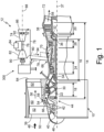
- FIG. 1 is a schematic representation of gas turbine engine 10 that includes boost spool 12 in accordance with an exemplary embodiment of this disclosure.
- Gas turbine engine 10 is a dual spool engine that includes low pressure spool 14 and high pressure spool 16.
- Low pressure spool 14 includes low pressure compressor 18 mechanically and rotationally connected to low pressure turbine 20 by shaft 22, and high pressure spool 16 includes high pressure compressor 24 mechanically and rotationally connected to high pressure turbine 26 by shaft 28.
- Bearings 30 and 32 support shaft 22 of low pressure spool 14, and bearings 34 and 36 support shaft 28 of high pressure spool 16, each at forward and aft shaft ends, respectively.
- Low pressure spool 14 and high pressure spool 16 are coaxial, each extending along and rotating about centerline 37 independently of one another.
- Compressors and turbines 18, 20, 24, and 26 include at least one compressor stage or turbine stage, each stage formed by a row of stationary vanes and a row of rotating blades.
- each of low pressure compressor 18 and high pressure compressor 24 has three stages
- each of low pressure turbine 20 and high pressure turbine 26 has two stages, although the number of stages in each compressor or turbine can be selected based on the desired pressure ratios as is known in the art.
- boost spool 12, low pressure spool 14, and high pressure spool 16 may be referred to as a first spool, a second spool, and/or a third spool in which "first”, “second”, and “third” correspond to one of boost spool 12, low pressure spool 14, and high pressure spool 16.
- first”, “second”, and/or “third” labels may be used in conjunction with corresponding components of the first spool, the second spool, and/or the third spool in order to distinguish components of each spool from components of the other spools.
- variable area turbine 38 includes a row of vanes, each vane rotatable about a vane axis extending in a spanwise direction of the vane.
- the open area through variable area turbine (VAT) 38 changes depending on the stagger angle of vanes with respect to centerline 37.
- the closed position occurs when vanes form a maximum stagger angle with respect to centerline 37 while the open position occurs when vanes form a minimum, and sometimes negative, stagger angle with respect to centerline 37.
- the minimum open area typically coincides with the closed position since vanes tend to rotate toward each other, and in some instances vanes overlap when viewed along centerline 37.
- vanes As vanes move from the closed position towards the open position, the open area through the vane stage increases until a maximum open area is reached, typically near a minimum turning angle, or zero stagger angle position. In some embodiments, the open position coincides with the vane position associated with a maximum open area through the vane row. In other embodiments, vanes can continue to rotate towards the open position in which the vane stagger angle is negative, tending to decrease the open area as the stagger angle becomes more negative.
- a neutral position or nominal position of vanes can be associated with an angular vane position between the open position and the closed position that achieve a desired incident angle with a rotor of low pressure turbine 20.
- Gas turbine engine 10 also includes fan 39 mounted to fan shaft 40.
- One or more bearings 42 support fan shaft 40, which is mechanically and rotationally coupled to low pressure spool 14.
- Fan shaft 40 may be directly connected to shaft 22 of low pressure spool 14. With this arrangement, fan 39 and fan shaft 40 rotate at the same speed and in the same direction as low pressure spool 14. In other embodiments, such as the exemplary embodiment depicted in FIG. 1 , fan shaft 40 may be rotationally coupled to shaft 22 via gearing 44.
- gearing 44 can be an epicyclic gear train that includes a central sun gear mounted to shaft 22, a ring gear mounted to fan shaft 40, and a plurality of planet gears circumferentially spaced about the sun gear and mechanically engaging the ring gear and the sun gear, the planet gears being supported by a planet carrier (not shown).
- gas turbine engines utilizing epicyclic gearing to drive fan 39 and fan shaft 40 restrain the planet carrier to cause fan shaft 40 to rotate slower (and in the opposite direction) than low pressure spool 14. Accordingly, fan 39 and low pressure spool 14 can rotate at speeds that are more efficient for respective blade geometries.
- nose cone 46 guides ambient air flow 48 into inlet 50.
- Rotation of fan 39 which includes circumferentially spaced fan blades 52, compresses ambient air flow 48 before splitter 54 divides flow 48 into bypass flow 56 and core flow 58.
- Bypass flow 56 passes through bypass duct 60 to structural guide vanes 62 and discharges from engine 10 through a bypass flow exhaust nozzle (not shown), which is downstream from structural guide vane outlet 64.
- Inlet guide vanes 66 guide core flow 58 into low pressure compressor 18 that subsequently flows into high pressure compressor 24, each compressor stage further compressing core flow 58.
- Compressed core flow 58 discharges from high pressure compressor 24 into diffuser 68.
- Diffuser 68 fluidly connects high pressure compressor 24 to combustor 70 and includes divergent walls that reduce core flow 58 velocity and thereby increase static pressure of flow 58 before entering combustor 70.
- Combustor 70 can be an annular combustor (or another suitable design). Fuel injected into combustor 70 mixes with compressed core flow 58, and one or more ignitors combust the fuel-to-air mixture to produce a compressed and heated core flow 58 that is discharged into high pressure turbine 26. Core flow 58 interacts with vanes and blades of high pressure turbine 26 causing rotation of shaft 28 about centerline 37 and driving rotation of high pressure compressor 24.
- core flow 58 interacting with vanes and blades of low pressure turbine 20 cause rotation of shaft 22 about centerline 37 to drive rotation of low pressure compressor 18 as well as fan shaft 40 directly or via gearing 44. Downstream of low pressure turbine 20, core flow 58 discharges from engine 10 through exhaust nozzle 72.
- Boost spool 12 includes at least boost compressor 74 and shaft 76 fluidly connected to gas turbine engine 10 by inlet duct assembly 78 and outlet duct assembly 80.
- boost spool 12 also includes one or more of boost turbine 82, combustor 84, and variable inlet guide vanes 86.
- Boost compressor 74 and boost turbine 82 include at least one compressor stage or turbine stage, each stage formed by a row of stationary vanes and a row of rotating blades.
- Variable inlet vanes 86 form an array of circumferentially spaced vanes at an inlet to boost spool 12 and upstream of boost compressor 74.
- Each vane of variable inlet guide vanes 86 is rotatable about a vane axis that extends in a spanwise direction of the vane.
- An angular position of variable inlet guide vanes 86 ranges between a closed position, a neutral or nominal position, and an open position in the same manner as vanes of variable area turbine 38.
- variable inlet vanes 86 can pivot to decrease or increase the open inlet area in order to vary the amount of core flow 58 diverted into boost compressor 74 through inlet duct assembly 78.
- Shaft 76 mechanically and rotationally connects boost compressor 74 to boost turbine 82, each component arranged coaxially with boost axis 88.
- Bearings 90 and 92 support boost spool 12 with respect to a stationary casing, which may be affixed or incorporated to a casing of gas turbine engine 10.
- Transmission 300 mechanically and rotationally couples boost spool 12 to one or more spools of gas turbine engine 10 (e.g., low pressure spool 14 and/or high pressure spool 16) as discussed further below.
- boost axis 88 can be parallel and offset from centerline 37 of gas turbine engine 10 as schematically shown by FIG. 1 .
- FIG. 1 shows boost spool 12 with a reverse flow orientation (i.e., aft-to-forward flow) such that a flow direction through boost spool 12 from compressor 74 to turbine 82 is opposite a flow direction (i.e., forward-to-aft flow) through gas turbine engine 10 from inlet 50 to outlet 64 and from inlet 50 to nozzle 72.
- boost axis 88 can be oblique or perpendicular to centerline 37.
- boost spool 12 For all mounting positions of boost spool 12, the location and orientation of boost spool 12 permits boost spool 12 to receive a compressed air flow from gas turbine engine 10 and to discharge an expanded air flow to gas turbine engine 10.
- Boost spool 12 can receive a compressed airflow from any compressor stage of gas turbine engine 10 to achieve varying degrees of boost compression.
- boost spool 12 receives a compressed air flow from a location that is downstream from the last compressor stage of the gas turbine engine.
- boost spool 12 receives airflow from diffuser 68 and discharges an expanded airflow to diffuser 68.
- boost spool receives airflow from diffuser 68 and discharges an expanded airfoil to both diffuser 68 and combustor 70, which is downstream of high pressure compressor 24 and upstream from high pressure turbine 26.
- boost spool 12 receives a portion of core flow 58 extracted from diffuser 68 (i.e., boost flow 94) and routed to an inlet of boost compressor 74 through inlet duct assembly 78.
- boost flow 94 Within boost compressor 74, the pressure and temperature of boost flow increases with each compressor stage.
- Compressed boost flow 94 enters combustor 84 where injected fuel mixes with compressed boost flow 94. Once the fuel-air mixture is ignited, boost flow 94 discharges into boost turbine 82.
- Turbine 82 expands boost flow 94 across each turbine stage, driving turbine 82, shaft 76, and compressor 74. Expanded boost flow 94 discharges from boost spool 12 through outlet duct assembly 80, which may route discharged air to diffuser 68, combustor 70, or both diffuser 68 and combustor 70.
- FIG. 2 schematically depicts inlet duct assembly 78 that extracts a portion of core flow 58 from diffuser 68 and outlet duct assembly 80 that discharges the boost flow to diffuser 68 and combustor 70.
- diffuser 68 includes inner peripheral wall 96 and outer peripheral wall 98 spaced radially outward from wall 96.
- Multiple struts 100 extend from inner peripheral wall 96 to outer peripheral wall 98 of diffuser.
- FIG. 2 depicts five struts 100. However more or less struts 100 can be used in other examples, each incorporating features of inlet duct assembly 78 and outlet duct assembly 80 discussed below.
- Combustor 70 includes outer casing 102 and spaced radially from inner casing 104 to define an annular combustion chamber. Inner casing 104 and outer casing 102 are thermally protected by segmented liners 106.
- inlet duct assembly 78 includes multiple branch ducts 108 collected into inlet manifold 110. Each branch duct 108 communicates with diffuser 68 via respective branch inlets 112.
- branch inlets 112 can be formed by inner and/or outer peripheral walls of diffuser 68 such that branch ducts 108 extract core flow 58 through inner and outer walls of diffuser 68.
- branch inlets 112 are formed by respective struts 100.
- Branch inlet ducts 108 extend from branch inlets 112 to inlet manifold 110.
- Inlet manifold 110 can be a pipe, duct, or plenum accommodating the collected flow through each branch inlet duct 108 and routing the accumulated inlet flow to inlet of boost spool 12.
- outlet duct assembly 80 can include one or more ducts extending from an outlet of boost turbine 82 to diffuser 68, combustor 70, or both diffuser 68 and combustor 70.
- outlet duct assembly 80 can include main duct 114 extending from an outlet of boost turbine 82 to one or more branch outlet ducts 116, one or more branch outlet ducts 116, or one or more branch outlet ducts 116 and one or more branch outlet ducts 118.
- Each branch outlet duct 116 extends from main duct 114 to one of boost outlets 120 formed in an inner peripheral wall or an outer peripheral wall of diffuser 68, or a wall of strut 104, placing main duct 114 and boost turbine 82 in communication with diffuser 68.
- Each branch outlet duct 118 extends from main duct 114 to one of boost outlets 122 formed in a peripheral wall of combustor 70, placing main duct 114 and boost turbine 82 in communication with combustor 70.
- outlet duct assembly 80 includes main duct 114, multiple branch ducts 116, and branch duct 118.
- Main duct 114 extends from boost turbine 82 to each branch outlet duct 116 and branch duct 118.
- Branch outlet ducts 116 extend from main duct 114 to boost outlets 120 formed in walls of respective struts 100.
- Branch outlet duct 118 extends from main duct 114 to boost outlet 122 formed in a peripheral wall bounding a combustion zone of combustor 70.
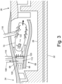
- FIG. 3 is a schematic of diffuser 68 and combustor 70 of gas turbine engine 10.
- branch inlet duct 108 extracts air from core flow 58 through inlet 112, and branch duct 116 discharges boost exhaust flow through outlet 120.
- Branch inlets 112 and branch outlets 120 are formed by strut 100.
- One or both of branch inlet 112 and branch outlet 120 can extend from inner peripheral wall 96 to outer peripheral wall 98.
- Outlet 122 of branch outlet duct 118 discharges through outer casing of combustor 70. The location of outlet 122 is spaced axially downstream from injectors 124, or between injectors 124 and high pressure turbine 26.
- FIG. 4 depicts another schematic view of struts 100 and the flow distribution within diffuser 68.
- Each strut 100 includes first side wall 126 and second side wall 128 extending from leading edge 130 of strut 100 to rear wall 132.
- Inlets 112 are disposed in one of sidewalls 126 and 128 while outlets 120 are disposed in the other sidewall opposite the inlet sidewall.
- boost spool 12 a portion of compressed core flow 58 enters each inlet 112 and flows through branch inlet ducts 108 and manifold 12to the inlet of boost spool 12 and boost compressor 74.
- a portion of boost spool flow exiting boost turbine 82 flows through each branch outlet duct 116 before discharging through each outlet 120 into diffuser 68.
- An outlet flow division can be achieved with appropriate selection of length, cross-sectional area, and routing of main duct 114, diffuser branch ducts 116, combustor branch duct 118 and associated outlets 120 and 122 of outlet duct assembly 80.
- a minimum mass flow rate of boost exhaust discharged to diffuser through outlets 120 relates to an amount of flow required to maintain flow into boost spool 12 through inlet duct assembly 78.
- Adequate flow through inlet duct assembly 78 can be achieved by maintaining at least a minimum static pressure at branch inlets 112 throughout all operating conditions during which boost spool 12 can be operated, including transient periods associated with starting or stopping boost spool 12.
- the maximum mass flow rate of boost exhaust discharged to diffuser 68 through outlets 120 relates to a maximum temperature of fuel injectors within combustor 70.
- boost exhaust mass flow rate increases, a temperature of compressed air entering combustor 70 increases. Accordingly, the maximum permitted temperatures of components of combustor 70 during continuous operation limits the maximum mas flow rate of boost exhaust returned to diffuser 68 through outlets 120.
- five percent to forty percent of boost exhaust flow can be discharged into diffuser 68 while the remainder ninety-five percent to sixty percent of boost exhaust flow can be discharged to combustor 70.
- boost exhaust between diffuser 68 and combustor 70 allows boost outlets 120 to extend from the inner peripheral wall to the outer peripheral wall of diffuser 68 as shown in FIG. 3 .
- boost outlets 120 As the radial extent of boost outlets 120 approaches the full radial extent of diffuser 68 at struts 100, flow uniformity and flow stability increase within diffuser 68 while component temperatures within combustor 70 remain acceptable for continuous operation.
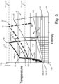
- FIG. 5 is a T-s diagram illustrating the thermodynamic performance of gas turbine engine 10 boosted by spool 12 relative to gas turbine engine 10 operating without boost spool 12. Entropy is displayed along abscissa axis 134, and temperature is displayed along ordinate axis 136, each increasing from origin 138. Dashed curve A depicts the preferred thermodynamic cycle of gas turbine engine 10 operating without boost engaged at takeoff power. Dashed curve B depicts the thermodynamic cycle of gas turbine engine 10 were boost to be engaged while operating at takeoff power on a hot day. Solid curve C depicts gas turbine engine 10 operating without boost spool 12 engaged while operating at cruise power.
- Solid curves C and D are defined by points 2C, 3C, 4C, and 5C and points 2D, 3D, 4D, and 5D in a similar manner to curves A and B.
- An engine operating along curve A has less OPR (value Y) than an engine operating on any of the other curves (i.e., curves C and D having an OPR equal to value X and curve B having an OPR value equal to Z).
- an engine operating on curves C and D have an OPR value X that is greater than an engine operating on curve B with an OPR value Z.
- the temperature entering the compressor section of gas turbine engine 10 at cruise power is lower than the temperature entering the compressor section of gas turbine engine 10 at takeoff power because the ambient temperature at cruising altitude is lower than the ambient temperature during a hot day takeoff.
- the ambient temperature can be approximately -26.1 degrees Celsius (or about -15 degrees Fahrenheit) while on a hot day takeoff, the ambient temperature can be approximately 46.1 degrees Celsius (or about 115 degrees Fahrenheit).
- the temperature within the engine at points 3A, 3B, 3C, and 3D are limited to a line of constant temperature labeled "T3 Limit" while the temperature at points 4A, 4B, 4C, and 4D are limited to a line of constant temperature labeled "T4 Limit".
- Unboosted operation of gas turbine engine 10 represented by dashed curve A trades engine fuel efficiency and engine materials life between temperature limits during a hot day takeoff and cruising. As a result, the OPR of unboosted operation of engine 10 is reduced by hot day takeoff conditions (i.e., the temperature at point 4A is lower than the temperature at 4B).
- the area bounded by dashed curve A and a line connecting points 5A and 2A represent the amount of work completed by engine 10 while operating at takeoff power and without boost spool 12 operation.
- the area bounded by dashed curve B and a line connecting points 5B and 2B represent the amount of work completed by engine 10 while operating at takeoff power and with boost spool 12 operation.
- the two areas are the same and the amounts of work completed by the engine at takeoff are the same.
- the amount of heat energy rejected by gas turbine engine 10 while operating in accordance with dashed curve A is shown by horizontally-hatched area 140.
- the thermodynamic efficiency of gas turbine engine 10 operating in accordance with dashed curve A is the work energy divided by the summation of work and rejected heat energy defined by curve A.
- gas turbine engine 10 with the same OPR as boost engine operation depicted by curve D does not have the improved engine fuel efficiency and same life of operation.
- the temperature at 4B is higher than the temperature 4A.
- gas turbine engine 10 can be operated without boost spool 12 during hot day takeoff conditions (i.e., dashed curve A) and can be operated with boost spool 12 at cruise power (i.e., solid curve D) to achieve greater thermal efficiency at cruise power while satisfying thermal limits for hot day takeoff conditions.
- FIG. 6 is a schematic of controller 150 that regulates the operation of gas turbine engine 10 and, more particularly, coupling and decoupling of boost spool 12 via one of transmission 300. Additionally, controller 150 regulates fuel flow rates to primary combustor 70 and secondary combustor 84 based on one or more engine parameters, aircraft parameters, and/or exterior conditions. Controller 150 can include a standalone control unit or a control module incorporated into another control unit. Furthermore, controller 150 can be an amalgamation of distinct control units and/or distinct control modules that together perform the functions described in this disclosure. In some embodiments, controller 150 can be a full authority digital engine control (FADEC), an electric engine controller (EEC), or an engine control unit (ECU).
- FADEC full authority digital engine control
- EEC electric engine controller
- ECU engine control unit
- Controller 150 includes processor 152, memory 154, and input/output interface 156.
- Processor 152 executes one or more control algorithms 158 stored within memory 154 to output engine control signals 160 based on one or more input signals 162.
- Examples of processor 152 can include any one or more of a microprocessor, a controller, a digital signal processor (DSP), an application specific integrated circuit (ASIC), a field-programmable gate array (FPGA), or other equivalent discrete or integrated logic circuitry.
- DSP digital signal processor
- ASIC application specific integrated circuit
- FPGA field-programmable gate array
- Memory 154 can be configured to store information within controller 154.
- Memory 154 in some examples, is described as computer-readable storage media.
- a computer-readable storage medium can include a non-transitory medium.
- the term "non-transitory" can indicate that the storage medium is not embodied in a carrier wave or a propagated signal.
- a non-transitory storage medium can store data that can, over time, change (e.g., in RAM or cache).
- Memory 154 can include volatile and non-volatile computer-readable memories. Examples of volatile memories can include random access memories (RAM), dynamic random-access memories (DRAM), static random-access memories (SRAM), and other forms of volatile memories. Examples of non-volatile memories can include, e.g., magnetic hard discs, optical discs, flash memories, or forms of electrically programmable memories (EPROM) or electrically erasable and programmable (EEPROM) memories.
- RAM random access memories
- DRAM dynamic random-access memories
- SRAM static
- I/O interface 156 can be a series of input and output channels that electrically communicate with an engine control bus.
- the engine control bus interconnects controller 150 with various components of the gas turbine engine 10 described above such that engine control signals 160 can be transmitted to individual engine components and input signals 162 can be received.
- Engine control signals 160, input signals 162, or both engine control signals 160 and input signals 162 can be an analog signal or a digital signal.
- an analog signal can be a voltage that varies between a low voltage to a high voltage whereas digital signals can be a series of discrete voltage states distributed over a voltage range.
- engine control signals 160 cause various components of gas turbine engine 10 to change state or position.
- engine control signals 160 can be used to vary the position of one or more fuel valves to vary the fuel rate entering a combustor.
- Other examples of engine control signals 160 include signals associated with engagement or disengagement of clutches and an angular position of variable vane stages.
- Input signals 162 are representative of one of engine parameters, aircraft parameters, and environmental parameters.
- Exemplary engine parameters include rotational speed of a low pressure spool, high pressure spool, boost spool, and/or fan shaft, the state or position of fuel valves, bleed valves, the state or position of clutch assemblies, the temperature or pressure within the compressor, combustor, or turbine, and engine power.
- Aircraft parameters include various parameters associated with an aircraft such as power lever angle, altitude, pitch angle, yaw angle, roll angle, rate of climb, and airspeed, among other possible parameters.
- Exterior parameters include ambient temperature and pressure at the inlet of gas turbine engine 10.
- FIG. 7A and FIG. 7B are schematic views depicting an exemplary embodiment of gas turbine engine 10 that includes transmission 300 for driving boost spool 12 and accessory gearing 302.
- Transmission 300 includes drive gear 304, input gear 306, tower shaft 308, output gear 310, differential input gear 312, shaft 314, sun gear 316, planet gears 318, planet carrier 320, ring gear 322, shaft 324, locking element 326, and clutch 328.
- transmission 300 forms a biased, locking differential gearbox in which low pressure shaft 22 and boost shaft 76 are inputs and accessory gearing 302 is the output.
- Low pressure spool 14 is rotationally coupled to sun gear 316 to provide a first input to the biased, locking differential gearbox.
- Drive gear 304 mounts to shaft 22 of low pressure spool 14.
- Tower shaft 308 extends radially outward from shaft 22 of low pressure spool 14 towards boost spool 12.
- At an interior or radially inner end tower shaft 308 includes input gear 306 enmeshed with drive gear 304.
- tower shaft 308 includes output gear 310 enmeshed with differential input gear 312.
- Differential input gear 312 is mounted on shaft 314, which extends from differential input gear 312 to sun gear 316.
- Sun gear 316 is mounted to, or otherwise rotationally coupled to shaft 314. Accordingly, shaft 22 of low pressure spool 14 is rotationally coupled to sun gear 316 via tower shaft 308 and shaft 314 and associated gearing.
- Boost spool 12 is rotationally coupled to planet carrier 320 to provide a second input of the biased, locking differential gearbox.
- Planet carrier 320 is mounted to shaft 76 of boost spool 12 such that shaft 76 and planet carrier 320 rotate at the same speed and in the same direction.
- Planet carrier 320 includes multiple bearing journals equally-spaced circumferentially about a rotational axis of planet carrier 320.
- Planet gears 318 are supported from respective bearing journals.
- Clutch 328 is disposed between shaft 76 of boost spool 12 and planet carrier 320 of transmission 300.
- boost spool 12 and planet carrier 320 rotate at the same speed and in the same direction about boost axis 88.
- boost spool 12 and planet carrier 320 are rotationally uncoupled such that boost spool 12 and planet carrier 320 rotate independently.
- Accessory gearing 302 is rotationally coupled to ring gear 322 to provide an output of the biased, locking differential gearbox.
- Accessory gearing 302 includes one or more gears enclosed within housing 330 of accessory gearbox 332. Housing 330 subtends a sector about casing 334 of engine 10.
- One or more gears of accessory gearing 302 are driven by ring gear 322 directly or a shaft and output gear joined to ring gear 322. At least some of the gears of accessory gearing 302 are rotationally coupled to respective output shafts 336.
- Each output shaft 336 drives an engine accessory (e.g., a fuel pump, generators, constant speed drives, lubricating oil pumps, hydraulic pumps, and engine starters).
- engine accessory e.g., a fuel pump, generators, constant speed drives, lubricating oil pumps, hydraulic pumps, and engine starters.
- Locking element 326 translates between an engaged state and a disengaged state.
- locking element 326 rotationally couples planet carrier 320 to ring gear 322 or to sun gear 316 such that planet carrier 320, sun gear 316, and ring gear 322 rotate at a common speed.
- locking element 326 rotationally uncouples planet carrier 320 from ring gear 322 or sun gear 316 such that planet carrier 320, ring gear 322, and sun gear 316 may rotate relative to each other.
- engaging locking element 326 increases the percentage of power transferred to low pressure spool 14 from boost spool 12 relative to the disengaged position of locking element 326.
- boost spool 12 splits between low pressure spool 14 and accessory gearing 302.
- boost spool 12 in concert with gas turbine engine 10 and transmission 300 depends on the operational range of gas turbine engine 10 input by power lever angle (PLA).
- the power lever angle (PLA) varies between zero percent (i.e., PLA 0) and one hundred percent (i.e., PLA 100).
- a power lever angle (PLA) equal to zero corresponds with an engine shutdown condition whereby fuel flow to combustor 70 stops and any remainder fuel is burned off or returned to fuel tanks of the aircraft.
- intermediate power lever angles include engine start, ground idle and/or flight idle, a reduced cruising power level associated with loiter, cruise, and climb.
- a power lever angle (PLA) equal to one hundred percent corresponds to takeoff power.
- power lever angle (PLA) values can be engine and/or aircraft dependent
- controller 150 Based on power lever angle (PLA) and one or more additional engine parameters, aircraft parameters, and/or external parameters, controller 150 transmits control signals to components of transmission 300 as well as fuel system components regulating fuel flows to combustor 70 (i.e., a primary combustor) and combustor 84 (i.e., a secondary combustor) to operate gas turbine engine 10 as described in the following scenarios.
- PPA power lever angle
- gas turbine engine 10 includes a minimum continuous power level and a maximum continuous power level.
- the minimum continuous power level and the maximum continuous power level correspond to the minimum and maximum power levels at which gas turbine engine 10 can operate continuously and in which pressure and temperature at various locations within the engine stabilize.
- the minimum continuous power level can correspond to the ground idle condition while the maximum continuous power level can correspond to the takeoff conditions.
- Boost spool 12 operates within an intermediate power range of gas turbine engine 10.
- the intermediate power range is a subset of sequential power levels of gas turbine engine 10 bound by a minimum power level and a maximum power level.
- the minimum power level of intermediate power range may coincide with power lever angles (PLA) corresponding to engine start, ground idle, flight idle, loiter, cruise, or a power level between engine start and cruise.
- the maximum power level of intermediate power range may coincide with power lever angles (PLA) corresponding to cruise, climb, takeoff, or a power level condition between cruise and takeoff power.
- the intermediate power range can be further divided into two or more power subranges. For instance, sequentially continuous low power subrange and high power subrange can define the intermediate power range.
- the low power subrange extends from the minimum power level of intermediate power range to an intermediate power level greater than the minimum power level and less than the maximum power level of intermediate power range.
- the high power subrange extends from the intermediate power level to the maximum power level of the intermediate power range.
- Table 1 describes the operational range of gas turbine engine 10 equipped with transmission 300.
- the intermediate power range extends that include the cruise condition and includes at least two power subranges.
- High power subrange extends from the loiter condition to the cruise condition.
- controller 150 varies a fuel flow rate delivered to secondary combustor 84 based on rotational speed of accessory gearbox 332 (NAGB).
- NAGB accessory gearbox 332
- clutch 328 is engaged to rotationally couple boost shaft 76 to planet carrier 320.
- Locking member 326 is disengaged allowing planet carrier 320 to rotate relative to sun gear 316 and ring gear 322.
- controller 150 increases the open area through the variable area turbine (VAT) 38 by commanding variable area turbine 38 to an open position or towards the open position.
- VAT variable area turbine
- Low power operation spans from ground idle power (PLA ⁇ 10) to loiter power (PLA ⁇ 40).
- controller 150 regulates a fuel flow rate delivered to primary combustor 70 based on the power lever angle (PLA) and, contemporaneously, regulating a fuel flow rate delivered to secondary combustor 84 based on the speed of accessory gearbox 332. While clutch 328 remains engaged and locking member 326 remains disengaged, variable turbine vanes are moved to or towards a nominal position, decreasing an open area through variable turbine vanes.
- locking member 326 When the power level corresponds to loiter power or a lesser power level, locking member 326 disengages, allowing planet carrier 320, ring gear 322, and sun gear 316 to rotate at different speeds. As the power lever angle (PLA) exceeds loiter power, controller 150 moves locking element 326 to the engaged position, rotationally coupling planet carrier 320 to ring gear 322 or to sun gear 316, tying the gears to a common speed.
- PPA power lever angle
- controller 150 varies a fuel flow rate delivered to primary combustor 70 based the minimum engine pressure ratio (EPRmin) and simultaneously varies a fuel flow rate delivered to secondary combustor 84 based on a position of the power lever (PLA) or a requested power level.
- EPRmin engine pressure ratio
- VAT variable area turbine
- controller 150 disengages clutch 328 uncoupling boost spool 12 from low pressure spool 14 and stops fuel flowing to secondary combustor 84.
- the fuel flow rate delivered to primary combustor 70 is regulated by controller 150 based on the power lever angle (PLA) or requested power level.
- PPA power lever angle
- VAT variable area turbine
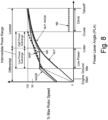
- FIG. 8 depicts an exemplary speed profile of gas turbine engine 10 equipped with transmission 300.
- rotational speeds of high pressure spool 16 (NHP), low pressure spool 14 (NLP), boost spool 12 (NB), and the input of accessory gearbox 332 (NAGB) are expressed as a percentage of respective maximum operational speeds of each spool or component.
- Dashed lines indicate starting, shutdown, or unpowered operation such as when a spool or component freewheels.
- Solid lines indicate operation of gas turbine engine 10 while delivering fuel to primary combustor 70, secondary combustor 84, or both primary and secondary combustors.
- the fuel flow rate delivered to combustor 84 within the low power subrange varies such that the differential output between the low pressure spool input and the boost spool input produces a constant speed, or minimal speed variation, at ring gear 322. Accordingly, engine accessories driven by accessory gearing via ring gear 322 are not required to accommodate larger operating speed ranges.
- the gear ratios between boost spool 12 and low pressure spool 14 is selected such that boost spool 12 attains its maximum operating speed when low pressure spool 14 attains approximately eighty percent to ninety percent of its maximum operating speed. Furthermore, the maximum operating speed of boost spool 12 coincides with the cruise condition and thereby provides increases the maximum overall pressure ratio (OPR) of gas turbine engine 10 during the longest phases of flight.
- boost spool 12 can be uncoupled from low pressure spool and accessory gearbox 332 by disengaged clutch 328.
- preventing rotation of planet carrier 320 by engaging locking element 326 converts ring gear 322, planet carrier 320, and sun gear 316 into a fixed speed ratio between low pressure spool 14 and accessory gearing 302. Accordingly, engine accessories are driven at a fixed speed ratio relative to low pressure spool 14 from cruise power to takeoff power.
Landscapes
- Engineering & Computer Science (AREA)
- Chemical & Material Sciences (AREA)
- Combustion & Propulsion (AREA)
- Mechanical Engineering (AREA)
- General Engineering & Computer Science (AREA)
- Control Of Turbines (AREA)
- Retarders (AREA)
Claims (10)
- Gasturbinentriebwerk (10), umfassend:eine erste Welle (16), die einen ersten Verdichter (24) und eine erste Turbine (26) umfasst und an einer ersten Rotationsachse (28) montiert ist;eine zweite Welle (12), die einen zweiten Verdichter (74) und eine zweite Turbine (82) umfasst und an einer zweiten Rotationsachse (76) montiert ist;eine dritte Welle (14), die einen dritten Verdichter (18) und eine dritte Turbine (20) umfasst und an einer dritten Rotationsachse (22) montiert ist;eine Vielzahl von Motorzubehörteilen;ein Hilfsgetriebe (332), umfassend:ein Gehäuse (330);ein Sonnenrad (316), das drehfest mit der dritten Rotationsachse (22) gekoppelt ist;ein Hohlrad (322), das drehfest an die Vielzahl von Motorzubehörteilen gekoppelt ist; undeine Vielzahl von Planetenrädern (318), die mit dem Sonnenrad (316) und dem Hohlrad (322) verzahnt sind und von einem Träger (320) getragen werden, wobei der Träger (320) drehfest an die zweite Rotationsachse (76) gekoppelt ist;eine primäre Brennkammer (70), die mit dem ersten Verdichter (24) und der ersten Turbine (26) in Verbindung steht; undeine sekundäre Brennkammer (84), die mit dem zweiten Verdichter (74) und der zweiten Turbine (82) in Verbindung steht, wobei ein primärer Strömungsweg (58) in axialer Strömungsreihe den dritten Verdichter (18), den ersten Verdichter (24), die primäre Brennkammer (70), die erste Turbine (26) und die dritte Turbine (20) beinhaltet, ein sekundärer Strömungsweg (94) in axialer Strömungsreihe den zweiten Verdichter (74), die sekundäre Brennkammer (84) und die zweite Turbine (82) beinhaltet und der sekundäre Strömungsweg (94) den primären Strömungsweg (58) zwischen dem ersten Verdichter (24) und der primären Brennkammer (70) kreuzt.
- Gasturbinentriebwerk (10) nach Anspruch 1, wobei das Hilfsgetriebe (332) ein Sperrelement (326) umfasst, das aus einer ausgerückten Position in eine eingerückte Position überführbar ist, und der Träger (320) in der eingerückten Stellung drehfest an das Sonnenrad (316) oder das Hohlrad (322) gekoppelt ist, um dadurch eine Drehung des Trägers (320) in Bezug auf das Sonnenrad (316) oder das Hohlrad (322) zu verhindern.
- Gasturbinentriebwerk (10) nach Anspruch 1 oder 2, wobei mindestens eine Stufe der dritten Turbine (20) eine Turbine mit variabler Fläche (38) beinhaltet und Leitschaufeln der Turbine mit variabler Fläche (38) zum Variieren einer offenen Fläche der Turbine mit variabler Fläche (38) um jeweilige Schwenkachsen drehbar sind.
- Gasturbinentriebwerk (10) nach einem der vorhergehenden Ansprüche, ferner umfassend eine Turmrotationsachse (308), die das Sonnenrad (316) drehfest mit der dritten Rotationsachse (22) verbindet.
- Gasturbinentriebwerk (10) nach einem der vorhergehenden Ansprüche, wobei eine Drehachse der zweiten Rotationsachse (76) versetzt und parallel zu einer Drehachse der ersten Rotationsachse (28) und einer Drehachse der dritten Rotationsachse (22) ist und die erste Rotationsachse (28) konzentrisch zu der dritten Rotationsachse (22) ist.
- Gasturbinentriebwerk (10) nach einem der vorhergehenden Ansprüche, wobei eine zweite maximale Geschwindigkeit eine maximale Betriebsgeschwindigkeit der zweiten Welle (12) ist, die dritte maximale Geschwindigkeit eine maximale Betriebsgeschwindigkeit der dritten Welle (14) ist und ein Übersetzungsverhältnis der zweiten Welle (12) und der dritten Welle (14) konstant ist und derart gewählt ist, dass die zweite Welle (12) mit der zweiten maximalen Geschwindigkeit dreht, wenn eine dritte Drehzahl der dritten Welle (14) gleich oder geringer als 90 % der dritten maximalen Geschwindigkeit und größer als oder gleich 80 % der maximalen Geschwindigkeit ist.
- Gasturbinentriebwerk (10) nach einem der vorhergehenden Ansprüche, ferner umfassend eine zwischen dem Träger (320) und der zweiten Rotationsachse (76) angeordnete Kupplung (328), wobei die Kupplung (328) einen ausgerückten Zustand, in dem die zweite Rotationsachse (76) von dem Träger (320) abgekoppelt ist, und einen eingerückten Zustand, in dem die zweite Rotationsachse (76) mit dem Träger (320) gekoppelt ist, beinhaltet.
- Gasturbinentriebwerk (10) nach einem der vorhergehenden Ansprüche, wobei das Gehäuse (330) des Hilfsgetriebes (332) einen Sektor um einen Mantel des Gasturbinentriebwerks (10) herum begrenzt.
- Gasturbinentriebwerk (10) nach einem der vorhergehenden Ansprüche, wobei die dritte Rotationsachse (22) konzentrisch zu der ersten Rotationsachse (28) ist und die zweite Rotationsachse (76) gegenüber der ersten Rotationsachse (28) und der dritten Rotationsachse (22) versetzt ist.
- Gasturbinentriebwerk (10) nach einem der vorhergehenden Ansprüche, wobei der erste Verdichter (24) ein Hochdruckverdichter (24) ist, der dritte Verdichter (18) ein Niederdruckverdichter (18) ist, die erste Turbine (26) eine Hochdruckturbine (26) ist und die dritte Turbine (20) eine Niederdruckturbine (20) ist.
Priority Applications (1)
| Application Number | Priority Date | Filing Date | Title |
|---|---|---|---|
| EP25167839.7A EP4553311A3 (de) | 2022-05-05 | 2023-05-04 | Getriebe und verfahren zur steuerung einer verstärkungsspule |
Applications Claiming Priority (1)
| Application Number | Priority Date | Filing Date | Title |
|---|---|---|---|
| US17/662,195 US11898490B2 (en) | 2022-05-05 | 2022-05-05 | Transmission and method for control of boost spool |
Related Child Applications (1)
| Application Number | Title | Priority Date | Filing Date |
|---|---|---|---|
| EP25167839.7A Division EP4553311A3 (de) | 2022-05-05 | 2023-05-04 | Getriebe und verfahren zur steuerung einer verstärkungsspule |
Publications (3)
| Publication Number | Publication Date |
|---|---|
| EP4273390A2 EP4273390A2 (de) | 2023-11-08 |
| EP4273390A3 EP4273390A3 (de) | 2023-11-15 |
| EP4273390B1 true EP4273390B1 (de) | 2025-04-02 |
Family
ID=86329777
Family Applications (2)
| Application Number | Title | Priority Date | Filing Date |
|---|---|---|---|
| EP23171720.8A Active EP4273390B1 (de) | 2022-05-05 | 2023-05-04 | Getriebe und verfahren zur steuerung einer boost-welle |
| EP25167839.7A Pending EP4553311A3 (de) | 2022-05-05 | 2023-05-04 | Getriebe und verfahren zur steuerung einer verstärkungsspule |
Family Applications After (1)
| Application Number | Title | Priority Date | Filing Date |
|---|---|---|---|
| EP25167839.7A Pending EP4553311A3 (de) | 2022-05-05 | 2023-05-04 | Getriebe und verfahren zur steuerung einer verstärkungsspule |
Country Status (2)
| Country | Link |
|---|---|
| US (2) | US11898490B2 (de) |
| EP (2) | EP4273390B1 (de) |
Families Citing this family (1)
| Publication number | Priority date | Publication date | Assignee | Title |
|---|---|---|---|---|
| US12552545B1 (en) * | 2025-03-03 | 2026-02-17 | Rtx Corporation | Drivetrain for aircraft powerplant with boosted turbine engine |
Family Cites Families (40)
| Publication number | Priority date | Publication date | Assignee | Title |
|---|---|---|---|---|
| US3677012A (en) | 1962-05-31 | 1972-07-18 | Gen Electric | Composite cycle turbomachinery |
| GB1069033A (en) | 1965-01-30 | 1967-05-17 | Rolls Royce | Improvements in or relating to gas turbine jet propulsion engines |
| US4147024A (en) | 1977-09-15 | 1979-04-03 | Avco Corporation | Dual cycle gas turbine engine system |
| GB2089894B (en) | 1980-12-22 | 1985-08-14 | Gen Electric | Gas turbine engine air dispensing arrangement |
| GB9313905D0 (en) | 1993-07-06 | 1993-08-25 | Rolls Royce Plc | Shaft power transfer in gas turbine engines |
| US7464533B2 (en) | 2003-01-28 | 2008-12-16 | General Electric Company | Apparatus for operating gas turbine engines |
| GB0805177D0 (en) | 2008-03-20 | 2008-04-30 | Rolls Royce Plc | A gas turbine engine arrangement |
| US20100170262A1 (en) | 2009-01-06 | 2010-07-08 | Kaslusky Scott F | Aircraft power and thermal management system with electric co-generation |
| US20100326085A1 (en) | 2009-06-25 | 2010-12-30 | Veilleux Leo J | Lightweight start system for a gas turbine engine |
| US8684304B2 (en) | 2010-11-16 | 2014-04-01 | Rolls-Royce Corporation | Aircraft, propulsion system, and system for taxiing an aircraft |
| US8690099B2 (en) | 2010-11-16 | 2014-04-08 | Rolls-Royce Corporation | Aircraft and propulsion system |
| US8955335B2 (en) | 2010-12-30 | 2015-02-17 | Rolls-Royce Corporation | System, propulsion system and vehicle |
| US20130247539A1 (en) | 2012-03-26 | 2013-09-26 | Richard John Hoppe | Multi-shaft power extraction from gas turbine engine |
| US9752500B2 (en) | 2013-03-14 | 2017-09-05 | Pratt & Whitney Canada Corp. | Gas turbine engine with transmission and method of adjusting rotational speed |
| US10240479B2 (en) * | 2013-08-07 | 2019-03-26 | United Technologies Corporation | Variable area turbine arrangement for a gas turbine engine |
| GB201414661D0 (en) | 2014-08-19 | 2014-10-01 | Rolls Royce Plc | Gas turbine engine and method of operation |
| US10151211B2 (en) | 2015-01-10 | 2018-12-11 | Florida Turbine Technologies, Inc. | Apparatus and process for converting an aero gas turbine engine into an industrial gas turbine engine for electric power production |
| GB201518788D0 (en) | 2015-10-23 | 2015-12-09 | Rolls Royce Plc | Aircraft pneumatic system |
| US20170218844A1 (en) | 2016-02-01 | 2017-08-03 | United Technologies Corporation | Cooling air for variable area turbine |
| US20170241336A1 (en) | 2016-02-24 | 2017-08-24 | Russell B. Jones | Process for retrofitting an industrial gas turbine engine for increased power and efficiency |
| US10273883B2 (en) * | 2016-02-26 | 2019-04-30 | The Boeing Company | Engine accessory drives systems and methods |
| US20170298826A1 (en) | 2016-04-18 | 2017-10-19 | John E. Ryznic | Industrial gas turbine engine with turbine airfoil cooling |
| US10669940B2 (en) | 2016-09-19 | 2020-06-02 | Raytheon Technologies Corporation | Gas turbine engine with intercooled cooling air and turbine drive |
| US20180156121A1 (en) | 2016-12-05 | 2018-06-07 | United Technologies Corporation | Gas Turbine Engine With Intercooled Cooling Air and Controlled Boost Compressor |
| US10995673B2 (en) | 2017-01-19 | 2021-05-04 | Raytheon Technologies Corporation | Gas turbine engine with intercooled cooling air and dual towershaft accessory gearbox |
| US10961919B2 (en) | 2017-08-29 | 2021-03-30 | Pratt & Whitney Canada Corp | Corrected parameters control logic for variable geometry mechanisms |
| US11333076B2 (en) | 2017-12-21 | 2022-05-17 | Raytheon Technologies Corporation | Power takeoff transmission |
| US10563591B2 (en) | 2018-01-17 | 2020-02-18 | United Technologies Corporation | Systems and methods of low spool power extraction |
| US11015523B2 (en) | 2018-06-05 | 2021-05-25 | Raytheon Technologies Corporation | Turbofan with bleed supercharged auxiliary engine |
| US20200056497A1 (en) | 2018-08-17 | 2020-02-20 | United Technologies Corporation | Hybrid gas turbofan powered sub-idle descent mode |
| US11415044B2 (en) | 2018-06-19 | 2022-08-16 | Raytheon Technologies Corporation | Multi-engine architecture with linkages to multiple spools |
| US11143142B2 (en) * | 2018-08-01 | 2021-10-12 | United Technologies Corporation | Adaptive engine with boost spool |
| US10767568B2 (en) | 2018-09-11 | 2020-09-08 | Raytheon Technologies Corporation | Dual spool power extraction with superposition gearbox |
| US11319883B2 (en) | 2019-02-20 | 2022-05-03 | Honeywell International Inc. | Auxiliary power unit power compressor health state diagnostic system and method |
| US11485503B2 (en) * | 2019-03-29 | 2022-11-01 | Pratt & Whitney Canada Corp. | Hybrid aircraft propulsion power plants |
| US11041462B2 (en) * | 2019-06-05 | 2021-06-22 | Raytheon Technologies Corporation | Hybrid turbofan with differential electrical and mechanical power transfer |
| US11193425B2 (en) | 2019-06-19 | 2021-12-07 | Raytheon Technologies Corporation | Gearbox for boost spool turbine engine |
| US11118514B2 (en) | 2019-08-09 | 2021-09-14 | Hamilton Sundstrand Corporation | Turbomachine dual spool transmission systems |
| US10914234B1 (en) | 2019-08-23 | 2021-02-09 | Raytheon Technologies Corporation | Gas turbine engine and method for operating same |
| US20230340913A1 (en) | 2022-04-22 | 2023-10-26 | General Electric Company | Hydrogen-based fuel distribution systems using a submerged pump and compressed natural gas |
-
2022
- 2022-05-05 US US17/662,195 patent/US11898490B2/en active Active
-
2023
- 2023-05-04 EP EP23171720.8A patent/EP4273390B1/de active Active
- 2023-05-04 EP EP25167839.7A patent/EP4553311A3/de active Pending
-
2024
- 2024-01-05 US US18/405,801 patent/US12253021B2/en active Active
Also Published As
| Publication number | Publication date |
|---|---|
| EP4273390A2 (de) | 2023-11-08 |
| US12253021B2 (en) | 2025-03-18 |
| EP4273390A3 (de) | 2023-11-15 |
| US20230358165A1 (en) | 2023-11-09 |
| US20240384682A1 (en) | 2024-11-21 |
| EP4553311A2 (de) | 2025-05-14 |
| US11898490B2 (en) | 2024-02-13 |
| EP4553311A3 (de) | 2025-07-09 |
Similar Documents
| Publication | Publication Date | Title |
|---|---|---|
| EP3604784B1 (de) | Adaptiver motor mit booster-welle | |
| EP3712407B1 (de) | Bedarfsgesteuertes kraftstoffpumpsystem mit sekundärem kraftstofffluss | |
| US11873766B2 (en) | Differential geared amplification of auxiliary power unit | |
| US11639690B1 (en) | Boost spool flow control and generator load matching via load compressor | |
| US12305574B2 (en) | Gas turbine engine with improved heat management | |
| US12398679B2 (en) | Transmission and method for control of boost spool | |
| US20200256252A1 (en) | Hydraulically Driven Local Pump | |
| EP4227515B1 (de) | Turbinenmotor mit umgekehrtem brayton-prozess | |
| US20250154899A1 (en) | Gas turbine engine with an improved thermal management system | |
| EP4227507B1 (de) | Motorsystem und verfahren zum betrieb davon | |
| US20240110517A1 (en) | Method of operating a gas turbine engine | |
| US10378439B2 (en) | Gas turbine engine with variable speed turbines | |
| US12253021B2 (en) | Transmission and method for control of boost spool | |
| EP4273380B1 (de) | Getriebe und verfahren zur steuerung einer boost-spule | |
| EP4227506B1 (de) | Motorsystem und verfahren zum betrieb davon | |
| US12560101B2 (en) | Lubrication system for a turbine engine | |
| EP4227508B1 (de) | Motorsystem und verfahren zum betrieb davon | |
| EP4273384B1 (de) | Gasturbinentriebwerk mit einer auslasskanalanordnung | |
| US12577913B2 (en) | Geared gas turbine engine |
Legal Events
| Date | Code | Title | Description |
|---|---|---|---|
| PUAI | Public reference made under article 153(3) epc to a published international application that has entered the european phase |
Free format text: ORIGINAL CODE: 0009012 |
|
| STAA | Information on the status of an ep patent application or granted ep patent |
Free format text: STATUS: THE APPLICATION HAS BEEN PUBLISHED |
|
| PUAL | Search report despatched |
Free format text: ORIGINAL CODE: 0009013 |
|
| AK | Designated contracting states |
Kind code of ref document: A2 Designated state(s): AL AT BE BG CH CY CZ DE DK EE ES FI FR GB GR HR HU IE IS IT LI LT LU LV MC ME MK MT NL NO PL PT RO RS SE SI SK SM TR |
|
| AK | Designated contracting states |
Kind code of ref document: A3 Designated state(s): AL AT BE BG CH CY CZ DE DK EE ES FI FR GB GR HR HU IE IS IT LI LT LU LV MC ME MK MT NL NO PL PT RO RS SE SI SK SM TR |
|
| RIC1 | Information provided on ipc code assigned before grant |
Ipc: F02C 9/42 20060101ALI20231010BHEP Ipc: F02C 7/36 20060101ALI20231010BHEP Ipc: F02C 7/32 20060101AFI20231010BHEP |
|
| STAA | Information on the status of an ep patent application or granted ep patent |
Free format text: STATUS: REQUEST FOR EXAMINATION WAS MADE |
|
| 17P | Request for examination filed |
Effective date: 20240515 |
|
| RBV | Designated contracting states (corrected) |
Designated state(s): AL AT BE BG CH CY CZ DE DK EE ES FI FR GB GR HR HU IE IS IT LI LT LU LV MC ME MK MT NL NO PL PT RO RS SE SI SK SM TR |
|
| GRAP | Despatch of communication of intention to grant a patent |
Free format text: ORIGINAL CODE: EPIDOSNIGR1 |
|
| STAA | Information on the status of an ep patent application or granted ep patent |
Free format text: STATUS: GRANT OF PATENT IS INTENDED |
|
| RIC1 | Information provided on ipc code assigned before grant |
Ipc: F02C 9/42 20060101ALI20241007BHEP Ipc: F02C 7/36 20060101ALI20241007BHEP Ipc: F02C 7/32 20060101AFI20241007BHEP |
|
| INTG | Intention to grant announced |
Effective date: 20241028 |
|
| GRAS | Grant fee paid |
Free format text: ORIGINAL CODE: EPIDOSNIGR3 |
|
| GRAA | (expected) grant |
Free format text: ORIGINAL CODE: 0009210 |
|
| STAA | Information on the status of an ep patent application or granted ep patent |
Free format text: STATUS: THE PATENT HAS BEEN GRANTED |
|
| AK | Designated contracting states |
Kind code of ref document: B1 Designated state(s): AL AT BE BG CH CY CZ DE DK EE ES FI FR GB GR HR HU IE IS IT LI LT LU LV MC ME MK MT NL NO PL PT RO RS SE SI SK SM TR |
|
| REG | Reference to a national code |
Ref country code: GB Ref legal event code: FG4D |
|
| REG | Reference to a national code |
Ref country code: CH Ref legal event code: EP |
|
| REG | Reference to a national code |
Ref country code: IE Ref legal event code: FG4D |
|
| REG | Reference to a national code |
Ref country code: DE Ref legal event code: R096 Ref document number: 602023002672 Country of ref document: DE |
|
| PGFP | Annual fee paid to national office [announced via postgrant information from national office to epo] |
Ref country code: DE Payment date: 20250423 Year of fee payment: 3 |
|
| PGFP | Annual fee paid to national office [announced via postgrant information from national office to epo] |
Ref country code: FR Payment date: 20250520 Year of fee payment: 3 |
|
| PGFP | Annual fee paid to national office [announced via postgrant information from national office to epo] |
Ref country code: AT Payment date: 20250721 Year of fee payment: 3 |
|
| REG | Reference to a national code |
Ref country code: NL Ref legal event code: MP Effective date: 20250402 |
|
| PG25 | Lapsed in a contracting state [announced via postgrant information from national office to epo] |
Ref country code: NL Free format text: LAPSE BECAUSE OF FAILURE TO SUBMIT A TRANSLATION OF THE DESCRIPTION OR TO PAY THE FEE WITHIN THE PRESCRIBED TIME-LIMIT Effective date: 20250402 |
|
| REG | Reference to a national code |
Ref country code: AT Ref legal event code: MK05 Ref document number: 1781467 Country of ref document: AT Kind code of ref document: T Effective date: 20250402 |
|
| PG25 | Lapsed in a contracting state [announced via postgrant information from national office to epo] |
Ref country code: PT Free format text: LAPSE BECAUSE OF FAILURE TO SUBMIT A TRANSLATION OF THE DESCRIPTION OR TO PAY THE FEE WITHIN THE PRESCRIBED TIME-LIMIT Effective date: 20250804 Ref country code: ES Free format text: LAPSE BECAUSE OF FAILURE TO SUBMIT A TRANSLATION OF THE DESCRIPTION OR TO PAY THE FEE WITHIN THE PRESCRIBED TIME-LIMIT Effective date: 20250402 Ref country code: FI Free format text: LAPSE BECAUSE OF FAILURE TO SUBMIT A TRANSLATION OF THE DESCRIPTION OR TO PAY THE FEE WITHIN THE PRESCRIBED TIME-LIMIT Effective date: 20250402 |
|
| REG | Reference to a national code |
Ref country code: LT Ref legal event code: MG9D |
|
| PG25 | Lapsed in a contracting state [announced via postgrant information from national office to epo] |
Ref country code: GR Free format text: LAPSE BECAUSE OF FAILURE TO SUBMIT A TRANSLATION OF THE DESCRIPTION OR TO PAY THE FEE WITHIN THE PRESCRIBED TIME-LIMIT Effective date: 20250703 Ref country code: NO Free format text: LAPSE BECAUSE OF FAILURE TO SUBMIT A TRANSLATION OF THE DESCRIPTION OR TO PAY THE FEE WITHIN THE PRESCRIBED TIME-LIMIT Effective date: 20250702 |
|
| PG25 | Lapsed in a contracting state [announced via postgrant information from national office to epo] |
Ref country code: PL Free format text: LAPSE BECAUSE OF FAILURE TO SUBMIT A TRANSLATION OF THE DESCRIPTION OR TO PAY THE FEE WITHIN THE PRESCRIBED TIME-LIMIT Effective date: 20250402 |
|
| PG25 | Lapsed in a contracting state [announced via postgrant information from national office to epo] |
Ref country code: BG Free format text: LAPSE BECAUSE OF FAILURE TO SUBMIT A TRANSLATION OF THE DESCRIPTION OR TO PAY THE FEE WITHIN THE PRESCRIBED TIME-LIMIT Effective date: 20250402 |
|
| PG25 | Lapsed in a contracting state [announced via postgrant information from national office to epo] |
Ref country code: HR Free format text: LAPSE BECAUSE OF FAILURE TO SUBMIT A TRANSLATION OF THE DESCRIPTION OR TO PAY THE FEE WITHIN THE PRESCRIBED TIME-LIMIT Effective date: 20250402 |
|
| PG25 | Lapsed in a contracting state [announced via postgrant information from national office to epo] |
Ref country code: AT Free format text: LAPSE BECAUSE OF FAILURE TO SUBMIT A TRANSLATION OF THE DESCRIPTION OR TO PAY THE FEE WITHIN THE PRESCRIBED TIME-LIMIT Effective date: 20250402 |
|
| PG25 | Lapsed in a contracting state [announced via postgrant information from national office to epo] |
Ref country code: RS Free format text: LAPSE BECAUSE OF FAILURE TO SUBMIT A TRANSLATION OF THE DESCRIPTION OR TO PAY THE FEE WITHIN THE PRESCRIBED TIME-LIMIT Effective date: 20250702 |
|
| PG25 | Lapsed in a contracting state [announced via postgrant information from national office to epo] |
Ref country code: IS Free format text: LAPSE BECAUSE OF FAILURE TO SUBMIT A TRANSLATION OF THE DESCRIPTION OR TO PAY THE FEE WITHIN THE PRESCRIBED TIME-LIMIT Effective date: 20250802 |
|
| PG25 | Lapsed in a contracting state [announced via postgrant information from national office to epo] |
Ref country code: LV Free format text: LAPSE BECAUSE OF FAILURE TO SUBMIT A TRANSLATION OF THE DESCRIPTION OR TO PAY THE FEE WITHIN THE PRESCRIBED TIME-LIMIT Effective date: 20250402 |
|
| REG | Reference to a national code |
Ref country code: DE Ref legal event code: R097 Ref document number: 602023002672 Country of ref document: DE |
|
| PG25 | Lapsed in a contracting state [announced via postgrant information from national office to epo] |
Ref country code: DK Free format text: LAPSE BECAUSE OF FAILURE TO SUBMIT A TRANSLATION OF THE DESCRIPTION OR TO PAY THE FEE WITHIN THE PRESCRIBED TIME-LIMIT Effective date: 20250402 Ref country code: SM Free format text: LAPSE BECAUSE OF FAILURE TO SUBMIT A TRANSLATION OF THE DESCRIPTION OR TO PAY THE FEE WITHIN THE PRESCRIBED TIME-LIMIT Effective date: 20250402 |
|
| PG25 | Lapsed in a contracting state [announced via postgrant information from national office to epo] |
Ref country code: LU Free format text: LAPSE BECAUSE OF NON-PAYMENT OF DUE FEES Effective date: 20250504 |
|
| PG25 | Lapsed in a contracting state [announced via postgrant information from national office to epo] |
Ref country code: CZ Free format text: LAPSE BECAUSE OF FAILURE TO SUBMIT A TRANSLATION OF THE DESCRIPTION OR TO PAY THE FEE WITHIN THE PRESCRIBED TIME-LIMIT Effective date: 20250402 |
|
| PG25 | Lapsed in a contracting state [announced via postgrant information from national office to epo] |
Ref country code: EE Free format text: LAPSE BECAUSE OF FAILURE TO SUBMIT A TRANSLATION OF THE DESCRIPTION OR TO PAY THE FEE WITHIN THE PRESCRIBED TIME-LIMIT Effective date: 20250402 |
|
| PG25 | Lapsed in a contracting state [announced via postgrant information from national office to epo] |
Ref country code: SK Free format text: LAPSE BECAUSE OF FAILURE TO SUBMIT A TRANSLATION OF THE DESCRIPTION OR TO PAY THE FEE WITHIN THE PRESCRIBED TIME-LIMIT Effective date: 20250402 |
|
| PG25 | Lapsed in a contracting state [announced via postgrant information from national office to epo] |
Ref country code: IT Free format text: LAPSE BECAUSE OF FAILURE TO SUBMIT A TRANSLATION OF THE DESCRIPTION OR TO PAY THE FEE WITHIN THE PRESCRIBED TIME-LIMIT Effective date: 20250402 |
|
| REG | Reference to a national code |
Ref country code: BE Ref legal event code: MM Effective date: 20250531 |
|
| PG25 | Lapsed in a contracting state [announced via postgrant information from national office to epo] |
Ref country code: MC Free format text: LAPSE BECAUSE OF FAILURE TO SUBMIT A TRANSLATION OF THE DESCRIPTION OR TO PAY THE FEE WITHIN THE PRESCRIBED TIME-LIMIT Effective date: 20250402 |
|
| PLBE | No opposition filed within time limit |
Free format text: ORIGINAL CODE: 0009261 |
|
| STAA | Information on the status of an ep patent application or granted ep patent |
Free format text: STATUS: NO OPPOSITION FILED WITHIN TIME LIMIT |
|
| REG | Reference to a national code |
Ref country code: CH Ref legal event code: L10 Free format text: ST27 STATUS EVENT CODE: U-0-0-L10-L00 (AS PROVIDED BY THE NATIONAL OFFICE) Effective date: 20260211 |
|
| PG25 | Lapsed in a contracting state [announced via postgrant information from national office to epo] |
Ref country code: RO Free format text: LAPSE BECAUSE OF FAILURE TO SUBMIT A TRANSLATION OF THE DESCRIPTION OR TO PAY THE FEE WITHIN THE PRESCRIBED TIME-LIMIT Effective date: 20250402 |
|
| 26N | No opposition filed |
Effective date: 20260105 |
|
| PG25 | Lapsed in a contracting state [announced via postgrant information from national office to epo] |
Ref country code: IE Free format text: LAPSE BECAUSE OF NON-PAYMENT OF DUE FEES Effective date: 20250504 |
|
| PG25 | Lapsed in a contracting state [announced via postgrant information from national office to epo] |
Ref country code: BE Free format text: LAPSE BECAUSE OF NON-PAYMENT OF DUE FEES Effective date: 20250531 |