EP4273351A1 - A kit of parts for securing railings on a construction site - Google Patents
A kit of parts for securing railings on a construction site Download PDFInfo
- Publication number
- EP4273351A1 EP4273351A1 EP23020196.4A EP23020196A EP4273351A1 EP 4273351 A1 EP4273351 A1 EP 4273351A1 EP 23020196 A EP23020196 A EP 23020196A EP 4273351 A1 EP4273351 A1 EP 4273351A1
- Authority
- EP
- European Patent Office
- Prior art keywords
- kit
- parts
- securing
- railing
- side walls
- Prior art date
- Legal status (The legal status is an assumption and is not a legal conclusion. Google has not performed a legal analysis and makes no representation as to the accuracy of the status listed.)
- Granted
Links
Images



Classifications
-
- E—FIXED CONSTRUCTIONS
- E04—BUILDING
- E04G—SCAFFOLDING; FORMS; SHUTTERING; BUILDING IMPLEMENTS OR AIDS, OR THEIR USE; HANDLING BUILDING MATERIALS ON THE SITE; REPAIRING, BREAKING-UP OR OTHER WORK ON EXISTING BUILDINGS
- E04G21/00—Preparing, conveying, or working-up building materials or building elements in situ; Other devices or measures for constructional work
- E04G21/32—Safety or protective measures for persons during the construction of buildings
- E04G21/3204—Safety or protective measures for persons during the construction of buildings against falling down
- E04G21/3219—Means supported by the building wall, e.g. security consoles
-
- E—FIXED CONSTRUCTIONS
- E04—BUILDING
- E04F—FINISHING WORK ON BUILDINGS, e.g. STAIRS, FLOORS
- E04F11/00—Stairways, ramps, or like structures; Balustrades; Handrails
- E04F11/18—Balustrades; Handrails
- E04F11/1802—Handrails mounted on walls, e.g. on the wall side of stairs
- E04F11/1804—Details of anchoring to the wall
-
- E—FIXED CONSTRUCTIONS
- E04—BUILDING
- E04F—FINISHING WORK ON BUILDINGS, e.g. STAIRS, FLOORS
- E04F11/00—Stairways, ramps, or like structures; Balustrades; Handrails
- E04F11/18—Balustrades; Handrails
- E04F11/1802—Handrails mounted on walls, e.g. on the wall side of stairs
- E04F11/1808—Handrail members; Connections between handrail members
-
- E—FIXED CONSTRUCTIONS
- E04—BUILDING
- E04F—FINISHING WORK ON BUILDINGS, e.g. STAIRS, FLOORS
- E04F11/00—Stairways, ramps, or like structures; Balustrades; Handrails
- E04F11/18—Balustrades; Handrails
- E04F11/181—Balustrades
- E04F11/1812—Details of anchoring to the wall or floor
-
- E—FIXED CONSTRUCTIONS
- E04—BUILDING
- E04G—SCAFFOLDING; FORMS; SHUTTERING; BUILDING IMPLEMENTS OR AIDS, OR THEIR USE; HANDLING BUILDING MATERIALS ON THE SITE; REPAIRING, BREAKING-UP OR OTHER WORK ON EXISTING BUILDINGS
- E04G21/00—Preparing, conveying, or working-up building materials or building elements in situ; Other devices or measures for constructional work
- E04G21/32—Safety or protective measures for persons during the construction of buildings
- E04G21/3204—Safety or protective measures for persons during the construction of buildings against falling down
Definitions
- the invention disclosed herein generally relates to securing devices. More particularly, the present invention relates to a kit of parts for securing railings in doors and windows on construction sites.
- railings are built on the construction site for floors and stairs. These are generally built for providing security and safety. In many situations, a temporary railing may be built and then later torn down when the permanent rail is to be installed.
- the railings are generally made using cast iron, stainless steel, timber, and plastics.
- KR100981308B1 of LEE EUN OK discloses a kit of parts for securing railings in doors and windows on the construction site, comprising: a securing device comprising an opening for securing rails between a pair of first outer side walls and a second outer side wall where each of said walls constitute a side of said opening; wherein the first pair of outer side walls include one or more protrusions at both the side walls; and an essentially circular wall attachment having an essentially circular base for being attached to a wall surface, wherein the circular wall attachment holds the railing in place on the wall surface when in use; wherein the circular base includes one sectional groove for receiving and holding the railing in place in the circular base.
- the above objects are achieved with a kit of parts for securing railings in doors and windows on the construction site, are disclosed.
- the kit of parts for securing railings comprises: a securing device and a circular wall attachment.
- the securing device comprises a rectangular opening for securing rails between a pair of first outer side walls and a pair of second outer side walls where each of said walls constitute a side of said rectangular opening.
- the first pair of outer side walls include one or more protrusions at both the side walls.
- the circular wall attachment having a circular base for being attached to a wall surface, wherein the circular wall attachment holds the railing in place on the wall surface when in use.
- the circular base includes a plurality of sectional grooves for receiving and holding the railing in place in the circular base.
- a kit of parts (100) for securing railings (112) in doors and windows on the construction site are disclosed.
- a perspective view of a securing device hereinafter referred as device
- the kit of parts 100 is used for securing or holding railings 112 on a construction site, comprises: a securing device (102, 104, 106, 108, 110) and a circular wall attachment (116).
- the securing device (102, 104, 106, 108, 110) comprises a rectangular opening 102 for securing rails between a pair of first outer side walls (104 and 106) and a pair of second outer side walls where each of said walls constitute a side of said rectangular opening 102.
- the first pair of outer side walls (104 and 106) include one or more protrusions 108 at both the side walls (104 and 106).
- the kit of parts 100 further includes one or more fastening holes 110 for fastening the kit of parts 100 with the railings 112 (as shown in FIG. 1 ).
- the kit of parts 100 can also be used independently on other products.
- the kit of parts 100 is made of recyclable plastic material, wood and other materials.
- the circular wall attachment 116 includes a circular base 118 for being attached to a wall surface 114.
- the circular base 118 includes a plurality of sectional grooves 120 for receiving and holding the railing 112 in place in the circular base (118).
- the circular wall attachment 116 further includes one or more fastening holes 122 for fastening with the railing 112.
- FIGs. 7-8 various perspective views of the circular wall attachment 116 affixed to the wall surface 112, are illustrated.
- the circular wall attachment 116 is used for holding the railing 112 in place on the wall surface 114 when in use.
- the railing 112 is disposed between the sectional grooves 120 in the wall attachment 116 configured to snugly position the railing 112 in doors or windows in construction site.
- the circular wall attachment 116 can be varied according to customer's preference.
- FIGs. 9-10 various perspective views of a locking device 124 for holding the railing 112, are illustrated.
- the locking device 124 is used for holding the railing 112 in place (as shown in FIG. 9 ).
- the locking device 124 includes a small opening 126 and a handle support 128 at any one end.
- the locking device 124 further includes one or more fastening holes 130 for securing the railing (as shown in FIG. 8 ).
- the locking device 124 can be varied according to customer's preference.
- the kit of parts 100 of the present invention is used for securing the railing in place. Also, the kit of parts 100 is used for securing the railing with windows and doors.
- the kit of parts 100 is made of recyclable material. Further, the kit of parts 100 is made of plastic and is cost-effective.
Landscapes
- Engineering & Computer Science (AREA)
- Architecture (AREA)
- Civil Engineering (AREA)
- Structural Engineering (AREA)
- Mechanical Engineering (AREA)
- Bridges Or Land Bridges (AREA)
Abstract
Description
- The invention disclosed herein generally relates to securing devices. More particularly, the present invention relates to a kit of parts for securing railings in doors and windows on construction sites.
- In general, railings are built on the construction site for floors and stairs. These are generally built for providing security and safety. In many situations, a temporary railing may be built and then later torn down when the permanent rail is to be installed. The railings are generally made using cast iron, stainless steel, timber, and plastics.
- In all types of industry today, there is an ever-increasing concern for the safety of the workers. It is intended to minimize the possibility of the railing falling off accidentally during the normal course of work. Further, improper fixing of the railing may result in structural problems.
- Though these railings provide safety, in most situations these are disengaged from the long connections and can fall off on the construction site. Further, during construction, these railings are left open-ended which can affect the workers. This can affect the workers and the construction. Therefore, there is a need for a device or kit of parts that holds or secures the railings in place on the construction site.
- A prior art,
KR100981308B1 of LEE EUN OK - In light of all the above-mentioned drawbacks, there is a need for a kit of parts that secures the railing in place on a construction site in a more versatile manner. Also, there is a need for a kit of parts that is easy to mount at homes in windows and doors.
- The above objects are achieved with a kit of parts for securing railings in doors and windows on the construction site, are disclosed. The kit of parts for securing railings, comprises: a securing device and a circular wall attachment. The securing device comprises a rectangular opening for securing rails between a pair of first outer side walls and a pair of second outer side walls where each of said walls constitute a side of said rectangular opening. The first pair of outer side walls include one or more protrusions at both the side walls. The circular wall attachment having a circular base for being attached to a wall surface, wherein the circular wall attachment holds the railing in place on the wall surface when in use. The circular base includes a plurality of sectional grooves for receiving and holding the railing in place in the circular base.
- Other objects, features and advantages of the present invention will become apparent from the following detailed description.
- Preferred embodiments of the invention are set out in the dependent claims.
- The foregoing summary, as well as the following detailed description of the invention, is better understood when read in conjunction with the appended drawings.
-
FIG. 1 exemplarily illustrates a perspective view of a securing device. -
FIG. 2 exemplarily illustrates a side view of the securing device. -
FIG. 3 exemplarily illustrates a perspective view of the securing device mounted to a railing. -
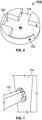
FIGs. 4-6 exemplarily illustrate various perspective views of a circular wall attachment. -
FIGs. 7-8 exemplarily illustrate various perspective views of the circular wall attachment holding a railing in place. -
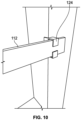
FIGs. 9-10 exemplarily illustrate various perspective views of a locking device. - In one embodiment of the present invention, a kit of parts (100) for securing railings (112) in doors and windows on the construction site, are disclosed. Referring to
FIGs. 1-3 , a perspective view of a securing device (hereinafter referred as device) (102, 104, 106, 108, 110), is illustrated. The kit ofparts 100 is used for securing or holdingrailings 112 on a construction site, comprises: a securing device (102, 104, 106, 108, 110) and a circular wall attachment (116). - The securing device (102, 104, 106, 108, 110) comprises a
rectangular opening 102 for securing rails between a pair of first outer side walls (104 and 106) and a pair of second outer side walls where each of said walls constitute a side of saidrectangular opening 102. The first pair of outer side walls (104 and 106) include one ormore protrusions 108 at both the side walls (104 and 106). The kit ofparts 100 further includes one ormore fastening holes 110 for fastening the kit ofparts 100 with the railings 112 (as shown inFIG. 1 ). The kit ofparts 100 can also be used independently on other products. The kit ofparts 100 is made of recyclable plastic material, wood and other materials. - Referring to
FIGs. 4-6 , various perspective views of acircular wall attachment 116, are illustrated. Thecircular wall attachment 116 includes acircular base 118 for being attached to awall surface 114. Thecircular base 118 includes a plurality ofsectional grooves 120 for receiving and holding therailing 112 in place in the circular base (118). Thecircular wall attachment 116 further includes one ormore fastening holes 122 for fastening with therailing 112. - Referring to
FIGs. 7-8 , various perspective views of thecircular wall attachment 116 affixed to thewall surface 112, are illustrated. Thecircular wall attachment 116 is used for holding therailing 112 in place on thewall surface 114 when in use. Therailing 112 is disposed between thesectional grooves 120 in thewall attachment 116 configured to snugly position therailing 112 in doors or windows in construction site. Thecircular wall attachment 116 can be varied according to customer's preference. - Referring to
FIGs. 9-10 , various perspective views of alocking device 124 for holding therailing 112, are illustrated. Thelocking device 124 is used for holding therailing 112 in place (as shown inFIG. 9 ). Thelocking device 124 includes asmall opening 126 and ahandle support 128 at any one end. Thelocking device 124 further includes one ormore fastening holes 130 for securing the railing (as shown inFIG. 8 ). Thelocking device 124 can be varied according to customer's preference. - Advantageously, the kit of
parts 100 of the present invention is used for securing the railing in place. Also, the kit ofparts 100 is used for securing the railing with windows and doors. The kit ofparts 100 is made of recyclable material. Further, the kit ofparts 100 is made of plastic and is cost-effective. - The foregoing examples have been provided merely for the purpose of explanation and are in no way to be construed as limiting of the present concept disclosed herein.
Claims (4)
- A kit of parts (100) for securing railings (112) in doors and windows on the construction site, comprising:a securing device (102, 104, 106, 108, 110) comprising a rectangular opening (102) for securing rails between a pair of first outer side walls (104 and 106) and a pair of second outer side walls where each of said walls constitute a side of said rectangular opening (102); wherein the first pair of outer side walls (104 and 106) include one or more protrusions (108) at both the sides walls (104 and 106); anda circular wall attachment (116) having a circular base (118) for being attached to a wall surface (114), wherein the circular wall attachment (116) holds the railing in place on the wall surface (114) when in use;
wherein the circular base (118) includes a plurality of sectional grooves (120) for receiving and holding the railing (112) in place in the circular base (118). - The kit of parts (100) of claim 1, wherein the securing device (102,104,106,108,110) further includes one or more fastening holes (110) for fastening the kit of parts (100) with the railings (112).
- The kit of parts (100) of claim 1, wherein the circular wall attachment (116) further includes one or more fastening holes (122) for fastening.
- The kit of parts (100) of claim 1, further includes a locking device (124) for holding the railing in place.
Applications Claiming Priority (1)
| Application Number | Priority Date | Filing Date | Title |
|---|---|---|---|
| DKPA202200418A DK181448B1 (en) | 2022-05-03 | 2022-05-03 | A kit of parts for securing railings on a construction site |
Publications (3)
| Publication Number | Publication Date |
|---|---|
| EP4273351A1 true EP4273351A1 (en) | 2023-11-08 |
| EP4273351B1 EP4273351B1 (en) | 2025-07-16 |
| EP4273351C0 EP4273351C0 (en) | 2025-07-16 |
Family
ID=86272205
Family Applications (1)
| Application Number | Title | Priority Date | Filing Date |
|---|---|---|---|
| EP23020196.4A Active EP4273351B1 (en) | 2022-05-03 | 2023-04-25 | A kit of parts for securing railings on a construction site |
Country Status (2)
| Country | Link |
|---|---|
| EP (1) | EP4273351B1 (en) |
| DK (1) | DK181448B1 (en) |
Citations (7)
| Publication number | Priority date | Publication date | Assignee | Title |
|---|---|---|---|---|
| US5269394A (en) * | 1992-05-20 | 1993-12-14 | Haroldson Sr Acey A | Universal bracket apparatus for attaching toe boards to scaffolds |
| US20050039402A1 (en) * | 2003-08-19 | 2005-02-24 | Innovative Safety Products Incorporated | Modular fall protection system |
| US20070246299A1 (en) * | 2006-03-31 | 2007-10-25 | Wright James E | Safety barrier stanchion |
| WO2008031902A1 (en) * | 2006-09-12 | 2008-03-20 | Vicorgilta, S.L. | Safety anchoring system for the construction of buildings |
| FR2927920A1 (en) * | 2008-02-25 | 2009-08-28 | Nord Coffrage Sa | Openings closing equipment for lift cage, during construction of building, has grid panels that are slid on each other, and panel guiding systems guiding sliding panels with respect to door frame panels |
| CA2623168A1 (en) * | 2008-03-10 | 2009-09-10 | David Vigneault | Anchorage system for handrail |
| KR100981308B1 (en) | 2009-11-23 | 2010-09-10 | 이은옥 | Safety bar for window and safety guard for window having the same |
Family Cites Families (8)
| Publication number | Priority date | Publication date | Assignee | Title |
|---|---|---|---|---|
| US5392575A (en) * | 1986-11-03 | 1995-02-28 | Hoffman; Paul | Deck construction |
| US6336620B1 (en) * | 1996-03-11 | 2002-01-08 | John A. Belli | Brackets for retaining post and board ends |
| US6305670B1 (en) * | 1996-10-22 | 2001-10-23 | Larry E. Ward | Railing assembly |
| ES1063194Y (en) * | 2006-06-21 | 2007-01-01 | Isanimar Seguridad S L | SUPPORT DEVICE FOR SECURITY RAILINGS |
| US10087651B2 (en) * | 2011-11-01 | 2018-10-02 | Snapfence Llc | Integrated snap together fence system |
| US20210189759A1 (en) * | 2018-08-02 | 2021-06-24 | Sylvain Rainville | Temporary safety guardrail for construction sites |
| KR20200098233A (en) * | 2019-02-11 | 2020-08-20 | 홍중철 | Safe apparatus for preventing fall |
| CN111779207B (en) * | 2020-07-30 | 2022-08-12 | 梅名扬 | Safety protection window fence and installation method thereof |
-
2022
- 2022-05-03 DK DKPA202200418A patent/DK181448B1/en active IP Right Grant
-
2023
- 2023-04-25 EP EP23020196.4A patent/EP4273351B1/en active Active
Patent Citations (7)
| Publication number | Priority date | Publication date | Assignee | Title |
|---|---|---|---|---|
| US5269394A (en) * | 1992-05-20 | 1993-12-14 | Haroldson Sr Acey A | Universal bracket apparatus for attaching toe boards to scaffolds |
| US20050039402A1 (en) * | 2003-08-19 | 2005-02-24 | Innovative Safety Products Incorporated | Modular fall protection system |
| US20070246299A1 (en) * | 2006-03-31 | 2007-10-25 | Wright James E | Safety barrier stanchion |
| WO2008031902A1 (en) * | 2006-09-12 | 2008-03-20 | Vicorgilta, S.L. | Safety anchoring system for the construction of buildings |
| FR2927920A1 (en) * | 2008-02-25 | 2009-08-28 | Nord Coffrage Sa | Openings closing equipment for lift cage, during construction of building, has grid panels that are slid on each other, and panel guiding systems guiding sliding panels with respect to door frame panels |
| CA2623168A1 (en) * | 2008-03-10 | 2009-09-10 | David Vigneault | Anchorage system for handrail |
| KR100981308B1 (en) | 2009-11-23 | 2010-09-10 | 이은옥 | Safety bar for window and safety guard for window having the same |
Also Published As
| Publication number | Publication date |
|---|---|
| DK181448B1 (en) | 2024-01-24 |
| EP4273351B1 (en) | 2025-07-16 |
| DK202200418A1 (en) | 2024-01-24 |
| EP4273351C0 (en) | 2025-07-16 |
Similar Documents
| Publication | Publication Date | Title |
|---|---|---|
| US6666298B2 (en) | Hanging scaffold support | |
| US2321916A (en) | Scaffold ledger bracket | |
| US4199907A (en) | Panel joint | |
| US4677791A (en) | Adjustable gate for doorways | |
| EA004844B1 (en) | Undercut anchoring element for fixing plates and/or tiles | |
| CA2104724C (en) | Scaffold bracket | |
| EP4273351A1 (en) | A kit of parts for securing railings on a construction site | |
| CA2353337A1 (en) | Bracket for supporting temporary barrier | |
| US5131505A (en) | Guide rail system for elevators | |
| JPH08326296A (en) | Flexible temporary skirting board | |
| CA2196515C (en) | Drawer | |
| US5409082A (en) | Plank support jacket | |
| JP3777190B1 (en) | Scaffolding brackets for scaffolding | |
| JP3133662U (en) | Partition plate fixture | |
| EP2117093A1 (en) | Attachment system for a support bracket of cable carrier system to a threaded bar anchorable to a ceiling | |
| US6536984B1 (en) | Taper lock fastening bracket system and method of assembly | |
| US20050039402A1 (en) | Modular fall protection system | |
| US20220220766A1 (en) | Safety rail mounting bracket system | |
| US12448779B2 (en) | Brackets for attachment of posts to joists | |
| CA1299002C (en) | Anchor for temporary fence | |
| JPH0519084Y2 (en) | ||
| JP3267913B2 (en) | Mounting structure for building decorative covers | |
| WO2025165747A1 (en) | Roof perimeter safety rail system | |
| KR200428552Y1 (en) | Fixed shoe for ascending temporary stand | |
| JPS592063Y2 (en) | Safety device at elevator entrance/exit |
Legal Events
| Date | Code | Title | Description |
|---|---|---|---|
| PUAI | Public reference made under article 153(3) epc to a published international application that has entered the european phase |
Free format text: ORIGINAL CODE: 0009012 |
|
| STAA | Information on the status of an ep patent application or granted ep patent |
Free format text: STATUS: REQUEST FOR EXAMINATION WAS MADE |
|
| 17P | Request for examination filed |
Effective date: 20230501 |
|
| AK | Designated contracting states |
Kind code of ref document: A1 Designated state(s): AL AT BE BG CH CY CZ DE DK EE ES FI FR GB GR HR HU IE IS IT LI LT LU LV MC ME MK MT NL NO PL PT RO RS SE SI SK SM TR |
|
| RIN1 | Information on inventor provided before grant (corrected) |
Inventor name: NIELSEN, CLAUS NEUMANN |
|
| GRAP | Despatch of communication of intention to grant a patent |
Free format text: ORIGINAL CODE: EPIDOSNIGR1 |
|
| STAA | Information on the status of an ep patent application or granted ep patent |
Free format text: STATUS: GRANT OF PATENT IS INTENDED |
|
| RIC1 | Information provided on ipc code assigned before grant |
Ipc: E04G 21/32 20060101ALI20250211BHEP Ipc: E04G 21/24 20060101AFI20250211BHEP |
|
| INTG | Intention to grant announced |
Effective date: 20250224 |
|
| GRAS | Grant fee paid |
Free format text: ORIGINAL CODE: EPIDOSNIGR3 |
|
| GRAA | (expected) grant |
Free format text: ORIGINAL CODE: 0009210 |
|
| STAA | Information on the status of an ep patent application or granted ep patent |
Free format text: STATUS: THE PATENT HAS BEEN GRANTED |
|
| AK | Designated contracting states |
Kind code of ref document: B1 Designated state(s): AL AT BE BG CH CY CZ DE DK EE ES FI FR GB GR HR HU IE IS IT LI LT LU LV MC ME MK MT NL NO PL PT RO RS SE SI SK SM TR |
|
| REG | Reference to a national code |
Ref country code: GB Ref legal event code: FG4D |
|
| REG | Reference to a national code |
Ref country code: CH Ref legal event code: EP Ref country code: DE Ref legal event code: R096 Ref document number: 602023004743 Country of ref document: DE |
|
| REG | Reference to a national code |
Ref country code: IE Ref legal event code: FG4D |
|
| U01 | Request for unitary effect filed |
Effective date: 20250812 |
|
| U07 | Unitary effect registered |
Designated state(s): AT BE BG DE DK EE FI FR IT LT LU LV MT NL PT RO SE SI Effective date: 20250821 |
|
| PG25 | Lapsed in a contracting state [announced via postgrant information from national office to epo] |
Ref country code: IS Free format text: LAPSE BECAUSE OF FAILURE TO SUBMIT A TRANSLATION OF THE DESCRIPTION OR TO PAY THE FEE WITHIN THE PRESCRIBED TIME-LIMIT Effective date: 20251116 |
|
| PG25 | Lapsed in a contracting state [announced via postgrant information from national office to epo] |
Ref country code: NO Free format text: LAPSE BECAUSE OF FAILURE TO SUBMIT A TRANSLATION OF THE DESCRIPTION OR TO PAY THE FEE WITHIN THE PRESCRIBED TIME-LIMIT Effective date: 20251016 |
|
| PG25 | Lapsed in a contracting state [announced via postgrant information from national office to epo] |
Ref country code: HR Free format text: LAPSE BECAUSE OF FAILURE TO SUBMIT A TRANSLATION OF THE DESCRIPTION OR TO PAY THE FEE WITHIN THE PRESCRIBED TIME-LIMIT Effective date: 20250716 |
|
| PG25 | Lapsed in a contracting state [announced via postgrant information from national office to epo] |
Ref country code: GR Free format text: LAPSE BECAUSE OF FAILURE TO SUBMIT A TRANSLATION OF THE DESCRIPTION OR TO PAY THE FEE WITHIN THE PRESCRIBED TIME-LIMIT Effective date: 20251017 |
|
| PG25 | Lapsed in a contracting state [announced via postgrant information from national office to epo] |
Ref country code: PL Free format text: LAPSE BECAUSE OF FAILURE TO SUBMIT A TRANSLATION OF THE DESCRIPTION OR TO PAY THE FEE WITHIN THE PRESCRIBED TIME-LIMIT Effective date: 20250716 |
|
| PG25 | Lapsed in a contracting state [announced via postgrant information from national office to epo] |
Ref country code: RS Free format text: LAPSE BECAUSE OF FAILURE TO SUBMIT A TRANSLATION OF THE DESCRIPTION OR TO PAY THE FEE WITHIN THE PRESCRIBED TIME-LIMIT Effective date: 20251016 |
|
| PG25 | Lapsed in a contracting state [announced via postgrant information from national office to epo] |
Ref country code: ES Free format text: LAPSE BECAUSE OF FAILURE TO SUBMIT A TRANSLATION OF THE DESCRIPTION OR TO PAY THE FEE WITHIN THE PRESCRIBED TIME-LIMIT Effective date: 20250716 |
|
| PG25 | Lapsed in a contracting state [announced via postgrant information from national office to epo] |
Ref country code: SM Free format text: LAPSE BECAUSE OF FAILURE TO SUBMIT A TRANSLATION OF THE DESCRIPTION OR TO PAY THE FEE WITHIN THE PRESCRIBED TIME-LIMIT Effective date: 20250716 |
|
| PG25 | Lapsed in a contracting state [announced via postgrant information from national office to epo] |
Ref country code: CZ Free format text: LAPSE BECAUSE OF FAILURE TO SUBMIT A TRANSLATION OF THE DESCRIPTION OR TO PAY THE FEE WITHIN THE PRESCRIBED TIME-LIMIT Effective date: 20250716 |
|
| PG25 | Lapsed in a contracting state [announced via postgrant information from national office to epo] |
Ref country code: SK Free format text: LAPSE BECAUSE OF FAILURE TO SUBMIT A TRANSLATION OF THE DESCRIPTION OR TO PAY THE FEE WITHIN THE PRESCRIBED TIME-LIMIT Effective date: 20250716 |