EP4273048A1 - Apparatus for detecting turbulence - Google Patents
Apparatus for detecting turbulence Download PDFInfo
- Publication number
- EP4273048A1 EP4273048A1 EP23168735.1A EP23168735A EP4273048A1 EP 4273048 A1 EP4273048 A1 EP 4273048A1 EP 23168735 A EP23168735 A EP 23168735A EP 4273048 A1 EP4273048 A1 EP 4273048A1
- Authority
- EP
- European Patent Office
- Prior art keywords
- aircraft
- computing system
- measured value
- turbulence
- classified
- Prior art date
- Legal status (The legal status is an assumption and is not a legal conclusion. Google has not performed a legal analysis and makes no representation as to the accuracy of the status listed.)
- Granted
Links
Images
Classifications
-
- B—PERFORMING OPERATIONS; TRANSPORTING
- B64—AIRCRAFT; AVIATION; COSMONAUTICS
- B64D—EQUIPMENT FOR FITTING IN OR TO AIRCRAFT; FLIGHT SUITS; PARACHUTES; ARRANGEMENT OR MOUNTING OF POWER PLANTS OR PROPULSION TRANSMISSIONS IN AIRCRAFT
- B64D43/00—Arrangements or adaptations of instruments
-
- G—PHYSICS
- G08—SIGNALLING
- G08G—TRAFFIC CONTROL SYSTEMS
- G08G5/00—Traffic control systems for aircraft
- G08G5/50—Navigation or guidance aids
- G08G5/55—Navigation or guidance aids for a single aircraft
-
- G—PHYSICS
- G05—CONTROLLING; REGULATING
- G05D—SYSTEMS FOR CONTROLLING OR REGULATING NON-ELECTRIC VARIABLES
- G05D1/00—Control of position, course, altitude or attitude of land, water, air or space vehicles, e.g. using automatic pilots
- G05D1/0011—Control of position, course, altitude or attitude of land, water, air or space vehicles, e.g. using automatic pilots associated with a remote control arrangement
- G05D1/0022—Control of position, course, altitude or attitude of land, water, air or space vehicles, e.g. using automatic pilots associated with a remote control arrangement characterised by the communication link
-
- G—PHYSICS
- G08—SIGNALLING
- G08G—TRAFFIC CONTROL SYSTEMS
- G08G5/00—Traffic control systems for aircraft
- G08G5/50—Navigation or guidance aids
- G08G5/57—Navigation or guidance aids for unmanned aircraft
-
- G—PHYSICS
- G08—SIGNALLING
- G08G—TRAFFIC CONTROL SYSTEMS
- G08G5/00—Traffic control systems for aircraft
- G08G5/70—Arrangements for monitoring traffic-related situations or conditions
- G08G5/76—Arrangements for monitoring traffic-related situations or conditions for monitoring atmospheric conditions
-
- B—PERFORMING OPERATIONS; TRANSPORTING
- B64—AIRCRAFT; AVIATION; COSMONAUTICS
- B64D—EQUIPMENT FOR FITTING IN OR TO AIRCRAFT; FLIGHT SUITS; PARACHUTES; ARRANGEMENT OR MOUNTING OF POWER PLANTS OR PROPULSION TRANSMISSIONS IN AIRCRAFT
- B64D45/00—Aircraft indicators or protectors not otherwise provided for
- B64D2045/009—Fire detection or protection; Erosion protection, e.g. from airborne particles
-
- B—PERFORMING OPERATIONS; TRANSPORTING
- B64—AIRCRAFT; AVIATION; COSMONAUTICS
- B64D—EQUIPMENT FOR FITTING IN OR TO AIRCRAFT; FLIGHT SUITS; PARACHUTES; ARRANGEMENT OR MOUNTING OF POWER PLANTS OR PROPULSION TRANSMISSIONS IN AIRCRAFT
- B64D45/00—Aircraft indicators or protectors not otherwise provided for
-
- B—PERFORMING OPERATIONS; TRANSPORTING
- B64—AIRCRAFT; AVIATION; COSMONAUTICS
- B64U—UNMANNED AERIAL VEHICLES [UAV]; EQUIPMENT THEREFOR
- B64U2201/00—UAVs characterised by their flight controls
- B64U2201/20—Remote controls
-
- G—PHYSICS
- G01—MEASURING; TESTING
- G01W—METEOROLOGY
- G01W1/00—Meteorology
- G01W2001/003—Clear air turbulence detection or forecasting, e.g. for aircrafts
Definitions
- the present description relates to an apparatus for detecting and evaluating turbulence, and to an aircraft, in particular an unmanned aircraft, having such an apparatus.
- Turbulence sometimes has an undesirable effect on the structure of an aircraft, and it may be necessary to adapt a flight path in order to avoid turbulence or to adapt the flight state in order to orient the aircraft, in particular as regards the angle of incidence of the aircraft, so that a load on the structure of the aircraft is kept within specific limit values.
- Manned aircraft are generally controlled by a person who is in the aircraft. That person is thus able to experience possible turbulence and the current effects thereof on the aircraft through his own sensory impressions.
- the apparatus has a first measuring device, a second measuring device and a computing system.
- the first measuring device is configured to acquire and output a first measured value, which is indicative of a movement of the aircraft relative to the earth.
- the second measuring device is configured to acquire and output a second measured value, which is indicative of a movement of the aircraft relative to the air.
- the computing system is in communicative connection with the first measuring device and with the second measuring device and is configured to receive the first measured value and the second measured value.
- the computing system is configured to determine a difference between the first measured value and the second measured value and, on the basis of the difference, to determine a turbulence intensity.
- the computing system is configured to compare the second measured value with a predefined value range for the second measured value and to class turbulence as classified turbulence if the second measured value lies outside the predefined value range, wherein the computing system is configured to determine the frequency of occurrence of such classified turbulences.
- the computing system is configured to detect a turbulent flight state on the basis of the determined turbulence intensity and the frequency of occurrence of the classified turbulences and to transmit information indicative of the turbulent flight state to an operating unit.
- the first measuring device and the second measuring device can each be in the form of a sensor, or they can also receive information and, on the basis of that information, perform an operation in order to determine and provide the measured value. If the measuring devices are in the form of sensors, then they generally acquire a physical measured variable and output a signal which correlates with the measured variable and is indicative of the measured parameter.
- Each measuring device can be in communicative connection with the computing system wirelessly or in a wired manner in order to transmit its own measured value to the computing system.
- the measuring devices can spontaneously transmit a measured value to the computing system at regular or irregular time intervals, or the computing system interrogates each measuring device.
- the wind strength is determined from the difference between the first and second measured values, that is to say from the difference between the movement of the aircraft relative to the earth and the movement of the aircraft relative to the air.
- the turbulence intensity is determined from the variation of the wind over time in terms of amplitude and direction.
- the computing system compares the second measured value with a predefined value range for the second measured value. Instead of the second measured value, a quantity derived therefrom can also be used. If the second measured value lies outside the predefined value range, turbulence is classed as classified turbulence. The computing system further determines the frequency of occurrence of such classified turbulences.
- the angle of incidence and the angle of yaw are used in this step.
- the angle of incidence defines an angle between the direction of an oncoming fluid and the chord of a profile, for example the aerofoil.
- the angle of yaw defines a drift angle between the longitudinal axis of an aircraft and the direction of the oncoming flow speed.
- the angle of incidence and/or the angle of yaw can be used as the above-mentioned derived quantities and can be compared with a respective value range predefined therefor. Before they are compared with the predefined value range, the angle of incidence and/or the angle of yaw can be fed to suitable signal processing by filtering. In other words, a change in the oncoming flow at the aerofoil or at the wing of the aircraft is used as an indicator for classified turbulence.
- the frequency of occurrence of the classified turbulences relates in particular to the number of classified turbulences per unit time.
- the computing system can, for example, contain a counter which counts the occurrences.
- the occurrences can be provided with a time stamp in order to determine the frequency of occurrence per unit time.
- the counter can contain a memory for the occurrences that are classed as classified turbulences, wherein the memory retains the entries for the occurrences only for a specific period of time and erases them when that period of time has elapsed, whereby the number of entries contained in the memory corresponds to the frequency of occurrence based on the time until the entries are erased from the memory.
- the first measuring device can determine the movement of the aircraft relative to the earth or another coordinate system or reference frame, for example by determining the position of the aircraft relative to the earth or to the coordinate system and a change of that position over time.
- inertial platforms and satellite-based position determination systems such as, for example, the global positioning system (GPS), Galileo or other such systems.
- the second measuring device acquires, for example, the back pressure and the oncoming flow angle of the air and in this manner determines the speed of the aircraft relative to the air.
- the second measuring device consists of a pitot tube and angle sensors for angles of incidence and yaw.
- the second measuring device can contain a plurality of individual sensors which measure the speed of the aircraft relative to the air along the three body axes (longitudinal axis, transverse axis, vertical axis), whereby the direction of movement of the relative airflow can also be determined. In this manner, it is possible to determine how turbulence affects the aircraft. This information can likewise be taken into account in order to detect a turbulent flight state and determine a suitable response.
- the apparatus described here acquires both the turbulence intensity and the frequency of occurrence of classified turbulences and, on the basis of these two characterizing values, determines a turbulent flight state. If such a turbulent flight state is detected, information thereon is transmitted to an external operating unit so that an operator is informed of the turbulent flight state and is able to take appropriate measures.
- a turbulent flight state and thus an excessive load on the structure of the aircraft can be detected with greater reliability and counter-measures can be initiated by the operator in good time, whereby the period of time for which the turbulence acts on the aircraft is reduced.
- This approach is advantageous in particular for unmanned aircraft, in the case of which an operator is located in an operating station and the effects of the turbulence on the structure of the aircraft cannot be perceived directly through sensory impressions.
- the predefined value range can, for example, describe a range of states of the aircraft and relate to a plurality of individual parameters, such as, for example, the speed relative to the earth and/or relative to the air, the angle of incidence of the aircraft, a measure of the vibrations or accelerations along the aircraft axes, etc.
- the predefined value range can describe or define this range of states by indicating for each parameter a value range within which the range of states is deemed to be normal. If at least one parameter departs from the predefined value range, a turbulence is correspondingly classed as classified turbulence.
- the value ranges can be different for different flight phases.
- a different value range for the angle of incidence can be deemed to be normal for a take-off phase of the aircraft than during high-speed flight.
- Empirical values can also be used for determining the predefined value range, in order to determine the values above which turbulence is classed as classified turbulence.
- the corresponding value ranges are usually determined before the aircraft is brought into service.
- the angle of incidence is to be understood as being the angle between the direction of the oncoming airflow and the longitudinal direction of an aircraft.
- the oncoming flow direction changes and the flow at the aerofoil is no longer uniform, which can lead to stalling and results in a high propeller load.
- the angle of incidence is preferably kept within a predefined range (it is thus checked whether the angle of incidence lies outside a predefined value range and, if that is the case, a corresponding turbulence is classed as classified turbulence). Turbulence or a gust of wind can lead to the angle of incidence moving outside the predefined range. This can be corrected, for example, by changing the speed of the aircraft.
- a turbulence can be defined taking account of the angle of incidence and the oncoming flow speed of the air, based on the aircraft, wherein the three direction components vertical, lateral, longitudinal are taken into account.
- turbulence in the vertical direction in particular can be highly relevant. It is necessary to respond appropriately to such turbulence in the vertical direction.
- the computing system is configured to determine a change over time of the difference between the first measured value and the second measured value so as to determine the turbulence intensity on the basis of the change over time.
- the change over time of the difference between the first measured value and the second measured value can indicate how the turbulence situation around the aircraft is developing.
- the change over time of the difference between the first measured value and the second measured value is an indication of the extent to which the speed of the aircraft relative to the earth changes relative to the speed of the aircraft relative to the air. This change over time of the difference is a measure of the turbulence intensity.
- the computing system is configured to determine the frequency of occurrence of the classified turbulences for different units of time.
- the frequency of occurrence of the classified turbulences can be determined for a short period of time (such as 3 minutes) and a longer period of time (such as 1 hour) in order to be able to make a more reliable assessment of the turbulence situation. It is also conceivable that the frequency of occurrence is determined for more than two periods of time, wherein each period of time differs in terms of its duration from the duration of all other periods of time.
- the detection of a turbulent flight state can be carried out more reliably.
- the computing system is configured to carry out the detection of a turbulent flight state throughout an entire operating time of the aircraft.
- the computing system thus performs the steps for detecting a turbulent flight state not only during specific flight phases but during the entire operating time, that is to say during a flight starting with take-off through the flight phase to landing. This is advantageous in particular for unmanned aircraft because monitoring of the flight state thus takes place for the entire flight phase.
- the computing system has a plurality of computing units, wherein each computing unit is configured to perform one or more functions of the computing system.
- the functions of the computing system as a whole can thus be divided between a plurality of computing units and performed by those computing units.
- the results of individual processing steps which are performed on separate computing units can thus be used to ultimately perform the function of the computing system as a whole.
- the functions of the computing system can be divided between existing computing units. When the functions are divided between a plurality of computing units, at least some of the functions can be performed simultaneously, in order to benefit from the advantages of the parallel performance of computing operations.
- At least two of the plurality of computing units are spatially and structurally separate from one another.
- the computing units can, for example, be arranged in different functional groups of the apparatus and/or of the aircraft.
- a first computing unit is connected to the first measuring device and is configured to determine the turbulence intensity
- a second computing unit is connected to the second measuring device and is configured to determine the frequency of occurrence of the classified turbulences.
- Further computing units which perform the remaining functions of the computing system can be provided, for example a computing unit which detects the turbulent flight state on the basis of the output values of the first and second computing units can be provided.
- an aircraft which contains an apparatus as described herein.
- the apparatus is installed in the aircraft, or the functions of the computing system are implemented on existing computing units and are performed thereby, wherein the computing units perform the functions using measured values of measuring devices arranged in the aircraft.
- the apparatus is coupled with a drive unit of the aircraft, and the computing system is configured to generate and output a control command for the drive unit if a turbulent flight state has been detected and to change a speed of the aircraft by means of the control command.
- the computing system can be configured to automatically adapt the speed of the aircraft to the detected turbulence so that the load on the structure of the aircraft due to the turbulence is kept within an allowable value range.
- the computing system can here generate commands to increase or lower the speed of the aircraft, whereby the angle of incidence of the aircraft, for example, is also adapted.
- the angle of incidence in particular can be adapted under the given conditions, that is to say taking account of the turbulence intensity, the frequency of occurrence of classified turbulences and the presence of a turbulent flight state, in order to reduce the structural load on the aircraft under the given conditions.
- the aircraft is an unmanned aircraft which can be connected by way of a wireless data transmission channel to an operating station so as to be remotely piloted by an operator.
- the aircraft can be, for example, a drone which is controlled by a human operator who, at a distance from the drone in the operating station, receives information about the drone at an operating unit and can input control commands.
- the drone transmits information about its own flight state to the operating station using a data transmission channel and receives the control commands by way of the same data transmission channel.
- the drone has an antenna or other air interface which establishes and maintains the data transmission channel with a counterpart station at the operating station.
- the apparatus described herein makes it possible, in connection with an unmanned aircraft, to reduce the structural load, because the detection of turbulence and the effect thereof on the aircraft is improved by the approach described herein. As a result, the time for which the unmanned aircraft is exposed to turbulence can be reduced.
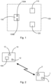
- Fig. 1 shows an apparatus 100 for detecting turbulence, marked by the dashed box.
- the apparatus 100 has a computing system 130.
- the computing system 130 in turn has a first computing unit 130A and a second computing unit 130B.
- the apparatus 100 further has a first measuring device 110 and a second measuring device 120.
- the components of the apparatus 100 that are shown are preferably arranged in an aircraft 10 (see fig. 2 ).
- the components 110, 120, 130A and 130B can be spatially and structurally separate from one another and can be so connected to one another by means of data transmission connections that measured values are transmitted from the measuring devices 110, 120 to the individual computing units of the computing system 130 and/or results of individual functions can be communicated between the computing units.
- the computing system 130 which is in communicative connection with the first measuring device 110 and with the second measuring device 120, is configured to receive the first measured value and the second measured value from the two measuring devices 110, 120.
- the computing system 130 determines a difference between the first measured value and the second measured value, in particular a change over time of that difference, in order to determine a turbulence intensity on the basis of the difference, or of the change over time of the difference.
- the computing system 130 compares the second measured value with a predefined value range for the second measured value and classes turbulence as classified turbulence if the second measured value lies outside the predefined value range.
- the computing system 130 further determines a frequency of occurrence of such classified turbulences.
- the computing system 130 detects a turbulent flight state on the basis of the determined turbulence intensity and the frequency of occurrence of the classified turbulences and transmits information indicative of the turbulent flight state to an operating unit 3 (see fig. 2 ).
- Fig. 2 shows an aircraft 10 in conjunction with an operating station 1.
- the aircraft 10 has an apparatus 100 for detecting turbulence as described in fig. 1 .
- the aircraft 10 additionally has a drive unit 13 and a communication interface 12.
- the operating station 1 is usually a stationary unit which is arranged on the ground and has a communication interface 2 and an operating unit 3.
- a wireless data transmission channel 20 is established between the communication interface 2 and the communication interface 12.
- the aircraft 10 transmits information indicative of a turbulent flight state to the operating unit 3.
- An operator is associated with the operating unit 3.
- the information about the flight state of the aircraft 10 is displayed to the operator, for example by way of a display.
- the operating unit 3 additionally also has input elements by way of which the operator is able to input commands, which are transmitted to the aircraft by way of the channel 20.
- an operator is able to respond appropriately to a detected flight state of the aircraft 10 and input and transmit to the aircraft 10 the suitable commands, for example to increase or reduce the speed, change the flight direction, etc.
- the operator is spatially separate from the aircraft 10, it is expedient and relevant if the operator receives information about a turbulent flight state that is as reliable and accurate as possible, in order that he can respond appropriately thereto even though the operator does not himself experience any sensory impressions of the flight state.
Landscapes
- Engineering & Computer Science (AREA)
- Aviation & Aerospace Engineering (AREA)
- Physics & Mathematics (AREA)
- General Physics & Mathematics (AREA)
- Radar, Positioning & Navigation (AREA)
- Remote Sensing (AREA)
- Automation & Control Theory (AREA)
- Traffic Control Systems (AREA)
- Radar Systems Or Details Thereof (AREA)
- Life Sciences & Earth Sciences (AREA)
- Atmospheric Sciences (AREA)
Abstract
Description
- The present description relates to an apparatus for detecting and evaluating turbulence, and to an aircraft, in particular an unmanned aircraft, having such an apparatus.
- During a flying phase, aircraft are exposed to external influences due to the weather and the atmosphere. Such influences are, for example, winds, which change over time. These processes of change are referred to as turbulence. Turbulence sometimes has an undesirable effect on the structure of an aircraft, and it may be necessary to adapt a flight path in order to avoid turbulence or to adapt the flight state in order to orient the aircraft, in particular as regards the angle of incidence of the aircraft, so that a load on the structure of the aircraft is kept within specific limit values.
- Manned aircraft are generally controlled by a person who is in the aircraft. That person is thus able to experience possible turbulence and the current effects thereof on the aircraft through his own sensory impressions.
- In order to forecast turbulence, aircraft are equipped with corresponding technical apparatuses. These make it possible to detect and indicate areas of adverse weather, so that a flight path can be adapted if necessary and the area of adverse weather can be avoided. Such an apparatus is described, for example, in
US 2008/021601 A1 , which describes an apparatus and a method for detecting air turbulence in the environment of an aircraft. - It can be considered as the object to improve the operation of an unmanned aircraft so as to make it easier for an operator to respond appropriately to possible turbulence.
- This object is achieved by the subject-matter of the independent claim. Further embodiments will become apparent from the dependent claims and from the following description.
- An apparatus for detecting turbulence for an aircraft is provided. The apparatus has a first measuring device, a second measuring device and a computing system. The first measuring device is configured to acquire and output a first measured value, which is indicative of a movement of the aircraft relative to the earth. The second measuring device is configured to acquire and output a second measured value, which is indicative of a movement of the aircraft relative to the air. The computing system is in communicative connection with the first measuring device and with the second measuring device and is configured to receive the first measured value and the second measured value. The computing system is configured to determine a difference between the first measured value and the second measured value and, on the basis of the difference, to determine a turbulence intensity. The computing system is configured to compare the second measured value with a predefined value range for the second measured value and to class turbulence as classified turbulence if the second measured value lies outside the predefined value range, wherein the computing system is configured to determine the frequency of occurrence of such classified turbulences. The computing system is configured to detect a turbulent flight state on the basis of the determined turbulence intensity and the frequency of occurrence of the classified turbulences and to transmit information indicative of the turbulent flight state to an operating unit.
- The first measuring device and the second measuring device can each be in the form of a sensor, or they can also receive information and, on the basis of that information, perform an operation in order to determine and provide the measured value. If the measuring devices are in the form of sensors, then they generally acquire a physical measured variable and output a signal which correlates with the measured variable and is indicative of the measured parameter.
- Each measuring device can be in communicative connection with the computing system wirelessly or in a wired manner in order to transmit its own measured value to the computing system. The measuring devices can spontaneously transmit a measured value to the computing system at regular or irregular time intervals, or the computing system interrogates each measuring device.
- The wind strength is determined from the difference between the first and second measured values, that is to say from the difference between the movement of the aircraft relative to the earth and the movement of the aircraft relative to the air. The turbulence intensity is determined from the variation of the wind over time in terms of amplitude and direction.
- The computing system compares the second measured value with a predefined value range for the second measured value. Instead of the second measured value, a quantity derived therefrom can also be used. If the second measured value lies outside the predefined value range, turbulence is classed as classified turbulence. The computing system further determines the frequency of occurrence of such classified turbulences.
- In one example, the angle of incidence and the angle of yaw are used in this step. The angle of incidence defines an angle between the direction of an oncoming fluid and the chord of a profile, for example the aerofoil. The angle of yaw defines a drift angle between the longitudinal axis of an aircraft and the direction of the oncoming flow speed. The angle of incidence and/or the angle of yaw can be used as the above-mentioned derived quantities and can be compared with a respective value range predefined therefor. Before they are compared with the predefined value range, the angle of incidence and/or the angle of yaw can be fed to suitable signal processing by filtering. In other words, a change in the oncoming flow at the aerofoil or at the wing of the aircraft is used as an indicator for classified turbulence.
- The frequency of occurrence of the classified turbulences relates in particular to the number of classified turbulences per unit time. The computing system can, for example, contain a counter which counts the occurrences. The occurrences can be provided with a time stamp in order to determine the frequency of occurrence per unit time. Alternatively, the counter can contain a memory for the occurrences that are classed as classified turbulences, wherein the memory retains the entries for the occurrences only for a specific period of time and erases them when that period of time has elapsed, whereby the number of entries contained in the memory corresponds to the frequency of occurrence based on the time until the entries are erased from the memory.
- The first measuring device can determine the movement of the aircraft relative to the earth or another coordinate system or reference frame, for example by determining the position of the aircraft relative to the earth or to the coordinate system and a change of that position over time. There can be used for this purpose, for example, inertial platforms and satellite-based position determination systems, such as, for example, the global positioning system (GPS), Galileo or other such systems.
- The second measuring device acquires, for example, the back pressure and the oncoming flow angle of the air and in this manner determines the speed of the aircraft relative to the air. For example, the second measuring device consists of a pitot tube and angle sensors for angles of incidence and yaw. The second measuring device can contain a plurality of individual sensors which measure the speed of the aircraft relative to the air along the three body axes (longitudinal axis, transverse axis, vertical axis), whereby the direction of movement of the relative airflow can also be determined. In this manner, it is possible to determine how turbulence affects the aircraft. This information can likewise be taken into account in order to detect a turbulent flight state and determine a suitable response.
- The apparatus described here acquires both the turbulence intensity and the frequency of occurrence of classified turbulences and, on the basis of these two characterizing values, determines a turbulent flight state. If such a turbulent flight state is detected, information thereon is transmitted to an external operating unit so that an operator is informed of the turbulent flight state and is able to take appropriate measures. By acquiring and taking into account both the turbulence intensity and the frequency of occurrence of classified turbulences, a turbulent flight state and thus an excessive load on the structure of the aircraft can be detected with greater reliability and counter-measures can be initiated by the operator in good time, whereby the period of time for which the turbulence acts on the aircraft is reduced. This approach is advantageous in particular for unmanned aircraft, in the case of which an operator is located in an operating station and the effects of the turbulence on the structure of the aircraft cannot be perceived directly through sensory impressions.
- Whether turbulence is classed as classified turbulence follows from the comparison with the predefined value range. The predefined value range can, for example, describe a range of states of the aircraft and relate to a plurality of individual parameters, such as, for example, the speed relative to the earth and/or relative to the air, the angle of incidence of the aircraft, a measure of the vibrations or accelerations along the aircraft axes, etc. The predefined value range can describe or define this range of states by indicating for each parameter a value range within which the range of states is deemed to be normal. If at least one parameter departs from the predefined value range, a turbulence is correspondingly classed as classified turbulence. The value ranges can be different for different flight phases. For example, a different value range for the angle of incidence can be deemed to be normal for a take-off phase of the aircraft than during high-speed flight. Empirical values can also be used for determining the predefined value range, in order to determine the values above which turbulence is classed as classified turbulence. The corresponding value ranges are usually determined before the aircraft is brought into service.
- Within the context of the present description, the angle of incidence is to be understood as being the angle between the direction of the oncoming airflow and the longitudinal direction of an aircraft. In the event of turbulence, the oncoming flow direction changes and the flow at the aerofoil is no longer uniform, which can lead to stalling and results in a high propeller load. For these reasons, the angle of incidence is preferably kept within a predefined range (it is thus checked whether the angle of incidence lies outside a predefined value range and, if that is the case, a corresponding turbulence is classed as classified turbulence). Turbulence or a gust of wind can lead to the angle of incidence moving outside the predefined range. This can be corrected, for example, by changing the speed of the aircraft.
- For example, a turbulence can be defined taking account of the angle of incidence and the oncoming flow speed of the air, based on the aircraft, wherein the three direction components vertical, lateral, longitudinal are taken into account. For the question of the structural load of an aircraft, turbulence in the vertical direction in particular can be highly relevant. It is necessary to respond appropriately to such turbulence in the vertical direction.
- According to one embodiment, the computing system is configured to determine a change over time of the difference between the first measured value and the second measured value so as to determine the turbulence intensity on the basis of the change over time.
- The change over time of the difference between the first measured value and the second measured value can indicate how the turbulence situation around the aircraft is developing. In particular, the change over time of the difference between the first measured value and the second measured value is an indication of the extent to which the speed of the aircraft relative to the earth changes relative to the speed of the aircraft relative to the air. This change over time of the difference is a measure of the turbulence intensity.
- According to a further embodiment, the computing system is configured to determine the frequency of occurrence of the classified turbulences for different units of time.
- For example, the frequency of occurrence of the classified turbulences can be determined for a short period of time (such as 3 minutes) and a longer period of time (such as 1 hour) in order to be able to make a more reliable assessment of the turbulence situation. It is also conceivable that the frequency of occurrence is determined for more than two periods of time, wherein each period of time differs in terms of its duration from the duration of all other periods of time.
- By determining the frequency of occurrence of the classified turbulences for periods of time of different lengths, the detection of a turbulent flight state can be carried out more reliably.
- According to a further embodiment, the computing system is configured to carry out the detection of a turbulent flight state throughout an entire operating time of the aircraft.
- The computing system thus performs the steps for detecting a turbulent flight state not only during specific flight phases but during the entire operating time, that is to say during a flight starting with take-off through the flight phase to landing. This is advantageous in particular for unmanned aircraft because monitoring of the flight state thus takes place for the entire flight phase.
- According to a further embodiment, the computing system has a plurality of computing units, wherein each computing unit is configured to perform one or more functions of the computing system.
- The functions of the computing system as a whole can thus be divided between a plurality of computing units and performed by those computing units. The results of individual processing steps which are performed on separate computing units can thus be used to ultimately perform the function of the computing system as a whole.
- The functions of the computing system can be divided between existing computing units. When the functions are divided between a plurality of computing units, at least some of the functions can be performed simultaneously, in order to benefit from the advantages of the parallel performance of computing operations.
- According to a further embodiment, at least two of the plurality of computing units are spatially and structurally separate from one another.
- The computing units can, for example, be arranged in different functional groups of the apparatus and/or of the aircraft.
- According to a further embodiment, a first computing unit is connected to the first measuring device and is configured to determine the turbulence intensity, wherein a second computing unit is connected to the second measuring device and is configured to determine the frequency of occurrence of the classified turbulences.
- Further computing units which perform the remaining functions of the computing system can be provided, for example a computing unit which detects the turbulent flight state on the basis of the output values of the first and second computing units can be provided.
- According to a further aspect there is provided an aircraft which contains an apparatus as described herein.
- The apparatus is installed in the aircraft, or the functions of the computing system are implemented on existing computing units and are performed thereby, wherein the computing units perform the functions using measured values of measuring devices arranged in the aircraft.
- According to one embodiment, the apparatus is coupled with a drive unit of the aircraft, and the computing system is configured to generate and output a control command for the drive unit if a turbulent flight state has been detected and to change a speed of the aircraft by means of the control command.
- The computing system can be configured to automatically adapt the speed of the aircraft to the detected turbulence so that the load on the structure of the aircraft due to the turbulence is kept within an allowable value range. The computing system can here generate commands to increase or lower the speed of the aircraft, whereby the angle of incidence of the aircraft, for example, is also adapted. By adapting the speed of the aircraft, the angle of incidence in particular can be adapted under the given conditions, that is to say taking account of the turbulence intensity, the frequency of occurrence of classified turbulences and the presence of a turbulent flight state, in order to reduce the structural load on the aircraft under the given conditions.
- According to a further embodiment, the aircraft is an unmanned aircraft which can be connected by way of a wireless data transmission channel to an operating station so as to be remotely piloted by an operator.
- The aircraft can be, for example, a drone which is controlled by a human operator who, at a distance from the drone in the operating station, receives information about the drone at an operating unit and can input control commands. The drone transmits information about its own flight state to the operating station using a data transmission channel and receives the control commands by way of the same data transmission channel. For this purpose, the drone has an antenna or other air interface which establishes and maintains the data transmission channel with a counterpart station at the operating station.
- The apparatus described herein makes it possible, in connection with an unmanned aircraft, to reduce the structural load, because the detection of turbulence and the effect thereof on the aircraft is improved by the approach described herein. As a result, the time for which the unmanned aircraft is exposed to turbulence can be reduced.
- Exemplary embodiments will be discussed in greater detail hereinbelow with reference to the accompanying drawings. The illustrations are schematic and not true to scale. Identical reference signs refer to identical or similar elements. In the drawings:
- fig. 1
- shows a schematic illustration of an apparatus for detecting turbulence;
- fig. 2
- shows a schematic illustration of an aircraft having an apparatus according to
fig. 1 in conjunction with an operating station, separate from the aircraft, for remote piloting. -
Fig. 1 shows anapparatus 100 for detecting turbulence, marked by the dashed box. Theapparatus 100 has acomputing system 130. Thecomputing system 130 in turn has afirst computing unit 130A and asecond computing unit 130B. Theapparatus 100 further has afirst measuring device 110 and asecond measuring device 120. - The components of the
apparatus 100 that are shown are preferably arranged in an aircraft 10 (seefig. 2 ). Thecomponents devices computing system 130 and/or results of individual functions can be communicated between the computing units. - The
computing system 130, which is in communicative connection with thefirst measuring device 110 and with thesecond measuring device 120, is configured to receive the first measured value and the second measured value from the two measuringdevices computing system 130 determines a difference between the first measured value and the second measured value, in particular a change over time of that difference, in order to determine a turbulence intensity on the basis of the difference, or of the change over time of the difference. Thecomputing system 130 compares the second measured value with a predefined value range for the second measured value and classes turbulence as classified turbulence if the second measured value lies outside the predefined value range. Thecomputing system 130 further determines a frequency of occurrence of such classified turbulences. Thecomputing system 130 detects a turbulent flight state on the basis of the determined turbulence intensity and the frequency of occurrence of the classified turbulences and transmits information indicative of the turbulent flight state to an operating unit 3 (seefig. 2 ). -
Fig. 2 shows anaircraft 10 in conjunction with an operating station 1. Theaircraft 10 has anapparatus 100 for detecting turbulence as described infig. 1 . Theaircraft 10 additionally has adrive unit 13 and acommunication interface 12. The operating station 1 is usually a stationary unit which is arranged on the ground and has acommunication interface 2 and anoperating unit 3. - A wireless data transmission channel 20 is established between the
communication interface 2 and thecommunication interface 12. By way of the channel 20, theaircraft 10 transmits information indicative of a turbulent flight state to theoperating unit 3. An operator is associated with theoperating unit 3. The information about the flight state of theaircraft 10 is displayed to the operator, for example by way of a display. Theoperating unit 3 additionally also has input elements by way of which the operator is able to input commands, which are transmitted to the aircraft by way of the channel 20. Thus, an operator is able to respond appropriately to a detected flight state of theaircraft 10 and input and transmit to theaircraft 10 the suitable commands, for example to increase or reduce the speed, change the flight direction, etc. Specifically because the operator is spatially separate from theaircraft 10, it is expedient and relevant if the operator receives information about a turbulent flight state that is as reliable and accurate as possible, in order that he can respond appropriately thereto even though the operator does not himself experience any sensory impressions of the flight state. - In addition, it should be noted that "comprising" or "having" does not exclude any other elements or steps, and "one" or "a" does not exclude a plurality. It should further be noted that features or steps which have been described with reference to one of the above exemplary embodiments can also be used in combination with other features or steps of other exemplary embodiments described above. Reference signs in the claims are not to be regarded as a limitation.
-
- 1
- operating station
- 2
- communication interface
- 3
- operating unit
- 10
- aircraft
- 12
- communication interface
- 13
- drive unit
- 20
- wireless data transmission channel
- 100
- apparatus for detecting turbulence
- 110
- first measuring device
- 120
- second measuring device
- 130
- computing system
- 130A, B
- computing unit
Claims (10)
- An apparatus (100) for detecting turbulence for an aircraft (10), the apparatus (100) having:a first measuring device (110) for acquiring and outputting a first measured value, which is indicative of a movement of the aircraft (10) relative to the earth;a second measuring device (120) for acquiring and outputting a second measured value, which is indicative of a movement of the aircraft (10) relative to the air;a computing system (130) which is in communicative connection with the first measuring device (110) and with the second measuring device (120) and which is configured to receive the first measured value and the second measured value;wherein the computing system (130) is configured to determine a difference between the first measured value and the second measured value and, on the basis of the difference, to determine a turbulence intensity;wherein the computing system (130) is configured to compare the second measured value with a predefined value range for the second measured value and to class turbulence as classified turbulence if the second measured value lies outside the predefined value range, wherein the computing system (130) is configured to determine a frequency of occurrence of such classified turbulences;wherein the computing system (130) is configured to detect a turbulent flight state on the basis of the determined turbulence intensity and the frequency of occurrence of the classified turbulences and to transmit information indicative of the turbulent flight state to an operating unit (3).
- The apparatus (100) as claimed in claim 1,
wherein the computing system (130) is configured to determine a change over time of the difference between the first measured value and the second measured value so as to determine the turbulence intensity on the basis of the change over time. - The apparatus (100) as claimed in claim 1 or 2,
wherein the computing system (130) is configured to determine the frequency of occurrence of the classified turbulences for different units of time. - The apparatus (100) as claimed in one of the preceding claims,
wherein the computing system (130) is configured to carry out the detection of a turbulent flight state throughout an entire operating time of the aircraft (10). - The apparatus (100) as claimed in one of the preceding claims,wherein the computing system (130) has a plurality of computing units (130A, 130B);wherein each computing unit (130A, 130B) is configured to perform one or more functions of the computing system (130).
- The apparatus (100) as claimed in claim 5,
wherein at least two of the plurality of computing units (130A, 130B) are spatially and structurally separate from one another. - The apparatus (100) as claimed in claim 6,wherein a first computing unit (130A) is connected to the first measuring device (110) and is configured to determine the turbulence intensity;wherein a second computing unit (130B) is connected to the second measuring device (120) and is configured to determine the frequency of occurrence of the classified turbulences.
- An aircraft (10) having an apparatus (100) as claimed in one of the preceding claims.
- The aircraft (10) as claimed in claim 8,wherein the apparatus (100) is coupled with a drive unit (13) of the aircraft;wherein the computing system (130) is configured to generate and output a control command for the drive unit (13) if a turbulent flight state has been detected and to change a speed of the aircraft (10) by means of the control command.
- The aircraft (10) as claimed in claim 8 or 9,
wherein the aircraft (10) is an unmanned aircraft which can be connected by way of a wireless data transmission channel (20) to an operating station (1) so as to be remotely piloted by an operator.
Applications Claiming Priority (1)
| Application Number | Priority Date | Filing Date | Title |
|---|---|---|---|
| DE102022110727.2A DE102022110727B4 (en) | 2022-05-02 | 2022-05-02 | Aircraft with a device for detecting turbulence |
Publications (2)
| Publication Number | Publication Date |
|---|---|
| EP4273048A1 true EP4273048A1 (en) | 2023-11-08 |
| EP4273048B1 EP4273048B1 (en) | 2026-03-11 |
Family
ID=86095979
Family Applications (1)
| Application Number | Title | Priority Date | Filing Date |
|---|---|---|---|
| EP23168735.1A Active EP4273048B1 (en) | 2022-05-02 | 2023-04-19 | Unmanned aircraft with an apparatus for detecting turbulence |
Country Status (3)
| Country | Link |
|---|---|
| US (1) | US12592155B2 (en) |
| EP (1) | EP4273048B1 (en) |
| DE (1) | DE102022110727B4 (en) |
Citations (5)
| Publication number | Priority date | Publication date | Assignee | Title |
|---|---|---|---|---|
| EP1008867A2 (en) * | 1998-12-10 | 2000-06-14 | Honeywell Inc. | Aircraft turbulence encounter reporting system |
| US20080021601A1 (en) | 2006-07-18 | 2008-01-24 | Airbus France | Method and device for detecting air turbulence in the environment of an aircraft |
| US8005583B2 (en) * | 2006-03-30 | 2011-08-23 | Airbus France | Method and device for determining the air turbulence likely to be encountered by an aircraft |
| WO2016174618A1 (en) * | 2015-04-30 | 2016-11-03 | Evolve The Future Srl | Integrated system to determine turbulent effects, in particular in aircrafts in flight |
| US10055998B1 (en) * | 2017-08-25 | 2018-08-21 | Airbus Operations (S.A.S.) | Ground-based identification of wake turbulence encounters |
Family Cites Families (20)
| Publication number | Priority date | Publication date | Assignee | Title |
|---|---|---|---|---|
| US3272973A (en) * | 1962-08-27 | 1966-09-13 | Meteorology Res Inc | Universal turbulence indicator |
| US3875379A (en) * | 1971-05-03 | 1975-04-01 | Carl W Vietor | Terminal airways traffic control system |
| US5187477A (en) * | 1990-04-10 | 1993-02-16 | Sundstrand Corporation | Wind shear detector with slow shear bias |
| US5130712A (en) * | 1991-04-09 | 1992-07-14 | Unisys Corporation | Microburst precursor detector utilizing microwave radar |
| DE19819341C2 (en) * | 1998-04-30 | 2000-06-15 | Daimler Chrysler Aerospace | Method for reducing gust loads on an aircraft below the cruising altitude |
| FR2883983B1 (en) * | 2005-03-31 | 2007-05-11 | Airbus France Sas | METHOD AND DEVICE FOR MEASURING AIR TURBULENCE IN THE ENVIRONMENT OF AN AIRCRAFT |
| DE102005020660B4 (en) * | 2005-05-03 | 2007-10-11 | Deutsches Zentrum für Luft- und Raumfahrt e.V. | Method for reducing the turbulence and gust effects on the flight behavior of aircraft and control device therefor |
| FR2891802B1 (en) * | 2005-10-11 | 2009-03-13 | Airbus France Sas | METHOD AND DEVICE FOR ATTENUATING THE EFFECTS OF VERTICAL TURBULENCE ON AN AIRCRAFT |
| FR2927427B1 (en) * | 2008-02-11 | 2014-12-12 | Airbus France | METHOD AND APPARATUS FOR ATTENUATING AIRBORNE EFFECTS MADE BY TURBULENCE |
| FR2943423B1 (en) * | 2009-03-17 | 2011-06-24 | Airbus France | METHOD AND DEVICE FOR ESTIMATING AT AT LEAST ONE WIND CHARACTERISTIC ON AN AIRCRAFT |
| JP5398001B2 (en) * | 2009-12-07 | 2014-01-29 | 独立行政法人 宇宙航空研究開発機構 | Airborne turbulence accident prevention device |
| US8965699B2 (en) * | 2011-04-07 | 2015-02-24 | Honeywell International Inc. | Systems and methods for characterizing turbulence regions |
| EP2615026B1 (en) * | 2011-06-10 | 2018-04-04 | Airbus Defence and Space GmbH | Method and apparatus for minimizing dynamic structural loads of an aircraft |
| WO2016125139A2 (en) * | 2015-02-05 | 2016-08-11 | Yamasee Ltd. | Method and system for obtaining and presenting turbulence data via communication devices located on airplanes |
| FR3038994B1 (en) * | 2015-07-16 | 2017-07-07 | Airbus Operations Sas | SYSTEM, DEVICE AND METHOD FOR RECORDING DATA IN AN AIRCRAFT |
| EP3379259A1 (en) * | 2017-03-24 | 2018-09-26 | Airbus Operations (S.A.S) | Vertical wind sensing system |
| US20200132841A1 (en) * | 2017-06-30 | 2020-04-30 | A^3 By Airbus Llc | Systems and methods for controlling aircraft based on sensed air movement |
| US10723480B1 (en) * | 2017-10-31 | 2020-07-28 | Rockwell Collins, Inc. | System and method for prevention and recovery from high altitude stalls |
| EP3853736B1 (en) * | 2018-09-17 | 2025-10-22 | Joby Aero, Inc. | Aircraft control system |
| US11501647B2 (en) * | 2020-09-22 | 2022-11-15 | Rockwell Collins, Inc. | Estimated wake turbulence trail for aircraft system |
-
2022
- 2022-05-02 DE DE102022110727.2A patent/DE102022110727B4/en active Active
-
2023
- 2023-04-19 EP EP23168735.1A patent/EP4273048B1/en active Active
- 2023-05-01 US US18/310,026 patent/US12592155B2/en active Active
Patent Citations (5)
| Publication number | Priority date | Publication date | Assignee | Title |
|---|---|---|---|---|
| EP1008867A2 (en) * | 1998-12-10 | 2000-06-14 | Honeywell Inc. | Aircraft turbulence encounter reporting system |
| US8005583B2 (en) * | 2006-03-30 | 2011-08-23 | Airbus France | Method and device for determining the air turbulence likely to be encountered by an aircraft |
| US20080021601A1 (en) | 2006-07-18 | 2008-01-24 | Airbus France | Method and device for detecting air turbulence in the environment of an aircraft |
| WO2016174618A1 (en) * | 2015-04-30 | 2016-11-03 | Evolve The Future Srl | Integrated system to determine turbulent effects, in particular in aircrafts in flight |
| US10055998B1 (en) * | 2017-08-25 | 2018-08-21 | Airbus Operations (S.A.S.) | Ground-based identification of wake turbulence encounters |
Non-Patent Citations (1)
| Title |
|---|
| BASS E J: "Towards a pilot-centered turbulence assessment and monitoring system", DIGITAL AVIONICS SYSTEMS CONFERENCE, 1999. PROCEEDINGS. 18TH ST LOUIS, MO, USA 24-29 OCT. 1999, PISCATAWAY, NJ, USA,IEEE, US, vol. B.6-6 vol.2, 24 October 1999 (1999-10-24), pages 6.D.3 - 1, XP010501253, ISBN: 978-0-7803-5749-5, DOI: 10.1109/DASC.1999.821980 * |
Also Published As
| Publication number | Publication date |
|---|---|
| US20230351905A1 (en) | 2023-11-02 |
| US12592155B2 (en) | 2026-03-31 |
| DE102022110727B4 (en) | 2025-05-08 |
| EP4273048B1 (en) | 2026-03-11 |
| DE102022110727A1 (en) | 2023-11-02 |
Similar Documents
| Publication | Publication Date | Title |
|---|---|---|
| US8306677B2 (en) | Automatic turbulence detection method | |
| US10580312B2 (en) | Method and system for obtaining and presenting turbulence data via communication devices located on airplanes | |
| CN107980031A (en) | The system and method indicated for no sensor special and the angle of attack of aircraft information | |
| US20230331396A1 (en) | Flight control apparatus for aerial vehicle and method of operating same | |
| US10170009B2 (en) | Method for transmitting flight parameters of a lead aircraft to an intruder aircraft | |
| EP3570135A1 (en) | Optimized trajectory to noise improvement with auto-takeoff | |
| AU2017294712B2 (en) | Method and system for obtaining and presenting turbulence data via communication devices located on airplanes | |
| US8626362B2 (en) | Method and device for monitoring the speed of an aircraft | |
| US12123743B2 (en) | Methods and systems for detecting wind shear conditions in an urban airspace | |
| CN112835379A (en) | aircraft flight management system | |
| US20120303186A1 (en) | Method And System For Aiding The Piloting Of An Airplane During An Approach | |
| US10055998B1 (en) | Ground-based identification of wake turbulence encounters | |
| WO2006048674A1 (en) | Airspace separation control and collision avoidance | |
| JP2662111B2 (en) | Automatic landing guidance method for vertical take-off and landing aircraft | |
| EP3924740A2 (en) | System and method for determining wind direction and velocity measurement from altitude for an unmanned aerial vehicle | |
| EP3471081A1 (en) | Automated aircraft landing performance analysis | |
| EP3514068B1 (en) | Aircraft speed information providing system, speed information providing method, and program | |
| EP4273048B1 (en) | Unmanned aircraft with an apparatus for detecting turbulence | |
| EP3462178B1 (en) | Low profile air data architecture | |
| CN111204467A (en) | Method and system for identifying and displaying suspicious aircraft | |
| US10921457B2 (en) | Method and device for detecting a fault of a barometric pressure measuring system arranged aboard a flying device | |
| JP5549089B2 (en) | Object dropping device and object dropping system for moving object | |
| CN119596999A (en) | A method and platform for controlling unmanned aerial vehicles over long distances | |
| EP4553468A1 (en) | Gas leakage monitoring method, gas leakage monitoring system, and gas leakage monitoring program | |
| CN115826602A (en) | System and method for managing dynamic and accurate positioning of flight based on unmanned aerial vehicle |
Legal Events
| Date | Code | Title | Description |
|---|---|---|---|
| PUAI | Public reference made under article 153(3) epc to a published international application that has entered the european phase |
Free format text: ORIGINAL CODE: 0009012 |
|
| STAA | Information on the status of an ep patent application or granted ep patent |
Free format text: STATUS: THE APPLICATION HAS BEEN PUBLISHED |
|
| AK | Designated contracting states |
Kind code of ref document: A1 Designated state(s): AL AT BE BG CH CY CZ DE DK EE ES FI FR GB GR HR HU IE IS IT LI LT LU LV MC ME MK MT NL NO PL PT RO RS SE SI SK SM TR |
|
| STAA | Information on the status of an ep patent application or granted ep patent |
Free format text: STATUS: REQUEST FOR EXAMINATION WAS MADE |
|
| 17P | Request for examination filed |
Effective date: 20240506 |
|
| RBV | Designated contracting states (corrected) |
Designated state(s): AL AT BE BG CH CY CZ DE DK EE ES FI FR GB GR HR HU IE IS IT LI LT LU LV MC ME MK MT NL NO PL PT RO RS SE SI SK SM TR |
|
| STAA | Information on the status of an ep patent application or granted ep patent |
Free format text: STATUS: EXAMINATION IS IN PROGRESS |
|
| 17Q | First examination report despatched |
Effective date: 20250303 |
|
| GRAP | Despatch of communication of intention to grant a patent |
Free format text: ORIGINAL CODE: EPIDOSNIGR1 |
|
| STAA | Information on the status of an ep patent application or granted ep patent |
Free format text: STATUS: GRANT OF PATENT IS INTENDED |
|
| INTG | Intention to grant announced |
Effective date: 20251015 |
|
| GRAS | Grant fee paid |
Free format text: ORIGINAL CODE: EPIDOSNIGR3 |
|
| GRAA | (expected) grant |
Free format text: ORIGINAL CODE: 0009210 |
|
| STAA | Information on the status of an ep patent application or granted ep patent |
Free format text: STATUS: THE PATENT HAS BEEN GRANTED |
|
| AK | Designated contracting states |
Kind code of ref document: B1 Designated state(s): AL AT BE BG CH CY CZ DE DK EE ES FI FR GB GR HR HU IE IS IT LI LT LU LV MC ME MK MT NL NO PL PT RO RS SE SI SK SM TR |
|
| REG | Reference to a national code |
Ref country code: CH Ref legal event code: F10 Free format text: ST27 STATUS EVENT CODE: U-0-0-F10-F00 (AS PROVIDED BY THE NATIONAL OFFICE) Effective date: 20260311 Ref country code: GB Ref legal event code: FG4D |
|
| REG | Reference to a national code |
Ref country code: DE Ref legal event code: R096 Ref document number: 602023013208 Country of ref document: DE |
|
| REG | Reference to a national code |
Ref country code: IE Ref legal event code: FG4D |