EP4273003B1 - Replacement mirror system with ir led overheating management - Google Patents
Replacement mirror system with ir led overheating management Download PDFInfo
- Publication number
- EP4273003B1 EP4273003B1 EP23190391.5A EP23190391A EP4273003B1 EP 4273003 B1 EP4273003 B1 EP 4273003B1 EP 23190391 A EP23190391 A EP 23190391A EP 4273003 B1 EP4273003 B1 EP 4273003B1
- Authority
- EP
- European Patent Office
- Prior art keywords
- led
- controller
- camera
- metallic
- housing
- Prior art date
- Legal status (The legal status is an assumption and is not a legal conclusion. Google has not performed a legal analysis and makes no representation as to the accuracy of the status listed.)
- Active
Links
Images


Classifications
-
- B—PERFORMING OPERATIONS; TRANSPORTING
- B60—VEHICLES IN GENERAL
- B60R—VEHICLES, VEHICLE FITTINGS, OR VEHICLE PARTS, NOT OTHERWISE PROVIDED FOR
- B60R1/00—Optical viewing arrangements; Real-time viewing arrangements for drivers or passengers using optical image capturing systems, e.g. cameras or video systems specially adapted for use in or on vehicles
- B60R1/20—Real-time viewing arrangements for drivers or passengers using optical image capturing systems, e.g. cameras or video systems specially adapted for use in or on vehicles
- B60R1/30—Real-time viewing arrangements for drivers or passengers using optical image capturing systems, e.g. cameras or video systems specially adapted for use in or on vehicles providing vision in the non-visible spectrum, e.g. night or infrared vision
-
- B—PERFORMING OPERATIONS; TRANSPORTING
- B60—VEHICLES IN GENERAL
- B60R—VEHICLES, VEHICLE FITTINGS, OR VEHICLE PARTS, NOT OTHERWISE PROVIDED FOR
- B60R1/00—Optical viewing arrangements; Real-time viewing arrangements for drivers or passengers using optical image capturing systems, e.g. cameras or video systems specially adapted for use in or on vehicles
- B60R1/12—Mirror assemblies combined with other articles, e.g. clocks
-
- B—PERFORMING OPERATIONS; TRANSPORTING
- B60—VEHICLES IN GENERAL
- B60R—VEHICLES, VEHICLE FITTINGS, OR VEHICLE PARTS, NOT OTHERWISE PROVIDED FOR
- B60R1/00—Optical viewing arrangements; Real-time viewing arrangements for drivers or passengers using optical image capturing systems, e.g. cameras or video systems specially adapted for use in or on vehicles
- B60R1/20—Real-time viewing arrangements for drivers or passengers using optical image capturing systems, e.g. cameras or video systems specially adapted for use in or on vehicles
- B60R1/22—Real-time viewing arrangements for drivers or passengers using optical image capturing systems, e.g. cameras or video systems specially adapted for use in or on vehicles for viewing an area outside the vehicle, e.g. the exterior of the vehicle
- B60R1/23—Real-time viewing arrangements for drivers or passengers using optical image capturing systems, e.g. cameras or video systems specially adapted for use in or on vehicles for viewing an area outside the vehicle, e.g. the exterior of the vehicle with a predetermined field of view
- B60R1/26—Real-time viewing arrangements for drivers or passengers using optical image capturing systems, e.g. cameras or video systems specially adapted for use in or on vehicles for viewing an area outside the vehicle, e.g. the exterior of the vehicle with a predetermined field of view to the rear of the vehicle
-
- H—ELECTRICITY
- H04—ELECTRIC COMMUNICATION TECHNIQUE
- H04N—PICTORIAL COMMUNICATION, e.g. TELEVISION
- H04N23/00—Cameras or camera modules comprising electronic image sensors; Control thereof
- H04N23/56—Cameras or camera modules comprising electronic image sensors; Control thereof provided with illuminating means
-
- H—ELECTRICITY
- H05—ELECTRIC TECHNIQUES NOT OTHERWISE PROVIDED FOR
- H05B—ELECTRIC HEATING; ELECTRIC LIGHT SOURCES NOT OTHERWISE PROVIDED FOR; CIRCUIT ARRANGEMENTS FOR ELECTRIC LIGHT SOURCES, IN GENERAL
- H05B45/00—Circuit arrangements for operating light-emitting diodes [LED]
- H05B45/40—Details of LED load circuits
- H05B45/44—Details of LED load circuits with an active control inside an LED matrix
- H05B45/46—Details of LED load circuits with an active control inside an LED matrix having LEDs disposed in parallel lines
-
- B—PERFORMING OPERATIONS; TRANSPORTING
- B60—VEHICLES IN GENERAL
- B60R—VEHICLES, VEHICLE FITTINGS, OR VEHICLE PARTS, NOT OTHERWISE PROVIDED FOR
- B60R1/00—Optical viewing arrangements; Real-time viewing arrangements for drivers or passengers using optical image capturing systems, e.g. cameras or video systems specially adapted for use in or on vehicles
- B60R1/12—Mirror assemblies combined with other articles, e.g. clocks
- B60R2001/1253—Mirror assemblies combined with other articles, e.g. clocks with cameras, video cameras or video screens
-
- B—PERFORMING OPERATIONS; TRANSPORTING
- B60—VEHICLES IN GENERAL
- B60R—VEHICLES, VEHICLE FITTINGS, OR VEHICLE PARTS, NOT OTHERWISE PROVIDED FOR
- B60R2300/00—Details of viewing arrangements using cameras and displays, specially adapted for use in a vehicle
- B60R2300/10—Details of viewing arrangements using cameras and displays, specially adapted for use in a vehicle characterised by the type of camera system used
- B60R2300/103—Details of viewing arrangements using cameras and displays, specially adapted for use in a vehicle characterised by the type of camera system used using camera systems provided with artificial illumination device, e.g. IR light source
-
- B—PERFORMING OPERATIONS; TRANSPORTING
- B60—VEHICLES IN GENERAL
- B60R—VEHICLES, VEHICLE FITTINGS, OR VEHICLE PARTS, NOT OTHERWISE PROVIDED FOR
- B60R2300/00—Details of viewing arrangements using cameras and displays, specially adapted for use in a vehicle
- B60R2300/80—Details of viewing arrangements using cameras and displays, specially adapted for use in a vehicle characterised by the intended use of the viewing arrangement
- B60R2300/8046—Details of viewing arrangements using cameras and displays, specially adapted for use in a vehicle characterised by the intended use of the viewing arrangement for replacing a rear-view mirror system
-
- B—PERFORMING OPERATIONS; TRANSPORTING
- B60—VEHICLES IN GENERAL
- B60R—VEHICLES, VEHICLE FITTINGS, OR VEHICLE PARTS, NOT OTHERWISE PROVIDED FOR
- B60R2300/00—Details of viewing arrangements using cameras and displays, specially adapted for use in a vehicle
- B60R2300/80—Details of viewing arrangements using cameras and displays, specially adapted for use in a vehicle characterised by the intended use of the viewing arrangement
- B60R2300/8053—Details of viewing arrangements using cameras and displays, specially adapted for use in a vehicle characterised by the intended use of the viewing arrangement for bad weather conditions or night vision
Definitions
- This disclosure relates to a camera mirror system having night vision.
- RGB camera Some types of cameras, such as an RGB camera, will not display an image that is visible at night.
- One approach to providing a visible image at night is to illuminate the camera's field of view with infrared light-emitting diodes (IR LED).
- IR LED infrared light-emitting diodes
- IR LED systems generate heat as they consume power. If the heat is not sufficiently dissipated, an overheating condition may occur, which can cause damage to the circuitry or generate malfunctions in the system. Solutions have been proposed which cycle the IR LEDs on and off. This may be undesirable for rear facing camera mirror systems of the type employed on commercial trucks.
- EP1362741 shows a mirror with a camera system with night vision.
- a camera mirror system for a vehicle includes a camera arm.
- the camera arm has a mounting bracket that supports a camera housing.
- the camera housing includes a pivotal portion pivotably mounted to a fixed portion.
- the mounting bracket is metallic.
- the system also includes a camera that is arranged in the pivotal portion of the camera housing and includes a field of view.
- the system further includes a night vision assembly.
- the night vision assembly includes an infrared light-emitting diode (IR LED) that is configured to illuminate the field of view.
- the night vision assembly is secured to the mounting bracket.
- the night vision assembly includes a metallic housing that supports a metallic carrier.
- the IR LED is mounted to the metallic carrier.
- a front window is arranged over the IR LED and sealed relative to the metallic housing. The front window is exposed through an aperture in the camera housing.
- a printed circuit board may be arranged in the housing (e.g. metallic housing).
- the printed circuit board may be in communication with the IR LED.
- the metallic housing may be filled with potting material.
- FIG. 1 A schematic view of a commercial truck 10 is illustrated in Figure 1 .
- the truck 10 includes a vehicle cab 12 pulling a trailer 14.
- Driver and passenger side camera housings 16, provided as arms, are mounted to the vehicle cab 12. If desired, the camera housings 16 may include conventional mirrors integrated with them as well.
- First and second displays 18 are arranged on each of the driver and passenger sides within the vehicle cab 12 to display class II and class IV views on each side of the vehicle 10. Additional displays may be used, and additional or different class views may be provided by the system, if desired.
- At least one rearward facing camera 20 is arranged within the camera housing 16.
- the camera 20 includes an image capture unit 21 that provides a field of view 22 corresponding to at least one of the class II and class IV views, for example. Multiple cameras also may be used to provide the desired views. Class V and class VI views may also be desirable in order to provide views at the opposite front corner from the driver.
- IR LED infrared light-emitting diode
- a night vision assembly 23 includes a temperature sensor 27 that is provided in close proximity to IR LEDs 24, for example, on a common circuit board 29 with the IR LEDs 24 to provide a first controller 28a.
- the temperature sensor 27 is configured to measure a temperature of the IR LEDs, either directly or indirectly.
- a second controller 28b is in communication with the temperature sensor 27.
- the first and second controllers 28a, 28b may be provided on a common PCB.
- the second controller 28b includes a video processor that provides a video signal containing images from the image capture unit 21 to the display 16.
- the second controller 28b may be located within the camera housing 16 or within the display 18. In the example shown in Figure 2A , the second controller 28b is arrange in the camera housing 16.
- the second controller 28b may also be in communication with the IR LEDs 24 to command the IR LEDs on and off.
- a manual switch 30 may be used by the driver to manually turn on and off the IR LEDs 24.
- the second controller 28b is configured to provide at least one of a warning or an IR LED shut down command in response to the temperature detected by the temperature sensor 27 exceeding a temperature threshold.
- the temperature threshold corresponds to an undesired IR LED temperature at which or near the temperature that the IR LEDs 24 or associated circuitry may become damaged or malfunction.
- a warning of the undesired IR LED temperature is communicated to the driver, such as by displaying a warning symbol 32 on the display 18 or by providing another type of audio and/or visual warning elsewhere.
- FIG. 2B Another example system is shown in Figure 2B , but with the second controller 28b located outside of the camera housing 16.
- the system may function and be configured in a similar manner to the system described above in connection with Figure 2A , if desired.
- the night vision assembly 23 is mounted to a metallic mounted bracket 15 (e.g., aluminum) secured to the vehicle cab 12, as shown in Figure 3A .
- the mounting bracket 15 supports the camera housing 16, which may include a fixed potion 16a and a pivotable portion 16b.
- the camera 20 ( Figs. 2A and 2B ) is arranged in the pivotable portion 16b.
- a pivot member 17 passively or actively enables the pivotable portion 16b to rotate with respect to the fixed portion 16a.
- the night vision assembly 23, which includes the IR LEDs 24, is secured to the mounting bracket 15 to conductively dissipate heat to this large, metallic structure.
- the night vision assembly 23 includes a metallic housing 23a supporting a metallic carrier 23b, which are aluminum in one example.
- the IR LEDs 24 are mounted to the metallic carrier 23b via a metallic board 23e, and a transparent front window 23c is arranged over the IR LEDs 24 and sealed relative to the metallic housing 23a, for example, with glue.
- the front window 23c is exposed through an aperture in the fixed portion 16a so that the desired area may be illuminated with infrared light.
- the printed circuit board 29, which drives the IR LEDs 24, is arranged in the metallic housing 23a and is in communication with the IR LEDs 24.
- the metallic housing 23a is filled with potting material 23d.
- the controller 28b is configured to provide at least one of a warning or an IR LED shut down command in response to the temperature detected by the temperature sensor 27 exceeding a temperature threshold.
- the configuration shown in Figure 2B may use a simplified wiring scheme ( Fig. 3A ) in which a wire bundle 34 interconnecting the first and second controllers 28a, 28b only includes two wires 36 (ground and power) that are used to power the IR LEDs 24 via the first controller 28a.
- the second controller 28b may command the first controller 28a between multiple IR LED output levels, e.g., 100% power and 30% power, using the wire bundle 34. Since only two wires 36 are used, the second controller 28a may detect an over-temperature condition by sensing a reduction in current in the wires 36 as compared to the expected current for the commanded power level. The reduced current is interpreted by the second controller 28b as the IR LEDs being at an undesirably high temperature, and the second controller 28b may display a warning symbol 32, command the IR LEDs 24 automatically to a lower output level, and/or shut the IR LEDs 24 off.
- IR LED output levels e.g., 100% power and 30% power
- the method 40 includes powering the IR LEDs 24 when desired, as indicated at block 42. This may be performed by a light sensor automatically sensing a low light condition (block 48) and/or automatically turning on the IR LEDs 24 (e.g., with the vehicle headlights). Alternatively, the switch 30 may be used by the driver to manually turn on and off the IR LEDs 24, as indicated at block 50, whenever desired.
- the temperature sensor 27 senses the IR LED temperature, directly or indirectly, as indicated at block 44. Once the sensed temperature exceeds a threshold, as indicated at block 46, the driver may be warned, for example, by displaying a warning symbol 32 on the display 18. At this point, the driver may manually shut down the IR LEDs 24 using the switch 30, as indicated at block 52, or the IR LEDs may be automatically shut down once a second temperature threshold is exceeded, as indicated at block 54, to discontinue power to the IR LEDs 24 after a predetermined time from the warning.
- the IR LEDs 24 may also be powered at a lower output level (block 56) to reduce the wattage, thereby reducing heat production. In this manner, the integrity of the circuitry is maintained and any system malfunctions are avoided.
- the driver may be notified when the temperature has dropped sufficiently and the night vision system may be used again, or the night vision system may be automatically turned on, or output level increased, by the system.
Landscapes
- Engineering & Computer Science (AREA)
- Multimedia (AREA)
- Mechanical Engineering (AREA)
- Signal Processing (AREA)
- Studio Devices (AREA)
- Lighting Device Outwards From Vehicle And Optical Signal (AREA)
- Closed-Circuit Television Systems (AREA)
Description
- This disclosure relates to a camera mirror system having night vision.
- Some types of cameras, such as an RGB camera, will not display an image that is visible at night. One approach to providing a visible image at night is to illuminate the camera's field of view with infrared light-emitting diodes (IR LED).
- IR LED systems generate heat as they consume power. If the heat is not sufficiently dissipated, an overheating condition may occur, which can cause damage to the circuitry or generate malfunctions in the system. Solutions have been proposed which cycle the IR LEDs on and off. This may be undesirable for rear facing camera mirror systems of the type employed on commercial trucks.
EP1362741 shows a mirror with a camera system with night vision. - The present invention is defined herein in accordance with appended independent claim 1. Optional features of the invention are set out in the appended dependent claims.
- In accordance with independent claim 1, a camera mirror system for a vehicle includes a camera arm. The camera arm has a mounting bracket that supports a camera housing. The camera housing includes a pivotal portion pivotably mounted to a fixed portion. The mounting bracket is metallic. The system also includes a camera that is arranged in the pivotal portion of the camera housing and includes a field of view. The system further includes a night vision assembly. The night vision assembly includes an infrared light-emitting diode (IR LED) that is configured to illuminate the field of view. The night vision assembly is secured to the mounting bracket. The night vision assembly includes a metallic housing that supports a metallic carrier. The IR LED is mounted to the metallic carrier. A front window is arranged over the IR LED and sealed relative to the metallic housing. The front window is exposed through an aperture in the camera housing.
- In a further embodiment of the above, a printed circuit board may be arranged in the housing (e.g. metallic housing). The printed circuit board may be in communication with the IR LED. The metallic housing may be filled with potting material.
- The disclosure can be further understood by reference to the following detailed description when considered in connection with the accompanying drawings wherein:
-
Figure 1 is a schematic top elevational view of a commercial truck with class II and class IV views. -
Figure 2A is a schematic of a camera mirror system having night vision according to a first embodiment. -
Figure 2B is a schematic of another camera mirror system having night vision according to a second embodiment. -
Figure 3A is partial schematic view of a camera arm with a night vision assembly. -
Figure 3B a schematic view of a night vision assembly. -
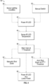
Figure 4 is a flow chart depicting an example method of managing night vision for a vehicle camera mirror system. - The embodiments, examples and alternatives of the preceding paragraphs, the claims, or the following description and drawings, including any of their various aspects or respective individual features, may be taken independently or in any combination. Features described in connection with one embodiment are applicable to all embodiments, unless such features are incompatible.
- A schematic view of a
commercial truck 10 is illustrated inFigure 1 . Thetruck 10 includes avehicle cab 12 pulling atrailer 14. Driver and passengerside camera housings 16, provided as arms, are mounted to thevehicle cab 12. If desired, thecamera housings 16 may include conventional mirrors integrated with them as well. First andsecond displays 18 are arranged on each of the driver and passenger sides within thevehicle cab 12 to display class II and class IV views on each side of thevehicle 10. Additional displays may be used, and additional or different class views may be provided by the system, if desired. - Referring to
Figures 2A and 2B , at least one rearward facingcamera 20 is arranged within thecamera housing 16. Thecamera 20 includes animage capture unit 21 that provides a field ofview 22 corresponding to at least one of the class II and class IV views, for example. Multiple cameras also may be used to provide the desired views. Class V and class VI views may also be desirable in order to provide views at the opposite front corner from the driver. - Some regulations governing mirror replacement camera systems require that certain objects be displayed to the driver in color. Some examples include stop signs and emergency lights. To this end, it is desirable to provide a night vision system that both illuminates the field of
view 22 but is also able to provide a display to the driver in the necessary colors. At least one infrared light-emitting diode (IR LED) 24, which may be provided as a light array, illuminates a field ofview 26 that overlaps the field ofview 22. - The
IR LEDs 24, when in use, consume a sufficient amount of power to generate undesired heat that can damage circuitry or generate malfunctions in the system. In one example system shown inFigure 2A , anight vision assembly 23 includes atemperature sensor 27 that is provided in close proximity toIR LEDs 24, for example, on acommon circuit board 29 with theIR LEDs 24 to provide afirst controller 28a. Thetemperature sensor 27 is configured to measure a temperature of the IR LEDs, either directly or indirectly. - A
second controller 28b is in communication with thetemperature sensor 27. In an example embodiment, the first andsecond controllers second controller 28b includes a video processor that provides a video signal containing images from theimage capture unit 21 to thedisplay 16. Depending on the desired configuration, thesecond controller 28b may be located within thecamera housing 16 or within thedisplay 18. In the example shown inFigure 2A , thesecond controller 28b is arrange in thecamera housing 16. - The
second controller 28b may also be in communication with theIR LEDs 24 to command the IR LEDs on and off. In one example, amanual switch 30 may be used by the driver to manually turn on and off theIR LEDs 24. - The
second controller 28b is configured to provide at least one of a warning or an IR LED shut down command in response to the temperature detected by thetemperature sensor 27 exceeding a temperature threshold. The temperature threshold corresponds to an undesired IR LED temperature at which or near the temperature that theIR LEDs 24 or associated circuitry may become damaged or malfunction. A warning of the undesired IR LED temperature is communicated to the driver, such as by displaying awarning symbol 32 on thedisplay 18 or by providing another type of audio and/or visual warning elsewhere. - Another example system is shown in
Figure 2B , but with thesecond controller 28b located outside of thecamera housing 16. The system may function and be configured in a similar manner to the system described above in connection withFigure 2A , if desired. - To mitigate heat issues, the
night vision assembly 23 is mounted to a metallic mounted bracket 15 (e.g., aluminum) secured to thevehicle cab 12, as shown inFigure 3A . The mountingbracket 15 supports thecamera housing 16, which may include a fixedpotion 16a and apivotable portion 16b. The camera 20 (Figs. 2A and 2B ) is arranged in thepivotable portion 16b. Apivot member 17 passively or actively enables thepivotable portion 16b to rotate with respect to the fixedportion 16a. Thenight vision assembly 23, which includes theIR LEDs 24, is secured to the mountingbracket 15 to conductively dissipate heat to this large, metallic structure. - As shown in
Figure 3B , thenight vision assembly 23 includes ametallic housing 23a supporting ametallic carrier 23b, which are aluminum in one example. TheIR LEDs 24 are mounted to themetallic carrier 23b via ametallic board 23e, and a transparentfront window 23c is arranged over theIR LEDs 24 and sealed relative to themetallic housing 23a, for example, with glue. Thefront window 23c is exposed through an aperture in the fixedportion 16a so that the desired area may be illuminated with infrared light. The printedcircuit board 29, which drives theIR LEDs 24, is arranged in themetallic housing 23a and is in communication with theIR LEDs 24. Themetallic housing 23a is filled withpotting material 23d. - The
controller 28b is configured to provide at least one of a warning or an IR LED shut down command in response to the temperature detected by thetemperature sensor 27 exceeding a temperature threshold. The configuration shown inFigure 2B may use a simplified wiring scheme (Fig. 3A ) in which awire bundle 34 interconnecting the first andsecond controllers IR LEDs 24 via thefirst controller 28a. - The
second controller 28b may command thefirst controller 28a between multiple IR LED output levels, e.g., 100% power and 30% power, using thewire bundle 34. Since only twowires 36 are used, thesecond controller 28a may detect an over-temperature condition by sensing a reduction in current in thewires 36 as compared to the expected current for the commanded power level. The reduced current is interpreted by thesecond controller 28b as the IR LEDs being at an undesirably high temperature, and thesecond controller 28b may display awarning symbol 32, command theIR LEDs 24 automatically to a lower output level, and/or shut theIR LEDs 24 off. - Referring to
Figure 4 , amethod 40 of managing night vision for a vehicle camera system is shown. Themethod 40 includes powering theIR LEDs 24 when desired, as indicated atblock 42. This may be performed by a light sensor automatically sensing a low light condition (block 48) and/or automatically turning on the IR LEDs 24 (e.g., with the vehicle headlights). Alternatively, theswitch 30 may be used by the driver to manually turn on and off theIR LEDs 24, as indicated atblock 50, whenever desired. - The
temperature sensor 27 senses the IR LED temperature, directly or indirectly, as indicated atblock 44. Once the sensed temperature exceeds a threshold, as indicated atblock 46, the driver may be warned, for example, by displaying awarning symbol 32 on thedisplay 18. At this point, the driver may manually shut down theIR LEDs 24 using theswitch 30, as indicated atblock 52, or the IR LEDs may be automatically shut down once a second temperature threshold is exceeded, as indicated atblock 54, to discontinue power to theIR LEDs 24 after a predetermined time from the warning. TheIR LEDs 24 may also be powered at a lower output level (block 56) to reduce the wattage, thereby reducing heat production. In this manner, the integrity of the circuitry is maintained and any system malfunctions are avoided. - If desired, the driver may be notified when the temperature has dropped sufficiently and the night vision system may be used again, or the night vision system may be automatically turned on, or output level increased, by the system.
- It should also be understood that although a particular component arrangement is disclosed in the illustrated embodiment, other arrangements will benefit herefrom. Although particular step sequences are shown, described, and claimed, it should be understood that steps may be performed in any order, separated or combined unless otherwise indicated and will still benefit from the present invention.
- Although the different examples have specific components shown in the illustrations, embodiments of this invention are not limited to those particular combinations. It is possible to use some of the components or features from one of the examples in combination with features or components from another one of the examples.
- Although an example embodiment has been disclosed, a worker of ordinary skill in this art would recognize that certain modifications would come within the scope of the claims. For that reason, the following claims should be studied to determine their true scope and content.
Claims (12)
- A camera mirror system for a vehicle comprising:a camera arm having a metallic mounting bracket (15) supporting a camera housing (16), the camera housing (16) including a pivotal portion (16b) pivotably mounted to a fixed portion (16a);a camera (20) arranged in the pivotal portion (16b) of the camera housing (16), the camera (20) including a field of view (22);a night vision assembly (23) including an infrared light-emitting diode (IR LED) (24) configured to illuminate the field of view (22), the night vision assembly (23) secured to the metallic bracket (15), wherein the night vision assembly includes a metallic housing (23a) supporting a metallic carrier (23b), the IR LED (24) mounted to the metallic carrier (23b), and a front window (23c) arranged over the IR LED (24) and sealed relative to the metallic housing (23a), the front window (23c) exposed through an aperture in the camera housing (16).
- The system of claim 1, wherein a printed circuit board (29) is arranged in the metallic housing (23a) and in communication with the IR LED (24), the metallic housing (23a) filled with potting material (23d).
- The system of claim 1 comprising:a display (18) in communication with the camera (20) configured to depict the field of view (22);wherein the IR LED (24) is configured to operate at a temperature;
anda controller (28b) configured to provide at least one of a warning or an IR LED shut down command in response to the temperature exceeding a threshold. - The system of claim 3, wherein the field of view (22) corresponds to one of a corner view or a rear-facing field view, wherein the display (18) is configured to display (18) at least one of class II and class IV views illuminated by the IR LED (24) for the rear-facing view, and the display (18) is configured to display (18) at least one of class V and class VI views illuminated by the IR LED (24) for the corner view.
- The system of claim 1, comprising a temperature sensor (27) configured to measure the temperature of the IR LED (24), the IR LED (24) and the temperature sensor (27) are arranged in the camera housing (16) and configured to be arranged outside of the vehicle.
- The system of claim 5, comprising a controller (28a) in communication with the temperature sensor (27) and arranged in the metallic housing (23a), the controller (28a) is a first controller, and comprising a second controller (28b) that is in communication with the camera (20), the second controller (28b) includes a video processor that is configured to provide a video signal to the display (18).
- The system of claim 3, wherein the controller (28b) is arranged outside the camera housing (16) and configured to be arranged inside the vehicle, wherein the controller (28b) is configured to sense current from the IR LED (24) and infer the temperature based upon the current.
- The system of claim 7, wherein the IR LED (24) is mounted on a first controller providing a printed circuit board (29) arranged in the metallic housing (23a), and the controller (28b) is a second controller that includes a video processor configured to provide a video signal to the display (18), the first and second controllers connected by a wire bundle (34) consisting of two wires (36), the current provided over the wires (36).
- The system of claim 8, wherein the second controller (28b) is configured to command the IR LED (24) on the first controller between multiple output levels over the wire bundle (34).
- The system of claim 3, wherein the warning corresponds to a symbol (32) on the display (18).
- The system of claim 3, comprising a switch (30), and the IR LED shut down command is provided by the switch (30), wherein the switch (30) is configured to be manually operated by a driver to turn the IR LED (24) on and off.
- The system of claim 1, wherein the metallic bracket (15) and the night vision assembly (23) are arranged in the fixed portion (16a).
Applications Claiming Priority (3)
| Application Number | Priority Date | Filing Date | Title |
|---|---|---|---|
| US201962805535P | 2019-02-14 | 2019-02-14 | |
| PCT/EP2020/053647 WO2020165282A1 (en) | 2019-02-14 | 2020-02-12 | Replacement mirror system with ir led overheating management |
| EP20705177.2A EP3924219B1 (en) | 2019-02-14 | 2020-02-12 | Replacement mirror system with ir led overheating management |
Related Parent Applications (2)
| Application Number | Title | Priority Date | Filing Date |
|---|---|---|---|
| EP20705177.2A Division EP3924219B1 (en) | 2019-02-14 | 2020-02-12 | Replacement mirror system with ir led overheating management |
| EP20705177.2A Division-Into EP3924219B1 (en) | 2019-02-14 | 2020-02-12 | Replacement mirror system with ir led overheating management |
Publications (3)
| Publication Number | Publication Date |
|---|---|
| EP4273003A2 EP4273003A2 (en) | 2023-11-08 |
| EP4273003A3 EP4273003A3 (en) | 2024-01-17 |
| EP4273003B1 true EP4273003B1 (en) | 2025-04-30 |
Family
ID=69582119
Family Applications (2)
| Application Number | Title | Priority Date | Filing Date |
|---|---|---|---|
| EP23190391.5A Active EP4273003B1 (en) | 2019-02-14 | 2020-02-12 | Replacement mirror system with ir led overheating management |
| EP20705177.2A Active EP3924219B1 (en) | 2019-02-14 | 2020-02-12 | Replacement mirror system with ir led overheating management |
Family Applications After (1)
| Application Number | Title | Priority Date | Filing Date |
|---|---|---|---|
| EP20705177.2A Active EP3924219B1 (en) | 2019-02-14 | 2020-02-12 | Replacement mirror system with ir led overheating management |
Country Status (4)
| Country | Link |
|---|---|
| US (2) | US11153950B2 (en) |
| EP (2) | EP4273003B1 (en) |
| CN (1) | CN113412210B (en) |
| WO (1) | WO2020165282A1 (en) |
Families Citing this family (10)
| Publication number | Priority date | Publication date | Assignee | Title |
|---|---|---|---|---|
| US11153950B2 (en) * | 2019-02-14 | 2021-10-19 | Orlaco Products B.V. | Replacement mirror system with IR LED overheating management |
| WO2022140161A1 (en) * | 2020-12-23 | 2022-06-30 | Stoneridge Electronics Ab | Camera mirror system with outside air temperature sensor |
| US12330564B2 (en) * | 2021-11-12 | 2025-06-17 | Stoneridge Electronics Ab | Automatic IR LED control for camera mirror system |
| US12358430B2 (en) * | 2022-06-23 | 2025-07-15 | Stoneridge Electronics Ab | Modular semi-trailer sensor suite |
| JP2026501117A (en) * | 2022-12-07 | 2026-01-14 | ストーンリッジ エレクトロニクス アーベー | Trailer Camera Display System |
| EP4638196A1 (en) * | 2022-12-20 | 2025-10-29 | Stoneridge Electronics AB | Camera mirror system with dark docking ir led |
| CN115968072A (en) * | 2022-12-28 | 2023-04-14 | 凌云光技术股份有限公司 | A lighting system and method |
| DE102023100141A1 (en) * | 2023-01-04 | 2024-07-04 | Man Truck & Bus Se | Vision system for a vehicle |
| WO2024161516A1 (en) * | 2023-01-31 | 2024-08-08 | 日産自動車株式会社 | Imaging method for vehicle and imaging system for vehicle |
| DE102023127318B4 (en) * | 2023-10-06 | 2025-04-30 | Man Truck & Bus Se | Activating and optimizing a night mode in camera monitor applications |
Family Cites Families (36)
| Publication number | Priority date | Publication date | Assignee | Title |
|---|---|---|---|---|
| ES1025450Y (en) | 1993-07-30 | 1994-07-16 | Yotam Sa | "INFRARED LIGHTING DEVICE" |
| DE19521326A1 (en) * | 1995-06-12 | 1996-12-19 | Bosch Siemens Hausgeraete | Method for temperature compensation of the measured values of a turbidity sensor in an automatic washing machine or dishwasher |
| DE29806638U1 (en) | 1997-06-18 | 1998-06-18 | Leopold Kostal GmbH & Co KG, 58507 Lüdenscheid | Camera surveillance device |
| JP2000115759A (en) | 1998-10-05 | 2000-04-21 | Sony Corp | Imaging display device |
| JP4088100B2 (en) * | 2002-05-14 | 2008-05-21 | 株式会社村上開明堂 | Rearview mirror with built-in camera |
| JP3948431B2 (en) | 2003-04-09 | 2007-07-25 | トヨタ自動車株式会社 | Vehicle periphery monitoring device |
| FR2858955B1 (en) | 2003-08-20 | 2007-09-28 | Daimler Chrysler Ag | INFRARED RAY SOURCE FOR VEHICLES ADAPTED TO AN INFRARED NIGHT VISION SYSTEM |
| JP4140898B2 (en) | 2003-08-20 | 2008-08-27 | 日本電信電話株式会社 | Information presentation device and method of using information presentation device |
| US20050243172A1 (en) * | 2004-04-30 | 2005-11-03 | Teiichiro Takano | Rear view mirror with built-in camera |
| JP4242334B2 (en) * | 2004-11-30 | 2009-03-25 | 本田技研工業株式会社 | Vehicle periphery monitoring device |
| US7821123B2 (en) * | 2005-09-13 | 2010-10-26 | Delphi Technologies, Inc. | LED array cooling system |
| JP4777759B2 (en) | 2005-12-01 | 2011-09-21 | 富士フイルム株式会社 | Wiring board and wiring board connecting device |
| JP2008124303A (en) * | 2006-11-14 | 2008-05-29 | Seiko Epson Corp | Semiconductor light emitting element drive control device, projection display device having drive control device, and methods thereof |
| US8581982B1 (en) * | 2007-07-30 | 2013-11-12 | Flir Systems, Inc. | Infrared camera vehicle integration systems and methods |
| US8340870B2 (en) * | 2008-09-16 | 2012-12-25 | Honda Motor Co., Ltd. | Vehicle maneuver assistance device |
| TWM353849U (en) * | 2008-09-17 | 2009-04-01 | Jyh-Chiang Liou | Integrated driving assistance apparatus |
| JP4951643B2 (en) * | 2009-03-19 | 2012-06-13 | 株式会社村上開明堂 | Outer mirror for vehicle |
| JP4952765B2 (en) * | 2009-10-21 | 2012-06-13 | トヨタ自動車株式会社 | Vehicle night vision support device |
| TWM378332U (en) | 2009-11-27 | 2010-04-11 | Yu De Technology Co Ltd | Infrared lighting device |
| US20110273527A1 (en) | 2010-05-06 | 2011-11-10 | Tzu-Chuan Liu | Electronic Infrared Wide-Angle and Safety-Promotion External Vehicular Back Mirror |
| TW201204988A (en) * | 2010-07-26 | 2012-02-01 | Foxsemicon Integrated Tech Inc | LED light emitting device |
| GB201103367D0 (en) * | 2011-02-28 | 2011-04-13 | 360 Vision Technology Ltd | Security camera |
| MY179271A (en) | 2011-09-27 | 2020-11-03 | Zp Enterprise Ltd | A vision enhancement system and a device therefor |
| US8816306B2 (en) * | 2011-12-15 | 2014-08-26 | Battelle Memorial Institute | Infrared light device |
| US9377355B2 (en) * | 2013-02-18 | 2016-06-28 | Eminent Electronic Technology Corp. Ltd. | Optical sensor apparatus and image sensing apparatus integrating multiple functions |
| TWI538509B (en) * | 2014-08-29 | 2016-06-11 | 晶睿通訊股份有限公司 | Camera and control method thereof |
| CN105306796A (en) | 2015-10-10 | 2016-02-03 | 安霸半导体技术(上海)有限公司 | Night vision equipment with regular infrared illumination function and global shutter CMOS (Complementary Metal Oxide Semiconductor) sensor |
| US10694107B2 (en) * | 2015-11-13 | 2020-06-23 | Albert Orglmeister | Method and device for eliminating thermal interference for infrared and video-based early fire detection |
| US11313167B2 (en) * | 2016-04-25 | 2022-04-26 | Magna Closures Inc. | System and method for detecting vehicular door movement due to non-contact using obstacle detection |
| JP6511015B2 (en) * | 2016-05-25 | 2019-05-08 | 株式会社ミツバ | Vehicle monitoring system |
| CN206164701U (en) | 2016-10-24 | 2017-05-10 | 奇瑞汽车股份有限公司 | On -vehicle infrared night -vision device |
| JP6720952B2 (en) * | 2017-11-21 | 2020-07-08 | オムロン株式会社 | Occupant monitoring device |
| JP6780671B2 (en) * | 2018-03-15 | 2020-11-04 | オムロン株式会社 | Crew monitoring device |
| US10674052B1 (en) * | 2018-12-12 | 2020-06-02 | Valeo North America, Inc. | Common cover lens for camera and illuminators |
| US11153950B2 (en) * | 2019-02-14 | 2021-10-19 | Orlaco Products B.V. | Replacement mirror system with IR LED overheating management |
| US10893175B2 (en) * | 2019-02-27 | 2021-01-12 | Bendix Commercial Vehicle Systems Llc | Shadowless camera housing |
-
2020
- 2020-02-11 US US16/787,403 patent/US11153950B2/en active Active
- 2020-02-12 CN CN202080013651.8A patent/CN113412210B/en active Active
- 2020-02-12 EP EP23190391.5A patent/EP4273003B1/en active Active
- 2020-02-12 EP EP20705177.2A patent/EP3924219B1/en active Active
- 2020-02-12 WO PCT/EP2020/053647 patent/WO2020165282A1/en not_active Ceased
-
2021
- 2021-09-27 US US17/486,172 patent/US11665801B2/en active Active
Also Published As
| Publication number | Publication date |
|---|---|
| EP4273003A3 (en) | 2024-01-17 |
| CN113412210A (en) | 2021-09-17 |
| US20220015208A1 (en) | 2022-01-13 |
| BR112021015922A2 (en) | 2021-10-05 |
| EP3924219B1 (en) | 2023-09-20 |
| EP4273003A2 (en) | 2023-11-08 |
| US11153950B2 (en) | 2021-10-19 |
| CN113412210B (en) | 2023-09-12 |
| WO2020165282A1 (en) | 2020-08-20 |
| US11665801B2 (en) | 2023-05-30 |
| EP3924219A1 (en) | 2021-12-22 |
| US20200267820A1 (en) | 2020-08-20 |
Similar Documents
| Publication | Publication Date | Title |
|---|---|---|
| EP4273003B1 (en) | Replacement mirror system with ir led overheating management | |
| US12043176B2 (en) | Vehicular interior cabin monitoring system | |
| US20240064274A1 (en) | Vehicular vision system with mirror display for vehicle and trailer cameras | |
| CN101025857B (en) | Remote status multifunction display for a transport vehicle | |
| TWI553345B (en) | Head up display, vehicle and controlling method of head up display | |
| US12528417B2 (en) | Vehicular overhead console integrated with interior mirror and electronic content | |
| US11840174B2 (en) | Vehicular overhead console with light transmissive panel | |
| CN114148259B (en) | An electronic exterior rearview mirror system for commercial vehicles | |
| US12122298B2 (en) | Camera mirror system with IR LED night vision system | |
| CN118475496A (en) | Method and system for installing a vehicle accessory controller | |
| US11863909B2 (en) | Rearview mirror system and display with enhanced functionality for low-light conditions and vehicle including the same | |
| BR112021015922B1 (en) | CAMERA MIRROR SYSTEMS FOR A VEHICLE AND NIGHT VISION MANAGEMENT METHOD | |
| US20180147989A1 (en) | Method and apparatus for rear-mounted vehicular display control system with integrated back-up camera | |
| CN216153686U (en) | Rearview mirror system and vehicle | |
| JP7581959B2 (en) | Vehicle display device |
Legal Events
| Date | Code | Title | Description |
|---|---|---|---|
| PUAI | Public reference made under article 153(3) epc to a published international application that has entered the european phase |
Free format text: ORIGINAL CODE: 0009012 |
|
| STAA | Information on the status of an ep patent application or granted ep patent |
Free format text: STATUS: THE APPLICATION HAS BEEN PUBLISHED |
|
| AC | Divisional application: reference to earlier application |
Ref document number: 3924219 Country of ref document: EP Kind code of ref document: P |
|
| AK | Designated contracting states |
Kind code of ref document: A2 Designated state(s): AL AT BE BG CH CY CZ DE DK EE ES FI FR GB GR HR HU IE IS IT LI LT LU LV MC MK MT NL NO PL PT RO RS SE SI SK SM TR |
|
| REG | Reference to a national code |
Ref legal event code: R079 Free format text: PREVIOUS MAIN CLASS: B60R0001260000 Ref country code: DE Ref legal event code: R079 Ref document number: 602020050675 Country of ref document: DE Free format text: PREVIOUS MAIN CLASS: B60R0001260000 Ipc: B60R0001000000 |
|
| PUAL | Search report despatched |
Free format text: ORIGINAL CODE: 0009013 |
|
| AK | Designated contracting states |
Kind code of ref document: A3 Designated state(s): AL AT BE BG CH CY CZ DE DK EE ES FI FR GB GR HR HU IE IS IT LI LT LU LV MC MK MT NL NO PL PT RO RS SE SI SK SM TR |
|
| RIC1 | Information provided on ipc code assigned before grant |
Ipc: B60R 1/00 20220101AFI20231212BHEP |
|
| STAA | Information on the status of an ep patent application or granted ep patent |
Free format text: STATUS: REQUEST FOR EXAMINATION WAS MADE |
|
| 17P | Request for examination filed |
Effective date: 20240716 |
|
| RBV | Designated contracting states (corrected) |
Designated state(s): AL AT BE BG CH CY CZ DE DK EE ES FI FR GB GR HR HU IE IS IT LI LT LU LV MC MK MT NL NO PL PT RO RS SE SI SK SM TR |
|
| GRAP | Despatch of communication of intention to grant a patent |
Free format text: ORIGINAL CODE: EPIDOSNIGR1 |
|
| STAA | Information on the status of an ep patent application or granted ep patent |
Free format text: STATUS: GRANT OF PATENT IS INTENDED |
|
| RIC1 | Information provided on ipc code assigned before grant |
Ipc: B60R 1/00 20220101AFI20241107BHEP |
|
| INTG | Intention to grant announced |
Effective date: 20241125 |
|
| GRAS | Grant fee paid |
Free format text: ORIGINAL CODE: EPIDOSNIGR3 |
|
| GRAA | (expected) grant |
Free format text: ORIGINAL CODE: 0009210 |
|
| STAA | Information on the status of an ep patent application or granted ep patent |
Free format text: STATUS: THE PATENT HAS BEEN GRANTED |
|
| AC | Divisional application: reference to earlier application |
Ref document number: 3924219 Country of ref document: EP Kind code of ref document: P |
|
| AK | Designated contracting states |
Kind code of ref document: B1 Designated state(s): AL AT BE BG CH CY CZ DE DK EE ES FI FR GB GR HR HU IE IS IT LI LT LU LV MC MK MT NL NO PL PT RO RS SE SI SK SM TR |
|
| REG | Reference to a national code |
Ref country code: CH Ref legal event code: EP Ref country code: GB Ref legal event code: FG4D |
|
| REG | Reference to a national code |
Ref country code: DE Ref legal event code: R096 Ref document number: 602020050675 Country of ref document: DE |
|
| REG | Reference to a national code |
Ref country code: IE Ref legal event code: FG4D |
|
| REG | Reference to a national code |
Ref country code: SE Ref legal event code: TRGR |
|
| REG | Reference to a national code |
Ref country code: NL Ref legal event code: FP |
|
| REG | Reference to a national code |
Ref country code: AT Ref legal event code: MK05 Ref document number: 1789759 Country of ref document: AT Kind code of ref document: T Effective date: 20250430 |
|
| PG25 | Lapsed in a contracting state [announced via postgrant information from national office to epo] |
Ref country code: FI Free format text: LAPSE BECAUSE OF FAILURE TO SUBMIT A TRANSLATION OF THE DESCRIPTION OR TO PAY THE FEE WITHIN THE PRESCRIBED TIME-LIMIT Effective date: 20250430 Ref country code: PT Free format text: LAPSE BECAUSE OF FAILURE TO SUBMIT A TRANSLATION OF THE DESCRIPTION OR TO PAY THE FEE WITHIN THE PRESCRIBED TIME-LIMIT Effective date: 20250901 Ref country code: ES Free format text: LAPSE BECAUSE OF FAILURE TO SUBMIT A TRANSLATION OF THE DESCRIPTION OR TO PAY THE FEE WITHIN THE PRESCRIBED TIME-LIMIT Effective date: 20250430 |
|
| REG | Reference to a national code |
Ref country code: LT Ref legal event code: MG9D |
|
| PG25 | Lapsed in a contracting state [announced via postgrant information from national office to epo] |
Ref country code: GR Free format text: LAPSE BECAUSE OF FAILURE TO SUBMIT A TRANSLATION OF THE DESCRIPTION OR TO PAY THE FEE WITHIN THE PRESCRIBED TIME-LIMIT Effective date: 20250731 Ref country code: NO Free format text: LAPSE BECAUSE OF FAILURE TO SUBMIT A TRANSLATION OF THE DESCRIPTION OR TO PAY THE FEE WITHIN THE PRESCRIBED TIME-LIMIT Effective date: 20250730 |
|
| PG25 | Lapsed in a contracting state [announced via postgrant information from national office to epo] |
Ref country code: PL Free format text: LAPSE BECAUSE OF FAILURE TO SUBMIT A TRANSLATION OF THE DESCRIPTION OR TO PAY THE FEE WITHIN THE PRESCRIBED TIME-LIMIT Effective date: 20250430 |
|
| PG25 | Lapsed in a contracting state [announced via postgrant information from national office to epo] |
Ref country code: BG Free format text: LAPSE BECAUSE OF FAILURE TO SUBMIT A TRANSLATION OF THE DESCRIPTION OR TO PAY THE FEE WITHIN THE PRESCRIBED TIME-LIMIT Effective date: 20250430 |
|
| PG25 | Lapsed in a contracting state [announced via postgrant information from national office to epo] |
Ref country code: HR Free format text: LAPSE BECAUSE OF FAILURE TO SUBMIT A TRANSLATION OF THE DESCRIPTION OR TO PAY THE FEE WITHIN THE PRESCRIBED TIME-LIMIT Effective date: 20250430 |
|
| PG25 | Lapsed in a contracting state [announced via postgrant information from national office to epo] |
Ref country code: AT Free format text: LAPSE BECAUSE OF FAILURE TO SUBMIT A TRANSLATION OF THE DESCRIPTION OR TO PAY THE FEE WITHIN THE PRESCRIBED TIME-LIMIT Effective date: 20250430 |
|
| PG25 | Lapsed in a contracting state [announced via postgrant information from national office to epo] |
Ref country code: RS Free format text: LAPSE BECAUSE OF FAILURE TO SUBMIT A TRANSLATION OF THE DESCRIPTION OR TO PAY THE FEE WITHIN THE PRESCRIBED TIME-LIMIT Effective date: 20250731 |
|
| PG25 | Lapsed in a contracting state [announced via postgrant information from national office to epo] |
Ref country code: IS Free format text: LAPSE BECAUSE OF FAILURE TO SUBMIT A TRANSLATION OF THE DESCRIPTION OR TO PAY THE FEE WITHIN THE PRESCRIBED TIME-LIMIT Effective date: 20250830 |
|
| PG25 | Lapsed in a contracting state [announced via postgrant information from national office to epo] |
Ref country code: LV Free format text: LAPSE BECAUSE OF FAILURE TO SUBMIT A TRANSLATION OF THE DESCRIPTION OR TO PAY THE FEE WITHIN THE PRESCRIBED TIME-LIMIT Effective date: 20250430 |
|
| PG25 | Lapsed in a contracting state [announced via postgrant information from national office to epo] |
Ref country code: DK Free format text: LAPSE BECAUSE OF FAILURE TO SUBMIT A TRANSLATION OF THE DESCRIPTION OR TO PAY THE FEE WITHIN THE PRESCRIBED TIME-LIMIT Effective date: 20250430 Ref country code: SM Free format text: LAPSE BECAUSE OF FAILURE TO SUBMIT A TRANSLATION OF THE DESCRIPTION OR TO PAY THE FEE WITHIN THE PRESCRIBED TIME-LIMIT Effective date: 20250430 |
|
| PG25 | Lapsed in a contracting state [announced via postgrant information from national office to epo] |
Ref country code: CZ Free format text: LAPSE BECAUSE OF FAILURE TO SUBMIT A TRANSLATION OF THE DESCRIPTION OR TO PAY THE FEE WITHIN THE PRESCRIBED TIME-LIMIT Effective date: 20250430 |
|
| PG25 | Lapsed in a contracting state [announced via postgrant information from national office to epo] |
Ref country code: EE Free format text: LAPSE BECAUSE OF FAILURE TO SUBMIT A TRANSLATION OF THE DESCRIPTION OR TO PAY THE FEE WITHIN THE PRESCRIBED TIME-LIMIT Effective date: 20250430 |
|
| PG25 | Lapsed in a contracting state [announced via postgrant information from national office to epo] |
Ref country code: SK Free format text: LAPSE BECAUSE OF FAILURE TO SUBMIT A TRANSLATION OF THE DESCRIPTION OR TO PAY THE FEE WITHIN THE PRESCRIBED TIME-LIMIT Effective date: 20250430 |
|
| PG25 | Lapsed in a contracting state [announced via postgrant information from national office to epo] |
Ref country code: IT Free format text: LAPSE BECAUSE OF FAILURE TO SUBMIT A TRANSLATION OF THE DESCRIPTION OR TO PAY THE FEE WITHIN THE PRESCRIBED TIME-LIMIT Effective date: 20250430 |