EP4272998B1 - Motorischer antrieb für einen höhenverstellbaren fahrzeugsitz - Google Patents
Motorischer antrieb für einen höhenverstellbaren fahrzeugsitz Download PDFInfo
- Publication number
- EP4272998B1 EP4272998B1 EP23167817.8A EP23167817A EP4272998B1 EP 4272998 B1 EP4272998 B1 EP 4272998B1 EP 23167817 A EP23167817 A EP 23167817A EP 4272998 B1 EP4272998 B1 EP 4272998B1
- Authority
- EP
- European Patent Office
- Prior art keywords
- drive device
- skirt
- inner bearing
- output member
- friction ring
- Prior art date
- Legal status (The legal status is an assumption and is not a legal conclusion. Google has not performed a legal analysis and makes no representation as to the accuracy of the status listed.)
- Active
Links
Images




Classifications
-
- B—PERFORMING OPERATIONS; TRANSPORTING
- B60—VEHICLES IN GENERAL
- B60N—SEATS SPECIALLY ADAPTED FOR VEHICLES; VEHICLE PASSENGER ACCOMMODATION NOT OTHERWISE PROVIDED FOR
- B60N2/00—Seats specially adapted for vehicles; Arrangement or mounting of seats in vehicles
- B60N2/02—Seats specially adapted for vehicles; Arrangement or mounting of seats in vehicles the seat or part thereof being movable, e.g. adjustable
- B60N2/04—Seats specially adapted for vehicles; Arrangement or mounting of seats in vehicles the seat or part thereof being movable, e.g. adjustable the whole seat being movable
- B60N2/16—Seats specially adapted for vehicles; Arrangement or mounting of seats in vehicles the seat or part thereof being movable, e.g. adjustable the whole seat being movable height-adjustable
- B60N2/1635—Seats specially adapted for vehicles; Arrangement or mounting of seats in vehicles the seat or part thereof being movable, e.g. adjustable the whole seat being movable height-adjustable characterised by the drive mechanism
-
- B—PERFORMING OPERATIONS; TRANSPORTING
- B60—VEHICLES IN GENERAL
- B60N—SEATS SPECIALLY ADAPTED FOR VEHICLES; VEHICLE PASSENGER ACCOMMODATION NOT OTHERWISE PROVIDED FOR
- B60N2/00—Seats specially adapted for vehicles; Arrangement or mounting of seats in vehicles
- B60N2/02—Seats specially adapted for vehicles; Arrangement or mounting of seats in vehicles the seat or part thereof being movable, e.g. adjustable
- B60N2/0224—Non-manual adjustments, e.g. with electrical operation
- B60N2/02246—Electric motors therefor
-
- B—PERFORMING OPERATIONS; TRANSPORTING
- B60—VEHICLES IN GENERAL
- B60N—SEATS SPECIALLY ADAPTED FOR VEHICLES; VEHICLE PASSENGER ACCOMMODATION NOT OTHERWISE PROVIDED FOR
- B60N2/00—Seats specially adapted for vehicles; Arrangement or mounting of seats in vehicles
- B60N2/02—Seats specially adapted for vehicles; Arrangement or mounting of seats in vehicles the seat or part thereof being movable, e.g. adjustable
- B60N2/04—Seats specially adapted for vehicles; Arrangement or mounting of seats in vehicles the seat or part thereof being movable, e.g. adjustable the whole seat being movable
- B60N2/16—Seats specially adapted for vehicles; Arrangement or mounting of seats in vehicles the seat or part thereof being movable, e.g. adjustable the whole seat being movable height-adjustable
- B60N2/1635—Seats specially adapted for vehicles; Arrangement or mounting of seats in vehicles the seat or part thereof being movable, e.g. adjustable the whole seat being movable height-adjustable characterised by the drive mechanism
- B60N2/1645—Eccentric mechanism
-
- B—PERFORMING OPERATIONS; TRANSPORTING
- B60—VEHICLES IN GENERAL
- B60N—SEATS SPECIALLY ADAPTED FOR VEHICLES; VEHICLE PASSENGER ACCOMMODATION NOT OTHERWISE PROVIDED FOR
- B60N2/00—Seats specially adapted for vehicles; Arrangement or mounting of seats in vehicles
- B60N2/02—Seats specially adapted for vehicles; Arrangement or mounting of seats in vehicles the seat or part thereof being movable, e.g. adjustable
- B60N2/04—Seats specially adapted for vehicles; Arrangement or mounting of seats in vehicles the seat or part thereof being movable, e.g. adjustable the whole seat being movable
- B60N2/16—Seats specially adapted for vehicles; Arrangement or mounting of seats in vehicles the seat or part thereof being movable, e.g. adjustable the whole seat being movable height-adjustable
- B60N2/1635—Seats specially adapted for vehicles; Arrangement or mounting of seats in vehicles the seat or part thereof being movable, e.g. adjustable the whole seat being movable height-adjustable characterised by the drive mechanism
- B60N2/165—Gear wheel driven mechanism
-
- B—PERFORMING OPERATIONS; TRANSPORTING
- B60—VEHICLES IN GENERAL
- B60N—SEATS SPECIALLY ADAPTED FOR VEHICLES; VEHICLE PASSENGER ACCOMMODATION NOT OTHERWISE PROVIDED FOR
- B60N2/00—Seats specially adapted for vehicles; Arrangement or mounting of seats in vehicles
- B60N2/02—Seats specially adapted for vehicles; Arrangement or mounting of seats in vehicles the seat or part thereof being movable, e.g. adjustable
- B60N2/04—Seats specially adapted for vehicles; Arrangement or mounting of seats in vehicles the seat or part thereof being movable, e.g. adjustable the whole seat being movable
- B60N2/16—Seats specially adapted for vehicles; Arrangement or mounting of seats in vehicles the seat or part thereof being movable, e.g. adjustable the whole seat being movable height-adjustable
- B60N2/18—Seats specially adapted for vehicles; Arrangement or mounting of seats in vehicles the seat or part thereof being movable, e.g. adjustable the whole seat being movable height-adjustable the front or the rear portion of the seat being adjustable, e.g. independently of each other
- B60N2/185—Seats specially adapted for vehicles; Arrangement or mounting of seats in vehicles the seat or part thereof being movable, e.g. adjustable the whole seat being movable height-adjustable the front or the rear portion of the seat being adjustable, e.g. independently of each other characterised by the drive mechanism
- B60N2/1857—Eccentric mechanism
-
- B—PERFORMING OPERATIONS; TRANSPORTING
- B60—VEHICLES IN GENERAL
- B60N—SEATS SPECIALLY ADAPTED FOR VEHICLES; VEHICLE PASSENGER ACCOMMODATION NOT OTHERWISE PROVIDED FOR
- B60N2/00—Seats specially adapted for vehicles; Arrangement or mounting of seats in vehicles
- B60N2/02—Seats specially adapted for vehicles; Arrangement or mounting of seats in vehicles the seat or part thereof being movable, e.g. adjustable
- B60N2/04—Seats specially adapted for vehicles; Arrangement or mounting of seats in vehicles the seat or part thereof being movable, e.g. adjustable the whole seat being movable
- B60N2/16—Seats specially adapted for vehicles; Arrangement or mounting of seats in vehicles the seat or part thereof being movable, e.g. adjustable the whole seat being movable height-adjustable
- B60N2/18—Seats specially adapted for vehicles; Arrangement or mounting of seats in vehicles the seat or part thereof being movable, e.g. adjustable the whole seat being movable height-adjustable the front or the rear portion of the seat being adjustable, e.g. independently of each other
- B60N2/185—Seats specially adapted for vehicles; Arrangement or mounting of seats in vehicles the seat or part thereof being movable, e.g. adjustable the whole seat being movable height-adjustable the front or the rear portion of the seat being adjustable, e.g. independently of each other characterised by the drive mechanism
- B60N2/1864—Gear wheel driven mechanism
-
- B—PERFORMING OPERATIONS; TRANSPORTING
- B60—VEHICLES IN GENERAL
- B60N—SEATS SPECIALLY ADAPTED FOR VEHICLES; VEHICLE PASSENGER ACCOMMODATION NOT OTHERWISE PROVIDED FOR
- B60N2/00—Seats specially adapted for vehicles; Arrangement or mounting of seats in vehicles
- B60N2/02—Seats specially adapted for vehicles; Arrangement or mounting of seats in vehicles the seat or part thereof being movable, e.g. adjustable
- B60N2/22—Seats specially adapted for vehicles; Arrangement or mounting of seats in vehicles the seat or part thereof being movable, e.g. adjustable the back-rest being adjustable
- B60N2/225—Seats specially adapted for vehicles; Arrangement or mounting of seats in vehicles the seat or part thereof being movable, e.g. adjustable the back-rest being adjustable by cycloidal or planetary mechanisms
-
- B—PERFORMING OPERATIONS; TRANSPORTING
- B60—VEHICLES IN GENERAL
- B60N—SEATS SPECIALLY ADAPTED FOR VEHICLES; VEHICLE PASSENGER ACCOMMODATION NOT OTHERWISE PROVIDED FOR
- B60N2/00—Seats specially adapted for vehicles; Arrangement or mounting of seats in vehicles
- B60N2/02—Seats specially adapted for vehicles; Arrangement or mounting of seats in vehicles the seat or part thereof being movable, e.g. adjustable
- B60N2/0224—Non-manual adjustments, e.g. with electrical operation
- B60N2/02246—Electric motors therefor
- B60N2/02253—Electric motors therefor characterised by the transmission between the electric motor and the seat or seat parts
-
- B—PERFORMING OPERATIONS; TRANSPORTING
- B60—VEHICLES IN GENERAL
- B60N—SEATS SPECIALLY ADAPTED FOR VEHICLES; VEHICLE PASSENGER ACCOMMODATION NOT OTHERWISE PROVIDED FOR
- B60N2205/00—General mechanical or structural details
- B60N2205/20—Measures for elimination or compensation of play or backlash
Definitions
- the present invention relates to motorized drive devices for vehicle seats, said seat having a seat frame arranged on a base, the seat being equipped with a seat raising movement.
- an actuator is provided with an output member selectively driven in rotation to raise and/or lower the seat frame.
- the output member, or output pinion comprises a toothing engaged with a toothed sector opposite.
- the toothed sector is connected to the kinematics of raising and lowering the seat.
- FR3086597 shows an example of a motorized drive device of the type concerned.
- the motorized drive device comprises a reducer with a high reduction ratio to switch from a fast rotation of the electric motor to a slow or even very slow rotation of the output pinion.
- the reducer in question has a functional clearance necessary for its operation in all circumstances. This clearance is present in particular when the electric motor is not controlled and the output pinion is not supposed to move.
- the seat raising movement is usually equipped with an upward elastic return system in order to compensate for all or part of the weight of the occupant seated on the seat, and incidentally part of the weight of the seat itself.
- Gearbox play may be noticeable especially in situations where the polarity of the load changes, for example when an occupant sits on the seat or when an occupant leaves the seat.
- the contact between the skirt and the inner bearing of the housing is a linear contact or a surface contact, this contact zone generates a friction which acts as a brake as soon as a rotation torque is applied to the output pinion.
- the inner bearing is not necessarily circular or cylindrical as will be seen later.
- the inner bearing may have a discontinuous and/or protruding surface, opposite a smooth skirt surface.
- the inner bearing may have a continuous surface with respect to a skirt surface with radial projections.
- one and/or the other of the following arrangements may optionally be further used.
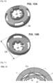
- the skirt is generally circular of revolution at rest and is ovalized under stress once assembled within the inner bearing; whereby the oval and/or elliptical deformation allows for the creation of braking torque while minimizing wear of the skirt over the life cycle.
- the skirt may have outwardly radial projections that extend beyond the general shape of revolution, the radial projections causing, once the skirt is inserted into the bearing, an ovalization of the skirt.
- the bearing may be smooth and cylindrical without interruption, projections or recesses.
- the inner bearing may be provided with a plurality of radially projecting inner radial projections projecting radially inward; thus the skirt, generally circular of revolution at rest, is ovalized under stress once assembled inside the inner bearing by the radially projecting inner projections.
- these radial projections contribute to creating a deformation stress in the skirt of the friction ring, the elastic deformation creating the desired contact zone(s).
- the skirt carries and rubs especially against internal radial projections.
- the inner bearing may comprise one or more cylindrical bearing portions of revolution and the inner radial projections project radially inwardly relative to these cylindrical portions.
- the radial projections form beads from a generally cylindrical shape. The geometry of the elliptical deformation of the skirt can thus be well controlled.
- the skirt may additionally bear and rub at some locations against the cylindrical portions of the inner bearing of the actuator housing. Consequently, contact and friction of the skirt occurs not only on the inner radial projections but also on the cylindrical portions; thereby increasing the contact area.
- a first group of internal radial projections and a second group of internal radial projections may be provided, the two groups being diametrically opposed; the ovalization effect is thus well controlled.
- the minor axis of the ellipse is imposed by the internal radial projections and the major axis of the ellipse is orthogonal to the minor axis and the ends of the skirt on the major axis side come to rest against the cylindrical bearing portions.
- the friction ring is formed as a single molded part of elastic plastic material; the proposed solution is thus particularly advantageous from an economic point of view.
- the skirt has an outside diameter D5 at rest of at least 35 mm, and preferably at least 40 millimeters. This means that the radius is larger than in known ring configurations.
- the lever arm for creating a braking torque is larger.
- the skirt furthermore bears, on the radially inner side, on the peripheral rim of the output member.
- the skirt is sandwiched between the inner bearing of the housing and the peripheral rim. This makes it possible to increase the friction and the braking effect.
- inwardly directed ridges or ribs are provided to come into contact with the peripheral rim. This makes the support on the peripheral rim more reliable by controlling the sum of the support surfaces. This gives good control of the sandwich effect.
- the ridges or ribs are regularly distributed around the circumference.
- the ring and the skirt rotate integrally with the output member, and advantageously, the braking torque is fairly constant over the 360° of rotation of the output member.
- the actuator housing includes a housing made of plastic or light alloy and a metal cover and the inner bearing, with the inner radial projections if necessary, is made in the housing. The projections are cast. This leads to a good performance-to-cost ratio.
- the inner bearing with the inner radial projections if necessary, can be made in the metal cover. This provides good durability of the inner bearing.
- the friction ring includes a generally complementary inner shaped collar with a toothing of the output gear. This allows for robust rotational drive of the friction ring, preferably without play.
- the neck serves to center the output member on the axis by cooperation with an axial bore (18) of the cover. This ensures the centering of the output member on the axis A1 defined by the bore of the cover.
- the neck comprises internal recesses for receiving the teeth of the pinion and, on the radially outer side, a cylindrical bearing surface received in the axial bore of the cover.
- the neck is of ad-hoc shape for rotational drive and geometric centering on the axis.
- the friction ring comprises an openwork plate. This facilitates the deformation and ovalization of the skirt.
- the braking torque induced by the contact is at least equal to 3 N.m.
- the limit of perception of the play of the reducer in the event of a change in loading polarity is pushed back.
- the reducer is of the hypocycloid type with an Oldham joint. This type of reducer is compact and provides a high reduction ratio.
- the inner radial projections circumscribe a first pitch circle C1
- the skirt at rest is circumscribed in a second pitch circle C2, the diameter of C2 being greater than the diameter of C1.
- the skirt comprises a succession of segments substantially forming cords, said adjacent segments two by two being connected to each other by bent junctions, the top of the bent junctions being in contact with the inner bearing.
- the skirt in cross-section to the axis, generally has a polygonal shape.
- the skirt comprises waves or undulations, which at rest have a radial dimension greater than a radial interval (E1) between the peripheral rim and the inner bearing, said waves or corrugations being compressed in the radial direction once the skirt is inserted between the peripheral rim and the inner bearing. This provides contact with radial preload having the desired friction braking effect.
- the invention also relates to a vehicle seat comprising one or more motorized drive devices as described above.
- FIG. 1 schematically represents a vehicle seat 100 comprising a seat 107 with a seat frame 101, a backrest 102 mounted on the seat, a headrest 103, the whole being mounted on a base with longitudinal slides 106, connected to the floor P of the vehicle.
- the seat may be equipped with one or more articulation mechanisms to conform to the occupant's morphology and preferences.
- This or these articulation mechanisms may include in particular a seat raising mechanism 107.
- the seat raising kinematics are known per se, and therefore not described in detail here.
- the reader can refer to the document FR2991926 .
- the lifting kinematics can use one or more connecting rods connecting the base to the seat frame.
- the lifting can be global or the lifting can be selective, namely the anterior lifting movement independent of the posterior lifting movement.
- At least one of the connecting rods may comprise a toothed sector which is in mechanical engagement with a motorized drive device 104 which is the main object of the present disclosure.
- a seat can contain a single motorized drive device 104 of the type described below, but the seat can contain two motorized drive devices, or even more than two.
- the motorized drive device 104 comprises a motor 13, an actuator housing 10, with a casing 11 and a cover 12, and an output member 3.
- the actuator housing 10 comprises a reducer which will be described later, the actuator housing is also called a reducer housing.
- the housing 11 is shaped like a bell.
- the housing 11 is formed of plastic. ABS, polypropylene, polyethylene, polyamide, etc. can be used as plastic.
- the housing could also be formed of aluminum alloy, magnesium or any light metal alloy.
- the actuator housing includes an internal bearing 1 , the purpose of which will be explained later.
- the motor 13 extends along the axis A2 and comprises a rotor which carries at its end a helical-toothed screw centered on the axis A2.
- the helical-toothed screw is engaged on an input wheel of the reducer 81.
- the reducer 8 is described more in detail below.
- the cover 12 closes the plastic casing 11.
- the cover 12 is shaped like a metal flange. The cover allows a solid and robust attachment of the motorized drive device to a seat frame element (embedded on the seat or not).
- the output member 3 comprises a toothed pinion 30. This toothing comes into constrained engagement in a toothed sector located opposite one of the connecting rods, as for example described in the document FR2991926 .
- the output member 3 comprises a peripheral rim 2.
- the peripheral rim 2 has a diameter D2.
- an axle shaft marked 31 is provided, centered on the axis A1 and on which the output pinion 3 turns.
- the output member 3 comprises a radially internal toothing 36, and the peripheral rim 2 comprises a generally cylindrical external surface arranged at least partly at the same axial position as the radially internal toothing.
- the inner bearing 1 may comprise one or more cylindrical portions 1b coinciding with a diameter D1 and the pitch circle C1. These cylindrical portions may be two in number, diametrically opposed.
- the bearing forms a continuous cylinder, for example over an angular range of 360°, or discontinuous over disjoint angular sectors.
- the contact prestress results from the force insertion with elastic deformation of the skirt with resting diameter D5 (circle C2) which is inserted into the resting diameter D1 (circle C1).
- the outside diameter D5 of the skirt 5, at rest, is at least 35 mm.
- a value close to 40 mm or greater than 40 millimeters is chosen for D5.
- D5 can also be chosen close to 45 mm.
- interruptions are expected, in particular for reasons of demolding the plastic part.
- the inner bearing 1 is provided with a plurality of inner radial projections 1a projecting radially inwards, from the inner bearing.
- the inner radial projections are called bosses or beads.
- the inner bearing can be defined with reference to a cylinder of diameter D1.
- the inner radial projections protrude radially inwards by a protrusion of a distance D7 which can range from 0.1 mm to a few tenths of a millimeter or even up to 3 mm.
- a first group G1 of internal radial projections and a second group G2 of internal radial projections are provided, the two groups G1, G2 being diametrically opposed.
- the motorized drive device 104 comprises a friction ring 4.
- the following paragraphs relate generally to the friction ring and apply, unless otherwise stated, to all embodiments and all variants.
- the friction ring 4 is formed as a single molded part of elastic plastic material.
- a polyamide, a polypropylene, a polyoxymethylene with high creep resistance may preferably be chosen. Any other plastic material resistant to creep and abrasion could also be suitable.
- the friction ring 4 comprises a neck 51, a plate 52 and a skirt 5.
- the skirt 5 of the interface ring is interposed, in a radial direction R1, between the inner bearing 1 and the peripheral rim 2 of the output member, as can be seen in Figures 5 to 9 , 11 , 14 .
- the plate 52 extends perpendicular to the axis A1.
- the plate 52 is interposed between the neck 51 and the skirt 5.
- one or more recesses 53 may be provided to facilitate the deformation and ovalization of the skirt.
- the friction ring 4 is mounted around the output member 3, and it is rotationally integral with the output member.
- the neck 51 comprises, towards the inside, hollow zones 44 and bumps 45 forming a profile complementary to the teeth 30 of the output pinion 3.
- the neck 51 comprises, towards the outside, a smooth cylindrical bearing surface 50 , of diameter D4. The neck 51 is received in the axial bore 18 of the cover.
- the skirt 5 comes into contact at least against the inner bearing 1.
- This generates a friction brake effect between the output member forming a rotating part and the inner bearing 1 forming a fixed part.
- this friction exists whatever the angular position of the output member relative to the reducer housing; in other words, there is a continuous friction effect, so that relatively constant over one revolution of the output organ 3.
- the skirt rubs against the internal radial projections 1a when the internal bearing is equipped with them.
- Four openings 53 are provided.
- skirt is generally circular in revolution at rest. It has an external diameter at rest noted D5, represented by the circle C2 on the figure 5 .
- bearing 1 When bearing 1 is provided with internal radial projections, after assembly, as is visible in the figure 8 , the friction skirt is ovalized under stress inside the inner bearing by the inner radial projections 1a.
- the minor axis of the ellipse is constrained by the distance available between the diametrically opposite projections and concerning the major axis of the ellipse, the friction of the skirt occurs directly on the cylindrical portions 1b of the inner bearing.
- the total contact surface can be quite large, in angular range this can represent a few tens of degrees.
- the output pinion 30 has a diameter D3 smaller than that D2 of the peripheral rim 2.
- the diameter of the pitch circle of the bearing is marked D1.
- D1 is at least 35 mm, preferably at least 40 mm.
- D1 D2 + E1, where E1 takes a value between 1 mm and 4 mm, as visible in the figure 8 .
- the skirt 5 at rest has a cylindrical wall of revolution without ribs directed inwards or outwards.
- the inner radial projections circumscribe a first primitive circle C1.
- the skirt at rest is circumscribed in a second primitive circle C2.
- the diameter of C2 is greater than the diameter of C1.
- C2 is between C1 and 1.10 x C1.
- the skirt has a generally polygonal shape according to a cross-section to the axis. Along the circumference of the skirt, there are substantially rectilinear segments 56 forming a cord, and rounded junctions and elbows 57.
- the polygonal shape can be decagonal, dodecagonal, or contain even more segments.
- the contact against the inner bearing of the housing occurs in the area of the vertices 57a of the joining portions. It can further be provided according to the geometry that the cord-forming segments also contact the peripheral rim in an area 58 halfway between the vertices 57a.
- chord 56 can have a reverse curvature relative to the axis.
- the skirt 5 comprises waves or undulations, which at rest have a radial dimension greater than the radial interval E1 between the peripheral rim and the inner bearing.
- the inner bearing 1 can here be cylindrical and smooth, ie without the inner radial projections discussed above.
- This ring is provided with a plurality of internal walls 54 extending parallel to the axis A1.
- the walls 54 are regularly distributed around the circumference.
- the walls 54 are also called indifferently tars or ribs. Thanks to these walls, the interposition of the skirt between the peripheral rim 2 and the internal bearing of the housing 1 is done with a radial constraint which contributes to providing a homogeneous contact all around the circumference and thus controlling the desired friction brake effect.
- the inner bearing 1 is not formed in the plastic casing, but is formed in the cover 12 by means of a circular wall or 'soyage' marked 120.
- the principle of friction of the skirt on the inner bearing is similar or identical to what was discussed above. It can There may also be bosses on the inner bearing formed in the cover to achieve the ovalizing effect described above.
- the input wheel 81 drives, directly or indirectly, an eccentric portion 82 received in an axial bore of an orbital pinion 83.
- Said orbital pinion 83 under the effect of the rotation of its eccentric portion, sees its axis A3 describe an orbital movement of a radius equivalent to the eccentricity of the eccentric portion (cf. Fig 8 ).
- the orbital pinion comprises an external circular peripheral toothed zone which is permanently engaged, for part of the toothing, in the internal radial toothing 36 of the output member 3 already mentioned and located radially outside the orbital pinion 83.
- the orbital pinion 83 comprises projecting pins 89 in the axial direction and received in grooves 88 of a guide part called a slide 84 which is detailed below.
- the slide 84 is arranged to be able to move only in translation without rotational movement about the axis A1 ; consequently, the orbital pinion 83 undergoes a movement about the axis A1 without rotating about the axis A1. Furthermore, as illustrated in figure 8 , the number of external teeth of the orbital pinion 83 is less than the number of teeth of the internal radial toothing 36 of the output member 3, the orbital movement of the orbital pinion 83 imparts a rotation to the output member 3. In the illustrated example where the difference between the number of teeth between the two toothed sectors is 1 tooth, each time the eccentric portion 82 rotates one revolution, then the internal radial toothing 36 of the output member shifts by one tooth in rotation around the axis A1.
- the orbital pinion comprises thirty-five teeth while the internal radial toothing 36 comprises thirty-six teeth, which gives a reduction ratio of 35 for the reducer 8.
- the slide 84 comprises four arms 87 which extend in a plane perpendicular to the axis A1 and which are received in grooves 187 formed in the plastic casing 11 to allow a translational movement in the direction W perpendicular to the axis A1 and to prevent any rotation of the slide 84 about the axis A1.
- the slide comprises the grooves 88 extending along the direction V perpendicular to the direction W and to the axial direction A, the two diametrically opposed protruding pins 89 having just engaged in the grooves 88.
- the orbital pinion 83 can translate in a direction V inside the slide, but without rotation about A1; the slide 84 can translate relative to the axis W in the base but again without rotation about A1.
- This assembly is also known as an ⁇ oldham' joint. Indeed, these two translations make it possible to compensate for the orbital movement created by the eccentric portion so that the movement of the output member 3 is exactly coaxial with the input rotation movement of the input wheel 81.
- the slide 84 is received in a base formed in the plastic casing 11.
- the slide is made of metal, it is generally secured inside the casing 11 by means of four tenons 17 which are inserted between the arms 87 of the slide.
- the fixing screws 19 come to frame the arms of the Slider from the outside.
- the fixing screws 19 make it possible to assemble the cover 12 on the plastic casing 11 and thus form the closed actuator housing 10.
- the motorized drive device could be used to motorize a seat adjustment movement other than the seat riser.
- the inner bearing may have a discontinuous and/or protruding surface opposite a smooth skirt surface, as illustrated in FIG. figure13 .
- the inner bearing may have a continuous surface with respect to a skirt surface with radial projections as illustrated in FIG. figure 14 .
Landscapes
- Engineering & Computer Science (AREA)
- Aviation & Aerospace Engineering (AREA)
- Transportation (AREA)
- Mechanical Engineering (AREA)
- Chairs For Special Purposes, Such As Reclining Chairs (AREA)
- Retarders (AREA)
- Seats For Vehicles (AREA)
Claims (17)
- Motorisierte Antriebsvorrichtung für einen Fahrzeugsitz mit einem Sitzrahmen, wobei die Antriebsvorrichtung dazu bestimmt ist, die Verschiebung eines beweglichen Elements anzutreiben, das mit dem Sitzrahmen verbunden ist, insbesondere für eine Sitzerhöhungsbewegung, wobei die Vorrichtung umfasst:- einen Aktuator (13) und ein Aktuatorgehäuse (10), das mindestens ein Untersetzungsgetriebe (8) enthält,- ein Abtriebselement (3), das um eine Achse (A1) drehbar gelagert ist, wobei das Abtriebselement einen Umfangskranz (2) umfasst,- einen Reibring (4), der um das Abtriebselement herum montiert und drehfest mit dem Abtriebselement verbunden ist, dadurch gekennzeichnet, dass der Reibring eine Schürze (5) umfasst,- wobei das Aktuatorgehäuse ein Innenlager (1) zum Aufnehmen der Schürze umfasst und- wobei die Schürze mit mindestens dem Innenlager in Kontakt ist, um eine Reibungsbremse zwischen dem Abtriebselement, das ein rotierendes Stück bildet, und dem Innenlager, das ein feststehendes Stück bildet, zu bilden.
- Antriebsvorrichtung nach Anspruch 1, wobei die Schürze im Ruhezustand im Allgemeinen drehkreisförmig ist und unter Spannung unrund gemacht wird, sobald sie im Inneren des Innenlagers zusammengebaut ist.
- Antriebsvorrichtung nach einem der Ansprüche 1 bis 2, wobei das Innenlager mit einer Vielzahl von radial nach innen vorstehenden inneren radialen Vorsprüngen (1a) versehen ist.
- Antriebsvorrichtung nach Anspruch 3, wobei eine erste Gruppe (G1) von inneren radialen Vorsprüngen und eine zweite Gruppe (G2) von inneren radialen Vorsprüngen vorgesehen sind, wobei die beiden Gruppen einander diametral gegenüberliegen.
- Antriebsvorrichtung nach einem der Ansprüche 1 bis 4, wobei der Reibring (4) als ein einstückiges Formteil aus elastischem Kunststoffmaterial ausgebildet ist.
- Antriebsvorrichtung nach einem der Ansprüche 1 bis 5, wobei die Schürze einen Außendurchmesser (D5) im Ruhezustand von mindestens 35 mm, bevorzugt mindestens 40 Millimeter, aufweist.
- Antriebsvorrichtung nach einem der Ansprüche 1 bis 6, wobei sich die Schürze zusätzlich auf der radial inneren Seite auf dem Umfangskranz des Abtriebselements abstützt
- Antriebsvorrichtung nach Anspruch 7, wobei nach innen gerichtete Ansätze/Rippen (54) vorgesehen sind, um mit dem Kranz in Kontakt zu kommen.
- Antriebsvorrichtung nach einem der Ansprüche 1 bis 8, wobei das Aktuatorgehäuse ein Gehäuse (11) aus Kunststoff oder aus einer Leichtmetalllegierung und einen Metalldeckel (12) umfasst und das Innenlager, gegebenenfalls mit den inneren radialen Vorsprüngen, in dem Gehäuse ausgeführt sind.
- Antriebsvorrichtung nach einem der Ansprüche 1 bis 8, wobei das Aktuatorgehäuse ein Gehäuse (11) aus Kunststoff oder aus einer Leichtmetalllegierung und einen Metalldeckel (12) umfasst und das Innenlager, gegebenenfalls mit den inneren radialen Vorsprüngen, in dem Metalldeckel ausgeführt sein kann.
- Antriebsvorrichtung nach einem der Ansprüche 1 bis 10, wobei der Reibring einen Innenformkragen (51) umfasst, die im Allgemeinen komplementär zu einer Zahnung (30) des Abtriebsritzels ist.
- Antriebsvorrichtung nach einem der Ansprüche 1 bis 11, wobei der Reibring eine durchbrochene Platte (52) umfasst.
- Antriebsvorrichtung nach einem der Ansprüche 1 bis 12, wobei das Untersetzungsgetriebe ein hypozykloides Oldham-Gelenk ist.
- Antriebsvorrichtung nach einem der Ansprüche 1 bis 12, wobei die inneren radialen Vorsprünge einen ersten Wälzkreis (C1) eingrenzen und die Schürze im Ruhezustand in einem zweiten Wälzkreis (C2) eingegrenzt ist, wobei der Durchmesser von (C2) größer als der Durchmesser von (C1) ist.
- Antriebsvorrichtung nach einem der Ansprüche 1 bis 14, wobei die Schürze eine Folge von Segmenten (56) umfasst, die im Wesentlichen Schnüre bilden, wobei die paarweise aneinandergrenzenden Segmente durch abgewinkelte Verbindungen (57) miteinander verbunden sind, wobei die Spitze (57a) der abgewinkelten Verbindungen in Kontakt mit dem Innenlager (1) ist.
- Antriebsvorrichtung nach einem der Ansprüche 1 bis 14, wobei die Schürze (5) Wellen oder Riffel umfasst, die im Ruhezustand eine radiale Abmessung aufweisen, die größer als ein radiales Intervall (E1) zwischen dem Umfangskranz (2) und dem Innenlager (1) ist, wobei die Wellen oder die Riffel in radialer Richtung zusammengedrückt werden, sobald die Schürze zwischen dem Umfangskranz (2) und dem Innenlager (1) eingeführt ist.
- Sitz für ein Kraftfahrzeug, umfassend eine Antriebsvorrichtung nach einem der Ansprüche 1 bis 16.
Applications Claiming Priority (1)
| Application Number | Priority Date | Filing Date | Title |
|---|---|---|---|
| FR2203990A FR3135026B1 (fr) | 2022-04-28 | 2022-04-28 | Dispositif d'entrainement motorise pour rehausse de siege de vehicule |
Publications (2)
| Publication Number | Publication Date |
|---|---|
| EP4272998A1 EP4272998A1 (de) | 2023-11-08 |
| EP4272998B1 true EP4272998B1 (de) | 2025-02-12 |
Family
ID=82483077
Family Applications (1)
| Application Number | Title | Priority Date | Filing Date |
|---|---|---|---|
| EP23167817.8A Active EP4272998B1 (de) | 2022-04-28 | 2023-04-13 | Motorischer antrieb für einen höhenverstellbaren fahrzeugsitz |
Country Status (4)
| Country | Link |
|---|---|
| US (1) | US12552293B2 (de) |
| EP (1) | EP4272998B1 (de) |
| CN (1) | CN116968600A (de) |
| FR (1) | FR3135026B1 (de) |
Family Cites Families (5)
| Publication number | Priority date | Publication date | Assignee | Title |
|---|---|---|---|---|
| FR2991926B1 (fr) | 2012-06-19 | 2015-08-21 | Faurecia Sieges Automobile | Dispositif d'entrainement motorise pour siege de vehicule |
| US20180216717A1 (en) * | 2017-01-31 | 2018-08-02 | Brose Fahrzeugteile Gmbh & Co. Kommanditgesellschaft, Coburg | Electromotive ancillary unit |
| DE202017106652U1 (de) * | 2017-11-03 | 2017-11-13 | Faurecia Autositze Gmbh | Zweistufiges Getriebe für einen Verstellantrieb sowie Verstellantrieb für einen Kraftfahrzeugsitz |
| FR3086597B1 (fr) * | 2018-10-02 | 2020-10-23 | Faurecia Sieges Dautomobile | Mecanisme de reglage pour siege de vehicule, siege de vehicule comprenant un tel mecanisme |
| US10830310B2 (en) * | 2019-02-28 | 2020-11-10 | Lear Corporation | Gear assembly |
-
2022
- 2022-04-28 FR FR2203990A patent/FR3135026B1/fr active Active
-
2023
- 2023-04-13 EP EP23167817.8A patent/EP4272998B1/de active Active
- 2023-04-19 CN CN202310424191.3A patent/CN116968600A/zh active Pending
- 2023-04-26 US US18/307,460 patent/US12552293B2/en active Active
Also Published As
| Publication number | Publication date |
|---|---|
| CN116968600A (zh) | 2023-10-31 |
| US12552293B2 (en) | 2026-02-17 |
| FR3135026A1 (fr) | 2023-11-03 |
| FR3135026B1 (fr) | 2024-05-03 |
| EP4272998A1 (de) | 2023-11-08 |
| US20230347793A1 (en) | 2023-11-02 |
Similar Documents
| Publication | Publication Date | Title |
|---|---|---|
| FR2998837A1 (fr) | Ensemble d'articulation pour siege de vehicule | |
| FR2977205A1 (fr) | Dispositif de reglage angulaire pour siege de vehicule | |
| FR2967102A1 (fr) | Mecanisme de reglage pour siege de vehicule | |
| FR2883812A1 (fr) | Mecanisme d'articulation, son procede de fabrication et siege de vehicule comportant un tel mecanisme | |
| EP0770514A1 (de) | Gelenkbeschlag für Fahrzeugsitze | |
| FR3018051A1 (fr) | Mecanisme d'articulation et siege de vehicule comportant un tel mecanisme | |
| CH699988A2 (fr) | Organe moteur pour mouvement horloger. | |
| WO2013011218A1 (fr) | Dispositif d'entrainement a moteur electrique et reducteur | |
| FR3024080A1 (fr) | Dispositif de reglage angulaire pour siege de vehicule | |
| FR2875872A1 (fr) | Entrainement | |
| FR2781437A1 (fr) | Articulation destinee notamment a un siege de vehicule automobile | |
| FR2915436A1 (fr) | Mecanisme d'articulation et siege de vehicule comportant un tel mecanisme. | |
| EP0685374A1 (de) | Getriebemotor, insbesondere für eine Fahrzeugscheibenwischeranlage | |
| EP3253615A1 (de) | Lösbare scharnieranordnung für einen kraftfahrzeugsitz | |
| FR2991926A1 (fr) | Dispositif d'entrainement motorise pour siege de vehicule | |
| WO2010109127A1 (fr) | Mecanisme de reglage irreversible pour siege de vehicule | |
| EP4272998A1 (de) | Motorischer antrieb für einen höhenverstellbaren fahrzeugsitz | |
| FR2789142A1 (fr) | Mecanisme de reglage, et ensemble d'assise comportant un tel mecanisme | |
| FR2770810A1 (fr) | Mecanisme d'articulation pour siege de vehicule, et siege de vehicule comportant un tel mecanisme | |
| FR3073460A1 (fr) | Mecanisme d'articulation et siege de vehicule comportant un tel mecanisme | |
| FR3011513A1 (fr) | Ensemble d'articulation debrayable pour siege de vehicule automobile. | |
| FR2741661A1 (fr) | Dispositif d'entrainement en rotation d'un element d'enroulement de volet roulant | |
| FR2690887A1 (fr) | Rétroviseur pour un véhicule équipé d'un type perfectionné de dispositif de support et d'orientation pour une plaque réfléchissante. | |
| EP0711689B1 (de) | Getriebemotor mit einem hohlen, mit einem Verschlussdeckel versehenen Gehäuse, insbesondere für Kraftfahrzeug-Scheibenmischeranlage | |
| EP2978629B1 (de) | Entkuppelbare gelenkanordnung für einen kraftfahrzeugsitz |
Legal Events
| Date | Code | Title | Description |
|---|---|---|---|
| PUAI | Public reference made under article 153(3) epc to a published international application that has entered the european phase |
Free format text: ORIGINAL CODE: 0009012 |
|
| STAA | Information on the status of an ep patent application or granted ep patent |
Free format text: STATUS: THE APPLICATION HAS BEEN PUBLISHED |
|
| AK | Designated contracting states |
Kind code of ref document: A1 Designated state(s): AL AT BE BG CH CY CZ DE DK EE ES FI FR GB GR HR HU IE IS IT LI LT LU LV MC ME MK MT NL NO PL PT RO RS SE SI SK SM TR |
|
| STAA | Information on the status of an ep patent application or granted ep patent |
Free format text: STATUS: REQUEST FOR EXAMINATION WAS MADE |
|
| 17P | Request for examination filed |
Effective date: 20240424 |
|
| RBV | Designated contracting states (corrected) |
Designated state(s): AL AT BE BG CH CY CZ DE DK EE ES FI FR GB GR HR HU IE IS IT LI LT LU LV MC ME MK MT NL NO PL PT RO RS SE SI SK SM TR |
|
| GRAP | Despatch of communication of intention to grant a patent |
Free format text: ORIGINAL CODE: EPIDOSNIGR1 |
|
| STAA | Information on the status of an ep patent application or granted ep patent |
Free format text: STATUS: GRANT OF PATENT IS INTENDED |
|
| INTG | Intention to grant announced |
Effective date: 20240927 |
|
| RIN1 | Information on inventor provided before grant (corrected) |
Inventor name: LIANG, NILES Inventor name: NAVATTE, NICOLAS Inventor name: RDZANEK, EMIL |
|
| GRAS | Grant fee paid |
Free format text: ORIGINAL CODE: EPIDOSNIGR3 |
|
| GRAA | (expected) grant |
Free format text: ORIGINAL CODE: 0009210 |
|
| STAA | Information on the status of an ep patent application or granted ep patent |
Free format text: STATUS: THE PATENT HAS BEEN GRANTED |
|
| AK | Designated contracting states |
Kind code of ref document: B1 Designated state(s): AL AT BE BG CH CY CZ DE DK EE ES FI FR GB GR HR HU IE IS IT LI LT LU LV MC ME MK MT NL NO PL PT RO RS SE SI SK SM TR |
|
| REG | Reference to a national code |
Ref country code: GB Ref legal event code: FG4D Free format text: NOT ENGLISH |
|
| REG | Reference to a national code |
Ref country code: CH Ref legal event code: EP |
|
| REG | Reference to a national code |
Ref country code: DE Ref legal event code: R096 Ref document number: 602023001969 Country of ref document: DE |
|
| REG | Reference to a national code |
Ref country code: IE Ref legal event code: FG4D Free format text: LANGUAGE OF EP DOCUMENT: FRENCH |
|
| REG | Reference to a national code |
Ref country code: NL Ref legal event code: MP Effective date: 20250212 |
|
| PG25 | Lapsed in a contracting state [announced via postgrant information from national office to epo] |
Ref country code: RS Free format text: LAPSE BECAUSE OF FAILURE TO SUBMIT A TRANSLATION OF THE DESCRIPTION OR TO PAY THE FEE WITHIN THE PRESCRIBED TIME-LIMIT Effective date: 20250512 |
|
| PG25 | Lapsed in a contracting state [announced via postgrant information from national office to epo] |
Ref country code: FI Free format text: LAPSE BECAUSE OF FAILURE TO SUBMIT A TRANSLATION OF THE DESCRIPTION OR TO PAY THE FEE WITHIN THE PRESCRIBED TIME-LIMIT Effective date: 20250212 |
|
| PG25 | Lapsed in a contracting state [announced via postgrant information from national office to epo] |
Ref country code: PL Free format text: LAPSE BECAUSE OF FAILURE TO SUBMIT A TRANSLATION OF THE DESCRIPTION OR TO PAY THE FEE WITHIN THE PRESCRIBED TIME-LIMIT Effective date: 20250212 |
|
| PGFP | Annual fee paid to national office [announced via postgrant information from national office to epo] |
Ref country code: DE Payment date: 20250319 Year of fee payment: 3 |
|
| PG25 | Lapsed in a contracting state [announced via postgrant information from national office to epo] |
Ref country code: ES Free format text: LAPSE BECAUSE OF FAILURE TO SUBMIT A TRANSLATION OF THE DESCRIPTION OR TO PAY THE FEE WITHIN THE PRESCRIBED TIME-LIMIT Effective date: 20250212 |
|
| REG | Reference to a national code |
Ref country code: LT Ref legal event code: MG9D |
|
| PG25 | Lapsed in a contracting state [announced via postgrant information from national office to epo] |
Ref country code: IS Free format text: LAPSE BECAUSE OF FAILURE TO SUBMIT A TRANSLATION OF THE DESCRIPTION OR TO PAY THE FEE WITHIN THE PRESCRIBED TIME-LIMIT Effective date: 20250612 Ref country code: NO Free format text: LAPSE BECAUSE OF FAILURE TO SUBMIT A TRANSLATION OF THE DESCRIPTION OR TO PAY THE FEE WITHIN THE PRESCRIBED TIME-LIMIT Effective date: 20250512 |
|
| PG25 | Lapsed in a contracting state [announced via postgrant information from national office to epo] |
Ref country code: NL Free format text: LAPSE BECAUSE OF FAILURE TO SUBMIT A TRANSLATION OF THE DESCRIPTION OR TO PAY THE FEE WITHIN THE PRESCRIBED TIME-LIMIT Effective date: 20250212 |
|
| PG25 | Lapsed in a contracting state [announced via postgrant information from national office to epo] |
Ref country code: HR Free format text: LAPSE BECAUSE OF FAILURE TO SUBMIT A TRANSLATION OF THE DESCRIPTION OR TO PAY THE FEE WITHIN THE PRESCRIBED TIME-LIMIT Effective date: 20250212 |
|
| PG25 | Lapsed in a contracting state [announced via postgrant information from national office to epo] |
Ref country code: PT Free format text: LAPSE BECAUSE OF FAILURE TO SUBMIT A TRANSLATION OF THE DESCRIPTION OR TO PAY THE FEE WITHIN THE PRESCRIBED TIME-LIMIT Effective date: 20250612 Ref country code: LV Free format text: LAPSE BECAUSE OF FAILURE TO SUBMIT A TRANSLATION OF THE DESCRIPTION OR TO PAY THE FEE WITHIN THE PRESCRIBED TIME-LIMIT Effective date: 20250212 |
|
| PG25 | Lapsed in a contracting state [announced via postgrant information from national office to epo] |
Ref country code: BG Free format text: LAPSE BECAUSE OF FAILURE TO SUBMIT A TRANSLATION OF THE DESCRIPTION OR TO PAY THE FEE WITHIN THE PRESCRIBED TIME-LIMIT Effective date: 20250212 Ref country code: GR Free format text: LAPSE BECAUSE OF FAILURE TO SUBMIT A TRANSLATION OF THE DESCRIPTION OR TO PAY THE FEE WITHIN THE PRESCRIBED TIME-LIMIT Effective date: 20250513 |
|
| REG | Reference to a national code |
Ref country code: AT Ref legal event code: MK05 Ref document number: 1765790 Country of ref document: AT Kind code of ref document: T Effective date: 20250212 |
|
| PG25 | Lapsed in a contracting state [announced via postgrant information from national office to epo] |
Ref country code: SE Free format text: LAPSE BECAUSE OF FAILURE TO SUBMIT A TRANSLATION OF THE DESCRIPTION OR TO PAY THE FEE WITHIN THE PRESCRIBED TIME-LIMIT Effective date: 20250212 |
|
| PG25 | Lapsed in a contracting state [announced via postgrant information from national office to epo] |
Ref country code: SM Free format text: LAPSE BECAUSE OF FAILURE TO SUBMIT A TRANSLATION OF THE DESCRIPTION OR TO PAY THE FEE WITHIN THE PRESCRIBED TIME-LIMIT Effective date: 20250212 |
|
| PG25 | Lapsed in a contracting state [announced via postgrant information from national office to epo] |
Ref country code: DK Free format text: LAPSE BECAUSE OF FAILURE TO SUBMIT A TRANSLATION OF THE DESCRIPTION OR TO PAY THE FEE WITHIN THE PRESCRIBED TIME-LIMIT Effective date: 20250212 |
|
| PG25 | Lapsed in a contracting state [announced via postgrant information from national office to epo] |
Ref country code: IT Free format text: LAPSE BECAUSE OF FAILURE TO SUBMIT A TRANSLATION OF THE DESCRIPTION OR TO PAY THE FEE WITHIN THE PRESCRIBED TIME-LIMIT Effective date: 20250212 |
|
| PG25 | Lapsed in a contracting state [announced via postgrant information from national office to epo] |
Ref country code: AT Free format text: LAPSE BECAUSE OF FAILURE TO SUBMIT A TRANSLATION OF THE DESCRIPTION OR TO PAY THE FEE WITHIN THE PRESCRIBED TIME-LIMIT Effective date: 20250212 |
|
| PG25 | Lapsed in a contracting state [announced via postgrant information from national office to epo] |
Ref country code: EE Free format text: LAPSE BECAUSE OF FAILURE TO SUBMIT A TRANSLATION OF THE DESCRIPTION OR TO PAY THE FEE WITHIN THE PRESCRIBED TIME-LIMIT Effective date: 20250212 Ref country code: CZ Free format text: LAPSE BECAUSE OF FAILURE TO SUBMIT A TRANSLATION OF THE DESCRIPTION OR TO PAY THE FEE WITHIN THE PRESCRIBED TIME-LIMIT Effective date: 20250212 |
|
| PG25 | Lapsed in a contracting state [announced via postgrant information from national office to epo] |
Ref country code: RO Free format text: LAPSE BECAUSE OF FAILURE TO SUBMIT A TRANSLATION OF THE DESCRIPTION OR TO PAY THE FEE WITHIN THE PRESCRIBED TIME-LIMIT Effective date: 20250212 |
|
| PG25 | Lapsed in a contracting state [announced via postgrant information from national office to epo] |
Ref country code: SK Free format text: LAPSE BECAUSE OF FAILURE TO SUBMIT A TRANSLATION OF THE DESCRIPTION OR TO PAY THE FEE WITHIN THE PRESCRIBED TIME-LIMIT Effective date: 20250212 |
|
| REG | Reference to a national code |
Ref country code: DE Ref legal event code: R097 Ref document number: 602023001969 Country of ref document: DE |
|
| PG25 | Lapsed in a contracting state [announced via postgrant information from national office to epo] |
Ref country code: LU Free format text: LAPSE BECAUSE OF NON-PAYMENT OF DUE FEES Effective date: 20250413 |
|
| PLBE | No opposition filed within time limit |
Free format text: ORIGINAL CODE: 0009261 |
|
| STAA | Information on the status of an ep patent application or granted ep patent |
Free format text: STATUS: NO OPPOSITION FILED WITHIN TIME LIMIT |
|
| PG25 | Lapsed in a contracting state [announced via postgrant information from national office to epo] |
Ref country code: MC Free format text: LAPSE BECAUSE OF FAILURE TO SUBMIT A TRANSLATION OF THE DESCRIPTION OR TO PAY THE FEE WITHIN THE PRESCRIBED TIME-LIMIT Effective date: 20250212 |
|
| REG | Reference to a national code |
Ref country code: BE Ref legal event code: MM Effective date: 20250430 |
|
| PG25 | Lapsed in a contracting state [announced via postgrant information from national office to epo] |
Ref country code: BE Free format text: LAPSE BECAUSE OF NON-PAYMENT OF DUE FEES Effective date: 20250430 |
|
| 26N | No opposition filed |
Effective date: 20251113 |
|
| PG25 | Lapsed in a contracting state [announced via postgrant information from national office to epo] |
Ref country code: IE Free format text: LAPSE BECAUSE OF NON-PAYMENT OF DUE FEES Effective date: 20250413 |
|
| PGFP | Annual fee paid to national office [announced via postgrant information from national office to epo] |
Ref country code: FR Payment date: 20260320 Year of fee payment: 4 |