EP4272583B1 - Snap-seal particulate aerosol-generating article - Google Patents
Snap-seal particulate aerosol-generating article Download PDFInfo
- Publication number
- EP4272583B1 EP4272583B1 EP22862400.3A EP22862400A EP4272583B1 EP 4272583 B1 EP4272583 B1 EP 4272583B1 EP 22862400 A EP22862400 A EP 22862400A EP 4272583 B1 EP4272583 B1 EP 4272583B1
- Authority
- EP
- European Patent Office
- Prior art keywords
- component
- aerosol
- granular
- outer tube
- airflow channel
- Prior art date
- Legal status (The legal status is an assumption and is not a legal conclusion. Google has not performed a legal analysis and makes no representation as to the accuracy of the status listed.)
- Active
Links
Images


Classifications
-
- A—HUMAN NECESSITIES
- A24—TOBACCO; CIGARS; CIGARETTES; SIMULATED SMOKING DEVICES; SMOKERS' REQUISITES
- A24D—CIGARS; CIGARETTES; TOBACCO SMOKE FILTERS; MOUTHPIECES OF CIGARS OR CIGARETTES; MANUFACTURE OF TOBACCO SMOKE FILTERS OR MOUTHPIECES
- A24D1/00—Cigars; Cigarettes
- A24D1/20—Cigarettes specially adapted for simulated smoking devices
-
- A—HUMAN NECESSITIES
- A24—TOBACCO; CIGARS; CIGARETTES; SIMULATED SMOKING DEVICES; SMOKERS' REQUISITES
- A24D—CIGARS; CIGARETTES; TOBACCO SMOKE FILTERS; MOUTHPIECES OF CIGARS OR CIGARETTES; MANUFACTURE OF TOBACCO SMOKE FILTERS OR MOUTHPIECES
- A24D1/00—Cigars; Cigarettes
- A24D1/002—Cigars; Cigarettes with additives, e.g. for flavouring
-
- A—HUMAN NECESSITIES
- A24—TOBACCO; CIGARS; CIGARETTES; SIMULATED SMOKING DEVICES; SMOKERS' REQUISITES
- A24D—CIGARS; CIGARETTES; TOBACCO SMOKE FILTERS; MOUTHPIECES OF CIGARS OR CIGARETTES; MANUFACTURE OF TOBACCO SMOKE FILTERS OR MOUTHPIECES
- A24D1/00—Cigars; Cigarettes
- A24D1/02—Cigars; Cigarettes with special covers
- A24D1/027—Cigars; Cigarettes with special covers with ventilating means, e.g. perforations
-
- A—HUMAN NECESSITIES
- A24—TOBACCO; CIGARS; CIGARETTES; SIMULATED SMOKING DEVICES; SMOKERS' REQUISITES
- A24D—CIGARS; CIGARETTES; TOBACCO SMOKE FILTERS; MOUTHPIECES OF CIGARS OR CIGARETTES; MANUFACTURE OF TOBACCO SMOKE FILTERS OR MOUTHPIECES
- A24D3/00—Tobacco smoke filters, e.g. filter tips or filtering inserts; Filters specially adapted for simulated smoking devices; Mouthpieces of cigars or cigarettes
- A24D3/17—Filters specially adapted for simulated smoking devices
-
- A—HUMAN NECESSITIES
- A24—TOBACCO; CIGARS; CIGARETTES; SIMULATED SMOKING DEVICES; SMOKERS' REQUISITES
- A24F—SMOKERS' REQUISITES; MATCH BOXES; SIMULATED SMOKING DEVICES
- A24F40/00—Electrically operated smoking devices; Component parts thereof; Manufacture thereof; Maintenance or testing thereof; Charging means specially adapted therefor
- A24F40/20—Devices using solid inhalable precursors
-
- A—HUMAN NECESSITIES
- A24—TOBACCO; CIGARS; CIGARETTES; SIMULATED SMOKING DEVICES; SMOKERS' REQUISITES
- A24F—SMOKERS' REQUISITES; MATCH BOXES; SIMULATED SMOKING DEVICES
- A24F40/00—Electrically operated smoking devices; Component parts thereof; Manufacture thereof; Maintenance or testing thereof; Charging means specially adapted therefor
- A24F40/40—Constructional details, e.g. connection of cartridges and battery parts
- A24F40/46—Shape or structure of electric heating means
-
- A—HUMAN NECESSITIES
- A24—TOBACCO; CIGARS; CIGARETTES; SIMULATED SMOKING DEVICES; SMOKERS' REQUISITES
- A24F—SMOKERS' REQUISITES; MATCH BOXES; SIMULATED SMOKING DEVICES
- A24F40/00—Electrically operated smoking devices; Component parts thereof; Manufacture thereof; Maintenance or testing thereof; Charging means specially adapted therefor
- A24F40/40—Constructional details, e.g. connection of cartridges and battery parts
- A24F40/46—Shape or structure of electric heating means
- A24F40/465—Shape or structure of electric heating means specially adapted for induction heating
-
- Y—GENERAL TAGGING OF NEW TECHNOLOGICAL DEVELOPMENTS; GENERAL TAGGING OF CROSS-SECTIONAL TECHNOLOGIES SPANNING OVER SEVERAL SECTIONS OF THE IPC; TECHNICAL SUBJECTS COVERED BY FORMER USPC CROSS-REFERENCE ART COLLECTIONS [XRACs] AND DIGESTS
- Y02—TECHNOLOGIES OR APPLICATIONS FOR MITIGATION OR ADAPTATION AGAINST CLIMATE CHANGE
- Y02W—CLIMATE CHANGE MITIGATION TECHNOLOGIES RELATED TO WASTEWATER TREATMENT OR WASTE MANAGEMENT
- Y02W90/00—Enabling technologies or technologies with a potential or indirect contribution to greenhouse gas [GHG] emissions mitigation
- Y02W90/10—Bio-packaging, e.g. packing containers made from renewable resources or bio-plastics
Definitions
- the present disclosure belongs to the technical field of aerosol generating product, and in particular, to an aerosol generating product by using aerosol source-material granules, and more specifically, to a sealing-type granular aerosol generating product.
- Aerosol granular generating products are a new type of Heat-Not-Burn (HNB) aerosol generating products in recent years, using aerosol source-material granules instead of aerosol source-material flakes as aerosol generating materials, as aerosol source-material granules are heated more evenly than aerosol source-material flakes, and aerosols diffuse more smoothly along the gap among granules than that among flake materials, they are deeply welcomed by consumers.
- HNB Heat-Not-Burn
- CN 109965366 A discloses a heat-not-burn cigarette.
- the cigarette includes a cylindrical package, a cigarette core element, a smoke circulation element and a filter element, wherein the cigarette core element, a smoke circulation element and a filter element are sequentially arranged inside the cylindrical package; a plurality of smoke passages are formed in the smoke circulation element; the smokecirculation element is spaced from the filter element, and the heat-not-burn cigarette further includes a first hollow part arranged between the smoke circulation element and the filter element.
- the heat-not-burn cigarette has the advantages that the smoke amount is large, and the temperature of smoke in the mouth is low.
- CN21075873 U discloses a heated non combustible cigarette, which sequentially comprises: an aerosol generation section (1), a support element (2), a cooling section (3), and a filter section (4);
- the supporting element (2) is an empty tube with a tube wall (21) and a tube lumen (22), wherein the tube wall (21) comprises an outer wrapping layer (211) and a groove corrugated layer (213), and the groove corrugated layer (213) is close to the tube lumen (22).
- the pipe wall (21) of the support element (2) described in this utility model can bounce back after being cut by a knife, and the support element (2) has high adaptability to the machine, improving the production efficiency and product quality of cigarettes.
- the support element (2) described in this utility model is not prone to collapse, and has high support performance for cigarettes.
- US 2022/0309341 discloses a feature that, during storage of a heated tobacco product having a tobacco rod formed by filling the inside of wrapping paper with a tobacco filler containing a tobacco raw material and an aerosol-source material, suppresses occlusion of a heater-insertion cavity open on the distal end surface side of the tobacco rod.
- This heated tobacco product has a tobacco rod formed by filling the inside of wrapping paper with a tobacco filler containing cut tobacco and an aerosol-source material, and is provided with: a heater-insertion cavity that is open on the distal end surface side of the tobacco rod and extends in the axial direction of the tobacco rod, and into which a heater of a heating device is inserted; and a coating layer that is formed on the lateral periphery of the heater-insertion cavity of the tobacco rod, and suppresses occlusion of the heater-insertion cavity.
- CN113662239 A according to its abstract discloses an aerosol generating product with a perfumed cigarette core section.
- the aerosol generating product comprises a fuming core material section, a supporting section, a breathable hollow section and a filtering section which are arranged in sequence.
- the supporting section has a perfuming function and is provided with a large hollow hole and a plurality of small perfuming holes; the multiple small perfuming holes surround the outer side of the large hollow hole, and perfuming capsules are arranged at the ends of the sides, close to the fuming core material section, in part of the small perfuming holes; an impermeable layer is arranged in forming paper; and ventilation holes penetrating through the ventilation hollow section in the radial direction are formed in the ventilation hollow section.
- Granular aerosol generating products are known on the market, the structure is illustrated with reference to FIG.1 : the main structure is an integrated outer sleeve X1, the distal lip is sealed by the sealing film X2, which is filled with aerosol source-material granules X3 to form a granule section, a multi-hole firmware section (commonly known as "gear") X4 is set in the downstream of the granule section, and an airflow channel section X5 is set aside for collecting and accommodating aerosol (the airflow channel section X5 is either a separate cavity or a hollow rod), the downstream of the airflow channel section X5 is a filtering section X6, which is also used as a cigarette holder for users to take in their mouths.
- the main structure is an integrated outer sleeve X1
- the distal lip is sealed by the sealing film X2
- a multi-hole firmware section (commonly known as "gear") X4 is set in the downstream of the
- the distal lip end When using aerosol generating products, the distal lip end is inserted into the heating appliance, the heating appliance has a heating element to heat aerosol source-material granules so as to release gaseous aroma components, gaseous aroma components in the airflow channel section X5 are condensed into visible aerosol by cold air, and the aerosol is filtered through the filtering section and enters users' mouths.
- the airflow channel section X5 is crucial for aerosol formation, according to scientific theories of aerosol, gaseous aroma components released by heat need to be cooled and condense into solid or liquid granules, such solid or liquid granules need to be suspended in the air to form visible aerosol (commonly known as "smoke” or “fog” or generally known as “smog”).
- visible aerosol commonly known as "smoke” or "fog” or generally known as "smog”
- the airflow channel section X5 must be left in the existing granular aerosol generating products.
- the sealing film X2 is usually a high-permeability thin paper, it is pasted to the upstream end face of the outer sleeve X1 by bonding; however, the bonding process of the sealing film X2 is complex and inefficient, requiring special bonding sealing film equipment. Besides, due to the fact that the outer sleeve X1 end face is not in the same plane, which has burrs and defects on thin paper surface as well as uneven gluing, etc., the sealing film is not reliable, thus the sealing film sealing the lips of cigarettes is degummed in subsequent production processes, resulting in leakage of internal storage granule material, which not only pollutes production environment, but causes loss of other materials and affects production efficiency.
- the multi-hole firmware section X4 is usually made of ceramic or silica gel, the outer wall is firmly bonded to the inner wall of the paper cylinder by adhesive, there is at least one axial through-hole X41 in the center and/or at least one peripheral ventilation groove X42 on the periphery, their sizes can allow smog while not allowing aerosol source-material granules to pass through; thus, blocking aerosol source-material granules and transmitting flue gas can be realized.
- the existence of multi-hole firmware section brings more costs and operational inconveniences to industrial manufacturing of granular aerosol generating products, thus, those skilled in the art have been hoping to eliminate the multi-hole firmware section.
- the airflow channel section must be set in the downstream of the granule section to gather and accommodate aerosols, and the section can also constrain scattered aerosol source-material granules, resulting in a dilemma.
- the present disclosure aims to solve the problems above.
- the present disclosure provides a sealing-type granular aerosol generating product, which includes a filtering component 1, a groove corrugated component 2, an aerosol source-material granule 3 and a sealing component 4 arranged in turn from the proximal to the distal lip end, an outer sleeve 5 is provided outside each component;
- the groove corrugated component 2 is a cylinder with a hollow cavity 22 surrounded by the first sheet of a groove corrugated structure 21, a first airflow channel 23 that axially penetrates the groove corrugated structure 21 forms between the groove corrugated structure 21 and the outer tube 5, a plugging part 24 is provided inside the hollow cavity 22.
- the shape of the groove in the groove corrugated structure 21 is selected from, but not limited to the "V” type or the "U” type.
- the upstream and downstream mentioned in the present disclosure are determined by the direction of gas flow. More specifically, the distal lip end is upstream and the proximal lip end is downstream.
- the arrangement in turn is not limited to close connection of the two, but only limitation of the order. That is to say, other forms of units can be inserted between any of the filtering component 1, the groove corrugated component 2, the aerosol source-material granule 3 and the sealing component 4.
- the sealing component 4 is a truncated cone-shaped hollow structure with manufacturing of granular aerosol generating products, thus, those skilled in the art have been hoping to eliminate the multi-hole firmware section.
- the airflow channel section must be set in the downstream of the granule section to gather and accommodate aerosols, and the section can also constrain scattered aerosol source-material granules, resulting in a dilemma.
- the present disclosure aims to solve the problems above.
- the present disclosure provides a sealing-type granular aerosol generating product as defined in the appended claims.
- the aerosol generating product includes a filtering component 1, a groove corrugated component 2, an aerosol source-material granule 3 and a sealing component 4 arranged in turn from the proximal to the distal lip end, an outer sleeve 5 is provided outside each component;
- the groove corrugated component 2 is a cylinder with a hollow cavity 22 surrounded by the first sheet of a groove corrugated structure 21, a first airflow channel 23 that axially penetrates the groove corrugated structure 21 forms between the groove corrugated structure 21 and the outer tube 5, a plugging part 24 is provided inside the hollow cavity 22.
- the shape of the groove in the groove corrugated structure 21 is selected from, but not limited to the "V” type or the "U” type.
- the upstream and downstream mentioned in the present disclosure are determined by the direction of gas flow. More specifically, the distal lip end is upstream and the proximal lip end is downstream.
- the arrangement in turn is not limited to close connection of the two, but only limitation of the order. That is to say, other forms of units can be inserted between any of the filtering component 1, the groove corrugated component 2, the aerosol source-material granule 3 and the sealing component 4.
- the sealing component 4 is a truncated cone-shaped hollow structure with a top surface of 41 and a bottom surface with an opening of 42.
- diameter of the bottom is larger than that of the top; as it has no bottom (bottom is open), there is no bottom constraint on the side near the bottom, which can further add flavor to the aerosol passed through and improve aerosol quality.
- the sealing component 4 is directly used to constrain aerosol source-material granules, the sealing component 4 can be directly loaded into the outer tube 5 in the form of filling or compounding without using sealing-film bonding equipment, to avoid the problem that the sealing film is not firmly bonded and easy to fall off.
- the sealing component 4 is a truncated cone, diameter of the bottom is larger than that of the top, it has no bottom (bottom is open), there is no bottom constraint on the side near the bottom, which may naturally expand towards both sides, thereby increasing friction at the contact between the sealing component 4 and the inner wall of the outer tube 5, to ensure that the sealing component 4 is more secure inside the outer tube 5.
- an inner tube 25 is also disposed inside the hollow cavity 22, and the plugging part 24 is located inside the inner tube 25.
- the inner tube 25 can prevent the plugging part 24 from directly contacting the groove corrugated component 2.
- the plugging part 24 is a bead, and the gap in the hollow cavity 22 without filling the bead forms a second airflow channel 26.
- the first airflow channel 23 and the second airflow channel 26 work together to gather and accommodate aerosols, and ensure that the generated aerosols can be smoothly sent to the filtering section.
- the radial size of the smallest granule of the aerosol source-material granule 3 is larger than the longest radial distance in the second airflow channel 26, so that the aerosol source-material granule 3 does not fall into the groove corrugated component 2 through the second airflow channel 26.
- the outer tube 5 is made of a permeable material, e.g., permeable forming paper, ambient air can enter the groove corrugated component 2, the aerosol source-material granule 3 and the sealing component 4 through the outer tube 5.
- a permeable material e.g., permeable forming paper
- a first side-flow vent-hole 51 is provided on the outer tube 5 wrapping the sealing component 4, there is(are) one and a plurality of the first side-flow vent-hole(s) 51, the first side-flow vent-hole 51 can further add air from the side.
- the sealing component 4 can be permeable or impermeable. When it is permeable, air can enter the aerosol source-material granule 3 through the upstream end face of the aerosol generating product.
- there is a first side-flow vent-hole 51 when the sealing component 4 is impermeable, the first side-flow vent-hole 51 must add air from the side.
- a second side-flow vent-hole 52 is provided on the outer tube 5 of the groove corrugated component 2, there is(are) one and a plurality of second side-flow vent-hole(s) 52 to further add air to the groove corrugated component 2.
- the outer tube 5 can be made of a permeable or an impermeable material.
- air can be introduced into the outer tube 5 with its own permeability.
- air can be introduced into the outer tube 5 by punching the outer tube 5.
- a first side-flow vent-hole 51 is provided on the outer tube 5 of the sealing component 4, or the second side-flow vent-hole 52 is provided on the outer tube 5 of the groove corrugated component 2.
- the radial size of the smallest granule of the aerosol source-material granule 3 is larger than the longest radial distance in the first airflow channel 23, so that the aerosol source-material granule 3 does not fall into the groove corrugated component 2 through the first airflow channel 23.
- the first sheet is selected from, but not limited to paper, polylactic acid sheet or cellulose acetate; the sealing component 4 is selected from paper, polylactic acid sheet or cellulose acetate.
- the aerosol generating products in the present disclosure are more preferably suitable for circumferential resistance heating and electromagnetic heating smoking sets.
- circumferential resistance heating smoking sets it is only necessary to place the heating cylinder (heating element) axially on the outside of the aerosol source-material granule 3.
- electromagnetic heating smoking sets it is only necessary to place the receptor that can receive from the magnetic field axially on the outside of the aerosol source-material granule 3, or set it to the aerosol source-material granule 3, or more simply, set the receptor material directly on the outer tube 5 wrapping the aerosol source-material granule 3.
- FIGS1-2 X1-Outer sleeve, X2-Sealing film, X3-Aerosol source-material granules, X4-Multi-hole firmware section, X5-Airflow channel section, X6-Filtering section, X41-Axial through hole, X42-Peripheral ventilation groove;
- FIGS3-8 1-Filtering component, 2-Groove corrugated component, 21-Groove corrugated structure, 22-Hollow cavity, 23-First airflow channel, 24-Plugging part, 25-Inner tube, 26-Second airflow channel, 3-Aerosol source-material granule, 4-Sealing component, 41-Top surface, 42-Opening, 5-Outer tube, 51-First side-flow vent-hole, 52-Second side-flow vent-hole.
- a plurality of means two or more.
- the orientation or state relationship indicated by the terms “inside”, “above”, “below”, etc. is based on that shown in the figures, which is only for convenience of describing the present disclosure and simplifying description, rather than indicating or implying that the device or element must have a particular orientation, or must be constructed and operated in a particular orientation, and thus should not be interpreted as limitations of the present disclosure.
- the embodiment provides a sealing-type granular aerosol generating product, which includes a filtering component 1, a groove corrugated component 2, an aerosol source-material granule 3 and a sealing component 4 arranged in turn from the proximal to the distal lip end, an outer sleeve 5 is provided outside each component;
- the groove corrugated component 2 is a cylinder with a hollow cavity 22 surrounded by the first sheet of a groove corrugated structure 21.
- a first airflow channel 23 that axially penetrates the groove corrugated structure 21 forms between the groove corrugated structure 21 and the outer tube 5, a plugging part 24 is provided in the hollow cavity 22.
- the upstream and downstream mentioned are determined by the direction of gas flow. More specifically, the distal lip end is upstream and the proximal lip end is downstream.
- the shape of the groove in the groove corrugated structure 21 is selected from the "V" type, the outer tube is made of paper.
- the sealing component 4 is a truncated cone-shaped hollow structure, it has a top surface of 41 and a bottom surface with an opening of 42.
- diameter of the bottom is larger than that of the top, it has no bottom (bottom is open), there is no bottom constraint on the side near the bottom, which may naturally expand towards both sides, thereby increasing friction at the contact between the sealing component 4 and the inner wall of the outer tube 5, to ensure that the sealing component 4 is more secure inside the outer tube 5.
- the top surface 41 faces the proximal lip side.
- the plugging part 24 is a bead, and the gap in the hollow cavity 22 without filling the bead forms a second airflow channel 26.
- the first airflow channel 23 and the second airflow channel 26 work together to gather and accommodate aerosols, and ensure that the generated aerosols can be smoothly sent to the filtering section.
- the radial size of the smallest granule of the aerosol source-material granule 3 is smaller than the longest radial distance in the second airflow channel 26, so that the aerosol source-material granule 3 does not fall into the groove corrugated component 2 through the second airflow channel 26.
- the bead is one flavoring bead.
- the radial size of the smallest granule of the aerosol source-material granule 3 is smaller than the longest radial distance in the first airflow channel 23, so that the aerosol source-material granule 3 does not fall into the groove corrugated component 2 through the first airflow channel 23.
- the first sheet is made of paper; the sealing component 4 is made of paper.
- an inner tube 25 is also disposed inside the hollow cavity 22, and the plugging part 24 is located inside the inner tube 25.
- the plugging part 24 is also a flavoring bead, but the number of the bead is three.
- the inner tube 25 can prevent the plugging part 24 from directly contacting the groove corrugated component 2.
- first side-flow vent-hole 51 there is a first side-flow vent-hole 51 on the outer tube 5 wrapping the sealing component 4, the number of the first side-flow vent-hole 51 is two, while the first side-flow vent-hole 51 can add air from the side.
- the number of the second side-flow vent-hole 52 is two, to further add air into the groove corrugated component 2.
- the top surface 41 faces the distal lip side.
- the aerosol generating products in the embodiment are more preferably suitable for circumferential resistance heating and electromagnetic heating smoking sets.
- circumferential resistance heating smoking sets it is only necessary to place the heating cylinder (heating element) axially on the outside of the aerosol source-material granule 3.
- electromagnetic heating smoking sets it is only necessary to place the receptor that can receive from the magnetic field axially on the outside of the aerosol source-material granule 3, or set it to the aerosol source-material granule 3, or more simply, set the receptor material directly on the outer tube 5 wrapping the aerosol source-material granule 3.
Landscapes
- Cigarettes, Filters, And Manufacturing Of Filters (AREA)
Description
- The present disclosure belongs to the technical field of aerosol generating product, and in particular, to an aerosol generating product by using aerosol source-material granules, and more specifically, to a sealing-type granular aerosol generating product.
- Aerosol granular generating products are a new type of Heat-Not-Burn (HNB) aerosol generating products in recent years, using aerosol source-material granules instead of aerosol source-material flakes as aerosol generating materials, as aerosol source-material granules are heated more evenly than aerosol source-material flakes, and aerosols diffuse more smoothly along the gap among granules than that among flake materials, they are deeply welcomed by consumers.
-
CN 109965366 A discloses a heat-not-burn cigarette. The cigarette includes a cylindrical package, a cigarette core element, a smoke circulation element and a filter element, wherein the cigarette core element, a smoke circulation element and a filter element are sequentially arranged inside the cylindrical package; a plurality of smoke passages are formed in the smoke circulation element; the smokecirculation element is spaced from the filter element, and the heat-not-burn cigarette further includes a first hollow part arranged between the smoke circulation element and the filter element. The heat-not-burn cigarette has the advantages that the smoke amount is large, and the temperature of smoke in the mouth is low. -
CN21075873 U discloses a heated non combustible cigarette, which sequentially comprises: an aerosol generation section (1), a support element (2), a cooling section (3), and a filter section (4); The supporting element (2) is an empty tube with a tube wall (21) and a tube lumen (22), wherein the tube wall (21) comprises an outer wrapping layer (211) and a groove corrugated layer (213), and the groove corrugated layer (213) is close to the tube lumen (22). The pipe wall (21) of the support element (2) described in this utility model can bounce back after being cut by a knife, and the support element (2) has high adaptability to the machine, improving the production efficiency and product quality of cigarettes. At the same time, the support element (2) described in this utility model is not prone to collapse, and has high support performance for cigarettes. -
US 2022/0309341 discloses a feature that, during storage of a heated tobacco product having a tobacco rod formed by filling the inside of wrapping paper with a tobacco filler containing a tobacco raw material and an aerosol-source material, suppresses occlusion of a heater-insertion cavity open on the distal end surface side of the tobacco rod. This heated tobacco product has a tobacco rod formed by filling the inside of wrapping paper with a tobacco filler containing cut tobacco and an aerosol-source material, and is provided with: a heater-insertion cavity that is open on the distal end surface side of the tobacco rod and extends in the axial direction of the tobacco rod, and into which a heater of a heating device is inserted; and a coating layer that is formed on the lateral periphery of the heater-insertion cavity of the tobacco rod, and suppresses occlusion of the heater-insertion cavity. -
CN113662239 A according to its abstract discloses an aerosol generating product with a perfumed cigarette core section. The aerosol generating product comprises a fuming core material section, a supporting section, a breathable hollow section and a filtering section which are arranged in sequence. The supporting section has a perfuming function and is provided with a large hollow hole and a plurality of small perfuming holes; the multiple small perfuming holes surround the outer side of the large hollow hole, and perfuming capsules are arranged at the ends of the sides, close to the fuming core material section, in part of the small perfuming holes; an impermeable layer is arranged in forming paper; and ventilation holes penetrating through the ventilation hollow section in the radial direction are formed in the ventilation hollow section. - Granular aerosol generating products are known on the market, the structure is illustrated with reference to
FIG.1 : the main structure is an integrated outer sleeve X1, the distal lip is sealed by the sealing film X2, which is filled with aerosol source-material granules X3 to form a granule section, a multi-hole firmware section (commonly known as "gear") X4 is set in the downstream of the granule section, and an airflow channel section X5 is set aside for collecting and accommodating aerosol (the airflow channel section X5 is either a separate cavity or a hollow rod), the downstream of the airflow channel section X5 is a filtering section X6, which is also used as a cigarette holder for users to take in their mouths. When using aerosol generating products, the distal lip end is inserted into the heating appliance, the heating appliance has a heating element to heat aerosol source-material granules so as to release gaseous aroma components, gaseous aroma components in the airflow channel section X5 are condensed into visible aerosol by cold air, and the aerosol is filtered through the filtering section and enters users' mouths. - Wherein, the airflow channel section X5 is crucial for aerosol formation, according to scientific theories of aerosol, gaseous aroma components released by heat need to be cooled and condense into solid or liquid granules, such solid or liquid granules need to be suspended in the air to form visible aerosol (commonly known as "smoke" or "fog" or generally known as "smog"). Thus, the airflow channel section X5 must be left in the existing granular aerosol generating products.
- Besides, as granules are loose and fluid, if they are not constrained, such granules may inevitably flow to the downstream of the airflow channel section X5 on a large scale when the aerosol generating products are placed horizontally or inverted, resulting in huge reduction of granules that can be directly heated by the heating element, the amount of aroma components and subsequent aerosol released may decrease; in order to ensure that granules are fully heated, granules must be confined in a limited space near the heating element. Such constraint is currently achieved by setting a sealing film X2 in the upstream of the granule section and providing a multi-hole firmware section X4 in the downstream of the particle section, so that granules may not flow everywhere with constraints at both ends.
- Wherein, the sealing film X2 is usually a high-permeability thin paper, it is pasted to the upstream end face of the outer sleeve X1 by bonding; however, the bonding process of the sealing film X2 is complex and inefficient, requiring special bonding sealing film equipment. Besides, due to the fact that the outer sleeve X1 end face is not in the same plane, which has burrs and defects on thin paper surface as well as uneven gluing, etc., the sealing film is not reliable, thus the sealing film sealing the lips of cigarettes is degummed in subsequent production processes, resulting in leakage of internal storage granule material, which not only pollutes production environment, but causes loss of other materials and affects production efficiency. Current granular heating cigarette is made by sealing the film and filling granules. There are problems of low degree of automation, low success rate of sealing (also hard to detect), and low production efficiency of cigarettes. During use, the sealing film is pierced for heating, and granules are sprinkled out after cigarettes are pulled out of smoking sets, making it difficult to clean smoking sets.
- Wherein the multi-hole firmware section X4 is usually made of ceramic or silica gel, the outer wall is firmly bonded to the inner wall of the paper cylinder by adhesive, there is at least one axial through-hole X41 in the center and/or at least one peripheral ventilation groove X42 on the periphery, their sizes can allow smog while not allowing aerosol source-material granules to pass through; thus, blocking aerosol source-material granules and transmitting flue gas can be realized. However, the existence of multi-hole firmware section brings more costs and operational inconveniences to industrial manufacturing of granular aerosol generating products, thus, those skilled in the art have been hoping to eliminate the multi-hole firmware section. However, once eliminating the multi-hole firmware section, the airflow channel section must be set in the downstream of the granule section to gather and accommodate aerosols, and the section can also constrain scattered aerosol source-material granules, resulting in a dilemma.
- Thus, eliminating the sealing film and the multi-hole firmware section as well as constraining scattered aerosol source-material granules, while ensuring that the aerosol generated can be successfully sent to the filtering section are urgent problems to be solved.
- The present disclosure aims to solve the problems above.
- The present disclosure provides a sealing-type granular aerosol generating product, which includes a
filtering component 1, a groovecorrugated component 2, an aerosol source-material granule 3 and asealing component 4 arranged in turn from the proximal to the distal lip end, anouter sleeve 5 is provided outside each component; - The groove
corrugated component 2 is a cylinder with ahollow cavity 22 surrounded by the first sheet of a groovecorrugated structure 21, afirst airflow channel 23 that axially penetrates the groovecorrugated structure 21 forms between the groovecorrugated structure 21 and theouter tube 5, aplugging part 24 is provided inside thehollow cavity 22. - Preferably, the shape of the groove in the groove
corrugated structure 21 is selected from, but not limited to the "V" type or the "U" type. - The upstream and downstream mentioned in the present disclosure are determined by the direction of gas flow. More specifically, the distal lip end is upstream and the proximal lip end is downstream.
- In present disclosure, the arrangement in turn is not limited to close connection of the two, but only limitation of the order. That is to say, other forms of units can be inserted between any of the
filtering component 1, the groovecorrugated component 2, the aerosol source-material granule 3 and thesealing component 4. - Preferably, the
sealing component 4 is a truncated cone-shaped hollow structure with
manufacturing of granular aerosol generating products, thus, those skilled in the art have been hoping to eliminate the multi-hole firmware section. However, once eliminating the multi-hole firmware section, the airflow channel section must be set in the downstream of the granule section to gather and accommodate aerosols, and the section can also constrain scattered aerosol source-material granules, resulting in a dilemma. - Thus, eliminating the sealing film and the multi-hole firmware section as well as constraining scattered aerosol source-material granules, while ensuring that the aerosol generated can be successfully sent to the filtering section are urgent problems to be solved.
- The present disclosure aims to solve the problems above.
- The present disclosure provides a sealing-type granular aerosol generating product as defined in the appended claims. The aerosol generating product includes a
filtering component 1, a groovecorrugated component 2, an aerosol source-material granule 3 and asealing component 4 arranged in turn from the proximal to the distal lip end, anouter sleeve 5 is provided outside each component; - The groove
corrugated component 2 is a cylinder with ahollow cavity 22 surrounded by the first sheet of a groovecorrugated structure 21, afirst airflow channel 23 that axially penetrates the groovecorrugated structure 21 forms between the groovecorrugated structure 21 and theouter tube 5, aplugging part 24 is provided inside thehollow cavity 22. - Preferably, the shape of the groove in the groove
corrugated structure 21 is selected from, but not limited to the "V" type or the "U" type. - The upstream and downstream mentioned in the present disclosure are determined by the direction of gas flow. More specifically, the distal lip end is upstream and the proximal lip end is downstream.
- In present disclosure, the arrangement in turn is not limited to close connection of the two, but only limitation of the order. That is to say, other forms of units can be inserted between any of the
filtering component 1, the groovecorrugated component 2, the aerosol source-material granule 3 and thesealing component 4. - The
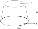
sealing component 4 is a truncated cone-shaped hollow structure with a top surface of 41 and a bottom surface with an opening of 42. As thesealing component 4 is a truncated cone, diameter of the bottom is larger than that of the top; as it has no bottom (bottom is open), there is no bottom constraint on the side near the bottom, which can further add flavor to the aerosol passed through and improve aerosol quality. - At the other end of the aerosol generating product, the
sealing component 4 is directly used to constrain aerosol source-material granules, thesealing component 4 can be directly loaded into theouter tube 5 in the form of filling or compounding without using sealing-film bonding equipment, to avoid the problem that the sealing film is not firmly bonded and easy to fall off. Besides, as thesealing component 4 is a truncated cone, diameter of the bottom is larger than that of the top, it has no bottom (bottom is open), there is no bottom constraint on the side near the bottom, which may naturally expand towards both sides, thereby increasing friction at the contact between thesealing component 4 and the inner wall of theouter tube 5, to ensure that thesealing component 4 is more secure inside theouter tube 5. - Preferably, an
inner tube 25 is also disposed inside thehollow cavity 22, and theplugging part 24 is located inside theinner tube 25. Theinner tube 25 can prevent the pluggingpart 24 from directly contacting the groovecorrugated component 2. - The plugging
part 24 is a bead, and the gap in thehollow cavity 22 without filling the bead forms asecond airflow channel 26. Thefirst airflow channel 23 and thesecond airflow channel 26 work together to gather and accommodate aerosols, and ensure that the generated aerosols can be smoothly sent to the filtering section. - The radial size of the smallest granule of the aerosol source-
material granule 3 is larger than the longest radial distance in thesecond airflow channel 26, so that the aerosol source-material granule 3 does not fall into the groovecorrugated component 2 through thesecond airflow channel 26. - Preferably, the bead is one or a plurality of flavoring bead(s). during smoking, beads are automatically ruptured by heating or manually crushed by consumers to release aroma substances within. Even though beads rupture may weaken plugging of aerosol source-material granules, which has no influence on the cigarette in general, as consumers usually bow their heads or look horizontally during smoking, no one may raise their heads and lift aerosol generating products, thus it is necessary to ensure constraint on aerosol source materials during transportation and storage. Besides, an accidental effect of the present disclosure is that, beads can constrain aerosol source materials during transportation and storage; during smoking, beads rupture and the
second airflow channel 26 becomes larger, which can increase capacity of accommodating aerosol, thereby increasing the amount of smoke. - Preferably, the
outer tube 5 is made of a permeable material, e.g., permeable forming paper, ambient air can enter the groove corrugatedcomponent 2, the aerosol source-material granule 3 and thesealing component 4 through theouter tube 5. - Preferably, a first side-flow vent-
hole 51 is provided on theouter tube 5 wrapping thesealing component 4, there is(are) one and a plurality of the first side-flow vent-hole(s) 51, the first side-flow vent-hole 51 can further add air from the side. Thesealing component 4 can be permeable or impermeable. When it is permeable, air can enter the aerosol source-material granule 3 through the upstream end face of the aerosol generating product. At this time, preferably, there is a first side-flow vent-hole 51, when thesealing component 4 is impermeable, the first side-flow vent-hole 51 must add air from the side. - Preferably, a second side-flow vent-
hole 52 is provided on theouter tube 5 of the groove corrugatedcomponent 2, there is(are) one and a plurality of second side-flow vent-hole(s) 52 to further add air to the groove corrugatedcomponent 2. - In other words, the
outer tube 5 can be made of a permeable or an impermeable material. When it is made of a permeable material, air can be introduced into theouter tube 5 with its own permeability. When it is made of an impermeable material, air can be introduced into theouter tube 5 by punching theouter tube 5. E.g., as mentioned above, a first side-flow vent-hole 51 is provided on theouter tube 5 of thesealing component 4, or the second side-flow vent-hole 52 is provided on theouter tube 5 of the groove corrugatedcomponent 2. - Preferably, the radial size of the smallest granule of the aerosol source-
material granule 3 is larger than the longest radial distance in thefirst airflow channel 23, so that the aerosol source-material granule 3 does not fall into the groove corrugatedcomponent 2 through thefirst airflow channel 23. - Preferably, the first sheet is selected from, but not limited to paper, polylactic acid sheet or cellulose acetate; the
sealing component 4 is selected from paper, polylactic acid sheet or cellulose acetate. - The aerosol generating products in the present disclosure are more preferably suitable for circumferential resistance heating and electromagnetic heating smoking sets. When circumferential resistance heating smoking sets are used, it is only necessary to place the heating cylinder (heating element) axially on the outside of the aerosol source-
material granule 3. When electromagnetic heating smoking sets are used, it is only necessary to place the receptor that can receive from the magnetic field axially on the outside of the aerosol source-material granule 3, or set it to the aerosol source-material granule 3, or more simply, set the receptor material directly on theouter tube 5 wrapping the aerosol source-material granule 3. - Technical solutions above can be combined freely without contradiction.
- The present disclosure has the following beneficial effects:
- 1. Eliminating multi-hole firmware section and the sealing film, while still constraining granules at both ends by the groove corrugated
component 2 and thesealing component 4, the present disclosure combines the groove corrugated component with bulk aerosol source-material granules for the first time, as a pluggingpart 24 is provided in thehollow cavity 22 of the groove corrugated component, which can constrain aerosol source-material granules without using multi-hole firmware. At the other end, thesealing component 4 is directly used to constrain aerosol source-material granules, thesealing component 4 can be directly loaded into theouter tube 5 in the form of filling or compounding, without using sealing-film bonding equipment, to avoid the problem that the sealing-film is not firmly bonded and falls off. Besides, as thesealing component 4 is a truncated cone, diameter of the bottom is larger than that of the top, as it has no bottom (bottom is open), there is no bottom constraint on the side near the bottom surface, which may naturally expand towards both sides, thereby increasing friction at the contact between the sealingcomponent 4 and the inner wall of theouter tube 5, to ensure that thesealing component 4 is more secure inside theouter tube 5. - 2. In case the plugging
part 24 is a flavoring bead, it can further add flavor to the aerosol passed through and improve aerosol quality. - 3. In case of non-smoking, the bead can constrain aerosol source materials during transportation and storage; during smoking, the bead breaks, the
second airflow channel 26 becomes larger, which can increase capacity of accommodating aerosol, thereby increasing the amount of smoke. - 4. In the preferred embodiment of the present disclosure, a first side-flow vent-
hole 51 is provided on theouter tube 5 wrapping thesealing component 4, there is(are) one and a plurality of the first side-flow vent-hole(s) 51, the first side-flow vent-hole 51 can further add air from the side. A second side-flow vent-hole 52 is provided on theouter tube 5 of the groove corrugatedcomponent 2, there is(are) one and a plurality of second side-flow vent-hole(s) 52 to further add air to the groove corrugatedcomponent 2. - 5. The aerosol generating products in the present disclosure are more preferably suitable for circumferential resistance heating and electromagnetic heating smoking sets. When circumferential resistance heating smoking sets are used, it is only necessary to place the heating cylinder (heating element) axially on the outside of the aerosol source-
material granule 3. When electromagnetic heating smoking sets are used, it is only necessary to place the receptor that can receive from the magnetic field axially on the outside of the aerosol source-material granule 3, or set it to the aerosol source-material granule 3, or more simply, set the receptor material directly on theouter tube 5 wrapping the aerosol source-material granule 3. The present disclosure greatly improves production efficiency. By means of circumferential or electromagnetic heating, granules are avoided from scattering into smoking sets and cleaning of smoking sets. -
-
FIG.1 is a structural schematic view of granular aerosol generating products in the prior art. -
FIG.2 is a three-dimensional schematic view of multi-hole firmware section in granular aerosol generating products in the prior art. -
FIG.3 is a structural schematic view of the sealing-type granular aerosol generating product of the present disclosure. -
FIG.4 is a structural schematic view of the sealing-type granular aerosol generating product of the present disclosure with another structure. -
FIG.5 is a structural schematic view of the sealing-type granular aerosol generating product of the present disclosure with still another structure. -
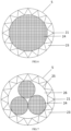
FIG.6 is a structural schematic view of the groove corrugated component of the present disclosure. -
FIG.7 is a structural schematic view of the groove corrugated component of the present disclosure with another structure. -
FIG. 8 is a structural schematic view of thesealing component 4 of the present disclosure. - In
FIGS1-2 : X1-Outer sleeve, X2-Sealing film, X3-Aerosol source-material granules, X4-Multi-hole firmware section, X5-Airflow channel section, X6-Filtering section, X41-Axial through hole, X42-Peripheral ventilation groove; - In
FIGS3-8 : 1-Filtering component, 2-Groove corrugated component, 21-Groove corrugated structure, 22-Hollow cavity, 23-First airflow channel, 24-Plugging part, 25-Inner tube, 26-Second airflow channel, 3-Aerosol source-material granule, 4-Sealing component, 41-Top surface, 42-Opening, 5-Outer tube, 51-First side-flow vent-hole, 52-Second side-flow vent-hole. - The present disclosure is further illustrated through specific embodiment.
- It is understood by those skilled in the art that, the following embodiment is only for illustrating the present disclosure and should not be interpreted as limiting the scope of the present disclosure. In case no specific technique or condition is indicated in the embodiment, the technique or condition described in the literature in the field or the product specification is based on. In case the materials or equipment used are not indicated with manufacturers, they are all ordinary products that can be obtained through purchase.
- It can be understood by those skilled in the art that, the singular forms "a", "an" and "the" used herein can include the plural forms as well, unless expressly stated otherwise. It should be further understood that "including" used in the description of the present disclosure means that the features, integers, steps, operations, elements and/or components exist; however, the existence or addition of one or more other features, integers, steps, operations, elements, components and/or groups thereof is not excluded. It should be understood that, when an element is referred to be "connected" to another one, it may be directly connected to another element, or there may be intermediate elements as well. Moreover, "connection" as used herein may include wireless connections.
- In the description of the present disclosure, unless otherwise stated, "a plurality of" means two or more. The orientation or state relationship indicated by the terms "inside", "above", "below", etc. is based on that shown in the figures, which is only for convenience of describing the present disclosure and simplifying description, rather than indicating or implying that the device or element must have a particular orientation, or must be constructed and operated in a particular orientation, and thus should not be interpreted as limitations of the present disclosure.
- In the description of the present disclosure, it should be noted that, the terms "mount", "connect" and "provided with" should be interpreted broadly unless otherwise expressly specified and defined, such as fixed connection, detachable connection, or integral connection; either mechanical connection or electrical connection; direct connection or indirect connection through intermediate media. The specific meanings of the terms above in the present disclosure can be understood by persons skilled in the art in actual conditions.
- It is understood by those skilled in the art that, unless otherwise defined, all terms including technical and scientific terms used herein have the same meanings as commonly understood by the ordinary persons skilled in the art to the technical field to which the present disclosure belongs. It should also be understood that terms such as those defined in the general dictionary should be understood to have meanings consistent with those in the context of the prior art; moreover, unless defined as herein, the terms may not be explained with idealized or overly formal senses.
- As is shown in
FIGS.3 ,6 and8 , the embodiment provides a sealing-type granular aerosol generating product, which includes afiltering component 1, a groove corrugatedcomponent 2, an aerosol source-material granule 3 and asealing component 4 arranged in turn from the proximal to the distal lip end, anouter sleeve 5 is provided outside each component;
The groove corrugatedcomponent 2 is a cylinder with ahollow cavity 22 surrounded by the first sheet of a groove corrugatedstructure 21. afirst airflow channel 23 that axially penetrates the groove corrugatedstructure 21 forms between the groove corrugatedstructure 21 and theouter tube 5, a pluggingpart 24 is provided in thehollow cavity 22. - Wherein, the upstream and downstream mentioned are determined by the direction of gas flow. More specifically, the distal lip end is upstream and the proximal lip end is downstream.
- The shape of the groove in the groove corrugated
structure 21 is selected from the "V" type, the outer tube is made of paper. - The
sealing component 4 is a truncated cone-shaped hollow structure, it has a top surface of 41 and a bottom surface with an opening of 42. As thesealing component 4 is a truncated cone, diameter of the bottom is larger than that of the top, it has no bottom (bottom is open), there is no bottom constraint on the side near the bottom, which may naturally expand towards both sides, thereby increasing friction at the contact between the sealingcomponent 4 and the inner wall of theouter tube 5, to ensure that thesealing component 4 is more secure inside theouter tube 5. - The
top surface 41 faces the proximal lip side. - The plugging
part 24 is a bead, and the gap in thehollow cavity 22 without filling the bead forms asecond airflow channel 26. Thefirst airflow channel 23 and thesecond airflow channel 26 work together to gather and accommodate aerosols, and ensure that the generated aerosols can be smoothly sent to the filtering section. - The radial size of the smallest granule of the aerosol source-
material granule 3 is smaller than the longest radial distance in thesecond airflow channel 26, so that the aerosol source-material granule 3 does not fall into the groove corrugatedcomponent 2 through thesecond airflow channel 26. - The bead is one flavoring bead.
- The radial size of the smallest granule of the aerosol source-
material granule 3 is smaller than the longest radial distance in thefirst airflow channel 23, so that the aerosol source-material granule 3 does not fall into the groove corrugatedcomponent 2 through thefirst airflow channel 23. - The first sheet is made of paper; the
sealing component 4 is made of paper. - As is shown in
FIG.7 , aninner tube 25 is also disposed inside thehollow cavity 22, and the pluggingpart 24 is located inside theinner tube 25. At this time, the pluggingpart 24 is also a flavoring bead, but the number of the bead is three. Theinner tube 25 can prevent the pluggingpart 24 from directly contacting the groove corrugatedcomponent 2. - As is shown in
FIG.4 , there is a first side-flow vent-hole 51 on theouter tube 5 wrapping thesealing component 4, the number of the first side-flow vent-hole 51 is two, while the first side-flow vent-hole 51 can add air from the side. - As is shown in
FIG.5 , there is a second side-flow vent-hole 52 on theouter tube 5 wrapping the groove corrugatedcomponent 2, the number of the second side-flow vent-hole 52 is two, to further add air into the groove corrugatedcomponent 2. At this time, thetop surface 41 faces the distal lip side. - The aerosol generating products in the embodiment are more preferably suitable for circumferential resistance heating and electromagnetic heating smoking sets. When circumferential resistance heating smoking sets are used, it is only necessary to place the heating cylinder (heating element) axially on the outside of the aerosol source-
material granule 3. When electromagnetic heating smoking sets are used, it is only necessary to place the receptor that can receive from the magnetic field axially on the outside of the aerosol source-material granule 3, or set it to the aerosol source-material granule 3, or more simply, set the receptor material directly on theouter tube 5 wrapping the aerosol source-material granule 3.
Claims (8)
- A sealing-type granular aerosol generating product, the product comprises a filtering component (1), a groove corrugated component (2), an aerosol source-material granular (3) and a sealing component (4) arranged in turn from the proximal to the distal lip end, and an outer tube (5) is provided outside each component;the groove corrugated component (2) is a cylinder with a hollow cavity (22) surrounded by the first sheet of a groove corrugated structure (21), a first airflow channel (23) that axially penetrates the groove corrugated structure (21) forms between the groove corrugated structure (21) and the outer tube (5), a plugging part (24) is provided inside the hollow cavity (22);the sealing component (4) is a truncated cone-shaped hollow structure with a top surface (41) and an opening (42) on the bottom, wherein, the plugging part (24) is a bead, and a gap in the hollow cavity (22) without filling the bead forms a second airflow channel (26); a radial size of the smallest granule of the aerosol source-material granule (3) is larger than the longest radial distance in the second airflow channel (26), so that the aerosol source-material granule (3) does not fall into the groove corrugated component (2) through the second airflow channel (26).
- The granular aerosol generating product of claim 1, wherein, the top surface (41) faces toward a proximal lip side or a distal lip side;
the distal lip end is upstream and the proximal lip end is downstream, wherein the upstream and the downstream are determined by the direction of gas flow. - The granular aerosol generating product of claim 1, wherein, an inner tube (25) is also disposed inside the hollow cavity (22), and the plugging part (24) is located inside the inner tube (25).
- The granular aerosol generating product of claim 1, wherein, the bead(s) is/are one or a plurality of flavoring beads; the first sheet is made of paper, polylactic acid sheet or cellulose acetate; the sealing component (4) is made of paper, polylactic acid sheet or cellulose acetate.
- The granular aerosol generating product of claim 1, wherein, the outer tube (5) is made of permeable materials, ambient air can enter the groove corrugated component (2), the aerosol source-material granule (3) and the sealing component (4) through the outer tube (5).
- The granular aerosol generating product of claim 1, wherein, a first side-flow vent-hole (51) is provided on the outer tube (5) wrapping the sealing component (4), a plurality of first side-flow vent-holes is optional.
- The granular aerosol generating product of claim 1, wherein, there is a second side-flow vent-hole (52) on the outer tube (5) wrapping the groove corrugated component (2), a plurality of second side-flow vent-holes is optional.
- The granular aerosol generating product of claim 1, wherein, the radial size of the smallest granule of the aerosol source-material granule (3) is larger than the longest radial distance in the first airflow channel (23), so that the aerosol source-material granule (3) does not fall into the groove corrugated component (2) through the first airflow channel (23).
Applications Claiming Priority (2)
| Application Number | Priority Date | Filing Date | Title |
|---|---|---|---|
| CN202210253922.8A CN114568743B (en) | 2022-03-15 | 2022-03-15 | A card-sealed particle aerosol generating product |
| PCT/CN2022/098568 WO2023173607A1 (en) | 2022-03-15 | 2022-06-14 | Snap-seal particulate aerosol-generating article |
Publications (3)
| Publication Number | Publication Date |
|---|---|
| EP4272583A1 EP4272583A1 (en) | 2023-11-08 |
| EP4272583A4 EP4272583A4 (en) | 2024-06-19 |
| EP4272583B1 true EP4272583B1 (en) | 2025-05-21 |
Family
ID=81775218
Family Applications (1)
| Application Number | Title | Priority Date | Filing Date |
|---|---|---|---|
| EP22862400.3A Active EP4272583B1 (en) | 2022-03-15 | 2022-06-14 | Snap-seal particulate aerosol-generating article |
Country Status (3)
| Country | Link |
|---|---|
| EP (1) | EP4272583B1 (en) |
| CN (1) | CN114568743B (en) |
| WO (1) | WO2023173607A1 (en) |
Families Citing this family (3)
| Publication number | Priority date | Publication date | Assignee | Title |
|---|---|---|---|---|
| CN114568743B (en) * | 2022-03-15 | 2025-10-03 | 云南中烟工业有限责任公司 | A card-sealed particle aerosol generating product |
| CN114847543A (en) * | 2022-06-21 | 2022-08-05 | 云南中烟工业有限责任公司 | Aerosol generating article with composite form closure |
| CN115191658A (en) * | 2022-08-15 | 2022-10-18 | 湖北中烟工业有限责任公司 | Cigarette not burning by heating |
Family Cites Families (16)
| Publication number | Priority date | Publication date | Assignee | Title |
|---|---|---|---|---|
| KR102709311B1 (en) * | 2017-05-10 | 2024-09-25 | 필립모리스 프로덕츠 에스.에이. | Aerosol-generating articles, devices and systems for use with multiple aerosol-forming substrates |
| CN112469292A (en) * | 2018-07-26 | 2021-03-09 | Jt国际股份公司 | Method and apparatus for manufacturing aerosol-generating articles |
| WO2020202257A1 (en) * | 2019-03-29 | 2020-10-08 | 日本たばこ産業株式会社 | Cooling segment, non-combustion heating type flavor inhalation article, method for using non-combustion heating type flavor inhalation article, and non-combustion heating type flavor inhalation system |
| JP6969031B2 (en) * | 2019-04-18 | 2021-11-24 | 日本たばこ産業株式会社 | Heat-not-burn tobacco |
| CN210275873U (en) * | 2019-04-28 | 2020-04-10 | 云南中烟工业有限责任公司 | A heat-not-burn cigarette |
| CN109965366A (en) * | 2019-05-10 | 2019-07-05 | 博颉(上海)管理咨询有限公司 | Heat cigarette of not burning |
| CN110367587B (en) * | 2019-07-18 | 2024-05-31 | 索图电子(惠州)有限公司 | Flue gas treatment part, low-temperature non-combustible particle type cigarette using same and production process thereof |
| CN111165891A (en) * | 2019-12-30 | 2020-05-19 | 云南米云生物科技有限公司 | Composite cigarette containing granular type heating non-combustible capsule and preparation method thereof |
| CN212697654U (en) * | 2020-09-18 | 2021-03-16 | 新火智造(深圳)有限公司 | Integrated heating non-combustion cigarette |
| CN213848760U (en) * | 2020-11-03 | 2021-08-03 | 云南喜科科技有限公司 | Aerosol generating article of bulk smoking material |
| CN112754075A (en) * | 2020-12-15 | 2021-05-07 | 深圳香满路健康科技有限公司 | Cigarette bullet and electron cigarette with cavity filtration |
| CN113662239A (en) * | 2021-09-23 | 2021-11-19 | 云南中烟工业有限责任公司 | An aerosol-generating article flavored with a core segment |
| CN113662240A (en) * | 2021-09-23 | 2021-11-19 | 云南中烟工业有限责任公司 | A kind of aerosol-generating product flavored by puncture-type cigarette core section |
| CN113925197B (en) * | 2021-11-30 | 2025-03-21 | 云南中烟工业有限责任公司 | An aerosol generating product having a particle-type aerosol generating matrix rod with high porosity |
| CN217284737U (en) * | 2022-03-15 | 2022-08-26 | 云南中烟工业有限责任公司 | Card-sealed particle-type aerosol-generating article |
| CN114568743B (en) * | 2022-03-15 | 2025-10-03 | 云南中烟工业有限责任公司 | A card-sealed particle aerosol generating product |
-
2022
- 2022-03-15 CN CN202210253922.8A patent/CN114568743B/en active Active
- 2022-06-14 EP EP22862400.3A patent/EP4272583B1/en active Active
- 2022-06-14 WO PCT/CN2022/098568 patent/WO2023173607A1/en not_active Ceased
Also Published As
| Publication number | Publication date |
|---|---|
| EP4272583A4 (en) | 2024-06-19 |
| WO2023173607A1 (en) | 2023-09-21 |
| CN114568743B (en) | 2025-10-03 |
| CN114568743A (en) | 2022-06-03 |
| EP4272583A1 (en) | 2023-11-08 |
Similar Documents
| Publication | Publication Date | Title |
|---|---|---|
| CN114468351B (en) | A granular aerosol generating product having a grooved corrugated component | |
| EP4272583A1 (en) | Snap-seal particulate aerosol-generating article | |
| CN113925196B (en) | An aerosol generating product with a segmented aerosol generating matrix rod | |
| WO2022095189A1 (en) | Inner component of multi-purpose aerosol generating product, and aerosol generating product comprising same | |
| JP6888075B2 (en) | Smoking items including flow limiters | |
| CN217161062U (en) | Particle-blocking aerosol-generating article | |
| CN213819844U (en) | Aerosol generating product of bulk filter material | |
| CN114886158A (en) | Aerosol generating product with variable-diameter airflow channel plugging piece | |
| CN115363244B (en) | Device for generating smoke for suction | |
| CN217284737U (en) | Card-sealed particle-type aerosol-generating article | |
| CN216961478U (en) | Heating cigarette | |
| CN216165132U (en) | Independent smoking section and pluggable split type cigarette comprising same | |
| CN222367052U (en) | A three-stage particle aerosol generating product and aerosol generating system | |
| CN221887692U (en) | A composite aerosol generating product of an empty pipe and a filter | |
| CN114568742A (en) | Aerosol-generating article with self-formed smoking segment and method of making same | |
| CN117179370B (en) | Smoke generating section, manufacturing method and application thereof | |
| CN222017690U (en) | Two-stage particle type aerosol generating product and aerosol generating system | |
| CN217509862U (en) | Smoking section | |
| EP4193852B1 (en) | Double-layered heating cigarette, and preparation method therefor and use thereof | |
| CN217509889U (en) | Middle-segment particle type aerosol generating product and combined set comprising same | |
| CN217218179U (en) | Blanking type particle aerosol generating product and aerosol generating system | |
| CN219894662U (en) | A kind of perforated and ventilated particle type heated cigarette | |
| CN114847531A (en) | Blanking type particle type aerosol generating product with spiral structure and aerosol generating system | |
| CN216961479U (en) | Aerosol-generating article with capsule closure | |
| EP4278911B1 (en) | Blanking-type particulate aerosol generating article and aerosol generating system |
Legal Events
| Date | Code | Title | Description |
|---|---|---|---|
| STAA | Information on the status of an ep patent application or granted ep patent |
Free format text: STATUS: UNKNOWN |
|
| STAA | Information on the status of an ep patent application or granted ep patent |
Free format text: STATUS: THE INTERNATIONAL PUBLICATION HAS BEEN MADE |
|
| PUAI | Public reference made under article 153(3) epc to a published international application that has entered the european phase |
Free format text: ORIGINAL CODE: 0009012 |
|
| STAA | Information on the status of an ep patent application or granted ep patent |
Free format text: STATUS: REQUEST FOR EXAMINATION WAS MADE |
|
| 17P | Request for examination filed |
Effective date: 20230310 |
|
| AK | Designated contracting states |
Kind code of ref document: A1 Designated state(s): AL AT BE BG CH CY CZ DE DK EE ES FI FR GB GR HR HU IE IS IT LI LT LU LV MC MK MT NL NO PL PT RO RS SE SI SK SM TR |
|
| STAA | Information on the status of an ep patent application or granted ep patent |
Free format text: STATUS: EXAMINATION IS IN PROGRESS |
|
| A4 | Supplementary search report drawn up and despatched |
Effective date: 20240516 |
|
| RIC1 | Information provided on ipc code assigned before grant |
Ipc: A24D 1/20 20200101AFI20240511BHEP |
|
| 17Q | First examination report despatched |
Effective date: 20240528 |
|
| GRAP | Despatch of communication of intention to grant a patent |
Free format text: ORIGINAL CODE: EPIDOSNIGR1 |
|
| STAA | Information on the status of an ep patent application or granted ep patent |
Free format text: STATUS: GRANT OF PATENT IS INTENDED |
|
| DAV | Request for validation of the european patent (deleted) | ||
| DAX | Request for extension of the european patent (deleted) | ||
| INTG | Intention to grant announced |
Effective date: 20250116 |
|
| GRAS | Grant fee paid |
Free format text: ORIGINAL CODE: EPIDOSNIGR3 |
|
| GRAA | (expected) grant |
Free format text: ORIGINAL CODE: 0009210 |
|
| STAA | Information on the status of an ep patent application or granted ep patent |
Free format text: STATUS: THE PATENT HAS BEEN GRANTED |
|
| AK | Designated contracting states |
Kind code of ref document: B1 Designated state(s): AL AT BE BG CH CY CZ DE DK EE ES FI FR GB GR HR HU IE IS IT LI LT LU LV MC MK MT NL NO PL PT RO RS SE SI SK SM TR |
|
| P01 | Opt-out of the competence of the unified patent court (upc) registered |
Free format text: CASE NUMBER: APP_17966/2025 Effective date: 20250414 |
|
| REG | Reference to a national code |
Ref country code: GB Ref legal event code: FG4D |
|
| REG | Reference to a national code |
Ref country code: CH Ref legal event code: EP |
|
| REG | Reference to a national code |
Ref country code: DE Ref legal event code: R096 Ref document number: 602022015069 Country of ref document: DE |
|
| REG | Reference to a national code |
Ref country code: IE Ref legal event code: FG4D |
|
| PGFP | Annual fee paid to national office [announced via postgrant information from national office to epo] |
Ref country code: AT Payment date: 20250721 Year of fee payment: 4 |
|
| REG | Reference to a national code |
Ref country code: NL Ref legal event code: MP Effective date: 20250521 |
|
| PG25 | Lapsed in a contracting state [announced via postgrant information from national office to epo] |
Ref country code: FI Free format text: LAPSE BECAUSE OF FAILURE TO SUBMIT A TRANSLATION OF THE DESCRIPTION OR TO PAY THE FEE WITHIN THE PRESCRIBED TIME-LIMIT Effective date: 20250521 Ref country code: PT Free format text: LAPSE BECAUSE OF FAILURE TO SUBMIT A TRANSLATION OF THE DESCRIPTION OR TO PAY THE FEE WITHIN THE PRESCRIBED TIME-LIMIT Effective date: 20250922 Ref country code: ES Free format text: LAPSE BECAUSE OF FAILURE TO SUBMIT A TRANSLATION OF THE DESCRIPTION OR TO PAY THE FEE WITHIN THE PRESCRIBED TIME-LIMIT Effective date: 20250521 |
|
| REG | Reference to a national code |
Ref country code: LT Ref legal event code: MG9D |
|
| PG25 | Lapsed in a contracting state [announced via postgrant information from national office to epo] |
Ref country code: GR Free format text: LAPSE BECAUSE OF FAILURE TO SUBMIT A TRANSLATION OF THE DESCRIPTION OR TO PAY THE FEE WITHIN THE PRESCRIBED TIME-LIMIT Effective date: 20250822 Ref country code: NO Free format text: LAPSE BECAUSE OF FAILURE TO SUBMIT A TRANSLATION OF THE DESCRIPTION OR TO PAY THE FEE WITHIN THE PRESCRIBED TIME-LIMIT Effective date: 20250821 |
|
| PG25 | Lapsed in a contracting state [announced via postgrant information from national office to epo] |
Ref country code: NL Free format text: LAPSE BECAUSE OF FAILURE TO SUBMIT A TRANSLATION OF THE DESCRIPTION OR TO PAY THE FEE WITHIN THE PRESCRIBED TIME-LIMIT Effective date: 20250521 Ref country code: PL Free format text: LAPSE BECAUSE OF FAILURE TO SUBMIT A TRANSLATION OF THE DESCRIPTION OR TO PAY THE FEE WITHIN THE PRESCRIBED TIME-LIMIT Effective date: 20250521 |
|
| PGFP | Annual fee paid to national office [announced via postgrant information from national office to epo] |
Ref country code: IT Payment date: 20250630 Year of fee payment: 4 |
|
| PG25 | Lapsed in a contracting state [announced via postgrant information from national office to epo] |
Ref country code: BG Free format text: LAPSE BECAUSE OF FAILURE TO SUBMIT A TRANSLATION OF THE DESCRIPTION OR TO PAY THE FEE WITHIN THE PRESCRIBED TIME-LIMIT Effective date: 20250521 |
|
| PG25 | Lapsed in a contracting state [announced via postgrant information from national office to epo] |
Ref country code: HR Free format text: LAPSE BECAUSE OF FAILURE TO SUBMIT A TRANSLATION OF THE DESCRIPTION OR TO PAY THE FEE WITHIN THE PRESCRIBED TIME-LIMIT Effective date: 20250521 |
|
| PG25 | Lapsed in a contracting state [announced via postgrant information from national office to epo] |
Ref country code: RS Free format text: LAPSE BECAUSE OF FAILURE TO SUBMIT A TRANSLATION OF THE DESCRIPTION OR TO PAY THE FEE WITHIN THE PRESCRIBED TIME-LIMIT Effective date: 20250821 |
|
| PG25 | Lapsed in a contracting state [announced via postgrant information from national office to epo] |
Ref country code: IS Free format text: LAPSE BECAUSE OF FAILURE TO SUBMIT A TRANSLATION OF THE DESCRIPTION OR TO PAY THE FEE WITHIN THE PRESCRIBED TIME-LIMIT Effective date: 20250921 |
|
| PG25 | Lapsed in a contracting state [announced via postgrant information from national office to epo] |
Ref country code: LV Free format text: LAPSE BECAUSE OF FAILURE TO SUBMIT A TRANSLATION OF THE DESCRIPTION OR TO PAY THE FEE WITHIN THE PRESCRIBED TIME-LIMIT Effective date: 20250521 |
|
| REG | Reference to a national code |
Ref country code: AT Ref legal event code: MK05 Ref document number: 1795990 Country of ref document: AT Kind code of ref document: T Effective date: 20250521 |
|
| REG | Reference to a national code |
Ref country code: DE Ref legal event code: R119 Ref document number: 602022015069 Country of ref document: DE |
|
| PG25 | Lapsed in a contracting state [announced via postgrant information from national office to epo] |
Ref country code: AT Free format text: LAPSE BECAUSE OF FAILURE TO SUBMIT A TRANSLATION OF THE DESCRIPTION OR TO PAY THE FEE WITHIN THE PRESCRIBED TIME-LIMIT Effective date: 20250521 Ref country code: DK Free format text: LAPSE BECAUSE OF FAILURE TO SUBMIT A TRANSLATION OF THE DESCRIPTION OR TO PAY THE FEE WITHIN THE PRESCRIBED TIME-LIMIT Effective date: 20250521 Ref country code: SM Free format text: LAPSE BECAUSE OF FAILURE TO SUBMIT A TRANSLATION OF THE DESCRIPTION OR TO PAY THE FEE WITHIN THE PRESCRIBED TIME-LIMIT Effective date: 20250521 |
|
| PG25 | Lapsed in a contracting state [announced via postgrant information from national office to epo] |
Ref country code: CZ Free format text: LAPSE BECAUSE OF FAILURE TO SUBMIT A TRANSLATION OF THE DESCRIPTION OR TO PAY THE FEE WITHIN THE PRESCRIBED TIME-LIMIT Effective date: 20250521 |
|
| PG25 | Lapsed in a contracting state [announced via postgrant information from national office to epo] |
Ref country code: EE Free format text: LAPSE BECAUSE OF FAILURE TO SUBMIT A TRANSLATION OF THE DESCRIPTION OR TO PAY THE FEE WITHIN THE PRESCRIBED TIME-LIMIT Effective date: 20250521 |
|
| PG25 | Lapsed in a contracting state [announced via postgrant information from national office to epo] |
Ref country code: SK Free format text: LAPSE BECAUSE OF FAILURE TO SUBMIT A TRANSLATION OF THE DESCRIPTION OR TO PAY THE FEE WITHIN THE PRESCRIBED TIME-LIMIT Effective date: 20250521 |
|
| REG | Reference to a national code |
Ref country code: CH Ref legal event code: H13 Free format text: ST27 STATUS EVENT CODE: U-0-0-H10-H13 (AS PROVIDED BY THE NATIONAL OFFICE) Effective date: 20260127 |
|
| PG25 | Lapsed in a contracting state [announced via postgrant information from national office to epo] |
Ref country code: LU Free format text: LAPSE BECAUSE OF NON-PAYMENT OF DUE FEES Effective date: 20250614 |
|
| PG25 | Lapsed in a contracting state [announced via postgrant information from national office to epo] |
Ref country code: MC Free format text: LAPSE BECAUSE OF FAILURE TO SUBMIT A TRANSLATION OF THE DESCRIPTION OR TO PAY THE FEE WITHIN THE PRESCRIBED TIME-LIMIT Effective date: 20250521 |
|
| REG | Reference to a national code |
Ref country code: BE Ref legal event code: MM Effective date: 20250630 |
|
| PG25 | Lapsed in a contracting state [announced via postgrant information from national office to epo] |
Ref country code: RO Free format text: LAPSE BECAUSE OF FAILURE TO SUBMIT A TRANSLATION OF THE DESCRIPTION OR TO PAY THE FEE WITHIN THE PRESCRIBED TIME-LIMIT Effective date: 20250521 |
|
| PLBE | No opposition filed within time limit |
Free format text: ORIGINAL CODE: 0009261 |
|
| STAA | Information on the status of an ep patent application or granted ep patent |
Free format text: STATUS: NO OPPOSITION FILED WITHIN TIME LIMIT |
|
| REG | Reference to a national code |
Ref country code: CH Ref legal event code: L10 Free format text: ST27 STATUS EVENT CODE: U-0-0-L10-L00 (AS PROVIDED BY THE NATIONAL OFFICE) Effective date: 20260402 |
|
| PG25 | Lapsed in a contracting state [announced via postgrant information from national office to epo] |
Ref country code: IE Free format text: LAPSE BECAUSE OF NON-PAYMENT OF DUE FEES Effective date: 20250614 Ref country code: DE Free format text: LAPSE BECAUSE OF NON-PAYMENT OF DUE FEES Effective date: 20260101 |
|
| PG25 | Lapsed in a contracting state [announced via postgrant information from national office to epo] |
Ref country code: BE Free format text: LAPSE BECAUSE OF NON-PAYMENT OF DUE FEES Effective date: 20250630 |
|
| PG25 | Lapsed in a contracting state [announced via postgrant information from national office to epo] |
Ref country code: FR Free format text: LAPSE BECAUSE OF NON-PAYMENT OF DUE FEES Effective date: 20250721 |
|
| PG25 | Lapsed in a contracting state [announced via postgrant information from national office to epo] |
Ref country code: CH Free format text: LAPSE BECAUSE OF NON-PAYMENT OF DUE FEES Effective date: 20250630 |
|
| 26N | No opposition filed |
Effective date: 20260224 |