EP4272536A1 - Means for adjusting cutting height of a powered lawn mower - Google Patents
Means for adjusting cutting height of a powered lawn mower Download PDFInfo
- Publication number
- EP4272536A1 EP4272536A1 EP23152253.3A EP23152253A EP4272536A1 EP 4272536 A1 EP4272536 A1 EP 4272536A1 EP 23152253 A EP23152253 A EP 23152253A EP 4272536 A1 EP4272536 A1 EP 4272536A1
- Authority
- EP
- European Patent Office
- Prior art keywords
- lawn mower
- cutting disc
- rotation axis
- common rotation
- knob
- Prior art date
- Legal status (The legal status is an assumption and is not a legal conclusion. Google has not performed a legal analysis and makes no representation as to the accuracy of the status listed.)
- Granted
Links
Images


Classifications
-
- A—HUMAN NECESSITIES
- A01—AGRICULTURE; FORESTRY; ANIMAL HUSBANDRY; HUNTING; TRAPPING; FISHING
- A01D—HARVESTING; MOWING
- A01D34/00—Mowers; Mowing apparatus of harvesters
- A01D34/01—Mowers; Mowing apparatus of harvesters characterised by features relating to the type of cutting apparatus
- A01D34/412—Mowers; Mowing apparatus of harvesters characterised by features relating to the type of cutting apparatus having rotating cutters
- A01D34/63—Mowers; Mowing apparatus of harvesters characterised by features relating to the type of cutting apparatus having rotating cutters having cutters rotating about a vertical axis
- A01D34/73—Cutting apparatus
-
- A—HUMAN NECESSITIES
- A01—AGRICULTURE; FORESTRY; ANIMAL HUSBANDRY; HUNTING; TRAPPING; FISHING
- A01D—HARVESTING; MOWING
- A01D34/00—Mowers; Mowing apparatus of harvesters
- A01D34/01—Mowers; Mowing apparatus of harvesters characterised by features relating to the type of cutting apparatus
- A01D34/412—Mowers; Mowing apparatus of harvesters characterised by features relating to the type of cutting apparatus having rotating cutters
- A01D34/63—Mowers; Mowing apparatus of harvesters characterised by features relating to the type of cutting apparatus having rotating cutters having cutters rotating about a vertical axis
- A01D34/74—Cutting-height adjustment
-
- A—HUMAN NECESSITIES
- A01—AGRICULTURE; FORESTRY; ANIMAL HUSBANDRY; HUNTING; TRAPPING; FISHING
- A01D—HARVESTING; MOWING
- A01D34/00—Mowers; Mowing apparatus of harvesters
- A01D34/006—Control or measuring arrangements
- A01D34/008—Control or measuring arrangements for automated or remotely controlled operation
-
- A—HUMAN NECESSITIES
- A01—AGRICULTURE; FORESTRY; ANIMAL HUSBANDRY; HUNTING; TRAPPING; FISHING
- A01D—HARVESTING; MOWING
- A01D34/00—Mowers; Mowing apparatus of harvesters
- A01D34/01—Mowers; Mowing apparatus of harvesters characterised by features relating to the type of cutting apparatus
- A01D34/412—Mowers; Mowing apparatus of harvesters characterised by features relating to the type of cutting apparatus having rotating cutters
- A01D34/63—Mowers; Mowing apparatus of harvesters characterised by features relating to the type of cutting apparatus having rotating cutters having cutters rotating about a vertical axis
- A01D34/76—Driving mechanisms for the cutters
- A01D34/78—Driving mechanisms for the cutters electric
-
- A—HUMAN NECESSITIES
- A01—AGRICULTURE; FORESTRY; ANIMAL HUSBANDRY; HUNTING; TRAPPING; FISHING
- A01D—HARVESTING; MOWING
- A01D34/00—Mowers; Mowing apparatus of harvesters
- A01D34/01—Mowers; Mowing apparatus of harvesters characterised by features relating to the type of cutting apparatus
- A01D34/412—Mowers; Mowing apparatus of harvesters characterised by features relating to the type of cutting apparatus having rotating cutters
- A01D34/63—Mowers; Mowing apparatus of harvesters characterised by features relating to the type of cutting apparatus having rotating cutters having cutters rotating about a vertical axis
- A01D34/82—Other details
-
- A—HUMAN NECESSITIES
- A01—AGRICULTURE; FORESTRY; ANIMAL HUSBANDRY; HUNTING; TRAPPING; FISHING
- A01D—HARVESTING; MOWING
- A01D2101/00—Lawn-mowers
Definitions
- the present disclosure relates to a powered lawn mower, for example a robotic lawn mower, where the cutting height can be easily adjusted by a user.
- Grass cutting machines are for used for both domestic and commercial applications and can be powered using an electric motor or an internal combustion engine.
- a so-called rotary cutter employs a cutting member which is rotatable in a plane substantially parallel to the ground and about an axis which is normal to the ground, where the cutting member comprises an arm or a disc that is rotatably supported in its center and has cutting edges arranged at its ends or its circumference.
- Automated or robotic power tools such as robotic lawn mowers are becoming increasingly more popular.
- a work area such as a garden
- the work area is enclosed by a boundary wire with the purpose of keeping the robotic lawn mower inside the work area.
- An electric control signal may be transmitted through the boundary wire thereby generating an (electro-) magnetic field emanating from the boundary wire.
- the robotic working tool is typically arranged with one or more sensors adapted to sense the control signal.
- the robotic lawn mower can then cut grass on a user's lawn automatically and can be charged automatically without intervention of the user, and no longer needs to be manually managed after being set once.
- the robotic lawn mower typically comprises charging skids for contacting corresponding contact plates in a charging station when docking into the charging station for receiving a charging current through, and possibly also for transferring information by means of electrical communication between the charging station and the robotic lawn mower.
- Most conventional lawn mowers include some means for adjusting the grass cutting height since different users like to cut their lawns to different lengths, and to cut different areas of their lawns to different lengths. This can depend on grow rate of the grass and the cutting frequency of a particular area, as well as on general user desires regarding height of cut grass.
- Most lawn mowers includes means for providing an adjustable height of cutting height, for example wheels or rollers can be connected to a housing in a number of different positions, each position corresponding to a different height of cut, but requires a large number of components in order to adjust the height, and is thus expensive to manufacture.
- Cutting height adjustment can also be made by inserting or removing spacers between the cutter blade and the drive shaft to which the cutter blade is fastened.
- the adjustment involves unbolting the blade from the drive shaft, inserting or removing spacers, and bolting the blade back onto the drive shaft. This operation is relatively cumbersome and time consuming, and requires spacers to be stored.
- EP 531071 discloses displacing a cutting member against a compression spring so as to alter the height of cut of mown grass
- EP 766911 discloses displacing the chassis of a lawn mower to alter the height of cut of mown grass.
- EP 3935933 discloses a lawn mower comprising at least two engagement plateau arrangements which are connected to a cutting disc, mutually separated along a vertical extension and adapted to receive a coupling member comprised in the transmission axle. This enables the cutting disc to obtain a certain vertical position in dependence of which engagement plateau arrangement that has received the coupling member that is secured by means of screws.
- CN 103621244 discloses a mower with a cutterhead and a transmission part that is provided with a matching-connecting face which is connected with the cutterhead in a matched mode.
- the cutterhead is provided with a first installation face and a second installation face, one on each side of the cutter head, for abutting connection with the matching-connecting face.
- the object of the present disclosure is to provide improved and alternative means for setting a grass cutting height of a lawn mower in a more versatile, uncomplicated and efficient manner than previously presented, needing lesser parts and no special tools.
- a lawn mower cutter unit comprising a cutter propulsion unit with a transmission axle that is adapted to be rotated around a common rotation axis, a hub that is rotatably connected to the transmission axle, a cutting disc, and a knob.
- the knob is rotatably connected to the hub such that the knob is adapted to rotate with the hub and the transmission axle.
- the cutting disc is displaceable along the common rotation axis, against a spring force of a spring element.
- the cutting disc and the knob are comprised in a coupling interface that is comprised in the lawn mower cutter unit and adapted to transfer a rotational torque transferred from the hub to the cutting disc.
- the coupling interface is adapted to releasably lock the cutting disc in mutually separated positions along the common rotation axis by means of the spring force, conferring an associated certain grass cutting height for each locked position.
- the grass cutting height can be adjusted by displacing the cutting disc 160 along the common rotation axis Ax and locking the cutting disc 160 in a position that corresponds to a desired grass cutting height.
- the cutting disc comprises a connection portion that comprises an aperture and at least two engagement recesses which are formed in the aperture and extend to at last two mutually different depths parallel to the common rotation axis.
- the knob comprises at least one coupling protrusion that extends away from the common rotation axis and is adapted to transfer a rotational torque transferred from the hub to the cutting disc via a corresponding engagement recess.
- the recesses are adapted to receive said coupling protrusion in at least two different mounting positions along the common rotation axis. The mounting positions are locked by means of the spring force such that the cutting disc obtains a certain vertical position along the common rotation axis in dependence of which engagement recess that has received the corresponding coupling protrusion.
- the grass cutting height can be adjusted by displacing the cutting disc 160 along the common rotation axis Ax and locking the cutting disc 160 in a position that corresponds to a desired grass cutting height without the need of any tools.
- the lawn mower cutter unit further comprises a cover adapted to seal an end of the aperture that is adapted to face the ground surface during operation of the lawn mower cutter unit.
- the common rotation axis extends through a centre portion of the knob. This means that the knob has a symmetrical position with respect to the coupling interface.
- connection portion comprises at least two pairs of opposing engagement recesses, each pair of opposing engagement recesses having the same depth along the common rotation axis.
- knob comprises two opposing coupling protrusions which are adapted to engage a pair of opposing engagement recesses.
- This provides a secure transfer of rotational torque from the knob to the cutting disc via the coupling protrusions when engaging a pair of opposing engagement recesses.
- the coupling interface comprises the spring element that is adapted to encompass the hub, the knob, the recesses, a first spring element holder and a second spring element holder.
- the first spring element holder is a retainer ring that is adapted to rest against a motor flange comprised in the cutter propulsion unit and the second spring element holder is comprised in the connection portion.
- the spring element is in the form of a helical spring that is positioned between the spring element holders.
- the coupling interface comprises a bushing that is adapted to be positioned in the connection portion and to circumvent the hub.
- the bushing stabilizes the hub.
- the cutting disc is displaceable along the common rotation axis, against the spring force of the spring element, when displaced towards the cutter propulsion unit. This means that the spring force urges the cutting disc away from the cutter propulsion unit and enables an uncomplicated design and easily managed setting of grass cutting height
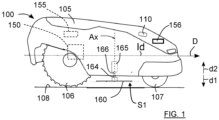
- FIG. 1 schematically illustrates a lawnmower 100 according to some embodiments of the present disclosure.
- the lawnmower 100 is a self-propelled autonomous robotic lawnmower 100 capable of navigating and cutting grass in an autonomous manner in an area without the intervention or the control of a user.
- This can be enabled by means of one or more environmental detection sensors such as Lidar, radar and/or ultrasonic sensors, as well as boundary wire sensors adapted to sense boundary wire control signals.
- navigation devices such as GPS (Global Positioning System) devices can also be used.
- GPS Global Positioning System
- Figure 1 shows a schematic side view of a robotic lawn mower 100 that is adapted for a forward travelling direction D, has a body 105 and a plurality of wheels 106, 107; in this example the robotic lawn mower 100 has four wheels 106, 107, two rear wheels 106 and two front wheels 107 which wheels 106, 107 here are shown in contact with a flat ground surface 108.
- the robotic lawn mower 100 comprises a control unit 110 and a first electrical motor 150 that is adapted to provide motive power and/or steering of the robotic lawn mower 100.
- the rear wheels 106 are powered and constitute drive wheels, and steering may be achieved by rotating the rear wheels 106 in different directions.
- Wheels that are not powered, here the front wheels 106 constitute support wheels which can be in the form of pivotable castor wheels that follow the travel direction D.
- the robotic lawn mower 100 may be provided with another number of wheels, such as three wheels. Moreover, according to further embodiments, the robotic lawn mower 100 may be provided with another configuration of driven and non-driven wheels, such as a front wheel drive or an all-wheel drive.
- control unit 110 may be configured to control propulsion of the robotic lawn mower 100, and steer the robotic lawn mower 100, by controlling the drive wheels 106 of the robotic lawn mower 100.
- combustion engines may alternatively be used in combination with an electric motor arrangement.
- the robotic lawn mower 100 comprises charging skids 156 for contacting contact plates of a charging station (not shown) when docking into the charging station for receiving a charging current, and possibly also for transferring information by means of electrical communication between the charging station and the robotic lawn mower 100.
- the robotic lawn mower 100 also comprises at least one rechargeable electric power source such as a battery 155 for providing power to the electric motor arrangement 150.
- the battery 155 is arranged to be charged by means of received charging current from the charging station, received through the charging skids 156 or other suitable charging connectors.
- the robotic lawn mower 100 also comprises a lawn mower cutter unit 102 that comprises a grass cutting device 160 and a cutter motor 165, or more generally, a cutter propulsion unit 165, that also is powered by the battery 155 or, alternatively, by a separate power source.
- the cutter propulsion unit 165 is adapted to drive the cutter propulsion unit 165 and comprises a transmission axle 169 that is adapted to be rotated around a common rotation axis Ax.
- the grass cutting device 160 is constituted by a cutting disc 160 that according to some aspects comprises a plurality of cutting edges such as cutting knifes 123, 124, 125.
- each cutting knife 123, 124, 125 is pivotally arranged such that during normal operation they are maintained at a working position due to centripetal forces, radially extending outwards from the cutting disc's center.
- Many types of cutting edges and number of cutting edges are of course conceivable.
- the lawn mower cutter unit 102 comprises a hub 166 that is rotatably connected to the transmission axle 169, a knob 120 that is rotatably connected to the hub 166 such that the knob 120 is adapted to rotate with the hub 166 and the transmission axle 169.
- the cutting disc 160 is displaceable along the common rotation axis Ax, against a spring force of a spring element 130.
- the cutting disc 160 and the knob 120 are comprised in a coupling interface 140 that is adapted to transfer a rotational torque transferred from the hub 166 to the cutting disc 160.
- the coupling interface 140 is adapted to releasably lock the cutting disc 160 in mutually separated positions along the common rotation axis Ax by means of the spring force, conferring an associated certain grass cutting height for each locked position.
- the coupling interface 140 is comprised in the lawn mower cutter unit 102.
- the grass cutting height can be adjusted by displacing the cutting disc 160 along the common rotation axis Ax and locking the cutting disc 160 in a positioned that corresponds to a desired grass cutting height.
- the cutting disc 160 comprises a connection portion 164 that comprises an aperture 161 and at least two engagement recesses 171a, 171b; 172a, 172b; 173a, 173b; 174a, 174b; 175a, 175b which are formed in the aperture 161 and extend to at last two mutually different depths parallel to the common rotation axis Ax.
- the knob 120 comprises at least one coupling protrusion 121, 122 that extends away from the common rotation axis Ax and is adapted to transfer a rotational torque transferred from the hub 166 to the cutting disc 160 via a corresponding engagement recess 171a, 171b; 172a, 172b; 173a, 173b; 174a, 174b; 175a, 175b.
- the recesses 171a, 171b; 172a, 172b; 173a, 173b; 174a, 174b; 175a, 175b are adapted to receive said coupling protrusion 121,122 in at least two different mounting positions along the common rotation axis Ax, where the mounting positions are locked by means of the spring force such that the cutting disc 160 obtains a certain vertical position along the common rotation axis Ax in dependence of which engagement recess 171a, 171b; 172a, 172b; 173a, 173b; 174a, 174b; 175a, 175b that has received the corresponding coupling protrusion 121, 122.
- the grass cutting height can be adjusted by displacing the cutting disc 160 along the common rotation axis Ax and locking the cutting disc 160 in a positioned that corresponds to a desired grass cutting height without the need of any tools.
- the cutting disc 160 is displaceable along the common rotation axis Ax, against the spring force of the spring element 130, when displaced towards the cutter propulsion unit 165. This means that the spring force urges the cutting disc away from the cutter propulsion unit 165 and enables an uncomplicated design and easily managed setting of grass cutting height. This is the case for the example illustrated in Figure 2-9 .
- the cutting disc 160 is displaceable along the common rotation axis Ax, against a spring force of a spring element, when displaced away from the cutter propulsion unit 165, for example pulled towards a user, when adjusting the grass cutting height.
- the coupling interface 140 has to be designed accordingly, for example the recesses will have to run in an opposite direction along the common rotation axis Ax. The details of such a design are not described here, but can of course easily be implemented by the skilled person.
- connection portion 164 comprises at least two pairs of opposing engagement recesses 171a, 171b; 172a, 172b; 173a, 173b; 174a, 174b; 175a, 175b, each pair of opposing engagement recesses 171a, 171b; 172a, 172b; 173a, 173b; 174a, 174b; 175a, 175b having the same depth along the common rotation axis Ax.
- each recess 171a, 171b; 172a, 172b; 173a, 173b; 174a, 174b; 175a, 175b is limited by a corresponding heel 176, 177, 178 against which each coupling protrusions 121, 122 rest, being pressed towards the corresponding heel 176, 177, 178 by means of the spring force of the spring element 130 (only a few feels 176, 177, 178 indicated in Figure 9 for reasons of clarity).
- connection portion 164 comprises five pairs of opposing engagement recesses 171a, 171b; 172a, 172b; 173a, 173b; 174a, 174b; 175a, 175b, which are numbered 1-5 in the cutting disc 160, and, according to some further aspects, the knob 120 comprises two opposing coupling protrusions 121, 122 which are adapted to engage a pair of opposing engagement recesses 171a, 171b; 172a, 172b; 173a, 173b; 174a, 174b; 175a, 175b.
- first pair of opposing engagement recesses 171a, 171b there is a first pair of opposing engagement recesses 171a, 171b, a second pair of opposing engagement recesses 172a, 172b, a third pair of opposing engagement recesses 173a, 173b, a fourth pair of opposing engagement recesses 174a, 175b, and a fifth pair of opposing engagement recesses 175a, 175b.
- the depth decreases step-wise from the first pair of opposing engagement recesses 171a, 171b to the fifth pair of opposing engagement recesses 175a, 175b.
- This provides a secure transfer of rotational torque from the knob 120 to the cutting disc 160 via the coupling protrusions 121, 122 when engaging a pair of opposing engagement recesses 171a, 171b; 172a, 172b; 173a, 173b; 174a, 174b; 175a, 175b.
- the knob 120 is accessible from a bottom side S1 of the robotic lawn mower 100, which bottom side S1 faces a ground surface 108 during operation of the robotic lawn mower 100.
- the coupling interface 140 comprises the spring element 130 that is adapted to encompass the hub 166.
- the coupling interface 140 further comprises the knob 120, the recesses 171a, 171b; 172a, 172b; 173a, 173b; 174a, 174b; 175a, 175b, a first spring element holder 131 and a second spring element holder 132.
- the coupling interface 140 comprises relatively few parts which leads to low productions cost and reliability.
- the common rotation axis Ax extends through a centre portion of the knob 120. This means that the knob 120 has a symmetrical position with respect to the coupling interface 140.
- the cutter propulsion unit 165 is mounted in a motor flange 167 which holds the cutter propulsion unit 165 in a fixed position.
- the first spring element holder 131 is a retainer ring that is adapted to rest against a motor flange 167 and the second spring element holder 132 is comprised in the connection portion 164, where the spring element 130 is in the form of a helical spring that is positioned between the spring element holders 131, 132. This means that the spring element 130 can exercise the spring force in a reliable and desired manner.
- the second spring element holder 132 is a separate part that is fitted into the connection portion 164.
- the coupling interface 140 comprises a bushing 134 that is adapted to be positioned in the connection portion 164 and to circumvent the hub 166.
- the hub 166 runs within the bushing 134 that stabilizes the hub 166.
- the bushing 134 is either a separate part or integral with the connection portion 164.
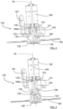
- Figure 4 and Figure 6 show the cutting disc 160 in a highest position, farthest to the ground surface 108, and corresponding to a maximum grass cutting height.
- the helical spring 130 runs between the retainer ring 131 and the second spring element holder 132 that is comprised in the connection portion 164.
- the retainer ring 131 rests on a flange part 166a of the hub 166 such that the helical spring 130, the retainer ring 131 and the second spring element holder 132 are adapted to rotate together with the hub 166.
- An annular seal 133 circumvents the transmission axle 169 to provide sealing, the annular seal being fitted in a collar part 135 that is comprised in the motor flange 167.
- the helical spring 130 is here in its most compressed state in a running position, the coupling protrusions 121, 122 engage the heels of the fifth pair of opposing engagement recesses 175a, 175b having the smallest depths along the common rotation axis Ax and are marked with "5" on the cutting disc 160. This brings the cutting disc 160 to a running position closest to the cutter propulsion unit 165.
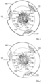
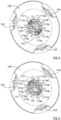
- the cutting disc can be rotated relative the knob 120, around the common rotation axis Ax, such that another pair of opposing recesses can be chosen for the coupling protrusions 121, 122, in this example the first pair of opposing engagement recesses 171a, 171b having the largest depth along the common rotation axis Ax and are marked with "1" on the cutting disc 160 are chosen.
- the spring force brings the coupling protrusions 121, 122 in engagement with the heels of the chosen first pair of opposing engagement recesses 171a, 171b which brings the cutting disc 160 to its lowest position, closest to the ground surface 108, and corresponding to a minimum grass cutting height.
- the helical spring 130 is here in its most expanded state, the coupling protrusions 121, 122 engage the first pair of opposing engagement recesses 171a, 171b which have the largest depth along the common rotation axis Ax.
- any one of the pair of opposing recesses can be chosen for the coupling protrusions 121, 122, conferring a corresponding grass cutting height by positioning the cutting disc 160 in a corresponding position along the common rotation axis Ax.
- a cover 126 can be used to seal an end of the aperture 161 that is adapted to face the ground surface 108 during operation of the lawn mower cutter unit 102, and this during operation of the robotic lawn mower 100. By means of the cover, undesired particles such as grass, debris, and dust are prevented from entering the aperture 161.
- the collar part 135 is adapted to not be in contact with the hub 166, in Figure 2 , Figure 4 and Figure 5 it is indicated that the collar part 166a comprises a step 166b (indicated in Figure 2 ) to avoid said contact.
- the present disclosure is not limited to the above, but may vary freely within the scope of the appended claims.
- the description above has been directed to a robotic lawn mower 100, the present disclosure is applicable for any type of lawn mower with at least one motor-powered cutting disc such as for example a robotic lawn mower, a hand-moved lawn mower with or without motor-powered wheels, as well as a riding mower.
- the knob may comprise more or less coupling protrusions. At least one coupling protrusion is adapted to engage a corresponding heel of a recess such that a grass cutting height is defined by the position of the cutting disc 160 along the common rotation axis Ax.
- connection portion 164 comprises at least two engagement recesses with mutually different depths long the common rotation axis Ax.
- the engagement recesses may be arranged pair-wise opposing each other with respect to the common rotation axis Ax, where two opposing engagement recesses have mutually equal depths along the common rotation axis Ax. In this case, there should be at least two pairs of opposing engagement recesses where the pairs have mutually different depths along the common rotation axis Ax.
- the hub 166 is press-fitted to the transmission axle 169.
- the hub 166 and the transmission axle 169 have a cylindrical shape and run along the common rotation axis Ax.
- the hub 166 may be at least partly hollow, allowing it to be thread over the transmission axle 169 and fitted tightly by means of press-fitting or other type of fitting.
- Other ways to secure the hub 166 to the transmission axle 169 are of course conceivable such as for example glue, welding, and/or fastening screws or pins. It is even conceivable that the hub 166 and the transmission axle 169 are formed as one and the same part.
- the hub 166 and the retainer ring 131 are formed as one and the same part.
- the retainer ring 131 is attached to the hub 166.
- the knob is attached to the hub by means of a screw 125, enabling an uncomplicated replacement if, for example, one or more coupling protrusions brakes.
- a screw may be comprised in the coupling interface 140.
- the cutting disc 160 should be displaceable along the common rotation axis Ax, against the spring force of the spring element 130, according to some aspects when displaced towards the cutter propulsion unit 165.
- the lawn mower cutter unit 102 comprises the coupling interface 140, the cover 126, the seal 133, the motor flange 167 and the cutter propulsion unit 165. According to some aspects, some details such as the cover 126 and the seal 133 are optional in the lawn mower cutter unit 102.
Landscapes
- Life Sciences & Earth Sciences (AREA)
- Environmental Sciences (AREA)
- Harvester Elements (AREA)
Abstract
Description
- The present disclosure relates to a powered lawn mower, for example a robotic lawn mower, where the cutting height can be easily adjusted by a user.
- Grass cutting machines are for used for both domestic and commercial applications and can be powered using an electric motor or an internal combustion engine. A so-called rotary cutter employs a cutting member which is rotatable in a plane substantially parallel to the ground and about an axis which is normal to the ground, where the cutting member comprises an arm or a disc that is rotatably supported in its center and has cutting edges arranged at its ends or its circumference.
- Automated or robotic power tools such as robotic lawn mowers are becoming increasingly more popular. In a typical deployment a work area, such as a garden, the work area is enclosed by a boundary wire with the purpose of keeping the robotic lawn mower inside the work area. An electric control signal may be transmitted through the boundary wire thereby generating an (electro-) magnetic field emanating from the boundary wire. The robotic working tool is typically arranged with one or more sensors adapted to sense the control signal.
- The robotic lawn mower can then cut grass on a user's lawn automatically and can be charged automatically without intervention of the user, and no longer needs to be manually managed after being set once. The robotic lawn mower typically comprises charging skids for contacting corresponding contact plates in a charging station when docking into the charging station for receiving a charging current through, and possibly also for transferring information by means of electrical communication between the charging station and the robotic lawn mower.
- Most conventional lawn mowers include some means for adjusting the grass cutting height since different users like to cut their lawns to different lengths, and to cut different areas of their lawns to different lengths. This can depend on grow rate of the grass and the cutting frequency of a particular area, as well as on general user desires regarding height of cut grass.
- Most lawn mowers includes means for providing an adjustable height of cutting height, for example wheels or rollers can be connected to a housing in a number of different positions, each position corresponding to a different height of cut, but requires a large number of components in order to adjust the height, and is thus expensive to manufacture.
- Cutting height adjustment can also be made by inserting or removing spacers between the cutter blade and the drive shaft to which the cutter blade is fastened. The adjustment involves unbolting the blade from the drive shaft, inserting or removing spacers, and bolting the blade back onto the drive shaft. This operation is relatively cumbersome and time consuming, and requires spacers to be stored.
-
EP 531071 EP 766911 -
EP 3935933 discloses a lawn mower comprising at least two engagement plateau arrangements which are connected to a cutting disc, mutually separated along a vertical extension and adapted to receive a coupling member comprised in the transmission axle. This enables the cutting disc to obtain a certain vertical position in dependence of which engagement plateau arrangement that has received the coupling member that is secured by means of screws. -
CN 103621244 discloses a mower with a cutterhead and a transmission part that is provided with a matching-connecting face which is connected with the cutterhead in a matched mode. The cutterhead is provided with a first installation face and a second installation face, one on each side of the cutter head, for abutting connection with the matching-connecting face. By turning the cutterhead around, a user can switch between two different cutting heights. - There is, however, a need to provide improved and alternative means for an uncomplicated change of grass cutting height of a lawn mower in a more versatile and efficient manner than previously presented, needing lesser parts and no special tools..
- The object of the present disclosure is to provide improved and alternative means for setting a grass cutting height of a lawn mower in a more versatile, uncomplicated and efficient manner than previously presented, needing lesser parts and no special tools.
- This object is achieved by means of a lawn mower cutter unit comprising a cutter propulsion unit with a transmission axle that is adapted to be rotated around a common rotation axis, a hub that is rotatably connected to the transmission axle, a cutting disc, and a knob. The knob is rotatably connected to the hub such that the knob is adapted to rotate with the hub and the transmission axle. The cutting disc is displaceable along the common rotation axis, against a spring force of a spring element. The cutting disc and the knob are comprised in a coupling interface that is comprised in the lawn mower cutter unit and adapted to transfer a rotational torque transferred from the hub to the cutting disc. The coupling interface is adapted to releasably lock the cutting disc in mutually separated positions along the common rotation axis by means of the spring force, conferring an associated certain grass cutting height for each locked position.
- This means that the grass cutting height can be adjusted by displacing the
cutting disc 160 along the common rotation axis Ax and locking thecutting disc 160 in a position that corresponds to a desired grass cutting height. - According to some aspects, the cutting disc comprises a connection portion that comprises an aperture and at least two engagement recesses which are formed in the aperture and extend to at last two mutually different depths parallel to the common rotation axis. The knob comprises at least one coupling protrusion that extends away from the common rotation axis and is adapted to transfer a rotational torque transferred from the hub to the cutting disc via a corresponding engagement recess. The recesses are adapted to receive said coupling protrusion in at least two different mounting positions along the common rotation axis. The mounting positions are locked by means of the spring force such that the cutting disc obtains a certain vertical position along the common rotation axis in dependence of which engagement recess that has received the corresponding coupling protrusion.
- This means that the grass cutting height can be adjusted by displacing the
cutting disc 160 along the common rotation axis Ax and locking thecutting disc 160 in a position that corresponds to a desired grass cutting height without the need of any tools. - According to some aspects, the lawn mower cutter unit further comprises a cover adapted to seal an end of the aperture that is adapted to face the ground surface during operation of the lawn mower cutter unit.
- By means of the cover, undesired particles such as grass, debris, and dust are prevented from entering the aperture.
- According to some aspects, the common rotation axis extends through a centre portion of the knob. This means that the knob has a symmetrical position with respect to the coupling interface.
- According to some aspects, the connection portion comprises at least two pairs of opposing engagement recesses, each pair of opposing engagement recesses having the same depth along the common rotation axis. According to some aspects, the knob comprises two opposing coupling protrusions which are adapted to engage a pair of opposing engagement recesses.
- This provides a secure transfer of rotational torque from the knob to the cutting disc via the coupling protrusions when engaging a pair of opposing engagement recesses.
- According to some aspects, the coupling interface comprises the spring element that is adapted to encompass the hub, the knob, the recesses, a first spring element holder and a second spring element holder.
- This means that the coupling interface comprises relatively few parts which leads to low productions cost and reliability.
- According to some aspects, the first spring element holder is a retainer ring that is adapted to rest against a motor flange comprised in the cutter propulsion unit and the second spring element holder is comprised in the connection portion. The spring element is in the form of a helical spring that is positioned between the spring element holders.
- This means that the spring element can exercise the spring force in a reliable and desired manner.
- According to some aspects, the coupling interface comprises a bushing that is adapted to be positioned in the connection portion and to circumvent the hub. The bushing stabilizes the hub.
- According to some aspects, the cutting disc is displaceable along the common rotation axis, against the spring force of the spring element, when displaced towards the cutter propulsion unit. This means that the spring force urges the cutting disc away from the cutter propulsion unit and enables an uncomplicated design and easily managed setting of grass cutting height
- This object is also achieved by means of lawn mowers and cutting discs that are associated with the above advantages.
- The present disclosure will now be described more in detail with reference to the appended drawings, where:
- Figure 1
- shows a schematic side view of a robotic lawn mower;
- Figure 2
- shows a first schematic exploded view of a lawn mower cutter unit comprised in a robotic lawn mower;
- Figure 3
- shows a second schematic exploded view of a lawn mower cutter unit comprised in a robotic lawn mower;
- Figure 4
- shows a schematic cut-open side view of the lawn mower cutter unit in a first locked position;
- Figure 5
- shows a schematic side cut-open view of the lawn mower cutter unit in a second locked position;
- Figure 6
- shows a schematic side bottom view of a cutting disc illustrating a first step for setting a grass cutting height;
- Figure 7
- shows a schematic bottom view of a cutting disc illustrating a second step for setting a grass cutting height;
- Figure 8
- shows a schematic side bottom view of a cutting disc illustrating a third step for setting a grass cutting height; and
- Figure 9
- shows a schematic side bottom view of a cutting disc illustrating a fourth step for setting a grass cutting height.
- Aspects of the present disclosure will now be described more fully hereinafter with reference to the accompanying drawings. The different devices, systems, computer programs and methods disclosed herein can, however, be realized in many different forms and should not be construed as being limited to the aspects set forth herein. Like numbers in the drawings refer to like elements throughout.
- The terminology used herein is for describing aspects of the disclosure only and is not intended to limit the invention. As used herein, the singular forms "a", "an" and "the" are intended to include the plural forms as well, unless the context clearly indicates otherwise.
- It should be noted that even though the description given herein will be focused on robotic lawn mowers, the teachings herein may also be applied to any type of lawn mower with a rotary cutter.
-
Figure 1 schematically illustrates alawnmower 100 according to some embodiments of the present disclosure. According to the illustrated embodiments, thelawnmower 100 is a self-propelled autonomousrobotic lawnmower 100 capable of navigating and cutting grass in an autonomous manner in an area without the intervention or the control of a user. This can be enabled by means of one or more environmental detection sensors such as Lidar, radar and/or ultrasonic sensors, as well as boundary wire sensors adapted to sense boundary wire control signals. Additionally, or alternatively, navigation devices such as GPS (Global Positioning System) devices can also be used. -
Figure 1 shows a schematic side view of arobotic lawn mower 100 that is adapted for a forward travelling direction D, has abody 105 and a plurality ofwheels robotic lawn mower 100 has fourwheels rear wheels 106 and twofront wheels 107 whichwheels flat ground surface 108. - The
robotic lawn mower 100 comprises acontrol unit 110 and a firstelectrical motor 150 that is adapted to provide motive power and/or steering of therobotic lawn mower 100. In this example, therear wheels 106 are powered and constitute drive wheels, and steering may be achieved by rotating therear wheels 106 in different directions. Wheels that are not powered, here thefront wheels 106, constitute support wheels which can be in the form of pivotable castor wheels that follow the travel direction D. - According to further embodiments, the
robotic lawn mower 100 may be provided with another number of wheels, such as three wheels. Moreover, according to further embodiments, therobotic lawn mower 100 may be provided with another configuration of driven and non-driven wheels, such as a front wheel drive or an all-wheel drive. - According to the illustrated embodiments, the
control unit 110 may be configured to control propulsion of therobotic lawn mower 100, and steer therobotic lawn mower 100, by controlling thedrive wheels 106 of therobotic lawn mower 100. - It should be noted that even if the description herein is focused on electric motors, combustion engines may alternatively be used in combination with an electric motor arrangement.
- The
robotic lawn mower 100 comprises chargingskids 156 for contacting contact plates of a charging station (not shown) when docking into the charging station for receiving a charging current, and possibly also for transferring information by means of electrical communication between the charging station and therobotic lawn mower 100. - The
robotic lawn mower 100 also comprises at least one rechargeable electric power source such as abattery 155 for providing power to theelectric motor arrangement 150. Thebattery 155 is arranged to be charged by means of received charging current from the charging station, received through the charging skids 156 or other suitable charging connectors. - As shown in
Figure 2 - Figure 5 , therobotic lawn mower 100 also comprises a lawnmower cutter unit 102 that comprises agrass cutting device 160 and acutter motor 165, or more generally, acutter propulsion unit 165, that also is powered by thebattery 155 or, alternatively, by a separate power source. Thecutter propulsion unit 165 is adapted to drive thecutter propulsion unit 165 and comprises atransmission axle 169 that is adapted to be rotated around a common rotation axis Ax. - In this example, as shown in
Figure 6 - Figure 9 , thegrass cutting device 160 is constituted by acutting disc 160 that according to some aspects comprises a plurality of cutting edges such as cuttingknifes knife - With reference also to
Figure 2 - Figure 5 , the lawnmower cutter unit 102 comprises ahub 166 that is rotatably connected to thetransmission axle 169, aknob 120 that is rotatably connected to thehub 166 such that theknob 120 is adapted to rotate with thehub 166 and thetransmission axle 169. - According to the present disclosure, the
cutting disc 160 is displaceable along the common rotation axis Ax, against a spring force of aspring element 130. Thecutting disc 160 and theknob 120 are comprised in acoupling interface 140 that is adapted to transfer a rotational torque transferred from thehub 166 to thecutting disc 160. Thecoupling interface 140 is adapted to releasably lock thecutting disc 160 in mutually separated positions along the common rotation axis Ax by means of the spring force, conferring an associated certain grass cutting height for each locked position. Thecoupling interface 140 is comprised in the lawnmower cutter unit 102. - This means that the grass cutting height can be adjusted by displacing the
cutting disc 160 along the common rotation axis Ax and locking thecutting disc 160 in a positioned that corresponds to a desired grass cutting height. - According to some aspects, the
cutting disc 160 comprises aconnection portion 164 that comprises anaperture 161 and at least twoengagement recesses aperture 161 and extend to at last two mutually different depths parallel to the common rotation axis Ax. Theknob 120 comprises at least onecoupling protrusion hub 166 to thecutting disc 160 via acorresponding engagement recess recesses cutting disc 160 obtains a certain vertical position along the common rotation axis Ax in dependence of whichengagement recess coupling protrusion - This means that the grass cutting height can be adjusted by displacing the
cutting disc 160 along the common rotation axis Ax and locking thecutting disc 160 in a positioned that corresponds to a desired grass cutting height without the need of any tools. - According to some aspects, the
cutting disc 160 is displaceable along the common rotation axis Ax, against the spring force of thespring element 130, when displaced towards thecutter propulsion unit 165. This means that the spring force urges the cutting disc away from thecutter propulsion unit 165 and enables an uncomplicated design and easily managed setting of grass cutting height. This is the case for the example illustrated inFigure 2-9 . - It is also conceivable that the
cutting disc 160 is displaceable along the common rotation axis Ax, against a spring force of a spring element, when displaced away from thecutter propulsion unit 165, for example pulled towards a user, when adjusting the grass cutting height. In that case, thecoupling interface 140 has to be designed accordingly, for example the recesses will have to run in an opposite direction along the common rotation axis Ax. The details of such a design are not described here, but can of course easily be implemented by the skilled person. - According to some aspects, the
connection portion 164 comprises at least two pairs of opposingengagement recesses engagement recesses recess corresponding heel corresponding heel Figure 9 for reasons of clarity). - In the example illustrated in
Figure 2 - Figure 9 , theconnection portion 164 comprises five pairs of opposingengagement recesses cutting disc 160, and, according to some further aspects, theknob 120 comprises two opposingcoupling protrusions engagement recesses engagement recesses engagement recesses engagement recesses engagement recesses engagement recesses engagement recesses engagement recesses - This provides a secure transfer of rotational torque from the
knob 120 to thecutting disc 160 via thecoupling protrusions engagement recesses - According to some aspects, the
knob 120 is accessible from a bottom side S1 of therobotic lawn mower 100, which bottom side S1 faces aground surface 108 during operation of therobotic lawn mower 100. - This means that the knob is easily accessible when the grass cutting height is to be adjusted.
- According to some aspects, the
coupling interface 140 comprises thespring element 130 that is adapted to encompass thehub 166. Thecoupling interface 140 further comprises theknob 120, therecesses spring element holder 131 and a secondspring element holder 132. - This means that the
coupling interface 140 comprises relatively few parts which leads to low productions cost and reliability. - According to some aspects, the common rotation axis Ax extends through a centre portion of the
knob 120. This means that theknob 120 has a symmetrical position with respect to thecoupling interface 140. - According to some aspects, the
cutter propulsion unit 165 is mounted in amotor flange 167 which holds thecutter propulsion unit 165 in a fixed position. According to some further aspects, the firstspring element holder 131 is a retainer ring that is adapted to rest against amotor flange 167 and the secondspring element holder 132 is comprised in theconnection portion 164, where thespring element 130 is in the form of a helical spring that is positioned between thespring element holders spring element 130 can exercise the spring force in a reliable and desired manner. - According to some aspects, the second
spring element holder 132 is a separate part that is fitted into theconnection portion 164. - According to some aspects, the
coupling interface 140 comprises abushing 134 that is adapted to be positioned in theconnection portion 164 and to circumvent thehub 166. Thehub 166 runs within thebushing 134 that stabilizes thehub 166. According to some aspects, thebushing 134 is either a separate part or integral with theconnection portion 164. - In accordance with some aspects, an example of the working of the
coupling interface 140 will now be described more in detail.Figure 4 andFigure 6 show thecutting disc 160 in a highest position, farthest to theground surface 108, and corresponding to a maximum grass cutting height. Thehelical spring 130 runs between theretainer ring 131 and the secondspring element holder 132 that is comprised in theconnection portion 164. - The
retainer ring 131 rests on aflange part 166a of thehub 166 such that thehelical spring 130, theretainer ring 131 and the secondspring element holder 132 are adapted to rotate together with thehub 166. Anannular seal 133 circumvents thetransmission axle 169 to provide sealing, the annular seal being fitted in acollar part 135 that is comprised in themotor flange 167. Thehelical spring 130 is here in its most compressed state in a running position, thecoupling protrusions engagement recesses cutting disc 160. This brings thecutting disc 160 to a running position closest to thecutter propulsion unit 165. - In
Figure 7 , thecutting disc 160 is pressed towards thecutter propulsion unit 165, against the spring force, such that thecoupling protrusions engagement recesses helical spring 130 is compressed a little bit more than its most compressed state in a running position, and thecutting disc 160 is brought even closer to thecutter propulsion unit 165. - Now, as illustrated in
Figure 8 , the cutting disc can be rotated relative theknob 120, around the common rotation axis Ax, such that another pair of opposing recesses can be chosen for thecoupling protrusions engagement recesses cutting disc 160 are chosen. - As illustrated in
Figure 5 andFigure 9 , when thecutting disc 160 is released, the spring force brings thecoupling protrusions engagement recesses cutting disc 160 to its lowest position, closest to theground surface 108, and corresponding to a minimum grass cutting height. Thehelical spring 130 is here in its most expanded state, thecoupling protrusions engagement recesses - In this manner, any one of the pair of opposing recesses can be chosen for the
coupling protrusions cutting disc 160 in a corresponding position along the common rotation axis Ax. - When the
cutting disc 160 is properly positioned, acover 126 can be used to seal an end of theaperture 161 that is adapted to face theground surface 108 during operation of the lawnmower cutter unit 102, and this during operation of therobotic lawn mower 100. By means of the cover, undesired particles such as grass, debris, and dust are prevented from entering theaperture 161. - The
collar part 135 is adapted to not be in contact with thehub 166, inFigure 2 ,Figure 4 and Figure 5 it is indicated that thecollar part 166a comprises astep 166b (indicated inFigure 2 ) to avoid said contact. - The present disclosure is not limited to the above, but may vary freely within the scope of the appended claims. For example, although the description above has been directed to a
robotic lawn mower 100, the present disclosure is applicable for any type of lawn mower with at least one motor-powered cutting disc such as for example a robotic lawn mower, a hand-moved lawn mower with or without motor-powered wheels, as well as a riding mower. - Although two coupling protrusions are shown in the example, the knob may comprise more or less coupling protrusions. At least one coupling protrusion is adapted to engage a corresponding heel of a recess such that a grass cutting height is defined by the position of the
cutting disc 160 along the common rotation axis Ax. - The
connection portion 164 comprises at least two engagement recesses with mutually different depths long the common rotation axis Ax. As described previously, the engagement recesses may be arranged pair-wise opposing each other with respect to the common rotation axis Ax, where two opposing engagement recesses have mutually equal depths along the common rotation axis Ax. In this case, there should be at least two pairs of opposing engagement recesses where the pairs have mutually different depths along the common rotation axis Ax. - According to some aspects, the
hub 166 is press-fitted to thetransmission axle 169. According to some aspects, thehub 166 and thetransmission axle 169 have a cylindrical shape and run along the common rotation axis Ax. Thehub 166 may be at least partly hollow, allowing it to be thread over thetransmission axle 169 and fitted tightly by means of press-fitting or other type of fitting. Other ways to secure thehub 166 to thetransmission axle 169 are of course conceivable such as for example glue, welding, and/or fastening screws or pins. It is even conceivable that thehub 166 and thetransmission axle 169 are formed as one and the same part. According to some aspects, thehub 166 and theretainer ring 131 are formed as one and the same part. According to some further aspects, theretainer ring 131 is attached to thehub 166. - According to some aspects, the knob is attached to the hub by means of a
screw 125, enabling an uncomplicated replacement if, for example, one or more coupling protrusions brakes. Such a screw may be comprised in thecoupling interface 140. - Other types of springs elements are conceivable, the
cutting disc 160 should be displaceable along the common rotation axis Ax, against the spring force of thespring element 130, according to some aspects when displaced towards thecutter propulsion unit 165. - According to some aspects, the lawn
mower cutter unit 102 comprises thecoupling interface 140, thecover 126, theseal 133, themotor flange 167 and thecutter propulsion unit 165. According to some aspects, some details such as thecover 126 and theseal 133 are optional in the lawnmower cutter unit 102.
Claims (13)
- A lawn mower cutter unit (102) comprising a cutter propulsion unit (165) with a transmission axle (169) that is adapted to be rotated around a common rotation axis (Ax), a hub (166) that is rotatably connected to the transmission axle (169), a cutting disc (160), and a knob (120) that is rotatably connected to the hub (166) such that the knob (120) is adapted to rotate with the hub (166) and the transmission axle (169), wherein the cutting disc (160) is displaceable along the common rotation axis (Ax), against a spring force of a spring element (130), where the cutting disc (160) and the knob (120) are comprised in a coupling interface (140) that is comprised in the lawn mower cutter unit (102) and adapted to transfer a rotational torque transferred from the hub (166) to the cutting disc (160), the coupling interface (140) being adapted to releasably lock the cutting disc (160) in mutually separated positions along the common rotation axis (Ax) by means of the spring force, conferring an associated certain grass cutting height for each locked position.
- The lawn mower cutter unit (102) according to claim 1, wherein the cutting disc (160) comprises a connection portion (164) that comprises an aperture (161) and at least two engagement recesses (171a, 171b; 172a, 172b; 173a, 173b; 174a, 174b; 175a, 175b) which are formed in the aperture (161) and extend to at last two mutually different depths parallel to the common rotation axis (Ax), and where the knob (120) comprises at least one coupling protrusion (121, 122) that extends away from the common rotation axis (Ax) and is adapted to transfer a rotational torque transferred from the hub (166) to the cutting disc (160) via a corresponding engagement recess (171a, 171b; 172a, 172b; 173a, 173b; 174a, 174b; 175a, 175b), the recesses (171a, 171b; 172a, 172b; 173a, 173b; 174a, 174b; 175a, 175b) being adapted to receive said coupling protrusion (121,122) in at least two different mounting positions along the common rotation axis (Ax), where the mounting positions are locked by means of the spring force such that the cutting disc (160) obtains a certain vertical position along the common rotation axis (Ax) in dependence of which engagement recess (171a, 171b; 172a, 172b; 173a, 173b; 174a, 174b; 175a, 175b) that has received the corresponding coupling protrusion (121, 122).
- The lawn mower cutter unit (102) according to claim 2, further comprising a cover (126) adapted to seal an end of the aperture (161) that is adapted to face the ground surface (108) during operation of the lawn mower cutter unit (102).
- The lawn mower cutter unit (102) according to any one of the previous claims, wherein the common rotation axis (Ax) extends through a centre portion of the knob (120).
- The lawn mower cutter unit (102) according to any one of the previous claims, wherein the connection portion (164) comprises at least two pairs of opposing engagement recesses (171a, 171b; 172a, 172b; 173a, 173b; 174a, 174b; 175a, 175b), each pair of opposing engagement recesses (171a, 171b; 172a, 172b; 173a, 173b; 174a, 174b; 175a, 175b) having the same depth along the common rotation axis (Ax).
- The lawn mower cutter unit (102) according to claim 5, wherein the knob (120) comprises two opposing coupling protrusions (121, 122) which are adapted to engage a pair of opposing engagement recesses (171a, 171b; 172a, 172b; 173a, 173b; 174a, 174b; 175a, 175b).
- The lawn mower cutter unit (102) according to any one of the previous claims, wherein the coupling interface (140) comprises- the spring element (130) that is adapted to encompass the hub (166),- the knob (120),- the recesses (171a, 171b; 172a, 172b; 173a, 173b; 174a, 174b; 175a, 175b),- a first spring element holder (131) and- a second spring element holder (132).
- The lawn mower cutter unit (102) according to claim 7, wherein the first spring element holder (131) is a retainer ring that is adapted to rest against a motor flange (167) comprised in the cutter propulsion unit (165) and the second spring element holder (132) is comprised in the connection portion (164), where the spring element (130) is in the form of a helical spring that is positioned between the spring element holders (131 132).
- The lawn mower cutter unit (102) according to any one of the previous claims, wherein the coupling interface (140) comprises a bushing (134) that is adapted to be positioned in the connection portion (164) and to circumvent the hub (166).
- The lawn mower cutter unit (102) according to any one of the previous claims, wherein the cutting disc (160) is displaceable along the common rotation axis (Ax), against the spring force of the spring element (130), when displaced towards the cutter propulsion unit (165).
- A lawn mower (100) comprising the lawn mower cutter unit (102) according to any one of the claims 1-10.
- The lawn mower (100) according to claim 11, wherein the knob (120) is accessible from a bottom side (S1) of the lawn mower (100), which bottom side (S1) faces a ground surface (108) during operation of the lawn mower (100).
- A cutting disc (160) adapted to be mounted to a lawn mower (100), wherein the cutting disc (160) comprises a connection portion (164) that comprises an aperture (161) and at least two engagement recesses (171a, 171b; 172a, 172b; 173a, 173b; 174a, 174b; 175a, 175b) which are formed in the aperture (161) and extend to at last two mutually different depths parallel to the common rotation axis (Ax), where the depth of each recess (171a, 171b; 172a, 172b; 173a, 173b; 174a, 174b; 175a, 175b) is limited by a corresponding heel (176, 177, 178).
Applications Claiming Priority (1)
| Application Number | Priority Date | Filing Date | Title |
|---|---|---|---|
| SE2250532A SE545637C2 (en) | 2022-05-02 | 2022-05-02 | Means for adjusting cutting height of a powered lawn mower |
Publications (2)
| Publication Number | Publication Date |
|---|---|
| EP4272536A1 true EP4272536A1 (en) | 2023-11-08 |
| EP4272536B1 EP4272536B1 (en) | 2024-04-17 |
Family
ID=84982204
Family Applications (1)
| Application Number | Title | Priority Date | Filing Date |
|---|---|---|---|
| EP23152253.3A Active EP4272536B1 (en) | 2022-05-02 | 2023-01-18 | Means for adjusting cutting height of a powered lawn mower |
Country Status (4)
| Country | Link |
|---|---|
| US (1) | US20230345870A1 (en) |
| EP (1) | EP4272536B1 (en) |
| CN (1) | CN116982467B (en) |
| SE (1) | SE545637C2 (en) |
Families Citing this family (2)
| Publication number | Priority date | Publication date | Assignee | Title |
|---|---|---|---|---|
| EP4149237B1 (en) * | 2020-05-14 | 2026-02-11 | Globe (Jiangsu) Co., Ltd. | A battery pack assembly for a robotic mower |
| US20230380342A1 (en) * | 2022-05-25 | 2023-11-30 | Techtronic Cordless Gp | Robotic garden tool with blade height adjustment |
Citations (8)
| Publication number | Priority date | Publication date | Assignee | Title |
|---|---|---|---|---|
| EP0531071A1 (en) | 1991-08-30 | 1993-03-10 | Electrolux Outdoor Products Limited | Improvements in and relating to grass cutting machines |
| EP0766911A1 (en) | 1995-10-03 | 1997-04-09 | Electrolux Outdoor Products Limited | Cutting-height adjustment for lawnmower |
| CN103621244A (en) | 2012-08-28 | 2014-03-12 | 苏州宝时得电动工具有限公司 | Hay mower |
| WO2017051663A1 (en) * | 2015-09-24 | 2017-03-30 | 日立工機株式会社 | Self-propelled grass mower |
| CN112470678A (en) * | 2020-12-21 | 2021-03-12 | 格力博(江苏)股份有限公司 | Grass cutter |
| US20210084815A1 (en) * | 2019-09-23 | 2021-03-25 | Globe (Jiangsu) Co., Ltd | Mower |
| EP3935933A1 (en) | 2020-07-06 | 2022-01-12 | Husqvarna Ab | Means for adjusting cutting height of a powered lawn mower |
| SE2051268A1 (en) * | 2020-11-02 | 2022-05-03 | Husqvarna Ab | Lawnmower cutting assembly and lawnmower |
Family Cites Families (10)
| Publication number | Priority date | Publication date | Assignee | Title |
|---|---|---|---|---|
| US6971223B2 (en) * | 2001-01-25 | 2005-12-06 | Electrolux Home Products, Inc. | Wheeled trimmer device of adjustable height |
| CN202738448U (en) * | 2012-08-15 | 2013-02-20 | 浙江天宸智能科技有限公司 | Intelligent grass cutter capable of precisely adjusting tool carrier |
| CN204443108U (en) * | 2015-01-15 | 2015-07-08 | 杭州菲沃机器人科技有限公司 | For the cutterhead elevating mechanism of hand-push type mower |
| CN204707495U (en) * | 2015-04-27 | 2015-10-21 | 苏州宝时得电动工具有限公司 | mower |
| CN214545686U (en) * | 2020-09-09 | 2021-11-02 | 宁波奇亚园林工具有限公司 | Intelligence lawn mower lift adjustment mechanism |
| CN112119745B (en) * | 2020-10-16 | 2025-06-24 | 格力博(江苏)股份有限公司 | A lawn mower |
| CN112119748B (en) * | 2020-10-16 | 2025-10-24 | 格力博(江苏)股份有限公司 | Lawn mower |
| CN215011656U (en) * | 2020-11-04 | 2021-12-07 | 苏州宝时得电动工具有限公司 | Grass cutter |
| CN214508007U (en) * | 2021-04-06 | 2021-10-29 | 深圳市来语飞智能科技有限公司 | Manual cutting system height adjusting device of automatic mower |
| CN113615379B (en) * | 2021-09-02 | 2023-01-06 | 浙江亚特电器有限公司 | Quick installation system for lawn machine blade and lawn machine |
-
2022
- 2022-05-02 SE SE2250532A patent/SE545637C2/en unknown
-
2023
- 2023-01-18 EP EP23152253.3A patent/EP4272536B1/en active Active
- 2023-02-23 CN CN202310162153.5A patent/CN116982467B/en active Active
- 2023-05-02 US US18/142,235 patent/US20230345870A1/en active Pending
Patent Citations (8)
| Publication number | Priority date | Publication date | Assignee | Title |
|---|---|---|---|---|
| EP0531071A1 (en) | 1991-08-30 | 1993-03-10 | Electrolux Outdoor Products Limited | Improvements in and relating to grass cutting machines |
| EP0766911A1 (en) | 1995-10-03 | 1997-04-09 | Electrolux Outdoor Products Limited | Cutting-height adjustment for lawnmower |
| CN103621244A (en) | 2012-08-28 | 2014-03-12 | 苏州宝时得电动工具有限公司 | Hay mower |
| WO2017051663A1 (en) * | 2015-09-24 | 2017-03-30 | 日立工機株式会社 | Self-propelled grass mower |
| US20210084815A1 (en) * | 2019-09-23 | 2021-03-25 | Globe (Jiangsu) Co., Ltd | Mower |
| EP3935933A1 (en) | 2020-07-06 | 2022-01-12 | Husqvarna Ab | Means for adjusting cutting height of a powered lawn mower |
| SE2051268A1 (en) * | 2020-11-02 | 2022-05-03 | Husqvarna Ab | Lawnmower cutting assembly and lawnmower |
| CN112470678A (en) * | 2020-12-21 | 2021-03-12 | 格力博(江苏)股份有限公司 | Grass cutter |
Also Published As
| Publication number | Publication date |
|---|---|
| US20230345870A1 (en) | 2023-11-02 |
| CN116982467B (en) | 2026-03-10 |
| SE2250532A1 (en) | 2023-11-03 |
| CN116982467A (en) | 2023-11-03 |
| SE545637C2 (en) | 2023-11-21 |
| EP4272536B1 (en) | 2024-04-17 |
Similar Documents
| Publication | Publication Date | Title |
|---|---|---|
| EP4272536B1 (en) | Means for adjusting cutting height of a powered lawn mower | |
| US4642976A (en) | Lawn mower trimmer and edger attachment | |
| CN105979767A (en) | The claimed invention concerns a plate spring adapted to hold a tool, a tool, a tool holder, a robotic work tool and a robotic working tool system | |
| CN112423579A (en) | Robot mower cutting device, robot mower, cutting blade and method | |
| US20230231436A1 (en) | Electric Motor and Blade Assembly for a Lawn Mower | |
| KR20130092450A (en) | Lawn mower | |
| US20230240180A1 (en) | Robotic garden tool with manual blade height adjustment and movable blade guard | |
| EP3935933B1 (en) | Means for adjusting cutting height of a powered lawn mower | |
| AU2020273288A1 (en) | Walk-behind mower with steering wheel control | |
| US11751505B2 (en) | Lawnmower blade disc and maintenance position thereof | |
| US5010717A (en) | Oscillating-type mowing apparatus | |
| US11503768B2 (en) | Lawn mower having a maintenance tool for maintaining a cutting blade | |
| US20230276733A1 (en) | Robotic garden tool with quick change mechanism | |
| EP4440290A1 (en) | Lawnmower cutting arrangement and lawnmower | |
| EP0997066B1 (en) | A blade-whetting apparatus for bladed wheels | |
| US20240349642A1 (en) | Multi-segmented lawn mower cutting blade and lawn mower including same | |
| CN221082055U (en) | Mower | |
| JPH073868Y2 (en) | Cutting blade clutch structure in lawn mower | |
| CN219068922U (en) | Lithium battery mower | |
| JPH02219513A (en) | Lawn mower | |
| CN211793026U (en) | Grass cutter | |
| JP2020110098A (en) | Weeding device and weeding rotor | |
| JPH057030U (en) | Walk-behind lawn mower |
Legal Events
| Date | Code | Title | Description |
|---|---|---|---|
| PUAI | Public reference made under article 153(3) epc to a published international application that has entered the european phase |
Free format text: ORIGINAL CODE: 0009012 |
|
| STAA | Information on the status of an ep patent application or granted ep patent |
Free format text: STATUS: REQUEST FOR EXAMINATION WAS MADE |
|
| 17P | Request for examination filed |
Effective date: 20230118 |
|
| AK | Designated contracting states |
Kind code of ref document: A1 Designated state(s): AL AT BE BG CH CY CZ DE DK EE ES FI FR GB GR HR HU IE IS IT LI LT LU LV MC ME MK MT NL NO PL PT RO RS SE SI SK SM TR |
|
| GRAP | Despatch of communication of intention to grant a patent |
Free format text: ORIGINAL CODE: EPIDOSNIGR1 |
|
| STAA | Information on the status of an ep patent application or granted ep patent |
Free format text: STATUS: GRANT OF PATENT IS INTENDED |
|
| RIC1 | Information provided on ipc code assigned before grant |
Ipc: A01D 34/74 20060101AFI20240125BHEP |
|
| INTG | Intention to grant announced |
Effective date: 20240209 |
|
| GRAS | Grant fee paid |
Free format text: ORIGINAL CODE: EPIDOSNIGR3 |
|
| GRAA | (expected) grant |
Free format text: ORIGINAL CODE: 0009210 |
|
| STAA | Information on the status of an ep patent application or granted ep patent |
Free format text: STATUS: THE PATENT HAS BEEN GRANTED |
|
| P01 | Opt-out of the competence of the unified patent court (upc) registered |
Effective date: 20240216 |
|
| AK | Designated contracting states |
Kind code of ref document: B1 Designated state(s): AL AT BE BG CH CY CZ DE DK EE ES FI FR GB GR HR HU IE IS IT LI LT LU LV MC ME MK MT NL NO PL PT RO RS SE SI SK SM TR |
|
| REG | Reference to a national code |
Ref country code: GB Ref legal event code: FG4D |
|
| REG | Reference to a national code |
Ref country code: CH Ref legal event code: EP |
|
| REG | Reference to a national code |
Ref country code: IE Ref legal event code: FG4D Ref country code: DE Ref legal event code: R096 Ref document number: 602023000049 Country of ref document: DE |
|
| REG | Reference to a national code |
Ref country code: LT Ref legal event code: MG9D |
|
| REG | Reference to a national code |
Ref country code: NL Ref legal event code: MP Effective date: 20240417 |
|
| REG | Reference to a national code |
Ref country code: AT Ref legal event code: MK05 Ref document number: 1676242 Country of ref document: AT Kind code of ref document: T Effective date: 20240417 |
|
| PG25 | Lapsed in a contracting state [announced via postgrant information from national office to epo] |
Ref country code: NL Free format text: LAPSE BECAUSE OF FAILURE TO SUBMIT A TRANSLATION OF THE DESCRIPTION OR TO PAY THE FEE WITHIN THE PRESCRIBED TIME-LIMIT Effective date: 20240417 |
|
| PG25 | Lapsed in a contracting state [announced via postgrant information from national office to epo] |
Ref country code: NL Free format text: LAPSE BECAUSE OF FAILURE TO SUBMIT A TRANSLATION OF THE DESCRIPTION OR TO PAY THE FEE WITHIN THE PRESCRIBED TIME-LIMIT Effective date: 20240417 |
|
| PG25 | Lapsed in a contracting state [announced via postgrant information from national office to epo] |
Ref country code: IS Free format text: LAPSE BECAUSE OF FAILURE TO SUBMIT A TRANSLATION OF THE DESCRIPTION OR TO PAY THE FEE WITHIN THE PRESCRIBED TIME-LIMIT Effective date: 20240817 |
|
| PG25 | Lapsed in a contracting state [announced via postgrant information from national office to epo] |
Ref country code: BG Free format text: LAPSE BECAUSE OF FAILURE TO SUBMIT A TRANSLATION OF THE DESCRIPTION OR TO PAY THE FEE WITHIN THE PRESCRIBED TIME-LIMIT Effective date: 20240417 |
|
| PG25 | Lapsed in a contracting state [announced via postgrant information from national office to epo] |
Ref country code: HR Free format text: LAPSE BECAUSE OF FAILURE TO SUBMIT A TRANSLATION OF THE DESCRIPTION OR TO PAY THE FEE WITHIN THE PRESCRIBED TIME-LIMIT Effective date: 20240417 Ref country code: FI Free format text: LAPSE BECAUSE OF FAILURE TO SUBMIT A TRANSLATION OF THE DESCRIPTION OR TO PAY THE FEE WITHIN THE PRESCRIBED TIME-LIMIT Effective date: 20240417 |
|
| PG25 | Lapsed in a contracting state [announced via postgrant information from national office to epo] |
Ref country code: GR Free format text: LAPSE BECAUSE OF FAILURE TO SUBMIT A TRANSLATION OF THE DESCRIPTION OR TO PAY THE FEE WITHIN THE PRESCRIBED TIME-LIMIT Effective date: 20240718 |
|
| PG25 | Lapsed in a contracting state [announced via postgrant information from national office to epo] |
Ref country code: PT Free format text: LAPSE BECAUSE OF FAILURE TO SUBMIT A TRANSLATION OF THE DESCRIPTION OR TO PAY THE FEE WITHIN THE PRESCRIBED TIME-LIMIT Effective date: 20240819 |
|
| PG25 | Lapsed in a contracting state [announced via postgrant information from national office to epo] |
Ref country code: ES Free format text: LAPSE BECAUSE OF FAILURE TO SUBMIT A TRANSLATION OF THE DESCRIPTION OR TO PAY THE FEE WITHIN THE PRESCRIBED TIME-LIMIT Effective date: 20240417 |
|
| PG25 | Lapsed in a contracting state [announced via postgrant information from national office to epo] |
Ref country code: AT Free format text: LAPSE BECAUSE OF FAILURE TO SUBMIT A TRANSLATION OF THE DESCRIPTION OR TO PAY THE FEE WITHIN THE PRESCRIBED TIME-LIMIT Effective date: 20240417 |
|
| PG25 | Lapsed in a contracting state [announced via postgrant information from national office to epo] |
Ref country code: PL Free format text: LAPSE BECAUSE OF FAILURE TO SUBMIT A TRANSLATION OF THE DESCRIPTION OR TO PAY THE FEE WITHIN THE PRESCRIBED TIME-LIMIT Effective date: 20240417 |
|
| PG25 | Lapsed in a contracting state [announced via postgrant information from national office to epo] |
Ref country code: LV Free format text: LAPSE BECAUSE OF FAILURE TO SUBMIT A TRANSLATION OF THE DESCRIPTION OR TO PAY THE FEE WITHIN THE PRESCRIBED TIME-LIMIT Effective date: 20240417 |
|
| PG25 | Lapsed in a contracting state [announced via postgrant information from national office to epo] |
Ref country code: PT Free format text: LAPSE BECAUSE OF FAILURE TO SUBMIT A TRANSLATION OF THE DESCRIPTION OR TO PAY THE FEE WITHIN THE PRESCRIBED TIME-LIMIT Effective date: 20240819 Ref country code: PL Free format text: LAPSE BECAUSE OF FAILURE TO SUBMIT A TRANSLATION OF THE DESCRIPTION OR TO PAY THE FEE WITHIN THE PRESCRIBED TIME-LIMIT Effective date: 20240417 Ref country code: NO Free format text: LAPSE BECAUSE OF FAILURE TO SUBMIT A TRANSLATION OF THE DESCRIPTION OR TO PAY THE FEE WITHIN THE PRESCRIBED TIME-LIMIT Effective date: 20240717 Ref country code: LV Free format text: LAPSE BECAUSE OF FAILURE TO SUBMIT A TRANSLATION OF THE DESCRIPTION OR TO PAY THE FEE WITHIN THE PRESCRIBED TIME-LIMIT Effective date: 20240417 Ref country code: IS Free format text: LAPSE BECAUSE OF FAILURE TO SUBMIT A TRANSLATION OF THE DESCRIPTION OR TO PAY THE FEE WITHIN THE PRESCRIBED TIME-LIMIT Effective date: 20240817 Ref country code: HR Free format text: LAPSE BECAUSE OF FAILURE TO SUBMIT A TRANSLATION OF THE DESCRIPTION OR TO PAY THE FEE WITHIN THE PRESCRIBED TIME-LIMIT Effective date: 20240417 Ref country code: GR Free format text: LAPSE BECAUSE OF FAILURE TO SUBMIT A TRANSLATION OF THE DESCRIPTION OR TO PAY THE FEE WITHIN THE PRESCRIBED TIME-LIMIT Effective date: 20240718 Ref country code: FI Free format text: LAPSE BECAUSE OF FAILURE TO SUBMIT A TRANSLATION OF THE DESCRIPTION OR TO PAY THE FEE WITHIN THE PRESCRIBED TIME-LIMIT Effective date: 20240417 Ref country code: ES Free format text: LAPSE BECAUSE OF FAILURE TO SUBMIT A TRANSLATION OF THE DESCRIPTION OR TO PAY THE FEE WITHIN THE PRESCRIBED TIME-LIMIT Effective date: 20240417 Ref country code: BG Free format text: LAPSE BECAUSE OF FAILURE TO SUBMIT A TRANSLATION OF THE DESCRIPTION OR TO PAY THE FEE WITHIN THE PRESCRIBED TIME-LIMIT Effective date: 20240417 Ref country code: AT Free format text: LAPSE BECAUSE OF FAILURE TO SUBMIT A TRANSLATION OF THE DESCRIPTION OR TO PAY THE FEE WITHIN THE PRESCRIBED TIME-LIMIT Effective date: 20240417 Ref country code: RS Free format text: LAPSE BECAUSE OF FAILURE TO SUBMIT A TRANSLATION OF THE DESCRIPTION OR TO PAY THE FEE WITHIN THE PRESCRIBED TIME-LIMIT Effective date: 20240717 |
|
| PG25 | Lapsed in a contracting state [announced via postgrant information from national office to epo] |
Ref country code: DK Free format text: LAPSE BECAUSE OF FAILURE TO SUBMIT A TRANSLATION OF THE DESCRIPTION OR TO PAY THE FEE WITHIN THE PRESCRIBED TIME-LIMIT Effective date: 20240417 |
|
| REG | Reference to a national code |
Ref country code: DE Ref legal event code: R097 Ref document number: 602023000049 Country of ref document: DE |
|
| PG25 | Lapsed in a contracting state [announced via postgrant information from national office to epo] |
Ref country code: EE Free format text: LAPSE BECAUSE OF FAILURE TO SUBMIT A TRANSLATION OF THE DESCRIPTION OR TO PAY THE FEE WITHIN THE PRESCRIBED TIME-LIMIT Effective date: 20240417 |
|
| PG25 | Lapsed in a contracting state [announced via postgrant information from national office to epo] |
Ref country code: CZ Free format text: LAPSE BECAUSE OF FAILURE TO SUBMIT A TRANSLATION OF THE DESCRIPTION OR TO PAY THE FEE WITHIN THE PRESCRIBED TIME-LIMIT Effective date: 20240417 |
|
| PG25 | Lapsed in a contracting state [announced via postgrant information from national office to epo] |
Ref country code: RO Free format text: LAPSE BECAUSE OF FAILURE TO SUBMIT A TRANSLATION OF THE DESCRIPTION OR TO PAY THE FEE WITHIN THE PRESCRIBED TIME-LIMIT Effective date: 20240417 Ref country code: SK Free format text: LAPSE BECAUSE OF FAILURE TO SUBMIT A TRANSLATION OF THE DESCRIPTION OR TO PAY THE FEE WITHIN THE PRESCRIBED TIME-LIMIT Effective date: 20240417 |
|
| PG25 | Lapsed in a contracting state [announced via postgrant information from national office to epo] |
Ref country code: SM Free format text: LAPSE BECAUSE OF FAILURE TO SUBMIT A TRANSLATION OF THE DESCRIPTION OR TO PAY THE FEE WITHIN THE PRESCRIBED TIME-LIMIT Effective date: 20240417 |
|
| PG25 | Lapsed in a contracting state [announced via postgrant information from national office to epo] |
Ref country code: SM Free format text: LAPSE BECAUSE OF FAILURE TO SUBMIT A TRANSLATION OF THE DESCRIPTION OR TO PAY THE FEE WITHIN THE PRESCRIBED TIME-LIMIT Effective date: 20240417 Ref country code: SK Free format text: LAPSE BECAUSE OF FAILURE TO SUBMIT A TRANSLATION OF THE DESCRIPTION OR TO PAY THE FEE WITHIN THE PRESCRIBED TIME-LIMIT Effective date: 20240417 Ref country code: RO Free format text: LAPSE BECAUSE OF FAILURE TO SUBMIT A TRANSLATION OF THE DESCRIPTION OR TO PAY THE FEE WITHIN THE PRESCRIBED TIME-LIMIT Effective date: 20240417 Ref country code: EE Free format text: LAPSE BECAUSE OF FAILURE TO SUBMIT A TRANSLATION OF THE DESCRIPTION OR TO PAY THE FEE WITHIN THE PRESCRIBED TIME-LIMIT Effective date: 20240417 Ref country code: DK Free format text: LAPSE BECAUSE OF FAILURE TO SUBMIT A TRANSLATION OF THE DESCRIPTION OR TO PAY THE FEE WITHIN THE PRESCRIBED TIME-LIMIT Effective date: 20240417 Ref country code: CZ Free format text: LAPSE BECAUSE OF FAILURE TO SUBMIT A TRANSLATION OF THE DESCRIPTION OR TO PAY THE FEE WITHIN THE PRESCRIBED TIME-LIMIT Effective date: 20240417 |
|
| PG25 | Lapsed in a contracting state [announced via postgrant information from national office to epo] |
Ref country code: IT Free format text: LAPSE BECAUSE OF FAILURE TO SUBMIT A TRANSLATION OF THE DESCRIPTION OR TO PAY THE FEE WITHIN THE PRESCRIBED TIME-LIMIT Effective date: 20240417 |
|
| PLBE | No opposition filed within time limit |
Free format text: ORIGINAL CODE: 0009261 |
|
| STAA | Information on the status of an ep patent application or granted ep patent |
Free format text: STATUS: NO OPPOSITION FILED WITHIN TIME LIMIT |
|
| 26N | No opposition filed |
Effective date: 20250120 |
|
| PG25 | Lapsed in a contracting state [announced via postgrant information from national office to epo] |
Ref country code: SI Free format text: LAPSE BECAUSE OF FAILURE TO SUBMIT A TRANSLATION OF THE DESCRIPTION OR TO PAY THE FEE WITHIN THE PRESCRIBED TIME-LIMIT Effective date: 20240417 |
|
| PG25 | Lapsed in a contracting state [announced via postgrant information from national office to epo] |
Ref country code: SE Free format text: LAPSE BECAUSE OF FAILURE TO SUBMIT A TRANSLATION OF THE DESCRIPTION OR TO PAY THE FEE WITHIN THE PRESCRIBED TIME-LIMIT Effective date: 20240417 |
|
| PG25 | Lapsed in a contracting state [announced via postgrant information from national office to epo] |
Ref country code: LU Free format text: LAPSE BECAUSE OF NON-PAYMENT OF DUE FEES Effective date: 20250118 Ref country code: MC Free format text: LAPSE BECAUSE OF FAILURE TO SUBMIT A TRANSLATION OF THE DESCRIPTION OR TO PAY THE FEE WITHIN THE PRESCRIBED TIME-LIMIT Effective date: 20240417 |
|
| PG25 | Lapsed in a contracting state [announced via postgrant information from national office to epo] |
Ref country code: BE Free format text: LAPSE BECAUSE OF NON-PAYMENT OF DUE FEES Effective date: 20250131 |
|
| REG | Reference to a national code |
Ref country code: BE Ref legal event code: MM Effective date: 20250131 |
|
| PGFP | Annual fee paid to national office [announced via postgrant information from national office to epo] |
Ref country code: FR Payment date: 20251210 Year of fee payment: 4 |
|
| PG25 | Lapsed in a contracting state [announced via postgrant information from national office to epo] |
Ref country code: IE Free format text: LAPSE BECAUSE OF NON-PAYMENT OF DUE FEES Effective date: 20250118 |
|
| PGFP | Annual fee paid to national office [announced via postgrant information from national office to epo] |
Ref country code: DE Payment date: 20251209 Year of fee payment: 4 |