EP4271137A1 - Led driver, luminaire, method for operating a led driver and system comprising a plurality of led drivers - Google Patents
Led driver, luminaire, method for operating a led driver and system comprising a plurality of led drivers Download PDFInfo
- Publication number
- EP4271137A1 EP4271137A1 EP22170919.9A EP22170919A EP4271137A1 EP 4271137 A1 EP4271137 A1 EP 4271137A1 EP 22170919 A EP22170919 A EP 22170919A EP 4271137 A1 EP4271137 A1 EP 4271137A1
- Authority
- EP
- European Patent Office
- Prior art keywords
- led driver
- data
- led
- time
- driver
- Prior art date
- Legal status (The legal status is an assumption and is not a legal conclusion. Google has not performed a legal analysis and makes no representation as to the accuracy of the status listed.)
- Pending
Links
- 238000000034 method Methods 0.000 title claims abstract description 17
- 238000013500 data storage Methods 0.000 claims abstract description 80
- 238000012545 processing Methods 0.000 claims description 35
- 238000004891 communication Methods 0.000 claims description 18
- 238000012544 monitoring process Methods 0.000 claims description 4
- 230000008859 change Effects 0.000 description 6
- 230000008569 process Effects 0.000 description 6
- 230000004044 response Effects 0.000 description 6
- 238000010586 diagram Methods 0.000 description 4
- 230000001419 dependent effect Effects 0.000 description 2
- 230000002159 abnormal effect Effects 0.000 description 1
- 238000012937 correction Methods 0.000 description 1
- 230000003247 decreasing effect Effects 0.000 description 1
- 238000001514 detection method Methods 0.000 description 1
- 125000000524 functional group Chemical group 0.000 description 1
- 238000002513 implantation Methods 0.000 description 1
- 230000007257 malfunction Effects 0.000 description 1
- 238000005259 measurement Methods 0.000 description 1
- 230000001960 triggered effect Effects 0.000 description 1
Images


Classifications
-
- H—ELECTRICITY
- H05—ELECTRIC TECHNIQUES NOT OTHERWISE PROVIDED FOR
- H05B—ELECTRIC HEATING; ELECTRIC LIGHT SOURCES NOT OTHERWISE PROVIDED FOR; CIRCUIT ARRANGEMENTS FOR ELECTRIC LIGHT SOURCES, IN GENERAL
- H05B45/00—Circuit arrangements for operating light-emitting diodes [LED]
- H05B45/50—Circuit arrangements for operating light-emitting diodes [LED] responsive to malfunctions or undesirable behaviour of LEDs; responsive to LED life; Protective circuits
Definitions
- the present invention relates to a light emitting diode driver (LED driver), a luminaire comprising such a LED driver and a LED light source, a method for operating a LED driver and a system comprising a plurality of LED drivers.
- LED driver light emitting diode driver
- a LED driver is a device used for driving a LED light source, such as at least one LED or a LED module comprising at least one LED.
- the LED driver is configured to electrically supply the LED light source enabling the LED light source to emit light.
- the LED driver may control the light emission of the LED light source via the electrical supply of the LED light source. For example, by decreasing an electrical power supplied to the LED light source the LED driver may decrease light intensity of the light emission (i.e. the LED driver may perform dimming) and vice versa.
- an LED driver During the operation of an LED driver several events may occur, which may disturb or interrupt operation of the LED driver (and light emission of a LED light source being driven by the LED driver). Such events may even damage the LED driver. Such events may comprise a short-circuit of the LED light source when being driven by the LED driver, sudden voltage and/or current spikes provided to the LED driver and/or in the LED driver etc.
- a light emitting diode driver (LED driver) is provided.
- the LED driver comprises a data storage for sequentially storing data of an operation of the LED driver according to a circular buffer.
- the LED driver is configured to continuously monitor and store the data of the operation of the LED driver sequentially in the data storage. Further, the LED driver is configured to secure, in case a trigger occurs, at least part of the data stored in the data storage at a point in time at which the trigger occurred and corresponding to a time period before the point in time from being overwritten.
- the present invention proposes continuously monitoring data of an operation of a LED driver and sequentially storing the continuously monitored data in a data storage of the LED driver according to a circular buffer.
- a trigger occurs, the data that are stored in the data storage at a point in time of the trigger and that correspond to a time period before the point in time of the trigger may be secured from being overwritten.
- This allows searching for the reasons of an event that may occur during the operation of the LED driver. Namely, as soon as such an event is detected the trigger may be caused and, thus, the aforementioned data of the data storage that are stored in the data storage when the trigger occurred and, thus, the event occurred may be secured from being overwritten.
- these data comprise the data of the operation of the LED driver that were continuously monitored during the time period before the point in time of the trigger, they may be used for analyzing what conditions or type of data of the operation of the LED driver lead to the event that caused the trigger. This information may then be used for pre-detecting that the event will occur before the event actually occurs by analyzing the continuously monitored data of the operation of the LED driver, e.g. comparing the monitored data with the secured data that lead to the event. This allows preventing the event from occurring again in the future by allowing the LED driver or another entity, e.g. a central processing unit (may be a central control unit or a control center) or a person, to perform counter measurements.
- a central processing unit may be a central control unit or a control center
- a person may perform counter measurements.
- the data storage is configured to sequentially store the continuously monitored data according to a circular buffer.
- the data storage reaches its maximum capacity (i.e. there is no empty storage space) when sequentially storing the continuously monitored data, the data storage overwrites the already stored data beginning with the oldest data stored in the data storage (i.e. beginning with the data stored for the longest time period in the data storage). Therefore, the continuously stored data is stored in the data storage for a certain time period, wherein this time period depends on the total capacity of the data storage and the speed of continuously monitoring and storing the data sequentially in the data storage. This is acceptable as long as no trigger (e.g.
- the data storage still allows an analysis of data that were monitored in the past with regard to the point in time of the trigger.
- Storing the data corresponding to a time period allows analyzing a time course of the data, i.e. how the data changed over time.
- voltage data corresponding to a time period allow analyzing a time course of the voltage data during the time period, i.e. analyzing a time course of the voltage indicated or represented by the voltage data.
- the LED driver allows an error analysis and search for the reasons of an event occurring during the operation of the LED driver (e.g. conditions that lead to the event) and, thus, is advantageous for reducing or preventing events that are not desired from occurring during the operation of the LED driver.
- the LED driver allows determining what event (e.g. what kind of event) occurred during the operation of the LED driver that caused the trigger.
- the data of the operation of the LED driver are data measured and/or obtained during the operation of the LED driver.
- the data of the operation of the LED driver may be or may comprise parameters or values of the operation of the LED driver that are measured and/or obtained during the operation of the LED driver.
- the LED driver may be configured to continuously monitor the data of the operation of the LED driver by continuously measuring and/or obtaining the data.
- the passage "the LED driver is configured to continuously monitor and store the data of the operation of the LED driver sequentially in the data storage” may mean that the LED driver is configured to continuously monitor the data of the operation of the LED driver and to sequentially store the continuously monitored data in the data storage.
- data that is monitored at a point in time are also stored at the point in time (optionally with a negligible time delay that may be caused by the process of storing) in the data storage.
- the data storage may be referred to as circular buffer storage.
- the term "ring buffer” may be used as a synonym for the term "circular buffer”.
- the data storage is configured to work like a circular buffer, i.e. perform the function of a circular buffer for sequentially storing the continuously monitored data. That is, the data storage may be configured to sequentially store data and start sequentially overwriting the data starting with the oldest or longest stored data when the data storage is full (i.e. there is no empty storage space).
- the time period before the point in time may be directly before the point in time.
- the time period may be adjacent to the point in time laying before the point in time.
- the term "adjacent" may be understood as "directly adjacent”.
- the time period before the point in time may end with the point in time at which the trigger occurred.
- the time period may comprise the point in time, at which the trigger occurred. That is, the data corresponding to the time period before the point in time at which the trigger occurred may comprise the data corresponding to the point in time at which the trigger occurred.
- time or "time point” may be used as a synonym for the term "point in time”.
- first time period The time period before the point in time at which the trigger occurred
- first point in time The point in time at which the trigger occurred
- first point in time The point in time at which the trigger occurred
- first point in time The point in time at which the trigger occurred
- the passage "point in time of the trigger” may be used as a synonym for the passage "point in time at which the trigger occurred”.
- the LED driver may be configured to secure, in case the trigger occurs, the data (i.e. all the data) stored in the data storage at the point in time at which the trigger occurred and corresponding to the time period before the point in time from being overwritten.
- the data corresponding to the time period before the point in time at which the trigger occurred are the data of the operation of the LED driver that were continuously monitored during said time period.
- the data corresponding to the point in time at which the trigger occurred are the data of the operation of the LED driver that were monitored at the point in time.
- the LED driver is configured to additionally secure, in case the trigger occurs, at least part of the data stored in the data storage at a second point in time after the point in time at which the trigger occurred and corresponding to a second time period after the point in time from being overwritten.
- the LED driver may be configured to secure, in case the trigger occurs, at least part of the data stored in the data storage at the first point in time at which the trigger occurred and corresponding to the first time period before the first point in time as well as of the data stored in the data storage at the second point in time after the first point in time and corresponding to the second time period after the first point in time from being overwritten.
- the second time period after the first point in time may be directly after the first point in time.
- the second time period may be adjacent to the first point in time laying after the first point in time.
- the term "adjacent" may be understood as "directly adjacent”.
- the second time period after the first point in time may start with the first point in time (i.e. with the point in time at which the trigger occurred).
- the second time period after the first point in time may end with the second point in time.
- the second time period may comprise the point in time, at which the trigger occurred.
- the second time period may be referred to as "time period after the point in time at which the trigger occurred”.
- the LED driver may be configured to secure, in case the trigger occurs, the data (i.e. all the data) stored in the data storage at the second point in time and corresponding to the second time period after the first point in time from being overwritten.
- the data corresponding to the second time period are the data of the operation of the LED driver that were continuously monitored during the second time period.
- the LED driver may be configured to secure the respective data from being overwritten by storing the respective data in a second data storage of the LED driver.
- the LED driver may be configured to secure the respective data from being overwritten by providing the respective data to outside the LED driver.
- the LED driver may be configured to secure the respective data from being overwritten by providing the respective data to at least one other LED driver and/or a central processing unit (e.g. a control center).
- the respective data may be the data stored in the data storage at the first point in time at which the trigger occurred and corresponding to the time period before the first point in time or at least part of the aforementioned data.
- the respective data may be the data stored in the data storage at the first point in time at which the trigger occurred and corresponding to the time period before the first point in time as well as the data stored in the data storage at the second point in time after the first point in time and corresponding to the second time period after the first point in time or at least part of the aforementioned data.
- the second data storage may be configured to store the respective data without overwriting data.
- the second data storage may be configured to sequentially store the respective data without overwriting data.
- the second data storage may be configured to delete data when controlled to do so (e.g. by the LED driver itself or from outside the LED driver, such as from a person or a central control unit/control center).
- the LED driver may be configured to perform a wireless and/or wired communication with one or more entities outside the LED driver, such as at least one other LED driver and/or a central processing unit (e.g. a control center), for providing the respective data to outside the LED driver.
- a central processing unit e.g. a control center
- the LED driver may be configured to be electrically connected via a bus system (e.g. a wired bus) with the at least one other LED driver and/or a central processing unit.
- a bus system e.g. a wired bus
- the LED driver may be configured to cause the trigger at one or more other LED drivers each being a LED driver according to the first aspect, in case the trigger occurs at the LED driver.
- the one or more other LED drivers may be neighboring LED drivers of the LED driver.
- the LED driver and the one or more other LED drivers may be grouped in a group (e.g. functional group).
- the LED driver is configured to obtain information on an event, which caused the trigger, by processing the secured data.
- the LED driver is configured to determine what event caused the trigger (e.g. what kind of event) by processing the secured data.
- the LED driver may be configured to search for or determine the reasons of an event that caused the trigger (e.g. conditions that lead to the event).
- the LED driver may be configured to process the secured data.
- the LED driver may be configured to pre-detect or predict occurrence of the event in the future by analyzing the continuously monitored data using the obtained information and/or the secured data.
- the LED driver may be configured to pre-detect or predict occurrence of the event in the future by comparing the continuously monitored data with the secured data (that were secured due to the trigger caused by the event).
- the LED driver may analyze data of a supply voltage (e.g. mains voltage) of the LED driver of the secured data and thereby detect a sudden voltage spike or rise of voltage over a threshold. Due to this detection, the LED driver may determine or come to the conclusion that the event of an over voltage at a LED light source when driven by the LED driver, which caused the trigger, is caused by the sudden voltage spike or rise of voltage over the threshold.
- a supply voltage e.g. mains voltage
- the LED driver may be configured to provide, in response to a request from outside, e.g. from at least one other LED driver, a central processing unit (e.g. a control center) and/or a person (e.g. user), a result of processing or analyzing the secured data to outside the LED driver, e.g. to the at least one other LED driver, the central processing unit (e.g. a control center) and/or the person (e.g. user).
- a central processing unit e.g. a control center
- a person e.g. user
- the LED driver is configured to receive data of an operation of at least one other LED driver corresponding to a respective time period, during which the secured data have been continuously monitored by the LED driver, from outside the LED driver.
- the LED driver may be configured to receive the data of the operation of the at least one other LED driver corresponding to the respective time period, during which the secured data have been continuously monitored by the LED driver, from the at least one other LED and/or a central processing unit (e.g. a control center).
- a central processing unit e.g. a control center
- the respective time period may comprise or be the first time period optionally comprising the first point in time.
- the respective time period may comprise or be the first time period and the second time period.
- the respective time period may optionally comprise the first point in time and/or the second point in time.
- the LED driver is configured to obtain information on an event, which caused the trigger, by processing the secured data and the received data.
- the LED driver is configured to determine what event caused the trigger (e.g. what kind of event) by processing the secured data and the received data.
- the LED driver may be configured to search for or determine the reasons of an event that caused the trigger (e.g. conditions that lead to the event).
- the LED driver may be configured to process the secured data and received data (e.g. correlate the secured data and received data).
- the LED driver may be configured to pre-detect or predict occurrence of the event in the future by analyzing the continuously monitored data using the obtained information and/or the secured data and received data (e.g. correlating the secured data and received data).
- the LED driver may be configured to pre-detect or predict occurrence of the event in the future by comparing the continuously monitored data with the secured data (that were secured due to the trigger caused by the event) and the received data.
- the LED driver may be configured to combine or correlate the secured data and the received data for determining the reasons of the event (e.g. conditions that lead to the event) and/or what event caused the trigger (i.e. what kind of event).
- the LED driver may be configured to pre-detect or predict occurrence of the event in the future by analyzing the continuously monitored data using a correlation of the secured data and the received data.
- the LED driver may be configured to provide, in response to a request from outside, e.g. from at least one other LED driver, a central processing unit (e.g. a control center) and/or a person (e.g. user), a result of processing or analyzing the secured data and received data to outside the LED driver, e.g. to the at least one other LED driver, the central processing unit (e.g. a control center) and/or the person (e.g. user).
- a central processing unit e.g. a control center
- a person e.g. user
- the data of the operation of the LED driver may comprise at least one of the following: one or more electrical parameters input to the respective LED driver, one or more electrical parameters output by the respective LED driver, one or more external commands received by the receptive LED driver, communication data of communication means of the respective LED driver, and one or more internal operation parameters of the respective LED driver.
- the term “respective LED driver” may correspond or be the LED driver according to the first aspect or the aforementioned at least one other LED driver.
- the one or more electrical parameters input to the respective LED driver may comprise or may be an input voltage and/or input current.
- the one or more electrical parameters output by the respective LED driver may comprise or may be an output voltage and/or output current.
- the one or more external commands received by the receptive LED driver may comprise or may be a dimming command.
- the one or more internal operation parameters of the respective LED driver may comprise or may be a frequency of a feed-back control, one or more internal commands, a temperature inside the LED driver, a frequency behavior of an internal driver stage, an error of a feedback control of an internal driver stage, an operation mode of the respective LED driver and/or an operation frequency of the respective LED driver.
- the input voltage and the input current may be mains voltage and mains current, respectively, input to the LED driver or provided to the input of the LED driver.
- the input voltage and the input current may be the voltage and current, respectively, with which the LED driver is electrically supplied from an external energy source, such as an AC source (e.g. mains) and/or DC source (e.g. a battery or a supply bus).
- an AC source e.g. mains
- DC source e.g. a battery or a supply bus
- the one or more electrical parameters input to the respective LED driver may comprise or may be an input power (electrical power).
- the LED driver may provide the output voltage and/or output current to a LED light source when the LED driver drives the LED light source (e.g. the LED light source is electrically connected to an output of the LED driver for being driven and, thus, electrically supplied by the LED Driver).
- the output voltage and the output current may be referred to as LED voltage and LED current, respectively.
- the one or more electrical parameters output by the respective LED driver may comprise or may be an output power (electrical power).
- the one or more external commands may be DALI and/or DALI-2 commands, i.e. commands according to the DALI and/or DALI-2 standard.
- DALI Digital Adressable Lighting Interface
- DALI-2 also referred to as DALI Edition 2 being the follow-up standard of DALI
- the external commands may be commands of any other known standard, such as the ZigBee standard etc.
- the LED driver may comprise communication means for receiving the external commands.
- the communication means may be or may be referred to as communication circuit, communication module or communication interface.
- the communication means may be configured to communicate wirelessly and/or wired (via a data bus) with one or more entities (e.g.
- the one or more external commands may comprise or may be, for example, a light color change command, a command for setting an operation mode of the LED driver, a command for setting an electrical parameter, e.g. an output voltage, output current and/or output power, a command for setting an operation frequency of the LED driver and/or any other command(s) known in the field of lighting.
- the communication data of communication means of the respective LED driver may comprise or may be data communicated by the communication means and/or data used for communicating by the communication means.
- the communication means of the respective LED driver may be as outlined above.
- the one or more internal operation parameters of the respective LED driver may comprise or may be
- Physical parameters measured inside the respective LED driver may comprise or may be, for example, a temperature inside the respective LED driver.
- the respective LED driver may comprise one or more LED driver stages forming an electrical supply circuit electrically connected between an input of the respective LED driver and an output of the respective LED driver.
- a LED light source may be electrically connected to the output of the respective LED driver for being driven and, thus, electrically supplied by the respective LED driver, in particular the electrical supply circuit of the respective LED driver.
- the one or more LED driver stages may comprise or may be at least one actively switched power converter, such as at least one actively switched AC/DC converter and/or at least one actively switched DC/DC converter. Examples of actively switched converters comprise boost converters, buck converters, flyback converters, resonant converters etc.
- the electrical supply circuit of the respective LED driver may comprise filter means (e.g. an EMI filter), rectification means (e.g.
- the active PFC means may be implemented by an LED driver stage of the one or more LED driver stages comprising at least one actively switched power converter.
- the electrical supply circuit of the respective LED driver e.g. the one or more driver stages, may comprise any other one or more electrical components known in the art for implementing an LED driver, e.g. an electrical supply function of an LED driver.
- physical parameters measured inside the respective LED driver may comprise or may be, for example, a voltage, current and/or power of at least one of the aforementioned electrical components, such as the at least one driver stage (e.g. a voltage across an inductor of an actively switched power converter, a current through the inductor etc.); a frequency behavior of at least one driver stage; and/or any other physical parameter(s9, such as electrical parameter(s), that may be measured or obtained in a LED driver.
- the at least one driver stage e.g. a voltage across an inductor of an actively switched power converter, a current through the inductor etc.
- any other physical parameter(s9, such as electrical parameter(s) that may be measured or obtained in a LED driver.
- the one or more settings of the respective LED driver during the operation of the respective LED driver may comprise or may be, for example, an operation mode of the respective LED driver, operation frequency of the respective LED driver, maximum allowable output voltage, output current and/or output power and/or any other known setting(s) of a LED driver.
- An operation mode of the respective LED driver may comprise, for example, an emergency operation mode and a normal operation mode, in case the LED driver is an emergency LED driver for emergency lighting.
- the operation mode of the respective LED driver may comprise, for example, a mode for controlling switching of an actively switched power converter, such as a continuous conduction mode (CCM), discontinuous conduction mode (DCM) and borderline conduction mode.
- CCM continuous conduction mode
- DCM discontinuous conduction mode
- the operation mode of the respective LED driver may, additionally or alternatively, comprise or be any other operation mode(s) known for operating a LED driver.
- the respective LED driver may comprise control means for controlling components of the respective LED driver (e.g. communication means and/or electrical supply circuit of the respective LED driver).
- the control means may comprise or be a controller, microcontroller, processor, microprocessor, application-specific integrated circuit (ASIC), field-programmable gate array (FPGA) and/or any other known control means type(s).
- the control means may be configured to analyze and/or process the data of the operation of the respective LED driver. Therefore, the control means may be referred to as control and processing means.
- the at least one parameter, at least one value and/or information resulting out of a control (e.g. a feedback control) and/or computation performed by the respective LED driver during the operation of the respective LED drive may comprise or be, for example, an error of a feedback control performable by the control means of the respective LED driver and/or a frequency behavior of a driver stage of the electrical supply circuit due to the control of the driver stage by the control means.
- the data of the operation of the respective LED driver may comprise or may be physical parameters, such as electrical parameters, that are
- Physical parameters measured at the LED driver may be for example a temperature, light condition, humidity, electromagnetic pollution etc. of an environment of the LED driver.
- the data of the operation of the respective LED driver may comprise or may be at least one parameter, at least one value and/or information received and/or transmitted by the LED driver during the operation of the LED driver, wherein the at least one parameter, at least one value and/or information may impact the operation of the LED driver and/or may be caused by the operation of the LED driver.
- the data of the operation of the respective LED driver may comprise or may be one or more settings of the LED driver during the operation of the respective LED driver, wherein the one or more settings may change during the operation of the respective LED driver.
- the data of the operation of the respective LED driver may comprise or may be at least one parameter, at least one value and/or information resulting out of a control (e.g. a feedback control) and/or computation performed by the respective LED driver during the operation of the respective LED driver.
- a control e.g. a feedback control
- the LED driver is configured to receive the trigger from outside the LED driver.
- the LED driver is configured to receive the trigger from at least one other LED driver and/or a central processing unit (e.g. a control center).
- the LED driver is configured to receive the trigger from a person (e.g. a user).
- the LED driver may be configured to provide the secured data to outside, e.g. to at least one other LED driver, a central processing unit (e.g. a control center) and/or a person (e.g. user), in response to a request received from outside (e.g. from the at least one other LED driver, the central processing unit (e.g. the control center) and/or the person (e.g. user)).
- a central processing unit e.g. a control center
- a person e.g. user
- the trigger occurs when an event during the operation of the LED driver irrespective of the data is detected.
- the event may be a short-circuit of an LED light source when the LED light source is driven by the LED driver.
- the event may be, for example, at least one of the following: a disturbance of the external energy supply electrically supplying the LED driver, failure or malfunction of one or more components of the LED driver, an improper operation or use of the LED driver outside the operation boundaries for the LED driver, a sudden change of output power of a LED light source when the LED driver drives the LED light source, etc.
- the LED driver is configured to detect the event during the operation of the LED driver irrespective of the data.
- the LED driver may be configured to receive from outside the LED driver information that the event during the operation of the LED driver irrespective of the data is detected.
- the LED driver may be configured to receive from at least one other LED driver and/or a central processing unit (e.g. a control center) the information that the event during the operation of the LED driver irrespective of the data is detected.
- the trigger occurs when an event in the data stored in the data storage irrespective of the operation of the LED driver is detected.
- the event may be a voltage spike in input voltage data stored in the data storage.
- the event may be, for example, at least one of the following: a current spike in current data (e.g. input current data), a sudden change in an operation frequency of frequency data, sudden change in temperature data etc.
- the event may be a sudden change of one or more different data of the data, an abnormal pattern of one or more different data of the data and/or one or more different data of the data reaching a certain value or threshold.
- the LED driver is configured to detect the event in the data stored in the data storage irrespective of the operation of the LED driver by analyzing the data stored in the data storage.
- the above description of the LED driver according to the first aspect may be valid for the above mentioned at least one further LED driver.
- the aforementioned processing unit central processing unit
- a luminaire comprises a LED driver according to the first aspect of the invention, as described above, and a LED light source.
- the LED driver is configured to electrically supply the LED light source.
- the LED light source may be at least one light emitting diode (LED) and/or a LED module comprising at least one LED. Any known LEDs may be used for implementing the LED light source (e.g. organic LEDs, inorganic LEDs etc.).
- the passage “outside the LED driver” may mean “outside the luminaire”.
- the processing unit (central processing unit) outside the LED driver described in the description of the LED driver of the first aspect may be or may be part of control means of the luminaire.
- the luminaire according to the second aspect of the invention achieves the same advantages as the LED driver according to the first aspect of the invention.
- a method for operating a LED driver comprises continuously monitoring and storing data of an operation of the LED driver sequentially in a data storage according to a circular buffer. Further the method comprises, in case a trigger occurs, securing at least part of the data stored in the data storage at a point in time at which the trigger occurred and corresponding to a time period before the point in time from being overwritten.
- the method according to the third aspect of the invention achieves the same advantages as the LED driver according to the first aspect of the invention.
- a system comprising a plurality of LED drivers according to the first aspect of the invention, as described above.
- At least one LED driver of the plurality of LED drivers is configured to provide, in case the trigger occurs at the LED driver, the secured data to a control center and/or at least one other LED driver of the plurality of LED drivers.
- at least two LED drivers of the plurality of LED drivers are configured to provide, in case the trigger occurs at one or more of the at least two LED drivers, the respective secured data to a control center and/or the respective other LED driver of the at least two LED drivers.
- the at least one LED driver may be configured to communicate with the at least one other LED driver wirelessly and/or wired.
- the at least two LED drivers may be configured to communicate with each other wirelessly and/or wired.
- the at least two LED drivers may be configured to communicate with the control center wirelessly and/or wired.
- the plurality of LED drivers may be configured to communicate with each other and/or the control center via a wireless and/or wired communication.
- the control center may be part of the system.
- the plurality of LED drivers may be electrically connected via a bus system (e.g. a wired bus) with each other.
- the plurality of LED drivers and the control center may optionally be electrically connected via a bus system (e.g. a wired bus) with each other.
- control center is configured to determine what event caused the trigger at the at least one LED driver from which the control center received the secured data (e.g. what kind of event) by processing the received secured data.
- the control center may be configured to search for or determine the reasons of an event (e.g. conditions that lead to the event), which caused the trigger at the at least one LED driver from which the control center received the secured data.
- the control center may be configured to process the received secured data.
- the control center may be configured to provide the result of processing the received secured data to the at least one LED driver and optionally to one or more other LED drivers of the plurality of LED drivers.
- the control center may be configured to determine, in case the control center received the secured data from the at least two LED drivers, what event caused the trigger at one or more of the at least two LED drivers (e.g. what kind of event) by processing the secured data received from the at least two LED drivers (e.g. correlate the secured data received from the at least two LED drivers with each other).
- the control center may be configured to search for or determine, in case the control center received the secured data from the at least two LED drivers, the reasons of an event (e.g. conditions that lead to the event), which caused the trigger at one or more of the at least two LED drivers.
- the control center may be configured to process the secured data received from the at least two LED drivers (e.g. correlate the secured data received from the at least two LED drivers with each other).
- the control center may be configured to provide the result of processing the received secured data to the at least two LED drivers and optionally to one or more other LED drivers of the plurality of LED drivers.
- the at least one LED driver may be configured to provide the secured data to the control center and/or at least one other LED driver in response to a request received from outside the at least one LED driver, e.g. from the control center and/or a person (e.g. user).
- the at least two LED drivers may be configured to provide the respective secured data to the control center and/or the respective other LED driver of the at least two LED drivers in response to a request received from outside the at least one LED driver, e.g. from the control center and/or a person (e.g. user).
- One or more of the plurality of LED drivers may be configured to provide the secured data to outside, e.g. to the control center and/or to a person (e.g. user), in response to a request received from outside, e.g. from the control center and/or the person (e.g. user).
- the system according to the fourth aspect of the invention may be a luminaire.
- the description of the system of the fourth aspect may be correspondingly valid for the LED driver according to the first aspect of the invention.
- the system according to the fourth aspect of the invention achieves the same advantages as the LED driver according to the first aspect of the invention.
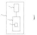
- FIG. 1 schematically shows a block diagram of an example of a LED driver according to an embodiment of the invention.
- the LED driver of Figure 1 is an example of the LED driver according to the first aspect of the invention.
- the description of the LED driver according to the first aspect is correspondingly valid for the LED driver of Figure 1 .
- the LED driver 1 of Figure 1 comprises a data storage 2 for sequentially storing, according to a circular buffer, data of an operation of the LED driver 1.
- the LED driver 1 is configured to continuously monitor and store the data of the operation of the LED driver 1 sequentially in the data storage 2. Further, the LED driver 1 is configured to secure, in case a trigger occurs, at least part of the data stored in the data storage 2 at a point in time at which the trigger occurred and corresponding to a time period before the point in time from being overwritten.
- the LED driver 1 is configured to additionally secure, in case the trigger occurs, at least part of the data stored in the data storage 2 at a second point in time after the point in time at which the trigger occurred and corresponding to a second time period after the point in time from being overwritten.
- a LED light source 3 may be electrically connected to the LED driver 1 (in particular to an output of the LED driver 1) for being driven and, thus, electrically supplied by the LED driver 1.
- the LED light source 3 may be at least one light emitting diode (LED) and/or a LED module comprising at least one LED. Any known LEDs may be used for implementing the LED light source 3(e.g. organic LEDs, inorganic LEDs etc.).
- the LED driver 1 and the LED light source 3 may form or be part of a luminaire 4.
- the luminaire 4 of Figure 1 may be an example of the luminaire according to the second aspect of the invention.
- the description of the luminaire according to the second aspect is correspondingly valid for the luminaire 4 of Figure 1 .
- Figures 2 to 4 schematically show an example of a state of a data storage of the LED driver of Figure 1 for three different points in time.
- the LED driver 1 may secure at least part of the data D1 stored in the data storage 2 at the point in time T1 and corresponding to a time period P1 before the point in time T1 from being overwritten.
- the time period P1 is directly before the point in time T1. That is, the time period P1 ends at the point in time T1. This may be differently, that is the time period P1 does not need to be directly before the point in time T1.
- the time period P1 may comprise the point in time T1, at which the trigger occurred. That is, the data D1 corresponding to the time period P1 before the point in time T1 at which the trigger occurred may comprise the data D2 corresponding to the point in time T1.
- the LED driver 1 stores the data monitored by the LED driver at the point in time T1.
- the data storage 2 is full (no empty storage space available)
- the oldest data stored in the data storage 2 are overwritten by current data (which are in the case of Figure 2 the data D2 monitored at the point in time T1).
- the direction of sequentially storing or writing and, thus, potentially overwriting previously stored data is indicated in Figure 2 by an arrow in counter-clockwise direction.
- the data D2 at the point in time T1 is the newest data stored in the data storage (i.e. current data monitored by the LED driver at the point in time Ti), wherein in a clockwise direction the data gets older, i.e. was monitored and stored more in the past with regard to the point in time T1 (i.e. the current point in time).
- T T2
- the LED driver 1 may additionally secure at least part of the data D3 stored in the data storage 2 at the second point in time T2 and corresponding to a second time period P2 after the point in time T1 from being overwritten.
- the second time period P2 is directly after the point in time T1. That is, the second time period P2 begins at the point in time T1. This may be differently, that is the second time period P2 does not need to be directly after the point in time T1.
- the second time period P2 may end at the second point in time T2. This may be differently as shown in Figure 4 , wherein the second point in time for securing data is not the point in time T2 but another point in time T3 after the point in time T2.
- the LED driver 1 stores the data monitored by the LED driver 1 at the second point in time T2.
- the data storage 2 is full (no empty storage space available)
- the oldest data stored in the data storage 2 are overwritten by current data (which are in the case of Figure 3 the data monitored at the second point in time T2).
- the direction of sequentially storing or writing and, thus, potentially overwriting previously stored data is indicated in Figure 3 by an arrow in counter-clockwise direction.
- T T3
- the LED driver 1 may additionally secure at least part of the data D3 stored in the data storage 2 at the second point in time T3 and corresponding to a second time period P2 after the point in time T1 from being overwritten.
- the second time period P2 is directly after the point in time T1. That is, the second time period P2 begins at the point in time T1. This may be differently, that is the second time period P2 does not need to be directly after the point in time T1.
- the second time period P2 may end at a point in time T2 before the second point in time T3 for securing data, as shown in Figure 4 .
- the LED driver 1 stores the data monitored by the LED driver 1 at the second point in time T3.
- the data storage 2 is full (no empty storage space available)
- the oldest data stored in the data storage 2 are overwritten by current data (which are in the case of Figure 4 the data monitored at the second point in time T3).
- the direction of sequentially storing or writing and, thus, potentially overwriting previously stored data is indicated in Figure 4 by an arrow in counter-clockwise direction.
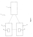
- FIG. 5 schematically shows a block diagram of an example of a system according to an embodiment of the invention.
- the system of Figure 5 is an example of the system according to the fourth aspect of the invention.
- the description of the system according to the fourth aspect is correspondingly valid for the system of Figure 5 .
- the system 6 of Figure 5 comprises a plurality of LED drivers 1a and 1b, wherein each of the plurality of LED drivers 1a and 1b is the LED driver of Figure 1 . Therefore, the above description of the LED driver according to the first aspect of the invention as well as the description of Figures 1 to 4 is correspondingly valid for the LED drivers 1a and 1b of Figure 5 .
- the number of LED drivers 1a and 1b of the system 6 of Figure 5 is only by way of example and, thus, may be greater than two LED drivers.
- each of the LED drivers 1a and 1b may comprise a data storage 2a respectively 2b corresponding to the data storage 2 of the LED driver 1 of Figure 1 .
- the LED drivers 1a and 1b may be configured to communicate with each other wirelessly and/or wired, as indicated by the dashed dotted line.
- the LED drivers 1a and 1b may be electrically connected via a bus system (e.g. a wired bus) with each other.
- At least one LED driver of the plurality of LED drivers 1a and 1b may be configured to provide, in case the trigger occurs at the LED driver, the secured data to at least one other LED driver of the plurality of LED drivers 1a and 1b and/or to an optional control center 5.
- the optional control center 5 may be part of the system 6.
- the LED driver 1a may provide the secured data to the other LED driver 1b and/or to the optional control center 5.
- At least two LED drivers of the plurality of LED drivers 1a and 1b may be configured to provide, in case the trigger occurs at one or more of the at least two LED drivers, the respective secured data to the respective other LED driver of the at least two LED drivers and/or the optional control center 5.
- the two LED drivers 1a and 1b may provide, in case the trigger occurs at the LED driver 1a and/or the LED driver 1b, the respective secured data to the respective other LED driver.
- the LED driver 1a may provide the secured data (secured by the LED driver 1a) to the LED driver 1b and the LED driver 1b may provide the secured data (secured by the LED driver 1b) to the LED driver 1a.
- the two LED drivers 1a and 1b may provide, in case the trigger occurs at the LED driver 1a and/or the LED driver 1b, the respective secured data to the optional control center 5.
- the plurality of LED drivers 1a and 1b may be configured to communicate with the control center 5 wirelessly and/or wired.
- the LED drivers 1a and 1b may be electrically connected via a bus system (e.g. a wired bus) with the control center 5.
Abstract
Description
- The present invention relates to a light emitting diode driver (LED driver), a luminaire comprising such a LED driver and a LED light source, a method for operating a LED driver and a system comprising a plurality of LED drivers.
- A LED driver is a device used for driving a LED light source, such as at least one LED or a LED module comprising at least one LED. The LED driver is configured to electrically supply the LED light source enabling the LED light source to emit light. The LED driver may control the light emission of the LED light source via the electrical supply of the LED light source. For example, by decreasing an electrical power supplied to the LED light source the LED driver may decrease light intensity of the light emission (i.e. the LED driver may perform dimming) and vice versa.
- During the operation of an LED driver several events may occur, which may disturb or interrupt operation of the LED driver (and light emission of a LED light source being driven by the LED driver). Such events may even damage the LED driver. Such events may comprise a short-circuit of the LED light source when being driven by the LED driver, sudden voltage and/or current spikes provided to the LED driver and/or in the LED driver etc.
- Therefore, it is an object of the present invention to provide a LED driver that enables dealing with or countering events that may occur during operation of the LED driver.
- These and other objects, which become apparent upon reading the following description, are solved by the subject-matter of the independent claim. The dependent claims refer to preferred embodiments of the invention.
- According to a first aspect of the invention, a light emitting diode driver (LED driver) is provided. The LED driver comprises a data storage for sequentially storing data of an operation of the LED driver according to a circular buffer. The LED driver is configured to continuously monitor and store the data of the operation of the LED driver sequentially in the data storage. Further, the LED driver is configured to secure, in case a trigger occurs, at least part of the data stored in the data storage at a point in time at which the trigger occurred and corresponding to a time period before the point in time from being overwritten.
- With other words, the present invention proposes continuously monitoring data of an operation of a LED driver and sequentially storing the continuously monitored data in a data storage of the LED driver according to a circular buffer. In case a trigger occurs, the data that are stored in the data storage at a point in time of the trigger and that correspond to a time period before the point in time of the trigger may be secured from being overwritten. This allows searching for the reasons of an event that may occur during the operation of the LED driver. Namely, as soon as such an event is detected the trigger may be caused and, thus, the aforementioned data of the data storage that are stored in the data storage when the trigger occurred and, thus, the event occurred may be secured from being overwritten. Since these data comprise the data of the operation of the LED driver that were continuously monitored during the time period before the point in time of the trigger, they may be used for analyzing what conditions or type of data of the operation of the LED driver lead to the event that caused the trigger. This information may then be used for pre-detecting that the event will occur before the event actually occurs by analyzing the continuously monitored data of the operation of the LED driver, e.g. comparing the monitored data with the secured data that lead to the event. This allows preventing the event from occurring again in the future by allowing the LED driver or another entity, e.g. a central processing unit (may be a central control unit or a control center) or a person, to perform counter measurements.
- The use of the data storage is advantageous. Namely, the data storage is configured to sequentially store the continuously monitored data according to a circular buffer. As a result, if the data storage reaches its maximum capacity (i.e. there is no empty storage space) when sequentially storing the continuously monitored data, the data storage overwrites the already stored data beginning with the oldest data stored in the data storage (i.e. beginning with the data stored for the longest time period in the data storage). Therefore, the continuously stored data is stored in the data storage for a certain time period, wherein this time period depends on the total capacity of the data storage and the speed of continuously monitoring and storing the data sequentially in the data storage. This is acceptable as long as no trigger (e.g. due to an event) occurs, because in this case the data is not required for an analysis. Since the data of the time period before the point in time at which the triggered occurred may be secured from being overwritten, the data storage still allows an analysis of data that were monitored in the past with regard to the point in time of the trigger.
- Storing the data corresponding to a time period, e.g. the time period before the point in time at which the trigger occurred, allows analyzing a time course of the data, i.e. how the data changed over time. For example, voltage data corresponding to a time period allow analyzing a time course of the voltage data during the time period, i.e. analyzing a time course of the voltage indicated or represented by the voltage data.
- In the light of the above, the LED driver allows an error analysis and search for the reasons of an event occurring during the operation of the LED driver (e.g. conditions that lead to the event) and, thus, is advantageous for reducing or preventing events that are not desired from occurring during the operation of the LED driver. In addition, the LED driver allows determining what event (e.g. what kind of event) occurred during the operation of the LED driver that caused the trigger.
- The data of the operation of the LED driver are data measured and/or obtained during the operation of the LED driver. For example, the data of the operation of the LED driver may be or may comprise parameters or values of the operation of the LED driver that are measured and/or obtained during the operation of the LED driver. The LED driver may be configured to continuously monitor the data of the operation of the LED driver by continuously measuring and/or obtaining the data.
- The passage "the LED driver is configured to continuously monitor and store the data of the operation of the LED driver sequentially in the data storage" may mean that the LED driver is configured to continuously monitor the data of the operation of the LED driver and to sequentially store the continuously monitored data in the data storage. In other words, data that is monitored at a point in time are also stored at the point in time (optionally with a negligible time delay that may be caused by the process of storing) in the data storage.
- The data storage may be referred to as circular buffer storage. The term "ring buffer" may be used as a synonym for the term "circular buffer". The data storage is configured to work like a circular buffer, i.e. perform the function of a circular buffer for sequentially storing the continuously monitored data. That is, the data storage may be configured to sequentially store data and start sequentially overwriting the data starting with the oldest or longest stored data when the data storage is full (i.e. there is no empty storage space).
- The time period before the point in time may be directly before the point in time. The time period may be adjacent to the point in time laying before the point in time. The term "adjacent" may be understood as "directly adjacent". Thus, the time period before the point in time may end with the point in time at which the trigger occurred. Optionally, the time period may comprise the point in time, at which the trigger occurred. That is, the data corresponding to the time period before the point in time at which the trigger occurred may comprise the data corresponding to the point in time at which the trigger occurred.
- The term "time" or "time point" may be used as a synonym for the term "point in time". The time period before the point in time at which the trigger occurred may be referred to as "first time period". The point in time at which the trigger occurred may be referred to as "first point in time". The passage "point in time of the trigger" may be used as a synonym for the passage "point in time at which the trigger occurred".
- Optionally, the LED driver may be configured to secure, in case the trigger occurs, the data (i.e. all the data) stored in the data storage at the point in time at which the trigger occurred and corresponding to the time period before the point in time from being overwritten.
- The data corresponding to the time period before the point in time at which the trigger occurred are the data of the operation of the LED driver that were continuously monitored during said time period. The data corresponding to the point in time at which the trigger occurred are the data of the operation of the LED driver that were monitored at the point in time.
- Optionally, the LED driver is configured to additionally secure, in case the trigger occurs, at least part of the data stored in the data storage at a second point in time after the point in time at which the trigger occurred and corresponding to a second time period after the point in time from being overwritten.
- In other words, the LED driver may be configured to secure, in case the trigger occurs, at least part of the data stored in the data storage at the first point in time at which the trigger occurred and corresponding to the first time period before the first point in time as well as of the data stored in the data storage at the second point in time after the first point in time and corresponding to the second time period after the first point in time from being overwritten.
- The second time period after the first point in time may be directly after the first point in time. The second time period may be adjacent to the first point in time laying after the first point in time. The term "adjacent" may be understood as "directly adjacent". Thus, the second time period after the first point in time may start with the first point in time (i.e. with the point in time at which the trigger occurred). In addition or alternatively, the second time period after the first point in time may end with the second point in time. Optionally, the second time period may comprise the point in time, at which the trigger occurred. The second time period may be referred to as "time period after the point in time at which the trigger occurred".
- Optionally, the LED driver may be configured to secure, in case the trigger occurs, the data (i.e. all the data) stored in the data storage at the second point in time and corresponding to the second time period after the first point in time from being overwritten.
- The data corresponding to the second time period are the data of the operation of the LED driver that were continuously monitored during the second time period.
- The LED driver may be configured to secure the respective data from being overwritten by storing the respective data in a second data storage of the LED driver. In addition or alternatively, the LED driver may be configured to secure the respective data from being overwritten by providing the respective data to outside the LED driver. For example, the LED driver may be configured to secure the respective data from being overwritten by providing the respective data to at least one other LED driver and/or a central processing unit (e.g. a control center).
- The respective data may be the data stored in the data storage at the first point in time at which the trigger occurred and corresponding to the time period before the first point in time or at least part of the aforementioned data. Alternatively, the respective data may be the data stored in the data storage at the first point in time at which the trigger occurred and corresponding to the time period before the first point in time as well as the data stored in the data storage at the second point in time after the first point in time and corresponding to the second time period after the first point in time or at least part of the aforementioned data.
- The second data storage may be configured to store the respective data without overwriting data. For example, the second data storage may be configured to sequentially store the respective data without overwriting data. Optionally, the second data storage may be configured to delete data when controlled to do so (e.g. by the LED driver itself or from outside the LED driver, such as from a person or a central control unit/control center).
- The LED driver may be configured to perform a wireless and/or wired communication with one or more entities outside the LED driver, such as at least one other LED driver and/or a central processing unit (e.g. a control center), for providing the respective data to outside the LED driver.
- The LED driver may be configured to be electrically connected via a bus system (e.g. a wired bus) with the at least one other LED driver and/or a central processing unit.
- The LED driver may be configured to cause the trigger at one or more other LED drivers each being a LED driver according to the first aspect, in case the trigger occurs at the LED driver. The one or more other LED drivers may be neighboring LED drivers of the LED driver. Alternatively, the LED driver and the one or more other LED drivers may be grouped in a group (e.g. functional group).
- Optionally, the LED driver is configured to obtain information on an event, which caused the trigger, by processing the secured data.
- Optionally, the LED driver is configured to determine what event caused the trigger (e.g. what kind of event) by processing the secured data. The LED driver may be configured to search for or determine the reasons of an event that caused the trigger (e.g. conditions that lead to the event). For this, the LED driver may be configured to process the secured data. The LED driver may be configured to pre-detect or predict occurrence of the event in the future by analyzing the continuously monitored data using the obtained information and/or the secured data. For example, the LED driver may be configured to pre-detect or predict occurrence of the event in the future by comparing the continuously monitored data with the secured data (that were secured due to the trigger caused by the event).
- For example, the LED driver may analyze data of a supply voltage (e.g. mains voltage) of the LED driver of the secured data and thereby detect a sudden voltage spike or rise of voltage over a threshold. Due to this detection, the LED driver may determine or come to the conclusion that the event of an over voltage at a LED light source when driven by the LED driver, which caused the trigger, is caused by the sudden voltage spike or rise of voltage over the threshold.
- The LED driver may be configured to provide, in response to a request from outside, e.g. from at least one other LED driver, a central processing unit (e.g. a control center) and/or a person (e.g. user), a result of processing or analyzing the secured data to outside the LED driver, e.g. to the at least one other LED driver, the central processing unit (e.g. a control center) and/or the person (e.g. user).
- Optionally, the LED driver is configured to receive data of an operation of at least one other LED driver corresponding to a respective time period, during which the secured data have been continuously monitored by the LED driver, from outside the LED driver. For example, the LED driver may be configured to receive the data of the operation of the at least one other LED driver corresponding to the respective time period, during which the secured data have been continuously monitored by the LED driver, from the at least one other LED and/or a central processing unit (e.g. a control center).
- The respective time period may comprise or be the first time period optionally comprising the first point in time. Alternatively, the respective time period may comprise or be the first time period and the second time period. The respective time period may optionally comprise the first point in time and/or the second point in time.
- Optionally, the LED driver is configured to obtain information on an event, which caused the trigger, by processing the secured data and the received data.
- Optionally, the LED driver is configured to determine what event caused the trigger (e.g. what kind of event) by processing the secured data and the received data. The LED driver may be configured to search for or determine the reasons of an event that caused the trigger (e.g. conditions that lead to the event). For this, the LED driver may be configured to process the secured data and received data (e.g. correlate the secured data and received data). The LED driver may be configured to pre-detect or predict occurrence of the event in the future by analyzing the continuously monitored data using the obtained information and/or the secured data and received data (e.g. correlating the secured data and received data). For example, the LED driver may be configured to pre-detect or predict occurrence of the event in the future by comparing the continuously monitored data with the secured data (that were secured due to the trigger caused by the event) and the received data.
- Optionally, in case the at least one other LED driver is also a LED driver according to the first aspect and the event also caused the trigger at the at least one other LED driver, the LED driver may be configured to combine or correlate the secured data and the received data for determining the reasons of the event (e.g. conditions that lead to the event) and/or what event caused the trigger (i.e. what kind of event). The LED driver may be configured to pre-detect or predict occurrence of the event in the future by analyzing the continuously monitored data using a correlation of the secured data and the received data.
- The LED driver may be configured to provide, in response to a request from outside, e.g. from at least one other LED driver, a central processing unit (e.g. a control center) and/or a person (e.g. user), a result of processing or analyzing the secured data and received data to outside the LED driver, e.g. to the at least one other LED driver, the central processing unit (e.g. a control center) and/or the person (e.g. user).
- The data of the operation of the LED driver, optionally of the LED driver and the at least one other LED driver, may comprise at least one of the following: one or more electrical parameters input to the respective LED driver, one or more electrical parameters output by the respective LED driver, one or more external commands received by the receptive LED driver, communication data of communication means of the respective LED driver, and one or more internal operation parameters of the respective LED driver.
- The term "respective LED driver" may correspond or be the LED driver according to the first aspect or the aforementioned at least one other LED driver.
- For example, the one or more electrical parameters input to the respective LED driver may comprise or may be an input voltage and/or input current. For example, the one or more electrical parameters output by the respective LED driver may comprise or may be an output voltage and/or output current. For example, the one or more external commands received by the receptive LED driver may comprise or may be a dimming command. For example, the one or more internal operation parameters of the respective LED driver may comprise or may be a frequency of a feed-back control, one or more internal commands, a temperature inside the LED driver, a frequency behavior of an internal driver stage, an error of a feedback control of an internal driver stage, an operation mode of the respective LED driver and/or an operation frequency of the respective LED driver.
- The input voltage and the input current may be mains voltage and mains current, respectively, input to the LED driver or provided to the input of the LED driver. The input voltage and the input current may be the voltage and current, respectively, with which the LED driver is electrically supplied from an external energy source, such as an AC source (e.g. mains) and/or DC source (e.g. a battery or a supply bus). In addition or alternatively, the one or more electrical parameters input to the respective LED driver may comprise or may be an input power (electrical power).
- The LED driver may provide the output voltage and/or output current to a LED light source when the LED driver drives the LED light source (e.g. the LED light source is electrically connected to an output of the LED driver for being driven and, thus, electrically supplied by the LED Driver). The output voltage and the output current may be referred to as LED voltage and LED current, respectively. In addition or alternatively, the one or more electrical parameters output by the respective LED driver may comprise or may be an output power (electrical power).
- The one or more external commands may be DALI and/or DALI-2 commands, i.e. commands according to the DALI and/or DALI-2 standard. DALI ("Digital Adressable Lighting Interface"), also referred to as
DALI Edition 1, and DALI-2, also referred to asDALI Edition 2 being the follow-up standard of DALI, are well known standards in the field of lighting. In addition or alternatively, the external commands may be commands of any other known standard, such as the ZigBee standard etc. The LED driver may comprise communication means for receiving the external commands. The communication means may be or may be referred to as communication circuit, communication module or communication interface. The communication means may be configured to communicate wirelessly and/or wired (via a data bus) with one or more entities (e.g. at least one other LED driver, a central processing and/or control unit, and/or a control center) outside the LED driver. In addition or alternatively, the one or more external commands may comprise or may be, for example, a light color change command, a command for setting an operation mode of the LED driver, a command for setting an electrical parameter, e.g. an output voltage, output current and/or output power, a command for setting an operation frequency of the LED driver and/or any other command(s) known in the field of lighting. - The communication data of communication means of the respective LED driver may comprise or may be data communicated by the communication means and/or data used for communicating by the communication means. The communication means of the respective LED driver may be as outlined above.
- The one or more internal operation parameters of the respective LED driver may comprise or may be
- one or more physical parameters, such as one or more electrical parameters, measured inside the respective LED driver;
- one or more settings of the respective LED driver during the operation of the respective LED driver; and/or
- at least one parameter, at least one value and/or information resulting out of a control (e.g. a feedback control) and/or computation performed by the respective LED driver during the operation of the respective LED drive.
- Physical parameters measured inside the respective LED driver may comprise or may be, for example, a temperature inside the respective LED driver.
- The respective LED driver may comprise one or more LED driver stages forming an electrical supply circuit electrically connected between an input of the respective LED driver and an output of the respective LED driver. A LED light source may be electrically connected to the output of the respective LED driver for being driven and, thus, electrically supplied by the respective LED driver, in particular the electrical supply circuit of the respective LED driver. The one or more LED driver stages may comprise or may be at least one actively switched power converter, such as at least one actively switched AC/DC converter and/or at least one actively switched DC/DC converter. Examples of actively switched converters comprise boost converters, buck converters, flyback converters, resonant converters etc. The electrical supply circuit of the respective LED driver may comprise filter means (e.g. an EMI filter), rectification means (e.g. a full-wave rectifier circuit and/or half-wave rectifier circuit) and/or power factor correction means (PFC means), such as passive PFC means and/or active PFC means. The active PFC means may be implemented by an LED driver stage of the one or more LED driver stages comprising at least one actively switched power converter. Additionally or alternatively, the electrical supply circuit of the respective LED driver, e.g. the one or more driver stages, may comprise any other one or more electrical components known in the art for implementing an LED driver, e.g. an electrical supply function of an LED driver.
- In addition or alternatively, physical parameters measured inside the respective LED driver may comprise or may be, for example, a voltage, current and/or power of at least one of the aforementioned electrical components, such as the at least one driver stage (e.g. a voltage across an inductor of an actively switched power converter, a current through the inductor etc.); a frequency behavior of at least one driver stage; and/or any other physical parameter(s9, such as electrical parameter(s), that may be measured or obtained in a LED driver.
- The one or more settings of the respective LED driver during the operation of the respective LED driver may comprise or may be, for example, an operation mode of the respective LED driver, operation frequency of the respective LED driver, maximum allowable output voltage, output current and/or output power and/or any other known setting(s) of a LED driver.
- An operation mode of the respective LED driver may comprise, for example, an emergency operation mode and a normal operation mode, in case the LED driver is an emergency LED driver for emergency lighting. In addition or alternatively, the operation mode of the respective LED driver may comprise, for example, a mode for controlling switching of an actively switched power converter, such as a continuous conduction mode (CCM), discontinuous conduction mode (DCM) and borderline conduction mode. The operation mode of the respective LED driver may, additionally or alternatively, comprise or be any other operation mode(s) known for operating a LED driver.
- The respective LED driver may comprise control means for controlling components of the respective LED driver (e.g. communication means and/or electrical supply circuit of the respective LED driver). The control means may comprise or be a controller, microcontroller, processor, microprocessor, application-specific integrated circuit (ASIC), field-programmable gate array (FPGA) and/or any other known control means type(s). The control means may be configured to analyze and/or process the data of the operation of the respective LED driver. Therefore, the control means may be referred to as control and processing means.
- The at least one parameter, at least one value and/or information resulting out of a control (e.g. a feedback control) and/or computation performed by the respective LED driver during the operation of the respective LED drive may comprise or be, for example, an error of a feedback control performable by the control means of the respective LED driver and/or a frequency behavior of a driver stage of the electrical supply circuit due to the control of the driver stage by the control means.
- In the light of the above, the data of the operation of the respective LED driver may comprise or may be physical parameters, such as electrical parameters, that are
- provided or input to the respective LED driver,
- provided or output by the respective LED driver, and/or
- measured inside and/or at the LED driver.
- Physical parameters measured at the LED driver may be for example a temperature, light condition, humidity, electromagnetic pollution etc. of an environment of the LED driver.
- In addition or alternatively, the data of the operation of the respective LED driver may comprise or may be at least one parameter, at least one value and/or information received and/or transmitted by the LED driver during the operation of the LED driver, wherein the at least one parameter, at least one value and/or information may impact the operation of the LED driver and/or may be caused by the operation of the LED driver.
- In addition or alternatively, the data of the operation of the respective LED driver may comprise or may be one or more settings of the LED driver during the operation of the respective LED driver, wherein the one or more settings may change during the operation of the respective LED driver.
- In addition or alternatively, the data of the operation of the respective LED driver may comprise or may be at least one parameter, at least one value and/or information resulting out of a control (e.g. a feedback control) and/or computation performed by the respective LED driver during the operation of the respective LED driver.
- Optionally, the LED driver is configured to receive the trigger from outside the LED driver. For example, the LED driver is configured to receive the trigger from at least one other LED driver and/or a central processing unit (e.g. a control center). Optionally, the LED driver is configured to receive the trigger from a person (e.g. a user).
- The LED driver may be configured to provide the secured data to outside, e.g. to at least one other LED driver, a central processing unit (e.g. a control center) and/or a person (e.g. user), in response to a request received from outside (e.g. from the at least one other LED driver, the central processing unit (e.g. the control center) and/or the person (e.g. user)).
- Optionally, the trigger occurs when an event during the operation of the LED driver irrespective of the data is detected. For example, the event may be a short-circuit of an LED light source when the LED light source is driven by the LED driver.
- In addition or alternatively, the event may be, for example, at least one of the following: a disturbance of the external energy supply electrically supplying the LED driver, failure or malfunction of one or more components of the LED driver, an improper operation or use of the LED driver outside the operation boundaries for the LED driver, a sudden change of output power of a LED light source when the LED driver drives the LED light source, etc.
- Optionally, the LED driver is configured to detect the event during the operation of the LED driver irrespective of the data. In addition or alternatively, the LED driver may be configured to receive from outside the LED driver information that the event during the operation of the LED driver irrespective of the data is detected. For example, the LED driver may be configured to receive from at least one other LED driver and/or a central processing unit (e.g. a control center) the information that the event during the operation of the LED driver irrespective of the data is detected.
- Optionally, the trigger occurs when an event in the data stored in the data storage irrespective of the operation of the LED driver is detected.
- For example, the event may be a voltage spike in input voltage data stored in the data storage. In addition or alternatively, the event may be, for example, at least one of the following: a current spike in current data (e.g. input current data), a sudden change in an operation frequency of frequency data, sudden change in temperature data etc. In other words, the event may be a sudden change of one or more different data of the data, an abnormal pattern of one or more different data of the data and/or one or more different data of the data reaching a certain value or threshold.
- Optionally, the LED driver is configured to detect the event in the data stored in the data storage irrespective of the operation of the LED driver by analyzing the data stored in the data storage.
- The above description of the LED driver according to the first aspect may be valid for the above mentioned at least one further LED driver. The aforementioned processing unit (central processing unit) may be or may be part of a control center.
- In order to achieve the LED driver according to the first aspect of the invention, some or all of the above described optional features may be combined with each other.
- According to a second aspect of the invention, a luminaire is provided. The luminaire comprises a LED driver according to the first aspect of the invention, as described above, and a LED light source. The LED driver is configured to electrically supply the LED light source.
- The above description with regard to the LED driver according to the first aspect of the invention is correspondingly valid for the luminaire according to the second aspect of the invention.
- The LED light source may be at least one light emitting diode (LED) and/or a LED module comprising at least one LED. Any known LEDs may be used for implementing the LED light source (e.g. organic LEDs, inorganic LEDs etc.).
- With regard to the luminaire, the passage "outside the LED driver" may mean "outside the luminaire". With regard to the luminaire, the processing unit (central processing unit) outside the LED driver described in the description of the LED driver of the first aspect, may be or may be part of control means of the luminaire.
- The luminaire according to the second aspect of the invention achieves the same advantages as the LED driver according to the first aspect of the invention.
- In order to achieve the luminaire according to the second aspect of the invention, some or all of the above described optional features may be combined with each other.
- According to a third aspect of the invention, a method for operating a LED driver is provided. The method comprises continuously monitoring and storing data of an operation of the LED driver sequentially in a data storage according to a circular buffer. Further the method comprises, in case a trigger occurs, securing at least part of the data stored in the data storage at a point in time at which the trigger occurred and corresponding to a time period before the point in time from being overwritten.
- The above description with regard to the LED driver according to the first aspect of the invention is correspondingly valid for the method according to the third aspect of the invention.
- The method according to the third aspect of the invention achieves the same advantages as the LED driver according to the first aspect of the invention.
- In order to achieve the method according to the third aspect of the invention, some or all of the above described optional features may be combined with each other.
- According to a fourth aspect of the invention, a system is provided. The system comprises a plurality of LED drivers according to the first aspect of the invention, as described above. At least one LED driver of the plurality of LED drivers is configured to provide, in case the trigger occurs at the LED driver, the secured data to a control center and/or at least one other LED driver of the plurality of LED drivers. In addition or alternatively, at least two LED drivers of the plurality of LED drivers are configured to provide, in case the trigger occurs at one or more of the at least two LED drivers, the respective secured data to a control center and/or the respective other LED driver of the at least two LED drivers.
- The above description with regard to the LED driver according to the first aspect of the invention is correspondingly valid for the system according to the fourth aspect of the invention.
- The at least one LED driver may be configured to communicate with the at least one other LED driver wirelessly and/or wired. The at least two LED drivers may be configured to communicate with each other wirelessly and/or wired. The at least two LED drivers may be configured to communicate with the control center wirelessly and/or wired. The plurality of LED drivers may be configured to communicate with each other and/or the control center via a wireless and/or wired communication. The control center may be part of the system. The plurality of LED drivers may be electrically connected via a bus system (e.g. a wired bus) with each other. The plurality of LED drivers and the control center may optionally be electrically connected via a bus system (e.g. a wired bus) with each other.
- Optionally, the control center is configured to determine what event caused the trigger at the at least one LED driver from which the control center received the secured data (e.g. what kind of event) by processing the received secured data. The control center may be configured to search for or determine the reasons of an event (e.g. conditions that lead to the event), which caused the trigger at the at least one LED driver from which the control center received the secured data. For this, the control center may be configured to process the received secured data. The control center may be configured to provide the result of processing the received secured data to the at least one LED driver and optionally to one or more other LED drivers of the plurality of LED drivers.
- The control center may be configured to determine, in case the control center received the secured data from the at least two LED drivers, what event caused the trigger at one or more of the at least two LED drivers (e.g. what kind of event) by processing the secured data received from the at least two LED drivers (e.g. correlate the secured data received from the at least two LED drivers with each other). Optionally, the control center may be configured to search for or determine, in case the control center received the secured data from the at least two LED drivers, the reasons of an event (e.g. conditions that lead to the event), which caused the trigger at one or more of the at least two LED drivers. For this, the control center may be configured to process the secured data received from the at least two LED drivers (e.g. correlate the secured data received from the at least two LED drivers with each other). The control center may be configured to provide the result of processing the received secured data to the at least two LED drivers and optionally to one or more other LED drivers of the plurality of LED drivers.
- The at least one LED driver may be configured to provide the secured data to the control center and/or at least one other LED driver in response to a request received from outside the at least one LED driver, e.g. from the control center and/or a person (e.g. user). The at least two LED drivers may be configured to provide the respective secured data to the control center and/or the respective other LED driver of the at least two LED drivers in response to a request received from outside the at least one LED driver, e.g. from the control center and/or a person (e.g. user).
- One or more of the plurality of LED drivers may be configured to provide the secured data to outside, e.g. to the control center and/or to a person (e.g. user), in response to a request received from outside, e.g. from the control center and/or the person (e.g. user).
- The system according to the fourth aspect of the invention may be a luminaire.
- The description of the system of the fourth aspect, e.g. the control center, may be correspondingly valid for the LED driver according to the first aspect of the invention.
- The system according to the fourth aspect of the invention achieves the same advantages as the LED driver according to the first aspect of the invention.
- In order to achieve the system according to the fourth aspect of the invention, some or all of the above described optional features may be combined with each other.
- It has to be noted that all devices, elements, units and means described in the present application could be implemented in software or hardware elements or any kind of combination thereof. All steps which are performed by the various entities described in the present application as well as the functionalities described to be performed by the various entities are intended to mean that the respective entity is adapted to or configured to perform the respective steps and functionalities.
- In the following, the invention is described exemplarily with reference to the enclosed Figures, in which
- Figure 1
- schematically shows a block diagram of an example of a LED driver according to an embodiment of the invention;
- Figures 2 to 4
- schematically show an example of a state of a data storage of the LED driver of
Figure 1 for three different points in time; and - Figure 5
- schematically shows a block diagram of an example of a system according to an embodiment of the invention.
- In the Figures, corresponding elements have the same reference signs. The proportions and dimensions of the elements shown in the Figures do not represent the components of the LED driver(s) and optionally a control center to scale, but are merely chosen to describe the structure and function of the LED driver(s) and optionally the control center.
-
Figure 1 schematically shows a block diagram of an example of a LED driver according to an embodiment of the invention. The LED driver ofFigure 1 is an example of the LED driver according to the first aspect of the invention. The description of the LED driver according to the first aspect is correspondingly valid for the LED driver ofFigure 1 . - The
LED driver 1 ofFigure 1 comprises adata storage 2 for sequentially storing, according to a circular buffer, data of an operation of theLED driver 1. TheLED driver 1 is configured to continuously monitor and store the data of the operation of theLED driver 1 sequentially in thedata storage 2. Further, theLED driver 1 is configured to secure, in case a trigger occurs, at least part of the data stored in thedata storage 2 at a point in time at which the trigger occurred and corresponding to a time period before the point in time from being overwritten. - Optionally, the
LED driver 1 is configured to additionally secure, in case the trigger occurs, at least part of the data stored in thedata storage 2 at a second point in time after the point in time at which the trigger occurred and corresponding to a second time period after the point in time from being overwritten. - Examples of how the
LED driver 1 may secure data stored in thedata storage 2 is described in more detail with regard toFigures 2 to 4 . - For further information on possible implantation forms of the
LED driver 1, e.g. of the structure and/or function of theLED driver 1, as well as on the data of the operation of theLED driver 1 reference is made to the corresponding description of the LED driver according to the first aspect of the invention. - As shown in
Figure 1 , aLED light source 3 may be electrically connected to the LED driver 1 (in particular to an output of the LED driver 1) for being driven and, thus, electrically supplied by theLED driver 1. The LEDlight source 3 may be at least one light emitting diode (LED) and/or a LED module comprising at least one LED. Any known LEDs may be used for implementing the LED light source 3(e.g. organic LEDs, inorganic LEDs etc.). - The
LED driver 1 and the LEDlight source 3 may form or be part of aluminaire 4. Theluminaire 4 ofFigure 1 may be an example of the luminaire according to the second aspect of the invention. The description of the luminaire according to the second aspect is correspondingly valid for theluminaire 4 ofFigure 1 . -
Figures 2 to 4 schematically show an example of a state of a data storage of the LED driver ofFigure 1 for three different points in time. -
Figure 2 shows the state of thedata storage 2 of theLED driver 1 ofFigure 1 at the point in time T1, at which the trigger occurred (T = T1). Thus, as shown inFigure 2 , at the point in time T1 theLED driver 1 may secure at least part of the data D1 stored in thedata storage 2 at the point in time T1 and corresponding to a time period P1 before the point in time T1 from being overwritten. - According to the example of
Figure 2 , the time period P1 is directly before the point in time T1. That is, the time period P1 ends at the point in time T1. This may be differently, that is the time period P1 does not need to be directly before the point in time T1. Optionally, the time period P1 may comprise the point in time T1, at which the trigger occurred. That is, the data D1 corresponding to the time period P1 before the point in time T1 at which the trigger occurred may comprise the data D2 corresponding to the point in time T1. - As indicated in
Figure 2 , at the point in time T1 theLED driver 1 stores the data monitored by the LED driver at the point in time T1. Thus, in case thedata storage 2 is full (no empty storage space available), the oldest data stored in thedata storage 2 are overwritten by current data (which are in the case ofFigure 2 the data D2 monitored at the point in time T1). The direction of sequentially storing or writing and, thus, potentially overwriting previously stored data is indicated inFigure 2 by an arrow in counter-clockwise direction. In theFigure 2 , the data D2 at the point in time T1 is the newest data stored in the data storage (i.e. current data monitored by the LED driver at the point in time Ti), wherein in a clockwise direction the data gets older, i.e. was monitored and stored more in the past with regard to the point in time T1 (i.e. the current point in time). -
Figure 3 shows the state of thedata storage 2 of theLED driver 1 ofFigure 1 at a second point in time T2 (T = T2) for securing data of thedata storage 2 after the point in time T1, at which the trigger occurred. The above description ofFigure 2 is correspondingly valid forFigure 3 . As shown inFigure 3 , at the second point in time T2 theLED driver 1 may additionally secure at least part of the data D3 stored in thedata storage 2 at the second point in time T2 and corresponding to a second time period P2 after the point in time T1 from being overwritten. - According to the example of
Figure 3 , the second time period P2 is directly after the point in time T1. That is, the second time period P2 begins at the point in time T1. This may be differently, that is the second time period P2 does not need to be directly after the point in time T1. The second time period P2 may end at the second point in time T2. This may be differently as shown inFigure 4 , wherein the second point in time for securing data is not the point in time T2 but another point in time T3 after the point in time T2. - As indicated in
Figure 3 , at the second point in time T2 theLED driver 1 stores the data monitored by theLED driver 1 at the second point in time T2. Thus, in case thedata storage 2 is full (no empty storage space available), the oldest data stored in thedata storage 2 are overwritten by current data (which are in the case ofFigure 3 the data monitored at the second point in time T2). The direction of sequentially storing or writing and, thus, potentially overwriting previously stored data is indicated inFigure 3 by an arrow in counter-clockwise direction. -
Figure 4 shows the state of thedata storage 2 of theLED driver 1 ofFigure 1 at a second point in time T3 (T = T3) for securing data of thedata storage 2 after the point in time T1, at which the trigger occurred. The above description ofFigures 2 and3 is correspondingly valid forFigure 4 . As shown inFigure 4 , at the second point in time T3 theLED driver 1 may additionally secure at least part of the data D3 stored in thedata storage 2 at the second point in time T3 and corresponding to a second time period P2 after the point in time T1 from being overwritten. - According to the example of
Figure 4 , the second time period P2 is directly after the point in time T1. That is, the second time period P2 begins at the point in time T1. This may be differently, that is the second time period P2 does not need to be directly after the point in time T1. The second time period P2 may end at a point in time T2 before the second point in time T3 for securing data, as shown inFigure 4 . - As indicated in
Figure 4 , at the second point in time T3 theLED driver 1 stores the data monitored by theLED driver 1 at the second point in time T3. Thus, in case thedata storage 2 is full (no empty storage space available), the oldest data stored in thedata storage 2 are overwritten by current data (which are in the case ofFigure 4 the data monitored at the second point in time T3). The direction of sequentially storing or writing and, thus, potentially overwriting previously stored data is indicated inFigure 4 by an arrow in counter-clockwise direction. - For further information on how the
LED driver 1 ofFigures 1 to 4 may be configured to store and secure data of the operation of theLED driver 1 reference is made to the above description of the LED driver according to the first aspect of the invention.Figure 5 schematically shows a block diagram of an example of a system according to an embodiment of the invention. The system ofFigure 5 is an example of the system according to the fourth aspect of the invention. The description of the system according to the fourth aspect is correspondingly valid for the system ofFigure 5 . - The
system 6 ofFigure 5 comprises a plurality ofLED drivers 1a and 1b, wherein each of the plurality ofLED drivers 1a and 1b is the LED driver ofFigure 1 . Therefore, the above description of the LED driver according to the first aspect of the invention as well as the description ofFigures 1 to 4 is correspondingly valid for theLED drivers 1a and 1b ofFigure 5 . The number ofLED drivers 1a and 1b of thesystem 6 ofFigure 5 is only by way of example and, thus, may be greater than two LED drivers. As indicated inFigure 5 , each of theLED drivers 1a and 1b may comprise adata storage 2a respectively 2b corresponding to thedata storage 2 of theLED driver 1 ofFigure 1 . TheLED drivers 1a and 1b may be configured to communicate with each other wirelessly and/or wired, as indicated by the dashed dotted line. TheLED drivers 1a and 1b may be electrically connected via a bus system (e.g. a wired bus) with each other. - At least one LED driver of the plurality of
LED drivers 1a and 1b may be configured to provide, in case the trigger occurs at the LED driver, the secured data to at least one other LED driver of the plurality ofLED drivers 1a and 1b and/or to anoptional control center 5. Optionally, theoptional control center 5 may be part of thesystem 6. For example, in case at the LED driver 1a the trigger occurs, the LED driver 1a may provide the secured data to theother LED driver 1b and/or to theoptional control center 5. - In addition or alternatively, at least two LED drivers of the plurality of
LED drivers 1a and 1b may be configured to provide, in case the trigger occurs at one or more of the at least two LED drivers, the respective secured data to the respective other LED driver of the at least two LED drivers and/or theoptional control center 5. For example, the twoLED drivers 1a and 1b may provide, in case the trigger occurs at the LED driver 1a and/or theLED driver 1b, the respective secured data to the respective other LED driver. That is, in case the trigger occurs at the LED driver 1a and/or theLED driver 1b, the LED driver 1a may provide the secured data (secured by the LED driver 1a) to theLED driver 1b and theLED driver 1b may provide the secured data (secured by theLED driver 1b) to the LED driver 1a. In addition or alternatively, the twoLED drivers 1a and 1b may provide, in case the trigger occurs at the LED driver 1a and/or theLED driver 1b, the respective secured data to theoptional control center 5. - As indicated in
Figure 1 , the plurality ofLED drivers 1a and 1b may be configured to communicate with thecontrol center 5 wirelessly and/or wired. TheLED drivers 1a and 1b may be electrically connected via a bus system (e.g. a wired bus) with thecontrol center 5. - For further information on the system of
Figure 5 , e.g. possible implementation forms of the function of theLED drivers 1a and 1b and theoptional control center 5, reference is made to the above description of the system according to the fourth aspect of the invention. - In the claims as well as in the description the word "comprising" does not exclude other elements or steps and the indefinite article "a" or "an" does not exclude a plurality. A single element or other unit may fulfill the functions of several entities or items recited in the claims. The mere fact that certain measures are recited in the mutual different dependent claims does not indicate that a combination of these measures cannot be used in an advantageous implementation.
Claims (15)
- A light emitting diode driver (1), LED driver, comprising- a data storage (2) for sequentially storing data of an operation of the LED driver (1) according to a circular buffer; wherein- the LED driver (1) is configured to- continuously monitor and store the data of the operation of the LED driver (1) sequentially in the data storage (2), and- secure, in case a trigger occurs, at least part of the data (Di) stored in the data storage (2) at a point in time (Ti) at which the trigger occurred and corresponding to a time period (Pi) before the point in time (Ti) from being overwritten.
- The LED driver (1) according to claim 1, wherein- the LED driver (1) is configured to additionally secure, in case the trigger occurs, at least part of the data (D3) stored in the data storage (2) at a second point in time (T2, T3) after the point in time (Ti) at which the trigger occurred and corresponding to a second time period (P2) after the point in time (Ti) from being overwritten.
- The LED driver (1) according to claim 1 or 2, wherein the LED driver (1) is configured to secure the respective data (Di, D3) from being overwritten by- storing the respective data (D2, D3) in a second data storage of the LED driver (1), and/or- providing the respective data (D2, D3) to outside the LED driver (1), optionally to at least one other LED driver and/or a central processing unit.
- The LED driver (1) according to any one of the previous claims, wherein- the LED driver (1) is configured to obtain information on an event, which caused the trigger, by processing the secured data (D2, D3).
- The LED driver (1) according to any one of the previous claims, wherein- the LED driver (1) is configured to receive data of an operation of at least one other LED driver corresponding to a respective time period, during which the secured data (Di, D3) have been continuously monitored by the LED driver (1), from outside the LED driver (1), optionally from the at least one other LED and/or a central processing unit.
- The LED driver (1) according to claim 5, wherein- the LED driver (1) is configured to obtain information on an event, which caused the trigger, by processing the secured data (Di, D3) and the received data.
- The LED driver (1) according to any one of the previous claims, wherein the data of the operation of the LED driver (1), optionally of the LED driver (1) and the at least one other LED driver, comprise at least one of the following:- one or more electrical parameters input to the respective LED driver, for example an input voltage and/or input current;- one or more electrical parameters output by the respective LED driver, for example an output voltage and/or output current;- one or more external commands received by the receptive LED driver, for example a dimming command;- communication data of communication means of the respective LED driver; and- one or more internal operation parameters of the respective LED driver, for example a frequency of a feed-back control, one or more internal commands, a temperature inside the LED driver, a frequency behavior of an internal driver stage, an error of a feedback control of an internal driver stage, an operation mode of the respective LED driver and/or an operation frequency of the respective LED driver.
- The LED driver (1) according to any one of the previous claims, wherein- the LED driver (1) is configured to receive the trigger from outside the LED driver, optionally from at least one other LED driver and/or a central processing unit.
- The LED driver (1) according to any one of the previous claims, wherein- the trigger occurs when an event during the operation of the LED driver (1) irrespective of the data is detected, for example, the event being a short-circuit of an LED light source (3) when the LED light source (3) is driven by the LED driver (1).
- The LED driver (1) according to claim 9, wherein the LED driver (1) is configured to- detect the event during the operation of the LED driver (1) irrespective of the data, and/or- receive from outside the LED driver (1), optionally from at least one other LED driver and/or a central processing unit, information that the event during the operation of the LED driver (1) irrespective of the data is detected.
- The LED driver (1) according to any one of the previous claims, wherein- the trigger occurs when an event in the data stored in the data storage (2) irrespective of the operation of the LED driver (1) is detected, for example, the event being a voltage spike in input voltage data stored in the data storage (2).
- The LED driver (1) according to claim 11, wherein- the LED driver (1) is configured to detect the event in the data stored in the data storage (2) irrespective of the operation of the LED driver (1) by analyzing the data stored in the data storage (2).
- A luminaire (4) comprising- a LED driver (1) according to any one of the previous claims, and- a LED light source (3); wherein- the LED driver (1) is configured to electrically supply the LED light source (3).
- A method for operating a LED driver, wherein the method comprises:- continuously monitoring and storing data of an operation of the LED driver sequentially in a data storage according to a circular buffer; and- in case a trigger occurs, securing at least part of the data stored in the data storage at a point in time at which the trigger occurred and corresponding to a time period before the point in time from being overwritten.
- A system (6) comprising a plurality of LED drivers (1a, 1b) according to any one of claims 1 to 12, wherein- at least one LED driver of the plurality of LED drivers (1a, 1b) is configured to provide, in case the trigger occurs at the LED driver, the secured data to a control center and/or at least one other LED driver of the plurality of LED drivers (1a, 1b); and/or- at least two LED drivers of the plurality of LED drivers (1a, 1b) are configured to provide, in case the trigger occurs at one or more of the at least two LED drivers, the respective secured data to a control center (5) and/or the respective other LED driver of the at least two LED drivers.
Priority Applications (2)
| Application Number | Priority Date | Filing Date | Title |
|---|---|---|---|
| EP22170919.9A EP4271137A1 (en) | 2022-04-29 | 2022-04-29 | Led driver, luminaire, method for operating a led driver and system comprising a plurality of led drivers |
| PCT/EP2023/060169 WO2023208692A1 (en) | 2022-04-29 | 2023-04-19 | Led driver, luminaire, method for operating a led driver and system comprising a plurality of led drivers |
Applications Claiming Priority (1)
| Application Number | Priority Date | Filing Date | Title |
|---|---|---|---|
| EP22170919.9A EP4271137A1 (en) | 2022-04-29 | 2022-04-29 | Led driver, luminaire, method for operating a led driver and system comprising a plurality of led drivers |
Publications (1)
| Publication Number | Publication Date |
|---|---|
| EP4271137A1 true EP4271137A1 (en) | 2023-11-01 |
Family
ID=81448457
Family Applications (1)
| Application Number | Title | Priority Date | Filing Date |
|---|---|---|---|
| EP22170919.9A Pending EP4271137A1 (en) | 2022-04-29 | 2022-04-29 | Led driver, luminaire, method for operating a led driver and system comprising a plurality of led drivers |
Country Status (2)
| Country | Link |
|---|---|
| EP (1) | EP4271137A1 (en) |
| WO (1) | WO2023208692A1 (en) |
Citations (3)
| Publication number | Priority date | Publication date | Assignee | Title |
|---|---|---|---|---|
| US20120242507A1 (en) * | 2011-03-22 | 2012-09-27 | Lumination Llc | Led traffic signal fault logging system and method |
| US20120313534A1 (en) * | 2011-06-08 | 2012-12-13 | GE Lighting Solutions, LLC | Low profile lamp using tir lens |
| US20150115811A1 (en) * | 2013-10-25 | 2015-04-30 | Cree, Inc. | Detection of linear and pwm dimming in a solid state lighting device |
-
2022
- 2022-04-29 EP EP22170919.9A patent/EP4271137A1/en active Pending
-
2023
- 2023-04-19 WO PCT/EP2023/060169 patent/WO2023208692A1/en unknown
Patent Citations (3)
| Publication number | Priority date | Publication date | Assignee | Title |
|---|---|---|---|---|
| US20120242507A1 (en) * | 2011-03-22 | 2012-09-27 | Lumination Llc | Led traffic signal fault logging system and method |
| US20120313534A1 (en) * | 2011-06-08 | 2012-12-13 | GE Lighting Solutions, LLC | Low profile lamp using tir lens |
| US20150115811A1 (en) * | 2013-10-25 | 2015-04-30 | Cree, Inc. | Detection of linear and pwm dimming in a solid state lighting device |
Also Published As
| Publication number | Publication date |
|---|---|
| WO2023208692A1 (en) | 2023-11-02 |
Similar Documents
| Publication | Publication Date | Title |
|---|---|---|
| CN109479351B (en) | Color-based half-life prediction system | |
| CA2764812C (en) | Systems and apparatus for automatically deriving and modifying personal preferences applicable to multiple controllable lighting networks | |
| US11963272B2 (en) | Data acquisition methods and apparatus for a network connected LED driver | |
| EP2904875B1 (en) | Solid state lighting device and driver configured for failure detection and recovery | |
| EP2533608B1 (en) | Multiple channel light source power supply with output protection | |
| US20150257229A1 (en) | Lighting device monitor and communication apparatus | |
| KR101283321B1 (en) | LED fault detector | |
| KR20140102267A (en) | Dimming control for emergency lighting systems | |
| US9974147B1 (en) | Integrated LED driver for wireless communication | |
| US9247592B2 (en) | Operating device with power factor correction and ripple limitation by change in operation | |
| US9313836B2 (en) | Circuit and method for detecting the duration of the interruption of a mains input | |
| WO2015173681A1 (en) | Emergency lighting system | |
| EP3017656B1 (en) | Method and apparatus for conveying aggregate presence information using light | |
| EP2706820A2 (en) | Solid-state light-emitting element drive device, lighting system and lighting fixture | |
| EP4271137A1 (en) | Led driver, luminaire, method for operating a led driver and system comprising a plurality of led drivers | |
| CN109952813B (en) | Method for operating a lighting device, operating device and lighting unit | |
| GB2572371A (en) | Emergency lighting power supply with combined zero-current detection | |
| CN109155121B (en) | System and method for displaying messages in a column-by-column format through an array of LEDs connected to a circuit of a compressor | |
| WO2023208995A1 (en) | Artificial intelligence-based lifetime analytic calculations for intelligent devices of building infrastructure systems | |
| WO2014086791A1 (en) | Circuit device and electronic apparatus | |
| WO2023209101A1 (en) | Led driver with self-test capabilities | |
| JP2022057361A (en) | Electronic device | |
| JP2012129062A (en) | Semiconductor light emitting element lighting device and lighting equipment using it | |
| WO2017067762A1 (en) | System and method for optimizing occupancy sensor time-out interval |
Legal Events
| Date | Code | Title | Description |
|---|---|---|---|
| PUAI | Public reference made under article 153(3) epc to a published international application that has entered the european phase |
Free format text: ORIGINAL CODE: 0009012 |
|
| STAA | Information on the status of an ep patent application or granted ep patent |
Free format text: STATUS: THE APPLICATION HAS BEEN PUBLISHED |
|
| AK | Designated contracting states |
Kind code of ref document: A1 Designated state(s): AL AT BE BG CH CY CZ DE DK EE ES FI FR GB GR HR HU IE IS IT LI LT LU LV MC MK MT NL NO PL PT RO RS SE SI SK SM TR |
|
| STAA | Information on the status of an ep patent application or granted ep patent |
Free format text: STATUS: REQUEST FOR EXAMINATION WAS MADE |
|
| 17P | Request for examination filed |
Effective date: 20231110 |
|
| RBV | Designated contracting states (corrected) |
Designated state(s): AL AT BE BG CH CY CZ DE DK EE ES FI FR GB GR HR HU IE IS IT LI LT LU LV MC MK MT NL NO PL PT RO RS SE SI SK SM TR |
|
| GRAP | Despatch of communication of intention to grant a patent |
Free format text: ORIGINAL CODE: EPIDOSNIGR1 |
|
| STAA | Information on the status of an ep patent application or granted ep patent |
Free format text: STATUS: GRANT OF PATENT IS INTENDED |
|
| INTG | Intention to grant announced |
Effective date: 20240110 |
|
| GRAS | Grant fee paid |
Free format text: ORIGINAL CODE: EPIDOSNIGR3 |