EP4271084A1 - Random access resource determining method, electronic device and storage medium - Google Patents
Random access resource determining method, electronic device and storage medium Download PDFInfo
- Publication number
- EP4271084A1 EP4271084A1 EP21928540.0A EP21928540A EP4271084A1 EP 4271084 A1 EP4271084 A1 EP 4271084A1 EP 21928540 A EP21928540 A EP 21928540A EP 4271084 A1 EP4271084 A1 EP 4271084A1
- Authority
- EP
- European Patent Office
- Prior art keywords
- bwp
- terminal device
- redcap
- offset
- resource
- Prior art date
- Legal status (The legal status is an assumption and is not a legal conclusion. Google has not performed a legal analysis and makes no representation as to the accuracy of the status listed.)
- Granted
Links
Images



Classifications
-
- H—ELECTRICITY
- H04—ELECTRIC COMMUNICATION TECHNIQUE
- H04W—WIRELESS COMMUNICATION NETWORKS
- H04W74/00—Wireless channel access
- H04W74/002—Transmission of channel access control information
- H04W74/006—Transmission of channel access control information in the downlink, i.e. towards the terminal
-
- H—ELECTRICITY
- H04—ELECTRIC COMMUNICATION TECHNIQUE
- H04L—TRANSMISSION OF DIGITAL INFORMATION, e.g. TELEGRAPHIC COMMUNICATION
- H04L5/00—Arrangements affording multiple use of the transmission path
- H04L5/003—Arrangements for allocating sub-channels of the transmission path
- H04L5/0053—Allocation of signalling, i.e. of overhead other than pilot signals
-
- H—ELECTRICITY
- H04—ELECTRIC COMMUNICATION TECHNIQUE
- H04L—TRANSMISSION OF DIGITAL INFORMATION, e.g. TELEGRAPHIC COMMUNICATION
- H04L1/00—Arrangements for detecting or preventing errors in the information received
- H04L1/12—Arrangements for detecting or preventing errors in the information received by using return channel
- H04L1/16—Arrangements for detecting or preventing errors in the information received by using return channel in which the return channel carries supervisory signals, e.g. repetition request signals
- H04L1/18—Automatic repetition systems, e.g. Van Duuren systems
- H04L1/1829—Arrangements specially adapted for the receiver end
- H04L1/1854—Scheduling and prioritising arrangements
-
- H—ELECTRICITY
- H04—ELECTRIC COMMUNICATION TECHNIQUE
- H04L—TRANSMISSION OF DIGITAL INFORMATION, e.g. TELEGRAPHIC COMMUNICATION
- H04L1/00—Arrangements for detecting or preventing errors in the information received
- H04L1/12—Arrangements for detecting or preventing errors in the information received by using return channel
- H04L1/16—Arrangements for detecting or preventing errors in the information received by using return channel in which the return channel carries supervisory signals, e.g. repetition request signals
- H04L1/18—Automatic repetition systems, e.g. Van Duuren systems
- H04L1/1829—Arrangements specially adapted for the receiver end
- H04L1/1861—Physical mapping arrangements
-
- H—ELECTRICITY
- H04—ELECTRIC COMMUNICATION TECHNIQUE
- H04L—TRANSMISSION OF DIGITAL INFORMATION, e.g. TELEGRAPHIC COMMUNICATION
- H04L5/00—Arrangements affording multiple use of the transmission path
- H04L5/0001—Arrangements for dividing the transmission path
- H04L5/0003—Two-dimensional division
- H04L5/0005—Time-frequency
-
- H—ELECTRICITY
- H04—ELECTRIC COMMUNICATION TECHNIQUE
- H04L—TRANSMISSION OF DIGITAL INFORMATION, e.g. TELEGRAPHIC COMMUNICATION
- H04L5/00—Arrangements affording multiple use of the transmission path
- H04L5/003—Arrangements for allocating sub-channels of the transmission path
- H04L5/0053—Allocation of signalling, i.e. of overhead other than pilot signals
- H04L5/0055—Physical resource allocation for ACK/NACK
-
- H—ELECTRICITY
- H04—ELECTRIC COMMUNICATION TECHNIQUE
- H04L—TRANSMISSION OF DIGITAL INFORMATION, e.g. TELEGRAPHIC COMMUNICATION
- H04L5/00—Arrangements affording multiple use of the transmission path
- H04L5/0091—Signalling for the administration of the divided path, e.g. signalling of configuration information
- H04L5/0092—Indication of how the channel is divided
-
- H—ELECTRICITY
- H04—ELECTRIC COMMUNICATION TECHNIQUE
- H04W—WIRELESS COMMUNICATION NETWORKS
- H04W72/00—Local resource management
- H04W72/20—Control channels or signalling for resource management
- H04W72/21—Control channels or signalling for resource management in the uplink direction of a wireless link, i.e. towards the network
-
- H—ELECTRICITY
- H04—ELECTRIC COMMUNICATION TECHNIQUE
- H04W—WIRELESS COMMUNICATION NETWORKS
- H04W48/00—Access restriction; Network selection; Access point selection
- H04W48/08—Access restriction or access information delivery, e.g. discovery data delivery
- H04W48/12—Access restriction or access information delivery, e.g. discovery data delivery using downlink control channel
-
- H—ELECTRICITY
- H04—ELECTRIC COMMUNICATION TECHNIQUE
- H04W—WIRELESS COMMUNICATION NETWORKS
- H04W74/00—Wireless channel access
- H04W74/08—Non-scheduled access, e.g. ALOHA
- H04W74/0866—Non-scheduled access, e.g. ALOHA using a dedicated channel for access
Definitions
- the disclosure relates to the technical field of wireless communications, and in particular to, methods for determining resources for random access, an electronic device and a storage medium.
- Embodiments of the disclosure provide methods for determining resources for random access, an electronic device and a storage medium, which can clearly define the opportunity when the terminal device receives a paging message.
- embodiments of the present disclosure provide a method for determining resources for random access, which includes the following operation.
- a terminal device with RedCap determines a second common Physical Uplink Control Channel (PUCCH) resource based on a frequency domain position of a first common PUCCH resource and a frequency offset.
- PUCCH Physical Uplink Control Channel
- the second common PUCCH resource is a resource, for sending Hybrid Automatic Repeat Request (HARQ) feedback information, within a bandwidth for the terminal device with RedCap
- the first common PUCCH resource is a resource, for sending HARQ feedback information, corresponding to an initial uplink Bandwidth Part (BWP).
- BWP Bandwidth Part
- embodiments of the present disclosure provide a method for determining resources for random access, which includes the following operation.
- a terminal device with RedCap determines a second common PUCCH resource based on configuration information of a first common PUCCH resource and a bandwidth for the terminal device with RedCap.
- the second common PUCCH resource is a resource, for sending HARQ feedback information, within the bandwidth for the terminal device with RedCap
- the first common PUCCH resource is a resource, for sending HARQ feedback information, corresponding to an initial uplink BWP.
- embodiments of the present disclosure provide a method for determining resources for random access, which includes the following operation.
- a network device determines a second common PUCCH resource based on a frequency domain position of a first common PUCCH resource and a frequency offset.
- the second common PUCCH resource is a resource, for sending HARQ feedback information, within a bandwidth for a terminal device with RedCap
- the first common PUCCH resource is a resource, for sending HARQ feedback information, corresponding to an initial uplink BWP.
- embodiments of the present disclosure provide a method for determining resources for random access, which includes the following operation.
- a network device determines a second common PUCCH resource based on configuration information of a first common PUCCH resource and a bandwidth for terminal device with RedCap.
- the second common PUCCH resource is a resource, for sending HARQ feedback information, within the bandwidth for the terminal device with RedCap
- the first common PUCCH resource is a resource, for sending HARQ feedback information, corresponding to an initial uplink BWP.
- inventions of the present disclosure provide a terminal device.
- the terminal device is a terminal device with RedCap, and the terminal device includes a first processing unit.
- the first processing unit is configured to determine a second common PUCCH resource based on a frequency domain position of a first common PUCCH resource and a frequency offset.
- the second common PUCCH resource is a resource, for sending HARQ feedback information, within a bandwidth for the terminal device with RedCap
- the first common PUCCH resource is a resource, for sending HARQ feedback information, corresponding to an initial uplink BWP.
- inventions of the present disclosure provide a terminal device.
- the terminal device is terminal device with RedCap, and the terminal device includes a second processing unit.
- the second processing unit is configured to determine a second common PUCCH resource based on configuration information of a first common PUCCH resource and a bandwidth for the terminal device with RedCap.
- the second common PUCCH resource is a resource, for sending HARQ feedback information, within the bandwidth for the terminal device with RedCap
- the first common PUCCH resource is a resource, for sending HARQ feedback information, corresponding to an initial uplink BWP.
- inventions of the present disclosure provide a network device.
- the network device includes a third processing unit configured to determine a second common PUCCH resource based on a frequency domain position of a first common PUCCH resource and a frequency offset.
- the second common PUCCH resource is a resource, for sending HARQ feedback information, within a bandwidth for a terminal device with RedCap
- the first common PUCCH resource is a resource, for sending HARQ feedback information, corresponding to an initial uplink BWP.
- embodiments of the present disclosure provide a network device including a fourth processing unit.
- the fourth processing unit is configured to determine a second common PUCCH resource based on configuration information of a first common PUCCH resource and a bandwidth for a terminal device with RedCap.
- the second common PUCCH resource is a resource, for sending HARQ feedback information, within the bandwidth for the terminal device with RedCap
- the first common PUCCH resource is a resource, for sending HARQ feedback information, corresponding to an initial uplink BWP.
- embodiments of the present disclosure provide a terminal device including a processor and a memory configured to store computer programs capable of running on the processor.
- the processor is configured to implement, when running the computer programs, the operations of the method for determining resources for random access performed by the terminal device as described above.
- embodiments of the present disclosure provide a network device including a processor and a memory configured to store computer programs capable of running on the processor.
- the processor is configured to implement, when running the computer programs, the operations of the method for determining resources for random access performed by the network device as described above.
- embodiments of the present disclosure provide a chip including a processor configured to invoke and run computer programs from a memory, to cause a device installed with the chip to perform the method for determining resources for random access performed by the terminal device as described above.
- embodiments of the present disclosure provide a chip including a processor configured to invoke and run computer programs from a memory, to cause a device installed with the chip to perform the method for determining resources for random access performed by the network device as described above.
- embodiments of the present disclosure provide a storage medium having stored thereon executable programs that, when executed by a processor, cause the processor to implement the method for determining resources for random access performed by the terminal device as described above.
- embodiments of the present disclosure provide a storage medium having stored thereon executable programs that, when executed by a processor, cause the processor to implement the method for determining resources for random access performed by the network device as described above.
- embodiments of the present disclosure provide a computer program product including computer program instructions.
- the computer program instructions cause a computer to perform the method for determining resources for random access performed by the terminal device as described above.
- embodiments of the present disclosure provide a computer program product including computer program instructions.
- the computer program instructions cause a computer to perform the method for determining resources for random access performed by the network device as described above.
- embodiments of the present disclosure provide a computer program causing a computer to perform the method for determining resources for random access performed by the terminal device as described above.
- embodiments of the present disclosure provide a computer program causing a computer to perform the method for determining resources for random access performed by the network device as described above.
- NR system can support Enhanced Mobile Broadband (eMBB) service to satisfy the needs of high speed, high spectrum efficiency and large bandwidth.
- eMBB Enhanced Mobile Broadband
- there are many different types of services such as sensor network service, video surveillance service and wearable service. These types of services have different requirements from the eMBB service in terms of speed, bandwidth, power consumption and cost.
- terminal devices supporting these services have reduced capability, such as reduced supported bandwidth, relaxed processing time and reduced number of antennas. Therefore, it is necessary to optimize the NR system for these services and the corresponding terminal devices with RedCap, and the optimized system is called NR-light system.
- the terminal device with RedCap has the characteristics of low complexity and low cost, such as reduced receiving channels, reduced supported transmission bandwidth and so on.
- NR terminal device needs to support at least two receiving channels, and NR terminal device in some frequency bands needs to support four receiving channels.
- Each receiving channel includes a receiving antenna, a filter, a power amplifier, an analog-to-digital sampler and other components. Therefore, reducing the number of RF channels required by NR terminal device will significantly reduce the cost of the terminal.
- traditional NR terminal device needs to support a wider transmission bandwidth.
- NR terminal device For the frequency range FR1, NR terminal device needs to support a maximum bandwidth of 100MHz, and for the frequency range FR2, NR terminal device needs to support a maximum bandwidth of 400MHz.
- the terminal device with RedCap can support a smaller transmission bandwidth, only a transmission bandwidth of 20MHz is supported for the frequency range FR1 and only a transmission bandwidth of 100MHz is supported for the frequency range FR2.
- the terminal device with RedCap may also have the characteristics of supporting lower peak rate, supporting looser processing latency, and larger processing latency.
- the terminal device For a terminal device in the initial access stage, after receiving system information sent from the network device, the terminal device initiates a random access procedure and establishes a Radio Resource Control (RRC) connection with the network device.
- RRC Radio Resource Control
- the terminal device needs to identify the type of the terminal device as the ordinary terminal device (terminal device without RedCap or non-RedCap terminal device) or terminal device with RedCap (RedCap terminal device), and acquire the capability information related to the terminal device.
- the terminal device may indicate the type of the terminal device in any one of the following manners: 1) the type of the terminal device is indicated in the stage of sending Msg1, for example, the type of the terminal device is indicated through the initial UpLink (LTL) Bandwidth Part (BWP) where Msg 1 is transmitted, through independent resources for Random Access Channel (RACH), or partitioning independent sets of random access preambles; 2) the type of the terminal device is indicated in the stage of sending Msg3, for example, the type of the terminal device is indicated in the payload of the Physical Uplink Shared Channel (PUSCH) carrying Msg 3; 3) the type of the terminal device is indicated after transmission of Msg4, such as the type of the terminal device is indicated by Msg5 or the type of the terminal device is reported as the capability of the terminal device; and 4) the type of the terminal device is indicated in the stage of sending MsgA in a 2-step random access.
- LDL initial UpLink
- BWP Bandwidth Part
- RACH Random Access Channel
- the random access process is briefly described below.
- the schematic diagram of random access procedure in NR system as shown in FIG. 1 , adopts a four-step random access mode, including the following four steps.
- the terminal device sends a random access including a preamble(s) to the network device, i.e. the terminal device sends a message 1 (MSG1).
- a message 1 MSG1
- the network device sends a Random Access Response (RAR) to the terminal device. That is, the network device sends MSG2.
- RAR Random Access Response
- MSG2 carries PUSCH resources that can be used for sending MSG3 by the terminal device, a Radio Network Temporary Identity (RNTI) allocated for the terminal device, and a time advance command allocated for the terminal device.
- RNTI Radio Network Temporary Identity
- the terminal device sends the MSG3 by using the PUSCH resources indicated by the RAR message, and the MSG3 carries the temporary identity information specific to the terminal device.
- the network device sends the MSG4 to the terminal device.
- the MSG4 includes a contention resolution message.
- the network device allocates uplink transmission resources for the terminal device.
- the terminal device After receiving the MSG4 sent from the network device, the terminal device will detect whether the temporary identity information specific to the terminal device sent by the terminal device in the MSG3 is included in the contention resolution message from the base station. If it is included, it indicates that the random access of the terminal device is successful, or otherwise it is considered that the random access of the terminal device fails, and the terminal device needs to initiate the random access procedure starting from the first step again.
- HARQ Hybrid Automatic Repeat Request
- PUCCH Physical Uplink Control Channel
- the terminal device transmits the HARQ-ACK information at the initial UL BWP by using a PUCCH resource that is configured through pucch-ResourceCommon in PUCCH-ConfigCommon.
- the relevant signaling is as follows.
- the pucch-ResourceCommon indicates an index of one of the rows in Table 1, each row in Table 1 represents a common PUCCH resource set.
- the corresponding PUCCH format, starting number of symbols, number of PUCCH Symbols, frequency domain position and PUCCH cyclic shift set can be determined from Table 1. Table 1.
- the pucch-ResourceCommon resource is used, and frequency hopping mode is used in a fixed manner.
- the parameters of PUCCH format 0 and PUCCH format 1 can be acquired from the Table 1 above.
- the frequency domain position and PUCCH cyclic shift in the last column are calculated as follows.
- ⁇ PRI is a value that is indicated by the PUCCH resource indicator domain in Downlink Control Information (DCI) with format 1_0 or format 1_1.
- DCI Downlink Control Information
- the PRB index and the initial cyclic shift index are determined as follows.
- a PRB index of a first hopping for PUCCH transmission is RB BWP offset + ⁇ ⁇ PDCCH N CS ⁇
- a PRB index of a second hopping is N BWP size ⁇ 1 ⁇ RB BWP offset ⁇ ⁇ ⁇ PDCCH N CS ⁇
- N CS represents the number of indexes in a set of initial cyclic shift (CS) indexes
- an index of the initial cyclic shift is PUCCH mod( N CS ).
- the PRB index of the first hopping for the PUCCH transmission is N BWP size ⁇ 1 ⁇ RB BWP offset ⁇ ⁇ ⁇ PDCCH ⁇ 8 N CS ⁇
- the PRB index of the second hopping is RB BWP offset + ⁇ ⁇ PDCCH ⁇ 8 N CS ⁇
- N CS represents the number of indexes in a set of initial cyclic shift (CS) indexes
- an index of the initial cyclic shift is ( ⁇ PUCCH - 8) mod N CS .
- a terminal device needs to acquire CORESET#0 and search space#0 information for PDCCH with type 0 from Master Information Block (MIB) information carried by Physical Broadcast Channel (PBCH), and the CORESET#0 and search space#0 are used for indicating RBs in frequency domain and symbols in time domain for the PDCCH with type 0.
- MIB Master Information Block
- PBCH Physical Broadcast Channel
- the CORESET#0 information indicates one of the indexes in the following table, the number of RBs and the number of symbols for CORESET#0 can be obtained according to the index, and the RB offset compared with the SSB is obtained.
- the bandwidths of CORESET#0 can be configured to be 24, 48, 96 RBs, which correspond to the bandwidths of 5MHz, 10MHz, 20MHz, respectively.
- a maximum number of RBs configured for CORESET#0 is 48, and therefore the bandwidth of CORESET#0 will not exceed 20MHz.
- the terminal device receives scheduling information for Physical Downlink Shared Channel (PDSCH) carrying SIB through type0 PDCCH, thereby receiving SIB1 information.
- PDSCH Physical Downlink Shared Channel
- the terminal device with RedCap can support a bandwidth of 20MHz in the initial access stage, which is greater than or equal to the bandwidth of CORESET#0, so PDCCH with the type 0 can be received successfully.
- the terminal device with RedCap can support a bandwidth of 100MHz in the initial access stage, which is also greater than or equal to the bandwidth of CORESET#0.
- the terminal device can receive scheduling information of PDSCH carrying SIB 1 through type0 PDCCH, thereby receiving SIB 1 information.
- the terminal device can obtain configuration information of an initial DL BWP and an initial LTL BWP from the SIB 1 information.
- sending and receiving of channels may be performed on the initial DL BWP and the initial UL BWP.
- a bandwidth configured for the initial LTL BWP is allowed to exceed the bandwidth of CORESET#0.
- the bandwidth configuration of the cell may exceed the bandwidth capability of the terminal device with RedCap, resulting in the terminal device with RedCap being unable to correctly receive and send the channels in the initial access stage.
- a common PUCCH resource configured by the network device exists within the configured initial UL BWP. Since the bandwidth of the terminal device with RedCap may be smaller than the bandwidth of the initial UL BWP, the bandwidth supported by the terminal device with RedCap may not include the resources of the existing configured uplink channel, such as the common PUCCH resource, resulting in the terminal device with RedCap being unable to use the common PUCCH resource configured by the network in the initial access stage.
- GSM global system of mobile communication
- CDMA code division multiple access
- WCDMA wideband code division multiple access
- GPRS general packet radio service
- LTE LTE system
- FDD frequency division duplex
- TDD LTE time division duplex
- LTE-A advanced long-term evolution
- NR evolution system of NR system
- LTE-based access to unlicensed spectrum LTE-U
- NR-based access to unlicensed spectrum NR-U
- UMTS universal mobile telecommunications system
- WiMAX worldwide interoperability for microwave access
- WLAN wireless local area networks
- WiFi wireless fidelity
- next generation communication system or other communication systems etc.
- the network device in the embodiments of the present disclosure may be a common base station (such as NodeB or eNB or gNB), a new radio controller (NR controller), a centralized unit, a new radio base station, a radio remote module, a micro base station, a relay, a distributed unit, a transmission reception point (TRP), a transmission point (TP) or any other device.
- the embodiments of the present disclosure are not limited to the specific technology and the specific device form adopted by the network device.
- the above-mentioned device configured to provide a wireless communication function for the terminal device is collectively called as the network device.
- the terminal device may be any terminal, for example, the terminal device may be UE for MTC. That is to say, the terminal device may also be called as UE, a mobile station (MS), a mobile terminal, a terminal, etc.
- the terminal device may communicate with one or more core networks via a radio access network (RAN).
- RAN radio access network
- the terminal device may be a mobile telephone (which is also called as "cellular" telephone), a computer with a mobile terminal, etc.
- the terminal device may also be a portable device, pocketsized device, hand-held device, computer-built device or vehicle-mounted mobile device that are can exchange language and/or data with the radio access network, which is not specifically limited in the embodiments of the present disclosure.
- network device and terminal device can be deployed on land including indoor or outdoor, and deployed as hand-held or vehicle-mounted; on the water surface; on airplanes, balloons and artificial satellites in the air.
- Embodiments of the present disclosure are not limited to applied scenarios of the network device and the terminal device.
- a communication between the network device and the terminal device and a communication between the terminal device and the terminal device may be performed through the licensed spectrum, the unlicensed spectrum, or both the licensed spectrum and the unlicensed spectrum.
- the communication between network device and terminal device and the communication between the terminal device and the terminal device may be performed by using frequency spectrum below 7 gigahertz (GHz) or above 7GHz, and can also be performed by using frequency spectrum below 7GHz and above 7GHz simultaneously.
- GHz gigahertz
- Embodiments of the present disclosure are not limited to the spectrum resources used between the network device and the terminal device.
- FIG. 2 illustrates a communication system 100 to which embodiments of the present disclosure are applied.
- the communication system 100 may include a network device 110, which may be a device communicating with a terminal device 120 (also called as a communication terminal, terminal).
- the network device 110 may provide communication coverage for a specific geographic area and may communicate with a terminal located within the coverage area.
- the network device 110 can be a Base Transceiver Station (BTS) in a GSM system or a CDMA system, a base station (NodeB, NB) in a WCDMA system, or an Evolutional base station (Evolutional Node B, eNB or eNodeB) or a wireless controller in network in a cloud radio access network (CRAN) in an LTE system, or the network device can be mobile switching center, relay station, access point, on-board equipment, wearable equipment, hub, switch, bridge, router, network-side device in 5G network or network device in a future communication system, etc.
- BTS Base Transceiver Station
- NodeB NodeB
- NB base station
- Evolutional Node B eNode B
- CRAN cloud radio access network
- the network device can be mobile switching center, relay station, access point, on-board equipment, wearable equipment, hub, switch, bridge, router, network-side device in 5G network or network device in a future communication system, etc.
- the communication system 100 also includes at least one terminal 120 located within the coverage of the network device 110.
- the "terminal” used herein includes but is not limited to the connection via wired lines, such as public switched telephone networks (PSTN) and digital subscriber lines Line (DSL), digital cable, direct cable connection; and/or another data connection/network; and/or via wireless interface, such as for cellular network, wireless local area network (WLAN), such as DVB-H Digital television network, satellite network, AM-FM broadcast transmitter of the network; and/or device set to receive/send communication signals of another terminal; and/or Internet of things (IOT) device.
- a terminal set to communicate via a wireless interface may be referred to as a "wireless communication terminal", “wireless terminal” or "mobile terminal”.
- Examples of mobile terminals include, but are not limited to, satellites or cellular phones; personal communications systems that can combine cellular radio telephony with data processing, fax, and Personal Communication System (PCS) terminals; PDAs that may include radiophones, pagers, Internet/intranet access, web browsers, notebooks, calendars, and/or global positioning system (GPS) receivers; and conventional laptop and/or handheld receivers or other electronic devices including radiophone transceivers.
- the terminal can refer to access terminal, LTE, user unit, user station, mobile station, mobile station, remote station, remote terminal, mobile device, user terminal, terminal, wireless communication device, user agent or user device.
- Access terminals can be cellular telephone, cordless telephone, session initiation protocol (SIP) telephone, wireless local loop (WLL) station, personal digital processing Assistant, (PDA), handheld device with wireless communication function, computing device or other processing device connected to wireless modem, on-board device, wearable device, terminal device in 5G network or terminal device in PLMN evolving in the future.
- SIP session initiation protocol
- WLL wireless local loop
- PDA personal digital processing Assistant
- the terminal devices 120 may perform Device to Device (D2D) communication.
- D2D Device to Device
- the 5G system or 5G network may also be called as the NR system or NR network.
- FIG. 2 exemplarily illustrates one network device and two terminal devices.
- the communication system 100 may include multiple network devices and other numbers of terminal devices may be included within the coverage of each network device, which is not limited by embodiments of the present disclosure.
- the communication system 100 may also include other network entities such as network controllers, mobility management entities and the like, which are not limited by embodiments of the present disclosure.
- a device having a communication function in a network/system in the embodiments of the present disclosure may be called as a communication device.
- the communication device may include a network device 110 and terminal devices 120 that both have a communication function and the network device 110 and the terminal devices 120 may be specific devices described above and will not be described herein.
- the communication device may also include other devices in the communication system 100, such as network controllers, mobility management entities and other network entities, which are not limited in embodiments of the present disclosure.
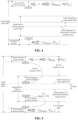
- FIG. 3 illustrates an optional processing flow of the method for determining resources for random access according to an embodiment of the present disclosure.
- the method for determining resources for random access may include operation S201.
- a terminal device with RedCap determines a second common PUCCH resource based on a frequency domain position of a first common PUCCH resource and a frequency offset.
- the second common PUCCH resource is a resource, for sending Hybrid Automatic Repeat Request (HARQ) feedback information, within a bandwidth corresponding to the terminal device with RedCap
- the first common PUCCH resource is a resource, for sending HARQ feedback information, corresponding to an initial uplink (UL) Bandwidth Part (BWP).
- the first common PUCCH resource is configured to by the network device.
- the frequency offset includes a first frequency offset and a second frequency offset.
- the frequency offset may be configured by a network device, or may also be determined according to a predefined rule. If the frequency offset is configured by the network device, the terminal device with RedCap can determine the frequency offset by receiving system information or an RRC signaling sent from the network device, i.e. the system information or the RRC signaling carries the frequency offset. For example, the network device indicates the frequency offset to the terminal device through the PUCCH-ConfigCommon or pucch-ResourceCommon information. If the frequency offset is configured by the network device, the network device can also determine the frequency offset according to a predefined rule, and then send the determined frequency offset to the terminal device with RedCap through system information or RRC signaling. If the network device does not send the frequency offset to the terminal device with RedCap through the system information or RRC signaling, the terminal device with RedCap may also determine the frequency offset according to a predefined rule.
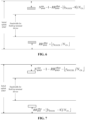
- the predefined rule may include that: the frequency offset is determined based on a relationship between the initial uplink BWP and the bandwidth corresponding to the terminal device with RedCap. If the first frequency offset included in the frequency offset is represented as RBooffset1 and the second frequency offset included in the frequency offset is represented as RBooffset2, a schematic diagram of a relationship between the initial UL BWP and the bandwidth corresponding to the terminal device with RedCap is shown in FIG. 4 . In FIG.
- the initial UL BWP is represented as BW1
- the bandwidth corresponding to the terminal device with RedCap is represented as BW2
- a difference between a center frequency of BW1 and a center frequency of BW2 is represented as CFoffset
- RBoffset1 (BW1-BW2)/2-CFoffset
- RBoffset2 (BW1-BW2)/2+CFoffset
- the first frequency offset is equal to a difference between half of a difference between the initial uplink BWP and the bandwidth for the terminal device with RedCap and a difference between a center frequency of the initial uplink BWP and a center frequency of the bandwidth for the terminal device with RedCap; and the second frequency offset is equal to a sum of half of the difference between the initial uplink BWP and the bandwidth for the terminal device with RedCap and the difference between the center frequency of the initial uplink BWP and the center frequency of the bandwidth for the terminal device with RedCap.
- FIG. 5 illustrates a schematic diagram of a relationship between a first PUCCH resource and a second PUCCH resource.
- a first frequency domain position of the second common PUCCH resource is obtained by adding the first frequency offset to a third frequency domain position of the first common PUCCH resource that is located in the initial uplink BWP; and a second frequency domain position of the second common PUCCH resource is obtained by subtracting the second frequency offset from a fourth frequency domain position of the first common PUCCH resource that is located in the initial uplink BWP.
- a frequency at the third frequency domain position is less than a frequency at the fourth frequency domain position.
- the resources used for a conventional terminal device e.g. a terminal device without RedCap
- the resources used for a conventional terminal device are located at the third frequency domain position and the fourth frequency domain position.
- the PRB of the resource, for sending HARQ feedback information, corresponding to the initial UL BWP is located at the third frequency domain position and the fourth frequency domain position as shown in FIG. 6
- an index of the PRB of the resource, for sending HARQ feedback information, corresponding to the initial UL BWP is increased from RB BWP offset or decreased from N BWP size ⁇ 1 ⁇ RB BWP offset .
- the second hopping of PUCCH and the first hopping of PUCCH are located at different frequency bands of the bandwidth of UL BWP. If the first hopping of PUCCH is located at the third frequency domain position, the second hopping of PUCCH is located at the fourth frequency domain position. According to FIG. 6 and FIG. 7 , in a case where the initial UL BWP is greater than the bandwidth for the terminal device with RedCap, the frequency resource of the first common PUCCH resource may not be within the bandwidth for the terminal device with RedCap.
- the center frequency of the initial UL BWP when aligned or very close to the center frequency of the bandwidth for the terminal device with RedCap, it may result in the terminal device with RedCap not having a common PUCCH resource available for transmitting HARQ feedback information.
- a first frequency domain position of the second common PUCCH resource is obtained by adding the first frequency offset to a third frequency domain position of the first common PUCCH resource that is located in the initial uplink BWP; and a second frequency domain position of the second common PUCCH resource is obtained by subtracting the second frequency offset from a fourth frequency domain position of the first common PUCCH resource that is located in the initial uplink BWP.
- the second common PUCCH resource for sending HARQ feedback information by the terminal device with RedCap is shifted to the center frequency of the initial LTL BWP on the basis of the first common PUCCH resource, so that the frequency resource of the second common PUCCH resource is located within the range of the bandwidth for the terminal device with RedCap.
- PRB index of a first hopping for the PUCCH tramsmission is RB BWP offset + ⁇ ⁇ PDCCH N CS ⁇ + RBoffset 1
- a PRB index of a second hopping is N BWP size ⁇ 1 ⁇ RB BWP offset ⁇ ⁇ ⁇ PDCCH N CS ⁇ ⁇ RBoffset 2
- N CS represents the number of indexes in a set of initial cyclic shift (CS) indexes
- an index of the initial cyclic shift is ⁇ PUCCH mod N CS
- N BWP size represents the number of PRBs included in the initial uplink BWP.
- the PRB index of the first hopping for the PUCCH transmission is N BWP size ⁇ 1 ⁇ RB BWP offset ⁇ ⁇ ⁇ PDCCH ⁇ 8 N CS ⁇ ⁇ RBoffset 2
- the PRB index of the second hopping is RB BWP offset + ⁇ ⁇ PDCCH ⁇ 8 N CS ⁇ + RBoffset 1
- N CS represents the number of indexes in a set of initial cyclic shift (CS) indexes
- an index of the initial cyclic shift is ( ⁇ PUCCH - 8)mod N CS
- N BWP size represents the number of PRBs included in the initial uplink BWP.
- the initial UL BWP includes the bandwidth for the terminal device with RedCap.
- the second common PUCCH resource used for sending HARQ feedback information by the terminal device with RedCap is shifted to the center frequency of the initial LTL BWP on the basis of the first common PUCCH resource, for sending HARQ feedback information, corresponding to the initial UL BWP, so that the frequency resource of the second common PUCCH resource is located within the range of the bandwidth for the terminal device with RedCap, and thus an effective second common PUCCH resource for sending the HARQ feedback information is configured for the terminal device with RedCap.
- FIG. 9 illustrates another optional process flow of the method for determining resources for random access according to an embodiment of the present disclosure, which may include the following operation S301.
- a terminal device with RedCap determines a second common PUCCH resource based on configuration information of a first common PUCCH resource and a bandwidth for the terminal device with RedCap.
- the second common PUCCH resource is a resource, for sending HARQ feedback information, within the bandwidth for the terminal device with RedCap
- the first common PUCCH resource is a resource, for sending HARQ feedback information, corresponding to an initial uplink BWP.
- a PRB index of the second common PUCCH resource is determined based on the number of PRBs N BWP ⁇ r SIZE included in the bandwidth for the terminal device with RedCap and a PRB offset RB BWP offset in the configuration information of the first common PUCCH resource.
- a PRB index of the second common PUCCH resource is a PRB index within the bandwidth for the terminal device with RedCap, and the PRB index has a range from 0 to N BWP ⁇ r SIZE ⁇ 1 , where N BWP ⁇ r SIZE represents the number of PRBs included in the bandwidth for the terminal device with RedCap.
- a PRB index of a first hopping for the PUCCH transmission is RB BWP offset + ⁇ ⁇ PDCCH N CS ⁇ ; and a PRB index of a second hopping for the PUCCH transmission is N BWP ⁇ r size ⁇ 1 ⁇ RB BWP offset ⁇ ⁇ ⁇ PDCCH N CS ⁇ ⁇ ⁇ PUCCH represents an index of a resource for sending the HARQ feedback information by the terminal device with RedCap, N CS represents the number of indexes in a set of initial CS indexes, RB BWP offset represents a PRB offset in configuration information of the first common PUCCH resource, N BWP ⁇ r SIZE represents the number of PRBs included in the bandwidth for the terminal device with RedCap, and an index of the initial cyclic shift is ⁇ PUCCH mod N CS .
- the PRB index of the first hopping for the PUCCH transmission is B BWP ⁇ r size ⁇ 1 ⁇ RB BWP offset ⁇ ⁇ ⁇ PDCCH ⁇ 8 N CS ⁇
- N CS represents the number of indexes in a set of initial CS indexes
- RB BWP offset represents a PRB offset in configuration information of the first common PUCCH resource
- N BWP ⁇ r SIZE represents the number of PRBs included in the bandwidth for the terminal device
- an index of the initial cyclic shift is ( ⁇ PUCCH - 8)mod N CS .
- a network device configures PUCCH resource configuration information for a terminal device, PUCCH resource indicator(s) is indicated by DCI, and n CCE ,0 and N CCE are provided.
- N BWP ⁇ r SIZE represents the number of PRBs included in the bandwidth for the terminal device with RedCap
- N BWP ⁇ r SIZE represents the number of PRBs included in the initial UL BWP.
- a method similar to the method for determining the PRB index is adopted, and a schematic diagram of a second common PUCCH resource determined by a terminal device with RedCap and a first common PUCCH resource determined by a terminal device without RedCap.
- the frequency domain positions of the second common PUCCH resources that are determined by the terminal device with RedCap based on the number of PRBs N BWP ⁇ r SIZE included in the bandwidth for the terminal device with RedCap are all within the bandwidth for the terminal device with RedCap.
- the frequency domain positions of the first common PUCCH resources that are determined by the terminal device without RedCap based on the number of PRBs N BWP SIZE included in the initial UL BWP are all within the initial UL BWP.
- the initial UL BWP includes the bandwidth for the terminal device with RedCap.
- the second common PUCCH resource can be determined based on the N BWP ⁇ r SIZE representing the number of PRBs included in the bandwidth for the terminal device with RedCap, so that the second common PUCCH resource configured by the network device can be included in the bandwidth for the terminal device with RedCap, and thus the terminal device with RedCap sends the HARQ feedback information through the second common PUCCH resource in the random access procedure.
- FIG. 11 illustrates another optional process flow of the method for determining resources for random access according to an embodiment of the present disclosure, which may include the following operation S401.
- the network device determines a second common PUCCH resource based on a frequency domain position of a first common PUCCH resource and a frequency offset.
- the second common PUCCH resource is a resource, for sending HARQ feedback information, within a bandwidth for a terminal device with RedCap
- the first common PUCCH resource is a resource, for sending HARQ feedback information, corresponding to an initial uplink BWP.
- the first common PUCCH resource is configured by the network device.
- the frequency offset includes a first frequency offset and a second frequency offset.
- the network device may determine the frequency offset according to a predefined rule and then send the determined frequency offset to the terminal device with RedCap through system information or RRC signaling. If the network device does not send the frequency offset to the terminal device with RedCap through the system information or the RRC signaling, the terminal device with RedCap may also determine the frequency offset according to a predefined rule.
- the process of determining the frequency offset by the network device according to the predefined rule is the same as the process of determining the frequency offset by the terminal device with RedCap according to the predefined rule in the above operation S201, which will not be elaborated herein.
- the method may further include operation S402.
- the network device sends system information or an RRC signaling, where the system information or the RRC signaling carries the frequency offset.
- the network device sends a frequency offset to the terminal device with RedCap through the system information or the RRC signaling, so that the terminal device determines the second PUCCH resource based on a frequency domain position of a first common PUCCH resource and a frequency offset.
- FIG. 12 illustrates another optional process flow of the method for determining resources for random access according to an embodiment of the present disclosure, which may include operation S501.
- a network device determines a second common PUCCH resource based on configuration information of a first common PUCCH resource and a bandwidth for a terminal device with RedCap.
- the second common PUCCH resource is a resource, for sending HARQ feedback information, within the bandwidth for the terminal device with RedCap
- the first common PUCCH resource is a resource, for sending HARQ feedback information, corresponding to an initial uplink BWP.
- the initial UL BWP includes the bandwidth for the terminal device with RedCap.
- a PRB index of the second common PUCCH resource is determined based on the number of PRBs N BWP ⁇ r SIZE included in the bandwidth for the terminal device with RedCap and a PRB offset RB BWP offset in the configuration information of the first common PUCCH resource.
- a PRB index of the second common PUCCH resource is a PRB index within the bandwidth for the terminal device with RedCap, and the PRB index has a range from 0 to N BWP ⁇ r SIZE ⁇ 1 , where N BWP ⁇ r SIZE represents the number of PRBs included in the bandwidth for the terminal device with RedCap.
- a PRB index of a first hopping of the PUCCH transmission is RB BWP offset + ⁇ ⁇ PDCCH N CS ⁇ ; and a PRB index of a second hopping of the PUCCH transmission is N BWP ⁇ r size ⁇ 1 ⁇ RB BWP offset ⁇ ⁇ ⁇ PDCCH N CS ⁇ ⁇ ⁇ PUCCH represents an index of a resource for sending the HARQ feedback information by the terminal device with RedCap, N CS represents the number of indexes in a set of initial CS indexes, RB BWP offset represents a PRB offset in configuration information of the first common PUCCH resource, N BWP ⁇ r SIZE represents the number of PRBs included in the bandwidth for the terminal device, and an index of the initial cyclic shift is ⁇ PUCCH mod N CS .
- the PRB index of the first hopping of the PUCCH transmission is N BWP ⁇ r size ⁇ 1 ⁇ RB BWP offset ⁇ ⁇ ⁇ PDCCH ⁇ 8 N CS ⁇
- N CS represents the number of indexes in a set of initial CS indexes
- RB BWP offset represents a PRB offset in configuration information of the first common PUCCH resource
- N BWP ⁇ r SIZE represents the number of PRBs included in the bandwidth for the terminal device
- an index of the initial cyclic shift is ( ⁇ PUCCH - 8)mod N CS .
- a network device configures the PUCCH resource configuration information for the terminal device, PUCCH resource indicator(s) is indicated by DCI, n CCE,0 and N CCE are provided.
- N BWP ⁇ r SIZE represents the number of PRBs in cluded in the bandwidth for the terminal device with RedCap, and N BWP SIZE represents the number of PRBs included in the initial UL BWP.
- a method similar to the method for determining the PRB index is adopted, and a schematic diagram of a second common PUCCH resource determined by a terminal device with RedCap and a first common PUCCH resource determined by a terminal device without RedCap is shown in FIG. 10 .
- the frequency domain positions of the second common PUCCH resources that are determined by the terminal device with RedCap based on the number of PRBs B BWP ⁇ r SIZE included in the bandwidth for the terminal device with RedCap are all within the bandwidth for the terminal device with RedCap.
- the frequency domain positions of the first common PUCCH resources that are determined by the terminal device without RedCap based on the number of PRBs N BWP SIZE included in the initial UL BWP are all within the initial UL BWP.
- the network device may also separately configure configuration information of second common PUCCH resource within the bandwidth corresponding to the terminal device with RedCap for the terminal device with RedCap, for example, the network device separately configures pucch-ResourceCommon information for the terminal device with RedCap, and RB BWP offset and N CS included in the pucch-ResourceCommon information are used separately for the terminal device with RedCap.
- the parameters in the configuration information of the second common PUCCH resource and the parameters in the configuration information of the first common PUCCH resource corresponding to the initial uplink BWP configured by the network device may be identical or different.
- N BWP ⁇ r SIZE may be the number of PRBs of the initial uplink BWP configured separately for the terminal device with RedCap, and correspondingly, the bandwidth corresponding to the terminal device with RedCap may be the initial uplink BWP configured by the network device for the terminal device with RedCap
- the embodiment of the present disclosure also provides a terminal device.
- the optional composition structure of the terminal device 600 includes a first processing unit 601.
- the first processing unit 601 is configured to determine a second common PUCCH resource based on a frequency domain position of a first common PUCCH resource and a frequency offset.
- the second common PUCCH resource is a resource, for sending HARQ feedback information, within a bandwidth for the terminal device with RedCap
- the first common PUCCH resource is a resource, for sending HARQ feedback information, corresponding to an initial uplink BWP.
- the frequency offset includes a first frequency offset and a second frequency offset.
- the frequency offset is configured by a network device through system information; or the frequency offset is configured by the network device through an RRC signaling.
- the terminal device 600 may further include a first receiving unit 602 configured to receive the system information or RRC signaling sent from the network device.
- the frequency offset is determined according to a predefined rule.
- the predefined rule includes that: the frequency offset is determined based on a relationship between the initial uplink BWP and the bandwidth for the terminal device with RedCap.
- the frequency offset includes a first frequency offset and a second frequency offset.
- the first frequency offset is equal to a difference between half of a difference between the initial uplink BWP and the bandwidth for the terminal device with RedCap and a difference between a center frequency of the initial uplink BWP and a center frequency of the bandwidth for the terminal device with RedCap.
- the second frequency offset is equal to a sum of half of the difference between the initial uplink BWP and the bandwidth for the terminal device with RedCap and the difference between the center frequency of the initial uplink BWP and the center frequency of the bandwidth for the terminal device with RedCap.
- a first frequency domain position of the second common PUCCH resource is obtained by adding the first frequency offset to a third frequency domain position of the first common PUCCH resource that is located in the initial uplink BWP.
- a second frequency domain position of the second common PUCCH resource is obtained by subtracting the second frequency offset from a fourth frequency domain position of the first common PUCCH resource that is located in the initial uplink BWP.
- the frequency at the third frequency domain position is less than a frequency at the fourth frequency domain position.
- a PRB index of a first hopping of the second common PUCCH resource is: RB BWP offset + ⁇ ⁇ PDCCH N CS ⁇ + RBoffset 1 .
- the PRB index of a second hopping of the second common PUCCH resource is: N BWP size ⁇ 1 ⁇ RB BWP offset ⁇ ⁇ ⁇ PDCCH N CS ⁇ ⁇ RBoffset 2 .
- ⁇ PUCCH represents an index of a resource for sending the HARQ feedback information by the terminal device with RedCap
- N CS represents the number of indexes in a set of initial cyclic shift (CS) indexes
- N BWP size represents the number of PRBs included in the initial uplink BWP
- RB BWP offset represents a PRB offset in configuration information of the first common PUCCH resource
- RBoffset1 represents the first frequency offset
- RBoffset2 represents the second frequency offset.
- a PRB index of a first hopping of the second common PUCCH resource is: N BWP size ⁇ 1 ⁇ RB BWP offset ⁇ ⁇ ⁇ PDCCH ⁇ 8 N CS ⁇ ⁇ RBoffset 2 .
- the PRB index of a second hopping of the second common PUCCH resource is: RB BWP offset + ⁇ ⁇ PDCCH ⁇ 8 N CS ⁇ + RBoffset 1 .
- ⁇ PUCCH represents an index of a resource for sending the HARQ feedback information by the terminal device with RedCap
- N CS represents the number of indexes in a set of initial cyclic shift (CS) indexes
- N BWP size represents the number of PRBs included in the initial uplink BWP
- RB BWP offset represents a PRB offset in configuration information of the first common PUCCH resource
- RBoffset1 represents the first frequency offset
- RBoffset 2 represents the second frequency offset.
- the initial uplink BWP includes the bandwidth for the terminal device with RedCap.
- inventions of the present disclosure also provide another terminal device.
- the optional composition structure of the terminal device 800 includes a second processing unit 801.
- the second processing unit 801 is configured to determine a second common PUCCH resource based on configuration information of a first common PUCCH resource and a bandwidth for the terminal device with RedCap.
- the second common PUCCH resource is a resource, for sending HARQ feedback information, within the bandwidth for a terminal device with RedCap
- the first common PUCCH resource is a resource, for sending HARQ feedback information, corresponding to an initial uplink BWP.
- a PRB index of the second common PUCCH resource is determined based on the number of PRBs included in the bandwidth for the terminal device with RedCap and a PRB offset in the configuration information of the first common PUCCH resource.
- a PRB index of the second common PUCCH resource is a PRB index within the bandwidth for the terminal device with RedCap, and the PRB index has a range from 0 to N BWP ⁇ r SIZE ⁇ 1 , where N BWP ⁇ r SIZE represents the number of PRBs included in the bandwidth for the terminal device with RedCap.
- a PRB index of a first hopping of the second common PUCCH resource is: RB BWP offset + ⁇ ⁇ PDCCH N CS ⁇ .
- the PRB index of a second hopping of the second common PUCCH resource is: N BWP ⁇ r size ⁇ 1 ⁇ RB BWP offset ⁇ ⁇ ⁇ PDCCH N CS ⁇ .
- ⁇ PUCCH represents an index of a resource for sending the HARQ feedback information by the terminal device with RedCap
- N CS represents the number of indexes in a set of initial CS indexes
- RB BWP offset represents a PRB offset in configuration information of the first common PUCCH resource
- N BWP ⁇ r SIZE represents the number of PRBs included in the bandwidth for the terminal device with RedCap.
- a PRB index of a first hopping of the second common PUCCH resource is: N BWP ⁇ r size ⁇ 1 ⁇ RB BWP offset ⁇ ⁇ ⁇ PDCCH ⁇ 8 N CS ⁇ .
- the PRB index of a second hopping of the second common PUCCH resource is: RB BWP offset + ⁇ ⁇ PDCCH ⁇ 8 N CS ⁇ .
- ⁇ PUCCH represents an index of a resource for sending the HARQ feedback information by the terminal device with RedCap
- N CS represents the number of indexes in a set of initial CS indexes
- RB BWP offset represents a PRB offset in configuration information of the first common PUCCH resource
- N BWP ⁇ r SIZE represents the number of PRBs included in the bandwidth for the terminal device with RedCap.
- the initial uplink BWP includes the bandwidth for the terminal device with RedCap.
- inventions of the present disclosure also provide a network device.
- the optional composition structure of the network device 900 includes a third processing unit 901.
- the third processing unit 901 is configured to determine a second common PUCCH resource based on a frequency domain position of a first common PUCCH resource and a frequency offset.
- the second common PUCCH resource is a resource, for sending HARQ feedback information, within a bandwidth for a terminal device with RedCap
- the first common PUCCH resource is a resource, for sending HARQ feedback information, corresponding to an initial uplink BWP.
- the frequency offset includes a first frequency offset and a second frequency offset.
- the network device 900 further includes a first sending unit 902.
- the first sending unit 902 is configured to send system information or an RRC signaling, where the system information or the RRC signaling carries the frequency offset.
- the frequency offset is determined according to a predefined rule.
- the predefined rule includes that: the frequency offset is determined based on a relationship between the initial uplink BWP and the bandwidth for the terminal device with RedCap.
- the frequency offset includes a first frequency offset and a second frequency offset.
- the first frequency offset is equal to a difference between half of a difference between the initial uplink BWP and the bandwidth for the terminal device with RedCap and a difference between a center frequency of the initial uplink BWP and a center frequency of the bandwidth for the terminal device with RedCap.
- the second frequency offset is equal to a sum of half of the difference between the initial uplink BWP and the bandwidth for the terminal device with RedCap and the difference between the center frequency of the initial uplink BWP and the center frequency of the bandwidth for the terminal device with RedCap.
- a first frequency domain position of the second common PUCCH resource is obtained by adding the first frequency offset to a third frequency domain position of the first common PUCCH resource that is located in the initial uplink BWP.
- a second frequency domain position of the second common PUCCH resource is obtained by subtracting the second frequency offset from a fourth frequency domain position of the first common PUCCH resource that is located in the initial uplink BWP.
- the frequency of at the third frequency domain position is less than a frequency of at the fourth frequency domain position.
- a PRB index of a first hopping of the second common PUCCH resource is: RB BWP offset + ⁇ ⁇ PDCCH N CS ⁇ + RBoffset 1 .
- the PRB index of a second hopping of the second common PUCCH resource is: N BWP size ⁇ 1 ⁇ RB BWP offset ⁇ ⁇ ⁇ PDCCH N CS ⁇ ⁇ RBoffset 2 .
- ⁇ PUCCH represents an index of a resource for sending the HARQ feedback information by the terminal device with RedCap
- N CS represents the number of indexes in a set of initial cyclic shift (CS) indexes
- N BWP size represents the number of PRBs included in the initial uplink BWP
- RB BWP offset represents a PRB offset in configuration information of the first common PUCCH resource
- RBoffset1 represents the first frequency offset
- RBoffset2 represents the second frequency offset.
- a PRB index of a first hopping of the second common PUCCH resource is: N BWP size ⁇ 1 ⁇ RB BWP offset ⁇ ⁇ ⁇ PDCCH ⁇ 8 N CS ⁇ ⁇ RBoffset 2 .
- the PRB index of a second hopping of the second common PUCCH resource is: RB BWP offset + ⁇ ⁇ PDCCH ⁇ 8 N CS ⁇ + RBoffset 1 .
- ⁇ PUCCH represents an index of a resource for sending the HARQ feedback information by the terminal device with RedCap
- N CS represents the number of indexes in a set of initial cyclic shift (CS) indexes
- N BWP size represents the number of PRBs included in the initial uplink BWP
- RB BWP offset represents a PRB offset in configuration information of the first common PUCCH resource
- RBoffset1 represents the first frequency offset
- RBoffset2 represents the second frequency offset.
- the initial uplink BWP includes the bandwidth for the terminal device with RedCap.
- inventions of the present disclosure also provide another network device.
- the optional composition structure of the network device 1000 includes a fourth processing unit 1001.
- the fourth processing unit 1001 is configured to determine a second common PUCCH resource based on configuration information of a first common PUCCH resource and a bandwidth for a terminal device with RedCap.
- the second common PUCCH resource is a resource, for sending HARQ feedback information, within the bandwidth for the terminal device with RedCap
- the first common PUCCH resource is a resource, for sending HARQ feedback information, corresponding to an initial uplink BWP.
- a PRB index of the second common PUCCH resource is determined based on the number of PRBs included in the bandwidth for the terminal device with RedCap and a PRB offset in the configuration information of the first common PUCCH resource.
- a PRB index of the second common PUCCH resource is a PRB index within the bandwidth for the terminal device with RedCap, and the PRB index has a range from 0 to N BWP ⁇ r SIZE ⁇ 1 , where N BWP ⁇ r SIZE represents the number of PRBs included in the bandwidth for the terminal device with RedCap.
- a PRB index of a first hopping of the second common PUCCH resource is: RB BWP offset + ⁇ ⁇ PDCCH N CS ⁇ .
- the PRB index of a second hopping of the second common PUCCH resource is: N BWP ⁇ r size ⁇ 1 ⁇ RB BWP offset ⁇ ⁇ ⁇ PDCCH N CS ⁇ .
- ⁇ PUCCH represents an index of a resource for sending the HARQ feedback information by the terminal device with RedCap
- N CS represents the number of indexes in a set of initial CS indexes
- an index of the initial cyclic shift is PUCCH mod ( N CS )
- N BWP ⁇ r SIZE represents the number of PRBs included in the bandwidth for the terminal device with RedCap.
- a PRB index of a first hopping of the second common PUCCH resource is: N BWP ⁇ r size ⁇ 1 ⁇ RB BWP offset ⁇ ⁇ ⁇ PDCCH ⁇ 8 N CS ⁇ .
- the PRB index of a second hopping of the second common PUCCH resource is: RB BWP offset + ⁇ ⁇ PDCCH ⁇ 8 N CS ⁇ .
- ⁇ PUCCH represents an index of a resource for sending the HARQ feedback information by the terminal device with RedCap
- N CS represents the number of indexes in a set of initial CS indexes
- an index of the initial cyclic shift is ( ⁇ PUCCH - 8)mod N CS
- N BWP ⁇ r SIZE represents the number of PRBs included in the bandwidth for the terminal device with RedCap.
- the initial uplink BWP includes the bandwidth for the terminal device with RedCap.
- each of the first processing unit 601, the second processing unit 801, the third processing unit 901 and the fourth processing unit 1001 can be implemented by a processor
- the functions of the first sending unit 902 can be implemented by a transmitter or transceiver
- the functions of the first receiving unit 602 can be implemented by a receiver or transceiver.
- Embodiments of the present disclosure also provide a terminal device, including a processor and a memory configured to store computer programs capable of running on the processor.
- the processor is configured to implement, when running the computer programs, the operations of the method for determining resources for random access performed by the terminal device as described above.
- Embodiments of the present disclosure also provide a network device, including a processor and a memory configured to store computer programs capable of running on the processor.
- the processor is configured to implement, when running the computer programs, the operations of the method for determining resources for random access performed by the network device as described above.
- Embodiments of the present disclosure also provide a chip including a processor configured to invoke and run computer programs from a memory, to cause a device installed with the chip to perform the method for determining resources for random access performed by the terminal device as described above.
- Embodiments of the present disclosure also provide a chip including a processor configured to invoke and run computer programs from a memory, to cause a device installed with the chip to perform the method for determining resources for random access performed by the network device as described above.
- Embodiments of the present disclosure also provide a storage medium having stored thereon executable programs that, when executed by a processor, cause the processor to implement the method for determining resources for random access performed by the terminal device as described above.
- Embodiments of the present disclosure also provide a storage medium having stored thereon executable programs that, when executed by a processor, cause the processor to implement the method for determining resources for random access performed by the network device as described above.
- Embodiments of the present disclosure also provide a computer program product including computer program instructions.
- the computer program instructions cause a computer to perform the method for determining resources for random access performed by the terminal device as described above.
- Embodiments of the present disclosure also provide a computer program product including computer program instructions.
- the computer program instructions cause a computer to perform the method for determining resources for random access performed by the network device as described above.
- Embodiments of the present disclosure also provide a computer program causing a computer to perform the method for determining resources for random access performed by the terminal device as described above.
- Embodiments of the disclosure also provide a computer program causing a computer to perform the method for determining resources for random access performed by the network device as described above.
- FIG. 17 is a schematic diagram of a hardware structure of an electronic device (terminal device or network device) according to an embodiment of the present disclosure.
- the electronic device 700 includes at least one processor 701, a memory 702 and at least one network interface 704.
- Various components in the electronic device 700 are coupled together by a bus system 705. It can be understood that the bus system 705 is used for implementing connection communications between these components.
- the bus system 705 includes a power bus, a control bus and a status signal bus in addition to a data bus. However, for clarity, all the buses are designated as bus system 705 in FIG. 17 .
- the memory 702 may be a volatile memory or non-volatile memory, or may also include both volatile and non-volatile memory.
- the non-volatile memory can be Read-Only Memory (ROM), Programmable Read-Only Memory (PROM), Erasable Programmable Read-Only Memory (EPROM), Electrically Erasable Programmable Read-Only Memory (EEPROM), Ferromagnetic Random Access Memory (FRAM), Flash Memory, magnetic surface memory, Optical Disk, or Compact Disc Read ad-Only Memory (CD-ROM).
- the magnetic surface memory may be a magnetic disk memory or a magnetic tape memory.
- the volatile memory may be Random Access Memory (RAM) which serves as an external cache.
- RAM Random Access Memory
- SRAM Static Random Access Memory
- SSRAM Synchronous Static Random Access Memory
- DRAM Dynamic Random Access Memory
- SDRAM Synchronous Dynamic Random Access Memory
- DDRSDRAM Double Data Rate Synchronous Dynamic Random Access Memory
- ESDRAM Enhanced Synchronous Dynamic Random Access Memory
- SLDRAM SyncLink Dynamic Random Access Memory
- DRRAM Direct Rambus Random Access Memory
- the memory 702 in the embodiments of the present disclosure is configured to store various types of data to support the operations of the electronic device 700.
- Examples of such data include any computer program, such as application program 7022, for operating on the electronic device 700.
- the programs for implementing the method of the embodiments of the present disclosure may be included in the application program 7022.
- the methods disclosed in the above embodiments of the present disclosure may be applied to or implemented by the processor 701.
- the processor 701 may be an integrated circuit chip with signal processing capability. In the implementation process, each step of the above method embodiment can be completed by integrated logic circuit of hardware in the processor 701 or instructions in the form of software.
- the processor 701 can be a general-purpose processor, a digital signal processor (DSPS), or other programmable logic devices, discrete gate or transistor logic devices, and discrete hardware components.
- DSPS digital signal processor
- the disclosed methods, steps and logic block diagrams in the embodiments of the present disclosure can be implemented or executed by the processor 701.
- the general-purpose processor may be a microprocessor or any conventional processor or the like.
- the steps of the method disclosed in connection with the embodiments of the present disclosure can be directly embodied as completion of the execution of the hardware decoding processor, or by the combination of the hardware and software modules in the decoding processor.
- the software modules can be located storage media.
- the storage medium is located in the memory 702, and the processor 701 reads the information in the memory 702 and completes the steps of the above method in combination with its hardware.
- the electronic device 700 may be implemented by one or more Application Specific Integrated Circuits (ASICs), DSP, Programmable Logic Devices (PLDs), Complex Programmable Logic Devices (CPLDs), FPGAs, General Purpose Processors, Controllers, MCUs, MPUs, or other electronic components to perform the foregoing methods.
- ASICs Application Specific Integrated Circuits
- DSP Digital Signal processor
- PLDs Programmable Logic Devices
- CPLDs Complex Programmable Logic Devices
- FPGAs General Purpose Processors
- Controllers MCUs
- MPUs or other electronic components to perform the foregoing methods.
- a computer program instruction is configured to implement each flow and/or block in the flowcharts and/or block diagrams, and the combination of flows/blocks in the flowcharts and/or block diagrams.
- These computer program instructions may be provided to a universal computer, a special computer, an embedded processor or processors of other programmable data processing devices to generate a machine, such that an apparatus for implementing the functions specified in one or more flow in the flowcharts and/or one or more blocks in the block diagrams is generated through the instructions executed by the computer or the processor of other programmable data processing devices.
- These computer program instructions may also be stored in a computer readable memory that can direct the computer or other programmable data processing devices to work in a particular manner such that the instruction stored in the computer readable memory generates a product including an instruction apparatus, which implements the functions specified in one or more flows in the flowchart and/or one or more blocks in the block diagram.
- These computer program instructions may also be loaded in a computer or other programmable data processing devices such that a series of operation steps are executed on the computer or other programmable data processing devices to generate computer implemented processing, and thus the instruction executed on the computer or other programmable data processing devices provides the operations for implementing the functions specified in one or more flows in the flowchart and/or one or more blocks in the block diagram.
- system and “network” in the disclosure may usually be exchanged in the disclosure.
- term “and/or” is only an association relationship describing associated objects and represents that three relationships may exist.
- a and/or B may represent three conditions: i.e., independent existence of A, existence of both A and B and independent existence of B.
- character "/" in the disclosure usually represents that previous and next associated objects form an "or" relationship.
Landscapes
- Engineering & Computer Science (AREA)
- Signal Processing (AREA)
- Computer Networks & Wireless Communication (AREA)
- Mobile Radio Communication Systems (AREA)
Abstract
Description
- The disclosure relates to the technical field of wireless communications, and in particular to, methods for determining resources for random access, an electronic device and a storage medium.
- In a New Radio (NR) system, a terminal device with Reduced Capability (RedCap) having characteristics of low complexity, low cost and low capability is introduced. Thus, How to allocate efficient resources for random access for the terminal device with RedCap is a goal that has been pursued all the time.
- Embodiments of the disclosure provide methods for determining resources for random access, an electronic device and a storage medium, which can clearly define the opportunity when the terminal device receives a paging message.
- In a first aspect, embodiments of the present disclosure provide a method for determining resources for random access, which includes the following operation. A terminal device with RedCap determines a second common Physical Uplink Control Channel (PUCCH) resource based on a frequency domain position of a first common PUCCH resource and a frequency offset.
- The second common PUCCH resource is a resource, for sending Hybrid Automatic Repeat Request (HARQ) feedback information, within a bandwidth for the terminal device with RedCap, and the first common PUCCH resource is a resource, for sending HARQ feedback information, corresponding to an initial uplink Bandwidth Part (BWP).
- In a second aspect, embodiments of the present disclosure provide a method for determining resources for random access, which includes the following operation. A terminal device with RedCap determines a second common PUCCH resource based on configuration information of a first common PUCCH resource and a bandwidth for the terminal device with RedCap.
- The second common PUCCH resource is a resource, for sending HARQ feedback information, within the bandwidth for the terminal device with RedCap, and the first common PUCCH resource is a resource, for sending HARQ feedback information, corresponding to an initial uplink BWP.
- In a third aspect, embodiments of the present disclosure provide a method for determining resources for random access, which includes the following operation.
- A network device determines a second common PUCCH resource based on a frequency domain position of a first common PUCCH resource and a frequency offset.
- The second common PUCCH resource is a resource, for sending HARQ feedback information, within a bandwidth for a terminal device with RedCap, and the first common PUCCH resource is a resource, for sending HARQ feedback information, corresponding to an initial uplink BWP.
- In a fourth aspect, embodiments of the present disclosure provide a method for determining resources for random access, which includes the following operation.
- A network device determines a second common PUCCH resource based on configuration information of a first common PUCCH resource and a bandwidth for terminal device with RedCap.
- The second common PUCCH resource is a resource, for sending HARQ feedback information, within the bandwidth for the terminal device with RedCap, and the first common PUCCH resource is a resource, for sending HARQ feedback information, corresponding to an initial uplink BWP.
- In a fifth aspect, embodiments of the present disclosure provide a terminal device. The terminal device is a terminal device with RedCap, and the terminal device includes a first processing unit.
- The first processing unit is configured to determine a second common PUCCH resource based on a frequency domain position of a first common PUCCH resource and a frequency offset.
- The second common PUCCH resource is a resource, for sending HARQ feedback information, within a bandwidth for the terminal device with RedCap, and the first common PUCCH resource is a resource, for sending HARQ feedback information, corresponding to an initial uplink BWP.
- In a sixth aspect, embodiments of the present disclosure provide a terminal device. The terminal device is terminal device with RedCap, and the terminal device includes a second processing unit.
- The second processing unit is configured to determine a second common PUCCH resource based on configuration information of a first common PUCCH resource and a bandwidth for the terminal device with RedCap.
- The second common PUCCH resource is a resource, for sending HARQ feedback information, within the bandwidth for the terminal device with RedCap, and the first common PUCCH resource is a resource, for sending HARQ feedback information, corresponding to an initial uplink BWP.
- In a seventh aspect, embodiments of the present disclosure provide a network device. The network device includes a third processing unit configured to determine a second common PUCCH resource based on a frequency domain position of a first common PUCCH resource and a frequency offset.
- The second common PUCCH resource is a resource, for sending HARQ feedback information, within a bandwidth for a terminal device with RedCap, and the first common PUCCH resource is a resource, for sending HARQ feedback information, corresponding to an initial uplink BWP.
- In an eighth aspect, embodiments of the present disclosure provide a network device including a fourth processing unit.
- The fourth processing unit is configured to determine a second common PUCCH resource based on configuration information of a first common PUCCH resource and a bandwidth for a terminal device with RedCap.
- The second common PUCCH resource is a resource, for sending HARQ feedback information, within the bandwidth for the terminal device with RedCap, and the first common PUCCH resource is a resource, for sending HARQ feedback information, corresponding to an initial uplink BWP.
- In a ninth aspect, embodiments of the present disclosure provide a terminal device including a processor and a memory configured to store computer programs capable of running on the processor. The processor is configured to implement, when running the computer programs, the operations of the method for determining resources for random access performed by the terminal device as described above.
- In a tenth aspect, embodiments of the present disclosure provide a network device including a processor and a memory configured to store computer programs capable of running on the processor. The processor is configured to implement, when running the computer programs, the operations of the method for determining resources for random access performed by the network device as described above.
- In an eleventh aspect, embodiments of the present disclosure provide a chip including a processor configured to invoke and run computer programs from a memory, to cause a device installed with the chip to perform the method for determining resources for random access performed by the terminal device as described above.
- In a twelfth aspect, embodiments of the present disclosure provide a chip including a processor configured to invoke and run computer programs from a memory, to cause a device installed with the chip to perform the method for determining resources for random access performed by the network device as described above.
- In a thirteenth aspect, embodiments of the present disclosure provide a storage medium having stored thereon executable programs that, when executed by a processor, cause the processor to implement the method for determining resources for random access performed by the terminal device as described above.
- In a fourteenth aspect, embodiments of the present disclosure provide a storage medium having stored thereon executable programs that, when executed by a processor, cause the processor to implement the method for determining resources for random access performed by the network device as described above.
- In a fifteenth aspect, embodiments of the present disclosure provide a computer program product including computer program instructions. The computer program instructions cause a computer to perform the method for determining resources for random access performed by the terminal device as described above.
- In a sixteenth aspect, embodiments of the present disclosure provide a computer program product including computer program instructions. The computer program instructions cause a computer to perform the method for determining resources for random access performed by the network device as described above.
- In a seventeenth aspect, embodiments of the present disclosure provide a computer program causing a computer to perform the method for determining resources for random access performed by the terminal device as described above.
- In an eighteenth aspect, embodiments of the present disclosure provide a computer program causing a computer to perform the method for determining resources for random access performed by the network device as described above.
-
-
FIG. 1 is a schematic diagram of a random access procedure according to an embodiment of the present disclosure. -
FIG. 2 is a schematic diagram of a composition structure of a communication system according to an embodiment of the present disclosure. -
FIG. 3 is a schematic diagram of an optional processing flow of a method for determining resources for random access according to an embodiment of the present disclosure. -
FIG. 4 is a schematic diagram of a relationship between an initial UL BWP and a bandwidth for a terminal device with RedCap according to an embodiment of the present disclosure. -
FIG. 5 is a schematic diagram of a relationship between a first PUCCH resource and a second PUCCH resource according to an embodiment of the present disclosure. -
FIG. 6 is a schematic diagram of a Physical Resource Block (PRB) index of a first hopping of PUCCH according to an embodiment of the present disclosure. -
FIG. 7 is a schematic diagram of a PRB index of a second hopping of PUCCH according to an embodiment of the present disclosure. -
FIG. 8 is a schematic diagram of a second PUCCH resource according to an embodiment of the present disclosure. -
FIG. 9 is a schematic diagram of another optional process flow of a method for determining resources for random access according to an embodiment of the present disclosure. -
FIG. 10 is a schematic diagram of a first common PUCCH resource determined by a terminal device with RedCap and a second common PUCCH resource determined by a terminal device without RedCap according to an embodiment of the present disclosure. -
FIG. 11 is a schematic diagram of an optional process flow of a method for determining resources for random access according to an embodiment of the present disclosure. -
FIG. 12 is a schematic diagram of another optional process flow of a method for determining resources for random access according to an embodiment of the present disclosure. -
FIG. 13 is a schematic diagram of an optional composition structure of a terminal device according to an embodiment of the present disclosure. -
FIG. 14 is a schematic diagram of another optional composition structure of a terminal device according to an embodiment of the present disclosure. -
FIG. 15 is a schematic diagram of an optional composition structure of a network device according to an embodiment of the present disclosure. -
FIG. 16 is a schematic diagram of another optional composition structure of a network device according to an embodiment of the present disclosure. -
FIG. 17 is a schematic diagram of a hardware composition structure of an electronic device according to an embodiment of the present disclosure. - In order to enable a more detailed understanding of the features and technical content of the embodiments of the present disclosure, the implementation of the embodiments of the present disclosure will be described in detail below in conjunction with the accompanying drawings, which are provided for illustration only and are not intended to limit the embodiments of the present disclosure.
- Before describing the embodiments of the present disclosure, the related contents will be briefly explained.
- NR system can support Enhanced Mobile Broadband (eMBB) service to satisfy the needs of high speed, high spectrum efficiency and large bandwidth. In practical applications, besides the eMBB service, there are many different types of services, such as sensor network service, video surveillance service and wearable service. These types of services have different requirements from the eMBB service in terms of speed, bandwidth, power consumption and cost. Compared to terminal devices supporting eMBB, terminal devices supporting these services have reduced capability, such as reduced supported bandwidth, relaxed processing time and reduced number of antennas. Therefore, it is necessary to optimize the NR system for these services and the corresponding terminal devices with RedCap, and the optimized system is called NR-light system. In LTE technology, similar systems have been designed to support terminals with large number of connections, low power consumption and low cost, such as Machine Type Communication (MTC) and Narrow Band Internet of Thing (NB-IoT). In the NR system, it is desirable to introduce similar technologies to use NR technology to better support other types of services except the eMBB service. A terminal device supporting this kind of service has the characteristics of low complexity, low cost and low capability, which is called terminal device with RedCap or RedCap terminal device.
- Compared with the traditional NR terminal device, the terminal device with RedCap has the characteristics of low complexity and low cost, such as reduced receiving channels, reduced supported transmission bandwidth and so on. At present, NR terminal device needs to support at least two receiving channels, and NR terminal device in some frequency bands needs to support four receiving channels. Each receiving channel includes a receiving antenna, a filter, a power amplifier, an analog-to-digital sampler and other components. Therefore, reducing the number of RF channels required by NR terminal device will significantly reduce the cost of the terminal. In addition, traditional NR terminal device needs to support a wider transmission bandwidth. For example, for the frequency range FR1, NR terminal device needs to support a maximum bandwidth of 100MHz, and for the frequency range FR2, NR terminal device needs to support a maximum bandwidth of 400MHz. In order to reduce the cost of the terminal device with RedCap and reduce the power consumption of the terminal device with RedCap, the terminal device with RedCap can support a smaller transmission bandwidth, only a transmission bandwidth of 20MHz is supported for the frequency range FR1 and only a transmission bandwidth of 100MHz is supported for the frequency range FR2.
- In addition, the terminal device with RedCap may also have the characteristics of supporting lower peak rate, supporting looser processing latency, and larger processing latency.
- For a terminal device in the initial access stage, after receiving system information sent from the network device, the terminal device initiates a random access procedure and establishes a Radio Resource Control (RRC) connection with the network device. In the process of establishing the RRC connection, the terminal device needs to identify the type of the terminal device as the ordinary terminal device (terminal device without RedCap or non-RedCap terminal device) or terminal device with RedCap (RedCap terminal device), and acquire the capability information related to the terminal device. Specifically, the terminal device may indicate the type of the terminal device in any one of the following manners: 1) the type of the terminal device is indicated in the stage of sending Msg1, for example, the type of the terminal device is indicated through the initial UpLink (LTL) Bandwidth Part (BWP) where
Msg 1 is transmitted, through independent resources for Random Access Channel (RACH), or partitioning independent sets of random access preambles; 2) the type of the terminal device is indicated in the stage of sending Msg3, for example, the type of the terminal device is indicated in the payload of the Physical Uplink Shared Channel (PUSCH) carrying Msg 3; 3) the type of the terminal device is indicated after transmission of Msg4, such as the type of the terminal device is indicated by Msg5 or the type of the terminal device is reported as the capability of the terminal device; and 4) the type of the terminal device is indicated in the stage of sending MsgA in a 2-step random access. - The random access process is briefly described below. The schematic diagram of random access procedure in NR system, as shown in
FIG. 1 , adopts a four-step random access mode, including the following four steps. - In a first step, the terminal device sends a random access including a preamble(s) to the network device, i.e. the terminal device sends a message 1 (MSG1).
- In a second step, after the network device detects the preamble(s), the network device sends a Random Access Response (RAR) to the terminal device. That is, the network device sends MSG2. MSG2 carries PUSCH resources that can be used for sending MSG3 by the terminal device, a Radio Network Temporary Identity (RNTI) allocated for the terminal device, and a time advance command allocated for the terminal device.
- In a third step, the terminal device sends the MSG3 by using the PUSCH resources indicated by the RAR message, and the MSG3 carries the temporary identity information specific to the terminal device.
- In a fourth step, the network device sends the MSG4 to the terminal device. The MSG4 includes a contention resolution message. The network device allocates uplink transmission resources for the terminal device. After receiving the MSG4 sent from the network device, the terminal device will detect whether the temporary identity information specific to the terminal device sent by the terminal device in the MSG3 is included in the contention resolution message from the base station. If it is included, it indicates that the random access of the terminal device is successful, or otherwise it is considered that the random access of the terminal device fails, and the terminal device needs to initiate the random access procedure starting from the first step again.
- In the initial access stage of terminal device, for example in the random access procedure, it is necessary to send Hybrid Automatic Repeat Request (HARQ) feedback information for Msg4 or MsgB through a Physical Uplink Control Channel (PUCCH). Since there is no configuration of the PUCCH resource set dedicated to the terminal device at this time, a predefined manner is adopted. The predefined PUCCH resource set is only used for sending the HARQ feedback information, so each of the PUCCH resources in the predefined PUCCH resource set only needs to carry 1-2bit HARQ feedback information, that is, each of the PUCCH resources is only composed of PUCCH format 0 and
PUCCH format 1. The network device configures, through the System Information Block (SIB1), a common PUCCH resource set for all the terminal devices before the RRC is established. - The terminal device transmits the HARQ-ACK information at the initial UL BWP by using a PUCCH resource that is configured through pucch-ResourceCommon in PUCCH-ConfigCommon. The relevant signaling is as follows.
     PUCCH-ConfigCommon information element
     --ASN1START
     -- TAG-PUCCH-CONFIGCOMMON-START
     PUCCH-ConfigCommon :: = SEQUENCE {
     pucch-ResourceCommon INTEGER (0..15) OPTIONAL, -- Cond InitialBWP-Only
     pucch-GroupHopping ENUMERATED { neither, enable, disable },
     hoppingID INTEGER (0..1023) OPTIONAL, -- Need R
     p0-nominal INTEGER (-202..24) OPTIONAL, -- Need R
     ...
     }
| Index | PUCCH format | First symbol | Number of symbols | PRB offset  | Set of initial CS indexes |
| 0 | 0 | 12 | 2 | 0 | {0, 3} |
| 1 | 0 | 12 | 2 | 0 | {0, 4, 8} |
| 2 | 0 | 12 | 2 | 3 | {0, 4, 8} |
| 3 | 1 | 10 | 4 | 0 | {0, 6} |
| 4 | 1 | 10 | 4 | 0 | {0, 3, 6, 9} |
| 5 | 1 | 10 | 4 | 2 | {0, 3, 6, 9} |
| 6 | 1 | 10 | 4 | 4 | {0, 3, 6, 9} |
| 7 | 1 | 4 | 10 | 0 | {0, 6} |
| 8 | 1 | 4 | 10 | 0 | {0, 3, 6, 9} |
| 9 | 1 | 4 | 10 | 2 | {0, 3, 6, 9} |
| 10 | 1 | 4 | 10 | 4 | {0, 3, 6, 9} |
| 11 | 1 | 0 | 14 | 0 | {0, 6} |
| 12 | 1 | 0 | 14 | 0 | {0, 3, 6, 9} |
| 13 | 1 | 0 | 14 | 2 | {0, 3, 6, 9} |
| 14 | 1 | 0 | 14 | 4 | {0, 3, 6, 9} |
| 15 | 1 | 0 | 14 |  | {0, 3, 6, 9} |

where NCCE is the number of control channel elements (CCE) in a Control resource set (CORESET) of the PDCCH, nCCE,0 is an index of the first CCE of the received PDCCH in CORESET. Δ PRI is a value that is indicated by the PUCCH resource indicator domain in Downlink Control Information (DCI) with format 1_0 or format 1_1.











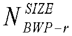




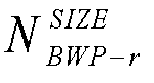


Claims (74)
- A method for determining resources for random access, comprising:determining, by a terminal device with reduced capability (RedCap), a second common Physical Uplink Control Channel (PUCCH) resource based on a frequency domain position of a first common PUCCH resource and a frequency offset,wherein the second common PUCCH resource is a resource, for sending Hybrid Automatic Repeat Request (HARQ) feedback information, within a bandwidth for the terminal device with RedCap, and the first common PUCCH resource is a resource, for sending HARQ feedback information, corresponding to an initial uplink bandwidth part (BWP).
- The method of claim 1, wherein the frequency offset comprises a first frequency offset and a second frequency offset.
- The method of claim 1 or 2, wherein the frequency offset is configured by a network device through system information; or
the frequency offset is configured by the network device through a Radio Resource Control (RRC) signaling. - The method of any one of claims 1 to 3, wherein the frequency offset is determined according to a predefined rule.
- The method of claim 4, wherein the predefined rule comprises that:
the frequency offset is determined based on a relationship between the initial uplink BWP and the bandwidth for the terminal device with RedCap. - The method of any one of claims 1 to 5, wherein the frequency offset comprises a first frequency offset and a second frequency offset,the first frequency offset is equal to a difference between half of a difference between the initial uplink BWP and the bandwidth for the terminal device with RedCap and a difference between a center frequency of the initial uplink BWP and a center frequency of the bandwidth for the terminal device with RedCap; andthe second frequency offset is equal to a sum of half of the difference between the initial uplink BWP and the bandwidth for the terminal device with RedCap and the difference between the center frequency of the initial uplink BWP and the center frequency of the bandwidth for the terminal device with RedCap.
- The method of any one of claims 1 to 6, whereina first frequency domain position of the second common PUCCH resource is obtained by adding the first frequency offset to a third frequency domain position of the first common PUCCH resource that is located in the initial uplink BWP;a second frequency domain position of the second common PUCCH resource is obtained by subtracting the second frequency offset from a fourth frequency domain position of the first common PUCCH resource that is located in the initial uplink BWP, anda frequency at the third frequency domain position is less than a frequency at the fourth frequency domain position.
- The method of any one of claims 1 to 7, wherein a Physical Resource Block (PRB) index of a first hopping of the second common PUCCH resource is:
 a PRB index of a second hopping of the second common PUCCH resource is:
 wherein γPUCCH represents an index of a resource for sending the HARQ feedback information by the terminal device with RedCap, NCS represents the number of indexes in a set of initial cyclic shift (CS) indexes,

- The method of any one of claims 1 to 7, whereina PRB index of a first hopping of the second common PUCCH resource is:
 a PRB index of a second hopping of the second common PUCCH resource is:
 where γPUCCH represents an index of a resource for sending the HARQ feedback information by the terminal device with RedCap, NCS represents a number of indexes in a set of initial cyclic shift (CS) indexes,

- The method of any one of claims 1 to 9, wherein the initial uplink BWP comprises the bandwidth for the terminal device with RedCap.
- A method for determining resources for random access, comprising:determining, by a terminal device with reduced capability (RedCap), a second common Physical Uplink Control Channel (PUCCH) resource based on configuration information of a first common PUCCH resource and a bandwidth for the terminal device with RedCap,wherein the second common PUCCH resource is a resource, for sending Hybrid Automatic Repeat Request (HARQ) feedback information, within the bandwidth for the terminal device with RedCap, and the first common PUCCH resource is a resource, for sending HARQ feedback information, corresponding to an initial uplink bandwidth part (BWP).
- The method of claim 11, wherein a Physical Resource Block (PRB) index of the second common PUCCH resource is determined based on a number of PRBs included in the bandwidth corresponding to the terminal device with RedCap and a PRB offset in the configuration information of the first common PUCCH resource.
- The method of claim 11 or 12, wherein a PRB index of the second common PUCCH resource is a PRB index within the bandwidth for the terminal device with RedCap, and the PRB index has a range from 0 to

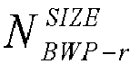
- The method of any one of claims 11 to 13, wherein a Physical Resource Block (PRB) index of a first hopping of the second common PUCCH resource is:
 a PRB index of a second hopping of the second common PUCCH resource is:
 where γPUCCH represents an index of a resource for sending the HARQ feedback information by the terminal device with RedCap, NCS represents a number of indexes in a set of initial CS indexes,

- The method of any one of claims 11 to 13, wherein a PRB index of a first hopping of the second common PUCCH resource is:
 a PRB index of a second hopping of the second common PUCCH resource is:
 where γPUCCH represents an index of a resource for sending the HARQ feedback information by the terminal device with RedCap, NCS represents a number of indexes in a set of initial CS indexes,

- The method of any one of claims 11 to 15, wherein the initial uplink BWP comprises the bandwidth for the terminal device with RedCap.
- A method for determining resources for random access, comprising:determining, by a network device, a second common Physical Uplink Control Channel (PUCCH) resource based on a frequency domain position of a first common PUCCH resource and a frequency offset,wherein the second common PUCCH resource is a resource, for sending Hybrid Automatic Repeat Request (HARQ) feedback information, within a bandwidth for a terminal device with reduced capability (RedCap), and the first common PUCCH resource is a resource, for sending HARQ feedback information, corresponding to an initial uplink bandwidth part (BWP).
- The method of claim 17, wherein the frequency offset comprises a first frequency offset and a second frequency offset.
- The method of claim 17 or 18, further comprising:
sending, by the network device, system information or a Radio Resource Control (RRC) signaling, wherein the system information or the RRC signaling carries the frequency offset. - The method of any one of claims 17 to 19, wherein the frequency offset is determined according to a predefined rule.
- The method of claim 20, wherein the predefined rule comprises that:
the frequency offset is determined based on a relationship between the initial uplink BWP and the bandwidth for the terminal device with RedCap. - The method of any one of claims 17 to 21, wherein the frequency offset comprises a first frequency offset and a second frequency offset,the first frequency offset is equal to a difference between half of a difference between the initial uplink BWP and the bandwidth for the terminal device with RedCap and a difference between a center frequency of the initial uplink BWP and a center frequency of the bandwidth for the terminal device with RedCap; andthe second frequency offset is equal to a sum of half of the difference between the initial uplink BWP and the bandwidth for the terminal device with RedCap and the difference between the center frequency of the initial uplink BWP and the center frequency of the bandwidth for the terminal device with RedCap.
- The method of any one of claims 17 to 22, wherein a first frequency domain position of the second common PUCCH resource is obtained by adding the first frequency offset to a third frequency domain position of the first common PUCCH resource that the initial uplink BWP where is located;a second frequency domain position of the second common PUCCH resource is obtained by subtracting the second frequency offset from a fourth frequency domain position of the first common PUCCH resource that is located in the initial uplink BWP, andwherein a frequency at the third frequency domain position is less than a frequency at the fourth frequency domain position.
- The method of any one of claims 17 to 23, wherein a Physical Resource Block (PRB) index of a first hopping of the second common PUCCH resource is:
 a PRB index of a second hopping of the second common PUCCH resource is:
 where γPUCCH represents an index of a resource for sending the HARQ feedback information by the terminal device with RedCap, NCS represents a number of indexes in a set of initial cyclic shift (CS) indexes,

- The method of any one of claims 17 to 23, wherein a PRB index of a first hopping of the second common PUCCH resource is:
 a PRB index of a second hopping of the second common PUCCH resource is:
 where γPUCCH represents an index of a resource for sending the HARQ feedback information by the terminal device with RedCap, NCS represents a number of indexes in a set of initial cyclic shift (CS) indexes,

- The method of any one of claims 17 to 25, wherein the initial uplink BWP comprises the bandwidth for the terminal device with RedCap.
- A method for determining resources for random access, comprising:determining, by a network device, a second common Physical Uplink Control Channel (PUCCH) resource based on configuration information of a first common PUCCH resource and a bandwidth for a terminal device with reduced capability (RedCap),wherein the second common PUCCH resource is a resource, for sending Hybrid Automatic Repeat Request (HARQ) feedback information, within the bandwidth for the terminal device with RedCap, and the first common PUCCH resource is a resource, for sending HARQ feedback information, corresponding to an initial uplink bandwidth part (BWP).
- The method of claim 27, wherein a Physical Resource Block (PRB) index of the second common PUCCH resource is determined based on a number of PRBs included in the bandwidth for the terminal device with RedCap and a PRB offset in the configuration information of the first common PUCCH resource.
- The method of claim 27 or 28, wherein a PRB index of the second common PUCCH resource is a PRB index within the bandwidth for the terminal device with RedCap, and the PRB index has a range from 0 to


- The method of any one of claims 27 to 29, wherein a Physical Resource Block (PRB) index of a first hopping of the second common PUCCH resource is:
 a PRB index of a second hopping of the second common PUCCH resource is:
 where γPUCCH represents an index of a resource for sending the HARQ feedback information by the terminal device with RedCap, NCS represents a number of indexes in a set of initial CS indexes, an index of the initial cyclic shift is PUCCH mod (NCS ) ,
- The method of any one of claims 27 to 29, wherein a PRB index of a first hopping of the second common PUCCH resource is:
 a PRB index of a second hopping of the second common PUCCH resource is:
 where γPUCCH represents an index of a resource for sending the HARQ feedback information by the terminal device with RedCap, NCS represents a number of indexes in a set of initial CS indexes, an index of the initial cyclic shift is (γPUCCH - 8)mod NCS,
- The method of any one of claims 27 to 31, wherein the initial uplink BWP comprises the bandwidth for the terminal device with RedCap.
- A terminal device, wherein the terminal device is a terminal device with reduced capability (RedCap) and comprises:a first processing unit, configured to determine a second common Physical Uplink Control Channel (PUCCH) resource based on a frequency domain position of a first common PUCCH resource and a frequency offset,wherein the second common PUCCH resource is a resource, for sending Hybrid Automatic Repeat Request (HARQ) feedback information, within a bandwidth for the terminal device with RedCap, and the first common PUCCH resource is a resource, for sending HARQ feedback information, corresponding to an initial uplink bandwidth part (BWP).
- The terminal device of claim 33, wherein the frequency offset comprises a first frequency offset and a second frequency offset.
- The terminal device of claim 33 or 34, wherein the frequency offset is configured by a network device through system information; or
the frequency offset is configured by the network device through a Radio Resource Control (RRC) signaling. - The terminal device of any one of claims 33 to 35, wherein the frequency offset is determined according to a predefined rule.
- The terminal device of claim 36, wherein the predefined rule comprises that:
the frequency offset is determined based on a relationship between the initial uplink BWP and the bandwidth for the terminal device with RedCap. - The terminal device of any one of claims 33 to 37, wherein the frequency offset comprises a first frequency offset and a second frequency offset,the first frequency offset is equal to a difference between half of a difference between the initial uplink BWP and the bandwidth for the terminal device with RedCap and a difference between a center frequency of the initial uplink BWP and a center frequency of the bandwidth for the terminal device with RedCap; andthe second frequency offset is equal to a sum of half of the difference between the initial uplink BWP and the bandwidth for the terminal device with RedCap and the difference between the center frequency of the initial uplink BWP and the center frequency of the bandwidth for the terminal device with RedCap.
- The terminal device of any one of claims 33 to 38, whereina first frequency domain position of the second common PUCCH resource is obtained by adding the first frequency offset to a third frequency domain position of the first common PUCCH resource that is located in the initial uplink BWP;a second frequency domain position of the second common PUCCH resource is obtained by subtracting the second frequency offset from a fourth frequency domain position of the first common PUCCH resource that is located in the initial uplink BWP, anda frequency at the third frequency domain position is less than a frequency at the fourth frequency domain position.
- The terminal device of any one of claims 33 to 39, wherein a Physical Resource Block (PRB) index of a first hopping of the second common PUCCH resource is:
 a PRB index of a second hopping of the second common PUCCH resource is:
 where γPUCCH represents an index of a resource for sending the HARQ feedback information by the terminal device with RedCap, NCS represents a number of indexes in a set of initial cyclic shift (CS) indexes,

- The terminal device of any one of claims 33 to 39, wherein a PRB index of a first hopping of the second common PUCCH resource is:
 a PRB index of a second hopping of the second common PUCCH resource is:
 where γPUCCH represents an index of a resource for sending the HARQ feedback information by the terminal device with RedCap, NCS represents a number of indexes in a set of initial cyclic shift (CS) indexes,

- The terminal device of any one of claims 33 to 43, wherein the initial uplink BWP comprises the bandwidth for the terminal device with RedCap.
- A terminal device, wherein the terminal device is a terminal device with reduced capability (RedCap) and comprises:a second processing unit, configured to determine a second common Physical Uplink Control Channel (PUCCH) resource based on configuration information of a first common PUCCH resource and a bandwidth for the terminal device with RedCap,wherein the second common PUCCH resource is a resource, for sending Hybrid Automatic Repeat Request (HARQ) feedback information, within the bandwidth for the terminal device with RedCap, and the first common PUCCH resource is a resource, for sending HARQ feedback information, corresponding to an initial uplink bandwidth part (BWP).
- The terminal device of claim 43, wherein a Physical Resource Block (PRB) index of the second common PUCCH resource is determined based on a number of PRBs included in the bandwidthfor the terminal device with RedCap and a PRB offset in the configuration information of the first common PUCCH resource.
- The terminal device of claim 43 or 44, wherein a PRB index of the second common PUCCH resource is a PRB index within the bandwidth for the terminal device with RedCap, and the PRB index has a range from 0 to


- The terminal device of any one of claims 43 to 45, wherein a Physical Resource Block (PRB) index of a first hopping of the second common PUCCH resource is:
 a PRB index of a second hopping of the second common PUCCH resource is:
 where γPUCCH represents an index of a resource for sending the HARQ feedback information by the terminal device with RedCap, NCS represents a number of indexes in a set of initial CS indexes,

- The terminal device of any one of claims 43 to 45, wherein a PRB index of a first hopping of the second common PUCCH resource is:
 a PRB index of a second hopping of the second common PUCCH resource is:
 where γPUCCH represents an index of a resource for sending the HARQ feedback information by the terminal device with RedCap, NCS represents a number of indexes in a set of initial CS indexes,
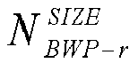
- The terminal device of any one of claims 43 to 47, wherein the initial uplink BWP comprises the bandwidth for the terminal device with RedCap.
- A network device, comprising:a third processing unit, configured to determine a second common Physical Uplink Control Channel (PUCCH) resource based on a frequency domain position of a first common PUCCH resource and a frequency offset,wherein the second common PUCCH resource is a resource, for sending Hybrid Automatic Repeat Request (HARQ) feedback information, within a bandwidth for a terminal device with reduced capability (RedCap), and the first common PUCCH resource is a resource, for sending HARQ feedback information, corresponding to an initial uplink bandwidth part (BWP).
- The network device of claim 49, wherein the frequency offset comprises a first frequency offset and a second frequency offset.
- The network device of claim 49 or 50, further comprising:
a first sending unit, configured to send system information or a Radio Resource Control (RRC) signaling, wherein the system information or the RRC signaling carries the frequency offset. - The network device of any one of claims 49 to 51, wherein the frequency offset is determined according to a predefined rule.
- The network device of claim 52, wherein the predefined rule comprises that:
the frequency offset is determined based on a relationship between the initial uplink BWP and the bandwidth for the terminal device with RedCap. - The network device of any one of claims 49 to 53, wherein the frequency offset comprises a first frequency offset and a second frequency offset,the first frequency offset is equal to a difference between half of a difference between the initial uplink BWP and the bandwidth for the terminal device with RedCap and a difference between a center frequency of the initial uplink BWP and a center frequency of the bandwidth for the terminal device with RedCap; andthe second frequency offset is equal to a sum of half of the difference between the initial uplink BWP and the bandwidth for the terminal device with RedCap and the difference between the center frequency of the initial uplink BWP and the center frequency of the bandwidth for the terminal device with RedCap.
- The network device of any one of claims 49 to 54, whereina first frequency domain position of the second common PUCCH resource is obtained by adding the first frequency offset to a third frequency domain position of the first common PUCCH resource that is located in the initial uplink BWP;a second frequency domain position of the second common PUCCH resource is obtained by subtracting the second frequency offset from a fourth frequency domain position of the first common PUCCH resource that is located in the initial uplink BWP, andwherein a frequency of at the third frequency domain position is less than a frequency of at the fourth frequency domain position.
- The network device of any one of claims 49 to 55, wherein a Physical Resource Block (PRB) index of a first hopping of the second common PUCCH resource is:
 a PRB index of a second hopping of the second common PUCCH resource is:
 where γPUCCH represents an index of a resource for sending the HARQ feedback information by the terminal device with RedCap, NCS represents a number of indexes in a set of initial cyclic shift (CS) indexes,

- The network device of any one of claims 49 to 55, wherein a PRB index of a first hopping of the second common PUCCH resource is:
 a PRB index of a second hopping of the second common PUCCH resource is:
 where γPUCCH represents an index of a resource for sending the HARQ feedback information by the terminal device with RedCap, NCS represents a number of indexes in a set of initial cyclic shift (CS) indexes,

- The network device of any one of claims 49 to 57, wherein the initial uplink BWP comprises the bandwidth for the terminal device with RedCap.
- A network device, comprising:a fourth processing unit, configured to determine a second common Physical Uplink Control Channel (PUCCH) resource based on configuration information of a first common PUCCH resource and a bandwidth correspfor a terminal device with reduced capability (RedCap),wherein the second common PUCCH resource is a resource, for sending Hybrid Automatic Repeat Request (HARQ) feedback information, within the bandwidth for the terminal device with RedCap, and the first common PUCCH resource is a resource, for sending HARQ feedback information, corresponding to an initial uplink bandwidth part (BWP).
- The network device of claim 59, wherein a Physical Resource Block (PRB) index of the second common PUCCH resource is determined based on a number of PRBs included in the bandwidth for the terminal device with RedCap and a PRB offset in the configuration information of the first common PUCCH resource.
- The network device of claim 59 or 60, wherein a PRB index of the second common PUCCH resource is a PRB index within the bandwidth for the terminal device with RedCap, and the PRB index has a range from 0 to


- The network device of any one of claims 59 to 61, wherein a Physical Resource Block (PRB) index of a first hopping of the second common PUCCH resource is:
 a PRB index of a second hopping of the second common PUCCH resource is:
 where γPUCCH represents an index of a resource for sending the HARQ feedback information by the terminal device with RedCap, NCS represents a number of indexes in a set of initial CS indexes, an index of the initial cyclic shift is PUCCH mod (NCS ) ,
- The network device of any one of claims 59 to 61, wherein a PRB index of a first hopping of the second common PUCCH resource is:
 a PRB index of a second hopping of the second common PUCCH resource is:
 where γPUCCH represents an index of a resource for sending the HARQ feedback information by the terminal device with RedCap, NCS represents a number of indexes in a set of initial CS indexes, an index of the initial cyclic shift is (γPUCCH -8)modNCS,
- The network device of any one of claims 59 to 63, wherein the initial uplink BWP comprises the bandwidth for the terminal device with RedCap.
- A terminal device, comprising a processor and a memory configured to store computer programs capable of running on the processor,
wherein the processor is configured to implement, when running the computer programs, the operations of the method for determining resources for random access according to any one of claims 1 to 10 or the operations of the method for determining resources for random access according to any one of claims 11 to 16. - A network device, comprising a processor and a memory configured to store computer programs capable of running on the processor,
wherein the processor is configured to implement, when running the computer programs, the operations of the method for determining resources for random access according to any one of claims 17 to 26, or the operations of the method for determining resources for random access according to any one of claims 27 to 32. - A storage medium having stored thereon executable programs that, when executed by a processor, cause the processor to implement the method for determining resources for random access according to any one of claims 1 to 10 or implements the method for determining resources for random access according to any one of claims 11 to 16.
- A storage medium having stored thereon executable programs that, when executed by a processor, cause the processor to implement the method for determining resources for random access according to any one of claims 17 to 26 or implements the method for determining resources for random access according to any one of claims 27 to 32.
- A computer program product comprising computer program instructions, wherein the computer program instructions cause a computer to perform the method for determining resources for random access according to any one of claims 1 to 10, or the computer program instructions causes a computer to perform the method for determining resources for random access according to any one of claims 11 to 16.
- A computer program product comprising computer program instructions, wherein the computer program instructions causes a computer to perform the method for determining resources for random access according to any one of claims 17 to 26, or the computer program instructions causing a computer to perform the method for determining resources for random access according to any one of claims 27 to 32.
- A computer program, causing a computer to perform the method for determining resources for random access according to any one of claims 1 to 10, or the computer program causing a computer to perform the method for determining resources for random access according to any one of claims 11 to 16.
- A computer program, causing a computer to perform the method for determining resources for random access according to any one of claims 17 to 26, or the computer program causing a computer to perform the method for determining resources for random access according to any one of claims 27 to 32.
- A chip, comprising: a processor configured to invoke and run computer programs from a memory, to cause a device installed with the chip to perform the method for determining resources for random access according to any one of claims 1 to 10, or perform the method for determining resources for random access according to any one of claims 11 to 16.
- A chip comprising: a processor configured to invoke and run computer programs from a memory, to cause a device installed with the chip to perform the method for determining resources for random access according to any one of claims 17 to 26, or perform the method for determining resources for random access according to any one of claims 27 to 32.
Priority Applications (1)
| Application Number | Priority Date | Filing Date | Title |
|---|---|---|---|
| EP25226225.8A EP4697637A3 (en) | 2021-03-04 | 2021-03-04 | Random access resource determining method, electronic device and storage medium |
Applications Claiming Priority (1)
| Application Number | Priority Date | Filing Date | Title |
|---|---|---|---|
| PCT/CN2021/079168 WO2022183455A1 (en) | 2021-03-04 | 2021-03-04 | Random access resource determining method, electronic device and storage medium |
Related Child Applications (2)
| Application Number | Title | Priority Date | Filing Date |
|---|---|---|---|
| EP25226225.8A Division-Into EP4697637A3 (en) | 2021-03-04 | 2021-03-04 | Random access resource determining method, electronic device and storage medium |
| EP25226225.8A Division EP4697637A3 (en) | 2021-03-04 | 2021-03-04 | Random access resource determining method, electronic device and storage medium |
Publications (3)
| Publication Number | Publication Date |
|---|---|
| EP4271084A1 true EP4271084A1 (en) | 2023-11-01 |
| EP4271084A4 EP4271084A4 (en) | 2024-02-21 |
| EP4271084B1 EP4271084B1 (en) | 2026-02-11 |
Family
ID=83154858
Family Applications (2)
| Application Number | Title | Priority Date | Filing Date |
|---|---|---|---|
| EP21928540.0A Active EP4271084B1 (en) | 2021-03-04 | 2021-03-04 | Random access resource determining method, electronic device and storage medium |
| EP25226225.8A Pending EP4697637A3 (en) | 2021-03-04 | 2021-03-04 | Random access resource determining method, electronic device and storage medium |
Family Applications After (1)
| Application Number | Title | Priority Date | Filing Date |
|---|---|---|---|
| EP25226225.8A Pending EP4697637A3 (en) | 2021-03-04 | 2021-03-04 | Random access resource determining method, electronic device and storage medium |
Country Status (6)
| Country | Link |
|---|---|
| US (1) | US12648017B2 (en) |
| EP (2) | EP4271084B1 (en) |
| CN (2) | CN116491168A (en) |
| ES (1) | ES3068884T3 (en) |
| PL (1) | PL4271084T3 (en) |
| WO (1) | WO2022183455A1 (en) |
Cited By (1)
| Publication number | Priority date | Publication date | Assignee | Title |
|---|---|---|---|---|
| US20240340870A1 (en) * | 2021-08-05 | 2024-10-10 | Panasonic Intellectual Property Corporation Of America | Terminal, base station, and communication method |
Families Citing this family (8)
| Publication number | Priority date | Publication date | Assignee | Title |
|---|---|---|---|---|
| CN115119306B (en) * | 2021-03-19 | 2025-09-05 | 维沃移动通信有限公司 | Method for determining physical uplink control channel resources, terminal, and network-side equipment |
| US20240389153A1 (en) * | 2021-04-23 | 2024-11-21 | Beijing Xiaomi Mobile Software Co., Ltd. | Method for reporting terminal capability information, and communication device |
| CN117981424A (en) * | 2021-09-29 | 2024-05-03 | 株式会社Ntt都科摩 | Terminal and communication method |
| CN115915418A (en) * | 2022-09-30 | 2023-04-04 | 中兴通讯股份有限公司 | Data sending method and receiving method, communication node and storage medium |
| WO2024206456A1 (en) * | 2023-03-27 | 2024-10-03 | Intel Corporation | Random access for reduced capability (redcap) devices |
| CN120223482A (en) * | 2023-12-26 | 2025-06-27 | 华为技术有限公司 | Communication method and communication device |
| CN117676894B (en) * | 2023-12-26 | 2024-10-29 | 天翼物联科技有限公司 | BWP resource allocation method and device, electronic equipment and storage medium |
| WO2025208382A1 (en) * | 2024-04-02 | 2025-10-09 | 北京小米移动软件有限公司 | Communication method, terminal, network device, communication system and storage medium |
Family Cites Families (11)
| Publication number | Priority date | Publication date | Assignee | Title |
|---|---|---|---|---|
| KR102060999B1 (en) * | 2011-09-30 | 2019-12-31 | 삼성전자주식회사 | Method and apparatus for transmitting and receiving control signal |
| MX378622B (en) | 2014-08-15 | 2025-03-10 | Interdigital Patent Holdings Inc | METHOD AND APPARATUS FOR SUPPORTING UPLINK TRANSMISSION AND MBMS FOR A WTRU WITH LOW BANDWIDTH. |
| US9800387B2 (en) * | 2014-11-06 | 2017-10-24 | Intel IP Corporation | Computing apparatus with cross-subframe scheduling |
| EP3400667B1 (en) * | 2016-01-08 | 2020-06-24 | Intel IP Corporation | Downlink hybrid automatic repeat request feedback for narrowband internet of things devices |
| CN108811123B (en) | 2017-05-05 | 2022-05-13 | 华为技术有限公司 | Resource allocation method, user equipment and network equipment |
| WO2019097649A1 (en) * | 2017-11-16 | 2019-05-23 | 株式会社Nttドコモ | User terminal and wireless communication method |
| GB201718999D0 (en) * | 2017-11-16 | 2018-01-03 | Ijaz Ayesha | Communication system |
| EP3537818A4 (en) * | 2018-01-12 | 2019-12-18 | LG Electronics Inc. | METHOD FOR PERFORMING UPLINK PHYSICAL CONTROL CHANNEL TRANSMISSION IN WIRELESS COMMUNICATION SYSTEM AND TERMINAL USING THE METHOD |
| WO2021231902A1 (en) * | 2020-05-14 | 2021-11-18 | Lenovo (United States) Inc. A Corporation Of Delaware | Method and apparatus for the selective decoding of physical downlink control candidates based on a determined frequency location and frequency hopping |
| CN114449655B (en) * | 2020-11-02 | 2025-05-27 | 大唐移动通信设备有限公司 | Channel transmission method, device, terminal equipment, network equipment and storage medium |
| JP7577188B2 (en) * | 2021-01-18 | 2024-11-01 | エルジー エレクトロニクス インコーポレイティド | METHOD FOR TRANSMITTING AND RECEIVING PUCCH IN A WIRELESS COMMUNICATION SYSTEM AND APPARATUS THEREFOR |
-
2021
- 2021-03-04 EP EP21928540.0A patent/EP4271084B1/en active Active
- 2021-03-04 EP EP25226225.8A patent/EP4697637A3/en active Pending
- 2021-03-04 WO PCT/CN2021/079168 patent/WO2022183455A1/en not_active Ceased
- 2021-03-04 ES ES21928540T patent/ES3068884T3/en active Active
- 2021-03-04 PL PL21928540.0T patent/PL4271084T3/en unknown
- 2021-03-04 CN CN202180074938.6A patent/CN116491168A/en active Pending
- 2021-03-04 CN CN202511118077.3A patent/CN121056109A/en active Pending
-
2023
- 2023-07-31 US US18/227,978 patent/US12648017B2/en active Active
Cited By (1)
| Publication number | Priority date | Publication date | Assignee | Title |
|---|---|---|---|---|
| US20240340870A1 (en) * | 2021-08-05 | 2024-10-10 | Panasonic Intellectual Property Corporation Of America | Terminal, base station, and communication method |
Also Published As
| Publication number | Publication date |
|---|---|
| US12648017B2 (en) | 2026-06-02 |
| CN116491168A (en) | 2023-07-25 |
| WO2022183455A1 (en) | 2022-09-09 |
| ES3068884T3 (en) | 2026-06-03 |
| EP4271084B1 (en) | 2026-02-11 |
| US20230371062A1 (en) | 2023-11-16 |
| EP4697637A2 (en) | 2026-02-18 |
| EP4271084A4 (en) | 2024-02-21 |
| CN121056109A (en) | 2025-12-02 |
| EP4697637A3 (en) | 2026-04-22 |
| PL4271084T3 (en) | 2026-05-25 |
Similar Documents
| Publication | Publication Date | Title |
|---|---|---|
| EP4271084B1 (en) | Random access resource determining method, electronic device and storage medium | |
| US11729830B2 (en) | Method for transmitting information based on channel access manners, and user equipment | |
| US20230403689A1 (en) | Method for determining random access resource, and electronic device and storage medium | |
| EP4236576B1 (en) | Random access method, communication device and storage medium | |
| US20220352923A1 (en) | Frequency hopping methods, electronic device, and storage medium | |
| US12363714B2 (en) | Method for transmitting control information, electronic device and storage medium | |
| EP4266769A1 (en) | Random access method, and electronic device and storage medium | |
| US12225585B2 (en) | Wireless communication method and terminal device | |
| US20230319896A1 (en) | Signal transmission method, terminal device and network device | |
| WO2020248143A1 (en) | Power control method, terminal device and network device | |
| US20240322985A1 (en) | Scheduling for Multiple PDSCH/PUSCH Operations | |
| US12101793B2 (en) | Uplink transmission method, electronic device, and storage medium | |
| US20230397246A1 (en) | Method for information transmission and terminal device | |
| US20230371063A1 (en) | Information transmission method, terminal device, network device, and computer storage medium | |
| EP4106466A1 (en) | Channel processing method and device, and storage medium, processor, and electronic device | |
| WO2022205434A1 (en) | Channel transmission method, electronic device, and storage medium |
Legal Events
| Date | Code | Title | Description |
|---|---|---|---|
| STAA | Information on the status of an ep patent application or granted ep patent |
Free format text: STATUS: THE INTERNATIONAL PUBLICATION HAS BEEN MADE |
|
| PUAI | Public reference made under article 153(3) epc to a published international application that has entered the european phase |
Free format text: ORIGINAL CODE: 0009012 |
|
| STAA | Information on the status of an ep patent application or granted ep patent |
Free format text: STATUS: REQUEST FOR EXAMINATION WAS MADE |
|
| 17P | Request for examination filed |
Effective date: 20230725 |
|
| AK | Designated contracting states |
Kind code of ref document: A1 Designated state(s): AL AT BE BG CH CY CZ DE DK EE ES FI FR GB GR HR HU IE IS IT LI LT LU LV MC MK MT NL NO PL PT RO RS SE SI SK SM TR |
|
| A4 | Supplementary search report drawn up and despatched |
Effective date: 20240122 |
|
| RIC1 | Information provided on ipc code assigned before grant |
Ipc: H04L 5/00 20060101ALI20240116BHEP Ipc: H04W 48/08 20090101ALI20240116BHEP Ipc: H04W 72/04 20230101AFI20240116BHEP |
|
| DAV | Request for validation of the european patent (deleted) | ||
| DAX | Request for extension of the european patent (deleted) | ||
| STAA | Information on the status of an ep patent application or granted ep patent |
Free format text: STATUS: EXAMINATION IS IN PROGRESS |
|
| 17Q | First examination report despatched |
Effective date: 20241024 |
|
| GRAP | Despatch of communication of intention to grant a patent |
Free format text: ORIGINAL CODE: EPIDOSNIGR1 |
|
| STAA | Information on the status of an ep patent application or granted ep patent |
Free format text: STATUS: GRANT OF PATENT IS INTENDED |
|
| INTG | Intention to grant announced |
Effective date: 20250327 |
|
| GRAJ | Information related to disapproval of communication of intention to grant by the applicant or resumption of examination proceedings by the epo deleted |
Free format text: ORIGINAL CODE: EPIDOSDIGR1 |
|
| STAA | Information on the status of an ep patent application or granted ep patent |
Free format text: STATUS: EXAMINATION IS IN PROGRESS |
|
| INTC | Intention to grant announced (deleted) | ||
| GRAP | Despatch of communication of intention to grant a patent |
Free format text: ORIGINAL CODE: EPIDOSNIGR1 |
|
| STAA | Information on the status of an ep patent application or granted ep patent |
Free format text: STATUS: GRANT OF PATENT IS INTENDED |
|
| INTG | Intention to grant announced |
Effective date: 20251002 |
|
| GRAS | Grant fee paid |
Free format text: ORIGINAL CODE: EPIDOSNIGR3 |
|
| GRAA | (expected) grant |
Free format text: ORIGINAL CODE: 0009210 |
|
| STAA | Information on the status of an ep patent application or granted ep patent |
Free format text: STATUS: THE PATENT HAS BEEN GRANTED |
|
| AK | Designated contracting states |
Kind code of ref document: B1 Designated state(s): AL AT BE BG CH CY CZ DE DK EE ES FI FR GB GR HR HU IE IS IT LI LT LU LV MC MK MT NL NO PL PT RO RS SE SI SK SM TR |
|
| REG | Reference to a national code |
Ref country code: CH Ref legal event code: F10 Free format text: ST27 STATUS EVENT CODE: U-0-0-F10-F00 (AS PROVIDED BY THE NATIONAL OFFICE) Effective date: 20260211 Ref country code: GB Ref legal event code: FG4D |
|
| REG | Reference to a national code |
Ref country code: DE Ref legal event code: R096 Ref document number: 602021047978 Country of ref document: DE |
|
| REG | Reference to a national code |
Ref country code: IE Ref legal event code: FG4D |
|
| REG | Reference to a national code |
Ref country code: NL Ref legal event code: FP |
|
| PGFP | Annual fee paid to national office [announced via postgrant information from national office to epo] |
Ref country code: GB Payment date: 20260325 Year of fee payment: 6 |
|
| PGFP | Annual fee paid to national office [announced via postgrant information from national office to epo] |
Ref country code: DE Payment date: 20260324 Year of fee payment: 6 |
|
| PGFP | Annual fee paid to national office [announced via postgrant information from national office to epo] |
Ref country code: NL Payment date: 20260330 Year of fee payment: 6 |
|
| PGFP | Annual fee paid to national office [announced via postgrant information from national office to epo] |
Ref country code: FR Payment date: 20260330 Year of fee payment: 6 |
|
| PGFP | Annual fee paid to national office [announced via postgrant information from national office to epo] |
Ref country code: TR Payment date: 20260331 Year of fee payment: 6 |
|
| REG | Reference to a national code |
Ref country code: ES Ref legal event code: FG2A Ref document number: 3068884 Country of ref document: ES Kind code of ref document: T3 Effective date: 20260603 |
|
| PG25 | Lapsed in a contracting state [announced via postgrant information from national office to epo] |
Ref country code: RS Free format text: LAPSE BECAUSE OF FAILURE TO SUBMIT A TRANSLATION OF THE DESCRIPTION OR TO PAY THE FEE WITHIN THE PRESCRIBED TIME-LIMIT Effective date: 20260511 |
|
| PGFP | Annual fee paid to national office [announced via postgrant information from national office to epo] |
Ref country code: ES Payment date: 20260401 Year of fee payment: 6 |
|
| PGFP | Annual fee paid to national office [announced via postgrant information from national office to epo] |
Ref country code: PL Payment date: 20260305 Year of fee payment: 6 |
|
| PG25 | Lapsed in a contracting state [announced via postgrant information from national office to epo] |
Ref country code: GR Free format text: LAPSE BECAUSE OF FAILURE TO SUBMIT A TRANSLATION OF THE DESCRIPTION OR TO PAY THE FEE WITHIN THE PRESCRIBED TIME-LIMIT Effective date: 20260512 |
|
| PGFP | Annual fee paid to national office [announced via postgrant information from national office to epo] |
Ref country code: IT Payment date: 20260408 Year of fee payment: 6 |
|
| REG | Reference to a national code |
Ref country code: LT Ref legal event code: MG9D |
|
| PG25 | Lapsed in a contracting state [announced via postgrant information from national office to epo] |
Ref country code: LT Free format text: LAPSE BECAUSE OF FAILURE TO SUBMIT A TRANSLATION OF THE DESCRIPTION OR TO PAY THE FEE WITHIN THE PRESCRIBED TIME-LIMIT Effective date: 20260211 |
|
| PG25 | Lapsed in a contracting state [announced via postgrant information from national office to epo] |
Ref country code: NO Free format text: LAPSE BECAUSE OF FAILURE TO SUBMIT A TRANSLATION OF THE DESCRIPTION OR TO PAY THE FEE WITHIN THE PRESCRIBED TIME-LIMIT Effective date: 20260511 |
|
| PG25 | Lapsed in a contracting state [announced via postgrant information from national office to epo] |
Ref country code: FI Free format text: LAPSE BECAUSE OF FAILURE TO SUBMIT A TRANSLATION OF THE DESCRIPTION OR TO PAY THE FEE WITHIN THE PRESCRIBED TIME-LIMIT Effective date: 20260211 Ref country code: SE Free format text: LAPSE BECAUSE OF FAILURE TO SUBMIT A TRANSLATION OF THE DESCRIPTION OR TO PAY THE FEE WITHIN THE PRESCRIBED TIME-LIMIT Effective date: 20260211 Ref country code: AT Free format text: LAPSE BECAUSE OF FAILURE TO SUBMIT A TRANSLATION OF THE DESCRIPTION OR TO PAY THE FEE WITHIN THE PRESCRIBED TIME-LIMIT Effective date: 20260211 |
|
| REG | Reference to a national code |
Ref country code: AT Ref legal event code: MK05 Ref document number: 1886885 Country of ref document: AT Kind code of ref document: T Effective date: 20260211 |
|
| PG25 | Lapsed in a contracting state [announced via postgrant information from national office to epo] |
Ref country code: HR Free format text: LAPSE BECAUSE OF FAILURE TO SUBMIT A TRANSLATION OF THE DESCRIPTION OR TO PAY THE FEE WITHIN THE PRESCRIBED TIME-LIMIT Effective date: 20260211 |
|
| PG25 | Lapsed in a contracting state [announced via postgrant information from national office to epo] |
Ref country code: IS Free format text: LAPSE BECAUSE OF FAILURE TO SUBMIT A TRANSLATION OF THE DESCRIPTION OR TO PAY THE FEE WITHIN THE PRESCRIBED TIME-LIMIT Effective date: 20260611 Ref country code: PT Free format text: LAPSE BECAUSE OF FAILURE TO SUBMIT A TRANSLATION OF THE DESCRIPTION OR TO PAY THE FEE WITHIN THE PRESCRIBED TIME-LIMIT Effective date: 20260611 |
|
| PG25 | Lapsed in a contracting state [announced via postgrant information from national office to epo] |
Ref country code: LV Free format text: LAPSE BECAUSE OF FAILURE TO SUBMIT A TRANSLATION OF THE DESCRIPTION OR TO PAY THE FEE WITHIN THE PRESCRIBED TIME-LIMIT Effective date: 20260211 |
|
| PG25 | Lapsed in a contracting state [announced via postgrant information from national office to epo] |
Ref country code: BG Free format text: LAPSE BECAUSE OF FAILURE TO SUBMIT A TRANSLATION OF THE DESCRIPTION OR TO PAY THE FEE WITHIN THE PRESCRIBED TIME-LIMIT Effective date: 20260211 |
|
| P01 | Opt-out of the competence of the unified patent court (upc) registered |
Free format text: CASE NUMBER: UPC_APP_0020955_4271084/2026 Effective date: 20260706 |