EP4270920A1 - Camera module, and electronic device - Google Patents
Camera module, and electronic device Download PDFInfo
- Publication number
- EP4270920A1 EP4270920A1 EP21909251.7A EP21909251A EP4270920A1 EP 4270920 A1 EP4270920 A1 EP 4270920A1 EP 21909251 A EP21909251 A EP 21909251A EP 4270920 A1 EP4270920 A1 EP 4270920A1
- Authority
- EP
- European Patent Office
- Prior art keywords
- circuit board
- lens assembly
- assembly
- drive
- camera module
- Prior art date
- Legal status (The legal status is an assumption and is not a legal conclusion. Google has not performed a legal analysis and makes no representation as to the accuracy of the status listed.)
- Granted
Links
Images


Classifications
-
- H—ELECTRICITY
- H04—ELECTRIC COMMUNICATION TECHNIQUE
- H04N—PICTORIAL COMMUNICATION, e.g. TELEVISION
- H04N23/00—Cameras or camera modules comprising electronic image sensors; Control thereof
- H04N23/50—Constructional details
- H04N23/54—Mounting of pick-up tubes, electronic image sensors, deviation or focusing coils
-
- G—PHYSICS
- G03—PHOTOGRAPHY; CINEMATOGRAPHY; ANALOGOUS TECHNIQUES USING WAVES OTHER THAN OPTICAL WAVES; ELECTROGRAPHY; HOLOGRAPHY
- G03B—APPARATUS OR ARRANGEMENTS FOR TAKING PHOTOGRAPHS OR FOR PROJECTING OR VIEWING THEM; APPARATUS OR ARRANGEMENTS EMPLOYING ANALOGOUS TECHNIQUES USING WAVES OTHER THAN OPTICAL WAVES; ACCESSORIES THEREFOR
- G03B5/00—Adjustment of optical system relative to image or object surface other than for focusing
-
- H—ELECTRICITY
- H04—ELECTRIC COMMUNICATION TECHNIQUE
- H04N—PICTORIAL COMMUNICATION, e.g. TELEVISION
- H04N23/00—Cameras or camera modules comprising electronic image sensors; Control thereof
- H04N23/50—Constructional details
- H04N23/51—Housings
-
- G—PHYSICS
- G03—PHOTOGRAPHY; CINEMATOGRAPHY; ANALOGOUS TECHNIQUES USING WAVES OTHER THAN OPTICAL WAVES; ELECTROGRAPHY; HOLOGRAPHY
- G03B—APPARATUS OR ARRANGEMENTS FOR TAKING PHOTOGRAPHS OR FOR PROJECTING OR VIEWING THEM; APPARATUS OR ARRANGEMENTS EMPLOYING ANALOGOUS TECHNIQUES USING WAVES OTHER THAN OPTICAL WAVES; ACCESSORIES THEREFOR
- G03B17/00—Details of cameras or camera bodies; Accessories therefor
- G03B17/02—Bodies
- G03B17/12—Bodies with means for supporting objectives, supplementary lenses, filters, masks, or turrets
-
- G—PHYSICS
- G03—PHOTOGRAPHY; CINEMATOGRAPHY; ANALOGOUS TECHNIQUES USING WAVES OTHER THAN OPTICAL WAVES; ELECTROGRAPHY; HOLOGRAPHY
- G03B—APPARATUS OR ARRANGEMENTS FOR TAKING PHOTOGRAPHS OR FOR PROJECTING OR VIEWING THEM; APPARATUS OR ARRANGEMENTS EMPLOYING ANALOGOUS TECHNIQUES USING WAVES OTHER THAN OPTICAL WAVES; ACCESSORIES THEREFOR
- G03B30/00—Camera modules comprising integrated lens units and imaging units, specially adapted for being embedded in other devices, e.g. mobile phones or vehicles
-
- H—ELECTRICITY
- H04—ELECTRIC COMMUNICATION TECHNIQUE
- H04N—PICTORIAL COMMUNICATION, e.g. TELEVISION
- H04N23/00—Cameras or camera modules comprising electronic image sensors; Control thereof
- H04N23/50—Constructional details
- H04N23/55—Optical parts specially adapted for electronic image sensors; Mounting thereof
-
- H—ELECTRICITY
- H04—ELECTRIC COMMUNICATION TECHNIQUE
- H04N—PICTORIAL COMMUNICATION, e.g. TELEVISION
- H04N23/00—Cameras or camera modules comprising electronic image sensors; Control thereof
- H04N23/57—Mechanical or electrical details of cameras or camera modules specially adapted for being embedded in other devices
-
- H—ELECTRICITY
- H04—ELECTRIC COMMUNICATION TECHNIQUE
- H04N—PICTORIAL COMMUNICATION, e.g. TELEVISION
- H04N23/00—Cameras or camera modules comprising electronic image sensors; Control thereof
- H04N23/60—Control of cameras or camera modules
- H04N23/68—Control of cameras or camera modules for stable pick-up of the scene, e.g. compensating for camera body vibrations
- H04N23/682—Vibration or motion blur correction
- H04N23/685—Vibration or motion blur correction performed by mechanical compensation
-
- H—ELECTRICITY
- H04—ELECTRIC COMMUNICATION TECHNIQUE
- H04N—PICTORIAL COMMUNICATION, e.g. TELEVISION
- H04N23/00—Cameras or camera modules comprising electronic image sensors; Control thereof
- H04N23/60—Control of cameras or camera modules
- H04N23/695—Control of camera direction for changing a field of view, e.g. pan, tilt or based on tracking of objects
-
- H—ELECTRICITY
- H05—ELECTRIC TECHNIQUES NOT OTHERWISE PROVIDED FOR
- H05K—PRINTED CIRCUITS; CASINGS OR CONSTRUCTIONAL DETAILS OF ELECTRIC APPARATUS; MANUFACTURE OF ASSEMBLAGES OF ELECTRICAL COMPONENTS
- H05K1/00—Printed circuits
- H05K1/02—Details
- H05K1/14—Structural association of two or more printed circuits
- H05K1/147—Structural association of two or more printed circuits at least one of the printed circuits being bent or folded, e.g. by using a flexible printed circuit
-
- G—PHYSICS
- G03—PHOTOGRAPHY; CINEMATOGRAPHY; ANALOGOUS TECHNIQUES USING WAVES OTHER THAN OPTICAL WAVES; ELECTROGRAPHY; HOLOGRAPHY
- G03B—APPARATUS OR ARRANGEMENTS FOR TAKING PHOTOGRAPHS OR FOR PROJECTING OR VIEWING THEM; APPARATUS OR ARRANGEMENTS EMPLOYING ANALOGOUS TECHNIQUES USING WAVES OTHER THAN OPTICAL WAVES; ACCESSORIES THEREFOR
- G03B2205/00—Adjustment of optical system relative to image or object surface other than for focusing
- G03B2205/0007—Movement of one or more optical elements for control of motion blur
-
- G—PHYSICS
- G03—PHOTOGRAPHY; CINEMATOGRAPHY; ANALOGOUS TECHNIQUES USING WAVES OTHER THAN OPTICAL WAVES; ELECTROGRAPHY; HOLOGRAPHY
- G03B—APPARATUS OR ARRANGEMENTS FOR TAKING PHOTOGRAPHS OR FOR PROJECTING OR VIEWING THEM; APPARATUS OR ARRANGEMENTS EMPLOYING ANALOGOUS TECHNIQUES USING WAVES OTHER THAN OPTICAL WAVES; ACCESSORIES THEREFOR
- G03B2205/00—Adjustment of optical system relative to image or object surface other than for focusing
- G03B2205/0053—Driving means for the movement of one or more optical element
- G03B2205/0069—Driving means for the movement of one or more optical element using electromagnetic actuators, e.g. voice coils
Definitions
- This application pertains to the field of camera technologies, and specifically, relates to a camera module and an electronic device.
- This application is intended to provide a camera module and an electronic device to resolve at least one of the problems that have been found by the inventors.
- an embodiment of this application provides a camera module.
- the camera module includes: a housing, an accommodating chamber being provided in the housing; a lens assembly, the lens assembly being movably disposed in the accommodating chamber; a first drive assembly, the first drive assembly being connected to the lens assembly so as to drive the lens assembly to move, and at least part of the first drive assembly being disposed on an inner side wall of the housing; a circuit board, the circuit board being connected to the lens assembly; and a second drive assembly, the second drive assembly being disposed in the housing, and at least part of the second drive assembly being connected to the circuit board so as to drive the circuit board to move.
- an embodiment of this application provides an electronic device including the foregoing camera module.
- the first drive assembly and the second drive assembly are used to drive the lens assembly and the circuit board respectively so that the circuit board and the lens assembly move in a same direction, preventing the lens assembly from pulling the circuit board when in motion, thereby enabling the lens assembly to move a longer distance and rotate a larger angle.
- the terms “mount”, “connect”, and “attach” should be understood in their general senses. For example, they may refer to a fixed connection, a detachable connection, or an integral connection; a mechanical connection or an electrical connection; and a direct connection, an indirect connection via an intermediate medium, or an internal communication between two elements. Persons of ordinary skill in the art can understand specific meanings of these terms in this application as appropriate to specific situations.
- FIG. 1 shows an anti-shake gimbal in the prior art.
- a flexible circuit board 1 in an existing anti-shake gimbal enters a sealed flexible circuit board box 3 after its wire is led out of a side of a camera module head 2.
- the flexible circuit board box 3 the flexible circuit board is folded into five layers in an S shape and then extends out of the flexible circuit board box 3 to be connected to a main board.
- this scheme still cannot effectively prevent the flexible circuit board 1 from pulling the gimbal, limiting the optical anti-shake performance.
- a camera module 100 includes a housing 10, a lens assembly 20, a first drive assembly 30, a circuit board 40, and a second drive assembly 50.
- an accommodating chamber 11 is provided in the housing 10.
- the lens assembly 20 is movably disposed in the accommodating chamber 11.
- the first drive assembly 30 is connected to the lens assembly 20 so as to drive the lens assembly 20 to move. At least part of the first drive assembly 30 is disposed in the housing 10.
- the circuit board 40 is connected to the lens assembly 20.
- the second drive assembly 50 is disposed in the housing 10, and at least part of the second drive assembly 50 is connected to the circuit board 40 so as to drive the circuit board 40 to move.
- the camera module 100 mainly includes a housing 10, a lens assembly 20 mounted in the housing 10, a first drive assembly 30 driving the lens assembly 20 to move, a circuit board 40 electrically connected to the lens assembly 20, and a second drive assembly 50 driving the circuit board 40 to move.
- the housing 10 is a basic component of the camera module 100, and the housing 10 can provide a foundation for installing other components of the camera module 100.
- the housing 10 has an accommodating chamber 11, and the accommodating chamber 11 can be used to accommodate the lens assembly 20.
- the camera module 100 may tilt due to shaking, eventually affecting the quality of the shot.
- the lens assembly 20 is movable with respect to the housing 10, and the first drive assembly 30 drives the lens assembly 20 to move so as to compensate tilt caused by shake of the camera module 100, thereby effectively stabilizing the camera module 100.
- the second drive assembly 50 is capable of driving the circuit board 40 to move in the same direction, alleviating the pulling caused by the lens assembly 20 to the circuit board 40. It should be noted that movement of the lens assembly 20 includes translation and rotation, which is not limited herein.
- the first drive assembly 30 may be connected to the lens assembly 20 in a prior manner.
- a part of the first drive assembly 30 is connected to the housing 10, and another part of the first drive assembly 30 is connected to the lens assembly 20.
- the second drive assembly 50 may be partially mounted in the accommodating chamber 11 and connected to the circuit board 40, or entirely mounted outside the accommodating chamber 11 and connected to the circuit board 40.
- first drive assembly 30 and the second drive assembly 50 include but are not limited to motors, but may instead be other drive structures that can make the lens assembly 20 and the circuit board 40 move, for example, driving motors or driving motors plus cooperating transmission means.
- the first drive assembly 30 and the second drive assembly 50 are used to drive the lens assembly 20 and the circuit board 40 respectively so that the circuit board 40 and the lens assembly 20 move in a same direction, preventing the lens assembly 20 from pulling the circuit board 40 when in motion, thereby enabling the lens assembly 20 to move a longer distance and rotate a larger angle.
- the circuit board 40 and the lens assembly 20 are driven to move synchronously by the second drive assembly 50 and the first drive assembly 30 respectively, further avoiding relative motion between the circuit board 40 and the lens assembly 20, thereby further improving the anti-pulling effect of the circuit board 40.
- the first drive assembly 30 includes a first magnetic part 31 and a first coil 32, where one of the first magnetic part 31 and the first coil 32 is connected to the housing 10, the other of the first magnetic part 31 and the first coil 32 is connected to the lens assembly 20, and when energized, the first coil 32 is movable with respect to the first magnetic part 31 so as to drive the lens assembly 20.
- the first magnetic part 31 may be disposed on the housing 10 and the first coil 32 may be disposed on the lens assembly 20; or the first magnetic part 31 may be disposed on the lens assembly 20 and the first coil 32 may be disposed on the housing 10.
- the first magnetic part 31 is disposed on an outer wall surface of the lens assembly 20, and the first coil 32 is disposed on an inner wall surface of the housing 10 and corresponds to the first magnetic part 31 in position.
- the housing 10 includes a bracket 12 and a cover plate 13, where the bracket 12 is provided with the accommodating chamber 11 having an opening on a first side, the lens assembly 20 can be disposed in the accommodating chamber 11 and is movable with respect to the bracket 12, and the circuit board 40 can be connected to the lens assembly 20 via the opening.
- the cover plate 13 is disposed on the first side of the bracket 12, and the second drive assembly 50 is disposed at the cover plate 13.
- a part of the second drive assembly 50 may be disposed at the cover plate 13, and another part of the second drive assembly 50 may be disposed at the circuit board 40 and movable with respect to the cover plate 13.
- the circuit board 40 includes a first board body 41 and a second board body 42.
- the first board body 41 is disposed between the lens assembly 20 and the cover plate 13. A first side of the first board body 41 is connected to the lens assembly 20 and moves synchronously with the lens assembly 20.
- the second board body 42 is electrically connected to the first board body 41.
- the second drive assembly 50 is disposed between the second board body 42 and the cover plate 13, and the second drive assembly 50 is connected to the second board body 42 so as to drive the second board body 42 to move.
- the second board body 42 may be a flexible circuit board, a wire conductor, or the like.
- the camera module 100 is assembled along a vertical direction, with its front close to an observer and its back facing away from the observer.
- the accommodating chamber 11 is defined inside the bracket 12, with an opening provided on the lower side of the bracket 12.
- the circuit board 40 is provided at the front side of the bracket 12, and the cover plate 13 is provided below the bracket 12 and the circuit board 40.
- the first board body 41 is on the rear side of the second board body 42 and below the lens assembly 20. During assembly, the first board body 41 extends between the bracket 12 and the cover plate 13 so as to be electrically connected to the lens assembly 20.
- a lower end face of the second board body 42 is connected to the second drive assembly 50 so that the second board body 42 and the lens assembly 20 move in a same direction.
- the circuit board 40 being divided to the first board body 41 and the second board body 42 facilitates connection of the circuit board 40 and the lens assembly 20 as well as movement of the lens assembly 20 while ensuring connection of the circuit board 40 and the second drive assembly 50.
- the first board body 41 is a circuit board
- the second board body 42 is a flexible circuit board.
- the second board body 42 can be folded in an S shape.
- the second board body 42 can stretch or retract synchronously, thus expanding a movement range of the lens assembly 20.
- the second board body 42 and the second drive assembly 50 are disposed opposite each other, thereby making full use of the space below the second board body 42.
- the housing 10 further includes a flexible circuit board storage part 60, as shown in FIG. 3 , the flexible circuit board storage part 60 may be located on the front side of the bracket 12, and the second board body 42 and the second drive assembly 50 may both be located in the flexible circuit board storage part 60, thus making full use of the storage space for the flexible circuit board.
- the second drive assembly 50 includes a second magnetic part 51 and a second coil 52, where one of the second magnetic part 51 and the second coil 52 is connected to the cover plate 13, the other of the second magnetic part 51 and the second coil 52 is connected to the second board body 42, and when energized, the second coil 52 is movable with respect to the second magnetic part 51 so as to drive the second board body 42.
- the second magnetic part 51 may be disposed on the cover plate 13 and the second coil 52 may be disposed on the second board body 42; or the second magnetic part 51 may be disposed on the second board body 42 and the second coil 52 may be disposed on the cover plate 13.
- the second magnetic part 51 is disposed on a lower end face of the second board body 42
- the second coil 52 is disposed on an upper end face of the cover plate 13.
- the second magnetic part 51 cooperates with the second coil 52.
- the second magnetic part 51 can provide a magnetic field.
- the second coil 52 When energized, the second coil 52 generates a force perpendicular to the magnetic field according to Fleming's left-hand rule, and that force can control movement of the circuit board 40 when acting on the circuit board 40.
- the first magnetic part 31 cooperates with the first coil 32, where the first coil 32 can provide a thrust when energized.
- the lens assembly 20 can be mounted on the bracket 12 through crossed support shafts 14 that are diagonally interconnected.
- the crossed support shaft 14 may include two hinged shafts perpendicular to each other.
- the first drive assembly 30 may include two first magnetic parts 31 and two first coils 32, and the first drive assembly 30 drives the lens assembly 20 to rotate about one of the two hinged shafts. It should be noted that, in embodiments of this application, how technologically the first drive assembly 30 drives the lens assembly 20 to rotate is commonly known technology, about which details are not described herein.
- the second coil 52 of the second drive assembly 50 includes one or more coils.
- the following describes various types of the second drive assembly 50.
- One coil is provided. That one coil enables the circuit board 40 to do various types of movements.
- the coil in a case that the coil is a linear conductor, it moves when energized.
- the linear conductor moves reversely, so as to drive the circuit board 40 to move.
- the coil is an annular conductor
- the annular conductor when it is energized, two sides thereof are subjected to action forces in different directions, so the annular conductor can rotate around its axis, thereby driving the circuit board 40 to rotate in a specific direction.
- the second coil 52 includes two annular coils, and the two annular coils are spaced apart on the second board body 42.
- the two annular coils may be a first annular coil and a second annular coil, respectively, where the first annular coil and the second annular coil may share one magnet.
- One of the first annular coil and the second annular coil is separately controlled to operate, so that the second board body 42 can rotate in a specific direction.
- the lower end face of the second board body 42 is approximately a rectangular part.
- a straight line parallel to a length direction of the second board body 42 is referred to as an axis Y
- a straight line parallel to a width direction of the second board body 42 is referred to as an axis X
- a straight line perpendicular to a plane on which the second board body 42 is located is referred to as an axis Z.
- the second board body 42 may be folded approximately along the axis Z.
- the first annular coil and the second annular coil are located on the lower end face of the second board body 42 and are spaced apart along the length direction of the second board body 42.
- the first annular coil and the second annular coil are both elliptic parts extending approximately along the width direction of the second board body 42.
- the second magnetic part 51 is a plate structure. This means the second magnetic part 51 may be a flat coil to effectively save space.
- the second magnetic part 51 is attached to the cover plate 13 for easy assembly. It should be noted that the second magnetic part 51 may be mounted on the cover plate 13 in other mounting manners, for example, detachable mounting manners such as clamping and insertion.
- the camera module 100 further includes a flexible circuit board position feedback element 70, where the flexible circuit board position feedback element 70 can be used to report a real-time position of the circuit board 30.
- the flexible circuit board position feedback element 70 may be a Hall chip or the like, which is not limited herein.
- the camera module further includes a lens assembly position feedback element, where the lens assembly position feedback element can be connected to the first drive assembly 30.
- the lens assembly position feedback element can be connected to the first drive assembly 30.
- the flexible circuit board is provided with an additional closed-loop control system such that the flexible circuit board can move with the lens assembly, thereby avoiding interference caused by the flexible circuit board to the lens assembly, improving the anti-shake performance of the lens assembly.
- An embodiment of this application further provides an electronic device including the camera module 100 according to any one of the foregoing embodiments.
- the lens assembly 20 can be electrically connected to a main board of the electronic device through the circuit board 40, so as to be supplied with power.
- the electronic device in this embodiment of this application may be a smart phone, a tablet computer, a wearable device, or the like, which is not limited herein.
Landscapes
- Engineering & Computer Science (AREA)
- Multimedia (AREA)
- Signal Processing (AREA)
- Physics & Mathematics (AREA)
- General Physics & Mathematics (AREA)
- Microelectronics & Electronic Packaging (AREA)
- Adjustment Of Camera Lenses (AREA)
- Studio Devices (AREA)
- Camera Bodies And Camera Details Or Accessories (AREA)
- Lens Barrels (AREA)
Abstract
Description
- This application claims priority to
Chinese Patent Application No. 202011541995.4 filed on December 23, 2020 - This application pertains to the field of camera technologies, and specifically, relates to a camera module and an electronic device.
- With the rapid development of information network technologies, video has become the first choice for daily communication and sharing of people. Therefore, increasingly high requirements are imposed on image quality in a video shooting process. However, the anti-shake capability of conventional optical anti-shake cameras no longer meets the needs of people, affecting user experience. In order to improve the anti-shake performance of cameras, a gimbal system is built into cameras, especially mobile phone cameras. Gimbal cameras differ from conventional optical anti-shake cameras in actuation. The actuation of an optical anti-shake camera means motion inside the module while a gimbal camera entails motion of the entire module.
- In the implementation process of this application, the inventors have found at least the following problem in the prior art: when a gimbal is in motion, a flexible circuit board would pull the gimbal to interfere with the motion of the gimbal.
- This application is intended to provide a camera module and an electronic device to resolve at least one of the problems that have been found by the inventors.
- According to a first aspect, an embodiment of this application provides a camera module. The camera module includes: a housing, an accommodating chamber being provided in the housing; a lens assembly, the lens assembly being movably disposed in the accommodating chamber; a first drive assembly, the first drive assembly being connected to the lens assembly so as to drive the lens assembly to move, and at least part of the first drive assembly being disposed on an inner side wall of the housing; a circuit board, the circuit board being connected to the lens assembly; and a second drive assembly, the second drive assembly being disposed in the housing, and at least part of the second drive assembly being connected to the circuit board so as to drive the circuit board to move.
- According to a second aspect, an embodiment of this application provides an electronic device including the foregoing camera module.
- In the embodiments of this application, the first drive assembly and the second drive assembly are used to drive the lens assembly and the circuit board respectively so that the circuit board and the lens assembly move in a same direction, preventing the lens assembly from pulling the circuit board when in motion, thereby enabling the lens assembly to move a longer distance and rotate a larger angle.
- Additional aspects and advantages of the embodiments of this application will be given in part in the following description, part of which will become apparent from the following description or be learned from the practice of the embodiments of this application.
- The above and/or additional aspects and advantages of this application will become obvious and easy to understand from the description of the embodiments with reference to the following drawings.
-
FIG. 1 is a cross-sectional view of an anti-shake gimbal in a related art; -
FIG. 2 is a top view of a camera module according to an embodiment of this application; -
FIG. 3 is a partial exploded view of a camera module according to an embodiment of this application; -
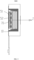
FIG. 4 is a cross-sectional view along line A-A inFIG. 2 ; -
FIG. 5 is a cross-sectional view along line B-B inFIG. 2 ; and -
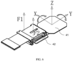
FIG. 6 is a schematic diagram showing forces experienced by a circuit board of a camera module according to an embodiment of this application. -
-
camera module 100; -
housing 10;accommodating chamber 11;bracket 12;cover plate 13; crossed support shaft 14; -
lens assembly 20; -
first drive assembly 30; firstmagnetic part 31;first coil 32; -
circuit board 40;first board body 41;second board body 42; -
second drive assembly 50; secondmagnetic part 51;second coil 52; - flexible circuit
board storage part 60; - flexible circuit board
position feedback element 70; lens assemblyposition feedback element 80; -
flexible circuit board 1;camera module head 2; and flexiblecircuit board box 3. - The embodiments of this application are described in detail below. Examples of the embodiments are shown in the accompanying drawings, and reference signs that are the same or similar always indicate the same or similar components or components with the same or similar functions. The embodiments described below with reference to the drawings are illustrative and merely for explaining this application. They should not be construed as limitations on this application. Persons of ordinary skill in the art can still obtain other embodiments based on the embodiments of this application without creative efforts, and all these embodiments shall fall within the protection scope of this application.
- A feature modified by the term "first", "second", or the like in the specification and claims of this application can explicitly or implicitly include one or more such features. In the descriptions of this application, "a plurality of" means two or more unless otherwise stated. In addition, "and/or" in the specification and claims represents at least one of connected objects, and the character "/" generally indicates that the contextually associated objects have an "or" relationship.
- In the description of this application, it should be understood that the orientations or positional relationships indicated by the technical terms "center", "longitudinal", "transverse", "length", "width", "thickness", "upper", "lower", "front", "rear", "left", "right", "vertical", "horizontal", "top", "bottom", "inside", "outside", "clockwise", "counterclockwise", "axial", " radial", "circumferential", and the like are based on the orientations or positional relationships as shown in the accompanying drawings. These terms are merely for the ease and brevity of description of this application rather than indicating or implying that the apparatuses or components mentioned must have specific orientations or must be constructed or manipulated according to specific orientations, and therefore shall not be construed as any limitations on this application.
- In the description of this application, it should be noted that unless otherwise specified and defined explicitly, the terms "mount", "connect", and "attach" should be understood in their general senses. For example, they may refer to a fixed connection, a detachable connection, or an integral connection; a mechanical connection or an electrical connection; and a direct connection, an indirect connection via an intermediate medium, or an internal communication between two elements. Persons of ordinary skill in the art can understand specific meanings of these terms in this application as appropriate to specific situations.
-
FIG. 1 shows an anti-shake gimbal in the prior art. - As shown in
FIG. 1 , aflexible circuit board 1 in an existing anti-shake gimbal enters a sealed flexiblecircuit board box 3 after its wire is led out of a side of acamera module head 2. In the flexiblecircuit board box 3, the flexible circuit board is folded into five layers in an S shape and then extends out of the flexiblecircuit board box 3 to be connected to a main board. In this way, during actuation of the camera module, there is still space for theflexible circuit board 1 to stretch or retract in the flexiblecircuit board box 3, and thus resistance is reduced. However, this scheme still cannot effectively prevent theflexible circuit board 1 from pulling the gimbal, limiting the optical anti-shake performance. - In view of this, the inventors of this application have creatively obtained the following invention by long-term research and experiments.
- A
camera module 100 according to an embodiment of this application includes ahousing 10, alens assembly 20, afirst drive assembly 30, acircuit board 40, and asecond drive assembly 50. - Specifically, an
accommodating chamber 11 is provided in thehousing 10. Thelens assembly 20 is movably disposed in theaccommodating chamber 11. Thefirst drive assembly 30 is connected to thelens assembly 20 so as to drive thelens assembly 20 to move. At least part of thefirst drive assembly 30 is disposed in thehousing 10. Thecircuit board 40 is connected to thelens assembly 20. Thesecond drive assembly 50 is disposed in thehousing 10, and at least part of thesecond drive assembly 50 is connected to thecircuit board 40 so as to drive thecircuit board 40 to move. - In other words, the
camera module 100 according to this embodiment of this application mainly includes ahousing 10, alens assembly 20 mounted in thehousing 10, afirst drive assembly 30 driving thelens assembly 20 to move, acircuit board 40 electrically connected to thelens assembly 20, and asecond drive assembly 50 driving thecircuit board 40 to move. Thehousing 10 is a basic component of thecamera module 100, and thehousing 10 can provide a foundation for installing other components of thecamera module 100. In an embodiment of this application, thehousing 10 has anaccommodating chamber 11, and theaccommodating chamber 11 can be used to accommodate thelens assembly 20. - In a specific shooting process, the
camera module 100 may tilt due to shaking, eventually affecting the quality of the shot. In thecamera module 100 disclosed in embodiments of this application, thelens assembly 20 is movable with respect to thehousing 10, and thefirst drive assembly 30 drives thelens assembly 20 to move so as to compensate tilt caused by shake of thecamera module 100, thereby effectively stabilizing thecamera module 100. - In an embodiment of this application, while the
first drive assembly 30 is driving thelens assembly 20 to move, thesecond drive assembly 50 is capable of driving thecircuit board 40 to move in the same direction, alleviating the pulling caused by thelens assembly 20 to thecircuit board 40. It should be noted that movement of thelens assembly 20 includes translation and rotation, which is not limited herein. - It should be noted that when to be mounted, the
first drive assembly 30 may be connected to thelens assembly 20 in a prior manner. For example, as shown inFIG. 2 to FIG. 5 , a part of thefirst drive assembly 30 is connected to thehousing 10, and another part of thefirst drive assembly 30 is connected to thelens assembly 20. - When to be mounted, the
second drive assembly 50 may be partially mounted in theaccommodating chamber 11 and connected to thecircuit board 40, or entirely mounted outside theaccommodating chamber 11 and connected to thecircuit board 40. - In addition, the
first drive assembly 30 and thesecond drive assembly 50 include but are not limited to motors, but may instead be other drive structures that can make thelens assembly 20 and thecircuit board 40 move, for example, driving motors or driving motors plus cooperating transmission means. - As such, according to the
camera module 100 in this embodiment of this application, thefirst drive assembly 30 and thesecond drive assembly 50 are used to drive thelens assembly 20 and thecircuit board 40 respectively so that thecircuit board 40 and thelens assembly 20 move in a same direction, preventing thelens assembly 20 from pulling thecircuit board 40 when in motion, thereby enabling thelens assembly 20 to move a longer distance and rotate a larger angle. - According to this embodiment of this application, the
circuit board 40 and thelens assembly 20 are driven to move synchronously by thesecond drive assembly 50 and thefirst drive assembly 30 respectively, further avoiding relative motion between thecircuit board 40 and thelens assembly 20, thereby further improving the anti-pulling effect of thecircuit board 40. - In some specific implementations of this application, the
first drive assembly 30 includes a firstmagnetic part 31 and afirst coil 32, where one of the firstmagnetic part 31 and thefirst coil 32 is connected to thehousing 10, the other of the firstmagnetic part 31 and thefirst coil 32 is connected to thelens assembly 20, and when energized, thefirst coil 32 is movable with respect to the firstmagnetic part 31 so as to drive thelens assembly 20. In other words, the firstmagnetic part 31 may be disposed on thehousing 10 and thefirst coil 32 may be disposed on thelens assembly 20; or the firstmagnetic part 31 may be disposed on thelens assembly 20 and thefirst coil 32 may be disposed on thehousing 10. For example, as shown inFIG. 4 andFIG. 5 , the firstmagnetic part 31 is disposed on an outer wall surface of thelens assembly 20, and thefirst coil 32 is disposed on an inner wall surface of thehousing 10 and corresponds to the firstmagnetic part 31 in position. - According to an embodiment of this application, the
housing 10 includes abracket 12 and acover plate 13, where thebracket 12 is provided with theaccommodating chamber 11 having an opening on a first side, thelens assembly 20 can be disposed in theaccommodating chamber 11 and is movable with respect to thebracket 12, and thecircuit board 40 can be connected to thelens assembly 20 via the opening. Thecover plate 13 is disposed on the first side of thebracket 12, and thesecond drive assembly 50 is disposed at thecover plate 13. Optionally, a part of thesecond drive assembly 50 may be disposed at thecover plate 13, and another part of thesecond drive assembly 50 may be disposed at thecircuit board 40 and movable with respect to thecover plate 13. - Further, the
circuit board 40 includes afirst board body 41 and asecond board body 42. Thefirst board body 41 is disposed between thelens assembly 20 and thecover plate 13. A first side of thefirst board body 41 is connected to thelens assembly 20 and moves synchronously with thelens assembly 20. Thesecond board body 42 is electrically connected to thefirst board body 41. Thesecond drive assembly 50 is disposed between thesecond board body 42 and thecover plate 13, and thesecond drive assembly 50 is connected to thesecond board body 42 so as to drive thesecond board body 42 to move. Thesecond board body 42 may be a flexible circuit board, a wire conductor, or the like. - For ease of description, the following defines that the
camera module 100 is assembled along a vertical direction, with its front close to an observer and its back facing away from the observer. - As shown in
FIG. 3 , theaccommodating chamber 11 is defined inside thebracket 12, with an opening provided on the lower side of thebracket 12. Thecircuit board 40 is provided at the front side of thebracket 12, and thecover plate 13 is provided below thebracket 12 and thecircuit board 40. Thefirst board body 41 is on the rear side of thesecond board body 42 and below thelens assembly 20. During assembly, thefirst board body 41 extends between thebracket 12 and thecover plate 13 so as to be electrically connected to thelens assembly 20. In addition, a lower end face of thesecond board body 42 is connected to thesecond drive assembly 50 so that thesecond board body 42 and thelens assembly 20 move in a same direction. Thecircuit board 40 being divided to thefirst board body 41 and thesecond board body 42 facilitates connection of thecircuit board 40 and thelens assembly 20 as well as movement of thelens assembly 20 while ensuring connection of thecircuit board 40 and thesecond drive assembly 50. - It should be noted that the upper side, lower side, front side, and rear side as described above are defined for ease of description of the positional relationships or connection relationships of the components of the
camera module 100 in the embodiments of this application, which do not limit the embodiments of this application in any sense. - In addition, for like parts or components in the embodiments of this application, there may be only one of the parts or components labeled by a reference sign, and that reference sign is equally applicable to other like parts or components.
- Optionally, the
first board body 41 is a circuit board, and thesecond board body 42 is a flexible circuit board. During assembly, thesecond board body 42 can be folded in an S shape. When thelens assembly 20 is moving, thesecond board body 42 can stretch or retract synchronously, thus expanding a movement range of thelens assembly 20. Further, thesecond board body 42 and thesecond drive assembly 50 are disposed opposite each other, thereby making full use of the space below thesecond board body 42. In a case that thehousing 10 further includes a flexible circuitboard storage part 60, as shown inFIG. 3 , the flexible circuitboard storage part 60 may be located on the front side of thebracket 12, and thesecond board body 42 and thesecond drive assembly 50 may both be located in the flexible circuitboard storage part 60, thus making full use of the storage space for the flexible circuit board. - According to an embodiment of this application, the
second drive assembly 50 includes a secondmagnetic part 51 and asecond coil 52, where one of the secondmagnetic part 51 and thesecond coil 52 is connected to thecover plate 13, the other of the secondmagnetic part 51 and thesecond coil 52 is connected to thesecond board body 42, and when energized, thesecond coil 52 is movable with respect to the secondmagnetic part 51 so as to drive thesecond board body 42. In other words, the secondmagnetic part 51 may be disposed on thecover plate 13 and thesecond coil 52 may be disposed on thesecond board body 42; or the secondmagnetic part 51 may be disposed on thesecond board body 42 and thesecond coil 52 may be disposed on thecover plate 13. For example, as shown inFIG. 3 , the secondmagnetic part 51 is disposed on a lower end face of thesecond board body 42, and thesecond coil 52 is disposed on an upper end face of thecover plate 13. - The following describes operating principles of the
first drive assembly 30 and thesecond drive assembly 50 in the embodiments of this application with reference to the accompanying drawings. - The second
magnetic part 51 cooperates with thesecond coil 52. The secondmagnetic part 51 can provide a magnetic field. When energized, thesecond coil 52 generates a force perpendicular to the magnetic field according to Fleming's left-hand rule, and that force can control movement of thecircuit board 40 when acting on thecircuit board 40. Similarly, the firstmagnetic part 31 cooperates with thefirst coil 32, where thefirst coil 32 can provide a thrust when energized. - In an embodiment of this application, as shown in
FIG. 3 , thelens assembly 20 can be mounted on thebracket 12 through crossed support shafts 14 that are diagonally interconnected. The crossed support shaft 14 may include two hinged shafts perpendicular to each other. Thefirst drive assembly 30 may include two firstmagnetic parts 31 and twofirst coils 32, and thefirst drive assembly 30 drives thelens assembly 20 to rotate about one of the two hinged shafts. It should be noted that, in embodiments of this application, how technologically thefirst drive assembly 30 drives thelens assembly 20 to rotate is commonly known technology, about which details are not described herein. - In embodiments of this application, the
second coil 52 of thesecond drive assembly 50 includes one or more coils. The following describes various types of thesecond drive assembly 50. - One coil is provided. That one coil enables the
circuit board 40 to do various types of movements. - Specifically, in a case that the coil is a linear conductor, it moves when energized. When the current direction or magnetic field direction is changed, the linear conductor moves reversely, so as to drive the
circuit board 40 to move. - In a case that the coil is an annular conductor, when it is energized, two sides thereof are subjected to action forces in different directions, so the annular conductor can rotate around its axis, thereby driving the
circuit board 40 to rotate in a specific direction. - The
second coil 52 includes two annular coils, and the two annular coils are spaced apart on thesecond board body 42. - Referring to
FIG. 3 , for example, the two annular coils may be a first annular coil and a second annular coil, respectively, where the first annular coil and the second annular coil may share one magnet. One of the first annular coil and the second annular coil is separately controlled to operate, so that thesecond board body 42 can rotate in a specific direction. - In an embodiment of this application, when the
second board body 42 is folded in an S shape, the lower end face of thesecond board body 42 is approximately a rectangular part. For ease of description, a straight line parallel to a length direction of thesecond board body 42 is referred to as an axis Y, a straight line parallel to a width direction of thesecond board body 42 is referred to as an axis X, and a straight line perpendicular to a plane on which thesecond board body 42 is located is referred to as an axis Z. Thesecond board body 42 may be folded approximately along the axis Z. - The first annular coil and the second annular coil are located on the lower end face of the
second board body 42 and are spaced apart along the length direction of thesecond board body 42. The first annular coil and the second annular coil are both elliptic parts extending approximately along the width direction of thesecond board body 42. When equal action forces are generated by the first annular coil and the second annular coil, or the first annular coil or the second annular coil is turned on separately, thesecond board body 42 can rotate around the axis Y by defining of the current direction and the magnetic field direction. - It should be noted that the axes X, Y and Z as described above are defined merely for ease of description of the positional relationships or connection relationships of the components of the
camera module 100 in the embodiments of this application, which do not limit the embodiments of this application in any sense. - Further, the second
magnetic part 51 is a plate structure. This means the secondmagnetic part 51 may be a flat coil to effectively save space. The secondmagnetic part 51 is attached to thecover plate 13 for easy assembly. It should be noted that the secondmagnetic part 51 may be mounted on thecover plate 13 in other mounting manners, for example, detachable mounting manners such as clamping and insertion. - According to an embodiment of this application, the
camera module 100 further includes a flexible circuit boardposition feedback element 70, where the flexible circuit boardposition feedback element 70 can be used to report a real-time position of thecircuit board 30. The flexible circuit boardposition feedback element 70 may be a Hall chip or the like, which is not limited herein. - In some specific implementations of this application, the camera module further includes a lens assembly position feedback element, where the lens assembly position feedback element can be connected to the
first drive assembly 30. During assembly and production of thecamera module 100, when a linear motion relationship of the lens assembly is being calibrated, as the lens assembly moves, data reported by the lens assembly position feedback element and the flexible circuit boardposition feedback element 70 are acquired and a fitting algorithm is applied to record a correspondence between positions of the flexible circuit board and positions of the lens assembly. The correspondence is burned into a memory. During use, an electronic device invokes the data in the memory to control movement of the flexible circuit board, thereby counteracting the influence of pulling of the flexible circuit board on the lens assembly. - In other words, the flexible circuit board is provided with an additional closed-loop control system such that the flexible circuit board can move with the lens assembly, thereby avoiding interference caused by the flexible circuit board to the lens assembly, improving the anti-shake performance of the lens assembly.
- An embodiment of this application further provides an electronic device including the
camera module 100 according to any one of the foregoing embodiments. Thelens assembly 20 can be electrically connected to a main board of the electronic device through thecircuit board 40, so as to be supplied with power. - The electronic device in this embodiment of this application may be a smart phone, a tablet computer, a wearable device, or the like, which is not limited herein.
- In the description of this specification, descriptions referring to the terms "an embodiment", "some embodiments", "exemplary embodiments", "an example", "a specific example", or "some examples" mean the specific features, structures, materials or characteristics described with reference to the embodiment or example are included in at least one embodiment or example of the this application. In this specification, illustrative expressions of these terms do not necessarily refer to the same embodiment or example. Moreover, the specific features, structures, materials, or characteristics described may be combined in any suitable manners in any one or more embodiments or examples.
- Although some embodiments of this application have been illustrated and described, those of ordinary skill in the art can understand that various changes, modifications, substitutions, and variations of these embodiments may be made without departing from the principle and purpose of this application, and the scope of this application is defined by the claims and their equivalents.
Claims (10)
- A camera module (100), comprising:a housing (10), an accommodating chamber (11) being provided in the housing (10);a lens assembly (20), the lens assembly (20) being movably disposed in the accommodating chamber (11);a circuit board (40), the circuit board (40) being connected to the lens assembly (20); anda gimbal assembly, the gimbal assembly comprising:a first drive assembly (30), wherein the first drive assembly (30) is connected to the lens assembly (20) so as to drive the lens assembly (20) to move, and at least part of the first drive assembly (30) is disposed on an inner side wall of the housing (10); anda second drive assembly (50), wherein the second drive assembly (50) is disposed in the housing (10), and at least part of the second drive assembly (50) is connected to the circuit board (40) so as to drive the circuit board (40) to move.
- The camera module (100) according to claim 1, wherein the second drive assembly (50) drives the circuit board (40) and the first drive assembly (30) drives the lens assembly (20) so that the circuit board (40) and the lens assembly (20) move synchronously.
- The camera module (100) according to claim 1, wherein the first drive assembly (30) comprises a first magnetic part (31) and a first coil (32); one of the first magnetic part (31) and the first coil (32) is disposed on an inner wall surface of the housing (10), and the other of the first magnetic part (31) and the first coil (32) is disposed on an outer wall surface of the lens assembly (20); and when energized, the first coil (32) is movable with respect to the first magnetic part (31) so as to drive the lens assembly (20).
- The camera module (100) according to claim 1, wherein the housing (10) comprises:a bracket (12), the bracket (12) being provided with the accommodating chamber (11) having an opening on a first side; anda cover plate (13), the cover plate (13) being disposed on the first side of the bracket (12), and the second drive assembly (50) being disposed at the cover plate (13).
- The camera module (100) according to claim 4, wherein the circuit board (40) comprises:a first board body (41), wherein the first board body (41) is disposed between the lens assembly (20) and the cover plate (13), and a first side of the first board body (41) is connected to the lens assembly (20) and moves synchronously with the lens assembly (20); anda second board body (42), wherein the second board body (42) is electrically connected to the first board body (41), the second drive assembly (50) is disposed between the second board body (42) and the cover plate (13), and the second drive assembly (50) is connected to the second board body (42) so as to drive the second board body (42) to move.
- The camera module (100) according to claim 5, wherein the first board body (41) is a circuit board, and the second board body (42) is a flexible circuit board (40).
- The camera module (100) according to claim 6, wherein the second drive assembly (50) comprises a second magnetic part (51) and a second coil (52); one of the second magnetic part (51) and the second coil (52) is connected to the cover plate (13), and the other of the second magnetic part (51) and the second coil (52) is connected to the second board body (42); and when energized, the second coil (52) is movable with respect to the second magnetic part (51) so as to drive the second board body (42).
- The camera module (100) according to claim 7, wherein the second magnetic part (51) is a plate structure, the second magnetic part (51) being attached to the cover plate (13).
- The camera module (100) according to claim 7, wherein the second coil (52) comprises two annular coils (521), the two annular coils (521) being spaced apart on the second board body (42).
- An electronic device, comprising the camera module (100) according to any one of claims 1 to 9.
Applications Claiming Priority (2)
| Application Number | Priority Date | Filing Date | Title |
|---|---|---|---|
| CN202011541995.4A CN112637469B (en) | 2020-12-23 | 2020-12-23 | Camera module and electronic equipment |
| PCT/CN2021/138664 WO2022135255A1 (en) | 2020-12-23 | 2021-12-16 | Camera module, and electronic device |
Publications (3)
| Publication Number | Publication Date |
|---|---|
| EP4270920A1 true EP4270920A1 (en) | 2023-11-01 |
| EP4270920A4 EP4270920A4 (en) | 2024-06-12 |
| EP4270920B1 EP4270920B1 (en) | 2025-10-01 |
Family
ID=75321792
Family Applications (1)
| Application Number | Title | Priority Date | Filing Date |
|---|---|---|---|
| EP21909251.7A Active EP4270920B1 (en) | 2020-12-23 | 2021-12-16 | Camera module, and electronic device |
Country Status (7)
| Country | Link |
|---|---|
| US (1) | US12470789B2 (en) |
| EP (1) | EP4270920B1 (en) |
| JP (1) | JP7785083B2 (en) |
| KR (1) | KR20230118688A (en) |
| CN (1) | CN112637469B (en) |
| ES (1) | ES3047658T3 (en) |
| WO (1) | WO2022135255A1 (en) |
Families Citing this family (7)
| Publication number | Priority date | Publication date | Assignee | Title |
|---|---|---|---|---|
| CN112637471B (en) * | 2020-12-23 | 2022-02-08 | 维沃移动通信有限公司 | Camera module and electronic equipment |
| CN112637469B (en) * | 2020-12-23 | 2022-04-15 | 维沃移动通信有限公司 | Camera module and electronic equipment |
| CN112954186B (en) * | 2021-04-19 | 2023-07-07 | 维沃移动通信有限公司 | Camera structure and electronic equipment |
| CN115225738A (en) | 2021-04-21 | 2022-10-21 | 维沃移动通信有限公司 | Electronic equipment |
| US12184979B2 (en) | 2021-06-29 | 2024-12-31 | Avary Holding (Shenzhen) Co., Limited. | Camera module having optical image stabilization function, and preparation method therefor |
| CN115348382B (en) * | 2022-08-22 | 2024-09-06 | 维沃移动通信有限公司 | Camera modules and electronic equipment |
| JP2025075949A (en) * | 2023-11-01 | 2025-05-15 | ニデックプレシジョン株式会社 | Imaging unit |
Family Cites Families (22)
| Publication number | Priority date | Publication date | Assignee | Title |
|---|---|---|---|---|
| KR100754730B1 (en) * | 2005-05-26 | 2007-09-03 | 삼성전자주식회사 | Image stabilizer in camera lens assembly |
| JP5838270B2 (en) * | 2012-10-31 | 2016-01-06 | 富士フイルム株式会社 | The camera module |
| KR102003043B1 (en) | 2012-12-28 | 2019-07-23 | 삼성전자주식회사 | Flexible printed circuit board and small camera apparatus having the same |
| CN105573014A (en) * | 2016-01-22 | 2016-05-11 | 南昌欧菲光电技术有限公司 | Camera module with focusing and anti-shaking functions |
| CN205507322U (en) * | 2016-01-22 | 2016-08-24 | 南昌欧菲光电技术有限公司 | Camera module with focus and anti-shake functions |
| US10663751B2 (en) * | 2016-06-16 | 2020-05-26 | Fotonation Limited | Gimbal adjustment system |
| KR101792439B1 (en) | 2016-10-12 | 2017-10-31 | 삼성전기주식회사 | Camera module |
| JP6921579B2 (en) * | 2017-03-30 | 2021-08-18 | 日本電産サンキョー株式会社 | Optical unit with runout correction function |
| JP2019037035A (en) * | 2017-08-10 | 2019-03-07 | キヤノン株式会社 | Motor driving device, control method therefor, and control program therefor |
| CN107707083A (en) * | 2017-09-30 | 2018-02-16 | 厦门新鸿洲精密科技有限公司 | A kind of structure for sensing voice coil motor movement locus |
| KR102104453B1 (en) | 2017-11-09 | 2020-05-29 | 삼성전기주식회사 | Camera module |
| JP7057492B2 (en) * | 2017-12-28 | 2022-04-20 | ミツミ電機株式会社 | Lens drive device, camera module, and camera mount device |
| KR102527400B1 (en) | 2018-05-14 | 2023-04-28 | 엘지이노텍 주식회사 | Camera module |
| CN110500479B (en) * | 2018-05-18 | 2022-01-11 | 高瞻创新科技有限公司 | Anti-shake miniature cradle head capable of driving camera module |
| CN109061979B (en) * | 2018-06-27 | 2025-03-21 | 深圳市丘钛微电子科技有限公司 | Lens module |
| CN210725001U (en) | 2019-10-11 | 2020-06-09 | 南昌欧菲光电技术有限公司 | Camera module and electronic equipment |
| CN111061029A (en) * | 2019-12-30 | 2020-04-24 | 瑞声通讯科技(常州)有限公司 | a lens drive |
| CN111586270B (en) * | 2020-05-07 | 2022-01-18 | Oppo广东移动通信有限公司 | Imaging device and electronic apparatus |
| CN111654612B (en) * | 2020-06-17 | 2021-09-03 | 维沃移动通信有限公司 | Camera module and electronic equipment |
| CN111726508A (en) * | 2020-07-06 | 2020-09-29 | 瑞声新能源发展(常州)有限公司科教城分公司 | Lens module |
| CN212135045U (en) * | 2020-11-11 | 2020-12-11 | 常州市瑞泰光电有限公司 | Lens driving device |
| CN112637469B (en) * | 2020-12-23 | 2022-04-15 | 维沃移动通信有限公司 | Camera module and electronic equipment |
-
2020
- 2020-12-23 CN CN202011541995.4A patent/CN112637469B/en active Active
-
2021
- 2021-12-16 ES ES21909251T patent/ES3047658T3/en active Active
- 2021-12-16 JP JP2023538071A patent/JP7785083B2/en active Active
- 2021-12-16 KR KR1020237024694A patent/KR20230118688A/en active Pending
- 2021-12-16 EP EP21909251.7A patent/EP4270920B1/en active Active
- 2021-12-16 WO PCT/CN2021/138664 patent/WO2022135255A1/en not_active Ceased
-
2023
- 2023-06-21 US US18/338,590 patent/US12470789B2/en active Active
Also Published As
| Publication number | Publication date |
|---|---|
| KR20230118688A (en) | 2023-08-11 |
| EP4270920B1 (en) | 2025-10-01 |
| US20230336855A1 (en) | 2023-10-19 |
| EP4270920A4 (en) | 2024-06-12 |
| CN112637469B (en) | 2022-04-15 |
| CN112637469A (en) | 2021-04-09 |
| JP7785083B2 (en) | 2025-12-12 |
| JP2024502761A (en) | 2024-01-23 |
| US12470789B2 (en) | 2025-11-11 |
| WO2022135255A1 (en) | 2022-06-30 |
| ES3047658T3 (en) | 2025-12-04 |
Similar Documents
| Publication | Publication Date | Title |
|---|---|---|
| US12470789B2 (en) | Camera module and electronic device | |
| CN111698352B (en) | Camera modules and electronic equipment | |
| US12439137B2 (en) | Camera module and electronic device | |
| CN116909073A (en) | Iris diaphragm, camera module and electronic equipment | |
| US12401873B2 (en) | Camera module and electronic device | |
| CN111953881A (en) | Lens module | |
| CN215581370U (en) | Anti-shake camera module and photographic equipment thereof | |
| CN114706186B (en) | Optical zoom motor, imaging device and mobile terminal | |
| CN217825083U (en) | Camera module and electronic equipment | |
| CN214252704U (en) | Lens module | |
| US20240241430A1 (en) | Driving mechanism combined member, gimbal photographing device, and photographing terminal | |
| CN216248617U (en) | Driving device for lens module and lens module | |
| CN223829391U (en) | Camera module and electronic equipment | |
| JP7378559B1 (en) | Drive components, camera assemblies and electronics | |
| CN219140729U (en) | Intelligent desk lamp | |
| CN115278028B (en) | Camera module and electronic equipment | |
| US20250365493A1 (en) | Image sensing device | |
| CN121888075A (en) | Camera module and electronic equipment | |
| WO2022206108A1 (en) | Imaging apparatus and mobile terminal | |
| CN120769155A (en) | Motors, camera modules and electronic devices | |
| WO2025232601A1 (en) | Variable aperture motor, camera module and electronic device | |
| WO2022204883A1 (en) | Driving assembly, photographic module and electronic device |
Legal Events
| Date | Code | Title | Description |
|---|---|---|---|
| STAA | Information on the status of an ep patent application or granted ep patent |
Free format text: STATUS: THE INTERNATIONAL PUBLICATION HAS BEEN MADE |
|
| PUAI | Public reference made under article 153(3) epc to a published international application that has entered the european phase |
Free format text: ORIGINAL CODE: 0009012 |
|
| STAA | Information on the status of an ep patent application or granted ep patent |
Free format text: STATUS: REQUEST FOR EXAMINATION WAS MADE |
|
| 17P | Request for examination filed |
Effective date: 20230713 |
|
| AK | Designated contracting states |
Kind code of ref document: A1 Designated state(s): AL AT BE BG CH CY CZ DE DK EE ES FI FR GB GR HR HU IE IS IT LI LT LU LV MC MK MT NL NO PL PT RO RS SE SI SK SM TR |
|
| DAV | Request for validation of the european patent (deleted) | ||
| DAX | Request for extension of the european patent (deleted) | ||
| REG | Reference to a national code |
Ref country code: DE Ref legal event code: R079 Free format text: PREVIOUS MAIN CLASS: H04N0005225000 Ipc: H04N0023000000 Ref document number: 602021039829 Country of ref document: DE |
|
| A4 | Supplementary search report drawn up and despatched |
Effective date: 20240510 |
|
| RIC1 | Information provided on ipc code assigned before grant |
Ipc: H04N 23/00 20230101AFI20240503BHEP |
|
| GRAP | Despatch of communication of intention to grant a patent |
Free format text: ORIGINAL CODE: EPIDOSNIGR1 |
|
| STAA | Information on the status of an ep patent application or granted ep patent |
Free format text: STATUS: GRANT OF PATENT IS INTENDED |
|
| RIC1 | Information provided on ipc code assigned before grant |
Ipc: H04N 23/00 20230101AFI20250702BHEP |
|
| INTG | Intention to grant announced |
Effective date: 20250711 |
|
| GRAS | Grant fee paid |
Free format text: ORIGINAL CODE: EPIDOSNIGR3 |
|
| GRAA | (expected) grant |
Free format text: ORIGINAL CODE: 0009210 |
|
| STAA | Information on the status of an ep patent application or granted ep patent |
Free format text: STATUS: THE PATENT HAS BEEN GRANTED |
|
| AK | Designated contracting states |
Kind code of ref document: B1 Designated state(s): AL AT BE BG CH CY CZ DE DK EE ES FI FR GB GR HR HU IE IS IT LI LT LU LV MC MK MT NL NO PL PT RO RS SE SI SK SM TR |
|
| REG | Reference to a national code |
Ref country code: GB Ref legal event code: FG4D Ref country code: CH Ref legal event code: F10 Free format text: ST27 STATUS EVENT CODE: U-0-0-F10-F00 (AS PROVIDED BY THE NATIONAL OFFICE) Effective date: 20251001 |
|
| REG | Reference to a national code |
Ref country code: DE Ref legal event code: R096 Ref document number: 602021039829 Country of ref document: DE |
|
| REG | Reference to a national code |
Ref country code: IE Ref legal event code: FG4D |
|
| REG | Reference to a national code |
Ref country code: NL Ref legal event code: FP |
|
| REG | Reference to a national code |
Ref country code: ES Ref legal event code: FG2A Ref document number: 3047658 Country of ref document: ES Kind code of ref document: T3 Effective date: 20251204 |
|
| PGFP | Annual fee paid to national office [announced via postgrant information from national office to epo] |
Ref country code: NL Payment date: 20251112 Year of fee payment: 5 |
|
| PGFP | Annual fee paid to national office [announced via postgrant information from national office to epo] |
Ref country code: DE Payment date: 20251028 Year of fee payment: 5 |
|
| PGFP | Annual fee paid to national office [announced via postgrant information from national office to epo] |
Ref country code: GB Payment date: 20251030 Year of fee payment: 5 |
|
| PGFP | Annual fee paid to national office [announced via postgrant information from national office to epo] |
Ref country code: AT Payment date: 20260113 Year of fee payment: 5 |
|
| PGFP | Annual fee paid to national office [announced via postgrant information from national office to epo] |
Ref country code: IT Payment date: 20251121 Year of fee payment: 5 |
|
| PGFP | Annual fee paid to national office [announced via postgrant information from national office to epo] |
Ref country code: FR Payment date: 20251110 Year of fee payment: 5 |
|
| REG | Reference to a national code |
Ref country code: AT Ref legal event code: MK05 Ref document number: 1843830 Country of ref document: AT Kind code of ref document: T Effective date: 20251001 |
|
| PGFP | Annual fee paid to national office [announced via postgrant information from national office to epo] |
Ref country code: ES Payment date: 20260114 Year of fee payment: 5 |
|
| REG | Reference to a national code |
Ref country code: LT Ref legal event code: MG9D |
|
| PG25 | Lapsed in a contracting state [announced via postgrant information from national office to epo] |
Ref country code: NO Free format text: LAPSE BECAUSE OF FAILURE TO SUBMIT A TRANSLATION OF THE DESCRIPTION OR TO PAY THE FEE WITHIN THE PRESCRIBED TIME-LIMIT Effective date: 20260101 |
|
| PG25 | Lapsed in a contracting state [announced via postgrant information from national office to epo] |
Ref country code: HR Free format text: LAPSE BECAUSE OF FAILURE TO SUBMIT A TRANSLATION OF THE DESCRIPTION OR TO PAY THE FEE WITHIN THE PRESCRIBED TIME-LIMIT Effective date: 20251001 Ref country code: FI Free format text: LAPSE BECAUSE OF FAILURE TO SUBMIT A TRANSLATION OF THE DESCRIPTION OR TO PAY THE FEE WITHIN THE PRESCRIBED TIME-LIMIT Effective date: 20251001 Ref country code: AT Free format text: LAPSE BECAUSE OF FAILURE TO SUBMIT A TRANSLATION OF THE DESCRIPTION OR TO PAY THE FEE WITHIN THE PRESCRIBED TIME-LIMIT Effective date: 20251001 |
|
| PG25 | Lapsed in a contracting state [announced via postgrant information from national office to epo] |
Ref country code: RS Free format text: LAPSE BECAUSE OF FAILURE TO SUBMIT A TRANSLATION OF THE DESCRIPTION OR TO PAY THE FEE WITHIN THE PRESCRIBED TIME-LIMIT Effective date: 20260101 |
|
| PG25 | Lapsed in a contracting state [announced via postgrant information from national office to epo] |
Ref country code: IS Free format text: LAPSE BECAUSE OF FAILURE TO SUBMIT A TRANSLATION OF THE DESCRIPTION OR TO PAY THE FEE WITHIN THE PRESCRIBED TIME-LIMIT Effective date: 20260201 |
|
| PG25 | Lapsed in a contracting state [announced via postgrant information from national office to epo] |
Ref country code: CZ Free format text: LAPSE BECAUSE OF FAILURE TO SUBMIT A TRANSLATION OF THE DESCRIPTION OR TO PAY THE FEE WITHIN THE PRESCRIBED TIME-LIMIT Effective date: 20251001 Ref country code: PT Free format text: LAPSE BECAUSE OF FAILURE TO SUBMIT A TRANSLATION OF THE DESCRIPTION OR TO PAY THE FEE WITHIN THE PRESCRIBED TIME-LIMIT Effective date: 20260202 |
|
| PG25 | Lapsed in a contracting state [announced via postgrant information from national office to epo] |
Ref country code: PL Free format text: LAPSE BECAUSE OF FAILURE TO SUBMIT A TRANSLATION OF THE DESCRIPTION OR TO PAY THE FEE WITHIN THE PRESCRIBED TIME-LIMIT Effective date: 20251001 |
|
| PG25 | Lapsed in a contracting state [announced via postgrant information from national office to epo] |
Ref country code: LV Free format text: LAPSE BECAUSE OF FAILURE TO SUBMIT A TRANSLATION OF THE DESCRIPTION OR TO PAY THE FEE WITHIN THE PRESCRIBED TIME-LIMIT Effective date: 20251001 |
|
| PG25 | Lapsed in a contracting state [announced via postgrant information from national office to epo] |
Ref country code: BG Free format text: LAPSE BECAUSE OF FAILURE TO SUBMIT A TRANSLATION OF THE DESCRIPTION OR TO PAY THE FEE WITHIN THE PRESCRIBED TIME-LIMIT Effective date: 20251001 |