EP4270760A1 - Series-parallel switching method and apparatus, power conversion circuit and electronic device - Google Patents
Series-parallel switching method and apparatus, power conversion circuit and electronic device Download PDFInfo
- Publication number
- EP4270760A1 EP4270760A1 EP21961750.3A EP21961750A EP4270760A1 EP 4270760 A1 EP4270760 A1 EP 4270760A1 EP 21961750 A EP21961750 A EP 21961750A EP 4270760 A1 EP4270760 A1 EP 4270760A1
- Authority
- EP
- European Patent Office
- Prior art keywords
- switch
- power conversion
- branch
- conversion modules
- conversion module
- Prior art date
- Legal status (The legal status is an assumption and is not a legal conclusion. Google has not performed a legal analysis and makes no representation as to the accuracy of the status listed.)
- Pending
Links
Images


Classifications
-
- H—ELECTRICITY
- H02—GENERATION; CONVERSION OR DISTRIBUTION OF ELECTRIC POWER
- H02M—APPARATUS FOR CONVERSION BETWEEN AC AND AC, BETWEEN AC AND DC, OR BETWEEN DC AND DC, AND FOR USE WITH MAINS OR SIMILAR POWER SUPPLY SYSTEMS; CONVERSION OF DC OR AC INPUT POWER INTO SURGE OUTPUT POWER; CONTROL OR REGULATION THEREOF
- H02M1/00—Details of apparatus for conversion
- H02M1/0067—Converter structures employing plural converter units, other than for parallel operation of the units on a single load
-
- H—ELECTRICITY
- H02—GENERATION; CONVERSION OR DISTRIBUTION OF ELECTRIC POWER
- H02M—APPARATUS FOR CONVERSION BETWEEN AC AND AC, BETWEEN AC AND DC, OR BETWEEN DC AND DC, AND FOR USE WITH MAINS OR SIMILAR POWER SUPPLY SYSTEMS; CONVERSION OF DC OR AC INPUT POWER INTO SURGE OUTPUT POWER; CONTROL OR REGULATION THEREOF
- H02M3/00—Conversion of DC power input into DC power output
- H02M3/01—Resonant DC/DC converters
-
- B—PERFORMING OPERATIONS; TRANSPORTING
- B60—VEHICLES IN GENERAL
- B60L—PROPULSION OF ELECTRICALLY-PROPELLED VEHICLES; SUPPLYING ELECTRIC POWER FOR AUXILIARY EQUIPMENT OF ELECTRICALLY-PROPELLED VEHICLES; ELECTRODYNAMIC BRAKE SYSTEMS FOR VEHICLES IN GENERAL; MAGNETIC SUSPENSION OR LEVITATION FOR VEHICLES; MONITORING OPERATING VARIABLES OF ELECTRICALLY-PROPELLED VEHICLES; ELECTRIC SAFETY DEVICES FOR ELECTRICALLY-PROPELLED VEHICLES
- B60L53/00—Methods of charging batteries, specially adapted for electric vehicles; Charging stations or on-board charging equipment therefor; Exchange of energy storage elements in electric vehicles
- B60L53/20—Methods of charging batteries, specially adapted for electric vehicles; Charging stations or on-board charging equipment therefor; Exchange of energy storage elements in electric vehicles characterised by converters located in the vehicle
- B60L53/24—Using the vehicle's propulsion converter for charging
-
- H—ELECTRICITY
- H02—GENERATION; CONVERSION OR DISTRIBUTION OF ELECTRIC POWER
- H02J—ELECTRIC POWER NETWORKS; CIRCUIT ARRANGEMENTS OR SYSTEMS FOR SUPPLYING OR DISTRIBUTING ELECTRIC POWER; SYSTEMS FOR STORING ELECTRIC ENERGY
- H02J7/00—Circuit arrangements for charging or discharging batteries or for supplying loads from batteries
- H02J7/02—Circuit arrangements for charging or discharging batteries or for supplying loads from batteries for charging batteries from AC mains by converters
-
- H—ELECTRICITY
- H02—GENERATION; CONVERSION OR DISTRIBUTION OF ELECTRIC POWER
- H02J—ELECTRIC POWER NETWORKS; CIRCUIT ARRANGEMENTS OR SYSTEMS FOR SUPPLYING OR DISTRIBUTING ELECTRIC POWER; SYSTEMS FOR STORING ELECTRIC ENERGY
- H02J7/00—Circuit arrangements for charging or discharging batteries or for supplying loads from batteries
- H02J7/90—Regulation of charging or discharging current or voltage
- H02J7/933—Regulation of charging or discharging current or voltage the cycle being controlled or terminated in response to electric parameters
-
- H—ELECTRICITY
- H02—GENERATION; CONVERSION OR DISTRIBUTION OF ELECTRIC POWER
- H02M—APPARATUS FOR CONVERSION BETWEEN AC AND AC, BETWEEN AC AND DC, OR BETWEEN DC AND DC, AND FOR USE WITH MAINS OR SIMILAR POWER SUPPLY SYSTEMS; CONVERSION OF DC OR AC INPUT POWER INTO SURGE OUTPUT POWER; CONTROL OR REGULATION THEREOF
- H02M1/00—Details of apparatus for conversion
- H02M1/36—Means for starting or stopping converters
-
- H—ELECTRICITY
- H02—GENERATION; CONVERSION OR DISTRIBUTION OF ELECTRIC POWER
- H02M—APPARATUS FOR CONVERSION BETWEEN AC AND AC, BETWEEN AC AND DC, OR BETWEEN DC AND DC, AND FOR USE WITH MAINS OR SIMILAR POWER SUPPLY SYSTEMS; CONVERSION OF DC OR AC INPUT POWER INTO SURGE OUTPUT POWER; CONTROL OR REGULATION THEREOF
- H02M3/00—Conversion of DC power input into DC power output
- H02M3/22—Conversion of DC power input into DC power output with intermediate conversion into AC
- H02M3/24—Conversion of DC power input into DC power output with intermediate conversion into AC by static converters
- H02M3/28—Conversion of DC power input into DC power output with intermediate conversion into AC by static converters using discharge tubes with control electrode or semiconductor devices with control electrode to produce the intermediate AC
- H02M3/325—Conversion of DC power input into DC power output with intermediate conversion into AC by static converters using discharge tubes with control electrode or semiconductor devices with control electrode to produce the intermediate AC using devices of a triode or a transistor type requiring continuous application of a control signal
- H02M3/335—Conversion of DC power input into DC power output with intermediate conversion into AC by static converters using discharge tubes with control electrode or semiconductor devices with control electrode to produce the intermediate AC using devices of a triode or a transistor type requiring continuous application of a control signal using semiconductor devices only
- H02M3/33569—Conversion of DC power input into DC power output with intermediate conversion into AC by static converters using discharge tubes with control electrode or semiconductor devices with control electrode to produce the intermediate AC using devices of a triode or a transistor type requiring continuous application of a control signal using semiconductor devices only having several active switching elements
- H02M3/33573—Full-bridge at primary side of an isolation transformer
-
- H—ELECTRICITY
- H02—GENERATION; CONVERSION OR DISTRIBUTION OF ELECTRIC POWER
- H02M—APPARATUS FOR CONVERSION BETWEEN AC AND AC, BETWEEN AC AND DC, OR BETWEEN DC AND DC, AND FOR USE WITH MAINS OR SIMILAR POWER SUPPLY SYSTEMS; CONVERSION OF DC OR AC INPUT POWER INTO SURGE OUTPUT POWER; CONTROL OR REGULATION THEREOF
- H02M3/00—Conversion of DC power input into DC power output
- H02M3/22—Conversion of DC power input into DC power output with intermediate conversion into AC
- H02M3/24—Conversion of DC power input into DC power output with intermediate conversion into AC by static converters
- H02M3/28—Conversion of DC power input into DC power output with intermediate conversion into AC by static converters using discharge tubes with control electrode or semiconductor devices with control electrode to produce the intermediate AC
- H02M3/325—Conversion of DC power input into DC power output with intermediate conversion into AC by static converters using discharge tubes with control electrode or semiconductor devices with control electrode to produce the intermediate AC using devices of a triode or a transistor type requiring continuous application of a control signal
- H02M3/335—Conversion of DC power input into DC power output with intermediate conversion into AC by static converters using discharge tubes with control electrode or semiconductor devices with control electrode to produce the intermediate AC using devices of a triode or a transistor type requiring continuous application of a control signal using semiconductor devices only
- H02M3/33569—Conversion of DC power input into DC power output with intermediate conversion into AC by static converters using discharge tubes with control electrode or semiconductor devices with control electrode to produce the intermediate AC using devices of a triode or a transistor type requiring continuous application of a control signal using semiconductor devices only having several active switching elements
- H02M3/33576—Conversion of DC power input into DC power output with intermediate conversion into AC by static converters using discharge tubes with control electrode or semiconductor devices with control electrode to produce the intermediate AC using devices of a triode or a transistor type requiring continuous application of a control signal using semiconductor devices only having several active switching elements having at least one active switching element at the secondary side of an isolation transformer
-
- H—ELECTRICITY
- H02—GENERATION; CONVERSION OR DISTRIBUTION OF ELECTRIC POWER
- H02M—APPARATUS FOR CONVERSION BETWEEN AC AND AC, BETWEEN AC AND DC, OR BETWEEN DC AND DC, AND FOR USE WITH MAINS OR SIMILAR POWER SUPPLY SYSTEMS; CONVERSION OF DC OR AC INPUT POWER INTO SURGE OUTPUT POWER; CONTROL OR REGULATION THEREOF
- H02M3/00—Conversion of DC power input into DC power output
- H02M3/22—Conversion of DC power input into DC power output with intermediate conversion into AC
- H02M3/24—Conversion of DC power input into DC power output with intermediate conversion into AC by static converters
- H02M3/28—Conversion of DC power input into DC power output with intermediate conversion into AC by static converters using discharge tubes with control electrode or semiconductor devices with control electrode to produce the intermediate AC
- H02M3/325—Conversion of DC power input into DC power output with intermediate conversion into AC by static converters using discharge tubes with control electrode or semiconductor devices with control electrode to produce the intermediate AC using devices of a triode or a transistor type requiring continuous application of a control signal
- H02M3/335—Conversion of DC power input into DC power output with intermediate conversion into AC by static converters using discharge tubes with control electrode or semiconductor devices with control electrode to produce the intermediate AC using devices of a triode or a transistor type requiring continuous application of a control signal using semiconductor devices only
- H02M3/33569—Conversion of DC power input into DC power output with intermediate conversion into AC by static converters using discharge tubes with control electrode or semiconductor devices with control electrode to produce the intermediate AC using devices of a triode or a transistor type requiring continuous application of a control signal using semiconductor devices only having several active switching elements
- H02M3/33576—Conversion of DC power input into DC power output with intermediate conversion into AC by static converters using discharge tubes with control electrode or semiconductor devices with control electrode to produce the intermediate AC using devices of a triode or a transistor type requiring continuous application of a control signal using semiconductor devices only having several active switching elements having at least one active switching element at the secondary side of an isolation transformer
- H02M3/33584—Bidirectional converters
-
- H—ELECTRICITY
- H02—GENERATION; CONVERSION OR DISTRIBUTION OF ELECTRIC POWER
- H02M—APPARATUS FOR CONVERSION BETWEEN AC AND AC, BETWEEN AC AND DC, OR BETWEEN DC AND DC, AND FOR USE WITH MAINS OR SIMILAR POWER SUPPLY SYSTEMS; CONVERSION OF DC OR AC INPUT POWER INTO SURGE OUTPUT POWER; CONTROL OR REGULATION THEREOF
- H02M7/00—Conversion of AC power input into DC power output; Conversion of DC power input into AC power output
- H02M7/02—Conversion of AC power input into DC power output without possibility of reversal
- H02M7/04—Conversion of AC power input into DC power output without possibility of reversal by static converters
- H02M7/12—Conversion of AC power input into DC power output without possibility of reversal by static converters using discharge tubes with control electrode or semiconductor devices with control electrode
- H02M7/21—Conversion of AC power input into DC power output without possibility of reversal by static converters using discharge tubes with control electrode or semiconductor devices with control electrode using devices of a triode or transistor type requiring continuous application of a control signal
- H02M7/217—Conversion of AC power input into DC power output without possibility of reversal by static converters using discharge tubes with control electrode or semiconductor devices with control electrode using devices of a triode or transistor type requiring continuous application of a control signal using semiconductor devices only
- H02M7/219—Conversion of AC power input into DC power output without possibility of reversal by static converters using discharge tubes with control electrode or semiconductor devices with control electrode using devices of a triode or transistor type requiring continuous application of a control signal using semiconductor devices only in a bridge configuration
-
- H—ELECTRICITY
- H02—GENERATION; CONVERSION OR DISTRIBUTION OF ELECTRIC POWER
- H02M—APPARATUS FOR CONVERSION BETWEEN AC AND AC, BETWEEN AC AND DC, OR BETWEEN DC AND DC, AND FOR USE WITH MAINS OR SIMILAR POWER SUPPLY SYSTEMS; CONVERSION OF DC OR AC INPUT POWER INTO SURGE OUTPUT POWER; CONTROL OR REGULATION THEREOF
- H02M7/00—Conversion of AC power input into DC power output; Conversion of DC power input into AC power output
- H02M7/02—Conversion of AC power input into DC power output without possibility of reversal
- H02M7/04—Conversion of AC power input into DC power output without possibility of reversal by static converters
- H02M7/12—Conversion of AC power input into DC power output without possibility of reversal by static converters using discharge tubes with control electrode or semiconductor devices with control electrode
- H02M7/21—Conversion of AC power input into DC power output without possibility of reversal by static converters using discharge tubes with control electrode or semiconductor devices with control electrode using devices of a triode or transistor type requiring continuous application of a control signal
- H02M7/217—Conversion of AC power input into DC power output without possibility of reversal by static converters using discharge tubes with control electrode or semiconductor devices with control electrode using devices of a triode or transistor type requiring continuous application of a control signal using semiconductor devices only
- H02M7/23—Conversion of AC power input into DC power output without possibility of reversal by static converters using discharge tubes with control electrode or semiconductor devices with control electrode using devices of a triode or transistor type requiring continuous application of a control signal using semiconductor devices only arranged for operation in parallel
-
- H—ELECTRICITY
- H02—GENERATION; CONVERSION OR DISTRIBUTION OF ELECTRIC POWER
- H02M—APPARATUS FOR CONVERSION BETWEEN AC AND AC, BETWEEN AC AND DC, OR BETWEEN DC AND DC, AND FOR USE WITH MAINS OR SIMILAR POWER SUPPLY SYSTEMS; CONVERSION OF DC OR AC INPUT POWER INTO SURGE OUTPUT POWER; CONTROL OR REGULATION THEREOF
- H02M7/00—Conversion of AC power input into DC power output; Conversion of DC power input into AC power output
- H02M7/02—Conversion of AC power input into DC power output without possibility of reversal
- H02M7/04—Conversion of AC power input into DC power output without possibility of reversal by static converters
- H02M7/12—Conversion of AC power input into DC power output without possibility of reversal by static converters using discharge tubes with control electrode or semiconductor devices with control electrode
- H02M7/21—Conversion of AC power input into DC power output without possibility of reversal by static converters using discharge tubes with control electrode or semiconductor devices with control electrode using devices of a triode or transistor type requiring continuous application of a control signal
- H02M7/217—Conversion of AC power input into DC power output without possibility of reversal by static converters using discharge tubes with control electrode or semiconductor devices with control electrode using devices of a triode or transistor type requiring continuous application of a control signal using semiconductor devices only
- H02M7/25—Conversion of AC power input into DC power output without possibility of reversal by static converters using discharge tubes with control electrode or semiconductor devices with control electrode using devices of a triode or transistor type requiring continuous application of a control signal using semiconductor devices only arranged for operation in series, e.g. for multiplication of voltage
-
- B—PERFORMING OPERATIONS; TRANSPORTING
- B60—VEHICLES IN GENERAL
- B60L—PROPULSION OF ELECTRICALLY-PROPELLED VEHICLES; SUPPLYING ELECTRIC POWER FOR AUXILIARY EQUIPMENT OF ELECTRICALLY-PROPELLED VEHICLES; ELECTRODYNAMIC BRAKE SYSTEMS FOR VEHICLES IN GENERAL; MAGNETIC SUSPENSION OR LEVITATION FOR VEHICLES; MONITORING OPERATING VARIABLES OF ELECTRICALLY-PROPELLED VEHICLES; ELECTRIC SAFETY DEVICES FOR ELECTRICALLY-PROPELLED VEHICLES
- B60L2210/00—Converter types
- B60L2210/10—DC to DC converters
-
- H—ELECTRICITY
- H02—GENERATION; CONVERSION OR DISTRIBUTION OF ELECTRIC POWER
- H02J—ELECTRIC POWER NETWORKS; CIRCUIT ARRANGEMENTS OR SYSTEMS FOR SUPPLYING OR DISTRIBUTING ELECTRIC POWER; SYSTEMS FOR STORING ELECTRIC ENERGY
- H02J2207/00—Details of circuit arrangements for charging or discharging batteries or supplying loads from batteries
- H02J2207/20—Charging or discharging characterised by the power electronics converter
-
- H—ELECTRICITY
- H02—GENERATION; CONVERSION OR DISTRIBUTION OF ELECTRIC POWER
- H02M—APPARATUS FOR CONVERSION BETWEEN AC AND AC, BETWEEN AC AND DC, OR BETWEEN DC AND DC, AND FOR USE WITH MAINS OR SIMILAR POWER SUPPLY SYSTEMS; CONVERSION OF DC OR AC INPUT POWER INTO SURGE OUTPUT POWER; CONTROL OR REGULATION THEREOF
- H02M1/00—Details of apparatus for conversion
- H02M1/0067—Converter structures employing plural converter units, other than for parallel operation of the units on a single load
- H02M1/0077—Plural converter units whose outputs are connected in series
-
- Y—GENERAL TAGGING OF NEW TECHNOLOGICAL DEVELOPMENTS; GENERAL TAGGING OF CROSS-SECTIONAL TECHNOLOGIES SPANNING OVER SEVERAL SECTIONS OF THE IPC; TECHNICAL SUBJECTS COVERED BY FORMER USPC CROSS-REFERENCE ART COLLECTIONS [XRACs] AND DIGESTS
- Y02—TECHNOLOGIES OR APPLICATIONS FOR MITIGATION OR ADAPTATION AGAINST CLIMATE CHANGE
- Y02T—CLIMATE CHANGE MITIGATION TECHNOLOGIES RELATED TO TRANSPORTATION
- Y02T10/00—Road transport of goods or passengers
- Y02T10/60—Other road transportation technologies with climate change mitigation effect
- Y02T10/70—Energy storage systems for electromobility, e.g. batteries
-
- Y—GENERAL TAGGING OF NEW TECHNOLOGICAL DEVELOPMENTS; GENERAL TAGGING OF CROSS-SECTIONAL TECHNOLOGIES SPANNING OVER SEVERAL SECTIONS OF THE IPC; TECHNICAL SUBJECTS COVERED BY FORMER USPC CROSS-REFERENCE ART COLLECTIONS [XRACs] AND DIGESTS
- Y02—TECHNOLOGIES OR APPLICATIONS FOR MITIGATION OR ADAPTATION AGAINST CLIMATE CHANGE
- Y02T—CLIMATE CHANGE MITIGATION TECHNOLOGIES RELATED TO TRANSPORTATION
- Y02T10/00—Road transport of goods or passengers
- Y02T10/60—Other road transportation technologies with climate change mitigation effect
- Y02T10/7072—Electromobility specific charging systems or methods for batteries, ultracapacitors, supercapacitors or double-layer capacitors
Definitions
- This application relates to the field of charging technologies, and in particular, to a series-parallel switching method and apparatus, a power conversion circuit, and an electronic device.
- a plurality of power conversion modules in a series/parallel structure are usually used for implementation, to improve adaptability of a charging device to different charging objects.
- the plurality of power conversion modules are in a series output state when a large voltage output is required, and the plurality of power conversion modules are in a parallel output state when a low voltage output is required.
- This application is intended to provide a series-parallel switching method and apparatus, a power conversion circuit, and an electronic device.
- a series-parallel switching process can be implemented without adding an additional module, so that the power conversion circuit can have lower costs and a smaller volume.
- this application provides a power conversion circuit.
- the circuit includes a control unit and two power conversion modules.
- the two power conversion modules are connected in series or connected in parallel.
- Either of the power conversion modules includes an output terminal and a first switch branch, where the first switch branch is connected to the output terminal, and the output terminal is configured to connect to a load.
- the first switch branch is connected to the control unit, and the first switch branch is configured to switch an operating state according to a first control signal output by the control unit, to provide an energy discharge loop when the two power conversion modules are switched from a parallel connection to a series connection, where the operating state includes a stopping state and a running state.
- the two power modules When the two power conversion modules are switched from the parallel connection to the series connection, the two power modules need to discharge energy; that is, discharge power. Energy then can be discharged by using the energy discharge loop provided by the first switch branches in the two power conversion modules. Because no additional discharge branch is added, in contrast to the related art, costs are lower and a volume is smaller. In addition, there is no need to add an additional discharge branch control process. In comparison with a solution of adding a discharge branch as in the related art, there is less difficulty in control. Moreover, an existing solution to controlling the first switch branch may be further simply improved to obtain a solution to controlling the first switch branch to implement an energy discharge process. This helps simplify the control solution in a series-parallel switching process of the two power conversion modules, thereby reducing difficulty in control.
- the power conversion module further includes an input terminal and a second switch branch.
- the second switch branch is connected to the input terminal, and the input terminal is configured to connect to an external input power supply.
- the second switch branch is connected to the control unit, and the second switch branch is configured to switch the operating state according to a second control signal output by the control unit, to charge the output terminal based on the input power supply when the two power conversion modules are switched from the series connection to the parallel connection.
- the power conversion circuit further includes a first switch, a second switch, and a third switch that are connected in sequence.
- the two power conversion modules include a first power conversion module and a second power conversion module.
- a first end of a first branch including the first switch, the second switch, and the third switch is connected to a first end of the output terminal of the first power conversion module
- a second end of the first branch is connected to a second end of the output terminal of the second power conversion module
- a connection point between the first switch and the second switch is connected to a first end of the output terminal of the second power conversion module
- a connection point between the second switch and the third switch is connected to a second end of the output terminal of the first power conversion module. If the first switch and the third switch are configured as on and the second switch is configured as off, the two power conversion modules are connected in parallel. If the second switch is configured as on and the first switch and the third switch are configured as off, the two power conversion modules are connected in series.
- the first switch, the second switch, and the third switch are configured to implement series-parallel switching of the two power conversion modules.
- the first switch and the third switch are on and the second switch is off, the first end of the output terminal of the first power conversion module is connected to the first end of the output terminal of the second power conversion module, and the second end of the output terminal of the first power conversion module is connected to the second end of the output terminal of the second power conversion module.
- the two power conversion modules are connected in parallel.
- the second switch is on and the first switch and the third switch are off, the second end of the output terminal of the first power conversion module is connected to the first end of the output terminal of the second power conversion module. In this case, the two power conversion modules are connected in series.
- this application provides a series-parallel switching method, applied to a power conversion circuit, where the power conversion circuit is configured to connect to a load, the power conversion circuit includes two power conversion modules, the two power conversion modules are connected in series or connected in parallel, and the power conversion module includes a switch branch.
- the series-parallel switching method includes: obtaining a first voltage between two ends of the load and a maximum output voltage of the power conversion module; and switching a connection mode of the two power conversion modules based on a current connection mode of the two power conversion modules, the first voltage, the maximum output voltage, and an operating state of the switch branch, where the connection mode includes a series connection and a parallel connection, and the operating state includes a stopping state and a running state.
- the power conversion circuit when series-parallel switching of the two power conversion modules is required, switching may be implemented based on the current connection mode of the two power conversion modules, the first voltage, the maximum output voltage, and the operating state of the switch branch.
- a series-parallel switching process of the two power conversion modules is only related to parameters of the two power conversion modules and the switch branch, and there is no need to add an additional electronic component or the like. Therefore, the power conversion circuit can have lower costs and a smaller volume.
- the switch branch in the power conversion module is used, and an existing control solution can be used for reference. This helps simplify the control solution in the series-parallel switching process and reduce difficulty in control.
- the switching a connection mode of the two power conversion modules based on a current connection mode of the two power conversion modules, the first voltage, the maximum output voltage, and an operating state of the switch branch includes: determining, based on the current connection mode of the two power conversion modules, the first voltage, and the maximum output voltage, whether the connection mode of the two power conversion modules needs to be switched; and if the connection mode of the two power conversion modules needs to be switched, switching the connection mode of the two power conversion modules based on the operating state of the switch branch.
- connection mode of the two power conversion modules Before the connection mode of the two power conversion modules is switched, it is first necessary to determine whether switching is required. Based on the first voltage required by the load, an output voltage of the power conversion module, and the current connection mode of the two power conversion modules, it can be more accurately determined whether the current connection mode of the two power conversion modules can enable the power conversion modules to have higher operation efficiency, and whether a voltage that can be provided can satisfy the first voltage required by the load. Therefore, it can be more accurately determined whether switching is required. This helps reduce a probability of erroneous switching and to provide operation stability of the power conversion circuit.
- the determining, based on the current connection mode of the two power conversion modules, the first voltage, and the maximum output voltage, whether the connection mode of the two power conversion modules needs to be switched includes: if the current connection mode of the two power conversion modules is the series connection, and the first voltage is less than a difference between the maximum output voltage and a first voltage threshold, determining that the connection mode of the two power conversion modules needs to be switched.
- an output voltage is a sum of voltages of the two power conversion modules. If the first voltage is less than the difference between the maximum output voltage and the first voltage threshold, a single power conversion module can also meet the requirement of the load. The two power conversion modules then can be switched to the parallel connection, so that an actual output voltage of the power conversion module is closer to the maximum output voltage of the power conversion module. In this way, conversion efficiency and conversion accuracy of the power conversion module can be improved, and this helps improve operation stability of the power conversion circuit.
- the determining, based on the current connection mode of the two power conversion modules, the first voltage, and the maximum output voltage, whether the connection mode of the two power conversion modules needs to be switched includes: if the current connection mode of the two power conversion modules is the parallel connection, and the first voltage is greater than a sum of the maximum output voltage and a second voltage threshold, determining that the connection mode of the two power conversion modules needs to be switched.
- an output voltage is a voltage of a single power conversion module. If the first voltage is greater than the sum of the maximum output voltage and the second voltage threshold, the single power conversion module cannot meet the requirement of the load. The two power conversion modules then need to be switched to the series connection to increase the output voltage to meet the first voltage required by the load.
- the power conversion circuit further includes a first switch, a second switch, and a third switch that are connected in sequence
- the two power conversion modules include a first power conversion module and a second power conversion module
- the power conversion module further includes an output terminal, where the output terminal is configured to connect to the load.
- a first end of a first branch including the first switch, the second switch, and the third switch is connected to a first end of the output terminal of the first power conversion module, a second end of the first branch is connected to a second end of the output terminal of the second power conversion module, a connection point between the first switch and the second switch is connected to a first end of the output terminal of the second power conversion module, and a connection point between the second switch and the third switch is connected to a second end of the output terminal of the first power conversion module.
- the switching the connection mode of the two power conversion modules based on the operating state of the switch branch includes: controlling the first switch, the second switch, and the third switch to switch between on/off states, and controlling the switch branch to switch the operating state, to switch the connection mode of the two power conversion modules, where the on/off states include turn-on and turn-off.
- the first switch and the third switch When the first switch and the third switch are on and the second switch is off, the first end of the first power conversion module is connected to the first end of the second power conversion module, and the second end of the first power conversion module is connected to the second end of the second power conversion module. In this case, the two power conversion modules are connected in parallel.
- the second switch When the second switch is on and the first switch and the third switch are off, the second end of the first power conversion module is connected to the first end of the second power conversion module. In this case, the two power conversion modules are connected in series.
- the switch branch includes a first switch branch, and the first switch branch is connected to the output terminal.
- the controlling the first switch, the second switch, and the third switch to switch between on/off states, and controlling the switch branch to switch the operating state, to switch the connection mode of the two power conversion modules includes: under a condition that the connection mode of the two power conversion modules is switched from the parallel connection to the series connection, controlling the first switch and the third switch to be off, and delaying for first duration; applying a first control signal to the first switch branch at an end time of the first duration to control the first switch branch to switch from the stopping state to the running state; and under a condition that a voltage between the first end and the second end of the output terminal of either of the power conversion modules is not greater than a third voltage threshold, controlling the first switch to be on.
- the first switch and the third switch are on, and the second switch is off.
- Switching the connection mode of the two power conversion modules to the series connection requires first turning off the first switch and the third switch and delaying for the first duration to determine that both the first switch and the third switch are already 'off'.
- the first switch branch is then switched to the running state to provide an energy discharge loop. Therefore, during the switching of the connection mode, the two power conversion modules can discharge energy by using the energy discharge loop, until the voltage between the first end and the second end of the output terminal of either of the power conversion modules is not greater than the third voltage threshold, and then the second switch is controlled to be on, to complete the switching process of the connection mode.
- the first switch branch in the power conversion module is used skillfully to discharge energy, and there is no need to add an additional discharge branch. Therefore, the costs can be reduced, and the volume can be reduced.
- the existing control solution can be used for reference. This helps reduce difficulty in control.
- the power conversion module further includes an input terminal
- the switch branch includes a second switch branch, where the second switch branch is connected to the input terminal, and the input terminal is configured to connect to an external input power supply.
- the controlling the first switch, the second switch, and the third switch to switch between on/off states, and controlling the switch branch to switch the operating state, to switch the connection mode of the two power conversion modules includes: under a condition that the connection mode of the two power conversion modules is switched from the series connection to the parallel connection, controlling the second switch to be off, and delaying for second duration; applying a second control signal to the second switch branch at an end time of the second duration to control the second switch branch to switch from the stopping state to the running state; and under a condition that a voltage between the first end and the second end of the output terminal of either of the power conversion modules is not less than a fourth voltage threshold, controlling the first switch and the third switch to be on.
- connection mode of the two power conversion modules is the series connection, the second switch is on, and the first switch and the third switch are off.
- switching the connection mode of the two power conversion modules to the parallel connection requires first turning off the second switch and delaying for the first duration to determine that the second switch is already off.
- the second switch branch is then switched to the running state to charge the output terminal by using the external input power supply, until the voltage between the first end and the second end of the output terminal of either of the power conversion modules is not less than the fourth voltage threshold, and then the first switch and the third switch are controlled to be on, to complete the switching process of the connection mode.
- the second switch module in the power conversion module is used for charging, and there is no need to add an additional charge branch. Therefore, the costs can be reduced, and the volume can be reduced.
- the existing control solution can be used for reference. This helps reduce difficulty in control.
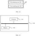
- this application provides a series-parallel switching apparatus, applied to a power conversion circuit, where the power conversion circuit is configured to connect to a load, the power conversion circuit includes two power conversion modules, the two power conversion modules are connected in series or connected in parallel, the power conversion module includes a switch branch, and the apparatus includes: a first obtaining unit, configured to obtain a first voltage between two ends of the load and a maximum output voltage of the power conversion module; and a first switching unit, configured to switch a connection mode of the two power conversion modules based on a current connection mode of the two power conversion modules, the first voltage, the maximum output voltage, and an operating state of the switch branch, where the connection mode includes a series connection and a parallel connection, and the operating state includes a stopping state and a running state.
- the first switching unit is further configured to: determine, based on the current connection mode of the two power conversion modules, the first voltage, and the maximum output voltage, whether the connection mode of the two power conversion modules needs to be switched; and if the connection mode of the two power conversion modules needs to be switched, switch the connection mode of the two power conversion modules based on the operating state of the switch branch.
- the first switching unit is further configured to: under a condition that the current connection mode of the two power conversion modules is the series connection, and the first voltage is less than a difference between the maximum output voltage and a first voltage threshold, determine that the connection mode of the two power conversion modules needs to be switched.
- the first switching unit is further configured to: under a condition that the current connection mode of the two power conversion modules is the parallel connection, and the first voltage is greater than a sum of the maximum output voltage and a second voltage threshold, determine that the connection mode of the two power conversion modules needs to be switched.
- the power conversion circuit further includes a first switch, a second switch, and a third switch that are connected in sequence
- the two power conversion modules include a first power conversion module and a second power conversion module
- the power conversion module further includes an output terminal, where the output terminal is configured to connect to the load.
- a first end of a first branch including the first switch, the second switch, and the third switch is connected to a first end of the output terminal of the first power conversion module, a second end of the first branch is connected to a second end of the output terminal of the second power conversion module, a connection point between the first switch and the second switch is connected to a first end of the output terminal of the second power conversion module, and a connection point between the second switch and the third switch is connected to a second end of the output terminal of the first power conversion module.
- the first switching unit is further configured to: control the first switch, the second switch, and the third switch to switch between on/off states, and control the switch branch to switch the operating state, to switch the connection mode of the two power conversion modules, where the on/off states include turn-on and turn-off.
- the switch branch includes a first switch branch, and the first switch branch is connected to the output terminal.
- the first switching unit is further configured to: under a condition that the connection mode of the two power conversion modules is switched from the parallel connection to the series connection, control the first switch and the third switch to be off, and delay for first duration; apply a first control signal to the first switch branch at an end time of the first duration to control the first switch branch to switch from the stopping state to the running state; and under a condition that a voltage between the first end and the second end of the output terminal of either of the power conversion modules is not greater than a third voltage threshold, control the second switch to be on.
- the power conversion module further includes an input terminal
- the switch branch includes a second switch branch, where the second switch branch is connected to the input terminal, and the input terminal is configured to connect to an external input power supply.
- the first switching unit is further configured to: under a condition that the connection mode of the two power conversion modules is switched from the series connection to the parallel connection, control the second switch to be off, and delay for second duration; apply a second control signal to the second switch branch at an end time of the second duration to control the second switch branch to switch from the stopping state to the running state; and under a condition that a voltage between the first end and the second end of the output terminal of either of the power conversion modules is not less than a fourth voltage threshold, control the first switch and the third switch to be on.
- this application provides a series-parallel switching apparatus, including a memory and a processor coupled to the memory, where the processor is configured to perform, based on instructions stored in the memory, the method according to the second aspect.
- this application provides a charging device, including the power conversion circuit according to the first aspect and/or the series-parallel switching apparatus according to the third aspect or the fourth aspect.
- the charging device is a charging pile or a charger.
- this application provides a computer-readable storage medium, including computer-executable instructions for performing the method according to the second aspect.
- the power conversion circuit provided in this application includes the control unit and two power conversion modules.
- the two power conversion modules need to discharge energy, that is, discharge power.
- the energy discharge loop then can be provided by using the first switch branches in the two power conversion modules. Therefore, the two power conversion modules can discharge energy by using the energy discharge loop. Because no additional discharge branch is added, in contrast to the related art, the costs of the power conversion circuit are lower and the volume is smaller. In addition, there is no need to add an additional discharge branch control process. In comparison with the solution of adding a discharge branch in the related art, there is less difficulty in control.
- the existing solution to controlling the first switch branch may be further simply improved to obtain the solution to controlling the first switch branch to implement the energy discharge process. This helps simplify the control solution in the series-parallel switching process of the two power conversion modules, thereby reducing difficulty in control.
- connection may be a fixed connection, a detachable connection, or an integrated connection, or may be a direct connection, or an indirect connection through an intermediate medium. Persons of ordinary skill in the art can understand specific meanings of the terms in this application based on specific situations.
- a plurality of power conversion modules in a series/parallel structure are usually used for implementation, to improve adaptability of a charging device to different charging objects. Specifically, the plurality of power conversion modules are in a series output state when a large voltage output is required, and the plurality of power conversion modules are in a parallel output state when a low voltage output is required.
- an output voltage of the charging device is an output voltage of a single power conversion module. If the plurality of power conversion modules are connected in series, an output voltage of the charging device is a sum of output voltages of all the power conversion modules.
- the inventors of this application have found that, currently, in the charging device, to keep the output voltage of the charging device substantially unchanged in a series-parallel switching process of the plurality of power conversion modules, the charging device is required to have an energy discharge capability to discharge energy efficiently. For example, assuming that two power conversion modules are disposed in the charging device and that an output voltage of either of the power conversion modules is 500 V, output voltages of the two power conversion modules connected in parallel are 500 V If the two power conversion modules are switched from a parallel connection to a series connection, the output voltage of either of the power conversion modules needs to be reduced to 250 V to keep the output voltage of the charging device substantially unchanged. Therefore, the charging device needs to have an energy discharge capability to reduce the output voltage of either of the power conversion modules from 500 V to 250 V
- the discharge branch may include a switch and a resistor, and the switch connects the resistor to a loop to consume energy by using the resistor, thereby completing an energy discharge process.
- the additional discharge branch added in the foregoing manner not only causes the costs and volume of the charging device to increase, but also requires addition of a discharge branch control process, that is, it causes an increase of difficulty in control and may further cause a decrease of operation efficiency.
- an energy discharge loop may be provided by using a first switch branch in two power conversion modules, to implement an energy discharge process when the two power conversion modules are switched from a parallel connection to a series connection.
- the energy discharge process is implemented only by using the first switch branch in the power conversion module, and there is no need to add an additional discharge branch.
- costs are lower and a volume is smaller.
- an existing solution to controlling the first switch branch may be used for reference, that is, the existing solution to controlling the first switch branch may be simply improved to obtain a solution to controlling the first switch branch to implement the energy discharge process. This helps simplify the control solution in a series-parallel switching process of the two power conversion modules, thereby reducing difficulty in control.
- the power conversion circuit disclosed in this embodiment of this application may be used in a charging device such as a charger or a charging pile, but this is not limited.
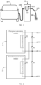
- the application scenario includes an electric vehicle 10, a charging pile 11, and an interface 12.
- the charging pile 11 includes a 1st power conversion module 111, a 2nd power conversion module 112, a power cable 113, and a charging cable 114.
- the power cable 113 is configured to connect to an external input power supply (for example, mains) through the interface 12 (for example, a socket) to obtain an input voltage.
- the 1st power conversion module 111 and the 2nd power conversion module 112 may be connected in series or connected in parallel. For example, in FIG. 1 , the 1st power conversion module 111 and the 2nd power conversion module 112 are connected in parallel.
- the 1st power conversion module 111 and the 2nd power conversion module 112 can convert the input voltage obtained through the interface 12 into a voltage that can be used to charge the electric vehicle 10, and charge the electric vehicle 10 by using the charging cable 114.
- a charging pile is used as an example of a charging device.
- the charging device may alternatively be but is not limited to a vehicular charger, a non-vehicular charger, or the like.
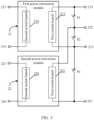
- the power conversion circuit includes a control unit (not shown in the figure) and two power conversion modules, where the two power conversion modules are a first power conversion module 21 and a second power conversion module 22. Either of the power conversion modules includes an output terminal and a first switch branch.
- the first power conversion module 21 includes a first switch branch 211 and an output terminal, and the output terminal of the first power conversion module 21 includes a first end 212 and a second end 213; and the second power conversion module 22 includes a first switch branch 221 and an output terminal, and the output terminal of the second power conversion module 22 includes a first end 222 and a second end 223.
- the first power conversion module 21 and the second power conversion module 22 may be connected in parallel or connected in series.
- the first switch branch 211 of the first power conversion module 21 is connected to the first end 212 and the second end 213 of the output terminal of the first power conversion module 21 respectively
- the first switch branch 221 of the second power conversion module 22 is connected to the first end 222 and the second end 223 of the output terminal of the second power conversion module 22 respectively.
- the output terminal of the first power conversion module 21 and the output terminal of the second power conversion module 22 are both configured to connect to a load.
- the first switch branch 211 of the first power conversion module 21 and the first switch branch 221 of the second power conversion module 22 are both connected to the control unit.
- the first switch branch 211 of the first power conversion module 21 and the first switch branch 221 of the second power conversion module 22 are both controlled by the control unit and switch an operating state according to a first control signal output by the control unit, where the operating state of both the first switch branch 211 of the first power conversion module 21 and the first switch branch 221 of the second power conversion module 22 includes a stopping state and a running state.
- the stopping state means that each switch in the first switch branch 211 of the first power conversion module 21 and the first switch branch 221 of the second power conversion module 22 remains in the current status, that is, no turn-on or turn-off action is performed.
- the running state means that at least one switch in the first switch branch 211 of the first power conversion module 21 and the first switch branch 221 of the second power conversion module 22 is turned on or turned off under the action of the first control signal.
- the first switch branch 211 of the first power conversion module 21 and the first switch branch 221 of the second power conversion module 22 are in the running state, the first switch branch 211 of the first power conversion module 21 and the first switch branch 221 of the second power conversion module 22 can implement energy transfer; conversely, when the first switch branch 211 of the first power conversion module 21 and the first switch branch 221 of the second power conversion module 22 are in the stopping state, the first switch branch 211 of the first power conversion module 21 and the first switch branch 221 of the second power conversion module 22 cannot transfer energy.
- the first power conversion module 21 and the second power conversion module 22 need to switch from a parallel connection to a series connection, the first power conversion module 21 and the second power conversion module 22 need to discharge energy, that is, need to discharge power.
- the first switch branch 211 of the first power conversion module 21 and the first switch branch 221 of the second power conversion module 22 may be controlled by the control unit to switch from the stopping state to the running state to provide an energy discharge loop. In this way, the first power conversion module 21 and the second power conversion module 22 can transfer energy to be discharged, to an electronic component for consumption through the energy discharge loop in an energy transfer mode to implement an energy discharge process.
- the energy discharge process is implemented, and no additional discharge branch is added as in the related art. Therefore, costs of the power conversion circuit can be reduced, and a volume of the power conversion circuit can be reduced.
- an existing solution to controlling the first switch branch may be further simply improved to obtain a solution to controlling the first switch branch to implement the energy discharge process. Therefore, the control solution in the series-parallel switching process of the two power conversion modules can be simplified, and this helps reduce difficulty in control.
- either of the power conversion modules further includes an input terminal and a second switch branch.
- the first power conversion module 21 further includes a second switch branch 214 and an input terminal, and the input terminal of the first power conversion module 21 includes a first end 215 and a second end 216; and the second power conversion module 22 further includes a second switch branch 224 and an input terminal, and the input terminal of the second power conversion module 22 includes a first end 225 and a second end 226.
- the second switch branch 214 is connected to the first end 215 and the second end 216 of the input terminal of the first power conversion module 21 respectively, and the second switch branch 224 is connected to the first end 225 and the second end 226 of the input terminal of the second power conversion module 22 respectively.
- the input terminal of the first power conversion module 21 and the input terminal of the second power conversion module 22 are both configured to connect to the external input power supply.
- the second switch branch 214 of the first power conversion module 21 and the second switch branch 224 of the second power conversion module 22 are both connected to the control unit.
- the second switch branch 214 of the first power conversion module 21 and the second switch branch 224 of the second power conversion module 22 are both controlled by the control unit and switch an operating state according to a second control signal output by the control unit, where the operating state of both the second switch branch 214 of the first power conversion module 21 and the second switch branch 224 of the second power conversion module 22 includes a stopping state and a running state.
- the stopping state means that each switch in the second switch branch 214 of the first power conversion module 21 and the second switch branch 224 of the second power conversion module 22 remains in the current status, that is, no turn-on or turn-off action is performed.
- the running state means that at least one switch in the second switch branch 214 of the first power conversion module 21 and the second switch branch 224 of the second power conversion module 22 is turned on or turned off under the action of the second control signal.
- the second switch branch 214 of the first power conversion module 21 and the second switch branch 224 of the second power conversion module 22 are in the running state, the second switch branch 214 of the first power conversion module 21 and the second switch branch 224 of the second power conversion module 22 can implement energy transfer; conversely, when the second switch branch 214 of the first power conversion module 21 and the second switch branch 224 of the second power conversion module 22 are in the stopping state, the second switch branch 214 of the first power conversion module 21 and the second switch branch 224 of the second power conversion module 22 cannot transfer energy.
- the first power conversion module 21 and the second power conversion module 22 need to switch from the series connection to the parallel connection, energy needs to be replenished for the first power conversion module 21 and the second power conversion module 22, that is, charging is required.
- the first power conversion module 21 and the second power conversion module 22 are connected in series and that output voltages of the first power conversion module 21 and the second power conversion module 22 are 250 V
- the output voltages of the first power conversion module 21 and the second power conversion module 22 need to be increased to 500 V
- the second switch branch 214 and the second switch branch 224 may be controlled by the control unit to switch from the stopping state to the running state to provide a charge loop.
- the external input power supply can charge the output terminal of the first power conversion module 21 and the output terminal of the second power conversion module 22 through the charge loop to increase a voltage of the output terminal of the first power conversion module 21 and a voltage of the output terminal of the second power conversion module 22, thereby completing the switching of the first power conversion module 21 and the second power conversion module 22 from the series connection to the parallel connection.
- the costs are lower and the volume is smaller.
- an existing solution to controlling the second switch branch may be further simply improved to obtain a solution to controlling the second switch branch to charge the output terminal of the first power conversion module 21 and the output terminal of the second power conversion module 22, that is, the difficulty in control can be reduced.
- the power conversion circuit further includes a first switch S1, a second switch S2, and a third switch S3 that are connected in sequence.
- the first switch S1, the second switch S2, and the third switch S3 are connected in series.
- a first end of a first branch including the first switch S1, the second switch S2, and the third switch S3 is connected to the first end 212 of the output terminal of the first power conversion module 21, and the second end of the first branch is connected to the second end 223 of the output terminal of the second power conversion module 22.
- a connection point between the first switch S 1 and the second switch S2 is connected to the first end 222 of the output terminal of the second power conversion module 22, and a connection point between the second switch S2 and the third switch S3 is connected to the second end 213 of the output terminal of the first power conversion module 21.
- the first switch S1, the second switch S2, and the third switch S3 are configured to implement series-parallel switching of the first power conversion module 21 and the second power conversion module 22.
- the first switch S 1 and the third switch S3 are on and the second switch S2 is off, the first end 212 of the output terminal of the first power conversion module 21 is connected to the first end 222 of the output terminal of the second power conversion module 22, and the second end 213 of the output terminal of the first power conversion module 21 is connected to the second end 223 of the output terminal of the second power conversion module 22.
- the first power conversion module 21 and the second power conversion module 22 are connected in parallel.
- the second switch S2 When the second switch S2 is on and the first switch S 1 and the third switch S3 are off, the second end 213 of the output terminal of the first power conversion module 21 is connected to the first end 223 of the output terminal of the second power conversion module 22. In this case, the first power conversion module 21 and the second power conversion module 22 are connected in series.
- each switch in this embodiment of this application may be any electronic component that can serve as a switch, such as a metal-oxide-semiconductor field-effect transistor MOSFET, an insulated gate bipolar transistor IGBT, a silicon controlled rectifier SCR, a gate turn-off thyristor GTO, or a giant transistor GTR, or any commonly used switch, such as a contactor, a relay, a time-delay switch, a photoelectric switch, a tact switch, or a proximity switch, or a variety of combinations of the foregoing switches.
- a metal-oxide-semiconductor field-effect transistor MOSFET an insulated gate bipolar transistor IGBT
- a silicon controlled rectifier SCR a gate turn-off thyristor GTO
- GTR giant transistor GTR
- any commonly used switch such as a contactor, a relay, a time-delay switch, a photoelectric switch, a tact switch, or a proximity switch, or a variety of combinations
- FIG. 4 is a flowchart of a series-parallel switching method according to an embodiment of this application.
- the series-parallel switching method is applied to a power conversion circuit, where the power conversion circuit is configured to connect to a load, the power conversion circuit includes two power conversion modules, the two power conversion modules are connected in series or connected in parallel, and the power conversion module includes a switch branch.
- the series-parallel switching method includes the following steps.
- Step 41 Obtain a first voltage between two ends of a load and a maximum output voltage of the power conversion module.
- the load is an electronic component connected to both ends of an output power supply of the power conversion circuit; it is an apparatus for consuming electric energy, that is, an apparatus using electric energy for operation, and may also be referred to as an electric apparatus.
- the first voltage between both ends of the load is an operation voltage required by the load for normal operation.
- the maximum output voltage of the power conversion module is a rated output voltage of the power conversion module.
- Step 42 Switch a connection mode of the two power conversion modules based on a current connection mode of the two power conversion modules, the first voltage, the maximum output voltage, and an operating state of the switch branch.
- the connection mode of the two power conversion modules includes a series connection and a parallel connection.
- the operating state of the switch branch includes a stopping state and a running state. Similarly, when the switch branch is in the stopping state, the switch branch does not transfer energy, and when the switch branch is in the running state, the switch branch transfers energy.
- a series-parallel switching process of the two power conversion modules is only related to parameters of the two power conversion modules and the switch branch in the power conversion module, and there is no need to add an additional electronic component. Therefore, the power conversion circuit can have lower costs and a smaller volume.
- the switch branch in the power conversion module is used, and an existing control solution can be improved to obtain a solution to controlling the switch branch in the series-parallel switching process. This helps simplify the control solution in the series-parallel switching process and reduce difficulty in control.
- the process of switching a connection mode of the two power conversion modules based on a current connection mode of the two power conversion modules, the first voltage, the maximum output voltage, and an operating state of the switch branch in step 42 includes the following steps.
- Step 51 Determine, based on the current connection mode of the two power conversion modules, the first voltage, and the maximum output voltage, whether the connection mode of the two power conversion modules needs to be switched.
- Step 52 If the connection mode of the two power conversion modules needs to be switched, switch the connection mode of the two power conversion modules based on the operating state of the switch branch.
- connection mode of the two power conversion modules Before the connection mode of the two power conversion modules is switched, it is first necessary to determine whether switching is required. Based on the first voltage required by the load, an output voltage of the power conversion module, and the current connection mode of the two power conversion modules, it can be more accurately determined whether the current connection mode of the two power conversion modules can enable the power conversion modules to have higher operation efficiency, and whether a voltage that can be provided can satisfy the first voltage required by the load. Therefore, it can be more accurately determined whether switching is required. This helps reduce a probability of wrong switching and provide operation stability of the power conversion circuit.
- the connection mode of the two power conversion modules needs to be switched.
- the two power conversion modules include a first power conversion module and a second power conversion module.
- a total voltage output by the power conversion circuit is a sum of an output voltage of the first power conversion module and an output voltage of the second power conversion module.
- the first voltage V1 required by the load is less than the difference between the maximum output voltage Vmax of either of the power conversion modules and the first voltage threshold Vh1, that is, V1 ⁇ Vmax - Vh1.
- the first voltage threshold Vh1 is greater than 0.
- the maximum output voltage Vmax of either of the power conversion modules is greater than the first voltage V1, and a single power conversion module can already meet the operation voltage required by the load.
- the two power conversion modules can be switched from the series connection to the parallel connection, so that an actual output voltage of a single power conversion module is closer to the maximum output voltage of the power conversion module. This helps improve conversion efficiency and conversion accuracy of the power conversion module and therefore can improve operation stability of the power conversion circuit.
- the first voltage threshold may be set based on an actual application. This is not limited in this embodiment of this application. For example, in an embodiment, any value, such as 10 V, within a range of [5 V, 10 V] may be selected as the first voltage threshold.
- the connection mode of the two power conversion modules needs to be switched.
- the two power conversion modules include a first power conversion module and a second power conversion module.
- an output voltage of the first power conversion module is equal to an output voltage of the second power conversion module, that is, a total voltage output by the power conversion circuit is the output voltage of either of the power conversion modules.
- the first voltage V1 required by the load is greater than the sum of the maximum output voltage Vmax of either of the power conversion modules and the second voltage threshold Vh2, that is, V1 > Vmax + Vh2.
- the second voltage threshold Vh2 is greater than 0.
- the maximum output voltage Vmax of either of the power conversion modules is less than the first voltage V1, that is, the total voltage output by the power conversion circuit cannot meet the operation voltage required by the load.
- the two power conversion modules can be switched from the parallel connection to the series connection, so that the total voltage output by the power conversion circuit is the sum of the output voltages of the two power conversion modules. In other words, the total voltage output by the power conversion circuit is increased to meet the first voltage required by the load. This helps maintain operation stability of the load.
- the second voltage threshold may be set based on an actual application and that the second voltage threshold may be the same as or different from the first voltage threshold. This is not limited in this embodiment of this application. For example, in an embodiment, any value, such as 5 V, within a range of [5 V, 10 V] may be selected as the second voltage threshold.
- the power conversion circuit further includes a first switch S 1, a second switch S2, and a third switch S3 that are connected in sequence.
- the power conversion module further includes an output terminal.
- the output terminal of the first power conversion module 21 includes a first end 212 and a second end 213, and the output terminal of the second power conversion module 22 includes a first end 222 and a second end 223.
- a connection relationship between the first switch S1, the second switch S2, the third switch S3 and the output terminal of the power conversion module has been described in the foregoing embodiment. Details are not described again herein.
- the switching the connection mode of the two power conversion modules based on the operating state of the switch branch in step 52 may specifically include the following step.
- Step 61 Control the first switch S1, the second switch S2, and the third switch S3 to switch between on/off states, and control the switch branch to switch the operating state, to switch the connection mode of the two power conversion modules.
- the on/off states of the switch branch include turn-on and turn-off.
- controlling the first switch S1, the second switch S2, and the third switch S3 to switch between the on/off states may be used for switching the two power conversion modules from the series connection to the parallel connection, or used for switching the two power conversion modules from the parallel connection to the series connection.
- controlling the switch branch to switch the operating state it is possible to provide an energy discharge loop or a charge loop in the series-parallel switching process of the two power conversion modules. It can be learned that the series-parallel switching process of the two power conversion modules can be implemented by controlling the first switch S 1, the second switch S2, and the third switch S3 to switch between the on/off states and controlling the switch branch to switch the operating state. Moreover, in this process, there is no need to add an additional discharge branch or charge branch.
- an existing solution to controlling the switch branch may be simply improved to obtain a solution to controlling the switch branch to implement an energy discharge process or a charge process. This helps simplify the control solution in the series-parallel switching process and reduce difficulty in control.
- the switch branch of the power conversion circuit includes a first switch branch, and the first switch branch is connected to the output terminal of the power conversion module.
- the power conversion circuit may be shown in FIG. 3 , the first power conversion module 21 includes a first switch branch 211, and the second power conversion module 22 includes a first switch branch 221.
- the first switch branch 211 is connected to the first end 212 and the second end 213 of the output terminal of the first power conversion module 21 respectively, and the first switch branch 221 is connected to the first end 222 and the second end 223 of the output terminal of the second power conversion module 22 respectively.
- controlling the first switch, the second switch, and the third switch to switch between on/off states, and controlling the switch branch to switch the operating state, to switch the connection mode of the two power conversion modules in step 61 may specifically include the following steps.
- Step 71 Under a condition that the connection mode of the two power conversion modules is switched from the parallel connection to the series connection, control the first switch and the third switch to be off, and delay for first duration.
- Step 72 Apply a first control signal to the first switch branch at an end time of the first duration to control the first switch branch to switch from the stopping state to the running state.
- Step 73 Under a condition a voltage between the first end and the second end of the output terminal of either of the power conversion modules is not greater than a third voltage threshold, control the first switch to be on.
- the power conversion circuit shown in FIG. 3 is used as an example for description.
- the current connection mode of the two power conversion modules is the parallel connection
- the first switch S 1 and the third switch S3 are on
- the second switch S2 is off.
- the first duration is used to determine that both the first switch S1 and the third switch S3 are already off. It can be understood that the first duration may be set based on characteristics of actual electronic components selected by a user as the first switch S1 and the third switch S3. This is not limited in this embodiment of this application.
- relays are selected as both the first switch S1 and the third switch S3.
- a relay can perform a complete turn-on or turn-off action.
- the first duration may be set to 100 ms.
- the first control signal is applied to the first switch branch 211 of the first power conversion module 21 and the first switch branch 221 of the second power conversion module 22 at the end time of the first duration, so that the first switch branch 211 of the first power conversion module 21 and the first switch branch 221 of the second power conversion module 22 are switched to the running state to provide an energy discharge loop.
- the first control signal is a signal for controlling the first switch branch 211 of the first power conversion module 21 and the first switch branch 221 of the second power conversion module 22 to switch the operating state. Both the two power conversion modules then discharge energy through the energy discharge loop.
- energy of the first power conversion module 21 is transferred from the output terminal of the first power conversion module 21 to the first switch branch 211, and energy of the second power conversion module 22 is transferred from the output terminal of the second power conversion module 22 to the first switch branch 221.
- the voltage between the first end 212 and the second end 213 of the output terminal of the first power conversion module 21 is decreased, and the voltage between the first end 222 and the second end 223 of the output terminal of the second power conversion module 22 is also decreased.
- the second switch S2 is then controlled to be on, thereby completing the switching process of switching from the parallel connection to the series connection.
- the first switch branch in either of the power conversion modules is used skillfully to discharge energy, and there is no need to add an additional discharge branch. Therefore, the costs can be reduced, and the volume can be reduced.
- the existing control solution can be used for reference, to obtain a solution to controlling the first switch branch to implement the energy discharge process. This helps reduce difficulty in control.
- the third voltage threshold may be set based on an actual application. This is not limited in this embodiment of this application. In an implementation, the third voltage threshold may be set to half the voltage Vo1 output by either of the power conversion modules when the two power conversion modules are connected in parallel, so that a value of the total voltage output by the power conversion circuit is equal to a value of the voltage Vo1 when the two power conversion modules are switched to the series connection.
- the switch branch in the power conversion circuit includes a second switch branch, and the power conversion module further includes an input terminal, where the second switch branch is connected to the input terminal of the power conversion module.
- the power conversion circuit may be shown in FIG. 3 , the first power conversion module 21 includes a second switch branch 214, and the second power conversion module 22 includes a second switch branch 224.
- the second switch branch 214 of the first power conversion module 21 is connected to a first end 215 and a second end 216 of the input terminal of the first power conversion module 21 respectively, and the second switch branch 224 of the second power conversion module 22 is connected to a first end 225 and a second end 226 of the input terminal of the second power conversion module 22 respectively.
- controlling the first switch, the second switch, and the third switch to switch between on/off states, and controlling the switch branch to switch the operating state, to switch the connection mode of the two power conversion modules in step 61 may specifically include the following steps.
- Step 81 Under a condition the connection mode of the two power conversion modules is switched from the series connection to the parallel connection, control the second switch to be off, and delay for second duration.
- Step 82 Apply a second control signal to the second switch branch at an end time of the second duration to control the second switch branch to switch from the stopping state to the running state.
- Step 83 Under a condition a voltage between the first end and the second end of the output terminal of either of the power conversion modules is not less than a fourth voltage threshold, control the first switch and the third switch to be on.
- the power conversion circuit shown in FIG. 3 is also used as an example for description.
- the second switch S2 is on, and the first switch S1 and the third switch S3 are off.
- the second duration is used to determine that the second switch S2 is already off. It can be understood that the second duration may be set based on characteristics of an actual electronic component selected by the user as the second switch S2. This is not limited in this embodiment of this application. For example, in an embodiment, if a relay is also selected as the second switch S2, the second duration may also be set to 100 ms.
- the second control signal is applied to the second switch branch 214 of the first power conversion module 21 and the second switch branch 224 of the second power conversion module 22 at the end time of the second duration, so that the second switch branch 214 of the first power conversion module 21 and the second switch branch 224 of the second power conversion module 22 are switched to the running state to provide a charge loop.
- the second control signal is a signal for controlling the second switch branch 214 of the first power conversion module 21 and the second switch branch 224 of the second power conversion module 22 to switch the operating state.
- Energy of the first power conversion module 21 is then transferred from the input terminal of the first power conversion module 21 to the output terminal of the first power conversion module 21 through the second switch branch 214, and energy of the second power conversion module 22 is transferred from the input terminal of the second power conversion module 22 to the output terminal of the second power conversion module 22 through the second switch branch 224.
- the voltage between the first end 212 and the second end 213 of the output terminal of the first power conversion module 21 is increased, and the voltage between the first end 222 and the second end 223 of the output terminal of the second power conversion module 22 is also increased.
- the voltage between the first end 212 and the second end 213 of the output terminal of the first power conversion module 21 is not less than (that is, greater than or equal to) the fourth voltage threshold, while the voltage between the first end 222 and the second end 223 of the output terminal of the second power conversion module 22 is not less than (that is, greater than or equal to) the fourth voltage threshold.
- the first switch S1 and the third switch S3 are then controlled to be on, thereby completing the switching process of switching from the series connection to the parallel connection.
- the second switch branch in either of the power conversion modules is also used to implement the process of charging the output terminal of either of the power conversion modules, and no additional charge branch is added. Therefore, the costs can be reduced, and the volume can be reduced.
- the existing control solution can be used for reference, to obtain a solution to controlling the second switch branch to implement the charge process. This helps reduce difficulty in control.
- the fourth voltage threshold may be set based on an actual application. This is not limited in this embodiment of this application.
- the fourth voltage threshold may be set to the total voltage Vo2 output by the power conversion circuit when the two power conversion modules are connected in series, so that a value of the voltage output by either of the power conversion modules is equal to a value of the total voltage Vo2 when the two power conversion modules are switched to the parallel connection.
- a loop current that may be generated during the parallel connection of the two power conversion modules can be reduced, and a risk of damage to each electronic component of the power conversion module can be reduced. This helps extend a service life of each electronic component, to improve stability of the power conversion circuit.
- FIG. 9 is a schematic diagram of a circuit structure corresponding to the first power conversion module 21 in the power conversion circuit shown in FIG. 3 according to an embodiment of this application.
- the first switch branch 211 of the first power conversion module 21 includes a first switching transistor Q1, a second switching transistor Q2, a third switching transistor Q3, and a fourth switching transistor Q4. Moreover, the first switch branch 211 is connected to the load through the output terminal, and the load is, for example, a third capacitor C3 and a first resistor R1 that are connected in parallel.
- the second switch branch 214 of the first power conversion module 21 includes a fifth switching transistor Q5, a sixth switching transistor Q6, a seventh switching transistor Q7, and an eighth switching transistor Q8. Moreover, the second switch branch 214 is connected to an input power supply U1 through the input terminal.
- the first power conversion module 21 further includes a resonant cavity 217, where the resonant cavity 217 is connected between the first switch branch 211 and the second switch branch 214, and the resonant cavity 217 is used to implement transfer of AC energy.
- a circuit of the second power conversion module 22 and the first power conversion module 21 may both use the circuit structure shown in FIG. 9 .
- control modes of the first switch branches in different power conversion modules may be the same, and control modes of the second switch branches may also be the same. Therefore, only the first power conversion module 21 is used as an example herein.
- An actual application process of the second power conversion module 22 is similar to that of the first power conversion module 21, and is within the scope easily understood by persons skilled in the art. Details are not described herein again.
- FIG. 10 shows control signals of the first switch, the second switch, the third switch, and the first switch branch in the power conversion circuit in a process of switching the two power conversion modules from the parallel connection to the series connection.
- a horizontal coordinate t represents time and a vertical coordinate represents a level.
- a curve L11 is a control signal of the first switch S1 and the third switch S3; a curve L21 is a control signal of the second switch S2; a curve L31 and a curve L41 are control signals of the first switch branch 211.
- the curve L31 may be a control signal of the first switching transistor Q1 and the fourth switching transistor Q4, the curve L41 is a control signal of the second switching transistor Q2 and the third switching transistor Q3, or conversely, if the curve L41 may be a control signal of the first switching transistor Q1 and the fourth switching transistor Q4, the curve L31 is a control signal of the second switching transistor Q2 and the third switching transistor Q3. It should be understood that the first control signal in the foregoing embodiment includes the curve L31 and the curve L41.
- the control signal of the first switch S1 and the third switch S3 is a high level signal, and in this case, the first switch S1 and the third switch S3 are on; the control signal of the second switch S2 is a low level signal, and in this case, the second switch S2 is off, and the two power conversion modules are connected in parallel.
- the process of switching the two power conversion modules to the series connection starts at the time 111.
- the control signal of the first switch S1 and the third switch S3 is pulled down to a low level, that is, the first switch S1 and the third switch S3 are turned off, and the process delays for the first duration.
- the first control signal is applied to the first switch branch 211 at the end time of the first duration, that is, a time t21.
- the first control signal is a PWM waveform with a fixed switching frequency and duty cycle, applied to the first switching transistor Q1, the second switching transistor Q2, the third switching transistor Q3, and the fourth switching transistor Q4.
- a same PWM waveform (such as the curve L31) is applied to the first switching transistor Q1 and the fourth switching transistor Q4
- a same PWM waveform (such as the curve L41) is applied to the second switching transistor Q2 and the fourth switching transistor Q4, and the curve L31 and the curve L41 should have a complementary relationship.
- the first switch branch 211 is switched from the stopping state to the running state to transfer energy of the first power conversion module 21 from right to left, that is, from the output terminal to the input terminal, and energy of the first power conversion module 21 is reduced. Similarly, in this case, energy of the second power conversion module 22 is also reduced.
- the control signal of the second switch S2 is pulled up to a high level, that is, the second switch S2 is turned on, thereby completing the switching of the two power conversion modules from the parallel connection to the series connection.
- FIG. 11 shows control signals of the first switch, the second switch, the third switch, and the second switch branch in the power conversion circuit in a process of switching the two power conversion modules from the series connection to the parallel connection.
- a horizontal coordinate t represents time and a vertical coordinate represents a level.
- a curve L12 is a control signal of the first switch S 1 and the third switch S3; a curve L22 is a control signal of the second switch S2; a curve L32 and a curve L42 are control signals of the second switch branch 214.
- the curve L32 may be a control signal of the fifth switching transistor Q5 and the eighth switching transistor Q8, the curve L42 is a control signal of the sixth switching transistor Q6 and the seventh switching transistor Q7, or conversely, if the curve L42 may be a control signal of the fifth switching transistor Q5 and the eighth switching transistor Q8, the curve L32 is a control signal of the sixth switching transistor Q6 and the seventh switching transistor Q7.
- the second control signal in the foregoing embodiment includes the curve L32 and the curve L42.
- the control signal of the first switch S1 and the third switch S3 is a low level signal, and in this case, the first switch S1 and the third switch S3 are off; the control signal of the second switch S2 is a high level signal, and in this case, the second switch S2 is on, and the two power conversion modules are connected in series. Switching of the two power conversion modules to the parallel connection starts at the time t12. In this case, the control signal of the second switch S2 is pulled down to a low level, that is, the second switch S2 is turned off, and the process delays for the second duration.
- the second control signal is applied to the second switch branch 214 at the end time of the second duration, that is, a time t22.
- the second control signal is a PWM waveform with a fixed switching frequency and duty cycle, applied to the fifth switching transistor Q5, the sixth switching transistor Q6, the seventh switching transistor Q7, and the eighth switching transistor Q8.
- a same PWM waveform (such as the curve L32) is applied to the fifth switching transistor Q5 and the eighth switching transistor Q8, a same PWM waveform (such as the curve L42) is applied to the sixth switching transistor Q6 and the seventh switching transistor Q7, and the curve L32 and curve L42 should have a complementary relationship.
- the second switch branch 214 is switched from the stopping state to the running state to transfer energy of the first power conversion module 21 from left to right, that is, from the input terminal to the output terminal, and energy of the first power conversion module 21 is increased. Similarly, in this case, energy of the second power conversion module 22 is also increased.
- the control signal of the first switch S1 and the third switch S3 is pulled up to a high level, so that the first switch S1 and the third switch S3 are turned on, thereby completing the switching of the two power conversion modules from the series connection to the parallel connection.
- FIG. 12 is a schematic structural diagram of a series-parallel switching apparatus according to an embodiment of this application.
- the apparatus is applied to a power conversion circuit.
- the series-parallel switching apparatus 1200 includes a first obtaining unit 1201 and a first switching unit 1202.
- the first obtaining unit 1201 is configured to obtain a first voltage between two ends of a load and a maximum output voltage of a power conversion module.
- the first switching unit 1202 is configured to switch a connection mode of two power conversion modules based on a current connection mode of the two power conversion modules, the first voltage, the maximum output voltage, and an operating state of a switch branch, where the connection mode includes a series connection and a parallel connection, and the operating state includes a stopping state and a running state.
- the first switching unit 1202 is further configured to: determine, based on the current connection mode of the two power conversion modules, the first voltage, and the maximum output voltage, whether the connection mode of the two power conversion modules needs to be switched; and if the connection mode of the two power conversion modules needs to be switched, switch the connection mode of the two power conversion modules based on the operating state of the switch branch.
- the first switching unit 1202 is further configured to: under a condition the current connection mode of the two power conversion modules is the series connection, and the first voltage is less than a difference between the maximum output voltage and a first voltage threshold, determine that the connection mode of the two power conversion modules needs to be switched.
- the first switching unit 1202 is further configured to: under a condition the current connection mode of the two power conversion modules is the parallel connection, and the first voltage is greater than a sum of the maximum output voltage and a second voltage threshold, determine that the connection mode of the two power conversion modules needs to be switched.
- the first switching unit 1202 is further configured to: control a first switch, a second switch, and a third switch to switch between on/off states, and control the switch branch to switch the operating state, to switch the connection mode of the two power conversion modules, where the on/off states include turn-on and turn-off.
- the first switching unit 1202 is further configured to: under a condition the connection mode of the two power conversion modules is switched from the parallel connection to the series connection, control the first switch and the third switch to be off, and delay for first duration; apply a first control signal to a first switch branch at an end time of the first duration to control the first switch branch to switch from the stopping state to the running state; and under a condition a voltage between a first end and a second end of an output terminal of either of the power conversion modules is not greater than a third voltage threshold, control the second switch to be on.
- the first switching unit 1202 is further configured to: under a condition the connection mode of the two power conversion modules is switched from the series connection to the parallel connection, control the second switch to be off, and delay for second duration; apply a second control signal to a second switch branch at an end time of the second duration to control the second switch branch to switch from the stopping state to the running state; and under a condition a voltage between the first end and the second end of the output terminal of either of the power conversion modules is not less than a fourth voltage threshold, control the first switch and the third switch to be on.
- FIG. 13 is a schematic structural diagram of a series-parallel switching apparatus according to an embodiment of this application.
- the series-parallel switching apparatus 1300 includes one or more processors 1301 and a memory 1302.
- One processor 1301 is used as an example in FIG. 13 .
- the processor 1301 and the memory 1302 may be connected to each other by using a bus or by other means, for example, connected by using a bus in FIG. 13 .
- the memory 1302 may be configured to store non-volatile software programs, non-volatile computer-executable programs, and modules, such as program instructions/modules corresponding to the series-parallel switching method in the embodiments of this application (such as the units described in FIG. 12 ).
- the processor 1301 executes various functional applications and data processing in the series-parallel switching apparatus, that is, implements the series-parallel switching method in the foregoing method embodiments and functions of the units in the foregoing apparatus embodiment.
- the memory 1302 may include a high-speed random access memory, and may further include a non-volatile memory, for example, at least one disk storage device, a flash memory device, or other non-volatile solid-state storage devices.
- the memory 1302 may optionally include a memory that is remotely disposed relative to the processor 1301, and the remote memory may be connected to the processor 1301 through a network. Examples of the network include but are not limited to the Internet, corporate intranet, local area network, mobile communication network, and a combination thereof.
- the program instructions/modules are stored in the memory 1302.
- the program instructions/modules are executed by the one or more processors 1301, the series-parallel switching method in any one of the method embodiments is performed. For example, steps shown in FIG. 4, FIG. 5 , FIG. 6, FIG. 7 , and FIG. 8 are performed, or functions of the units in FIG. 12 may be implemented.
- An embodiment of this application further provides a charging device, including the power conversion circuit according to any one of the foregoing embodiments and/or the series-parallel switching apparatus according to any one of the foregoing embodiments.
- the charging device is a charging pile or a charger.
- An embodiment of this application further provides a non-volatile computer storage medium, where the computer storage medium stores computer-executable instructions, and when the computer-executable instructions are executed by one or more processors, the one or more processors may be enabled to perform the series-parallel switching method according to any one of the foregoing method embodiments. For example, steps shown in FIG. 4, FIG. 5 , FIG. 6, FIG. 7 , and FIG. 8 are performed, or functions of the units in FIG. 12 may be implemented.
- Modules or units described as separate components may or may not be physically separate. Parts shown as modules or units may be or may not be physical units, and may be located in one place, or may be distributed in a plurality of network modules or units. Some or all of the modules may be selected based on an actual requirement, to achieve the objectives of the solutions in the embodiments.
- each implementation can be implemented by using software in combination to a universal hardware platform, or by using hardware only.
- the technical solutions substantially or parts making contributions to the related art may be embodied in a form of a software product, and the software product may be stored in a computer-readable storage medium, such as a ROM/RAM, a magnetic disk, or an optical disc, and includes several instructions for instructing a computer device (which may be a personal computer, a server, a network device, or the like) to perform the methods described in the embodiments or some parts of the embodiments.
Landscapes
- Engineering & Computer Science (AREA)
- Power Engineering (AREA)
- Transportation (AREA)
- Mechanical Engineering (AREA)
- Charge And Discharge Circuits For Batteries Or The Like (AREA)
- Dc-Dc Converters (AREA)
- Direct Current Feeding And Distribution (AREA)
Abstract
Description
- This application relates to the field of charging technologies, and in particular, to a series-parallel switching method and apparatus, a power conversion circuit, and an electronic device.
- In recent years, a quantity of motor vehicles in China has increased significantly, urban traffic congestion has increased, and automobile exhaust has become a main source of urban air pollution. To alleviate air pollution and reduce environmental problems caused by traditional fuel automobile exhaust, electric vehicle technologies are advancing rapidly and national policies are published to promote development, accompanied by a rapid increase of a new energy vehicle population in the market. Charging devices such as charging piles or vehicular chargers are basic facilities for new energy vehicles. Construction of the charging devices has become an important task to promote transformation and upgrade of vehicles in China and assist in green transportation.
- In addition, as electric vehicles are continuously diversified, required charging voltages also change continuously. To broaden an output voltage range of a charging pile and reduce costs while improving efficiency, a plurality of power conversion modules in a series/parallel structure are usually used for implementation, to improve adaptability of a charging device to different charging objects. Specifically, the plurality of power conversion modules are in a series output state when a large voltage output is required, and the plurality of power conversion modules are in a parallel output state when a low voltage output is required.
- However, in the prior art, when the plurality of power conversion modules are to be switched from a parallel connection to a series connection, usually, an additional module needs to be added to assist in completing the switching process, resulting in higher costs and a larger volume.
- This application is intended to provide a series-parallel switching method and apparatus, a power conversion circuit, and an electronic device. In this application, a series-parallel switching process can be implemented without adding an additional module, so that the power conversion circuit can have lower costs and a smaller volume.
- To achieve the foregoing objective, according to a first aspect, this application provides a power conversion circuit. The circuit includes a control unit and two power conversion modules. The two power conversion modules are connected in series or connected in parallel. Either of the power conversion modules includes an output terminal and a first switch branch, where the first switch branch is connected to the output terminal, and the output terminal is configured to connect to a load. The first switch branch is connected to the control unit, and the first switch branch is configured to switch an operating state according to a first control signal output by the control unit, to provide an energy discharge loop when the two power conversion modules are switched from a parallel connection to a series connection, where the operating state includes a stopping state and a running state.
- When the two power conversion modules are switched from the parallel connection to the series connection, the two power modules need to discharge energy; that is, discharge power. Energy then can be discharged by using the energy discharge loop provided by the first switch branches in the two power conversion modules. Because no additional discharge branch is added, in contrast to the related art, costs are lower and a volume is smaller. In addition, there is no need to add an additional discharge branch control process. In comparison with a solution of adding a discharge branch as in the related art, there is less difficulty in control. Moreover, an existing solution to controlling the first switch branch may be further simply improved to obtain a solution to controlling the first switch branch to implement an energy discharge process. This helps simplify the control solution in a series-parallel switching process of the two power conversion modules, thereby reducing difficulty in control.
- In an optional implementation, the power conversion module further includes an input terminal and a second switch branch. The second switch branch is connected to the input terminal, and the input terminal is configured to connect to an external input power supply. The second switch branch is connected to the control unit, and the second switch branch is configured to switch the operating state according to a second control signal output by the control unit, to charge the output terminal based on the input power supply when the two power conversion modules are switched from the series connection to the parallel connection.
- When the two power conversion modules are switched from the series connection to the parallel connection, energy needs to be replenished for the two power modules, that is, charging is required. The operating state of the second switch branch in the two power conversion modules then may be switched, so that the output terminal of the two power conversion modules is charged by using the input power supply. Similarly, because there is no need to add an additional charge branch, the costs are lower and the volume is smaller. In addition, on one hand, there is no need to add an additional discharge branch control process; on the other hand, an existing solution to controlling the first switch branch may be further simply improved to obtain a solution to controlling the first switch branch to implement an energy discharge process. Therefore, the control solution in the series-parallel switching process of the two power conversion modules can be simplified, and this helps reduce difficulty in control.
- In an optional implementation, the power conversion circuit further includes a first switch, a second switch, and a third switch that are connected in sequence. The two power conversion modules include a first power conversion module and a second power conversion module. A first end of a first branch including the first switch, the second switch, and the third switch is connected to a first end of the output terminal of the first power conversion module, a second end of the first branch is connected to a second end of the output terminal of the second power conversion module, a connection point between the first switch and the second switch is connected to a first end of the output terminal of the second power conversion module, and a connection point between the second switch and the third switch is connected to a second end of the output terminal of the first power conversion module. If the first switch and the third switch are configured as on and the second switch is configured as off, the two power conversion modules are connected in parallel. If the second switch is configured as on and the first switch and the third switch are configured as off, the two power conversion modules are connected in series.
- The first switch, the second switch, and the third switch are configured to implement series-parallel switching of the two power conversion modules. When the first switch and the third switch are on and the second switch is off, the first end of the output terminal of the first power conversion module is connected to the first end of the output terminal of the second power conversion module, and the second end of the output terminal of the first power conversion module is connected to the second end of the output terminal of the second power conversion module. In this case, the two power conversion modules are connected in parallel. When the second switch is on and the first switch and the third switch are off, the second end of the output terminal of the first power conversion module is connected to the first end of the output terminal of the second power conversion module. In this case, the two power conversion modules are connected in series.
- According to a second aspect, this application provides a series-parallel switching method, applied to a power conversion circuit, where the power conversion circuit is configured to connect to a load, the power conversion circuit includes two power conversion modules, the two power conversion modules are connected in series or connected in parallel, and the power conversion module includes a switch branch. The series-parallel switching method includes: obtaining a first voltage between two ends of the load and a maximum output voltage of the power conversion module; and switching a connection mode of the two power conversion modules based on a current connection mode of the two power conversion modules, the first voltage, the maximum output voltage, and an operating state of the switch branch, where the connection mode includes a series connection and a parallel connection, and the operating state includes a stopping state and a running state.
- In the power conversion circuit, when series-parallel switching of the two power conversion modules is required, switching may be implemented based on the current connection mode of the two power conversion modules, the first voltage, the maximum output voltage, and the operating state of the switch branch. In this case, a series-parallel switching process of the two power conversion modules is only related to parameters of the two power conversion modules and the switch branch, and there is no need to add an additional electronic component or the like. Therefore, the power conversion circuit can have lower costs and a smaller volume. In addition, the switch branch in the power conversion module is used, and an existing control solution can be used for reference. This helps simplify the control solution in the series-parallel switching process and reduce difficulty in control.
- In an optional implementation, the switching a connection mode of the two power conversion modules based on a current connection mode of the two power conversion modules, the first voltage, the maximum output voltage, and an operating state of the switch branch includes: determining, based on the current connection mode of the two power conversion modules, the first voltage, and the maximum output voltage, whether the connection mode of the two power conversion modules needs to be switched; and if the connection mode of the two power conversion modules needs to be switched, switching the connection mode of the two power conversion modules based on the operating state of the switch branch.
- Before the connection mode of the two power conversion modules is switched, it is first necessary to determine whether switching is required. Based on the first voltage required by the load, an output voltage of the power conversion module, and the current connection mode of the two power conversion modules, it can be more accurately determined whether the current connection mode of the two power conversion modules can enable the power conversion modules to have higher operation efficiency, and whether a voltage that can be provided can satisfy the first voltage required by the load. Therefore, it can be more accurately determined whether switching is required. This helps reduce a probability of erroneous switching and to provide operation stability of the power conversion circuit.
- In an optional implementation, the determining, based on the current connection mode of the two power conversion modules, the first voltage, and the maximum output voltage, whether the connection mode of the two power conversion modules needs to be switched includes: if the current connection mode of the two power conversion modules is the series connection, and the first voltage is less than a difference between the maximum output voltage and a first voltage threshold, determining that the connection mode of the two power conversion modules needs to be switched.
- If the two power conversion modules are currently connected in series, an output voltage is a sum of voltages of the two power conversion modules. If the first voltage is less than the difference between the maximum output voltage and the first voltage threshold, a single power conversion module can also meet the requirement of the load. The two power conversion modules then can be switched to the parallel connection, so that an actual output voltage of the power conversion module is closer to the maximum output voltage of the power conversion module. In this way, conversion efficiency and conversion accuracy of the power conversion module can be improved, and this helps improve operation stability of the power conversion circuit.
- In an optional implementation, the determining, based on the current connection mode of the two power conversion modules, the first voltage, and the maximum output voltage, whether the connection mode of the two power conversion modules needs to be switched includes: if the current connection mode of the two power conversion modules is the parallel connection, and the first voltage is greater than a sum of the maximum output voltage and a second voltage threshold, determining that the connection mode of the two power conversion modules needs to be switched.
- If the two power conversion modules are currently connected in parallel, an output voltage is a voltage of a single power conversion module. If the first voltage is greater than the sum of the maximum output voltage and the second voltage threshold, the single power conversion module cannot meet the requirement of the load. The two power conversion modules then need to be switched to the series connection to increase the output voltage to meet the first voltage required by the load.
- In an optional implementation, the power conversion circuit further includes a first switch, a second switch, and a third switch that are connected in sequence, the two power conversion modules include a first power conversion module and a second power conversion module, and the power conversion module further includes an output terminal, where the output terminal is configured to connect to the load. A first end of a first branch including the first switch, the second switch, and the third switch is connected to a first end of the output terminal of the first power conversion module, a second end of the first branch is connected to a second end of the output terminal of the second power conversion module, a connection point between the first switch and the second switch is connected to a first end of the output terminal of the second power conversion module, and a connection point between the second switch and the third switch is connected to a second end of the output terminal of the first power conversion module. The switching the connection mode of the two power conversion modules based on the operating state of the switch branch includes: controlling the first switch, the second switch, and the third switch to switch between on/off states, and controlling the switch branch to switch the operating state, to switch the connection mode of the two power conversion modules, where the on/off states include turn-on and turn-off.
- When the first switch and the third switch are on and the second switch is off, the first end of the first power conversion module is connected to the first end of the second power conversion module, and the second end of the first power conversion module is connected to the second end of the second power conversion module. In this case, the two power conversion modules are connected in parallel. When the second switch is on and the first switch and the third switch are off, the second end of the first power conversion module is connected to the first end of the second power conversion module. In this case, the two power conversion modules are connected in series.
- In an optional implementation, the switch branch includes a first switch branch, and the first switch branch is connected to the output terminal. The controlling the first switch, the second switch, and the third switch to switch between on/off states, and controlling the switch branch to switch the operating state, to switch the connection mode of the two power conversion modules includes: under a condition that the connection mode of the two power conversion modules is switched from the parallel connection to the series connection, controlling the first switch and the third switch to be off, and delaying for first duration; applying a first control signal to the first switch branch at an end time of the first duration to control the first switch branch to switch from the stopping state to the running state; and under a condition that a voltage between the first end and the second end of the output terminal of either of the power conversion modules is not greater than a third voltage threshold, controlling the first switch to be on.
- If the current connection mode of the two power conversion modules is the parallel connection, the first switch and the third switch are on, and the second switch is off. Switching the connection mode of the two power conversion modules to the series connection requires first turning off the first switch and the third switch and delaying for the first duration to determine that both the first switch and the third switch are already 'off'. The first switch branch is then switched to the running state to provide an energy discharge loop. Therefore, during the switching of the connection mode, the two power conversion modules can discharge energy by using the energy discharge loop, until the voltage between the first end and the second end of the output terminal of either of the power conversion modules is not greater than the third voltage threshold, and then the second switch is controlled to be on, to complete the switching process of the connection mode. In this process, the first switch branch in the power conversion module is used skillfully to discharge energy, and there is no need to add an additional discharge branch. Therefore, the costs can be reduced, and the volume can be reduced. In addition, the existing control solution can be used for reference. This helps reduce difficulty in control.
- In an optional implementation, the power conversion module further includes an input terminal, and the switch branch includes a second switch branch, where the second switch branch is connected to the input terminal, and the input terminal is configured to connect to an external input power supply. The controlling the first switch, the second switch, and the third switch to switch between on/off states, and controlling the switch branch to switch the operating state, to switch the connection mode of the two power conversion modules includes: under a condition that the connection mode of the two power conversion modules is switched from the series connection to the parallel connection, controlling the second switch to be off, and delaying for second duration; applying a second control signal to the second switch branch at an end time of the second duration to control the second switch branch to switch from the stopping state to the running state; and under a condition that a voltage between the first end and the second end of the output terminal of either of the power conversion modules is not less than a fourth voltage threshold, controlling the first switch and the third switch to be on.
- If the connection mode of the two power conversion modules is the series connection, the second switch is on, and the first switch and the third switch are off. In this case, switching the connection mode of the two power conversion modules to the parallel connection requires first turning off the second switch and delaying for the first duration to determine that the second switch is already off. The second switch branch is then switched to the running state to charge the output terminal by using the external input power supply, until the voltage between the first end and the second end of the output terminal of either of the power conversion modules is not less than the fourth voltage threshold, and then the first switch and the third switch are controlled to be on, to complete the switching process of the connection mode. In this process, similarly, only the second switch module in the power conversion module is used for charging, and there is no need to add an additional charge branch. Therefore, the costs can be reduced, and the volume can be reduced. In addition, the existing control solution can be used for reference. This helps reduce difficulty in control.
- According to a third aspect, this application provides a series-parallel switching apparatus, applied to a power conversion circuit, where the power conversion circuit is configured to connect to a load, the power conversion circuit includes two power conversion modules, the two power conversion modules are connected in series or connected in parallel, the power conversion module includes a switch branch, and the apparatus includes: a first obtaining unit, configured to obtain a first voltage between two ends of the load and a maximum output voltage of the power conversion module; and a first switching unit, configured to switch a connection mode of the two power conversion modules based on a current connection mode of the two power conversion modules, the first voltage, the maximum output voltage, and an operating state of the switch branch, where the connection mode includes a series connection and a parallel connection, and the operating state includes a stopping state and a running state.
- In an optional implementation, the first switching unit is further configured to: determine, based on the current connection mode of the two power conversion modules, the first voltage, and the maximum output voltage, whether the connection mode of the two power conversion modules needs to be switched; and if the connection mode of the two power conversion modules needs to be switched, switch the connection mode of the two power conversion modules based on the operating state of the switch branch.
- In an optional implementation, the first switching unit is further configured to: under a condition that the current connection mode of the two power conversion modules is the series connection, and the first voltage is less than a difference between the maximum output voltage and a first voltage threshold, determine that the connection mode of the two power conversion modules needs to be switched.
- In an optional implementation, the first switching unit is further configured to: under a condition that the current connection mode of the two power conversion modules is the parallel connection, and the first voltage is greater than a sum of the maximum output voltage and a second voltage threshold, determine that the connection mode of the two power conversion modules needs to be switched.
- In an optional implementation, the power conversion circuit further includes a first switch, a second switch, and a third switch that are connected in sequence, the two power conversion modules include a first power conversion module and a second power conversion module, and the power conversion module further includes an output terminal, where the output terminal is configured to connect to the load. A first end of a first branch including the first switch, the second switch, and the third switch is connected to a first end of the output terminal of the first power conversion module, a second end of the first branch is connected to a second end of the output terminal of the second power conversion module, a connection point between the first switch and the second switch is connected to a first end of the output terminal of the second power conversion module, and a connection point between the second switch and the third switch is connected to a second end of the output terminal of the first power conversion module. The first switching unit is further configured to: control the first switch, the second switch, and the third switch to switch between on/off states, and control the switch branch to switch the operating state, to switch the connection mode of the two power conversion modules, where the on/off states include turn-on and turn-off.
- In an optional implementation, the switch branch includes a first switch branch, and the first switch branch is connected to the output terminal. The first switching unit is further configured to: under a condition that the connection mode of the two power conversion modules is switched from the parallel connection to the series connection, control the first switch and the third switch to be off, and delay for first duration; apply a first control signal to the first switch branch at an end time of the first duration to control the first switch branch to switch from the stopping state to the running state; and under a condition that a voltage between the first end and the second end of the output terminal of either of the power conversion modules is not greater than a third voltage threshold, control the second switch to be on.
- In an optional implementation, the power conversion module further includes an input terminal, and the switch branch includes a second switch branch, where the second switch branch is connected to the input terminal, and the input terminal is configured to connect to an external input power supply. The first switching unit is further configured to: under a condition that the connection mode of the two power conversion modules is switched from the series connection to the parallel connection, control the second switch to be off, and delay for second duration; apply a second control signal to the second switch branch at an end time of the second duration to control the second switch branch to switch from the stopping state to the running state; and under a condition that a voltage between the first end and the second end of the output terminal of either of the power conversion modules is not less than a fourth voltage threshold, control the first switch and the third switch to be on.
- According to a fourth aspect, this application provides a series-parallel switching apparatus, including a memory and a processor coupled to the memory, where the processor is configured to perform, based on instructions stored in the memory, the method according to the second aspect.
- According to a fifth aspect, this application provides a charging device, including the power conversion circuit according to the first aspect and/or the series-parallel switching apparatus according to the third aspect or the fourth aspect.
- In an optional implementation, the charging device is a charging pile or a charger.
- According to a sixth aspect, this application provides a computer-readable storage medium, including computer-executable instructions for performing the method according to the second aspect.
- Advantageous effects of the embodiments of this application are as follows: The power conversion circuit provided in this application includes the control unit and two power conversion modules. When the two power conversion modules are switched from the parallel connection to the series connection, the two power conversion modules need to discharge energy, that is, discharge power. The energy discharge loop then can be provided by using the first switch branches in the two power conversion modules. Therefore, the two power conversion modules can discharge energy by using the energy discharge loop. Because no additional discharge branch is added, in contrast to the related art, the costs of the power conversion circuit are lower and the volume is smaller. In addition, there is no need to add an additional discharge branch control process. In comparison with the solution of adding a discharge branch in the related art, there is less difficulty in control. In addition, the existing solution to controlling the first switch branch may be further simply improved to obtain the solution to controlling the first switch branch to implement the energy discharge process. This helps simplify the control solution in the series-parallel switching process of the two power conversion modules, thereby reducing difficulty in control.
- To describe the technical solutions in the embodiments of this application more clearly, the following briefly describes the accompanying drawings required for describing the embodiments of this application. It will be apparent that the accompanying drawings in the following description show merely some embodiments of this application, and persons of ordinary skill in the art may still derive other drawings from the accompanying drawings without creative efforts.
-
FIG. 1 is a schematic diagram of an application scenario according to an embodiment of this application; -
FIG. 2 is a schematic diagram of a structure of a power conversion circuit according to an embodiment of this application; -
FIG. 3 is a schematic diagram of a structure of a power conversion circuit according to another embodiment of this application; -
FIG. 4 is a flowchart of a series-parallel switching method according to an embodiment of this application; -
FIG. 5 is a schematic diagram of an implementation ofstep 42 shown inFIG. 4 according to an embodiment of this application; -
FIG. 6 is a schematic diagram of an implementation ofstep 52 shown inFIG. 5 according to an embodiment of this application; -
FIG. 7 is a schematic diagram of an implementation ofstep 61 shown inFIG. 6 according to an embodiment of this application; -
FIG. 8 is a schematic diagram of another implementation ofstep 61 shown inFIG. 6 according to an embodiment of this application; -
FIG. 9 is a schematic diagram of a circuit structure of a power conversion module according to an embodiment of this application; -
FIG. 10 is a schematic diagram of various control signals in a power conversion circuit according to an embodiment of this application; -
FIG. 11 is a schematic diagram of various control signals in a power conversion circuit according to another embodiment of this application; -
FIG. 12 is a schematic structural diagram of a series-parallel switching apparatus according to an embodiment of this application; and -
FIG. 13 is a schematic structural diagram of a series-parallel switching apparatus according to another embodiment of this application. - The accompanying drawings are not drawn to scale.
- The following further describes implementations of this application in detail with reference to accompanying drawings and embodiments. The detailed description of the following embodiments and the accompanying drawings are used to exemplarily illustrate the principle of this application, but cannot be used to limit the scope of this application, that is, this application is not limited to the described embodiments.
- In the descriptions of this application, it should be noted that, unless otherwise specified, "plurality" means two or more; and orientations or position relationships indicated by the terms "upper", "lower", "left", "right", "inside", "outside", and the like are merely intended to help describe this application and simplify the descriptions other than indicate or imply that the apparatuses or components must have specific orientations, or be constructed and manipulated with specific orientations, and therefore shall not be construed as limitations on this application. In addition, the terms "first", "second", and "third" are merely intended for a purpose of description, and shall not be understood as an indication or implication of relative importance. "Vertical" means being vertical with an allowable range of error other than being strictly vertical. "Parallel" means being parallel with an allowable range of error other than being strictly parallel.
- All orientation terms appearing in the following description are directions shown in the figures, and do not limit a specific structure of the application. In the descriptions of this application, it should be further noted that unless otherwise specified and defined explicitly, the terms "installation", "link", and "connection" should be understood in their general senses. For example, the connection may be a fixed connection, a detachable connection, or an integrated connection, or may be a direct connection, or an indirect connection through an intermediate medium. Persons of ordinary skill in the art can understand specific meanings of the terms in this application based on specific situations.
- In recent years, the new energy vehicle industry has witnessed explosive growth. Battery cells are the core of electric vehicles and also a comprehensive representation of automotive engineering and electrical engineering technologies. In addition, as electric vehicles are continuously diversified, required charging voltages also change continuously. To broaden an output voltage range of a charging pile and reduce costs while improving efficiency, a plurality of power conversion modules in a series/parallel structure are usually used for implementation, to improve adaptability of a charging device to different charging objects. Specifically, the plurality of power conversion modules are in a series output state when a large voltage output is required, and the plurality of power conversion modules are in a parallel output state when a low voltage output is required. If the plurality of power conversion modules are connected in parallel, an output voltage of the charging device is an output voltage of a single power conversion module. If the plurality of power conversion modules are connected in series, an output voltage of the charging device is a sum of output voltages of all the power conversion modules.
- The inventors of this application have found that, currently, in the charging device, to keep the output voltage of the charging device substantially unchanged in a series-parallel switching process of the plurality of power conversion modules, the charging device is required to have an energy discharge capability to discharge energy efficiently. For example, assuming that two power conversion modules are disposed in the charging device and that an output voltage of either of the power conversion modules is 500 V, output voltages of the two power conversion modules connected in parallel are 500 V If the two power conversion modules are switched from a parallel connection to a series connection, the output voltage of either of the power conversion modules needs to be reduced to 250 V to keep the output voltage of the charging device substantially unchanged. Therefore, the charging device needs to have an energy discharge capability to reduce the output voltage of either of the power conversion modules from 500 V to 250 V
- In the related art, usually, a discharge branch needs to be added to discharge energy. The discharge branch may include a switch and a resistor, and the switch connects the resistor to a loop to consume energy by using the resistor, thereby completing an energy discharge process.
- However, the additional discharge branch added in the foregoing manner not only causes the costs and volume of the charging device to increase, but also requires addition of a discharge branch control process, that is, it causes an increase of difficulty in control and may further cause a decrease of operation efficiency.
- Based on this, the applicant designs a power conversion circuit. In the power conversion circuit, an energy discharge loop may be provided by using a first switch branch in two power conversion modules, to implement an energy discharge process when the two power conversion modules are switched from a parallel connection to a series connection. In the solution of this application, the energy discharge process is implemented only by using the first switch branch in the power conversion module, and there is no need to add an additional discharge branch. In comparison with a solution of adding a discharge branch in the related art, costs are lower and a volume is smaller. In addition, there is no need to add an additional discharge branch control process. In comparison with the solution of adding a discharge branch in the related art, there is less difficulty in control. Moreover, an existing solution to controlling the first switch branch may be used for reference, that is, the existing solution to controlling the first switch branch may be simply improved to obtain a solution to controlling the first switch branch to implement the energy discharge process. This helps simplify the control solution in a series-parallel switching process of the two power conversion modules, thereby reducing difficulty in control.
- The power conversion circuit disclosed in this embodiment of this application may be used in a charging device such as a charger or a charging pile, but this is not limited.
- To facilitate understanding of this application, one application scenario in which this application can be applied is first described. As shown in
FIG. 1 , the application scenario includes anelectric vehicle 10, a chargingpile 11, and aninterface 12. The chargingpile 11 includes a 1stpower conversion module 111, a 2ndpower conversion module 112, apower cable 113, and a chargingcable 114. - The
power cable 113 is configured to connect to an external input power supply (for example, mains) through the interface 12 (for example, a socket) to obtain an input voltage. The 1stpower conversion module 111 and the 2ndpower conversion module 112 may be connected in series or connected in parallel. For example, inFIG. 1 , the 1stpower conversion module 111 and the 2ndpower conversion module 112 are connected in parallel. The 1stpower conversion module 111 and the 2ndpower conversion module 112 can convert the input voltage obtained through theinterface 12 into a voltage that can be used to charge theelectric vehicle 10, and charge theelectric vehicle 10 by using the chargingcable 114. - It should be noted that in this embodiment, a charging pile is used as an example of a charging device. However, in other embodiments, the charging device may alternatively be but is not limited to a vehicular charger, a non-vehicular charger, or the like.
- As shown in
FIG. 2 , the power conversion circuit includes a control unit (not shown in the figure) and two power conversion modules, where the two power conversion modules are a firstpower conversion module 21 and a secondpower conversion module 22. Either of the power conversion modules includes an output terminal and a first switch branch. To be specific, the firstpower conversion module 21 includes afirst switch branch 211 and an output terminal, and the output terminal of the firstpower conversion module 21 includes afirst end 212 and asecond end 213; and the secondpower conversion module 22 includes afirst switch branch 221 and an output terminal, and the output terminal of the secondpower conversion module 22 includes afirst end 222 and asecond end 223. - Specifically, the first
power conversion module 21 and the secondpower conversion module 22 may be connected in parallel or connected in series. Thefirst switch branch 211 of the firstpower conversion module 21 is connected to thefirst end 212 and thesecond end 213 of the output terminal of the firstpower conversion module 21 respectively, and thefirst switch branch 221 of the secondpower conversion module 22 is connected to thefirst end 222 and thesecond end 223 of the output terminal of the secondpower conversion module 22 respectively. In addition, the output terminal of the firstpower conversion module 21 and the output terminal of the secondpower conversion module 22 are both configured to connect to a load. Thefirst switch branch 211 of the firstpower conversion module 21 and thefirst switch branch 221 of the secondpower conversion module 22 are both connected to the control unit. - In an actual application, the
first switch branch 211 of the firstpower conversion module 21 and thefirst switch branch 221 of the secondpower conversion module 22 are both controlled by the control unit and switch an operating state according to a first control signal output by the control unit, where the operating state of both thefirst switch branch 211 of the firstpower conversion module 21 and thefirst switch branch 221 of the secondpower conversion module 22 includes a stopping state and a running state. The stopping state means that each switch in thefirst switch branch 211 of the firstpower conversion module 21 and thefirst switch branch 221 of the secondpower conversion module 22 remains in the current status, that is, no turn-on or turn-off action is performed. The running state means that at least one switch in thefirst switch branch 211 of the firstpower conversion module 21 and thefirst switch branch 221 of the secondpower conversion module 22 is turned on or turned off under the action of the first control signal. In addition, when thefirst switch branch 211 of the firstpower conversion module 21 and thefirst switch branch 221 of the secondpower conversion module 22 are in the running state, thefirst switch branch 211 of the firstpower conversion module 21 and thefirst switch branch 221 of the secondpower conversion module 22 can implement energy transfer; conversely, when thefirst switch branch 211 of the firstpower conversion module 21 and thefirst switch branch 221 of the secondpower conversion module 22 are in the stopping state, thefirst switch branch 211 of the firstpower conversion module 21 and thefirst switch branch 221 of the secondpower conversion module 22 cannot transfer energy. - As can be learned from above, when the first
power conversion module 21 and the secondpower conversion module 22 need to switch from a parallel connection to a series connection, the firstpower conversion module 21 and the secondpower conversion module 22 need to discharge energy, that is, need to discharge power. In this case, thefirst switch branch 211 of the firstpower conversion module 21 and thefirst switch branch 221 of the secondpower conversion module 22 may be controlled by the control unit to switch from the stopping state to the running state to provide an energy discharge loop. In this way, the firstpower conversion module 21 and the secondpower conversion module 22 can transfer energy to be discharged, to an electronic component for consumption through the energy discharge loop in an energy transfer mode to implement an energy discharge process. - In this embodiment, when the first
power conversion module 21 and the secondpower conversion module 22 are switched from the parallel connection to the series connection, the energy discharge process is implemented, and no additional discharge branch is added as in the related art. Therefore, costs of the power conversion circuit can be reduced, and a volume of the power conversion circuit can be reduced. In addition, on one hand, there is no need to add an additional discharge branch control process; on the other hand, an existing solution to controlling the first switch branch may be further simply improved to obtain a solution to controlling the first switch branch to implement the energy discharge process. Therefore, the control solution in the series-parallel switching process of the two power conversion modules can be simplified, and this helps reduce difficulty in control. - In an embodiment, as shown in
FIG. 3 , either of the power conversion modules further includes an input terminal and a second switch branch. To be specific, the firstpower conversion module 21 further includes asecond switch branch 214 and an input terminal, and the input terminal of the firstpower conversion module 21 includes afirst end 215 and asecond end 216; and the secondpower conversion module 22 further includes asecond switch branch 224 and an input terminal, and the input terminal of the secondpower conversion module 22 includes afirst end 225 and asecond end 226. - Specifically, the
second switch branch 214 is connected to thefirst end 215 and thesecond end 216 of the input terminal of the firstpower conversion module 21 respectively, and thesecond switch branch 224 is connected to thefirst end 225 and thesecond end 226 of the input terminal of the secondpower conversion module 22 respectively. In addition, the input terminal of the firstpower conversion module 21 and the input terminal of the secondpower conversion module 22 are both configured to connect to the external input power supply. Thesecond switch branch 214 of the firstpower conversion module 21 and thesecond switch branch 224 of the secondpower conversion module 22 are both connected to the control unit. - In an actual implementation, the
second switch branch 214 of the firstpower conversion module 21 and thesecond switch branch 224 of the secondpower conversion module 22 are both controlled by the control unit and switch an operating state according to a second control signal output by the control unit, where the operating state of both thesecond switch branch 214 of the firstpower conversion module 21 and thesecond switch branch 224 of the secondpower conversion module 22 includes a stopping state and a running state. The stopping state means that each switch in thesecond switch branch 214 of the firstpower conversion module 21 and thesecond switch branch 224 of the secondpower conversion module 22 remains in the current status, that is, no turn-on or turn-off action is performed. The running state means that at least one switch in thesecond switch branch 214 of the firstpower conversion module 21 and thesecond switch branch 224 of the secondpower conversion module 22 is turned on or turned off under the action of the second control signal. In addition, when thesecond switch branch 214 of the firstpower conversion module 21 and thesecond switch branch 224 of the secondpower conversion module 22 are in the running state, thesecond switch branch 214 of the firstpower conversion module 21 and thesecond switch branch 224 of the secondpower conversion module 22 can implement energy transfer; conversely, when thesecond switch branch 214 of the firstpower conversion module 21 and thesecond switch branch 224 of the secondpower conversion module 22 are in the stopping state, thesecond switch branch 214 of the firstpower conversion module 21 and thesecond switch branch 224 of the secondpower conversion module 22 cannot transfer energy. - When the first
power conversion module 21 and the secondpower conversion module 22 need to switch from the series connection to the parallel connection, energy needs to be replenished for the firstpower conversion module 21 and the secondpower conversion module 22, that is, charging is required. For example, assuming that the firstpower conversion module 21 and the secondpower conversion module 22 are connected in series and that output voltages of the firstpower conversion module 21 and the secondpower conversion module 22 are 250 V, if the firstpower conversion module 21 and the secondpower conversion module 22 are switched to the parallel connection, to keep the voltages of the power conversion modules substantially unchanged, the output voltages of the firstpower conversion module 21 and the secondpower conversion module 22 need to be increased to 500 V In this case, thesecond switch branch 214 and thesecond switch branch 224 may be controlled by the control unit to switch from the stopping state to the running state to provide a charge loop. In this way, the external input power supply can charge the output terminal of the firstpower conversion module 21 and the output terminal of the secondpower conversion module 22 through the charge loop to increase a voltage of the output terminal of the firstpower conversion module 21 and a voltage of the output terminal of the secondpower conversion module 22, thereby completing the switching of the firstpower conversion module 21 and the secondpower conversion module 22 from the series connection to the parallel connection. Similarly, in this embodiment, because there is no need to add an additional charge branch, the costs are lower and the volume is smaller. In addition, an existing solution to controlling the second switch branch may be further simply improved to obtain a solution to controlling the second switch branch to charge the output terminal of the firstpower conversion module 21 and the output terminal of the secondpower conversion module 22, that is, the difficulty in control can be reduced. - In an embodiment, referring to
FIG. 2 andFIG. 3 , the power conversion circuit further includes a first switch S1, a second switch S2, and a third switch S3 that are connected in sequence. The first switch S1, the second switch S2, and the third switch S3 are connected in series. A first end of a first branch including the first switch S1, the second switch S2, and the third switch S3 is connected to thefirst end 212 of the output terminal of the firstpower conversion module 21, and the second end of the first branch is connected to thesecond end 223 of the output terminal of the secondpower conversion module 22. A connection point between thefirst switch S 1 and the second switch S2 is connected to thefirst end 222 of the output terminal of the secondpower conversion module 22, and a connection point between the second switch S2 and the third switch S3 is connected to thesecond end 213 of the output terminal of the firstpower conversion module 21. - Specifically, the first switch S1, the second switch S2, and the third switch S3 are configured to implement series-parallel switching of the first
power conversion module 21 and the secondpower conversion module 22. When thefirst switch S 1 and the third switch S3 are on and the second switch S2 is off, thefirst end 212 of the output terminal of the firstpower conversion module 21 is connected to thefirst end 222 of the output terminal of the secondpower conversion module 22, and thesecond end 213 of the output terminal of the firstpower conversion module 21 is connected to thesecond end 223 of the output terminal of the secondpower conversion module 22. In this case, the firstpower conversion module 21 and the secondpower conversion module 22 are connected in parallel. When the second switch S2 is on and thefirst switch S 1 and the third switch S3 are off, thesecond end 213 of the output terminal of the firstpower conversion module 21 is connected to thefirst end 223 of the output terminal of the secondpower conversion module 22. In this case, the firstpower conversion module 21 and the secondpower conversion module 22 are connected in series. - It should be noted that each switch in this embodiment of this application may be any electronic component that can serve as a switch, such as a metal-oxide-semiconductor field-effect transistor MOSFET, an insulated gate bipolar transistor IGBT, a silicon controlled rectifier SCR, a gate turn-off thyristor GTO, or a giant transistor GTR, or any commonly used switch, such as a contactor, a relay, a time-delay switch, a photoelectric switch, a tact switch, or a proximity switch, or a variety of combinations of the foregoing switches.
-
FIG. 4 is a flowchart of a series-parallel switching method according to an embodiment of this application. The series-parallel switching method is applied to a power conversion circuit, where the power conversion circuit is configured to connect to a load, the power conversion circuit includes two power conversion modules, the two power conversion modules are connected in series or connected in parallel, and the power conversion module includes a switch branch. The series-parallel switching method includes the following steps. - Step 41: Obtain a first voltage between two ends of a load and a maximum output voltage of the power conversion module.
- The load is an electronic component connected to both ends of an output power supply of the power conversion circuit; it is an apparatus for consuming electric energy, that is, an apparatus using electric energy for operation, and may also be referred to as an electric apparatus. The first voltage between both ends of the load is an operation voltage required by the load for normal operation. The maximum output voltage of the power conversion module is a rated output voltage of the power conversion module.
- Step 42: Switch a connection mode of the two power conversion modules based on a current connection mode of the two power conversion modules, the first voltage, the maximum output voltage, and an operating state of the switch branch.
- The connection mode of the two power conversion modules includes a series connection and a parallel connection. The operating state of the switch branch includes a stopping state and a running state. Similarly, when the switch branch is in the stopping state, the switch branch does not transfer energy, and when the switch branch is in the running state, the switch branch transfers energy.
- In this embodiment, a series-parallel switching process of the two power conversion modules is only related to parameters of the two power conversion modules and the switch branch in the power conversion module, and there is no need to add an additional electronic component. Therefore, the power conversion circuit can have lower costs and a smaller volume. In addition, the switch branch in the power conversion module is used, and an existing control solution can be improved to obtain a solution to controlling the switch branch in the series-parallel switching process. This helps simplify the control solution in the series-parallel switching process and reduce difficulty in control.
- In an embodiment, as shown in
FIG. 5 , the process of switching a connection mode of the two power conversion modules based on a current connection mode of the two power conversion modules, the first voltage, the maximum output voltage, and an operating state of the switch branch instep 42 includes the following steps. - Step 51: Determine, based on the current connection mode of the two power conversion modules, the first voltage, and the maximum output voltage, whether the connection mode of the two power conversion modules needs to be switched.
- Step 52: If the connection mode of the two power conversion modules needs to be switched, switch the connection mode of the two power conversion modules based on the operating state of the switch branch.
- Before the connection mode of the two power conversion modules is switched, it is first necessary to determine whether switching is required. Based on the first voltage required by the load, an output voltage of the power conversion module, and the current connection mode of the two power conversion modules, it can be more accurately determined whether the current connection mode of the two power conversion modules can enable the power conversion modules to have higher operation efficiency, and whether a voltage that can be provided can satisfy the first voltage required by the load. Therefore, it can be more accurately determined whether switching is required. This helps reduce a probability of wrong switching and provide operation stability of the power conversion circuit.
- In an embodiment, if the current connection mode of the two power conversion modules is the series connection, and the first voltage is less than a difference between the maximum output voltage and a first voltage threshold, the connection mode of the two power conversion modules needs to be switched.
- The two power conversion modules include a first power conversion module and a second power conversion module. When the first power conversion module and the second power conversion module are connected in series, a total voltage output by the power conversion circuit is a sum of an output voltage of the first power conversion module and an output voltage of the second power conversion module. The first voltage V1 required by the load is less than the difference between the maximum output voltage Vmax of either of the power conversion modules and the first voltage threshold Vh1, that is, V1 < Vmax - Vh1. Usually, the first voltage threshold Vh1 is greater than 0. In this case, the maximum output voltage Vmax of either of the power conversion modules is greater than the first voltage V1, and a single power conversion module can already meet the operation voltage required by the load. In this case, the two power conversion modules can be switched from the series connection to the parallel connection, so that an actual output voltage of a single power conversion module is closer to the maximum output voltage of the power conversion module. This helps improve conversion efficiency and conversion accuracy of the power conversion module and therefore can improve operation stability of the power conversion circuit.
- It can be understood that the first voltage threshold may be set based on an actual application. This is not limited in this embodiment of this application. For example, in an embodiment, any value, such as 10 V, within a range of [5 V, 10 V] may be selected as the first voltage threshold.
- In another embodiment, if the current connection mode of the two power conversion modules is the parallel connection, and the first voltage is greater than a sum of the maximum output voltage and a second voltage threshold, the connection mode of the two power conversion modules needs to be switched.
- The two power conversion modules include a first power conversion module and a second power conversion module. When the first power conversion module and the second power conversion module are connected in parallel, an output voltage of the first power conversion module is equal to an output voltage of the second power conversion module, that is, a total voltage output by the power conversion circuit is the output voltage of either of the power conversion modules. The first voltage V1 required by the load is greater than the sum of the maximum output voltage Vmax of either of the power conversion modules and the second voltage threshold Vh2, that is, V1 > Vmax + Vh2. Usually, the second voltage threshold Vh2 is greater than 0. In this case, the maximum output voltage Vmax of either of the power conversion modules is less than the first voltage V1, that is, the total voltage output by the power conversion circuit cannot meet the operation voltage required by the load. In this case, the two power conversion modules can be switched from the parallel connection to the series connection, so that the total voltage output by the power conversion circuit is the sum of the output voltages of the two power conversion modules. In other words, the total voltage output by the power conversion circuit is increased to meet the first voltage required by the load. This helps maintain operation stability of the load.
- It can be understood that the second voltage threshold may be set based on an actual application and that the second voltage threshold may be the same as or different from the first voltage threshold. This is not limited in this embodiment of this application. For example, in an embodiment, any value, such as 5 V, within a range of [5 V, 10 V] may be selected as the second voltage threshold.
- In an embodiment, if the power conversion circuit is shown in
FIG. 3 , the power conversion circuit further includes afirst switch S 1, a second switch S2, and a third switch S3 that are connected in sequence. The power conversion module further includes an output terminal. The output terminal of the firstpower conversion module 21 includes afirst end 212 and asecond end 213, and the output terminal of the secondpower conversion module 22 includes afirst end 222 and asecond end 223. A connection relationship between the first switch S1, the second switch S2, the third switch S3 and the output terminal of the power conversion module has been described in the foregoing embodiment. Details are not described again herein. - As shown in
FIG. 6 , in this case, the switching the connection mode of the two power conversion modules based on the operating state of the switch branch instep 52 may specifically include the following step. - Step 61: Control the first switch S1, the second switch S2, and the third switch S3 to switch between on/off states, and control the switch branch to switch the operating state, to switch the connection mode of the two power conversion modules.
- The on/off states of the switch branch include turn-on and turn-off.
- Specifically, controlling the first switch S1, the second switch S2, and the third switch S3 to switch between the on/off states may be used for switching the two power conversion modules from the series connection to the parallel connection, or used for switching the two power conversion modules from the parallel connection to the series connection. By controlling the switch branch to switch the operating state, it is possible to provide an energy discharge loop or a charge loop in the series-parallel switching process of the two power conversion modules. It can be learned that the series-parallel switching process of the two power conversion modules can be implemented by controlling the
first switch S 1, the second switch S2, and the third switch S3 to switch between the on/off states and controlling the switch branch to switch the operating state. Moreover, in this process, there is no need to add an additional discharge branch or charge branch. Therefore, the costs and volume can be reduced. In addition, an existing solution to controlling the switch branch may be simply improved to obtain a solution to controlling the switch branch to implement an energy discharge process or a charge process. This helps simplify the control solution in the series-parallel switching process and reduce difficulty in control. - In an embodiment, the switch branch of the power conversion circuit includes a first switch branch, and the first switch branch is connected to the output terminal of the power conversion module. To be specific, the power conversion circuit may be shown in
FIG. 3 , the firstpower conversion module 21 includes afirst switch branch 211, and the secondpower conversion module 22 includes afirst switch branch 221. Thefirst switch branch 211 is connected to thefirst end 212 and thesecond end 213 of the output terminal of the firstpower conversion module 21 respectively, and thefirst switch branch 221 is connected to thefirst end 222 and thesecond end 223 of the output terminal of the secondpower conversion module 22 respectively. - As shown in
FIG. 7 , the controlling the first switch, the second switch, and the third switch to switch between on/off states, and controlling the switch branch to switch the operating state, to switch the connection mode of the two power conversion modules instep 61 may specifically include the following steps. - Step 71: Under a condition that the connection mode of the two power conversion modules is switched from the parallel connection to the series connection, control the first switch and the third switch to be off, and delay for first duration.
- Step 72: Apply a first control signal to the first switch branch at an end time of the first duration to control the first switch branch to switch from the stopping state to the running state.
- Step 73: Under a condition a voltage between the first end and the second end of the output terminal of either of the power conversion modules is not greater than a third voltage threshold, control the first switch to be on.
- The power conversion circuit shown in
FIG. 3 is used as an example for description. In this embodiment, assuming that the current connection mode of the two power conversion modules is the parallel connection, thefirst switch S 1 and the third switch S3 are on, and the second switch S2 is off. To switch the current connection mode of the two power conversion modules to the series connection, it is necessary to first turn off the first switch S1 and the third switch S3 and delay for the first duration. The first duration is used to determine that both the first switch S1 and the third switch S3 are already off. It can be understood that the first duration may be set based on characteristics of actual electronic components selected by a user as the first switch S1 and the third switch S3. This is not limited in this embodiment of this application. For example, in an embodiment, relays are selected as both the first switch S1 and the third switch S3. Usually within 100 ms, a relay can perform a complete turn-on or turn-off action. In this case, the first duration may be set to 100 ms. - Then the first control signal is applied to the
first switch branch 211 of the firstpower conversion module 21 and thefirst switch branch 221 of the secondpower conversion module 22 at the end time of the first duration, so that thefirst switch branch 211 of the firstpower conversion module 21 and thefirst switch branch 221 of the secondpower conversion module 22 are switched to the running state to provide an energy discharge loop. The first control signal is a signal for controlling thefirst switch branch 211 of the firstpower conversion module 21 and thefirst switch branch 221 of the secondpower conversion module 22 to switch the operating state. Both the two power conversion modules then discharge energy through the energy discharge loop. To be specific, energy of the firstpower conversion module 21 is transferred from the output terminal of the firstpower conversion module 21 to thefirst switch branch 211, and energy of the secondpower conversion module 22 is transferred from the output terminal of the secondpower conversion module 22 to thefirst switch branch 221. In this way, the voltage between thefirst end 212 and thesecond end 213 of the output terminal of the firstpower conversion module 21 is decreased, and the voltage between thefirst end 222 and thesecond end 223 of the output terminal of the secondpower conversion module 22 is also decreased. - This process is continued until the voltage between the
first end 212 and thesecond end 213 of the output terminal of the firstpower conversion module 21 is not greater than (that is, less than or equal to) the third voltage threshold, while the voltage between thefirst end 222 and thesecond end 223 of the output terminal of the secondpower conversion module 22 is not greater than (that is, less than or equal to) the third voltage threshold. The second switch S2 is then controlled to be on, thereby completing the switching process of switching from the parallel connection to the series connection. In this process, the first switch branch in either of the power conversion modules is used skillfully to discharge energy, and there is no need to add an additional discharge branch. Therefore, the costs can be reduced, and the volume can be reduced. In addition, the existing control solution can be used for reference, to obtain a solution to controlling the first switch branch to implement the energy discharge process. This helps reduce difficulty in control. - It can be understood that the third voltage threshold may be set based on an actual application. This is not limited in this embodiment of this application. In an implementation, the third voltage threshold may be set to half the voltage Vo1 output by either of the power conversion modules when the two power conversion modules are connected in parallel, so that a value of the total voltage output by the power conversion circuit is equal to a value of the voltage Vo1 when the two power conversion modules are switched to the series connection.
- In another embodiment, the switch branch in the power conversion circuit includes a second switch branch, and the power conversion module further includes an input terminal, where the second switch branch is connected to the input terminal of the power conversion module. To be specific, the power conversion circuit may be shown in
FIG. 3 , the firstpower conversion module 21 includes asecond switch branch 214, and the secondpower conversion module 22 includes asecond switch branch 224. Thesecond switch branch 214 of the firstpower conversion module 21 is connected to afirst end 215 and asecond end 216 of the input terminal of the firstpower conversion module 21 respectively, and thesecond switch branch 224 of the secondpower conversion module 22 is connected to afirst end 225 and asecond end 226 of the input terminal of the secondpower conversion module 22 respectively. - As shown in
FIG. 8 , the controlling the first switch, the second switch, and the third switch to switch between on/off states, and controlling the switch branch to switch the operating state, to switch the connection mode of the two power conversion modules instep 61 may specifically include the following steps. - Step 81: Under a condition the connection mode of the two power conversion modules is switched from the series connection to the parallel connection, control the second switch to be off, and delay for second duration.
- Step 82: Apply a second control signal to the second switch branch at an end time of the second duration to control the second switch branch to switch from the stopping state to the running state.
- Step 83: Under a condition a voltage between the first end and the second end of the output terminal of either of the power conversion modules is not less than a fourth voltage threshold, control the first switch and the third switch to be on.
- The power conversion circuit shown in
FIG. 3 is also used as an example for description. In this embodiment, assuming that the current connection mode of the two power conversion modules is the series connection, the second switch S2 is on, and the first switch S1 and the third switch S3 are off. To switch the current connection mode of the two power conversion modules to the parallel connection, it is necessary to first turn off the second switch S2 and delay for the second duration. The second duration is used to determine that the second switch S2 is already off. It can be understood that the second duration may be set based on characteristics of an actual electronic component selected by the user as the second switch S2. This is not limited in this embodiment of this application. For example, in an embodiment, if a relay is also selected as the second switch S2, the second duration may also be set to 100 ms. - Then the second control signal is applied to the
second switch branch 214 of the firstpower conversion module 21 and thesecond switch branch 224 of the secondpower conversion module 22 at the end time of the second duration, so that thesecond switch branch 214 of the firstpower conversion module 21 and thesecond switch branch 224 of the secondpower conversion module 22 are switched to the running state to provide a charge loop. The second control signal is a signal for controlling thesecond switch branch 214 of the firstpower conversion module 21 and thesecond switch branch 224 of the secondpower conversion module 22 to switch the operating state. Energy of the firstpower conversion module 21 is then transferred from the input terminal of the firstpower conversion module 21 to the output terminal of the firstpower conversion module 21 through thesecond switch branch 214, and energy of the secondpower conversion module 22 is transferred from the input terminal of the secondpower conversion module 22 to the output terminal of the secondpower conversion module 22 through thesecond switch branch 224. In this way, the voltage between thefirst end 212 and thesecond end 213 of the output terminal of the firstpower conversion module 21 is increased, and the voltage between thefirst end 222 and thesecond end 223 of the output terminal of the secondpower conversion module 22 is also increased. - This process is continued until the voltage between the
first end 212 and thesecond end 213 of the output terminal of the firstpower conversion module 21 is not less than (that is, greater than or equal to) the fourth voltage threshold, while the voltage between thefirst end 222 and thesecond end 223 of the output terminal of the secondpower conversion module 22 is not less than (that is, greater than or equal to) the fourth voltage threshold. The first switch S1 and the third switch S3 are then controlled to be on, thereby completing the switching process of switching from the series connection to the parallel connection. In this process, the second switch branch in either of the power conversion modules is also used to implement the process of charging the output terminal of either of the power conversion modules, and no additional charge branch is added. Therefore, the costs can be reduced, and the volume can be reduced. In addition, the existing control solution can be used for reference, to obtain a solution to controlling the second switch branch to implement the charge process. This helps reduce difficulty in control. - It can be understood that the fourth voltage threshold may be set based on an actual application. This is not limited in this embodiment of this application. In an implementation, the fourth voltage threshold may be set to the total voltage Vo2 output by the power conversion circuit when the two power conversion modules are connected in series, so that a value of the voltage output by either of the power conversion modules is equal to a value of the total voltage Vo2 when the two power conversion modules are switched to the parallel connection. In this case, because the voltages output by the two power conversion modules are also approximately equal, a loop current that may be generated during the parallel connection of the two power conversion modules can be reduced, and a risk of damage to each electronic component of the power conversion module can be reduced. This helps extend a service life of each electronic component, to improve stability of the power conversion circuit.
- In an embodiment, referring to
FIG. 3 andFIG. 9, FIG. 9 is a schematic diagram of a circuit structure corresponding to the firstpower conversion module 21 in the power conversion circuit shown inFIG. 3 according to an embodiment of this application. - As shown in
FIG. 9 , thefirst switch branch 211 of the firstpower conversion module 21 includes a first switching transistor Q1, a second switching transistor Q2, a third switching transistor Q3, and a fourth switching transistor Q4. Moreover, thefirst switch branch 211 is connected to the load through the output terminal, and the load is, for example, a third capacitor C3 and a first resistor R1 that are connected in parallel. Thesecond switch branch 214 of the firstpower conversion module 21 includes a fifth switching transistor Q5, a sixth switching transistor Q6, a seventh switching transistor Q7, and an eighth switching transistor Q8. Moreover, thesecond switch branch 214 is connected to an input power supply U1 through the input terminal. The firstpower conversion module 21 further includes aresonant cavity 217, where theresonant cavity 217 is connected between thefirst switch branch 211 and thesecond switch branch 214, and theresonant cavity 217 is used to implement transfer of AC energy. - It should be understood that a circuit of the second
power conversion module 22 and the firstpower conversion module 21 may both use the circuit structure shown inFIG. 9 . In addition, during switching between the series connection mode and the parallel connection mode, control modes of the first switch branches in different power conversion modules may be the same, and control modes of the second switch branches may also be the same. Therefore, only the firstpower conversion module 21 is used as an example herein. An actual application process of the secondpower conversion module 22 is similar to that of the firstpower conversion module 21, and is within the scope easily understood by persons skilled in the art. Details are not described herein again. - In an embodiment,
FIG. 10 shows control signals of the first switch, the second switch, the third switch, and the first switch branch in the power conversion circuit in a process of switching the two power conversion modules from the parallel connection to the series connection. A horizontal coordinate t represents time and a vertical coordinate represents a level. A curve L11 is a control signal of the first switch S1 and the third switch S3; a curve L21 is a control signal of the second switch S2; a curve L31 and a curve L41 are control signals of thefirst switch branch 211. If the curve L31 may be a control signal of the first switching transistor Q1 and the fourth switching transistor Q4, the curve L41 is a control signal of the second switching transistor Q2 and the third switching transistor Q3, or conversely, if the curve L41 may be a control signal of the first switching transistor Q1 and the fourth switching transistor Q4, the curve L31 is a control signal of the second switching transistor Q2 and the third switching transistor Q3. It should be understood that the first control signal in the foregoing embodiment includes the curve L31 and the curve L41. - In this embodiment, before a time t11, the control signal of the first switch S1 and the third switch S3 is a high level signal, and in this case, the first switch S1 and the third switch S3 are on; the control signal of the second switch S2 is a low level signal, and in this case, the second switch S2 is off, and the two power conversion modules are connected in parallel. The process of switching the two power conversion modules to the series connection starts at the
time 111. In this case, the control signal of the first switch S1 and the third switch S3 is pulled down to a low level, that is, the first switch S1 and the third switch S3 are turned off, and the process delays for the first duration. - The first control signal is applied to the
first switch branch 211 at the end time of the first duration, that is, a time t21. In this case, the first control signal is a PWM waveform with a fixed switching frequency and duty cycle, applied to the first switching transistor Q1, the second switching transistor Q2, the third switching transistor Q3, and the fourth switching transistor Q4. Specifically, a same PWM waveform (such as the curve L31) is applied to the first switching transistor Q1 and the fourth switching transistor Q4, a same PWM waveform (such as the curve L41) is applied to the second switching transistor Q2 and the fourth switching transistor Q4, and the curve L31 and the curve L41 should have a complementary relationship. In this way, thefirst switch branch 211 is switched from the stopping state to the running state to transfer energy of the firstpower conversion module 21 from right to left, that is, from the output terminal to the input terminal, and energy of the firstpower conversion module 21 is reduced. Similarly, in this case, energy of the secondpower conversion module 22 is also reduced. - At a time t31, when it is detected that the voltage between the
first end 212 and thesecond end 213 of the output terminal of the firstpower conversion module 21 is not greater than the third voltage threshold and that the voltage between thefirst end 222 and thesecond end 223 of the output terminal of the secondpower conversion module 22 is not greater than the third voltage threshold, the control signal of the second switch S2 is pulled up to a high level, that is, the second switch S2 is turned on, thereby completing the switching of the two power conversion modules from the parallel connection to the series connection. - In another embodiment, referring to
FIG. 3 ,FIG. 9 , andFIG. 11, FIG. 11 shows control signals of the first switch, the second switch, the third switch, and the second switch branch in the power conversion circuit in a process of switching the two power conversion modules from the series connection to the parallel connection. A horizontal coordinate t represents time and a vertical coordinate represents a level. A curve L12 is a control signal of thefirst switch S 1 and the third switch S3; a curve L22 is a control signal of the second switch S2; a curve L32 and a curve L42 are control signals of thesecond switch branch 214. If the curve L32 may be a control signal of the fifth switching transistor Q5 and the eighth switching transistor Q8, the curve L42 is a control signal of the sixth switching transistor Q6 and the seventh switching transistor Q7, or conversely, if the curve L42 may be a control signal of the fifth switching transistor Q5 and the eighth switching transistor Q8, the curve L32 is a control signal of the sixth switching transistor Q6 and the seventh switching transistor Q7. It should be understood that the second control signal in the foregoing embodiment includes the curve L32 and the curve L42. - In this embodiment, before a
time 112, the control signal of the first switch S1 and the third switch S3 is a low level signal, and in this case, the first switch S1 and the third switch S3 are off; the control signal of the second switch S2 is a high level signal, and in this case, the second switch S2 is on, and the two power conversion modules are connected in series. Switching of the two power conversion modules to the parallel connection starts at the time t12. In this case, the control signal of the second switch S2 is pulled down to a low level, that is, the second switch S2 is turned off, and the process delays for the second duration. - The second control signal is applied to the
second switch branch 214 at the end time of the second duration, that is, a time t22. In this case, the second control signal is a PWM waveform with a fixed switching frequency and duty cycle, applied to the fifth switching transistor Q5, the sixth switching transistor Q6, the seventh switching transistor Q7, and the eighth switching transistor Q8. Specifically, a same PWM waveform (such as the curve L32) is applied to the fifth switching transistor Q5 and the eighth switching transistor Q8, a same PWM waveform (such as the curve L42) is applied to the sixth switching transistor Q6 and the seventh switching transistor Q7, and the curve L32 and curve L42 should have a complementary relationship. In this way, thesecond switch branch 214 is switched from the stopping state to the running state to transfer energy of the firstpower conversion module 21 from left to right, that is, from the input terminal to the output terminal, and energy of the firstpower conversion module 21 is increased. Similarly, in this case, energy of the secondpower conversion module 22 is also increased. - At a time t32, when it is detected that the voltage between the
first end 212 and thesecond end 213 of the output terminal of the firstpower conversion module 21 is not less than the fourth voltage threshold and that the voltage between thefirst end 222 and thesecond end 223 of the output terminal of the secondpower conversion module 22 is not less than the fourth voltage threshold, the control signal of the first switch S1 and the third switch S3 is pulled up to a high level, so that the first switch S1 and the third switch S3 are turned on, thereby completing the switching of the two power conversion modules from the series connection to the parallel connection. - In summary, in the foregoing embodiment, in the process of switching the two power conversion modules in the power conversion circuit from the series connection to the parallel connection or from the parallel connection to the series connection, energy transfer can be implemented through electronic components included in the power conversion module, and no additional electronic component is added as in the related art. Therefore, the costs of the power conversion circuit can be reduced, and the volume of the power conversion circuit can be reduced. In addition, the existing control solution can be used for reference. This helps simplify the control solution in the series-parallel switching process and reduce difficulty in control.
-
FIG. 12 is a schematic structural diagram of a series-parallel switching apparatus according to an embodiment of this application. The apparatus is applied to a power conversion circuit. For the structure of the power conversion circuit, reference may be made to the foregoing detailed description with respect toFIG. 2 andFIG. 3 . Details are not described herein again. The series-parallel switching apparatus 1200 includes a first obtainingunit 1201 and afirst switching unit 1202. - The first obtaining
unit 1201 is configured to obtain a first voltage between two ends of a load and a maximum output voltage of a power conversion module. - The
first switching unit 1202 is configured to switch a connection mode of two power conversion modules based on a current connection mode of the two power conversion modules, the first voltage, the maximum output voltage, and an operating state of a switch branch, where the connection mode includes a series connection and a parallel connection, and the operating state includes a stopping state and a running state. - In an embodiment, the
first switching unit 1202 is further configured to: determine, based on the current connection mode of the two power conversion modules, the first voltage, and the maximum output voltage, whether the connection mode of the two power conversion modules needs to be switched; and if the connection mode of the two power conversion modules needs to be switched, switch the connection mode of the two power conversion modules based on the operating state of the switch branch. - In an embodiment, the
first switching unit 1202 is further configured to: under a condition the current connection mode of the two power conversion modules is the series connection, and the first voltage is less than a difference between the maximum output voltage and a first voltage threshold, determine that the connection mode of the two power conversion modules needs to be switched. - In an embodiment, the
first switching unit 1202 is further configured to: under a condition the current connection mode of the two power conversion modules is the parallel connection, and the first voltage is greater than a sum of the maximum output voltage and a second voltage threshold, determine that the connection mode of the two power conversion modules needs to be switched. - In an embodiment, the
first switching unit 1202 is further configured to: control a first switch, a second switch, and a third switch to switch between on/off states, and control the switch branch to switch the operating state, to switch the connection mode of the two power conversion modules, where the on/off states include turn-on and turn-off. - In an embodiment, the
first switching unit 1202 is further configured to: under a condition the connection mode of the two power conversion modules is switched from the parallel connection to the series connection, control the first switch and the third switch to be off, and delay for first duration; apply a first control signal to a first switch branch at an end time of the first duration to control the first switch branch to switch from the stopping state to the running state; and under a condition a voltage between a first end and a second end of an output terminal of either of the power conversion modules is not greater than a third voltage threshold, control the second switch to be on. - In an embodiment, the
first switching unit 1202 is further configured to: under a condition the connection mode of the two power conversion modules is switched from the series connection to the parallel connection, control the second switch to be off, and delay for second duration; apply a second control signal to a second switch branch at an end time of the second duration to control the second switch branch to switch from the stopping state to the running state; and under a condition a voltage between the first end and the second end of the output terminal of either of the power conversion modules is not less than a fourth voltage threshold, control the first switch and the third switch to be on. - The foregoing product can perform the method provided in the embodiment of this application shown in
FIG. 4 , has corresponding functional modules for performing the method, and achieves the same beneficial effects. For technical details not exhaustively described in this embodiment, reference may be made to the method provided in the embodiments of this application. -
FIG. 13 is a schematic structural diagram of a series-parallel switching apparatus according to an embodiment of this application. As shown inFIG. 13 , the series-parallel switching apparatus 1300 includes one ormore processors 1301 and amemory 1302. Oneprocessor 1301 is used as an example inFIG. 13 . - The
processor 1301 and thememory 1302 may be connected to each other by using a bus or by other means, for example, connected by using a bus inFIG. 13 . - The
memory 1302, as a non-volatile computer-readable storage medium, may be configured to store non-volatile software programs, non-volatile computer-executable programs, and modules, such as program instructions/modules corresponding to the series-parallel switching method in the embodiments of this application (such as the units described inFIG. 12 ). By running the non-volatile software programs, instructions, and modules stored in thememory 1302, theprocessor 1301 executes various functional applications and data processing in the series-parallel switching apparatus, that is, implements the series-parallel switching method in the foregoing method embodiments and functions of the units in the foregoing apparatus embodiment. - The
memory 1302 may include a high-speed random access memory, and may further include a non-volatile memory, for example, at least one disk storage device, a flash memory device, or other non-volatile solid-state storage devices. In some embodiments, thememory 1302 may optionally include a memory that is remotely disposed relative to theprocessor 1301, and the remote memory may be connected to theprocessor 1301 through a network. Examples of the network include but are not limited to the Internet, corporate intranet, local area network, mobile communication network, and a combination thereof. - The program instructions/modules are stored in the
memory 1302. When the program instructions/modules are executed by the one ormore processors 1301, the series-parallel switching method in any one of the method embodiments is performed. For example, steps shown inFIG. 4, FIG. 5 ,FIG. 6, FIG. 7 , andFIG. 8 are performed, or functions of the units inFIG. 12 may be implemented. - An embodiment of this application further provides a charging device, including the power conversion circuit according to any one of the foregoing embodiments and/or the series-parallel switching apparatus according to any one of the foregoing embodiments.
- In an embodiment, the charging device is a charging pile or a charger.
- An embodiment of this application further provides a non-volatile computer storage medium, where the computer storage medium stores computer-executable instructions, and when the computer-executable instructions are executed by one or more processors, the one or more processors may be enabled to perform the series-parallel switching method according to any one of the foregoing method embodiments. For example, steps shown in
FIG. 4, FIG. 5 ,FIG. 6, FIG. 7 , andFIG. 8 are performed, or functions of the units inFIG. 12 may be implemented. - The foregoing apparatus or device embodiments are merely examples. Modules or units described as separate components may or may not be physically separate. Parts shown as modules or units may be or may not be physical units, and may be located in one place, or may be distributed in a plurality of network modules or units. Some or all of the modules may be selected based on an actual requirement, to achieve the objectives of the solutions in the embodiments.
- Based on the foregoing descriptions of the implementations, persons skilled in the art may clearly understand that each implementation can be implemented by using software in combination to a universal hardware platform, or by using hardware only. Based on such an understanding, the technical solutions substantially or parts making contributions to the related art may be embodied in a form of a software product, and the software product may be stored in a computer-readable storage medium, such as a ROM/RAM, a magnetic disk, or an optical disc, and includes several instructions for instructing a computer device (which may be a personal computer, a server, a network device, or the like) to perform the methods described in the embodiments or some parts of the embodiments.
- Although this application has been described with reference to the preferred embodiments, various modifications can be made to this application without departing from the scope of this application and the components therein can be replaced with equivalents. In particular, as long as there is no structural conflict, various technical features mentioned in the embodiments can be combined in any manner. This application is not limited to the specific embodiments disclosed in this specification, but includes all technical solutions falling within the scope of the claims.
Claims (21)
- A power conversion circuit, comprising:a control unit and two power conversion modules, whereinthe two power conversion modules are connected in series or connected in parallel;the power conversion module comprises an output terminal and a first switch branch, wherein the first switch branch is connected to the output terminal, and the output terminal is configured to connect to a load; andthe first switch branch is connected to the control unit, and the first switch branch is configured to switch an operating state according to a first control signal output by the control unit, to provide an energy discharge loop when the two power conversion modules are switched from a parallel connection to a series connection, wherein the operating state comprises a stopping state and a running state.
- The circuit according to claim 1, wherein the power conversion module further comprises an input terminal and a second switch branch, whereinthe second switch branch is connected to the input terminal, and the input terminal is configured to connect to an external input power supply; andthe second switch branch is connected to the control unit, and the second switch branch is configured to switch the operating state according to a second control signal output by the control unit, to charge the output terminal based on the input power supply when the two power conversion modules are switched from the series connection to the parallel connection.
- The circuit according to claim 1 or 2, wherein the power conversion circuit further comprises a first switch, a second switch, and a third switch that are connected in sequence, and the two power conversion modules comprise a first power conversion module and a second power conversion module, whereina first end of a first branch comprising the first switch, the second switch, and the third switch is connected to a first end of the output terminal of the first power conversion module, a second end of the first branch is connected to a second end of the output terminal of the second power conversion module, a connection point between the first switch and the second switch is connected to a first end of the output terminal of the second power conversion module, and a connection point between the second switch and the third switch is connected to a second end of the output terminal of the first power conversion module, whereinunder a condition that the first switch and the third switch are configured as on and the second switch is configured as off, the two power conversion modules are connected in parallel; orunder a condition that the second switch is configured as on and the first switch and the third switch are configured as off, the two power conversion modules are connected in series.
- A series-parallel switching method, applied to a power conversion circuit, wherein the power conversion circuit is configured to connect to a load, the power conversion circuit comprises two power conversion modules, the two power conversion modules are connected in series or connected in parallel, the power conversion module comprises a switch branch, and the method comprises:obtaining a first voltage between two ends of the load and a maximum output voltage of the power conversion module; andswitching a connection mode of the two power conversion modules based on a current connection mode of the two power conversion modules, the first voltage, the maximum output voltage, and an operating state of the switch branch, whereinthe connection mode comprises a series connection and a parallel connection, and the operating state comprises a stopping state and a running state.
- The method according to claim 4, wherein the switching a connection mode of the two power conversion modules based on a current connection mode of the two power conversion modules, the first voltage, the maximum output voltage, and an operating state of the switch branch comprises:determining, based on the current connection mode of the two power conversion modules, the first voltage, and the maximum output voltage, whether the connection mode of the two power conversion modules needs to be switched; andif the connection mode of the two power conversion modules needs to be switched, switching the connection mode of the two power conversion modules based on the operating state of the switch branch.
- The method according to claim 5, wherein the determining, based on the current connection mode of the two power conversion modules, the first voltage, and the maximum output voltage, whether the connection mode of the two power conversion modules needs to be switched comprises:
if the current connection mode of the two power conversion modules is the series connection, and the first voltage is less than a difference between the maximum output voltage and a first voltage threshold, determining that the connection mode of the two power conversion modules needs to be switched. - The method according to claim 5, wherein the determining, based on the current connection mode of the two power conversion modules, the first voltage, and the maximum output voltage, whether the connection mode of the two power conversion modules needs to be switched comprises:
if the current connection mode of the two power conversion modules is the parallel connection, and the first voltage is greater than a sum of the maximum output voltage and a second voltage threshold, determining that the connection mode of the two power conversion modules needs to be switched. - The method according to claim 5, wherein the power conversion circuit further comprises a first switch, a second switch, and a third switch that are connected in sequence, the two power conversion modules comprise a first power conversion module and a second power conversion module, and the power conversion module further comprises an output terminal, wherein the output terminal is configured to connect to the load;a first end of a first branch comprising the first switch, the second switch, and the third switch is connected to a first end of the output terminal of the first power conversion module, a second end of the first branch is connected to a second end of the output terminal of the second power conversion module, a connection point between the first switch and the second switch is connected to a first end of the output terminal of the second power conversion module, and a connection point between the second switch and the third switch is connected to a second end of the output terminal of the first power conversion module; andthe switching the connection mode of the two power conversion modules based on the operating state of the switch branch comprises:controlling the first switch, the second switch, and the third switch to switch between on/off states, and controlling the switch branch to switch the operating state, to switch the connection mode of the two power conversion modules, whereinthe on/off states comprise turn-on and turn-off.
- The method according to claim 8, wherein the switch branch comprises a first switch branch, and the first switch branch is connected to the output terminal; andthe controlling the first switch, the second switch, and the third switch to switch between on/off states, and controlling the switch branch to switch the operating state, to switch the connection mode of the two power conversion modules comprises:under a condition that the connection mode of the two power conversion modules is switched from the parallel connection to the series connection, controlling the first switch and the third switch to be off, and delaying for first duration;applying a first control signal to the first switch branch at an end time of the first duration to control the first switch branch to switch from the stopping state to the running state; andunder a condition that a voltage between the first end and the second end of the output terminal of either of the power conversion modules is not greater than a third voltage threshold, controlling the second switch to be on.
- The method according to claim 8, wherein the power conversion module further comprises an input terminal, and the switch branch comprises a second switch branch, wherein the second switch branch is connected to the input terminal, and the input terminal is configured to connect to an external input power supply; and
the controlling the first switch, the second switch, and the third switch to switch between on/off states, and controlling the switch branch to switch the operating state, to switch the connection mode of the two power conversion modules comprises:under a condition that the connection mode of the two power conversion modules is switched from the series connection to the parallel connection, controlling the second switch to be off, and delaying for second duration;applying a second control signal to the second switch branch at an end time of the second duration to control the second switch branch to switch from the stopping state to the running state; andunder a condition that a voltage between the first end and the second end of the output terminal of either of the power conversion modules is not less than a fourth voltage threshold, controlling the first switch and the third switch to be on. - A series-parallel switching apparatus, applied to a power conversion circuit, wherein the power conversion circuit is configured to connect to a load, the power conversion circuit comprises two power conversion modules, the two power conversion modules are connected in series or connected in parallel, the power conversion module comprises a switch branch, and the apparatus comprises:a first obtaining unit, configured to obtain a first voltage between two ends of the load and a maximum output voltage of the power conversion module; anda first switching unit, configured to switch a connection mode of the two power conversion modules based on a current connection mode of the two power conversion modules, the first voltage, the maximum output voltage, and an operating state of the switch branch, whereinthe connection mode comprises a series connection and a parallel connection, and the operating state comprises a stopping state and a running state.
- The series-parallel switching apparatus according to claim 11, wherein the first switching unit is further configured to:determine, based on the current connection mode of the two power conversion modules, the first voltage, and the maximum output voltage, whether the connection mode of the two power conversion modules needs to be switched; andif the connection mode of the two power conversion modules needs to be switched, switch the connection mode of the two power conversion modules based on the operating state of the switch branch.
- The series-parallel switching apparatus according to claim 12, wherein the first switching unit is further configured to:
under a condition that the current connection mode of the two power conversion modules is the series connection, and the first voltage is less than a difference between the maximum output voltage and a first voltage threshold, determine that the connection mode of the two power conversion modules needs to be switched. - The series-parallel switching apparatus according to claim 12, wherein the first switching unit is further configured to:
under a condition that the current connection mode of the two power conversion modules is the parallel connection, and the first voltage is greater than a sum of the maximum output voltage and a second voltage threshold, determine that the connection mode of the two power conversion modules needs to be switched. - The series-parallel switching apparatus according to claim 12, wherein the power conversion circuit further comprises a first switch, a second switch, and a third switch that are connected in sequence, the two power conversion modules comprise a first power conversion module and a second power conversion module, and the power conversion module further comprises an output terminal, wherein the output terminal is configured to connect to the load;a first end of a first branch comprising the first switch, the second switch, and the third switch is connected to a first end of the output terminal of the first power conversion module, a second end of the first branch is connected to a second end of the output terminal of the second power conversion module, a connection point between the first switch and the second switch is connected to a first end of the output terminal of the second power conversion module, and a connection point between the second switch and the third switch is connected to a second end of the output terminal of the first power conversion module; andthe first switching unit is further configured to:control the first switch, the second switch, and the third switch to switch between on/off states, and control the switch branch to switch the operating state, to switch the connection mode of the two power conversion modules, whereinthe on/off states comprise turn-on and turn-off.
- The series-parallel switching apparatus according to claim 15, wherein the switch branch comprises a first switch branch, and the first switch branch is connected to the output terminal; and
the first switching unit is further configured to:under a condition that the connection mode of the two power conversion modules is switched from the parallel connection to the series connection, control the first switch and the third switch to be off, and delay for first duration;apply a first control signal to the first switch branch at an end time of the first duration to control the first switch branch to switch from the stopping state to the running state; andunder a condition that a voltage between the first end and the second end of the output terminal of either of the power conversion modules is not greater than a third voltage threshold, control the second switch to be on. - The series-parallel switching apparatus according to claim 15, wherein the power conversion module further comprises an input terminal, and the switch branch comprises a second switch branch, wherein the second switch branch is connected to the input terminal, and the input terminal is configured to connect to an external input power supply; and
the first switching unit is further configured to:under a condition that the connection mode of the two power conversion modules is switched from the series connection to the parallel connection, control the second switch to be off, and delay for second duration;apply a second control signal to the second switch branch at an end time of the second duration to control the second switch branch to switch from the stopping state to the running state; andunder a condition that a voltage between the first end and the second end of the output terminal of either of the power conversion modules is not less than a fourth voltage threshold, control the first switch and the third switch to be on. - A series-parallel switching apparatus, comprising:
a memory and a processor coupled to the memory, wherein the processor is configured to perform, based on instructions stored in the memory, the method according to any one of claims 4 to 10. - A charging device, comprising the power conversion circuit according to any one of claims 1 to 3 and/or the series-parallel switching apparatus according to any one of claims 11 to 18.
- The charging device according to claim 19, wherein the charging device is a charging pile or a charger.
- A computer-readable storage medium, comprising computer-executable instructions for performing the method according to any one of claims 4 to 10.
Applications Claiming Priority (1)
| Application Number | Priority Date | Filing Date | Title |
|---|---|---|---|
| PCT/CN2021/126759 WO2023070379A1 (en) | 2021-10-27 | 2021-10-27 | Series-parallel switching method and apparatus, power conversion circuit and electronic device |
Publications (2)
| Publication Number | Publication Date |
|---|---|
| EP4270760A1 true EP4270760A1 (en) | 2023-11-01 |
| EP4270760A4 EP4270760A4 (en) | 2024-03-13 |
Family
ID=86160271
Family Applications (1)
| Application Number | Title | Priority Date | Filing Date |
|---|---|---|---|
| EP21961750.3A Pending EP4270760A4 (en) | 2021-10-27 | 2021-10-27 | METHOD AND DEVICE FOR SERIES-PARALLEL CONNECTION, POWER CONVERSION CIRCUIT AND ELECTRONIC DEVICE |
Country Status (6)
| Country | Link |
|---|---|
| US (1) | US20240006980A1 (en) |
| EP (1) | EP4270760A4 (en) |
| JP (1) | JP7668368B2 (en) |
| KR (1) | KR102838762B1 (en) |
| CN (1) | CN116472655A (en) |
| WO (1) | WO2023070379A1 (en) |
Families Citing this family (2)
| Publication number | Priority date | Publication date | Assignee | Title |
|---|---|---|---|---|
| US20250319778A1 (en) * | 2024-04-10 | 2025-10-16 | Borgwarner Inc. | Stationary vehicle battery charger for battery electric vehicle |
| CN118920884B (en) * | 2024-10-10 | 2025-01-21 | 深圳市永联科技股份有限公司 | Ultra-high voltage bidirectional power conversion circuit, power module and loop control method |
Family Cites Families (27)
| Publication number | Priority date | Publication date | Assignee | Title |
|---|---|---|---|---|
| JPH05236608A (en) * | 1992-02-24 | 1993-09-10 | Fuji Electric Co Ltd | Main circuit system of electric vehicle |
| EP0881758B1 (en) * | 1994-04-08 | 2004-06-23 | Vlt Corporation | Efficient power conversion |
| JP5182504B2 (en) * | 2008-08-28 | 2013-04-17 | 日産自動車株式会社 | Power supply apparatus and control method thereof |
| JP5333348B2 (en) | 2010-06-04 | 2013-11-06 | トヨタ自動車株式会社 | Vehicle power conversion device and vehicle including the same |
| DE102011079214B4 (en) * | 2011-07-14 | 2022-01-13 | Daimler Ag | Converter circuit with two converters, which can be switched between a parallel connection and a serial connection depending on a state of the converter circuit |
| KR101397903B1 (en) * | 2012-04-27 | 2014-05-20 | 전남대학교산학협력단 | Apparatus for controlling power, operating method thereof, and solar generating system having the apparatus |
| JP5680050B2 (en) * | 2012-12-19 | 2015-03-04 | オムロンオートモーティブエレクトロニクス株式会社 | Charger |
| JP2014204627A (en) * | 2013-04-09 | 2014-10-27 | トヨタ自動車株式会社 | Power conversion device |
| CN105720840B (en) * | 2015-06-24 | 2019-06-18 | 中兴通讯股份有限公司 | Power conversion device and method of setting the same |
| US10218276B2 (en) * | 2015-07-10 | 2019-02-26 | The Board Of Trustees Of The Leland Stanford Junior University | Isolated multi-level resonant topologies for wide-range power conversion and impedance matching |
| CN207638558U (en) * | 2017-10-17 | 2018-07-20 | 西安麦格米特电气有限公司 | A kind of wide-voltage range translation circuit of DC Module |
| KR101957724B1 (en) * | 2018-03-15 | 2019-03-18 | 주식회사 커널로그 | An energy collecting device capable of reusing residual charge using voltage supervisors |
| CN110015058B (en) * | 2018-07-11 | 2021-10-08 | 中兴通讯股份有限公司 | A charging pile and charging method |
| CN111181393B (en) * | 2018-11-12 | 2021-10-26 | 台达电子企业管理(上海)有限公司 | Power supply device |
| CN111262268B (en) * | 2018-11-30 | 2021-09-21 | 比亚迪股份有限公司 | Electric automobile and discharge device and method thereof |
| CN110149041B (en) * | 2019-05-24 | 2021-04-23 | 西安特锐德领充新能源科技有限公司 | A series-parallel switching circuit and its control method |
| CN110460247A (en) * | 2019-09-19 | 2019-11-15 | 深圳英飞源技术有限公司 | A kind of power supply and its control method of high-performance wide output voltage range |
| CN110798073A (en) * | 2019-10-22 | 2020-02-14 | 深圳航天科技创新研究院 | A Wide Voltage Range Output Current-Fed Converter |
| CN112751487A (en) * | 2019-10-31 | 2021-05-04 | Abb瑞士股份有限公司 | DC-DC power converter and method for DC-DC power converter |
| WO2022120663A1 (en) * | 2020-12-09 | 2022-06-16 | 宁德时代新能源科技股份有限公司 | Power converter control method, device, and system |
| EP4290753A4 (en) * | 2021-02-05 | 2024-03-20 | Huawei Digital Power Technologies Co., Ltd. | CHARGING CIRCUIT AND CHARGING DEVICE |
| CN214429294U (en) * | 2021-04-15 | 2021-10-19 | 西安特锐德智能充电科技有限公司 | Bidirectional input/output switching circuit and charging module |
| CN115589139A (en) * | 2021-07-05 | 2023-01-10 | 台达电子企业管理(上海)有限公司 | Power supply conversion device |
| CN115684757B (en) * | 2021-07-31 | 2024-04-09 | 宁德时代新能源科技股份有限公司 | Test system and method for power conversion device, electronic equipment and storage medium |
| ES3042836T3 (en) * | 2021-09-27 | 2025-11-24 | Contemporary Amperex Technology Hong Kong Ltd | Control method of battery apparatus and battery apparatus, system, and medium |
| CN116418232A (en) * | 2021-12-29 | 2023-07-11 | 宁德时代新能源科技股份有限公司 | A voltage conversion circuit, charging device and electrical equipment |
| KR102802974B1 (en) * | 2021-12-30 | 2025-05-08 | 컨템포러리 엠퍼렉스 테크놀로지 (홍콩) 리미티드 | Battery control circuit, method and electrical device |
-
2021
- 2021-10-27 EP EP21961750.3A patent/EP4270760A4/en active Pending
- 2021-10-27 WO PCT/CN2021/126759 patent/WO2023070379A1/en not_active Ceased
- 2021-10-27 JP JP2023550108A patent/JP7668368B2/en active Active
- 2021-10-27 KR KR1020237027842A patent/KR102838762B1/en active Active
- 2021-10-27 CN CN202180054392.8A patent/CN116472655A/en active Pending
-
2023
- 2023-07-18 US US18/354,397 patent/US20240006980A1/en active Pending
Also Published As
| Publication number | Publication date |
|---|---|
| WO2023070379A1 (en) | 2023-05-04 |
| KR20230131266A (en) | 2023-09-12 |
| JP2024507518A (en) | 2024-02-20 |
| JP7668368B2 (en) | 2025-04-24 |
| EP4270760A4 (en) | 2024-03-13 |
| US20240006980A1 (en) | 2024-01-04 |
| CN116472655A (en) | 2023-07-21 |
| KR102838762B1 (en) | 2025-07-24 |
Similar Documents
| Publication | Publication Date | Title |
|---|---|---|
| US9105595B2 (en) | Battery heating circuits and methods based on battery discharging using resonance components in series | |
| CN1186868C (en) | Automatic balancing device for series storage battery | |
| US20240010103A1 (en) | Battery heating method, charging device, and battery management system | |
| US20240006980A1 (en) | Series-parallel switching method and apparatus, power conversion circuit, and electronic device | |
| US11682977B2 (en) | Controller and control system for DC/DC converter | |
| RU2009116280A (en) | POWER SUPPLY DEVICE AND VEHICLE WITH A POWER SUPPLY DEVICE | |
| KR102644606B1 (en) | Charging method and power conversion device | |
| CN102651563A (en) | Battery energy balancing circuit | |
| US12512762B2 (en) | Control method for a DC-DC converter and DC-DC converter | |
| KR102726227B1 (en) | Charging method, battery management system of power battery and charging file | |
| CN109159682A (en) | A kind of unmanned plane wireless charging system of magnetic resonance type | |
| US20250269834A1 (en) | Electric vehicle drive system, controller, and electric vehicle | |
| EP4207569A1 (en) | Dc/dc converter, and voltage gain changeover method and system | |
| CN209805437U (en) | Charging system and electronic device | |
| CN116545048A (en) | Battery and power utilization system | |
| CN211579680U (en) | A lithium battery DC power system | |
| CN113346740A (en) | Switching power supply and battery | |
| CN113178912A (en) | Retired power battery charging and discharging system for energy storage power station and control method of retired power battery charging and discharging system | |
| CN105539179A (en) | Electric automobile hybrid power source device shaped like Chinese character 'tian' | |
| CN214176934U (en) | Charging circuit | |
| CN209170224U (en) | Soft switch voltage reduction circuit, power supply circuit, vehicle and charging pile | |
| CN102651631A (en) | Traction frequency converter circuit with charging function for electric vehicle | |
| WO2023070553A1 (en) | Power battery heating method and heating system | |
| CN207657760U (en) | Vehicle-mounted electric energy management control system and vehicle | |
| CN114336878B (en) | Control method, DC-DC module and storage medium |
Legal Events
| Date | Code | Title | Description |
|---|---|---|---|
| STAA | Information on the status of an ep patent application or granted ep patent |
Free format text: STATUS: THE INTERNATIONAL PUBLICATION HAS BEEN MADE |
|
| PUAI | Public reference made under article 153(3) epc to a published international application that has entered the european phase |
Free format text: ORIGINAL CODE: 0009012 |
|
| STAA | Information on the status of an ep patent application or granted ep patent |
Free format text: STATUS: REQUEST FOR EXAMINATION WAS MADE |
|
| 17P | Request for examination filed |
Effective date: 20230728 |
|
| AK | Designated contracting states |
Kind code of ref document: A1 Designated state(s): AL AT BE BG CH CY CZ DE DK EE ES FI FR GB GR HR HU IE IS IT LI LT LU LV MC MK MT NL NO PL PT RO RS SE SI SK SM TR |
|
| A4 | Supplementary search report drawn up and despatched |
Effective date: 20240212 |
|
| RIC1 | Information provided on ipc code assigned before grant |
Ipc: H02J 7/02 20160101ALI20240206BHEP Ipc: H02J 7/00 20060101ALI20240206BHEP Ipc: H02M 3/00 20060101ALI20240206BHEP Ipc: H02M 1/36 20070101ALI20240206BHEP Ipc: H02M 1/00 20060101ALI20240206BHEP Ipc: H02M 3/335 20060101AFI20240206BHEP |
|
| RAP1 | Party data changed (applicant data changed or rights of an application transferred) |
Owner name: CONTEMPORARY AMPEREX TECHNOLOGY(HONG KONG) LIMITED |
|
| DAV | Request for validation of the european patent (deleted) | ||
| DAX | Request for extension of the european patent (deleted) | ||
| STAA | Information on the status of an ep patent application or granted ep patent |
Free format text: STATUS: EXAMINATION IS IN PROGRESS |
|
| 17Q | First examination report despatched |
Effective date: 20260320 |