EP4270735B1 - An electric motor and an electric toy - Google Patents
An electric motor and an electric toy Download PDFInfo
- Publication number
- EP4270735B1 EP4270735B1 EP22213773.9A EP22213773A EP4270735B1 EP 4270735 B1 EP4270735 B1 EP 4270735B1 EP 22213773 A EP22213773 A EP 22213773A EP 4270735 B1 EP4270735 B1 EP 4270735B1
- Authority
- EP
- European Patent Office
- Prior art keywords
- section
- magnetic
- electric motor
- rotor
- rotating shaft
- Prior art date
- Legal status (The legal status is an assumption and is not a legal conclusion. Google has not performed a legal analysis and makes no representation as to the accuracy of the status listed.)
- Active
Links
Images




Classifications
-
- H—ELECTRICITY
- H02—GENERATION; CONVERSION OR DISTRIBUTION OF ELECTRIC POWER
- H02K—DYNAMO-ELECTRIC MACHINES
- H02K1/00—Details of the magnetic circuit
- H02K1/06—Details of the magnetic circuit characterised by the shape, form or construction
- H02K1/22—Rotating parts of the magnetic circuit
- H02K1/27—Rotor cores with permanent magnets
- H02K1/2706—Inner rotors
- H02K1/272—Inner rotors the magnetisation axis of the magnets being perpendicular to the rotor axis
- H02K1/2726—Inner rotors the magnetisation axis of the magnets being perpendicular to the rotor axis the rotor consisting of a single magnet or two or more axially juxtaposed single magnets
- H02K1/2733—Annular magnets
-
- H—ELECTRICITY
- H02—GENERATION; CONVERSION OR DISTRIBUTION OF ELECTRIC POWER
- H02K—DYNAMO-ELECTRIC MACHINES
- H02K11/00—Structural association of dynamo-electric machines with electric components or with devices for shielding, monitoring or protection
- H02K11/20—Structural association of dynamo-electric machines with electric components or with devices for shielding, monitoring or protection for measuring, monitoring, testing, protecting or switching
- H02K11/21—Devices for sensing speed or position, or actuated thereby
- H02K11/215—Magnetic effect devices, e.g. Hall-effect or magneto-resistive elements
-
- A—HUMAN NECESSITIES
- A63—SPORTS; GAMES; AMUSEMENTS
- A63H—TOYS, e.g. TOPS, DOLLS, HOOPS OR BUILDING BLOCKS
- A63H29/00—Drive mechanisms for toys in general
- A63H29/22—Electric drives
-
- H—ELECTRICITY
- H02—GENERATION; CONVERSION OR DISTRIBUTION OF ELECTRIC POWER
- H02K—DYNAMO-ELECTRIC MACHINES
- H02K1/00—Details of the magnetic circuit
- H02K1/06—Details of the magnetic circuit characterised by the shape, form or construction
- H02K1/12—Stationary parts of the magnetic circuit
- H02K1/16—Stator cores with slots for windings
- H02K1/165—Shape, form or location of the slots
-
- H—ELECTRICITY
- H02—GENERATION; CONVERSION OR DISTRIBUTION OF ELECTRIC POWER
- H02K—DYNAMO-ELECTRIC MACHINES
- H02K1/00—Details of the magnetic circuit
- H02K1/06—Details of the magnetic circuit characterised by the shape, form or construction
- H02K1/22—Rotating parts of the magnetic circuit
- H02K1/27—Rotor cores with permanent magnets
-
- H—ELECTRICITY
- H02—GENERATION; CONVERSION OR DISTRIBUTION OF ELECTRIC POWER
- H02K—DYNAMO-ELECTRIC MACHINES
- H02K1/00—Details of the magnetic circuit
- H02K1/06—Details of the magnetic circuit characterised by the shape, form or construction
- H02K1/22—Rotating parts of the magnetic circuit
- H02K1/27—Rotor cores with permanent magnets
- H02K1/2706—Inner rotors
- H02K1/272—Inner rotors the magnetisation axis of the magnets being perpendicular to the rotor axis
- H02K1/274—Inner rotors the magnetisation axis of the magnets being perpendicular to the rotor axis the rotor consisting of two or more circumferentially positioned magnets
- H02K1/2753—Inner rotors the magnetisation axis of the magnets being perpendicular to the rotor axis the rotor consisting of two or more circumferentially positioned magnets the rotor consisting of magnets or groups of magnets arranged with alternating polarity
- H02K1/278—Surface mounted magnets; Inset magnets
-
- H—ELECTRICITY
- H02—GENERATION; CONVERSION OR DISTRIBUTION OF ELECTRIC POWER
- H02K—DYNAMO-ELECTRIC MACHINES
- H02K1/00—Details of the magnetic circuit
- H02K1/06—Details of the magnetic circuit characterised by the shape, form or construction
- H02K1/22—Rotating parts of the magnetic circuit
- H02K1/28—Means for mounting or fastening rotating magnetic parts on to, or to, the rotor structures
-
- H—ELECTRICITY
- H02—GENERATION; CONVERSION OR DISTRIBUTION OF ELECTRIC POWER
- H02K—DYNAMO-ELECTRIC MACHINES
- H02K1/00—Details of the magnetic circuit
- H02K1/06—Details of the magnetic circuit characterised by the shape, form or construction
- H02K1/22—Rotating parts of the magnetic circuit
- H02K1/28—Means for mounting or fastening rotating magnetic parts on to, or to, the rotor structures
- H02K1/30—Means for mounting or fastening rotating magnetic parts on to, or to, the rotor structures using intermediate parts, e.g. spiders
-
- H—ELECTRICITY
- H02—GENERATION; CONVERSION OR DISTRIBUTION OF ELECTRIC POWER
- H02K—DYNAMO-ELECTRIC MACHINES
- H02K11/00—Structural association of dynamo-electric machines with electric components or with devices for shielding, monitoring or protection
- H02K11/0094—Structural association with other electrical or electronic devices
-
- H—ELECTRICITY
- H02—GENERATION; CONVERSION OR DISTRIBUTION OF ELECTRIC POWER
- H02K—DYNAMO-ELECTRIC MACHINES
- H02K11/00—Structural association of dynamo-electric machines with electric components or with devices for shielding, monitoring or protection
- H02K11/20—Structural association of dynamo-electric machines with electric components or with devices for shielding, monitoring or protection for measuring, monitoring, testing, protecting or switching
-
- H—ELECTRICITY
- H02—GENERATION; CONVERSION OR DISTRIBUTION OF ELECTRIC POWER
- H02K—DYNAMO-ELECTRIC MACHINES
- H02K5/00—Casings; Enclosures; Supports
- H02K5/04—Casings or enclosures characterised by the shape, form or construction thereof
-
- H—ELECTRICITY
- H02—GENERATION; CONVERSION OR DISTRIBUTION OF ELECTRIC POWER
- H02K—DYNAMO-ELECTRIC MACHINES
- H02K5/00—Casings; Enclosures; Supports
- H02K5/04—Casings or enclosures characterised by the shape, form or construction thereof
- H02K5/16—Means for supporting bearings, e.g. insulating supports or means for fitting bearings in the bearing-shields
- H02K5/161—Means for supporting bearings, e.g. insulating supports or means for fitting bearings in the bearing-shields radially supporting the rotary shaft at both ends of the rotor
-
- Y—GENERAL TAGGING OF NEW TECHNOLOGICAL DEVELOPMENTS; GENERAL TAGGING OF CROSS-SECTIONAL TECHNOLOGIES SPANNING OVER SEVERAL SECTIONS OF THE IPC; TECHNICAL SUBJECTS COVERED BY FORMER USPC CROSS-REFERENCE ART COLLECTIONS [XRACs] AND DIGESTS
- Y02—TECHNOLOGIES OR APPLICATIONS FOR MITIGATION OR ADAPTATION AGAINST CLIMATE CHANGE
- Y02T—CLIMATE CHANGE MITIGATION TECHNOLOGIES RELATED TO TRANSPORTATION
- Y02T50/00—Aeronautics or air transport
- Y02T50/60—Efficient propulsion technologies, e.g. for aircraft
Definitions
- the application relates to the technical field of electric motors, in particular to an electric motor and an electric toy.
- the electric motor is a device that converts electrical energy into mechanical energy.
- the electric motor includes a rotor and a stator.
- the electric motor employs energized coils (i.e. stator winding) to generate a rotating magnetic field which acts on the rotating magnetic field (such as a closed aluminum frame in a type of squirrel-cage) and produces the magneto-electric rotational torque.
- energized coils i.e. stator winding
- the brushless induction motor boasts great low-speed linearity and starting torsion. Therefore, it is more extensively applied in various scenarios.
- the inventor found that the induction components in the brushless induction motor are able to sense the position of the rotor, and to commutate the power supply to the stator by outputting signals and digits to the controller.
- the low positioning accuracy of the rotor directly affects the performance of brushless induction motors.
- CN 106 972 721 A discloses positioning of a rotor.
- the application aims to address a technical problem by providing an electric motor and an electric toy that can accurately position and assemble the rotor assembly, and correspond the magnetic poles of magnetic ring to the magnetic poles of tile-shaped magnets. This improves the positioning accuracy of the rotor assembly of the electric motor, enhances the accuracy of the induction components used for sensing the tile-shaped magnet, and improves the performance of the electric motor.
- the application proposes a technical solution: it provides an electric motor that includes a stator assembly, a rotor assembly, a front cover assembly, a rear cover assembly, a three-phase power line and a data transmission line.
- the stator assembly includes a housing and a winding.
- the housing is provided with a receiving cavity, and the winding is contained in the receiving cavity; the rotor assembly is sleeved in the winding.
- the rotor assembly includes a magnetic ring, a magnetic knitting frame, an iron core, several tile-shaped magnets, a rotating shaft, and a rotor end plate.
- the iron core is sleeved on the rotating shaft and is provided with a first installation slot.
- a positioning slot is arranged between two adjacent tile-shaped magnets.
- the rotor end plate is sleeved on the rotating shaft, and is located at the first end of the iron core.
- the magnetic knitting frame is sleeved on the rotating shaft, and is located on the second end of the iron core.
- One end of the magnetic knitting frame is provided with a positioning boss which is inserted into the positioning slot.
- the magnetic ring is arranged on the other end of the magnetic knitting frame; the front end cover assembly includes a front end fastener and a front cover plate.
- the front cover plate is arranged on the first end of the housing, and the front end fastener is used for fixing the front cover plate on the housing;
- the rear end cover assembly includes a rear end fastener, induction components, and a rear cover plate;
- the induction components are arranged on the rear cover plate, and used for sensing the magnetic ring.
- the rear end fastener is used for fixing the rear cover plate on the second end of the housing;
- the three-phase power line is electrically connected to the winding; one end of the data transmission line is electrically connected to the induction components and the other end of data transmission line is electrically connected to an external ESC device.
- the iron core is provided with the first straight portion;
- the rotating shaft includes a first section, a second section and a third section; the first section and the third section are respectively located at both ends of the second section;
- the second section is provided with a second straight portion; the first straight portion is connected to the second straight portion so as to locate the iron core on the second section of the rotating shaft;
- the rotor end plate is sleeved on the first section, and the magnetic knitting frame is sleeved on the third section.
- the second section is provided with an adhesive slot.
- the end of the first section adjacent to the second section is provided with a first rib.
- the end of the third section adjacent to the second section is provided with a second rib.
- the adhesive slot as well as the first and second ribs are all used to store adhesive.
- the other end of the magnetic knitting frame is provided with a second installation slot, and the bottom of the second installation slot is provided with a positioning hole; the magnetic ring is arranged at the second installation slot, and is provided with a positioning strut. The positioning strut is inserted into the positioning hole.
- the magnetic poles of the magnetic ring correspond to the magnetic poles on the outer surface of the tile-shaped magnet.
- the rotor assembly further includes a first dynamic balancing member and a second dynamic balancing member.
- the first and second dynamic balancing members are arranged on the rotor end plate, and on the magnetic knitting frame, respectively.
- the electric motor further includes a preloading structure disposed between the rotor assembly and the front end cover assembly.
- the preloading structure serves as a cushion for the axial movement of the rotor assembly.
- the preloading structure includes a first gasket and an elastic gasket, which are both sleeved on the rotating shaft.
- the first gasket abuts the first bearing, and the elastic gasket abuts the rotor end plate.
- the application proposes another technical solution: it provides an electric toy, including the aforesaid electric motor which powers the electric toy.
- the electric motor includes a stator assembly, a rotor assembly, a front end cover assembly, a rear end cover assembly, a three-phase power line, and a data transmission line.
- the rotor assembly is sleeved in the stator assembly.
- the front end cover assembly and the rear end cover assembly are disposed on both ends of the stator assembly, respectively.
- the two ends of the three-phase power line are electrically connected to the stator assembly and the external power supply, respectively.
- the two ends of the data transmission line are electrically connected to the rear end cover assembly and the external ESC device, respectively.
- the rotor assembly includes a magnetic ring, a magnetic knitting frame, an iron core, several tile-shaped magnets, a rotating shaft and a rotor end plate.
- the iron core is sleeved on the rotating shaft, and is provided with a first installation slot.
- the tile-shaped magnet is arranged in the first installation slot.
- the positioning slot is arranged between two adjacent tile-shaped magnets.
- the rotor end plate is sleeved on the rotating shaft, and is located on the first end of the iron core.
- the magnetic knitting frame is sleeved on the rotating shaft, and is located on the second end of the iron core. One end of the magnetic knitting frame is provided with a positioning boss which is inserted into the positioning slot.
- the magnetic ring is arranged on the other end of the magnetic knitting frame, so that the magnetic poles of the magnetic ring corresponds to those of the tile-shaped magnets.
- the rear end cover assembly includes induction components which are used to sense the magnetic pole information of the magnetic ring and the tile-shaped magnet and to send the information to the external ESC device.
- the external ESC device may adjust the power supply of the external power source to the stator assembly according to the magnetic pole information.
- a positioning slot is arranged between adjacent tile-shaped magnets.
- the magnetic knitting frame is provided with a positioning boss that is inserted into the structure of the positioning slot.
- the electric motor allows the accurate positioning and assembling of the rotor assembly, so that the magnetic poles of the magnetic ring correspond to the magnetic poles of the tile-shaped magnet. This improves the positioning accuracy of the rotor assembly of the electric motor, enhances the accuracy of the induction components used for sensing the tile-shaped magnet, and improves the performance of the electric motor.
- the electric motor 100 includes a stator assembly 10, a rotor assembly 20, a front end cover assembly 30, a rear end cover assembly 40, a three-phase power line 50, and a data transmission line 60.
- the rotor assembly 20 is accommodated in the stator assembly 10.
- the front end cover assembly 30 is arranged at the first end of the stator assembly 10.
- the rear end cover assembly 40 is arranged at the second end of the stator assembly 10.
- the front end cover assembly 30 and the rear end cover assembly 40 are both used for supporting the rotor assembly 20 so that the rotor assembly 20 may rotate relative to the stator assembly 10.
- One end of the three-phase power line 50 is electrically connected to the stator assembly 10, and the other end of the three-phase power line 50 is electrically connected to an external power supply.
- the power line 50 supplies the three-phase electricity with variable direction to the stator assembly 10, and generates a variable magnetic field to drive the rotation of the rotor assembly 20.
- One end of the data transmission line 60 is electrically connected to the rear end cover assembly 40, and the other end of the data transmission line 60 is electrically connected to an external ESC device.
- the rear end cover assembly 40 is used to sense the magnetic pole information of the rotor assembly 20 and to deliver the information to the ESC device through the data transmission line 60.
- the ESC device controls any changes to the three-phase electricity of external power source according to the magnetic pole information of the rotor assembly 20.
- the stator assembly 10 includes a housing 11 and a winding 12.
- the housing 11 is provided with a receiving cavity 111 whose both ends are communicated with external equipment.
- the winding 12 is fixedly arranged in the receiving cavity 111, and is electrically connected to the three-phase power line 50.
- the rotor assembly 20 is sleeved in the winding 12 and rotates relative to the winding 12.
- the rotor assembly 20 includes a magnetic ring 21, an iron core 22, a magnetic knitting frame 23, several tile-shaped magnets 24, a rotating shaft 25, a rotor end plate 26 and aramid fibers 27.
- the iron core 22 is sleeved on the center of the rotating shaft 25, and the two ends of the rotating shaft 25 are supported by the front end cover assembly 30 and the rear end cover assembly 40, respectively.
- Several tile-shaped magnets 24 are arranged on the outer surface of the iron core 22, and positioning slots 241 are formed between two adjacent tile-shaped magnets 24.
- the rotor end plate 26 is sleeved on the rotating shaft 25 and mounted on the first end of the iron core 22.
- the magnetic knitting frame 23 is sleeved on the rotating shaft 25, and is mounted on the second end of the iron core 22.
- the magnetic ring 21 is arranged on the magnetic knitting frame 23 which is inserted into the positioning groove 241, so that the magnetic ring 21 correspond to several tile-shaped magnets 24.
- the aramid fiber 27 is wound around the outer surface of the tile-shaped magnets 24 along the direction of the rotor end plate 26 toward the magnetic knitting frame 23.
- the aramid fiber 27 stops winding and is secured on the magnetic knitting frame 23.
- the aramid fiber 27 around the outer surface of the tile-shaped magnets 24 can enhance the strength of the tile-shaped magnets 24 and prevent the rotor assembly 20 from explosion due to excessive centrifugal force during the rotation of the tile-shaped magnets 24.
- the magnetic ring 21 takes an annular structure and is provided with two pairs of opposite magnetic poles, respectively, that is, N- and S-poles.
- a surface of the magnetic ring 21 is provided with the positioning strut 211.
- the positioning strut 211 is used for mating and connecting with the magnetic knitting frame 23, so that the magnetic ring 21 can be quickly installed on the magnetic knitting frame 23.
- the iron core 22 takes the form of a hollow cylinder, and is provided with four first installation slots 221 and a first straight portion 222.
- Four first installation slots 221 are located on the external surface of the iron core 22.
- Each first installation slot 221 extends from one end of the iron core 22 to the other end of the iron core 22, and is used for installing a tile-shaped magnet 24.
- the first straight portion 222 is located on the hollow inner wall of the iron core 22, and is used for mating and connecting with the rotating shaft 25. Thereby the iron core 22 can be quickly positioned and installed on the rotating shaft 25.
- the first straight portion 222 is also able to prevent the iron core 22 from rotating relative to rotating shaft 25 when the rotor assembly 20 rotates at a high speed. Doing so may affect the correspondence between the tile-shaped magnet 24 and the magnetic ring 21 and lower the performance of the electric motor 100.
- tile-shaped magnets 24 there are four tile-shaped magnets 24, i.e. two N-pole tile-shaped magnets 24 and two S-pole tile-shaped magnets 24, respectively.
- the two N-pole tile-shaped magnets 24 are oppositely arranged on two first installation slots 221.
- the two S-pole tile-shaped magnets 24 are oppositely arranged in the remaining first installation slots 221.
- the magnetic poles of the tile-shaped magnet 24 are located on the outer surface of the tile-shaped magnet 24, and the magnetic pole of the tile-shaped magnet 24 corresponds to the magnetic pole of the magnetic ring 21.
- the N-pole of the tile-shaped magnet 24 corresponds to the N pole of the magnetic ring 21
- the S-pole of the tile-shaped magnet 24 corresponds to the S-pole of the magnetic ring 21.
- the magnetic knitting frame 23 is provided with several positioning bosses 231, the second installation slot 232, the second wire-embedding slot 233, the wire outlet 234, and the threaded hole 235.
- Several positioning bosses 231 are arranged around one end of the magnetic knitting frame 23 at intervals. The positioning bosses 231 protrude from one end of the magnetic knitting frame 23 to the direction of another end away from the magnetic knitting frame 23. The positioning bosses 231 are used for inserting into the positioning slots 241, so that the magnetic knitting frame 23 can be quickly and accurately installed on the iron core 22.
- the second wire-embedding slot 233 is also arranged at one end of the magnetic knitting frame 23, and is used for winding the final section 272 of the aramid fiber 27.
- the wire outlet 234 is arranged on the wall of the second wire-embedding slot 233 and allows the aramid fiber 27 wound in the second wire-embedding slot 233 to lead out.
- the threaded hole 235 is arranged in the central portion of the magnetic knitting frame 23, and is used for screwing the final section 272 of the aramid fiber 27, so that the final section 272 of the aramid fiber 27 is fixed on the magnetic knitting frame 23.
- the second installation slot 232 is arranged at the other end of the magnetic knitting frame 23. The bottom of the second installation slot 232 is provided with a positioning hole 2321.
- the second installation slot 232 is used for installing the magnetic ring 21, and the positioning strut 211 of the magnetic ring 21 is inserted into the positioning hole 2321, so that the magnetic ring 21 can be quickly and accurately installed on the magnetic knitting frame 23.
- the positioning struts 211 of the magnetic ring 21 are inserted into the positioning holes 2321 of the second installation slots 232, and the positioning bosses 231 of the magnetic knitting frame 23 are inserted into the positioning slots 241 between the tile-shaped magnets 24, and the magnetic poles of the magnetic ring 21 correspond to the magnetic poles on the outer surface of the tile-shaped magnets 24. This allows the rapid positioning and installation of the magnetic ring 21 and the tile-shaped magnets 24.
- the number of the threaded holes 235 may be one, two or more, or optional according to the actual situation. When the number of the threaded holes 235 is two or more, the threaded holes 235 are arranged around the central portion of the magnetic knitting frame 23.
- the rotating shaft 25 includes the first section 251, the second section 252 and the third section 253.
- the first section 251 and the third section 253 are respectively arranged at both ends of the second section 252.
- the first section 251, the second section 252, and the third section 253 are located on the same straight line.
- the first section 251 is provided with the first rib 2511.
- the first rib 2511 is used to accommodate adhesive.
- the rotor end plate 26 passing through the first section 251 is installed at the first rib 2511.
- the adhesive accommodated in the first rib 2511 is used to fix the rotor end plate 26 to the first section 251.
- the second section 252 is provided with a second straight portion 2521 and an adhesive slot 2522.
- the second straight portion 2521 extends from one end of the second section 252 to the other end of the second section 252.
- the second straight portion 2521 is used for mating and connecting with the first straight portion 222, so that after the iron core 22 is sleeved on the second section 252, the iron core 22 cannot rotate relative to the second section 252, but can only rotate synchronously with the second section 252.
- the adhesive slot 2522 is arranged spirally around the surface of the second section 252.
- the adhesive slot 2522 is used for accommodating the adhesive, in order to fix the iron core 22 sleeved in the second section 252 onto the second section 252, and to prevent the direction of the iron core 22 extending along the second section 252 (ie the axial direction of the second section 252) away from the second section 252.
- the spiral-shaped adhesive slot 2522 takes a connective structure from beginning to end.
- a plurality of annular adhesive slots 2522 are arranged on the surface of the second section 252 and are not connected to each other.
- the third section 253 is provided with a second rib 2531 which is used to accommodate the adhesive.
- the magnetic knitting frame 23 passing through the third section 253 is installed at the second rib 2531.
- the adhesive is used to fix the magnetic knitting frame 23 to the third section 253.
- the rotor end plate 26 is provided with the first wire-embedding slot 261 which is arranged around the rotor end plate 26, and is used to accommodate the initial section 271 of the aramid fiber 27.
- the external diameter of the initial section 271 of the aramid fiber 27 is not greater than the external diameter of other portion of the aramid fiber 27, leading to a more reliable structure of the electric motor 100.
- the consistency of external diameters of the aramid fiber 27 wound around the rotor assembly 20 ensures the more stable and secure operation of the rotor assembly 20 during rotation.
- the rotor assembly 20 also includes the first dynamic balancing member 28 and/or the second dynamic balancing member 29.
- the first dynamic balancing member 28 may be provided at the rotor end plate 26, the second dynamic balancing member 29 is provided on the magnetic knitting frame 23, or the first dynamic balancing member 28 is only provided on the rotor end plate 26, or the second dynamic balancing member 29 is only provided on the magnetic knitting frame 23, according to actual situation.
- Both the first dynamic balancing member 28 and the second dynamic balancing member 29 are made of cement plaster which can be directly applied on the rotor end plate 26 and/or the magnetic knitting frame 23.
- the front end cover assembly 30 includes a front end fastener 31, a front cover plate 32 and a first bearing 33.
- the first bearing 33 is arranged on the front cover plate 32.
- the first bearing 33 allows the passage of the first section 251 of the rotating shaft 25, and the rotation of the first section 251.
- the front cover plate 32 is arranged on the first end of the housing 11 for covering and accommodating the first end of the receiving cavity 111.
- the front end fastener 31 is arranged around the front cover plate 32, and is used to fix the front cover plate 32 to the first end of the housing 11.
- the rear end cover assembly 40 includes a rear end fastener 41, induction components 42, a rear cover plate 43, and a second bearing 44.
- the second bearing 44 and the induction components 42 are arranged on the rear cover 43.
- the second bearing 44 allows the passage of the third section 253 of the rotating shaft 25 and the rotation of the third section 253.
- the induction components 42 include a Printed Circuit Board Assembly (PCBA) board and Hall element 422.
- the Hall element 422 is arranged on the PCBA board 421 which is electrically connected to the data transmission line 60.
- the Hall element 422 is used to sense the magnetic pole information of the magnetic ring 21, thereby sensing the magnetic pole information of the tile-shaped magnet 24 which is transmitted to the external ESC device through the data transmission line 60.
- the external ESC device is used to adjust the power supply parameters delivered to the winding 12 through the three-phase power line 50 according to the magnetic pole information of the tile-shaped magnet 24, so that the winding 12 may generate a variable magnetic field to drive the rotation of the rotor assembly 20.
- the rear cover plate 43 is arranged on the second end of the housing 11 to cover and accommodate the second end of the receiving cavity 111.
- the rear end fastener 41 is arranged around the rear cover plate 43 to fix the rear cover plate 43 on the second end of the housing 11.
- the electric motor 100 also includes a preloading structure 70.
- the preloading structure 70 is sleeved on the first end of the rotating shaft 25, and is located between the rotor end plate 26 and the first bearing 33. Meanwhile, the preloading structure 70 serves as a cushion for the axial movement of the rotor assembly 20. This aims to reduce the gap between the rotor assembly 20 and the front end cover assembly 30, improve the stability of the rotor assembly 20 during rotation, and lower the noise generated during the operation of the electric motor 100.
- the preloading structure 70 includes a first gasket 71 and an elastic gasket 72.
- the elastic gasket 72 is adjacent to the rotor assembly 20.
- the first gasket 71 is adjacent to the first bearing 33 and is used for supporting the elastic gasket 72.
- the elastic gasket 72 transfers the axial elastic force to the rotor assembly 20.
- the electric motor 100 includes a stator assembly 10, a rotor assembly 20, a front end cover assembly 30, a rear end cover assembly 40, a three-phase power line 50, and a data transmission line 60.
- the rotor assembly 20 is sleeved in the stator assembly 10.
- the front end cover assembly 30 and the rear end cover assembly 40 are disposed on both ends of the stator assembly 10, respectively.
- the two ends of the three-phase power line 50 are electrically connected to the stator assembly 10 and the external power supply, respectively.
- the two ends of the data transmission line 60 are electrically connected to the rear end cover assembly 40 and the external ESC device, respectively.
- the rotor assembly 20 includes a magnetic ring 21, a magnetic knitting frame 23, an iron core 22, several tile-shaped magnets 24, a rotating shaft 25 and a rotor end plate 26.
- the iron core 22 is sleeved on the rotating shaft 25, and is provided with a first installation slot 221.
- the tile-shaped magnet 24 is arranged in the first installation slot 221.
- the positioning slot 241 is arranged between two adjacent tile-shaped magnets 24.
- the rotor end plate 26 is sleeved on the rotating shaft 25, and is located on the first end of the iron core 22.
- the magnetic knitting frame 23 is sleeved on the rotating shaft 25, and is located on the second end of the iron core 22.
- the magnetic knitting frame 23 is provided with a positioning boss 231 which is inserted into the positioning slot 241.
- the magnetic ring 21 is arranged on the other end of the magnetic knitting frame 23, so that the magnetic poles of the magnetic ring 21 corresponds to those of the tile-shaped magnets 24.
- the rear end cover assembly 40 includes induction components 42 which are used to sense the magnetic pole information of the magnetic ring 21 and the tile-shaped magnet 24 and to send the information to the external ESC device.
- the external ESC device may adjust the power supply of the external power source to the stator assembly 10 according to the magnetic pole information.
- a positioning slot 241 is arranged between adjacent tile-shaped magnets 24.
- the magnetic knitting frame 23 is provided with a positioning boss 231 that is inserted into the structure of the positioning slot 241.
- the electric motor 100 allows the accurate positioning and assembling of the rotor assembly 20, so that the magnetic poles of the magnetic ring 21 corresponds to the magnetic poles of the tile-shaped magnet 24. This improves the positioning accuracy of the rotor assembly 20 of the electric motor, enhances the accuracy of the induction components 42 used for sensing the tile-shaped magnet 24, leading to the better performance of the electric motor 100.
- the application also provides an electric toy that includes the aforesaid electric motor 100.
- the electric motor 100 is used to power the electric toy.
- Electric toys include drones, remote control cars, electric fans, and other devices that require the electric motor 100 as a power source.
Landscapes
- Engineering & Computer Science (AREA)
- Power Engineering (AREA)
- Microelectronics & Electronic Packaging (AREA)
- Motor Or Generator Frames (AREA)
- Connection Of Motors, Electrical Generators, Mechanical Devices, And The Like (AREA)
- Permanent Magnet Type Synchronous Machine (AREA)
Description
- The application relates to the technical field of electric motors, in particular to an electric motor and an electric toy.
- The electric motor is a device that converts electrical energy into mechanical energy. The electric motor includes a rotor and a stator. The electric motor employs energized coils (i.e. stator winding) to generate a rotating magnetic field which acts on the rotating magnetic field (such as a closed aluminum frame in a type of squirrel-cage) and produces the magneto-electric rotational torque. As a type of electric motors, the brushless induction motor boasts great low-speed linearity and starting torsion. Therefore, it is more extensively applied in various scenarios.
- In the process of implementing this application, the inventor found that the induction components in the brushless induction motor are able to sense the position of the rotor, and to commutate the power supply to the stator by outputting signals and digits to the controller. However, in the prior art, the low positioning accuracy of the rotor directly affects the performance of brushless induction motors. For example
CN 106 972 721 A discloses positioning of a rotor. - The application aims to address a technical problem by providing an electric motor and an electric toy that can accurately position and assemble the rotor assembly, and correspond the magnetic poles of magnetic ring to the magnetic poles of tile-shaped magnets. This improves the positioning accuracy of the rotor assembly of the electric motor, enhances the accuracy of the induction components used for sensing the tile-shaped magnet, and improves the performance of the electric motor.
- To address the aforesaid technical issue, the application proposes a technical solution: it provides an electric motor that includes a stator assembly, a rotor assembly, a front cover assembly, a rear cover assembly, a three-phase power line and a data transmission line. The stator assembly includes a housing and a winding. The housing is provided with a receiving cavity, and the winding is contained in the receiving cavity; the rotor assembly is sleeved in the winding. The rotor assembly includes a magnetic ring, a magnetic knitting frame, an iron core, several tile-shaped magnets, a rotating shaft, and a rotor end plate. The iron core is sleeved on the rotating shaft and is provided with a first installation slot. A positioning slot is arranged between two adjacent tile-shaped magnets. The rotor end plate is sleeved on the rotating shaft, and is located at the first end of the iron core. The magnetic knitting frame is sleeved on the rotating shaft, and is located on the second end of the iron core. One end of the magnetic knitting frame is provided with a positioning boss which is inserted into the positioning slot. The magnetic ring is arranged on the other end of the magnetic knitting frame; the front end cover assembly includes a front end fastener and a front cover plate. The front cover plate is arranged on the first end of the housing, and the front end fastener is used for fixing the front cover plate on the housing; the rear end cover assembly includes a rear end fastener, induction components, and a rear cover plate; the induction components are arranged on the rear cover plate, and used for sensing the magnetic ring. The rear end fastener is used for fixing the rear cover plate on the second end of the housing; the three-phase power line is electrically connected to the winding; one end of the data transmission line is electrically connected to the induction components and the other end of data transmission line is electrically connected to an external ESC device.
- Optionally, the iron core is provided with the first straight portion; the rotating shaft includes a first section, a second section and a third section; the first section and the third section are respectively located at both ends of the second section; the second section is provided with a second straight portion; the first straight portion is connected to the second straight portion so as to locate the iron core on the second section of the rotating shaft; the rotor end plate is sleeved on the first section, and the magnetic knitting frame is sleeved on the third section.
- Optionally, the second section is provided with an adhesive slot. The end of the first section adjacent to the second section is provided with a first rib. The end of the third section adjacent to the second section is provided with a second rib. The adhesive slot as well as the first and second ribs are all used to store adhesive.
- Optionally, the other end of the magnetic knitting frame is provided with a second installation slot, and the bottom of the second installation slot is provided with a positioning hole; the magnetic ring is arranged at the second installation slot, and is provided with a positioning strut. The positioning strut is inserted into the positioning hole. The magnetic poles of the magnetic ring correspond to the magnetic poles on the outer surface of the tile-shaped magnet.
- Optionally, the rotor assembly further includes aramid fiber which is wound around the outer surface of the tile-shaped magnet; the rotor end plate is provided with the first wire-embedding slot; the magnetic knitting frame is provided with the second wire-embedding slot, a wire outlet and a threaded hole. The wire outlet is arranged on the wall of the second wire-embedding slot. The first and second wire-embedding slots are used for accommodating the initial and final sections of the aramid fiber, respectively. The final section of the aramid fiber goes through the wire outlet and is fixed to the threaded hole after being led out.
- Optionally, the rotor assembly further includes a first dynamic balancing member and a second dynamic balancing member. The first and second dynamic balancing members are arranged on the rotor end plate, and on the magnetic knitting frame, respectively.
- Optionally, the front end cover assembly further includes a first bearing which is arranged on the front cover plate, and is used for supporting the first section of the rotating shaft. The rear end cover assembly further includes a second bearing which is arranged on the rear cover plate, and is used for supporting the third section of the rotating shaft.
- Optionally, the electric motor further includes a preloading structure disposed between the rotor assembly and the front end cover assembly. The preloading structure serves as a cushion for the axial movement of the rotor assembly.
- Optionally, the preloading structure includes a first gasket and an elastic gasket, which are both sleeved on the rotating shaft. The first gasket abuts the first bearing, and the elastic gasket abuts the rotor end plate.
- To address the aforesaid technical issue, the application proposes another technical solution: it provides an electric toy, including the aforesaid electric motor which powers the electric toy.
- The present application has the following beneficial effects: the electric motor includes a stator assembly, a rotor assembly, a front end cover assembly, a rear end cover assembly, a three-phase power line, and a data transmission line. The rotor assembly is sleeved in the stator assembly. The front end cover assembly and the rear end cover assembly are disposed on both ends of the stator assembly, respectively. The two ends of the three-phase power line are electrically connected to the stator assembly and the external power supply, respectively. The two ends of the data transmission line are electrically connected to the rear end cover assembly and the external ESC device, respectively. The rotor assembly includes a magnetic ring, a magnetic knitting frame, an iron core, several tile-shaped magnets, a rotating shaft and a rotor end plate. The iron core is sleeved on the rotating shaft, and is provided with a first installation slot. The tile-shaped magnet is arranged in the first installation slot. The positioning slot is arranged between two adjacent tile-shaped magnets. The rotor end plate is sleeved on the rotating shaft, and is located on the first end of the iron core. The magnetic knitting frame is sleeved on the rotating shaft, and is located on the second end of the iron core. One end of the magnetic knitting frame is provided with a positioning boss which is inserted into the positioning slot. The magnetic ring is arranged on the other end of the magnetic knitting frame, so that the magnetic poles of the magnetic ring corresponds to those of the tile-shaped magnets. The rear end cover assembly includes induction components which are used to sense the magnetic pole information of the magnetic ring and the tile-shaped magnet and to send the information to the external ESC device. The external ESC device may adjust the power supply of the external power source to the stator assembly according to the magnetic pole information. A positioning slot is arranged between adjacent tile-shaped magnets. The magnetic knitting frame is provided with a positioning boss that is inserted into the structure of the positioning slot. The electric motor allows the accurate positioning and assembling of the rotor assembly, so that the magnetic poles of the magnetic ring correspond to the magnetic poles of the tile-shaped magnet. This improves the positioning accuracy of the rotor assembly of the electric motor, enhances the accuracy of the induction components used for sensing the tile-shaped magnet, and improves the performance of the electric motor.
- In order to elaborate the specific embodiments of the present application or the technical solutions in the prior art more explicitly, the accompanying drawings in the presentation of the specific embodiments or the prior art will be briefly introduced below. Identical elements or portions are generally identified by similar reference numerals in all drawings. In the drawings, each element or section is not necessarily drawn to actual scale.
-
Figure 1 is the exploded view of the electric motor according to the present application. -
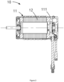
Figure 2 is the sectional view of the electric motor according to the present application. -
Figure 3 is the exploded view of rotor assembly of the electric motor according to the present application. -
Figure 4 is the enlarged view of part A inFigure 3 . -
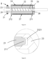
Figure 5 is a cross-sectional view of the rotor assembly of the electric motor according to the present application. -
Figure 6 is the enlarged view of part B inFigure 5 . -
Figure 7 is the schematic diagram of magnetic knitting frame of the electric motor according to the present application. -
Figure 8 is the schematic diagram of rotor assembly of the electric motor according to the present application. -
Figure 9 is the schematic diagram of the rotating shaft of the electric motor according to the present application -
Figure 10 is the exploded view of the front end cover assembly, the stator assembly, and the rear end cover assembly of the electric motor according to the present application. -
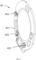
Figure 11 is the schematic diagram of induction components of the electric motor according to the present application. - To facilitate understanding of the application, the application will be described in more detail below in conjunction with the accompanying drawings and embodiments. It should be noted that when an element is referred to as being "fixed to" another element, it may be directly placed on the other element, or one or more elements may be located therebetween. When an element is referred to as being "connected" to another element, such element may be directly attached to another element or one or more elements may be located therebetween. In the description of the present Specification, the terms that indicate the relationship of orientation or position such as "upper," "lower," "inside," "outside," "vertical," and "horizontal" are based on the relationship of orientation or position shown in the accompanying drawings. This is meant to facilitate and simplify the description of the present application and not to imply that the indicated device or element shall have a specific orientation or shall be constructed and operated in a particular orientation. Therefore, it shall not be interpreted as a limitation of the present application. Furthermore, the terms "first" and "second" are used for description only and shall not be construed to indicate or imply relative importance.
- Unless otherwise defined, all technical and scientific terms used in the Specification shall have the same meaning as commonly understood by those skilled in the technical field of this application. The terms used in the Specification of the present application are only for the purpose of specially describing, rather than restricting the application. The term "and/or" in the Specification, includes any and all combinations of one or more of the associated listed items. In addition, the technical features stated in the present application below can be combined with each other, as long as they do not conflict with each other.
- According to the
Figure 1 , theelectric motor 100 includes astator assembly 10, arotor assembly 20, a frontend cover assembly 30, a rearend cover assembly 40, a three-phase power line 50, and adata transmission line 60. Therotor assembly 20 is accommodated in thestator assembly 10. The frontend cover assembly 30 is arranged at the first end of thestator assembly 10. The rearend cover assembly 40 is arranged at the second end of thestator assembly 10. The frontend cover assembly 30 and the rearend cover assembly 40 are both used for supporting therotor assembly 20 so that therotor assembly 20 may rotate relative to thestator assembly 10. One end of the three-phase power line 50 is electrically connected to thestator assembly 10, and the other end of the three-phase power line 50 is electrically connected to an external power supply. Thepower line 50 supplies the three-phase electricity with variable direction to thestator assembly 10, and generates a variable magnetic field to drive the rotation of therotor assembly 20. One end of thedata transmission line 60 is electrically connected to the rearend cover assembly 40, and the other end of thedata transmission line 60 is electrically connected to an external ESC device. The rearend cover assembly 40 is used to sense the magnetic pole information of therotor assembly 20 and to deliver the information to the ESC device through thedata transmission line 60. The ESC device controls any changes to the three-phase electricity of external power source according to the magnetic pole information of therotor assembly 20. - With respect to the above-mentioned
stator assembly 10, please refer to theFigure 2 . Thestator assembly 10 includes ahousing 11 and a winding 12. Thehousing 11 is provided with a receivingcavity 111 whose both ends are communicated with external equipment. The winding 12 is fixedly arranged in the receivingcavity 111, and is electrically connected to the three-phase power line 50. Therotor assembly 20 is sleeved in the winding 12 and rotates relative to the winding 12. - With respect to the above-mentioned
rotor assembly 20, please refer toFigures 3 and5 . Therotor assembly 20 includes amagnetic ring 21, aniron core 22, amagnetic knitting frame 23, several tile-shapedmagnets 24, a rotatingshaft 25, arotor end plate 26 andaramid fibers 27. Theiron core 22 is sleeved on the center of therotating shaft 25, and the two ends of therotating shaft 25 are supported by the frontend cover assembly 30 and the rearend cover assembly 40, respectively. Several tile-shapedmagnets 24 are arranged on the outer surface of theiron core 22, andpositioning slots 241 are formed between two adjacent tile-shapedmagnets 24. Therotor end plate 26 is sleeved on therotating shaft 25 and mounted on the first end of theiron core 22. Themagnetic knitting frame 23 is sleeved on therotating shaft 25, and is mounted on the second end of theiron core 22. Themagnetic ring 21 is arranged on themagnetic knitting frame 23 which is inserted into thepositioning groove 241, so that themagnetic ring 21 correspond to several tile-shapedmagnets 24. Starting from therotor end plate 26, thearamid fiber 27 is wound around the outer surface of the tile-shapedmagnets 24 along the direction of therotor end plate 26 toward themagnetic knitting frame 23. Thearamid fiber 27 stops winding and is secured on themagnetic knitting frame 23. Thearamid fiber 27 around the outer surface of the tile-shapedmagnets 24 can enhance the strength of the tile-shapedmagnets 24 and prevent therotor assembly 20 from explosion due to excessive centrifugal force during the rotation of the tile-shapedmagnets 24. - Please refer to
Figures 3 and6 , themagnetic ring 21 takes an annular structure and is provided with two pairs of opposite magnetic poles, respectively, that is, N- and S-poles. A surface of themagnetic ring 21 is provided with thepositioning strut 211. Thepositioning strut 211 is used for mating and connecting with themagnetic knitting frame 23, so that themagnetic ring 21 can be quickly installed on themagnetic knitting frame 23. - Please refer to
Figure 4 , theiron core 22 takes the form of a hollow cylinder, and is provided with fourfirst installation slots 221 and a firststraight portion 222. Fourfirst installation slots 221 are located on the external surface of theiron core 22. Eachfirst installation slot 221 extends from one end of theiron core 22 to the other end of theiron core 22, and is used for installing a tile-shapedmagnet 24. The firststraight portion 222 is located on the hollow inner wall of theiron core 22, and is used for mating and connecting with the rotatingshaft 25. Thereby theiron core 22 can be quickly positioned and installed on therotating shaft 25. Moreover, the firststraight portion 222 is also able to prevent theiron core 22 from rotating relative torotating shaft 25 when therotor assembly 20 rotates at a high speed. Doing so may affect the correspondence between the tile-shapedmagnet 24 and themagnetic ring 21 and lower the performance of theelectric motor 100. - In this application, there are four tile-shaped
magnets 24, i.e. two N-pole tile-shapedmagnets 24 and two S-pole tile-shapedmagnets 24, respectively. The two N-pole tile-shapedmagnets 24 are oppositely arranged on twofirst installation slots 221. The two S-pole tile-shapedmagnets 24 are oppositely arranged in the remainingfirst installation slots 221. It should be noted that the magnetic poles of the tile-shapedmagnet 24 are located on the outer surface of the tile-shapedmagnet 24, and the magnetic pole of the tile-shapedmagnet 24 corresponds to the magnetic pole of themagnetic ring 21. In other words, the N-pole of the tile-shapedmagnet 24 corresponds to the N pole of themagnetic ring 21, and the S-pole of the tile-shapedmagnet 24 corresponds to the S-pole of themagnetic ring 21. - Please refer to the
Figures 7 and 8 . Themagnetic knitting frame 23 is provided withseveral positioning bosses 231, thesecond installation slot 232, the second wire-embeddingslot 233, thewire outlet 234, and the threadedhole 235.Several positioning bosses 231 are arranged around one end of themagnetic knitting frame 23 at intervals. Thepositioning bosses 231 protrude from one end of themagnetic knitting frame 23 to the direction of another end away from themagnetic knitting frame 23. Thepositioning bosses 231 are used for inserting into thepositioning slots 241, so that themagnetic knitting frame 23 can be quickly and accurately installed on theiron core 22. The second wire-embeddingslot 233 is also arranged at one end of themagnetic knitting frame 23, and is used for winding thefinal section 272 of thearamid fiber 27. Thewire outlet 234 is arranged on the wall of the second wire-embeddingslot 233 and allows thearamid fiber 27 wound in the second wire-embeddingslot 233 to lead out. The threadedhole 235 is arranged in the central portion of themagnetic knitting frame 23, and is used for screwing thefinal section 272 of thearamid fiber 27, so that thefinal section 272 of thearamid fiber 27 is fixed on themagnetic knitting frame 23. Thesecond installation slot 232 is arranged at the other end of themagnetic knitting frame 23. The bottom of thesecond installation slot 232 is provided with apositioning hole 2321. Thesecond installation slot 232 is used for installing themagnetic ring 21, and thepositioning strut 211 of themagnetic ring 21 is inserted into thepositioning hole 2321, so that themagnetic ring 21 can be quickly and accurately installed on themagnetic knitting frame 23. When the positioning struts 211 of themagnetic ring 21 are inserted into thepositioning holes 2321 of thesecond installation slots 232, and thepositioning bosses 231 of themagnetic knitting frame 23 are inserted into thepositioning slots 241 between the tile-shapedmagnets 24, and the magnetic poles of themagnetic ring 21 correspond to the magnetic poles on the outer surface of the tile-shapedmagnets 24. This allows the rapid positioning and installation of themagnetic ring 21 and the tile-shapedmagnets 24. - It can be understood that the number of the threaded
holes 235 may be one, two or more, or optional according to the actual situation. When the number of the threadedholes 235 is two or more, the threadedholes 235 are arranged around the central portion of themagnetic knitting frame 23. - Please refer to
Figure 9 . The rotatingshaft 25 includes thefirst section 251, thesecond section 252 and thethird section 253. Thefirst section 251 and thethird section 253 are respectively arranged at both ends of thesecond section 252. Thefirst section 251, thesecond section 252, and thethird section 253 are located on the same straight line. Thefirst section 251 is provided with thefirst rib 2511. Thefirst rib 2511 is used to accommodate adhesive. Therotor end plate 26 passing through thefirst section 251 is installed at thefirst rib 2511. The adhesive accommodated in thefirst rib 2511 is used to fix therotor end plate 26 to thefirst section 251. Thesecond section 252 is provided with a secondstraight portion 2521 and an adhesive slot 2522. The secondstraight portion 2521 extends from one end of thesecond section 252 to the other end of thesecond section 252. The secondstraight portion 2521 is used for mating and connecting with the firststraight portion 222, so that after theiron core 22 is sleeved on thesecond section 252, theiron core 22 cannot rotate relative to thesecond section 252, but can only rotate synchronously with thesecond section 252. The adhesive slot 2522 is arranged spirally around the surface of thesecond section 252. The adhesive slot 2522 is used for accommodating the adhesive, in order to fix theiron core 22 sleeved in thesecond section 252 onto thesecond section 252, and to prevent the direction of theiron core 22 extending along the second section 252 (ie the axial direction of the second section 252) away from thesecond section 252. It can be understood that, in the present application, the spiral-shaped adhesive slot 2522 takes a connective structure from beginning to end. A plurality of annular adhesive slots 2522 are arranged on the surface of thesecond section 252 and are not connected to each other. Thethird section 253 is provided with asecond rib 2531 which is used to accommodate the adhesive. Themagnetic knitting frame 23 passing through thethird section 253 is installed at thesecond rib 2531. The adhesive is used to fix themagnetic knitting frame 23 to thethird section 253. - Please continue to refer to
Figures 3 and5 . Therotor end plate 26 is provided with the first wire-embeddingslot 261 which is arranged around therotor end plate 26, and is used to accommodate theinitial section 271 of thearamid fiber 27. This leads to the same diameters of thearamid fibers 27 wound around the surface of therotor end plate 26, of the tile-shapedmagnet 24, and of themagnetic knitting frame 23. In other words, the external diameter of theinitial section 271 of thearamid fiber 27 is not greater than the external diameter of other portion of thearamid fiber 27, leading to a more reliable structure of theelectric motor 100. Meanwhile, the consistency of external diameters of thearamid fiber 27 wound around therotor assembly 20 ensures the more stable and secure operation of therotor assembly 20 during rotation. - Please continue to refer to
Figures 3 and5 . Therotor assembly 20 also includes the first dynamic balancingmember 28 and/or the second dynamic balancingmember 29. At the time of debugging and assembling theelectric motor 100, the first dynamic balancingmember 28 may be provided at therotor end plate 26, the second dynamic balancingmember 29 is provided on themagnetic knitting frame 23, or the first dynamic balancingmember 28 is only provided on therotor end plate 26, or the second dynamic balancingmember 29 is only provided on themagnetic knitting frame 23, according to actual situation. This allows therotor assembly 20 to always maintain stable rotation, reduce the vibration amplitude of therotor assembly 20 during rotation, and improve the performance of theelectric motor 100. Both the first dynamic balancingmember 28 and the second dynamic balancingmember 29 are made of cement plaster which can be directly applied on therotor end plate 26 and/or themagnetic knitting frame 23. - For the aforesaid front
end cover assembly 30, please refer toFigure 10 . The frontend cover assembly 30 includes afront end fastener 31, afront cover plate 32 and afirst bearing 33. Thefirst bearing 33 is arranged on thefront cover plate 32. Thefirst bearing 33 allows the passage of thefirst section 251 of therotating shaft 25, and the rotation of thefirst section 251. Thefront cover plate 32 is arranged on the first end of thehousing 11 for covering and accommodating the first end of the receivingcavity 111. Thefront end fastener 31 is arranged around thefront cover plate 32, and is used to fix thefront cover plate 32 to the first end of thehousing 11. - With respect to the foregoing rear
end cover assembly 40, please refer toFigures 10 and11 . The rearend cover assembly 40 includes arear end fastener 41,induction components 42, arear cover plate 43, and asecond bearing 44. Thesecond bearing 44 and theinduction components 42 are arranged on therear cover 43. Thesecond bearing 44 allows the passage of thethird section 253 of therotating shaft 25 and the rotation of thethird section 253. Theinduction components 42 include a Printed Circuit Board Assembly (PCBA) board andHall element 422. TheHall element 422 is arranged on thePCBA board 421 which is electrically connected to thedata transmission line 60. TheHall element 422 is used to sense the magnetic pole information of themagnetic ring 21, thereby sensing the magnetic pole information of the tile-shapedmagnet 24 which is transmitted to the external ESC device through thedata transmission line 60. The external ESC device is used to adjust the power supply parameters delivered to the winding 12 through the three-phase power line 50 according to the magnetic pole information of the tile-shapedmagnet 24, so that the winding 12 may generate a variable magnetic field to drive the rotation of therotor assembly 20. Therear cover plate 43 is arranged on the second end of thehousing 11 to cover and accommodate the second end of the receivingcavity 111. Therear end fastener 41 is arranged around therear cover plate 43 to fix therear cover plate 43 on the second end of thehousing 11. - Please continue to refer to
Figure 1 , theelectric motor 100 also includes a preloadingstructure 70. The preloadingstructure 70 is sleeved on the first end of therotating shaft 25, and is located between therotor end plate 26 and thefirst bearing 33. Meanwhile, the preloadingstructure 70 serves as a cushion for the axial movement of therotor assembly 20. This aims to reduce the gap between therotor assembly 20 and the frontend cover assembly 30, improve the stability of therotor assembly 20 during rotation, and lower the noise generated during the operation of theelectric motor 100. The preloadingstructure 70 includes a first gasket 71 and an elastic gasket 72. The elastic gasket 72 is adjacent to therotor assembly 20. The first gasket 71 is adjacent to thefirst bearing 33 and is used for supporting the elastic gasket 72. The elastic gasket 72 transfers the axial elastic force to therotor assembly 20. - The present application has the following beneficial effects: the
electric motor 100 includes astator assembly 10, arotor assembly 20, a frontend cover assembly 30, a rearend cover assembly 40, a three-phase power line 50, and adata transmission line 60. Therotor assembly 20 is sleeved in thestator assembly 10. The frontend cover assembly 30 and the rearend cover assembly 40 are disposed on both ends of thestator assembly 10, respectively. The two ends of the three-phase power line 50 are electrically connected to thestator assembly 10 and the external power supply, respectively. The two ends of thedata transmission line 60 are electrically connected to the rearend cover assembly 40 and the external ESC device, respectively. Therotor assembly 20 includes amagnetic ring 21, amagnetic knitting frame 23, aniron core 22, several tile-shapedmagnets 24, a rotatingshaft 25 and arotor end plate 26. Theiron core 22 is sleeved on therotating shaft 25, and is provided with afirst installation slot 221. The tile-shapedmagnet 24 is arranged in thefirst installation slot 221. Thepositioning slot 241 is arranged between two adjacent tile-shapedmagnets 24. Therotor end plate 26 is sleeved on therotating shaft 25, and is located on the first end of theiron core 22. Themagnetic knitting frame 23 is sleeved on therotating shaft 25, and is located on the second end of theiron core 22. One end of themagnetic knitting frame 23 is provided with apositioning boss 231 which is inserted into thepositioning slot 241. Themagnetic ring 21 is arranged on the other end of themagnetic knitting frame 23, so that the magnetic poles of themagnetic ring 21 corresponds to those of the tile-shapedmagnets 24. The rearend cover assembly 40 includesinduction components 42 which are used to sense the magnetic pole information of themagnetic ring 21 and the tile-shapedmagnet 24 and to send the information to the external ESC device. The external ESC device may adjust the power supply of the external power source to thestator assembly 10 according to the magnetic pole information. Apositioning slot 241 is arranged between adjacent tile-shapedmagnets 24. Themagnetic knitting frame 23 is provided with apositioning boss 231 that is inserted into the structure of thepositioning slot 241. Theelectric motor 100 allows the accurate positioning and assembling of therotor assembly 20, so that the magnetic poles of themagnetic ring 21 corresponds to the magnetic poles of the tile-shapedmagnet 24. This improves the positioning accuracy of therotor assembly 20 of the electric motor, enhances the accuracy of theinduction components 42 used for sensing the tile-shapedmagnet 24, leading to the better performance of theelectric motor 100. - The application also provides an electric toy that includes the aforesaid
electric motor 100. Theelectric motor 100 is used to power the electric toy. Electric toys include drones, remote control cars, electric fans, and other devices that require theelectric motor 100 as a power source. For the structure and function of theelectric motor 100, reference may be made to the aforesaidelectric motor 100 without further elaboration here.
Claims (9)
- An electric motor (100) is characterized by comprising:a stator assembly (10), comprising a housing (11) and a winding (12); wherein the housing (11) is provided with a receiving cavity (111), and the winding (12) is accommodated in the receiving cavity (111);a rotor assembly (20), sleeved in the winding (12); wherein the rotor assembly comprises a magnetic ring (21), a magnetic knitting frame (23), an iron core (22), several tile-shaped magnets (24), a rotating shaft (25), aramid fiber (27), and a rotor end plate (26);the iron core (22) is sleeved in the rotating shaft (25) and is provided with a first installation slot (221),tile-shaped magnet (24) is arranged in the first installation slot (221) and a positioning slot (241) is arranged between two adjacent tile-shaped magnets (24);the aramid fiber (27) is wound around the outer surface of the tile-shaped magnet (24);the rotor end plate (26) is sleeved on the rotating shaft (25), and is arranged on first end of the iron core (22);the magnetic knitting frame (23) is sleeved on the rotating shaft (25), and is located on second end of the iron core (22); one end of the magnetic knitting frame (23) is provided with a positioning boss (231) which is inserted into the positioning slot (241);the magnetic ring (21) is arranged on the other end of the magnetic knitting frame (23);the rotor end plate (26) is provided with a first wire-embedding slot (261); the magnetic knitting frame (23) is provided with a second wire-embedding slot (233), a wire outlet (234) and a threaded hole (235);the wire outlet (234) is arranged on the wall of the second wire-embedding slot (233); the first wire-embedding slot (261) is used for accommodating initial sections of the aramid fiber (27), and the second wire-embedding slot is used for accommodating final sections of the aramid fiber (27);the final section of the aramid fiber (27) goes through the wire outlet (234) and is fixed to the threaded hole (235) after being led out;the number of the threaded hole (235) is at least one, and the threaded hole (235) is arranged at the central portion of the magnetic knitting frame (23);a front end cover assembly (30), comprising a front end fastener (31) and a front cover plate (32); wherein the front cover plate (32) is arranged on the first end of the housing (11), and the front end fastener (31) is used for fixing the front cover plate (32) to the housing (11);a rear end cover assembly (40), comprising a rear end fastener (41), induction components (42) and a rear cover plate (43); wherein the induction components (42) are arranged on the rear cover plate (43), and are used for sensing the magnetic ring (21), and the rear end fastener (41) is used for fixing the rear cover (43) to the second end of the housing (11);a three-phase power line (50), electrically connected to the winding (12);a data transmission line (60), one end of which is electrically connected to induction components (42) and the other end of which is electrically connected to an external electronic speed control (ESC) device.
- The electric motor stated in Claim 1 is characterized in that,the iron core (22) is provided with a first straight portion (222);the rotating shaft (25) comprises a first section (251), a second section (252) and a third section (253);wherein the first section (251) and the third section (253) are respectively located at different ends of the second section (252); the second section (252) is provided with a second straight portion (2521); the first straight portion (222) is connected to the second straight portion (2521) so as to locate the iron core (22) on the second section of the rotating shaft (25); the rotor end plate (26) is sleeved on the first section (251), and the magnetic knitting frame (23) is sleeved on the third section (253).
- The electric motor stated in Claim 2 is characterized in that,
the second section (252) is provided with an adhesive slot (2522), the end of the first section (251) adjacent to the second section (252) is provided with a first rib (2511) and the end of the third section (253) adjacent to the second section (252) is provided with a second rib (2531), wherein the adhesive slot (2522), the first rib (2511) and second rib (2531) are all used to store adhesive. - The electric motor stated in Claim 2 is characterized in that,
the other end of the magnetic knitting frame (23) is provided with a second installation slot (232), and the bottom of the second installation slot (232) is provided with a positioning hole (2321); the magnetic ring (21) is arranged at the second installation slot (232), and is provided with a positioning strut (211). The positioning strut (211) is inserted into the positioning hole (2321); wherein the magnetic poles of the magnetic ring (21) correspond to the magnetic poles on the outer surface of the tile-shaped magnet (24). - The electric motor stated in Claim 1 is characterized in that,
the rotor assembly (20) further comprises a first dynamic balancing member (28) and a second dynamic balancing member (29); wherein the first dynamic balancing member (28) is arranged on the rotor end plate (26), and the second dynamic balancing member (29) is arranged on the magnetic knitting frame (23). - The electric motor stated in Claim 1 is characterized in that,the front end cover assembly (30) further comprises a first bearing (33) which is arranged on the front cover plate (32), and is used for supporting the first section (251) of the rotating shaft (25);the rear end cover assembly (40) further comprises a second bearing (44) which is arranged on the rear cover plate (43), and is used for supporting the third section (253) of the rotating shaft (25).
- The electric motor stated in Claim 6 is characterized in that,
the electric motor (100) further comprises a preloading structure (70) disposed between the rotor assembly (20) and the front end cover assembly (30), wherein the preloading structure (70) serves as a cushion for the axial movement of the rotor assembly (20). - The electric motor stated in Claim 7 is characterized in that,
the preloading structure (70) comprises a first gasket (71) and an elastic gasket (72), which are both sleeved on the rotating shaft (25); wherein the first gasket (71) abuts the first bearing (33), and the elastic gasket (72) abuts the rotor end plate (26). - An electric toy is characterized by comprising the electric motor (100) according to any one of Claims 1-8; wherein the electric motor (100) is used to power the electric toy.
Applications Claiming Priority (1)
| Application Number | Priority Date | Filing Date | Title |
|---|---|---|---|
| CN202210443911.6A CN114552821B (en) | 2022-04-26 | 2022-04-26 | Motor and electric toy |
Publications (3)
| Publication Number | Publication Date |
|---|---|
| EP4270735A1 EP4270735A1 (en) | 2023-11-01 |
| EP4270735C0 EP4270735C0 (en) | 2025-04-23 |
| EP4270735B1 true EP4270735B1 (en) | 2025-04-23 |
Family
ID=81667704
Family Applications (1)
| Application Number | Title | Priority Date | Filing Date |
|---|---|---|---|
| EP22213773.9A Active EP4270735B1 (en) | 2022-04-26 | 2022-12-15 | An electric motor and an electric toy |
Country Status (3)
| Country | Link |
|---|---|
| US (1) | US11794123B1 (en) |
| EP (1) | EP4270735B1 (en) |
| CN (1) | CN114552821B (en) |
Families Citing this family (3)
| Publication number | Priority date | Publication date | Assignee | Title |
|---|---|---|---|---|
| US12494687B2 (en) * | 2022-10-31 | 2025-12-09 | GM Global Technology Operations LLC | Rotor assembly with a composite sleeve that is optimized for press-fit installation |
| IT202300010020A1 (en) * | 2023-05-18 | 2024-11-18 | Ferrari Spa | ROTOR FOR A ROTATING ELECTRIC MACHINE |
| CN223404405U (en) | 2024-11-15 | 2025-10-03 | 林少青 | Multi-stage synchronous drive mechanism and electric toy |
Family Cites Families (11)
| Publication number | Priority date | Publication date | Assignee | Title |
|---|---|---|---|---|
| US4930201A (en) * | 1985-08-14 | 1990-06-05 | Kollmorgen Corporation | Method for manufacturing a composite sleeve for an electric motor |
| DE102006015037A1 (en) * | 2006-03-31 | 2007-10-11 | Siemens Ag | Rotor of a permanent magnet synchronous machine |
| US20100019598A1 (en) * | 2008-07-28 | 2010-01-28 | Direct Drive Systems, Inc. | Rotor for an electric machine |
| CN102480204B (en) * | 2010-11-26 | 2015-04-29 | 中山大洋电机股份有限公司 | Rotor assembly |
| TWI509952B (en) * | 2014-05-15 | 2015-11-21 | Sunonwealth Electr Mach Ind Co | Motor of ceiling fan |
| CN106972721A (en) * | 2017-04-21 | 2017-07-21 | 郑州飞机装备有限责任公司 | High power density electric vehicle permagnetic synchronous motor |
| CN207283285U (en) * | 2017-10-31 | 2018-04-27 | 浙江联宜电机有限公司 | Brushless electric machine reaction magnetic ring assembling structure |
| CN208924041U (en) * | 2018-09-28 | 2019-05-31 | 浙江万冠电机有限公司 | A kind of brshless DC motor |
| CN113675982A (en) * | 2020-05-15 | 2021-11-19 | 广东威灵电机制造有限公司 | Rotating electrical machine and fan |
| CN111641279B (en) * | 2020-07-07 | 2025-07-25 | 汇润电气有限公司 | Brushless DC motor |
| CN213906400U (en) * | 2020-11-11 | 2021-08-06 | 深圳拓邦股份有限公司 | Outer rotor assembly and outer rotor motor |
-
2022
- 2022-04-26 CN CN202210443911.6A patent/CN114552821B/en active Active
- 2022-11-08 US US17/983,096 patent/US11794123B1/en active Active
- 2022-12-15 EP EP22213773.9A patent/EP4270735B1/en active Active
Also Published As
| Publication number | Publication date |
|---|---|
| EP4270735C0 (en) | 2025-04-23 |
| EP4270735A1 (en) | 2023-11-01 |
| US11794123B1 (en) | 2023-10-24 |
| US20230338867A1 (en) | 2023-10-26 |
| CN114552821B (en) | 2022-07-19 |
| CN114552821A (en) | 2022-05-27 |
Similar Documents
| Publication | Publication Date | Title |
|---|---|---|
| EP4270735A1 (en) | An electric motor and an electric toy | |
| US9124161B2 (en) | Double-stator/double-rotor type motor and direct drive apparatus for washer using same | |
| US20110291514A1 (en) | Resilient rotor assembly for interior permanent magnet motor | |
| US20130052061A1 (en) | Brushless motor | |
| CN106558965A (en) | Electric machine and drive mechanism | |
| US11121663B2 (en) | 2-phase outer ring switched reluctance motor for low-speed and high-flow rate fan | |
| EP2712069A2 (en) | Rotating electrical machine | |
| JP2019075982A (en) | Electric machine | |
| US7116024B2 (en) | Electric motor and method for its production | |
| CN120033941B (en) | Be applied to frameless moment motor of robot | |
| KR101216588B1 (en) | Out rotor type fan motor | |
| KR100688158B1 (en) | Electric motor with two rotors | |
| JPH1118361A (en) | Controller integrated motor | |
| KR102099897B1 (en) | Magnet generator | |
| CN210350881U (en) | Outer rotor hybrid stepping motor | |
| CN210246537U (en) | Brushless fan | |
| KR20140141858A (en) | Sensing module | |
| KR20210037167A (en) | Motor | |
| CN220067184U (en) | Brushless motor | |
| CN207442635U (en) | A kind of starter-generator | |
| KR20070009170A (en) | motor | |
| JP2021122171A (en) | Stepping motor | |
| CN221652412U (en) | Integrated drive and control motor | |
| CN215186209U (en) | Improved motor support and motor | |
| CN210608881U (en) | Brushless motor |
Legal Events
| Date | Code | Title | Description |
|---|---|---|---|
| PUAI | Public reference made under article 153(3) epc to a published international application that has entered the european phase |
Free format text: ORIGINAL CODE: 0009012 |
|
| STAA | Information on the status of an ep patent application or granted ep patent |
Free format text: STATUS: REQUEST FOR EXAMINATION WAS MADE |
|
| 17P | Request for examination filed |
Effective date: 20221215 |
|
| AK | Designated contracting states |
Kind code of ref document: A1 Designated state(s): AL AT BE BG CH CY CZ DE DK EE ES FI FR GB GR HR HU IE IS IT LI LT LU LV MC ME MK MT NL NO PL PT RO RS SE SI SK SM TR |
|
| GRAP | Despatch of communication of intention to grant a patent |
Free format text: ORIGINAL CODE: EPIDOSNIGR1 |
|
| STAA | Information on the status of an ep patent application or granted ep patent |
Free format text: STATUS: GRANT OF PATENT IS INTENDED |
|
| INTG | Intention to grant announced |
Effective date: 20240902 |
|
| GRAJ | Information related to disapproval of communication of intention to grant by the applicant or resumption of examination proceedings by the epo deleted |
Free format text: ORIGINAL CODE: EPIDOSDIGR1 |
|
| STAA | Information on the status of an ep patent application or granted ep patent |
Free format text: STATUS: REQUEST FOR EXAMINATION WAS MADE |
|
| INTC | Intention to grant announced (deleted) | ||
| GRAP | Despatch of communication of intention to grant a patent |
Free format text: ORIGINAL CODE: EPIDOSNIGR1 |
|
| STAA | Information on the status of an ep patent application or granted ep patent |
Free format text: STATUS: GRANT OF PATENT IS INTENDED |
|
| GRAS | Grant fee paid |
Free format text: ORIGINAL CODE: EPIDOSNIGR3 |
|
| GRAA | (expected) grant |
Free format text: ORIGINAL CODE: 0009210 |
|
| STAA | Information on the status of an ep patent application or granted ep patent |
Free format text: STATUS: THE PATENT HAS BEEN GRANTED |
|
| INTG | Intention to grant announced |
Effective date: 20250219 |
|
| AK | Designated contracting states |
Kind code of ref document: B1 Designated state(s): AL AT BE BG CH CY CZ DE DK EE ES FI FR GB GR HR HU IE IS IT LI LT LU LV MC ME MK MT NL NO PL PT RO RS SE SI SK SM TR |
|
| REG | Reference to a national code |
Ref country code: GB Ref legal event code: FG4D |
|
| REG | Reference to a national code |
Ref country code: CH Ref legal event code: EP |
|
| REG | Reference to a national code |
Ref country code: DE Ref legal event code: R096 Ref document number: 602022013507 Country of ref document: DE |
|
| REG | Reference to a national code |
Ref country code: IE Ref legal event code: FG4D |
|
| U01 | Request for unitary effect filed |
Effective date: 20250513 |
|
| U07 | Unitary effect registered |
Designated state(s): AT BE BG DE DK EE FI FR IT LT LU LV MT NL PT RO SE SI Effective date: 20250519 |
|
| PG25 | Lapsed in a contracting state [announced via postgrant information from national office to epo] |
Ref country code: ES Free format text: LAPSE BECAUSE OF FAILURE TO SUBMIT A TRANSLATION OF THE DESCRIPTION OR TO PAY THE FEE WITHIN THE PRESCRIBED TIME-LIMIT Effective date: 20250423 |
|
| PG25 | Lapsed in a contracting state [announced via postgrant information from national office to epo] |
Ref country code: GR Free format text: LAPSE BECAUSE OF FAILURE TO SUBMIT A TRANSLATION OF THE DESCRIPTION OR TO PAY THE FEE WITHIN THE PRESCRIBED TIME-LIMIT Effective date: 20250724 Ref country code: NO Free format text: LAPSE BECAUSE OF FAILURE TO SUBMIT A TRANSLATION OF THE DESCRIPTION OR TO PAY THE FEE WITHIN THE PRESCRIBED TIME-LIMIT Effective date: 20250723 |
|
| PG25 | Lapsed in a contracting state [announced via postgrant information from national office to epo] |
Ref country code: PL Free format text: LAPSE BECAUSE OF FAILURE TO SUBMIT A TRANSLATION OF THE DESCRIPTION OR TO PAY THE FEE WITHIN THE PRESCRIBED TIME-LIMIT Effective date: 20250423 |
|
| PG25 | Lapsed in a contracting state [announced via postgrant information from national office to epo] |
Ref country code: HR Free format text: LAPSE BECAUSE OF FAILURE TO SUBMIT A TRANSLATION OF THE DESCRIPTION OR TO PAY THE FEE WITHIN THE PRESCRIBED TIME-LIMIT Effective date: 20250423 |
|
| PG25 | Lapsed in a contracting state [announced via postgrant information from national office to epo] |
Ref country code: RS Free format text: LAPSE BECAUSE OF FAILURE TO SUBMIT A TRANSLATION OF THE DESCRIPTION OR TO PAY THE FEE WITHIN THE PRESCRIBED TIME-LIMIT Effective date: 20250723 |
|
| PG25 | Lapsed in a contracting state [announced via postgrant information from national office to epo] |
Ref country code: IS Free format text: LAPSE BECAUSE OF FAILURE TO SUBMIT A TRANSLATION OF THE DESCRIPTION OR TO PAY THE FEE WITHIN THE PRESCRIBED TIME-LIMIT Effective date: 20250823 |
|
| U1N | Appointed representative for the unitary patent procedure changed after the registration of the unitary effect |
Representative=s name: SANTARELLI; FR |
|
| U20 | Renewal fee for the european patent with unitary effect paid |
Year of fee payment: 4 Effective date: 20251127 |
|
| PG25 | Lapsed in a contracting state [announced via postgrant information from national office to epo] |
Ref country code: SM Free format text: LAPSE BECAUSE OF FAILURE TO SUBMIT A TRANSLATION OF THE DESCRIPTION OR TO PAY THE FEE WITHIN THE PRESCRIBED TIME-LIMIT Effective date: 20250423 |
|
| PG25 | Lapsed in a contracting state [announced via postgrant information from national office to epo] |
Ref country code: CZ Free format text: LAPSE BECAUSE OF FAILURE TO SUBMIT A TRANSLATION OF THE DESCRIPTION OR TO PAY THE FEE WITHIN THE PRESCRIBED TIME-LIMIT Effective date: 20250423 |
|
| PG25 | Lapsed in a contracting state [announced via postgrant information from national office to epo] |
Ref country code: SK Free format text: LAPSE BECAUSE OF FAILURE TO SUBMIT A TRANSLATION OF THE DESCRIPTION OR TO PAY THE FEE WITHIN THE PRESCRIBED TIME-LIMIT Effective date: 20250423 |
|
| PLBE | No opposition filed within time limit |
Free format text: ORIGINAL CODE: 0009261 |
|
| STAA | Information on the status of an ep patent application or granted ep patent |
Free format text: STATUS: NO OPPOSITION FILED WITHIN TIME LIMIT |
|
| REG | Reference to a national code |
Ref country code: CH Ref legal event code: L10 Free format text: ST27 STATUS EVENT CODE: U-0-0-L10-L00 (AS PROVIDED BY THE NATIONAL OFFICE) Effective date: 20260304 |
|
| 26N | No opposition filed |
Effective date: 20260126 |