EP4270619A1 - Battery - Google Patents
Battery Download PDFInfo
- Publication number
- EP4270619A1 EP4270619A1 EP21915085.1A EP21915085A EP4270619A1 EP 4270619 A1 EP4270619 A1 EP 4270619A1 EP 21915085 A EP21915085 A EP 21915085A EP 4270619 A1 EP4270619 A1 EP 4270619A1
- Authority
- EP
- European Patent Office
- Prior art keywords
- battery
- axis direction
- slot
- tray
- mobile
- Prior art date
- Legal status (The legal status is an assumption and is not a legal conclusion. Google has not performed a legal analysis and makes no representation as to the accuracy of the status listed.)
- Pending
Links
Images
























Classifications
-
- H—ELECTRICITY
- H01—ELECTRIC ELEMENTS
- H01M—PROCESSES OR MEANS, e.g. BATTERIES, FOR THE DIRECT CONVERSION OF CHEMICAL ENERGY INTO ELECTRICAL ENERGY
- H01M50/00—Constructional details or processes of manufacture of the non-active parts of electrochemical cells other than fuel cells, e.g. hybrid cells
- H01M50/20—Mountings; Secondary casings or frames; Racks, modules or packs; Suspension devices; Shock absorbers; Transport or carrying devices; Holders
- H01M50/244—Secondary casings; Racks; Suspension devices; Carrying devices; Holders characterised by their mounting method
-
- H—ELECTRICITY
- H01—ELECTRIC ELEMENTS
- H01M—PROCESSES OR MEANS, e.g. BATTERIES, FOR THE DIRECT CONVERSION OF CHEMICAL ENERGY INTO ELECTRICAL ENERGY
- H01M50/00—Constructional details or processes of manufacture of the non-active parts of electrochemical cells other than fuel cells, e.g. hybrid cells
- H01M50/20—Mountings; Secondary casings or frames; Racks, modules or packs; Suspension devices; Shock absorbers; Transport or carrying devices; Holders
- H01M50/204—Racks, modules or packs for multiple batteries or multiple cells
-
- H—ELECTRICITY
- H01—ELECTRIC ELEMENTS
- H01M—PROCESSES OR MEANS, e.g. BATTERIES, FOR THE DIRECT CONVERSION OF CHEMICAL ENERGY INTO ELECTRICAL ENERGY
- H01M50/00—Constructional details or processes of manufacture of the non-active parts of electrochemical cells other than fuel cells, e.g. hybrid cells
- H01M50/20—Mountings; Secondary casings or frames; Racks, modules or packs; Suspension devices; Shock absorbers; Transport or carrying devices; Holders
- H01M50/204—Racks, modules or packs for multiple batteries or multiple cells
- H01M50/207—Racks, modules or packs for multiple batteries or multiple cells characterised by their shape
- H01M50/213—Racks, modules or packs for multiple batteries or multiple cells characterised by their shape adapted for cells having curved cross-section, e.g. round or elliptic
-
- H—ELECTRICITY
- H01—ELECTRIC ELEMENTS
- H01M—PROCESSES OR MEANS, e.g. BATTERIES, FOR THE DIRECT CONVERSION OF CHEMICAL ENERGY INTO ELECTRICAL ENERGY
- H01M50/00—Constructional details or processes of manufacture of the non-active parts of electrochemical cells other than fuel cells, e.g. hybrid cells
- H01M50/20—Mountings; Secondary casings or frames; Racks, modules or packs; Suspension devices; Shock absorbers; Transport or carrying devices; Holders
- H01M50/256—Carrying devices, e.g. belts
-
- H—ELECTRICITY
- H01—ELECTRIC ELEMENTS
- H01M—PROCESSES OR MEANS, e.g. BATTERIES, FOR THE DIRECT CONVERSION OF CHEMICAL ENERGY INTO ELECTRICAL ENERGY
- H01M50/00—Constructional details or processes of manufacture of the non-active parts of electrochemical cells other than fuel cells, e.g. hybrid cells
- H01M50/20—Mountings; Secondary casings or frames; Racks, modules or packs; Suspension devices; Shock absorbers; Transport or carrying devices; Holders
- H01M50/296—Mountings; Secondary casings or frames; Racks, modules or packs; Suspension devices; Shock absorbers; Transport or carrying devices; Holders characterised by terminals of battery packs
-
- H—ELECTRICITY
- H02—GENERATION; CONVERSION OR DISTRIBUTION OF ELECTRIC POWER
- H02J—ELECTRIC POWER NETWORKS; CIRCUIT ARRANGEMENTS OR SYSTEMS FOR SUPPLYING OR DISTRIBUTING ELECTRIC POWER; SYSTEMS FOR STORING ELECTRIC ENERGY
- H02J7/00—Circuit arrangements for charging or discharging batteries or for supplying loads from batteries
- H02J7/70—Circuit arrangements for charging or discharging batteries or for supplying loads from batteries characterised by the mechanical construction
- H02J7/751—Circuit arrangements for charging or discharging batteries or for supplying loads from batteries characterised by the mechanical construction concerning the insertion or the connection of the batteries
-
- H—ELECTRICITY
- H02—GENERATION; CONVERSION OR DISTRIBUTION OF ELECTRIC POWER
- H02J—ELECTRIC POWER NETWORKS; CIRCUIT ARRANGEMENTS OR SYSTEMS FOR SUPPLYING OR DISTRIBUTING ELECTRIC POWER; SYSTEMS FOR STORING ELECTRIC ENERGY
- H02J7/00—Circuit arrangements for charging or discharging batteries or for supplying loads from batteries
- H02J7/50—Circuit arrangements for charging or discharging batteries or for supplying loads from batteries acting upon multiple batteries simultaneously or sequentially
-
- H—ELECTRICITY
- H02—GENERATION; CONVERSION OR DISTRIBUTION OF ELECTRIC POWER
- H02J—ELECTRIC POWER NETWORKS; CIRCUIT ARRANGEMENTS OR SYSTEMS FOR SUPPLYING OR DISTRIBUTING ELECTRIC POWER; SYSTEMS FOR STORING ELECTRIC ENERGY
- H02J7/00—Circuit arrangements for charging or discharging batteries or for supplying loads from batteries
- H02J7/80—Circuit arrangements for charging or discharging batteries or for supplying loads from batteries including monitoring or indicating arrangements
- H02J7/82—Control of state of charge [SOC]
-
- Y—GENERAL TAGGING OF NEW TECHNOLOGICAL DEVELOPMENTS; GENERAL TAGGING OF CROSS-SECTIONAL TECHNOLOGIES SPANNING OVER SEVERAL SECTIONS OF THE IPC; TECHNICAL SUBJECTS COVERED BY FORMER USPC CROSS-REFERENCE ART COLLECTIONS [XRACs] AND DIGESTS
- Y02—TECHNOLOGIES OR APPLICATIONS FOR MITIGATION OR ADAPTATION AGAINST CLIMATE CHANGE
- Y02E—REDUCTION OF GREENHOUSE GAS [GHG] EMISSIONS, RELATED TO ENERGY GENERATION, TRANSMISSION OR DISTRIBUTION
- Y02E60/00—Enabling technologies; Technologies with a potential or indirect contribution to GHG emissions mitigation
- Y02E60/10—Energy storage using batteries
Definitions
- the present invention relates to a battery including a grip member that is gripped by a user.
- a battery unit is disclosed.
- the outer shape of the battery unit is formed substantially in the shape of a rectangular parallelepiped.
- the battery unit includes a grip member on an upper surface thereof.
- the battery unit is accommodated in an accommodating slot of an electric vehicle.
- the battery unit is used as an electrical power source for the electric vehicle.
- the battery unit is accommodated in an accommodating slot of a charging station. Charging of the battery unit is carried out by the charging station.
- the battery unit disclosed in WO 2018/235204 A1 is provided with connection terminals on a bottom surface of a main body portion. In a state in which the battery unit is accommodated in the accommodating slot, the connection terminals are connected to terminals that are provided in the accommodating slot. The connection terminals of the battery unit are provided at a position that is shifted from the center of the bottom surface. Therefore, it is necessary that the battery unit be accommodated in a prescribed posture in the accommodating slot.
- the battery unit disclosed in WO 2018/235204 A1 has a problem in that the battery unit is accommodated in the accommodating slot in a posture that differs from such a prescribed posture.
- the present invention has the object of solving the aforementioned problem.
- An aspect of the present invention is characterized by a battery having a substantially rectangular parallelepiped outer shape, the battery comprising a first surface and a second surface which are side surfaces of both ends thereof in a longitudinal direction, a third surface which is a side surface substantially perpendicular to the first surface and the second surface, a fourth surface which is a side surface substantially perpendicular to the first surface and the second surface, and which is on an opposite side from the third surface, a fifth surface which is a side surface substantially perpendicular to the first surface, the second surface, the third surface, and the fourth surface, a sixth surface which is a side surface substantially perpendicular to the first surface and the second surface, and which is on an opposite side from the fifth surface, and a grip member provided on the first surface, wherein the grip member includes a first portion configured to extend in a direction from the fifth surface toward the sixth surface, at a position between the third surface and the fourth surface and closer to the third surface than the fourth surface, and a second portion configured to extend in a direction from
- the battery unit can be accommodated in a prescribed posture in the accommodating slot.
- FIG. 1 is an external schematic diagram of a battery exchange device 10.
- the battery exchange device 10 accommodates a mobile battery 12 in the interior thereof.
- the battery exchange device 10 carries out charging of the mobile battery 12.
- a user deposits the mobile battery 12 having a low remaining power capacity (SOC: state of charge) in the battery exchange device 10.
- SOC state of charge
- the user receives another fully charged mobile battery 12 from the battery exchange device 10.
- the battery exchange device 10 corresponds to an external device of the present invention.
- the mobile battery 12 corresponds to a battery of the present invention.
- the battery exchange device 10 includes eight slots 14.
- the battery exchange device 10 includes a single operation panel 16.
- Mobile batteries 12 are accommodated in the slots 14.
- An indicator 20 is provided above the slot 14.
- the indicator 20 displays the state of charge of the mobile battery 12 that is accommodated in the slot 14 by illumination of colors, flashing, or the like.
- the operation panel 16 is a device that is operated by the user. By operating the operation panel 16, for example, the user carries out payment of a fee or the like.
- the slot 14 opens on a front surface 10a of the battery exchange device 10.
- the front surface 10a of the battery exchange device 10 is inclined with respect to the vertical direction (the direction of gravity). In a state with the user standing facing the front surface 10a, an upper part of the front surface 10a is positioned more rearward than a lower part thereof.
- the user is capable of leaning forward at a time when the user inserts the mobile battery 12 into the slot 14. Therefore, it becomes easier to insert the mobile battery 12 into the slot 14.
- FIG. 2 is a cross-sectional view of the battery exchange device 10.
- the battery exchange device 10 includes a control device 22 located above the slots 14.
- the control device 22 controls charging or the like of the mobile batteries 12.
- the battery exchange device 10 includes a utility space 24 located below the slots 14.
- a cooling device or the like may be installed in the utility space 24. The cooling device serves to cool the interior of the battery exchange device 10.
- FIG. 3 and FIG. 4 are perspective views of the slot 14.
- FIG. 5 is a side view of the slot 14.
- the present embodiment will be described based on an X-axis, a Y-axis, and a Z-axis, which are defined in the following manner.
- the direction in which the mobile battery 12 is inserted into the slot 14 is defined as a Z-axis direction, and a side where the slot 14 opens onto the front surface 10a of the battery exchange device 10 is defined as a positive side.
- a direction parallel to a widthwise direction of the battery exchange device 10 is defined as an X-axis direction, and a right side thereof when viewed from the side on which the slot 14 opens onto the front surface 10a of the battery exchange device 10 is defined as a positive side.
- a direction perpendicular to the Z-axis and the X-axis is defined as a Y-axis direction, and an upper side thereof is defined as a positive side.
- the slot 14 includes a frame 26, an insertion opening 28, a battery holder 30, a battery tray 32, a connector unit 35, a tray retention mechanism 36, a tray lock mechanism 38, and a battery lock mechanism 40.
- the frame 26 includes main frames 26a to 26d, and side frames 26e to 26h (concerning the side frame 26f, refer to FIG. 6 ).
- the main frames 26a to 26d are columnar members extending in the Z-axis direction.
- the outer appearance of the slot 14 is in the form of a substantially rectangular parallelepiped shape, the longitudinal direction of which is the Z-axis direction.
- the main frames 26a to 26d are provided at respective locations corresponding to four sides that extend in the longitudinal direction of the rectangular parallelepiped.
- the two side frames 26e and 26f are provided on the positive side in the Z-axis direction of the slot 14.
- the two side frames 26g and 26h are provided on the negative side in the Z-axis direction of the slot 14.
- the side frame 26e and the side frame 26g are fixed to the main frame 26a and the main frame 26b.
- the side frame 26f and the side frame 26h are fixed to the main frame 26c and the main frame 26d.
- the insertion opening 28 is mounted on end parts of the main frames 26a to 26d on the positive side in the Z-axis direction.
- the insertion opening 28 is formed from a resin.
- the insertion opening 28 includes a through hole that penetrates therethrough in the Z-axis direction. In the Z-axis direction, the distal end of a portion of the insertion opening 28 on the negative side in the Y-axis direction is positioned more on the positive side in the Z-axis direction than the distal end of a portion of the insertion opening 28 on the positive side in the Y-axis direction.
- the user is capable of lifting up the mobile battery 12, and placing a second surface S2 (refer to FIG. 6 ) of the mobile battery 12 on a portion of the insertion opening 28 on the negative side in the Y-axis direction. Thereafter, the user inserts the mobile battery 12 into the slot 14.
- the battery holder 30 is provided on the negative side in the Z-axis direction with respect to the insertion opening 28.
- the battery holder 30 is fixed to the main frames 26a to 26d. Both sides of the battery holder 30 in the Z-axis direction are open.
- a space in the interior of the battery holder 30 communicates with a space in the interior of the insertion opening 28.
- the shape of the inner peripheral surface of the battery holder 30 is formed substantially in the same shape as the shape of the inner peripheral surface of the insertion opening 28.
- the battery tray 32 is provided on the negative side in the Z-axis direction with respect to the battery holder 30.
- the battery tray 32 is capable of moving in the Z-axis direction along the main frames 26a to 26d.
- the movement of the battery tray 32 to the positive side in the Z-axis direction is restricted by the battery tray 32 coming into contact with a side surface of the battery holder 30 on the negative side in the Z-axis direction.
- a surface of the battery tray 32 on a side facing toward the battery holder 30 is open.
- the battery tray 32 includes a bottom part 32a (refer to FIG. 13 , to be described later) on an opposite side from the surface on the side facing toward the battery holder 30.
- a space in the interior of the battery tray 32 communicates with a space in the interior of the battery holder 30, in a state in which the battery tray 32 is in contact with the side surface of the battery holder 30 on the negative side in the Z-axis direction.
- the shape of the inner peripheral surface of the battery tray 32 is formed in substantially the same shape as the shape of the inner peripheral surface of the battery holder 30.
- a roller 32b is mounted respectively on a side surface of the battery tray 32 on the positive side in the X-axis direction, and on a side surface of the battery tray 32 on the negative side in the X-axis direction.
- the rollers 32b are provided on the negative side in the Y-axis direction of the battery tray 32.
- the rollers 32b rotate on the main frame 26b and the main frame 26c. Consequently, the rollers 32b serve to guide the battery tray 32 in the Z-axis direction along the main frame 26b and the main frame 26c.
- the connector unit 35 includes a connector 34.
- the connector 34 is connected to a connector 15 (refer to FIG. 10 , to be described later) on the second surface S2 of the mobile battery 12. Consequently, electrical power is supplied from the battery exchange device 10 to the mobile battery 12.
- the connector unit 35 is installed in a connector bracket 42.
- the connector bracket 42 is fixed to the side frame 26g and the side frame 26h at an end part of the slot 14 on the negative side in the Z-axis direction.
- the connector unit 35 is arranged in close proximity to a central part of the slot 14 in the X-axis direction. In the Y-axis direction, the connector unit 35 is arranged closer to the positive side than the central part of the slot 14.
- the tray retention mechanism 36 is arranged on the negative side in the Z-axis direction of the battery tray 32.
- the tray retention mechanism 36 includes X-links 44, stoppers 46, air dampers 48, and a gas spring 50.
- the battery tray 32 includes a tray main body 32f and a tray bracket 52.
- the tray bracket 52 is mounted on the negative side in the Z-axis direction of the tray main body 32f.
- the tray retention mechanism 36 includes two X-links 44.
- One of the X-links 44 is provided on the negative side in the X-axis direction with respect to the battery tray 32.
- This X-link 44 is disposed between the tray bracket 52 and the side frame 26g.
- the other one of the X-links 44 is provided on the positive side in the X-axis direction with respect to the battery tray 32.
- This X-link 44 is disposed between the tray bracket 52 and the side frame 26h.
- the stoppers 46 are installed in a stopper bracket 54.
- the stopper bracket 54 is fixed to the side frame 26g and the side frame 26h at an end part of the slot 14 on the negative side in the Z-axis direction.
- the stoppers 46 are arranged on a rear surface (on the positive side in the Y-axis direction) of the connector unit 35. Two stoppers 46 are arranged while being separated from each other in the X-axis direction.
- the air dampers 48 are installed in an air damper bracket 56.
- the air damper bracket 56 is fixed to the side frame 26g and the side frame 26h at an end part of the slot 14 on the negative side in the Z-axis direction.
- the air dampers 48 are arranged on the negative side in the Y-axis direction of the slot 14. Two air dampers 48 are arranged while being separated from each other in the X-axis direction.
- An end of the gas spring 50 on the negative side in the Z-axis direction is mounted in a spring bracket 54a.
- An end part of the gas spring 50 on the positive side in the Z-axis direction is mounted in the tray bracket 52.
- the spring bracket 54a is fixed to the stopper bracket 54.
- the tray bracket 52 is fixed to the battery tray 32.
- the gas spring 50 is installed in a central part of the slot 14 in the X-axis direction.
- the tray lock mechanism 38 restricts the movement of the battery tray 32 to the negative side in the Z-axis direction.
- the tray lock mechanism 38 will be described in detail later.
- the battery lock mechanism 40 in a state in which the mobile battery 12 is accommodated in the slot 14, restricts the movement of the mobile battery 12 to the positive side in the Z-axis direction.
- the battery lock mechanism 40 will be described in detail later.
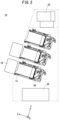
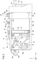
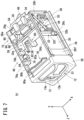
- FIG. 6 , FIG. 7 , and FIG. 8 are diagrams showing a manner in which the mobile battery 12 is accommodated in the slot 14.
- the user grips a handle 13 of the mobile battery 12 and inserts the mobile battery 12 into the insertion opening 28 (see FIG. 6 ).
- the user places the entirety of the mobile battery 12 in a state in which it is inserted into the slot 14 (see FIG. 7 ).
- the user further pushes in the mobile battery 12 (see FIG. 8 ). Consequently, the battery tray 32 moves together with the mobile battery 12 to the negative side in the Z-axis direction, and the connector 15 of the mobile battery 12 and the connector 34 of the slot 14 are connected to each other.
- the state of the slot 14 shown in FIG. 7 may be described as a state in which the mobile battery 12 is inserted into the slot 14.
- the state of the slot 14 shown in FIG. 8 may be described as a state in which the mobile battery 12 is pushed into the slot 14.
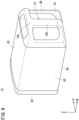
- FIG. 9 is a perspective view of the mobile battery 12.
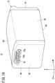
- FIG. 10 is a perspective view of the mobile battery 12.
- FIG. 11 is a view of the mobile battery 12 as seen from the side of a first surface S1 of the mobile battery 12.
- the outer shape of the mobile battery 12 is formed substantially in the shape of a rectangular parallelepiped.
- the mobile battery 12 includes the first surface S1 and the second surface S2, which are side surfaces respectively at both ends of the mobile battery 12 in the longitudinal direction thereof.
- the mobile battery 12 includes a third surface S3 and a fourth surface S4, which are side surfaces substantially perpendicular to the first surface S1 and the second surface S2.
- the third surface S3 and the fourth surface S4 are arranged on sides that are opposite to each other.
- the mobile battery 12 includes a fifth surface S5 and a sixth surface S6, which are side surfaces substantially perpendicular to the first surface S1 and the second surface S2.
- the fifth surface S5 and the sixth surface S6 are arranged on sides that are opposite to each other.
- the longitudinal direction of the mobile battery 12 is defined as a W-axis direction, and the side of the first surface S1 is defined as a positive side.
- the direction connecting the third surface S3 and the fourth surface S4 of the mobile battery 12 is defined as a V-axis direction, and the direction from the fourth surface S4 toward the third surface S3 is defined as a positive direction.
- the direction connecting the fifth surface S5 and the sixth surface S6 of the mobile battery 12 is defined as a U-axis direction, and the direction from the fifth surface S5 toward the sixth surface S6 is defined as a positive direction.
- the handle 13 is provided on the first surface S1 of the mobile battery 12.
- the first surface S1 and the handle 13 are formed together in an integral manner.
- the user grips the handle 13, and carries out insertion or removal of the mobile battery 12 into or out of the slot 14 of the battery exchange device 10.
- the handle 13 corresponds to a grip member of the present invention.
- the handle 13 is formed in a T-shape when the mobile battery 12 is viewed from the side of the first surface S1.
- the handle 13 includes a first portion 13a and a second portion 13b.
- the first portion 13a extends in the U-axis direction. In other words, the first portion 13a extends in the direction from the fifth surface S5 toward the sixth surface S6.
- the second portion 13b extends in the V-axis direction.
- the second portion 13b extends in the direction from the third surface S3 toward the fourth surface S4.
- the first portion 13a is arranged more on the positive side in the V-axis direction than the center of the first surface S1.
- the first portion 13a is arranged on the first surface S1 and between the third surface S3 and the fourth surface S4. Furthermore, on the first surface S1, the first portion 13a is arranged at a position in closer to the third surface S3 than the fourth surface S4.
- An intermediate part of the first portion 13a in the longitudinal direction (the U-axis direction) is separated from the first surface S1 toward the positive side in the W-axis direction.
- a space is provided between the first portion 13a and the first surface S1. Both ends of the first portion 13a in the longitudinal direction (the U-axis direction) are directly connected to the first surface S1.
- the second portion 13b is arranged at the central part of the first surface S1.
- the second portion 13b is arranged on the first surface S1 and between the fifth surface S5 and the sixth surface S6.
- the second portion 13b is arranged on the first surface S1, in a manner so that the distance between the second portion 13b and the fifth surface S5 and the distance between the second portion 13b and the sixth surface S6 are substantially the same.
- a first end part (an end part on the positive side in the V-axis direction) in close proximity to the third surface S3, and an intermediate part are separated from the first surface S1 toward the positive side in the W-axis direction.
- a space is provided between the second portion 13b and the first surface S1.
- the aforementioned first end part (the end part on the positive side in the V-axis direction) is connected to the first portion 13a.
- the second portion 13b is connected to the central part of the first portion 13a.
- a second end part (an end part on the negative side in the V-axis direction) in close proximity to the fourth surface S4 is directly connected to the first surface S1.
- the connector 15 is provided on the second surface S2 of the mobile battery 12. In the V-axis direction, the connector 15 is arranged more on the positive side in the V-axis direction than the center of the second surface S2. In other words, the connector 15 is arranged on the second surface S2 and between the third surface S3 and the fourth surface S4. Furthermore, on the second surface S2, the connector 15 is arranged at a position closer to the third surface S3 than the fourth surface S4.
- the third surface S3 of the mobile battery 12 is formed in a curved shape that is convex toward an outer side.
- Each of the fourth surface S4, the fifth surface S5, and the sixth surface S6 of the mobile battery 12 is formed in a planar shape.
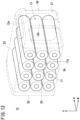
- FIG. 12 is a transparent view of the mobile battery 12.
- a plurality of cells 17 are accommodated inside the mobile battery 12.
- Each of the cells 17 has a substantially cylindrical outer shape.
- Each of the cells 17 includes electrodes 17a at both ends thereof in the longitudinal direction.
- the longitudinal direction of each of the cells 17 substantially coincides with the U-axis direction.
- the longitudinal direction of each of the cells 17 substantially coincides with a direction perpendicular to the fifth surface S5 and the sixth surface S6 of the mobile battery 12.
- each of the cells 17 can be placed inside the mobile battery 12, in a state with one of the two electrodes 17a of each of the cells 17 being made to face toward the fifth surface S5 of the mobile battery 12. Further, each of the cells 17 can be placed inside the mobile battery 12, in a state with the other one of the two electrodes 17a of each of the cells 17 being made to face toward the sixth surface S6 of the mobile battery 12.
- the fifth surface S5 and the sixth surface S6 are formed in a planar shape. Therefore, in comparison with a case in which the fifth surface S5 and the sixth surface S6 are formed in a curved shape, the electrodes 17a can be brought into closer proximity to the fifth surface S5 and the sixth surface S6. Consequently, the heat of the electrodes 17a, which have a comparatively high temperature within the cell 17, can be efficiently released from the fifth surface S5 and the sixth surface S6.
- the user grips the second portion 13b of the handle 13 with the second finger (the index finger), the third finger (the middle finger), the fourth finger (the ring finger), and the fifth finger (the little finger).
- the user places his or her first finger (the thumb) on the first portion 13a.
- the third surface S3 of the mobile battery 12 is positioned upward.
- the posture of the mobile battery 12 with the third surface S3 thereof facing upward is the correct posture of the mobile battery 12.
- the user is also capable of gripping the second portion 13b of the handle 13 with the first, the second, the third, the fourth, and the fifth fingers, with the first finger facing toward a side opposite to the first portion 13a of the handle 13.
- the fourth surface S4 of the mobile battery 12 is positioned upward.
- the user finds it difficult to apply a force to lift the mobile battery 12.
- the handle 13 being formed in a T shape, it is possible to guide the direction in which the user grips the handle 13.
- the third surface S3 of the mobile battery 12 can be positioned upward.
- the mobile battery 12 can be inserted into the slot 14 in the correct posture.
- a force that acts on the third surface S3 that is positioned upward is larger than a force that acts on the fourth surface S4 that is positioned downward.
- the third surface S3 of the mobile battery 12 that is formed in a curved shape has a higher rigidity than the fourth surface S4 that is formed in a planar shape. Therefore, the rigidity of the mobile battery 12 can be ensured.
- the third surface S3 of the mobile battery 12 is higher in rigidity than the fourth surface S4. Therefore, there is no need to separately provide a reinforcing member or the like at the connecting portion between the first portion 13a and the first surface S1. Consequently, an increase in the number of parts of the mobile battery 12 can be suppressed.
- the fourth surface S4 is formed in a planar shape.
- the cells 17 can be arranged in closer proximity to the fourth surface S4.
- the heat generated in the cells 17 can be efficiently released from the fourth surface S4.
- the connector 34 of the slot 14 is inserted into the connector 15. At this time, a force acts on the connector 15 from the connector 34.
- the connector 34 is arranged at a position closer to the third surface S3 than the fourth surface S4.
- the third surface S3 of the mobile battery 12 is higher in rigidity than the fourth surface S4. Therefore, there is no need to separately provide a reinforcing member or the like at the connector 15. Consequently, an increase in the number of parts of the mobile battery 12 can be suppressed.
- the tray lock mechanism 38 In a state in which the mobile battery 12 is inserted into the slot 14, the tray lock mechanism 38 allows movement of the battery tray 32 to the negative side in the Z-axis direction. In a state in which the mobile battery 12 is not inserted into the slot 14, the tray lock mechanism 38 restricts movement of the battery tray 32 to the negative side in the Z-axis direction.
- FIG. 13 is a cross-sectional view of the slot 14.
- the slot 14 shown in FIG. 13 is cut along a plane parallel to the YZ plane.
- FIG. 13 shows a state in which the mobile battery 12 is inserted into the slot 14.
- the mobile battery 12 is shown in the form of a partial cross-sectional view.
- the tray lock mechanism 38 is installed on a side surface of the slot 14 on the positive side in the Y-axis direction.
- the tray lock mechanism 38 includes a latch 58 and a striker 60.
- the latch 58 is installed on a side surface of the tray main body 32f of the battery tray 32 on the positive side in the Y-axis direction.
- the latch 58 includes a latch bolt 58a, a latch bolt holder 58b, a spring 58c, and a lever 58d.
- the latch bolt 58a is provided so as to be capable of moving in the Y-axis direction within the latch bolt holder 58b.
- the latch bolt holder 58b is fixed to the battery tray 32.
- the spring 58c is provided inside the latch bolt holder 58b.
- the latch bolt 58a is biased by the spring 58c toward the positive side in the Y-axis direction.
- An end part of the lever 58d on the positive side in the Z-axis direction is connected to the latch bolt 58a.
- An end part of the lever 58d on the negative side in the Z-axis direction is provided so as to extend from a through hole 32c into the interior of the battery tray 32.
- the through hole 32c is formed in a side surface of the battery tray 32 on the positive side in the Y-axis direction.
- the lever 58d is provided so as to be capable of rotating, at an intermediate part thereof in the Z-axis direction, about a rotation shaft 58e with respect to the latch bolt holder 58b.
- the rotation shaft 58e is fixed to the latch bolt holder 58b.
- the striker 60 is fixed to the surface of the battery holder 30 on the positive side in the Y-axis direction. As shown in FIG. 4 , the striker 60 is formed to extend from the battery holder 30 beyond the end part of the battery holder 30 to the negative side in the Z-axis direction. As shown in FIG. 13 , an end part of the striker 60 on the negative side in the Z-axis direction includes an engagement member 60a. The engagement member 60a is formed to extend in the X-axis direction. In a state in which the battery tray 32 is moved maximally to the positive side in the Z-axis direction, the latch bolt 58a is positioned more on the positive side in the Z-axis direction than the engagement member 60a of the striker 60.
- the latch bolt 58a is positioned on the positive side in the Z-axis direction with respect to the engagement member 60a of the striker 60.
- the tray lock mechanism 38 restricts the movement of the battery tray 32 to the negative side in the Z-axis direction.
- a state is defined as a state in which the latch bolt 58a of the latch 58 is positioned more on the positive side in the Z-axis direction than the engagement member 60a of the striker 60, and further, is a state (a locked state) in which the distal end of the latch bolt 58a on the positive side in the Y-axis direction is positioned more on the positive side in the Y-axis direction than the engagement member 60a.
- the tray lock mechanism 38 allows the movement of the battery tray 32 to the negative side in the Z-axis direction.
- Such a state is defined as a state in which the distal end of the latch bolt 58a of the latch 58 on the positive side in the Y-axis direction is positioned more on the negative side in the Y-axis direction than the engagement member 60a of the striker 60.
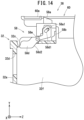
- FIG. 14 is a cross-sectional view of the tray lock mechanism 38 in a locked state.
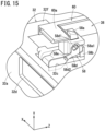
- FIG. 15 is a cross-sectional perspective view of the tray lock mechanism 38 in the locked state.
- the tray lock mechanism 38 shown in FIG. 14 and FIG. 15 is cut along a plane parallel to the YZ plane.
- the latch bolt 58a includes a connecting shaft 58a1.
- the connecting shaft 58a1 penetrates through the latch bolt holder 58b in the X-axis direction, and extends to an outer side of the latch bolt holder 58b.
- An elongated hole 58d1 is formed at the end part of the lever 58d on the positive side in the Z-axis direction.
- the connecting shaft 58a1 of the latch bolt 58a is inserted into the elongated hole 58d1.
- the lever 58d includes an inclined surface 58d2.
- the inclined surface 58d2 is formed on the positive side in the Z-axis direction of the lever 58d.
- the inclined surface 58d2 is formed on a portion of the lever 58d that is positioned in the interior of the battery tray 32.
- the inclined surface 58d2 is formed in a manner so as to be positioned on an inner side of the battery tray 32 as it extends to the negative side in the Z-axis direction.
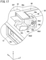
- FIG. 16 is a cross-sectional view of the tray lock mechanism 38 in an unlocked state.
- FIG. 17 is a cross-sectional perspective view of the tray lock mechanism 38 in the unlocked state.
- the tray lock mechanism 38 shown in FIG. 16 and FIG. 17 is cut along a plane parallel to the YZ plane.
- the lever 58d when the mobile battery 12 is inserted into the slot 14, the lever 58d is pressed by the third surface S3 of the mobile battery 12, and thereby rotates about the rotation shaft 58e.
- the position of the lever 58d that is pressed by the third surface S3 is on the negative side in the Z-axis direction with respect to the rotation shaft 58e, and further, is on the negative side in the Y-axis direction with respect to the rotation shaft 58e.
- the portion of the lever 58d more on the positive side in the Z-axis direction than the rotation shaft 58e moves to the negative side in the Y-axis direction.
- the connecting shaft 58a1 of the latch bolt 58a is pulled toward the negative side in the Y-axis direction. Consequently, the latch bolt 58a moves to the negative side in the Y-axis direction. As a result, an end part of the latch bolt 58a on the positive side in the Y-axis direction is positioned on the negative side in the Y-axis direction with respect to the engagement member 60a of the striker 60.
- the latch bolt 58a is positioned on the positive side in the Z-axis direction with respect to the engagement member 60a of the striker 60.
- the latch bolt 58a and the engagement member 60a do not contact each other. Therefore, in the case that the battery tray 32 rattles with respect to the battery holder 30, an excessive force does not act on the latch 58 and the striker 60.
- the tray lock mechanism 38 has a function of preventing the mobile battery 12 from being inserted in reverse.
- the user is required to insert the mobile battery 12 into the slot 14 with the third surface S3 thereof facing upward. This is in order to align the connector 34 of the slot 14 with the connector 15 of the mobile battery 12.
- the connector 15 of the mobile battery 12 is not connected to the connector 34 of the slot 14.
- the tray lock mechanism 38 maintains the locked state, and restricts the movement of the battery tray 32 in the Z-axis direction.
- FIG. 18A and FIG. 18B are schematic diagrams showing the shapes of the insertion opening 28, the battery holder 30, the battery tray 32, and the mobile battery 12 as seen from the positive side in the Z-axis direction.
- An inner peripheral surface of the insertion opening 28, an inner peripheral surface of the battery holder 30, and an inner peripheral surface of the battery tray 32 are formed in substantially the same shape when viewed from the positive side in the Z-axis direction.
- the side surface, on the negative side in the Y-axis direction, of the inner peripheral surface of the insertion opening 28, the inner peripheral surface of the battery holder 30, and the inner peripheral surface of the battery tray 32 is defined as a side surface T1.
- the side surface on the inner peripheral surface of the insertion opening 28, the inner peripheral surface of the battery holder 30, and the inner peripheral surface of the battery tray 32 is defined as a side surface T2.
- FIG. 18A shows a state in which the mobile battery 12 is inserted into the slot 14 with the third surface S3 thereof facing upward.
- the posture of the mobile battery 12 at this time is defined as a first posture.
- FIG. 18B shows a state in which the mobile battery 12 is inserted into the slot 14 with the third surface S3 thereof facing downward.
- the posture of the mobile battery 12 at this time is defined as a second posture.
- the fourth surface S4, the fifth surface S5, and the sixth surface S6 are formed in a planar shape.
- the third surface S3 that faces toward the fourth surface S4 is formed in a curved shape that is convex toward the outer side.
- the posture with the third surface S3 facing upward is the correct posture when the mobile battery 12 is inserted into the slot 14.
- the side surface T1 is formed in a shape that follows along the curved shape of the third surface S3 of the mobile battery 12.
- the mobile battery 12 is positioned more on the negative side in the Y-axis direction than in a case in which the mobile battery 12 is inserted into the slot 14 in the first posture. Therefore, a size G2 of the gap between the side surface T2 and the mobile battery 12 in the case that the mobile battery 12 is inserted into the slot 14 in the second posture becomes larger than a size G1 of the gap between the side surface T2 and the mobile battery 12 in the case that the mobile battery 12 is inserted into the slot 14 in the first posture.
- the lever 58d of the latch 58 of the tray lock mechanism 38 is provided so as to extend, from the through hole 32c of the battery tray 32 on the positive side in the Y-axis direction, into the inner side of the inner peripheral surface of the battery tray 32.
- the fourth surface S4 of the mobile battery 12 does not come into contact with the lever 58d of the latch 58. Therefore, the tray lock mechanism 38 does not become capable of being unlocked. Consequently, the user is incapable of pushing in the mobile battery 12. As a result, it is possible to prevent the mobile battery 12 from being inserted in reverse.
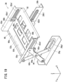
- FIG. 19 is a perspective view of the tray retention mechanism 36.
- the X-links 44 are provided respectively on the positive side in the X-axis direction and the negative side in the X-axis direction with respect to the tray bracket 52.
- Each of the X-links 44 includes a link 62a and a link 62b.
- End parts of the links 62a on the negative side in the Z-axis direction are mounted onto end parts of the side frames 26g and 26h on the positive side in the Y-axis direction.
- Pins 62a1 are provided at end parts of the links 62a on the positive side in the Z-axis direction.
- the pins 62a1 extend toward the inner side of the slot 14 in the X-axis direction.
- the pins 62a1 are inserted into guides 52a1 that are formed on side surfaces 52a of the tray bracket 52.
- the guides 52a1 are formed in the shape of elongated holes that extend in the Y-axis direction.
- the end parts of the links 62a on the positive side in the Z-axis direction are guided in the Y-axis direction along the guides 52a1.
- End parts of the links 62b on the positive side in the Z-axis direction are mounted onto end parts of the side surfaces 52a of the tray bracket 52 on the positive side in the Y-axis direction.
- Pins 62b1 are provided at end parts of the links 62b on the negative side in the Z-axis direction.
- the pins 62b1 extend toward the inner side of the slot 14 in the X-axis direction.
- the pins 62b1 are inserted into guides 26g1 and 26h1 that are formed on the side frames 26g and 26h.
- the guides 26g1 and 26h1 are formed in the shape of elongated holes that extend in the Y-axis direction.
- the end parts of the links 62b on the negative side in the Z-axis direction are guided in the Y-axis direction along the guides 26g1 and 26h1.
- Central parts of the links 62a in the longitudinal direction are connected to central parts of the links 62b in the longitudinal direction.
- the links 62a and the links 62b are capable of being rotated relatively about the connection locations.
- the X-link 44 on the negative side in the X-axis direction with respect to the tray bracket 52, and the X-link 44 on the positive side in the X-axis direction with respect to the tray bracket 52 are connected by a rod 64a.
- the rod 64a is connected to the respective X-links 44 at the connection locations between the links 62a and 62b.
- the X-link 44 on the negative side in the X-axis direction with respect to the tray bracket 52, and the X-link 44 on the positive side in the X-axis direction with respect to the tray bracket 52 are connected by a rod 64b.
- the rod 64a is connected to the respective X-links 44 at the end parts of the links 62a on the positive side in the Z-axis direction.
- the strength of the X-links 44 with respect to forces in the X-axis direction can be ensured by the rod 64a and the rod 64b.
- a through hole 32d is formed in the bottom part 32a of the tray main body 32f of the battery tray 32.
- the through hole 32d is formed in the bottom part 32a closer to the positive side in the Y-axis direction.
- a through hole 52c is formed in the tray bracket 52.
- the through hole 52c is formed at a position corresponding to the through hole 32d of the tray main body 32f.
- a shutter 66 is arranged between the bottom part 32a of the tray main body 32f and the tray bracket 52.
- the shutter 66 includes a main body portion 66a and a connecting portion 66b.
- the main body portion 66a is a flat plate shaped member. A portion of the main body portion 66a closer to the negative side in the Y-axis direction is hollowed out. In accordance with this feature, the weight of the shutter 66 can be reduced. Moreover, it should be noted that the main body portion 66a need not necessarily be hollowed out.
- the connecting portion 66b is formed in the main body portion 66a.
- the connecting portion 66b is formed at an end part of the main body portion 66a on the negative side in the Y-axis direction.
- the connecting portion 66b is formed on each of both sides in the X-axis direction.
- the connecting portion 66b is formed so as to project out from the main body portion 66a toward the positive side in the Z-axis direction.
- a cutout portion 66c is formed in the portion of the main body portion 66a where the connecting portion 66b is formed.
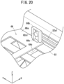
- FIG. 20 is an enlarged view of the connecting portion 66b of the shutter 66 and the vicinity thereof.
- the pin 62a1 of the link 62a is inserted into the connecting portion 66b from the positive side in the X-axis direction. Consequently, the connecting portion 66b and the link 62a are connected to each other.
- the shutter 66 is capable of moving in the Y-axis direction together with the link 62a.
- FIG. 21 is a cross-sectional view of the slot 14.
- the slot 14 shown in FIG. 21 is cut along a plane parallel to the YZ plane.
- FIG. 21 shows the slot 14 in a state in which the battery tray 32 is positioned foremost on the negative side in the Z-axis direction.
- an outline of the mobile battery 12 is indicated by the two-dot dashed line, in a manner so that the connector 34 and the like can be easily seen.
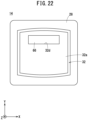
- FIG. 22 and FIG. 23 are front views of the slot 14.
- FIG. 22 shows the slot 14 in a state in which the battery tray 32 is positioned foremost on the positive side in the Z-axis direction.
- FIG. 22 shows the slot 14 in a state in which the battery tray 32 is positioned foremost on the positive side in the Z-axis direction.
- the state in which the battery tray 32 is positioned foremost on the negative side in the Z-axis direction indicates a state in which the battery tray 32 is in contact with an end surface of the battery holder 30 on the negative side in the Z-axis direction. Further, the state in which the battery tray 32 is positioned foremost on the negative side in the Z-axis direction indicates a state in which the battery tray 32 is in contact with the stopper 46.
- the shutter 66 moves in the Y-axis direction together with the link 62a.
- the shutter 66 blocks communication between the through hole 52c of the tray bracket 52 and the through hole 32d of the tray main body 32f. In accordance with this feature, foreign matter can be prevented from entering the connector 34 from the battery tray 32.
- the shutter 66 opens. Consequently, the through hole 32d of the tray main body 32f and the through hole 52c of the tray bracket 52 are placed in communication with each other.
- the connector 34 passes through the through hole 52c of the tray bracket 52 and the through hole 32d of the battery tray 32, and enters the interior of the battery tray 32. Consequently, the connector 34 of the slot 14 is connected to the connector 15 of the mobile battery 12 that is retained in the battery tray 32.
- the gas spring 50 of the tray retention mechanism 36 is filled with a gas.
- the tray retention mechanism 36 has a damper function and a spring function.
- a damping force is generated that prevents the displacement of the tray bracket 52 in the Z-axis direction.
- the spring function the tray bracket 52 is biased toward the positive side in the Z-axis direction.
- the gas spring 50 accumulates energy. Further, at a time when the battery tray 32 moves to the positive side in the Z-axis direction, the gas spring 50 releases the accumulated energy.
- the gas spring 50 accumulates energy as the pressure of the gas enclosed in the gas spring 50.
- a metal spring may be used instead of the gas spring 50.
- energy is accumulated as the elastic force of the spring.
- the inclination at which the slot 14 is installed in the battery exchange device 10 differs depending on the model of the battery exchange device 10.
- the force from the mobile battery 12 that acts in the Z-axis direction on the battery tray 32 changes in accordance with the inclination at which the slot 14 is installed in the battery exchange device 10. Therefore, the damper load of the gas spring 50 needs to be set in accordance with the inclination at which the slot 14 is installed in the battery exchange device 10.
- the spring bracket 54a supports the gas spring 50.
- the damper load that acts on the battery tray 32 from the gas spring 50 increases as the inclination of the gas spring 50 with respect to the Z-axis direction decreases.
- the damper load that acts on the battery tray 32 from the gas spring 50 can be changed.
- the air dampers 48 of the tray retention mechanism 36 generate a damping force so as to prevent the tray bracket 52 from being displaced to the negative side in the Z-axis direction.
- the air damper 48 includes a cylindrical columnar shaped plunger 48a. At a time when the tray bracket 52 moves to the negative side in the Z-axis direction, the tray bracket 52 comes into contact with the plunger 48a. At this time, a damping force acts on the tray bracket 52 from the plunger 48a toward the positive side in the Z-axis direction. In accordance with this feature, the air damper 48 absorbs the force input from the tray bracket 52.
- the stopper 46 of the tray retention mechanism 36 restricts the movement of the battery tray 32 to the negative side in the Z-axis direction. At a position where the battery tray 32 has moved maximally to the negative side in the Z-axis direction, the tray bracket 52 comes into contact with the stopper 46. In accordance with this feature, the movement of the battery tray 32 to the negative side in the Z-axis direction is restricted. Therefore, it is possible to prevent an excessive force from acting on the connector 34 from the mobile battery 12.
- the battery lock mechanism 40 in a state in which the mobile battery 12 is pushed into the slot 14, restricts the movement of the mobile battery 12 to the positive side in the Z-axis direction. Consequently, the state in which the mobile battery 12 is pushed into the slot 14 is maintained.
- FIG. 24 is a cross-sectional view of the slot 14.
- the slot 14 shown in FIG. 24 is cut along a plane parallel to the YZ plane.
- FIG. 25 and FIG. 26 are enlarged perspective views of the battery lock mechanism 40.
- FIG. 25 shows a state in which the mobile battery 12 is not inserted into the slot 14.
- FIG. 26 shows a state in which the mobile battery 12 is pushed into the slot 14.
- the battery lock mechanism 40 is installed on the side surface of the slot 14 on the positive side in the Y-axis direction.
- the battery lock mechanism 40 includes a shaft 68, a stopper drive unit 70, a stopper lock unit 72, and a stopper lock releasing unit 74.
- the shaft 68 is arranged so as to extend in the Z-axis direction.
- the shaft 68 is rotatably supported by two bearings 76a and 76b.
- the bearings 76a and 76b are installed on a side surface of the battery holder 30 on the positive side in the Y-axis direction.
- the stopper drive unit 70 includes flaps 78a and 78b, a lever 79, and a torsion spring 82.
- the flaps 78a and 78b are arranged between a plate 80a and a plate 80b.
- the plates 80a and 80b are installed on the side surface of the battery holder 30 on the positive side in the Y-axis direction.
- the flaps 78a and 78b include gears 78a1 and 78b1, arms 78a2 and 78b2, and stoppers 78a3 and 78b3.
- the flaps 78a and 78b are mounted in a rotatable manner to the plates 80a and 80b.
- the gears 78a1 and 78b1 are each formed with teeth on the outer circumference thereof.
- the gear 78a1 of the flap 78a and the gear 78b1 of the flap 78b mesh with each other.
- the flap 78b also rotates.
- the arms 78a2 and 78b2 extend from the gears 78a1 and 78b1.
- the stoppers 78a3 and 78b3 extend from the arms 78a2 and 78b2 toward the negative side in the Y-axis direction of the battery holder 30.
- the lever 79 is mounted on the shaft 68.
- the lever 79 and the shaft 68 rotate together in an integral manner.
- the torsion spring 82 is provided between the lever 79 and the plate 80b. When viewed from the positive side in the Z-axis direction, the torsion spring 82 biases the lever 79 such that the lever 79 rotates in a clockwise direction about the shaft 68.
- the lever 79 is connected to a connecting portion 78a4 of the flap 78a. Due to the lever 79 being rotated, the flap 78a rotates about the gear 78a1.
- the gear 78b1 that meshes with the gear 78a1 also rotates. Consequently, the flap 78b is made to rotate about the gear 78b1.
- FIG. 27 is a cross-sectional front view of the slot 14.
- the slot 14 shown in FIG. 27 is cut along a plane parallel to the XY plane.
- FIG. 28 is a front view of the slot 14.
- FIG. 27 and FIG. 28 show a state in which the flaps 78a and 78b are lowered.
- the stopper lock unit 72 includes a cam 84, a latch 86, and a coil spring 88.
- the cam 84 is provided on the negative side in the Z-axis direction of the shaft 68, and is capable of rotating integrally together with the shaft 68.
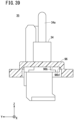
- FIG. 29 is a front view of the cam 84.
- FIG. 30 is a perspective view of the cam 84.
- the cam 84 includes a main body portion 84a and pawls 84b.
- the pawls 84b project out from the main body portion 84a toward the latch 86 (the negative side in the Z-axis direction).
- the main body portion 84a is a cylindrical member.
- a through hole 84a1 is formed in the center of the main body portion 84a.
- Each of the pawls 84b includes a contact surface 84b1 and an inclined surface 84b2.
- the contact surface 84b1 is a surface parallel to the axial direction of the cam 84 (the Z-axis direction).
- the inclined surface 84b2 is a surface that serves to connect an end part of the contact surface 84b1 on the negative side in the Z-axis direction and the main body portion 84a.
- the inclined surface 84b2 is a surface that is inclined with respect to the surface of the main body portion 84a on the negative side in the Z-axis direction.
- the pawls 84b are each formed over a range of about 75° in the circumferential direction.
- the latch 86 is provided inside a latch holder 90.
- the latch holder 90 is mounted on the main frame 26a.
- the latch 86 is provided so as to be capable of moving in the Z-axis direction.
- the latch 86 is provided so as to be incapable of rotating about the axis of the shaft 68.
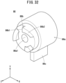
- FIG. 31 is a front view of the latch 86.
- FIG. 32 is a perspective view of the latch 86.
- the latch 86 includes a main body portion 86a, pawls 86b, and a pin 86c.
- the main body portion 86a is a cylindrical member, and includes a through hole 86a1 formed in the center thereof.
- the shaft 68 passes through the through hole 86a1.
- the pawls 86b project out from the main body portion 86a toward the cam 84 (the negative side in the Z-axis direction).
- the pin 86c extends from the main body portion 86a to the negative side in the Y-axis
- Each of the pawls 86b includes a contact surface 86b1 and an inclined surface 86b2.
- the contact surface 86b1 is a surface parallel to the axial direction of the latch 86 (the Z-axis direction).
- the inclined surface 86b2 is a surface that serves to connect an end part of the contact surface 86b1 on the positive side in the Z-axis direction and the main body portion 86a.
- the inclined surface 86b2 is a surface that is inclined with respect to the surface of the main body portion 86a on the negative side in the Z-axis direction.
- the pawls 86b are each formed over a range of about 75° in the circumferential direction.
- the shaft 68 passes through the through hole 86a1 of the latch 86.
- the shaft 68 is rotatably supported by the latch holder 90.
- the latch 86 is supported by the latch holder 90 so as to be capable of moving in the axial direction of the shaft 68 (the Z-axis direction).
- the latch 86 is supported in a manner so as to be incapable of rotating in the direction of rotation about the axis of the shaft 68.
- the latch 86 is biased toward the cam 84 by the coil spring 88 that is provided inside the latch holder 90.
- the contact surface 84b1 of the pawl 84b of the cam 84 comes into contact with the contact surface 86b1 of the pawl 86b of the latch 86. Consequently, the latch 86 restricts the rotation of the shaft 68 via the cam 84.
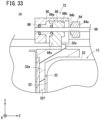
- FIG. 33 is an enlarged cross-sectional view of the stopper lock unit 72 of the slot 14 and the vicinity thereof.
- the slot 14 shown in FIG. 33 is cut along a plane parallel to the YZ plane.
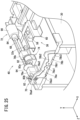
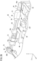
- FIG. 34 is an enlarged perspective view of the stopper lock unit 72 of the slot 14. In FIG. 34 , a portion of the coil spring 88 and a portion of the latch holder 90 are omitted.
- FIG. 33 and FIG. 34 show a state in which the mobile battery 12 is pushed into the slot 14.
- a pin 32e that projects out to the positive side in the Y-axis direction is formed on the surface of the tray main body 32f of the battery tray 32 on the positive side in the Y-axis direction.
- the pin 32e of the tray main body 32f presses the pin 86c of the latch 86.
- the latch 86 moves to the negative side in the Z-axis direction. Consequently, the pawl 86b of the latch 86 and the pawl 84b of the cam 84 become disengaged.
- the stopper lock releasing unit 74 includes a motor 92.
- the motor 92 is installed on the side surface of the battery holder 30 on the positive side in the Y-axis direction.
- a pinion 92a is mounted on the drive shaft of the motor 92.
- the pinion 92a meshes with a gear 94 that rotates integrally with the shaft 68.
- the shaft 68 can be made to rotate.
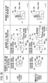
- FIG. 35 and FIG. 36 are tables showing movement of the cam 84 and the latch 86 in a direction of rotation, movement of the cam 84 and the latch 86 in an axial direction, and movement of the battery lock mechanism 40, at a time when the battery lock mechanism 40 changes from a lock released state to the locked state.
- Each of the diagrams shown in FIG. 35 and FIG. 36 is a schematic diagram.
- four states are shown including the lock released state, immediately prior to the locked state, a lowest point state, and the locked state.
- the lock released state indicates a state in which the mobile battery 12 is released from being locked by the battery lock mechanism 40.
- the immediately prior to the locked state indicates a state immediately prior to the mobile battery 12 being locked by the battery lock mechanism 40.
- the lowest point state indicates a state in which the mobile battery 12 is pushed maximally into the slot 14.
- the locked state indicates a state in which the mobile battery 12 is locked by the battery lock mechanism 40.
- a position P1 is taken to be the position of the latch 86 in the Z-axis direction in the lock released state (see FIG. 35 ).
- a biasing force is applied to the latch 86 from the coil spring 88 toward the positive side in the Z-axis direction, and the latch 86 is pressed against the cam 84.
- the pawl 84b of the cam 84 and the pawl 86b of the latch 86 engage with each other, and therefore, although the biasing force in the direction of rotation acts on the cam 84 from the torsion spring 82 via the shaft 68, the cam 84 does not rotate.
- the pin 32e of the tray main body 32f pushes the pin 86c of the latch 86.
- the latch 86 moves to the negative side in the Z-axis direction.
- a position P2 is taken to be the position of the latch 86 in the Z-axis direction immediately prior to the locked state (see FIG. 35 ).
- a biasing force in the direction of rotation acts on the cam 84 from the torsion spring 82 via the shaft 68.
- the cam 84 does not rotate.
- a position P3 is taken to be the position of the latch 86 in the Z-axis direction in the lowest point state (see FIG. 36 ).
- the latch 86 and the cam 84 are separated from each other, and the pawl 84b of the cam 84 and the pawl 86b of the latch 86 are disengaged. Therefore, the cam 84 is made to rotate by the biasing force of the torsion spring 82.
- the shaft 68 rotates together with the cam 84, and furthermore, the lever 79 rotates together with the shaft 68. Consequently, the flaps 78a and 78b are lowered.
- a gap occurs between the mobile battery 12 and the stoppers 78a3 and 78b3.
- the mobile battery 12 moves to the positive side in the Z-axis direction due to the force of the gas spring 50 pushing the battery tray 32 to the positive side in the Z-axis direction.
- the mobile battery 12 comes into contact with the stoppers 78a3 and 78b3 and becomes placed in the locked state.
- a position P4 is taken to be the position of the latch 86 in the Z-axis direction in the locked state (see FIG. 36 ).
- the latch 86 is pushed toward the cam 84 by the biasing force of the coil spring 88.
- FIG. 37 is a table showing movement of the cam 84 and the latch 86 in a direction of rotation, and movement of the cam 84 and the latch 86 in an axial direction, at a time when the battery lock mechanism 40 changes from the locked state to the lock released state.
- Each of the diagrams shown in FIG. 37 is a schematic diagram.
- three states are shown including the locked state, a state during release of the lock, and the lock released state.
- the locked state indicates a state in which the mobile battery 12 is locked by the battery lock mechanism 40.
- the state during release of the lock indicates a state in which the mobile battery 12 is midway during being released from being locked by the battery lock mechanism 40.
- the lock released state indicates a state in which the mobile battery 12 is released from being locked by the battery lock mechanism 40.
- the shaft 68 is rotated by the rotating force of the motor 92, and the cam 84 rotates integrally together with the shaft 68.
- the inclined surface 84b2 of the pawl 84b of the cam 84 presses the inclined surface 86b2 of the pawl 86b of the latch 86.
- the latch 86 moves to the negative side in the Z-axis direction from the position P4, which is the axial position of the latch 86 in the locked state.
- the locked state of the mobile battery 12 is released.
- the battery tray 32 moves to the positive side in the Z-axis direction due to the biasing force of the gas spring 50.
- the latch 86 also moves to the positive side in the Z-axis direction due to the biasing force of the coil spring 88. Consequently, the latch 86 is positioned at the position P1, which is the axial position of the latch 86 in the lock released state.
- the pawl 84b of the cam 84 and the pawl 86b of the latch 86 engage with each other.
- the battery lock mechanism 40 is arranged on the positive side in the Y-axis direction of the slot 14 together with the tray lock mechanism 38.
- a structure that projects out to the exterior of the frame 26 can be concentrated on the positive side in the Y-axis direction of the slot 14.
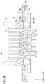
- FIG. 38 and FIG. 39 are cross-sectional views of the connector unit 35.
- the connector unit 35 includes the connector 34, a connector holder 96, a plate 98, and a coil spring 100.
- the connector 34 includes guide protruding portions 34a, terminals 34b, and a flange portion 34c.
- the guide protruding portions 34a are fitted into guide holes 15a (see FIG. 41 ) that are formed in the second surface S2 of the mobile battery 12.
- a pair of the guide protruding portions 34a are provided on both outer sides of the terminals 34b in the X-axis direction.
- the terminals 34b are fitted into non-illustrated terminal holes that are formed in the connector 15 of the mobile battery 12. Electrical power for charging the mobile battery 12 is supplied from the terminals 34b. Further, control signals for controlling the charging of the mobile battery 12 are transmitted from the terminals 34b.
- the flange portion 34c is accommodated in a concave portion 96b of the connector holder 96, which will be described later.
- FIG. 40 is a perspective view of the connector holder 96.
- the connector holder 96 includes a through hole 96a that passes therethrough in the Z-axis direction. As shown in FIG. 38 , the guide protruding portion 34a and the terminals 34b of the connector 34 are inserted into the through hole 96a.
- the connector holder 96 includes the concave portion 96b on the surface thereof on the negative side in the Z-axis direction.
- the flange portion 34c of the connector 34 is accommodated in the concave portion 96b.
- a tapered portion 96b1 is formed at the edge of the concave portion 96b.
- the plate 98 is fixed to the negative side in the Z-axis direction of the connector holder 96.
- the coil spring 100 is provided between the plate 98 and the connector 34.
- the connector 34 is biased toward the positive side in the Z-axis direction by the coil spring 100.
- FIG. 41 is a partial cross-sectional view showing a state in which the connector 34 of the connector unit 35 is connected to the connector 15 of the mobile battery 12.
- the connector 15 of the mobile battery 12 includes the guide holes 15a and terminal holes 15b.
- the guide holes 15a are fitted with the guide protruding portions 34a of the connector 34.
- the terminal holes 15b are fitted with the terminals 34b of the connector 34.
- the flange portion 34c of the connector 34 is in contact with the bottom surface of the concave portion 96b of the connector holder 96 due to the biasing force of the coil spring 100, as shown in FIG. 38 .
- the connector 34 moves to the negative side in the Z-axis direction with respect to the connector holder 96, in accordance with the force toward the negative side in the Z-axis direction that acts on the connector 34 from the mobile battery 12. Consequently, while the terminals 34b of the connector 34 and the terminal holes 15b of the mobile battery 12 are being fitted together, a force that presses the connector 34 toward the mobile battery 12 can be ensured.
- the flange portion 34c of the connector 34 is separated away from the bottom surface of the concave portion 96b of the connector holder 96. In accordance with this feature, even if the mobile battery 12 moves slightly within the slot 14, the terminals 34b of the connector 34 and the terminal holes 15b of the mobile battery 12 do not become disengaged.
- the flange portion 34c of the connector 34 which has separated away from the bottom surface of the concave portion 96b of the connector holder 96, moves toward the bottom surface of the concave portion 96b due to the biasing force of the coil spring 100.
- the flange portion 34c of the connector 34 is guided by the tapered portion 96b1 of the concave portion 96b of the connector holder 96, and thereby the connector 34 can be centered with respect to the connector holder 96.
- the connector unit 35 is arranged on the positive side in the Y-axis direction with respect to a central part of the slot 14 in the Y-axis direction.
- the connector unit 35 can be arranged at a position far away from the ground surface. Therefore, contact of water or the like with the connector unit 35 can be suppressed.
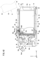
- FIG. 42 is a cross-sectional view of the slot 14.
- the slot 14 shown in FIG. 42 is cut along a plane parallel to the YZ plane.
- the handle 13 of the mobile battery 12 is positioned on the positive side in the Z-axis direction with respect to an edge of the insertion opening 28 on the positive side in the Y-axis direction. Further, the handle 13 is positioned on the negative side in the Z-axis direction with respect to an edge of the insertion opening 28 on the negative side in the Y-axis direction. Consequently, a portion of the handle 13 is exposed to the exterior of the slot 14. Therefore, the user can easily grip the handle 13 at a time when the user receives the mobile battery 12 from the battery exchange device 10. Further, the mobile battery 12 does not project out from the slot 14 to the positive side in the Z-axis direction. Therefore, at a time when the user receives the mobile battery 12 from the battery exchange device 10, a bottom surface 12a of the mobile battery 12 can be prevented from colliding with the mobile battery 12 that is inserted into the slot 14 located therebelow.
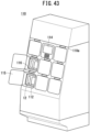
- FIG. 43 is an external schematic diagram of a battery energy storage 110.
- a plurality (eight in the present embodiment) of the mobile batteries 12 are accommodated in the battery energy storage 110.
- the mobile batteries 12 inside the battery energy storage 110 are fully charged at a normal time, and the electrical power stored in the mobile batteries 12 is discharged, for example, at the time of a power outage or the like.
- the mobile batteries 12 that are used in the battery energy storage 110 are the products that are repeatedly used in an electric motorcycle or the like, and become degraded, in a manner so that the state of health (SOH) thereof becomes no longer suitable for use in the electric motorcycle or the like.
- the mobile batteries 12 that are used in the battery energy storage 110 may be new products that have not been subjected to deterioration.
- a portion of the mobile batteries 12 that are used in the battery energy storage 110 may be deteriorated products, and the rest of the mobile batteries 12 may be new products.
- the battery energy storage 110 corresponds to an external device of the present invention.
- the battery energy storage 110 includes eight slots 112.
- the battery energy storage 110 includes a single operation panel 114.
- the mobile batteries 12 are accommodated in the slots 112. Unlike the battery exchange device 10 according to the first embodiment, taking out and insertion of the mobile batteries 12 is not carried out frequently in the battery energy storage 110.
- the mobile batteries 12 that are accommodated in the battery energy storage 110 for example, are replaced in the case that the mobile battery 12 has become damaged, or alternatively, in the case that the deterioration of the mobile battery 12 has progressed.
- An indicator 116 is provided above the slot 112.
- the indicator 116 displays the state of health of the mobile battery 12 that is accommodated in the slot 112 by illumination of colors, flashing, or the like.
- the operation panel 114 is a device that is operated by the user.
- the battery energy storage 110 includes a door 115 that closes the opening of each of the slots 112.
- the door 115 may be mounted thereon as an option.
- FIG. 44 is a cross-sectional view of the battery energy storage 110.
- the battery energy storage 110 includes a control device 117 located above the slots 112. The control device 117 controls charging, electrical power supply, and the like of the mobile batteries 12. At a time when the mobile battery 12 is charged, the control device 117 controls a non-illustrated AC/DC converter, and thereby converts AC electrical power supplied from a commercial electrical power source into DC electrical power and supplies the DC electrical power to the mobile battery 12. At a time when the mobile battery 12 is discharged, the control device 117 controls a non-illustrated DC/AC converter, and thereby converts the DC electrical power output from the mobile battery 12 into AC electrical power and supplies the AC electrical power to an external load.
- the battery energy storage 110 includes a utility space 119 located below the slots 112. A cooling device or the like may be installed in the utility space 119. The cooling device serves to cool the interior of the battery energy storage 110.
- the present embodiment will be described based on an X-axis, a Y-axis, and a Z-axis, which are defined in the following manner.
- the direction in which the mobile battery 12 is inserted into the slot 112 is defined as a Z-axis direction, and a side where the slot 112 opens onto a front surface 110a of the battery energy storage 110 is defined as a positive side.
- a direction parallel to a widthwise direction of the battery energy storage 110 is defined as an X-axis direction, and a right side thereof when viewed from the side on which the slot 112 opens onto the front surface 110a of the battery energy storage 110 is defined as a positive side.
- a direction perpendicular to the Z-axis and the X-axis is defined as a Y-axis direction, and an upper side thereof is defined as a positive side.
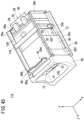
- FIG. 45 is a perspective view showing the slot 112 in a state with the mobile battery 12 accommodated therein.
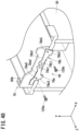
- FIG. 46 is a cross-sectional view showing the slot 112 in a state with the mobile battery 12 accommodated therein. The slot 112 shown in FIG. 46 is cut along a plane parallel to the YZ plane.
- FIG. 47 is a partial perspective view of a side surface of the slot 112 on the positive side in the Y-axis direction.
- the slot 112 of the battery energy storage 110 has substantially the same configuration as that of the slot 14 of the battery exchange device 10 according to the first embodiment. However, the slot 112 does not include a portion of the configuration of the tray retention mechanism 36, all of the configuration of the tray lock mechanism 38, and a portion of the configuration of the battery lock mechanism 40 of the slot 14. Specifically, the slot 112 does not include the X-links 44, the air dampers 48, and the gas spring 50 of the tray retention mechanism 36. On the other hand, the slot 112 includes the stoppers 46 of the tray retention mechanism 36. Further, the slot 112 does not include the latch 58 and the striker 60 of the tray lock mechanism 38.
- the slot 112 does not include the shaft 68, the stopper lock unit 72, and the stopper lock releasing unit 74 of the battery lock mechanism 40. Furthermore, the slot 112 does not include the lever 79 and the torsion spring 82 of the stopper drive unit 70. On the other hand, the slot 112 includes the flaps 78a and 78b of the stopper drive unit 70.
- the same constituent parts as in the configuration of the slot 14 of the battery exchange device 10 are designated by the same reference numerals as in the first embodiment, and description thereof is omitted.
- the slot 112 of the battery energy storage 110 includes a tray lock plate 118.
- the tray lock plate 118 is installed between the main frame 26a and the main frame 26d.
- a protruding part 120 is fixed to the tray main body 32f of the battery tray 32.
- the protruding part 120 is mounted on a side surface of the tray main body 32f on the positive side in the Y-axis direction.
- the protruding part 120 projects out toward the positive side in the Y-axis direction from the tray main body 32f.
- the protruding part 120 comes into contact with the tray lock plate 118 from the negative side in the Z-axis direction. In accordance with this feature, movement of the battery tray 32 to the positive side in the Z-axis direction is restricted.
- FIG. 48 is an enlarged perspective view of the battery lock mechanism 40.
- FIG. 49 is a cross-sectional front view of the slot 112. The slot 112 shown in FIG. 49 is cut along a plane parallel to the XY plane.
- FIG. 50 is a front view of the slot 112.
- the flaps 78a and 78b include bolt holes 78a5 and 78b5 in which bolts are fixed.
- the battery lock mechanism 40 is fixed by bolts 120a and 120b, in a state in which the flaps 78a and 78b are lowered.
- the mobile battery 12 comes into contact with the stoppers 78a3 and 78b3. Consequently, the movement of the mobile battery 12 to the positive side in the Z-axis direction is restricted. Thus, the mobile battery 12 can be prevented from being stolen.
- the insertion opening 28 may be mounted in a manner so that the insertion opening 28 is capable of being replaced singly.
- a plurality of types of the insertion openings 28 having different shapes may be prepared.
- the battery exchange device 10 need not necessarily include the doors 18.
- the battery exchange device 10 is configured to initiate charging of the mobile battery 12 when the user accommodates the mobile battery 12 in the slot 14 and closes the door 18.
- the battery exchange device 10 may initiate charging of the mobile battery 12 when a state is brought about in which the mobile battery 12 is pushed into the slot 14.
- the present invention is characterized by the battery (12) having a substantially rectangular parallelepiped outer shape, the battery comprising the first surface (S1) and the second surface (S2) which are side surfaces of both ends thereof in a longitudinal direction, the third surface (S3) which is a side surface substantially perpendicular to the first surface and the second surface, the fourth surface (S4) which is a side surface substantially perpendicular to the first surface and the second surface, and which is on an opposite side from the third surface, the fifth surface (S5) which is a side surface substantially perpendicular to the first surface, the second surface, the third surface, and the fourth surface, the sixth surface (S6) which is a side surface substantially perpendicular to the first surface and the second surface, and which is on an opposite side from the fifth surface, and the grip member (13) provided on the first surface, wherein the grip member includes the first portion (13a) that extends in a direction from the fifth surface toward the sixth surface, at a position between the third surface and the fourth surface and closer to the third surface than the fourth surface
- the fifth surface and the sixth surface may each have a planar shape
- the plurality of cells (17) each having an elongated shape may be included inside the battery
- each of the cells may include electrodes (17a) at both ends in the longitudinal direction thereof, and each of the cells may be arranged in a manner so that the longitudinal direction thereof is a direction substantially perpendicular to the fifth surface and the sixth surface.
- the third surface may have a curved shape that is convex toward an outer side
- the fourth surface, the fifth surface, and the sixth surface may each have a planar shape
- the above-described battery may further comprise, on the second surface, the connector (15) which carries out input and output of electrical power by being connected to the external device (10, 110), and the connector may be arranged at a position between the third surface and the fourth surface and closer to the third surface than the fourth surface.
Landscapes
- Chemical & Material Sciences (AREA)
- Chemical Kinetics & Catalysis (AREA)
- Electrochemistry (AREA)
- General Chemical & Material Sciences (AREA)
- Engineering & Computer Science (AREA)
- Power Engineering (AREA)
- Battery Mounting, Suspending (AREA)
- Connection Of Batteries Or Terminals (AREA)
- Primary Cells (AREA)
Abstract
Description
- The present invention relates to a battery including a grip member that is gripped by a user.
- In
WO 2018/235204 A1 , a battery unit is disclosed. The outer shape of the battery unit is formed substantially in the shape of a rectangular parallelepiped. The battery unit includes a grip member on an upper surface thereof. The battery unit is accommodated in an accommodating slot of an electric vehicle. The battery unit is used as an electrical power source for the electric vehicle. Further, the battery unit is accommodated in an accommodating slot of a charging station. Charging of the battery unit is carried out by the charging station. - The battery unit disclosed in
WO 2018/235204 A1 is provided with connection terminals on a bottom surface of a main body portion. In a state in which the battery unit is accommodated in the accommodating slot, the connection terminals are connected to terminals that are provided in the accommodating slot. The connection terminals of the battery unit are provided at a position that is shifted from the center of the bottom surface. Therefore, it is necessary that the battery unit be accommodated in a prescribed posture in the accommodating slot. However, the battery unit disclosed inWO 2018/235204 A1 has a problem in that the battery unit is accommodated in the accommodating slot in a posture that differs from such a prescribed posture. - The present invention has the object of solving the aforementioned problem.
- An aspect of the present invention is characterized by a battery having a substantially rectangular parallelepiped outer shape, the battery comprising a first surface and a second surface which are side surfaces of both ends thereof in a longitudinal direction, a third surface which is a side surface substantially perpendicular to the first surface and the second surface, a fourth surface which is a side surface substantially perpendicular to the first surface and the second surface, and which is on an opposite side from the third surface, a fifth surface which is a side surface substantially perpendicular to the first surface, the second surface, the third surface, and the fourth surface, a sixth surface which is a side surface substantially perpendicular to the first surface and the second surface, and which is on an opposite side from the fifth surface, and a grip member provided on the first surface, wherein the grip member includes a first portion configured to extend in a direction from the fifth surface toward the sixth surface, at a position between the third surface and the fourth surface and closer to the third surface than the fourth surface, and a second portion configured to extend in a direction from the third surface toward the fourth surface, at an intermediate part in the direction from the fifth surface toward the sixth surface, in a longitudinal direction of the first portion, an intermediate part of the first portion is separated from the first surface, and both end parts of the first portion are connected to the first surface, the second portion includes a first end part and a second end part which are end parts in a longitudinal direction of the second portion, and an intermediate part which is a portion between the first end part and the second end part, the first end part of the second portion is connected to the intermediate part of the first portion and is separated from the first surface, the intermediate part of the second portion is separated from the first surface, and the second end part of the second portion is directly connected to the first surface.
- According to the present invention, the battery unit can be accommodated in a prescribed posture in the accommodating slot.
-
-
FIG. 1 is an external schematic diagram of a battery exchange device; -
FIG. 2 is a cross-sectional view of the battery exchange device; -
FIG. 3 is a perspective view of a slot; -
FIG. 4 is a perspective view of the slot; -
FIG. 5 is a side view of the slot; -
FIG. 6 is a diagram showing a manner in which a mobile battery is accommodated in the slot; -
FIG. 7 is a diagram showing a manner in which the mobile battery is accommodated in the slot; -
FIG. 8 is a diagram showing a manner in which the mobile battery is accommodated in the slot; -
FIG. 9 is a perspective view of the mobile battery; -
FIG. 10 is a perspective view of the mobile battery; -
FIG. 11 is a view of the mobile battery as seen from the side of a first surface; -
FIG. 12 is a transparent view of the mobile battery; -
FIG. 13 is a cross-sectional view of the slot; -
FIG. 14 is a cross-sectional view of a tray lock mechanism in a locked state; -
FIG. 15 is a cross-sectional perspective view of the tray lock mechanism in the locked state; -
FIG. 16 is a cross-sectional view of the tray lock mechanism in an unlocked state; -
FIG. 17 is a cross-sectional perspective view of the tray lock mechanism in the unlocked state; -
FIG. 18A and FIG. 18B are schematic diagrams showing the shapes of an insertion opening, a battery holder, a battery tray, and a mobile battery as seen from a positive side in the Z-axis direction; -
FIG. 19 is a perspective view of a tray retention mechanism; -
FIG. 20 is an enlarged view of the vicinity of a connecting portion of a shutter; -
FIG. 21 is a cross-sectional view of the slot; -
FIG. 22 is a front view of the slot; -
FIG. 23 is a front view of the slot; -
FIG. 24 is a cross-sectional view of the slot; -
FIG. 25 is an enlarged perspective view of a battery lock mechanism; -
FIG. 26 is an enlarged perspective view of the battery lock mechanism; -
FIG. 27 is a cross-sectional front view of the slot; -
FIG. 28 is a front view of the slot; -
FIG. 29 is a front view of a cam; -
FIG. 30 is a perspective view of the cam; -
FIG. 31 is a front view of a latch; -
FIG. 32 is a perspective view of the latch; -
FIG. 33 is an enlarged cross-sectional view of a stopper lock unit of the slot and the vicinity thereof; -
FIG. 34 is an enlarged perspective view of the stopper lock unit; -
FIG. 35 is a table showing movement in a direction of rotation of the cam and the latch, movement in an axial direction of the cam and the latch, and movement of the battery lock mechanism; -
FIG. 36 is a table showing movement in the direction of rotation of the cam and the latch, movement in the axial direction of the cam and the latch, and movement of the battery lock mechanism; -
FIG. 37 is a table showing movement in the direction of rotation of the cam and the latch, and movement in the axial direction of the cam and the latch; -
FIG. 38 is a cross-sectional view of a connector unit; -
FIG. 39 is a cross-sectional view of the connector unit; -
FIG. 40 is a perspective view of a connector holder; -
FIG. 41 is a partial cross-sectional view showing a state in which a connector of the connector unit is connected to a connector of the mobile battery; -
FIG. 42 is a cross-sectional view of the slot; -
FIG. 43 is an external schematic diagram of a battery energy storage; -
FIG. 44 is a cross-sectional view of the battery energy storage; -
FIG. 45 is a perspective view showing the slot in a state with the mobile battery accommodated therein; -
FIG. 46 is a cross-sectional view showing the slot in a state with the mobile battery accommodated therein; -
FIG. 47 is a partial perspective view of a side surface of the slot on a positive side in the Y-axis direction; -
FIG. 48 is an enlarged perspective view of the battery lock mechanism; -
FIG. 49 is a cross-sectional front view of the slot; and -
FIG. 50 is a front view of the slot. -
FIG. 1 is an external schematic diagram of abattery exchange device 10. Thebattery exchange device 10 accommodates amobile battery 12 in the interior thereof. Thebattery exchange device 10 carries out charging of themobile battery 12. A user deposits themobile battery 12 having a low remaining power capacity (SOC: state of charge) in thebattery exchange device 10. The user receives another fully chargedmobile battery 12 from thebattery exchange device 10. Thebattery exchange device 10 corresponds to an external device of the present invention. Themobile battery 12 corresponds to a battery of the present invention. - The
battery exchange device 10 includes eightslots 14. Thebattery exchange device 10 includes asingle operation panel 16.Mobile batteries 12 are accommodated in theslots 14. When the user accommodates themobile battery 12 in theslot 14 and closes adoor 18, thebattery exchange device 10 initiates charging of themobile battery 12. Anindicator 20 is provided above theslot 14. Theindicator 20 displays the state of charge of themobile battery 12 that is accommodated in theslot 14 by illumination of colors, flashing, or the like. Theoperation panel 16 is a device that is operated by the user. By operating theoperation panel 16, for example, the user carries out payment of a fee or the like. - The
slot 14 opens on afront surface 10a of thebattery exchange device 10. Thefront surface 10a of thebattery exchange device 10 is inclined with respect to the vertical direction (the direction of gravity). In a state with the user standing facing thefront surface 10a, an upper part of thefront surface 10a is positioned more rearward than a lower part thereof. In accordance with this feature, the user is capable of leaning forward at a time when the user inserts themobile battery 12 into theslot 14. Therefore, it becomes easier to insert themobile battery 12 into theslot 14. -
FIG. 2 is a cross-sectional view of thebattery exchange device 10. Thebattery exchange device 10 includes acontrol device 22 located above theslots 14. Thecontrol device 22 controls charging or the like of themobile batteries 12. Thebattery exchange device 10 includes autility space 24 located below theslots 14. A cooling device or the like may be installed in theutility space 24. The cooling device serves to cool the interior of thebattery exchange device 10. -
FIG. 3 andFIG. 4 are perspective views of theslot 14.FIG. 5 is a side view of theslot 14. The present embodiment will be described based on an X-axis, a Y-axis, and a Z-axis, which are defined in the following manner. The direction in which themobile battery 12 is inserted into theslot 14 is defined as a Z-axis direction, and a side where theslot 14 opens onto thefront surface 10a of thebattery exchange device 10 is defined as a positive side. A direction parallel to a widthwise direction of thebattery exchange device 10 is defined as an X-axis direction, and a right side thereof when viewed from the side on which theslot 14 opens onto thefront surface 10a of thebattery exchange device 10 is defined as a positive side. A direction perpendicular to the Z-axis and the X-axis is defined as a Y-axis direction, and an upper side thereof is defined as a positive side. - The
slot 14 includes aframe 26, aninsertion opening 28, abattery holder 30, abattery tray 32, aconnector unit 35, atray retention mechanism 36, atray lock mechanism 38, and abattery lock mechanism 40. - The
frame 26 includesmain frames 26a to 26d, andside frames 26e to 26h (concerning theside frame 26f, refer toFIG. 6 ). Themain frames 26a to 26d are columnar members extending in the Z-axis direction. The outer appearance of theslot 14 is in the form of a substantially rectangular parallelepiped shape, the longitudinal direction of which is the Z-axis direction. Themain frames 26a to 26d are provided at respective locations corresponding to four sides that extend in the longitudinal direction of the rectangular parallelepiped. The twoside frames slot 14. The twoside frames slot 14. Theside frame 26e and theside frame 26g are fixed to themain frame 26a and themain frame 26b. Theside frame 26f and theside frame 26h are fixed to themain frame 26c and themain frame 26d. - The
insertion opening 28 is mounted on end parts of themain frames 26a to 26d on the positive side in the Z-axis direction. Theinsertion opening 28 is formed from a resin. Theinsertion opening 28 includes a through hole that penetrates therethrough in the Z-axis direction. In the Z-axis direction, the distal end of a portion of theinsertion opening 28 on the negative side in the Y-axis direction is positioned more on the positive side in the Z-axis direction than the distal end of a portion of theinsertion opening 28 on the positive side in the Y-axis direction. At a time when the user inserts themobile battery 12 into theslot 14, the user is capable of lifting up themobile battery 12, and placing a second surface S2 (refer toFIG. 6 ) of themobile battery 12 on a portion of theinsertion opening 28 on the negative side in the Y-axis direction. Thereafter, the user inserts themobile battery 12 into theslot 14. - The
battery holder 30 is provided on the negative side in the Z-axis direction with respect to theinsertion opening 28. Thebattery holder 30 is fixed to themain frames 26a to 26d. Both sides of thebattery holder 30 in the Z-axis direction are open. A space in the interior of thebattery holder 30 communicates with a space in the interior of theinsertion opening 28. The shape of the inner peripheral surface of thebattery holder 30 is formed substantially in the same shape as the shape of the inner peripheral surface of theinsertion opening 28. - The
battery tray 32 is provided on the negative side in the Z-axis direction with respect to thebattery holder 30. Thebattery tray 32 is capable of moving in the Z-axis direction along themain frames 26a to 26d. The movement of thebattery tray 32 to the positive side in the Z-axis direction is restricted by thebattery tray 32 coming into contact with a side surface of thebattery holder 30 on the negative side in the Z-axis direction. A surface of thebattery tray 32 on a side facing toward thebattery holder 30 is open. Thebattery tray 32 includes abottom part 32a (refer toFIG. 13 , to be described later) on an opposite side from the surface on the side facing toward thebattery holder 30. A space in the interior of thebattery tray 32 communicates with a space in the interior of thebattery holder 30, in a state in which thebattery tray 32 is in contact with the side surface of thebattery holder 30 on the negative side in the Z-axis direction. The shape of the inner peripheral surface of thebattery tray 32 is formed in substantially the same shape as the shape of the inner peripheral surface of thebattery holder 30. Aroller 32b is mounted respectively on a side surface of thebattery tray 32 on the positive side in the X-axis direction, and on a side surface of thebattery tray 32 on the negative side in the X-axis direction. Therollers 32b are provided on the negative side in the Y-axis direction of thebattery tray 32. At a time when thebattery tray 32 moves in the Z-axis direction, therollers 32b rotate on themain frame 26b and themain frame 26c. Consequently, therollers 32b serve to guide thebattery tray 32 in the Z-axis direction along themain frame 26b and themain frame 26c. - The
connector unit 35 includes aconnector 34. Theconnector 34 is connected to a connector 15 (refer toFIG. 10 , to be described later) on the second surface S2 of themobile battery 12. Consequently, electrical power is supplied from thebattery exchange device 10 to themobile battery 12. Theconnector unit 35 is installed in aconnector bracket 42. Theconnector bracket 42 is fixed to theside frame 26g and theside frame 26h at an end part of theslot 14 on the negative side in the Z-axis direction. Theconnector unit 35 is arranged in close proximity to a central part of theslot 14 in the X-axis direction. In the Y-axis direction, theconnector unit 35 is arranged closer to the positive side than the central part of theslot 14. - The
tray retention mechanism 36 is arranged on the negative side in the Z-axis direction of thebattery tray 32. Thetray retention mechanism 36 includes X-links 44,stoppers 46,air dampers 48, and agas spring 50. - The
battery tray 32 includes a traymain body 32f and atray bracket 52. Thetray bracket 52 is mounted on the negative side in the Z-axis direction of the traymain body 32f. Thetray retention mechanism 36 includes two X-links 44. One of the X-links 44 is provided on the negative side in the X-axis direction with respect to thebattery tray 32. This X-link 44 is disposed between thetray bracket 52 and theside frame 26g. The other one of the X-links 44 is provided on the positive side in the X-axis direction with respect to thebattery tray 32. This X-link 44 is disposed between thetray bracket 52 and theside frame 26h. - The
stoppers 46 are installed in astopper bracket 54. Thestopper bracket 54 is fixed to theside frame 26g and theside frame 26h at an end part of theslot 14 on the negative side in the Z-axis direction. Thestoppers 46 are arranged on a rear surface (on the positive side in the Y-axis direction) of theconnector unit 35. Twostoppers 46 are arranged while being separated from each other in the X-axis direction. - The air dampers 48 are installed in an
air damper bracket 56. Theair damper bracket 56 is fixed to theside frame 26g and theside frame 26h at an end part of theslot 14 on the negative side in the Z-axis direction. The air dampers 48 are arranged on the negative side in the Y-axis direction of theslot 14. Twoair dampers 48 are arranged while being separated from each other in the X-axis direction. - An end of the
gas spring 50 on the negative side in the Z-axis direction is mounted in aspring bracket 54a. An end part of thegas spring 50 on the positive side in the Z-axis direction is mounted in thetray bracket 52. Thespring bracket 54a is fixed to thestopper bracket 54. Thetray bracket 52 is fixed to thebattery tray 32. Thegas spring 50 is installed in a central part of theslot 14 in the X-axis direction. - The
tray lock mechanism 38 restricts the movement of thebattery tray 32 to the negative side in the Z-axis direction. Thetray lock mechanism 38 will be described in detail later. - The
battery lock mechanism 40, in a state in which themobile battery 12 is accommodated in theslot 14, restricts the movement of themobile battery 12 to the positive side in the Z-axis direction. Thebattery lock mechanism 40 will be described in detail later. -
FIG. 6 ,FIG. 7 , andFIG. 8 are diagrams showing a manner in which themobile battery 12 is accommodated in theslot 14. At a time when themobile battery 12 is accommodated in theslot 14, the user grips ahandle 13 of themobile battery 12 and inserts themobile battery 12 into the insertion opening 28 (seeFIG. 6 ). The user places the entirety of themobile battery 12 in a state in which it is inserted into the slot 14 (seeFIG. 7 ). Thereafter, the user further pushes in the mobile battery 12 (seeFIG. 8 ). Consequently, thebattery tray 32 moves together with themobile battery 12 to the negative side in the Z-axis direction, and theconnector 15 of themobile battery 12 and theconnector 34 of theslot 14 are connected to each other. Hereinafter, the state of theslot 14 shown inFIG. 7 may be described as a state in which themobile battery 12 is inserted into theslot 14. Further, the state of theslot 14 shown inFIG. 8 may be described as a state in which themobile battery 12 is pushed into theslot 14. -
FIG. 9 is a perspective view of themobile battery 12.FIG. 10 is a perspective view of themobile battery 12.FIG. 11 is a view of themobile battery 12 as seen from the side of a first surface S1 of themobile battery 12. - The outer shape of the
mobile battery 12 is formed substantially in the shape of a rectangular parallelepiped. Themobile battery 12 includes the first surface S1 and the second surface S2, which are side surfaces respectively at both ends of themobile battery 12 in the longitudinal direction thereof. Themobile battery 12 includes a third surface S3 and a fourth surface S4, which are side surfaces substantially perpendicular to the first surface S1 and the second surface S2. The third surface S3 and the fourth surface S4 are arranged on sides that are opposite to each other. Themobile battery 12 includes a fifth surface S5 and a sixth surface S6, which are side surfaces substantially perpendicular to the first surface S1 and the second surface S2. The fifth surface S5 and the sixth surface S6 are arranged on sides that are opposite to each other. - In describing the configuration of the
mobile battery 12, a U-axis, a V-axis, and a W-axis, which are defined in the following manner, are used. The longitudinal direction of themobile battery 12 is defined as a W-axis direction, and the side of the first surface S1 is defined as a positive side. The direction connecting the third surface S3 and the fourth surface S4 of themobile battery 12 is defined as a V-axis direction, and the direction from the fourth surface S4 toward the third surface S3 is defined as a positive direction. The direction connecting the fifth surface S5 and the sixth surface S6 of themobile battery 12 is defined as a U-axis direction, and the direction from the fifth surface S5 toward the sixth surface S6 is defined as a positive direction. - The
handle 13 is provided on the first surface S1 of themobile battery 12. The first surface S1 and thehandle 13 are formed together in an integral manner. The user grips thehandle 13, and carries out insertion or removal of themobile battery 12 into or out of theslot 14 of thebattery exchange device 10. Thehandle 13 corresponds to a grip member of the present invention. - As shown in
FIG. 11 , thehandle 13 is formed in a T-shape when themobile battery 12 is viewed from the side of the first surface S1. Thehandle 13 includes afirst portion 13a and asecond portion 13b. Thefirst portion 13a extends in the U-axis direction. In other words, thefirst portion 13a extends in the direction from the fifth surface S5 toward the sixth surface S6. Thesecond portion 13b extends in the V-axis direction. Thesecond portion 13b extends in the direction from the third surface S3 toward the fourth surface S4. - In the V-axis direction, the
first portion 13a is arranged more on the positive side in the V-axis direction than the center of the first surface S1. In other words, thefirst portion 13a is arranged on the first surface S1 and between the third surface S3 and the fourth surface S4. Furthermore, on the first surface S1, thefirst portion 13a is arranged at a position in closer to the third surface S3 than the fourth surface S4. An intermediate part of thefirst portion 13a in the longitudinal direction (the U-axis direction) is separated from the first surface S1 toward the positive side in the W-axis direction. In accordance with this feature, a space is provided between thefirst portion 13a and the first surface S1. Both ends of thefirst portion 13a in the longitudinal direction (the U-axis direction) are directly connected to the first surface S1. - In the U-axis direction, the
second portion 13b is arranged at the central part of the first surface S1. In other words, thesecond portion 13b is arranged on the first surface S1 and between the fifth surface S5 and the sixth surface S6. Furthermore, thesecond portion 13b is arranged on the first surface S1, in a manner so that the distance between thesecond portion 13b and the fifth surface S5 and the distance between thesecond portion 13b and the sixth surface S6 are substantially the same. In the longitudinal direction (the V-axis direction) of thesecond portion 13b, among both end parts of thesecond portion 13b, a first end part (an end part on the positive side in the V-axis direction) in close proximity to the third surface S3, and an intermediate part are separated from the first surface S1 toward the positive side in the W-axis direction. In accordance with this feature, a space is provided between thesecond portion 13b and the first surface S1. The aforementioned first end part (the end part on the positive side in the V-axis direction) is connected to thefirst portion 13a. In the longitudinal direction (the U-axis direction) of thefirst portion 13a, thesecond portion 13b is connected to the central part of thefirst portion 13a. In the longitudinal direction (the V-axis direction) of thesecond portion 13b, a second end part (an end part on the negative side in the V-axis direction) in close proximity to the fourth surface S4 is directly connected to the first surface S1. - As shown in
FIG. 10 , theconnector 15 is provided on the second surface S2 of themobile battery 12. In the V-axis direction, theconnector 15 is arranged more on the positive side in the V-axis direction than the center of the second surface S2. In other words, theconnector 15 is arranged on the second surface S2 and between the third surface S3 and the fourth surface S4. Furthermore, on the second surface S2, theconnector 15 is arranged at a position closer to the third surface S3 than the fourth surface S4. - As shown in
FIG. 11 , the third surface S3 of themobile battery 12 is formed in a curved shape that is convex toward an outer side. Each of the fourth surface S4, the fifth surface S5, and the sixth surface S6 of themobile battery 12 is formed in a planar shape. -
FIG. 12 is a transparent view of themobile battery 12. A plurality ofcells 17 are accommodated inside themobile battery 12. Each of thecells 17 has a substantially cylindrical outer shape. Each of thecells 17 includeselectrodes 17a at both ends thereof in the longitudinal direction. In a state of being accommodated inside themobile battery 12, the longitudinal direction of each of thecells 17 substantially coincides with the U-axis direction. In other words, in a state of being accommodated inside themobile battery 12, the longitudinal direction of each of thecells 17 substantially coincides with a direction perpendicular to the fifth surface S5 and the sixth surface S6 of themobile battery 12. - Consequently, each of the
cells 17 can be placed inside themobile battery 12, in a state with one of the twoelectrodes 17a of each of thecells 17 being made to face toward the fifth surface S5 of themobile battery 12. Further, each of thecells 17 can be placed inside themobile battery 12, in a state with the other one of the twoelectrodes 17a of each of thecells 17 being made to face toward the sixth surface S6 of themobile battery 12. The fifth surface S5 and the sixth surface S6 are formed in a planar shape. Therefore, in comparison with a case in which the fifth surface S5 and the sixth surface S6 are formed in a curved shape, theelectrodes 17a can be brought into closer proximity to the fifth surface S5 and the sixth surface S6. Consequently, the heat of theelectrodes 17a, which have a comparatively high temperature within thecell 17, can be efficiently released from the fifth surface S5 and the sixth surface S6. - Normally, at a time when the user grips the
handle 13 of themobile battery 12, the user grips thesecond portion 13b of thehandle 13 with the second finger (the index finger), the third finger (the middle finger), the fourth finger (the ring finger), and the fifth finger (the little finger). At this time, the user places his or her first finger (the thumb) on thefirst portion 13a. In the case that the user grips thehandle 13 in this manner, and attempts to insert themobile battery 12 into theslot 14 from the second surface S2, the third surface S3 of themobile battery 12 is positioned upward. At a time when themobile battery 12 is inserted into theslot 14, the posture of themobile battery 12 with the third surface S3 thereof facing upward is the correct posture of themobile battery 12. - The user is also capable of gripping the
second portion 13b of thehandle 13 with the first, the second, the third, the fourth, and the fifth fingers, with the first finger facing toward a side opposite to thefirst portion 13a of thehandle 13. In the case that the user inserts themobile battery 12 into theslot 14 in a state in which thehandle 13 is gripped in this manner, the fourth surface S4 of themobile battery 12 is positioned upward. However, at a time when the user grips thehandle 13 in this manner, and attempts to insert themobile battery 12 into theslot 14 from the second surface S2, the user finds it difficult to apply a force to lift themobile battery 12. - By the
handle 13 being formed in a T shape, it is possible to guide the direction in which the user grips thehandle 13. In accordance with this feature, in the case that the user attempts to insert themobile battery 12 into theslot 14, the third surface S3 of themobile battery 12 can be positioned upward. Thus, themobile battery 12 can be inserted into theslot 14 in the correct posture. - In the case that the user has gripped the
handle 13 and lifted themobile battery 12 with the third surface S3 of themobile battery 12 facing upward, a force that acts on the third surface S3 that is positioned upward is larger than a force that acts on the fourth surface S4 that is positioned downward. The third surface S3 of themobile battery 12 that is formed in a curved shape has a higher rigidity than the fourth surface S4 that is formed in a planar shape. Therefore, the rigidity of themobile battery 12 can be ensured. - Further, in the case that the user has gripped the
handle 13 and lifted themobile battery 12 with the third surface S3 thereof facing upward, a large force acts on the connecting portion between thefirst portion 13a of thehandle 13 and the first surface S1. Thefirst portion 13a is arranged at a position closer to the third surface S3 than the fourth surface S4. As noted previously, the third surface S3 of themobile battery 12 is higher in rigidity than the fourth surface S4. Therefore, there is no need to separately provide a reinforcing member or the like at the connecting portion between thefirst portion 13a and the first surface S1. Consequently, an increase in the number of parts of themobile battery 12 can be suppressed. - The fourth surface S4 is formed in a planar shape. In comparison with a case in which the fourth surface S4 is formed in a curved shaped, the
cells 17 can be arranged in closer proximity to the fourth surface S4. In accordance with this feature, the heat generated in thecells 17 can be efficiently released from the fourth surface S4. - At the time when the
mobile battery 12 is inserted into theslot 14, theconnector 34 of theslot 14 is inserted into theconnector 15. At this time, a force acts on theconnector 15 from theconnector 34. Theconnector 34 is arranged at a position closer to the third surface S3 than the fourth surface S4. As noted previously, the third surface S3 of themobile battery 12 is higher in rigidity than the fourth surface S4. Therefore, there is no need to separately provide a reinforcing member or the like at theconnector 15. Consequently, an increase in the number of parts of themobile battery 12 can be suppressed. - In a state in which the
mobile battery 12 is inserted into theslot 14, thetray lock mechanism 38 allows movement of thebattery tray 32 to the negative side in the Z-axis direction. In a state in which themobile battery 12 is not inserted into theslot 14, thetray lock mechanism 38 restricts movement of thebattery tray 32 to the negative side in the Z-axis direction. -
FIG. 13 is a cross-sectional view of theslot 14. Theslot 14 shown inFIG. 13 is cut along a plane parallel to the YZ plane.FIG. 13 shows a state in which themobile battery 12 is inserted into theslot 14. InFIG. 13 , themobile battery 12 is shown in the form of a partial cross-sectional view. Thetray lock mechanism 38 is installed on a side surface of theslot 14 on the positive side in the Y-axis direction. Thetray lock mechanism 38 includes alatch 58 and astriker 60. - The
latch 58 is installed on a side surface of the traymain body 32f of thebattery tray 32 on the positive side in the Y-axis direction. Thelatch 58 includes alatch bolt 58a, alatch bolt holder 58b, aspring 58c, and alever 58d. Thelatch bolt 58a is provided so as to be capable of moving in the Y-axis direction within thelatch bolt holder 58b. Thelatch bolt holder 58b is fixed to thebattery tray 32. Thespring 58c is provided inside thelatch bolt holder 58b. Thelatch bolt 58a is biased by thespring 58c toward the positive side in the Y-axis direction. An end part of thelever 58d on the positive side in the Z-axis direction is connected to thelatch bolt 58a. An end part of thelever 58d on the negative side in the Z-axis direction is provided so as to extend from a throughhole 32c into the interior of thebattery tray 32. The throughhole 32c is formed in a side surface of thebattery tray 32 on the positive side in the Y-axis direction. Thelever 58d is provided so as to be capable of rotating, at an intermediate part thereof in the Z-axis direction, about arotation shaft 58e with respect to thelatch bolt holder 58b. Therotation shaft 58e is fixed to thelatch bolt holder 58b. - The
striker 60 is fixed to the surface of thebattery holder 30 on the positive side in the Y-axis direction. As shown inFIG. 4 , thestriker 60 is formed to extend from thebattery holder 30 beyond the end part of thebattery holder 30 to the negative side in the Z-axis direction. As shown inFIG. 13 , an end part of thestriker 60 on the negative side in the Z-axis direction includes anengagement member 60a. Theengagement member 60a is formed to extend in the X-axis direction. In a state in which thebattery tray 32 is moved maximally to the positive side in the Z-axis direction, thelatch bolt 58a is positioned more on the positive side in the Z-axis direction than theengagement member 60a of thestriker 60. In other words, in a state in which thebattery tray 32 is in contact with the side surface of thebattery holder 30 on the negative side in the Z-axis direction, thelatch bolt 58a is positioned on the positive side in the Z-axis direction with respect to theengagement member 60a of thestriker 60. - In the case of being in the following state, the
tray lock mechanism 38 restricts the movement of thebattery tray 32 to the negative side in the Z-axis direction. Such a state is defined as a state in which thelatch bolt 58a of thelatch 58 is positioned more on the positive side in the Z-axis direction than theengagement member 60a of thestriker 60, and further, is a state (a locked state) in which the distal end of thelatch bolt 58a on the positive side in the Y-axis direction is positioned more on the positive side in the Y-axis direction than theengagement member 60a. In the case of being in the following state, thetray lock mechanism 38 allows the movement of thebattery tray 32 to the negative side in the Z-axis direction. Such a state is defined as a state in which the distal end of thelatch bolt 58a of thelatch 58 on the positive side in the Y-axis direction is positioned more on the negative side in the Y-axis direction than theengagement member 60a of thestriker 60. -
FIG. 14 is a cross-sectional view of thetray lock mechanism 38 in a locked state.FIG. 15 is a cross-sectional perspective view of thetray lock mechanism 38 in the locked state. Thetray lock mechanism 38 shown inFIG. 14 andFIG. 15 is cut along a plane parallel to the YZ plane. - The
latch bolt 58a includes a connecting shaft 58a1. The connecting shaft 58a1 penetrates through thelatch bolt holder 58b in the X-axis direction, and extends to an outer side of thelatch bolt holder 58b. An elongated hole 58d1 is formed at the end part of thelever 58d on the positive side in the Z-axis direction. On the outer side of thelatch bolt holder 58b, the connecting shaft 58a1 of thelatch bolt 58a is inserted into the elongated hole 58d1. - As shown in
FIG. 14 , thelever 58d includes an inclined surface 58d2. The inclined surface 58d2 is formed on the positive side in the Z-axis direction of thelever 58d. The inclined surface 58d2 is formed on a portion of thelever 58d that is positioned in the interior of thebattery tray 32. When viewed from the negative side in the X-axis direction, the inclined surface 58d2 is formed in a manner so as to be positioned on an inner side of thebattery tray 32 as it extends to the negative side in the Z-axis direction. -
FIG. 16 is a cross-sectional view of thetray lock mechanism 38 in an unlocked state.FIG. 17 is a cross-sectional perspective view of thetray lock mechanism 38 in the unlocked state. Thetray lock mechanism 38 shown inFIG. 16 andFIG. 17 is cut along a plane parallel to the YZ plane. - As shown in
FIG. 16 , when themobile battery 12 is inserted into theslot 14, thelever 58d is pressed by the third surface S3 of themobile battery 12, and thereby rotates about therotation shaft 58e. The position of thelever 58d that is pressed by the third surface S3 is on the negative side in the Z-axis direction with respect to therotation shaft 58e, and further, is on the negative side in the Y-axis direction with respect to therotation shaft 58e. In accordance with this feature, the portion of thelever 58d more on the positive side in the Z-axis direction than therotation shaft 58e moves to the negative side in the Y-axis direction. Further, the connecting shaft 58a1 of thelatch bolt 58a is pulled toward the negative side in the Y-axis direction. Consequently, thelatch bolt 58a moves to the negative side in the Y-axis direction. As a result, an end part of thelatch bolt 58a on the positive side in the Y-axis direction is positioned on the negative side in the Y-axis direction with respect to theengagement member 60a of thestriker 60. - As noted previously, in a state in which the
battery tray 32 is in contact with the side surface of thebattery holder 30 on the negative side in the Z-axis direction, thelatch bolt 58a is positioned on the positive side in the Z-axis direction with respect to theengagement member 60a of thestriker 60. In other words, in a state in which thebattery tray 32 is positioned foremost on the positive side in the Z-axis direction, thelatch bolt 58a and theengagement member 60a do not contact each other. Therefore, in the case that thebattery tray 32 rattles with respect to thebattery holder 30, an excessive force does not act on thelatch 58 and thestriker 60. - The
tray lock mechanism 38 has a function of preventing themobile battery 12 from being inserted in reverse. The user is required to insert themobile battery 12 into theslot 14 with the third surface S3 thereof facing upward. This is in order to align theconnector 34 of theslot 14 with theconnector 15 of themobile battery 12. In the case that the user inserts themobile battery 12 into theslot 14 with the third surface S3 thereof facing downward, theconnector 15 of themobile battery 12 is not connected to theconnector 34 of theslot 14. Further, there is a concern that large forces may be applied to theconnector 34 of theslot 14. In the case that themobile battery 12 is inserted into theslot 14 with the third surface S3 thereof facing downward, thetray lock mechanism 38 maintains the locked state, and restricts the movement of thebattery tray 32 in the Z-axis direction. -
FIG. 18A and FIG. 18B are schematic diagrams showing the shapes of theinsertion opening 28, thebattery holder 30, thebattery tray 32, and themobile battery 12 as seen from the positive side in the Z-axis direction. An inner peripheral surface of theinsertion opening 28, an inner peripheral surface of thebattery holder 30, and an inner peripheral surface of thebattery tray 32 are formed in substantially the same shape when viewed from the positive side in the Z-axis direction. The side surface, on the negative side in the Y-axis direction, of the inner peripheral surface of theinsertion opening 28, the inner peripheral surface of thebattery holder 30, and the inner peripheral surface of thebattery tray 32 is defined as a side surface T1. The side surface on the inner peripheral surface of theinsertion opening 28, the inner peripheral surface of thebattery holder 30, and the inner peripheral surface of thebattery tray 32 is defined as a side surface T2. -
FIG. 18A shows a state in which themobile battery 12 is inserted into theslot 14 with the third surface S3 thereof facing upward. The posture of themobile battery 12 at this time is defined as a first posture.FIG. 18B shows a state in which themobile battery 12 is inserted into theslot 14 with the third surface S3 thereof facing downward. The posture of themobile battery 12 at this time is defined as a second posture. - From among the four sides of the
mobile battery 12, excluding the first surface S1 on which thehandle 13 is provided and the second surface S2 on which theconnector 15 is provided, the fourth surface S4, the fifth surface S5, and the sixth surface S6 are formed in a planar shape. The third surface S3 that faces toward the fourth surface S4 is formed in a curved shape that is convex toward the outer side. The posture with the third surface S3 facing upward is the correct posture when themobile battery 12 is inserted into theslot 14. - The side surface T1 is formed in a shape that follows along the curved shape of the third surface S3 of the
mobile battery 12. In the case that themobile battery 12 is inserted into theslot 14 in the second posture, themobile battery 12 is positioned more on the negative side in the Y-axis direction than in a case in which themobile battery 12 is inserted into theslot 14 in the first posture. Therefore, a size G2 of the gap between the side surface T2 and themobile battery 12 in the case that themobile battery 12 is inserted into theslot 14 in the second posture becomes larger than a size G1 of the gap between the side surface T2 and themobile battery 12 in the case that themobile battery 12 is inserted into theslot 14 in the first posture. - As shown in
FIG. 14 , thelever 58d of thelatch 58 of thetray lock mechanism 38 is provided so as to extend, from the throughhole 32c of thebattery tray 32 on the positive side in the Y-axis direction, into the inner side of the inner peripheral surface of thebattery tray 32. For this reason, in the case that themobile battery 12 is inserted into theslot 14 in the second posture, the fourth surface S4 of themobile battery 12 does not come into contact with thelever 58d of thelatch 58. Therefore, thetray lock mechanism 38 does not become capable of being unlocked. Consequently, the user is incapable of pushing in themobile battery 12. As a result, it is possible to prevent themobile battery 12 from being inserted in reverse. -
FIG. 19 is a perspective view of thetray retention mechanism 36. The X-links 44 are provided respectively on the positive side in the X-axis direction and the negative side in the X-axis direction with respect to thetray bracket 52. Each of the X-links 44 includes alink 62a and alink 62b. - End parts of the
links 62a on the negative side in the Z-axis direction are mounted onto end parts of the side frames 26g and 26h on the positive side in the Y-axis direction. Pins 62a1 are provided at end parts of thelinks 62a on the positive side in the Z-axis direction. The pins 62a1 extend toward the inner side of theslot 14 in the X-axis direction. The pins 62a1 are inserted into guides 52a1 that are formed onside surfaces 52a of thetray bracket 52. The guides 52a1 are formed in the shape of elongated holes that extend in the Y-axis direction. The end parts of thelinks 62a on the positive side in the Z-axis direction are guided in the Y-axis direction along the guides 52a1. - End parts of the
links 62b on the positive side in the Z-axis direction are mounted onto end parts of the side surfaces 52a of thetray bracket 52 on the positive side in the Y-axis direction. Pins 62b1 are provided at end parts of thelinks 62b on the negative side in the Z-axis direction. The pins 62b1 extend toward the inner side of theslot 14 in the X-axis direction. The pins 62b1 are inserted into guides 26g1 and 26h1 that are formed on the side frames 26g and 26h. The guides 26g1 and 26h1 are formed in the shape of elongated holes that extend in the Y-axis direction. The end parts of thelinks 62b on the negative side in the Z-axis direction are guided in the Y-axis direction along the guides 26g1 and 26h1. - Central parts of the
links 62a in the longitudinal direction are connected to central parts of thelinks 62b in the longitudinal direction. Thelinks 62a and thelinks 62b are capable of being rotated relatively about the connection locations. The X-link 44 on the negative side in the X-axis direction with respect to thetray bracket 52, and the X-link 44 on the positive side in the X-axis direction with respect to thetray bracket 52 are connected by arod 64a. Therod 64a is connected to the respective X-links 44 at the connection locations between thelinks tray bracket 52, and the X-link 44 on the positive side in the X-axis direction with respect to thetray bracket 52 are connected by arod 64b. Therod 64a is connected to the respective X-links 44 at the end parts of thelinks 62a on the positive side in the Z-axis direction. The strength of the X-links 44 with respect to forces in the X-axis direction can be ensured by therod 64a and therod 64b. - As shown in
FIG. 13 , a throughhole 32d is formed in thebottom part 32a of the traymain body 32f of thebattery tray 32. The throughhole 32d is formed in thebottom part 32a closer to the positive side in the Y-axis direction. A throughhole 52c is formed in thetray bracket 52. The throughhole 52c is formed at a position corresponding to the throughhole 32d of the traymain body 32f. Ashutter 66 is arranged between thebottom part 32a of the traymain body 32f and thetray bracket 52. - As shown in
FIG. 19 , theshutter 66 includes amain body portion 66a and a connectingportion 66b. Themain body portion 66a is a flat plate shaped member. A portion of themain body portion 66a closer to the negative side in the Y-axis direction is hollowed out. In accordance with this feature, the weight of theshutter 66 can be reduced. Moreover, it should be noted that themain body portion 66a need not necessarily be hollowed out. The connectingportion 66b is formed in themain body portion 66a. The connectingportion 66b is formed at an end part of themain body portion 66a on the negative side in the Y-axis direction. Concerning the connectingportion 66b, the connectingportion 66b is formed on each of both sides in the X-axis direction. The connectingportion 66b is formed so as to project out from themain body portion 66a toward the positive side in the Z-axis direction. Acutout portion 66c is formed in the portion of themain body portion 66a where the connectingportion 66b is formed. -
FIG. 20 is an enlarged view of the connectingportion 66b of theshutter 66 and the vicinity thereof. As shown inFIG. 20 , the pin 62a1 of thelink 62a is inserted into the connectingportion 66b from the positive side in the X-axis direction. Consequently, the connectingportion 66b and thelink 62a are connected to each other. As a result, theshutter 66 is capable of moving in the Y-axis direction together with thelink 62a. -
FIG. 21 is a cross-sectional view of theslot 14. Theslot 14 shown inFIG. 21 is cut along a plane parallel to the YZ plane.FIG. 21 shows theslot 14 in a state in which thebattery tray 32 is positioned foremost on the negative side in the Z-axis direction. InFIG. 21 , an outline of themobile battery 12 is indicated by the two-dot dashed line, in a manner so that theconnector 34 and the like can be easily seen.FIG. 22 andFIG. 23 are front views of theslot 14.FIG. 22 shows theslot 14 in a state in which thebattery tray 32 is positioned foremost on the positive side in the Z-axis direction.FIG. 23 shows theslot 14 in a state in which thebattery tray 32 is positioned foremost on the negative side in the Z-axis direction. Moreover, the state in which thebattery tray 32 is positioned foremost on the positive side in the Z-axis direction indicates a state in which thebattery tray 32 is in contact with an end surface of thebattery holder 30 on the negative side in the Z-axis direction. Further, the state in which thebattery tray 32 is positioned foremost on the negative side in the Z-axis direction indicates a state in which thebattery tray 32 is in contact with thestopper 46. - By the
tray bracket 52 moving in the Z-axis direction, theshutter 66 moves in the Y-axis direction together with thelink 62a. In the case that thebattery tray 32 is positioned on the positive side in the Z-axis direction, theshutter 66 blocks communication between the throughhole 52c of thetray bracket 52 and the throughhole 32d of the traymain body 32f. In accordance with this feature, foreign matter can be prevented from entering theconnector 34 from thebattery tray 32. When thebattery tray 32 moves to the negative side in the Z-axis direction, theshutter 66 opens. Consequently, the throughhole 32d of the traymain body 32f and the throughhole 52c of thetray bracket 52 are placed in communication with each other. Theconnector 34 passes through the throughhole 52c of thetray bracket 52 and the throughhole 32d of thebattery tray 32, and enters the interior of thebattery tray 32. Consequently, theconnector 34 of theslot 14 is connected to theconnector 15 of themobile battery 12 that is retained in thebattery tray 32. - The
gas spring 50 of thetray retention mechanism 36 is filled with a gas. Thetray retention mechanism 36 has a damper function and a spring function. By the damper function, a damping force is generated that prevents the displacement of thetray bracket 52 in the Z-axis direction. By the spring function, thetray bracket 52 is biased toward the positive side in the Z-axis direction. At a time when thebattery tray 32 receives a load of themobile battery 12 and moves to the negative side in the Z-axis direction, thegas spring 50 accumulates energy. Further, at a time when thebattery tray 32 moves to the positive side in the Z-axis direction, thegas spring 50 releases the accumulated energy. Thegas spring 50 accumulates energy as the pressure of the gas enclosed in thegas spring 50. Moreover, it should be noted that a metal spring may be used instead of thegas spring 50. In that case, energy is accumulated as the elastic force of the spring. The inclination at which theslot 14 is installed in thebattery exchange device 10 differs depending on the model of thebattery exchange device 10. The force from themobile battery 12 that acts in the Z-axis direction on thebattery tray 32 changes in accordance with the inclination at which theslot 14 is installed in thebattery exchange device 10. Therefore, the damper load of thegas spring 50 needs to be set in accordance with the inclination at which theslot 14 is installed in thebattery exchange device 10. - As shown in
FIG. 13 , three mounting holes 54a1 are formed in thespring bracket 54a. Thespring bracket 54a supports thegas spring 50. By changing the mounting hole 54a1 in which thegas spring 50 is mounted, the inclination of thegas spring 50 with respect to the Z-axis direction can be changed. The damper load that acts on thebattery tray 32 from thegas spring 50 increases as the inclination of thegas spring 50 with respect to the Z-axis direction decreases. In accordance with this feature, even with a single type of thegas spring 50, the damper load that acts on thebattery tray 32 from thegas spring 50 can be changed. Thus, there is no need to prepare, for each model of thebattery exchange device 10, gas springs 50 having damper loads corresponding to the inclinations at which theslots 14 are installed in thebattery exchange device 10. - The air dampers 48 of the
tray retention mechanism 36 generate a damping force so as to prevent thetray bracket 52 from being displaced to the negative side in the Z-axis direction. As shown inFIG. 3 , theair damper 48 includes a cylindrical columnar shapedplunger 48a. At a time when thetray bracket 52 moves to the negative side in the Z-axis direction, thetray bracket 52 comes into contact with theplunger 48a. At this time, a damping force acts on thetray bracket 52 from theplunger 48a toward the positive side in the Z-axis direction. In accordance with this feature, theair damper 48 absorbs the force input from thetray bracket 52. - The
stopper 46 of thetray retention mechanism 36 restricts the movement of thebattery tray 32 to the negative side in the Z-axis direction. At a position where thebattery tray 32 has moved maximally to the negative side in the Z-axis direction, thetray bracket 52 comes into contact with thestopper 46. In accordance with this feature, the movement of thebattery tray 32 to the negative side in the Z-axis direction is restricted. Therefore, it is possible to prevent an excessive force from acting on theconnector 34 from themobile battery 12. - The
battery lock mechanism 40, in a state in which themobile battery 12 is pushed into theslot 14, restricts the movement of themobile battery 12 to the positive side in the Z-axis direction. Consequently, the state in which themobile battery 12 is pushed into theslot 14 is maintained. -
FIG. 24 is a cross-sectional view of theslot 14. Theslot 14 shown inFIG. 24 is cut along a plane parallel to the YZ plane.FIG. 25 andFIG. 26 are enlarged perspective views of thebattery lock mechanism 40.FIG. 25 shows a state in which themobile battery 12 is not inserted into theslot 14.FIG. 26 shows a state in which themobile battery 12 is pushed into theslot 14. - The
battery lock mechanism 40 is installed on the side surface of theslot 14 on the positive side in the Y-axis direction. Thebattery lock mechanism 40 includes ashaft 68, astopper drive unit 70, astopper lock unit 72, and a stopperlock releasing unit 74. - The
shaft 68 is arranged so as to extend in the Z-axis direction. Theshaft 68 is rotatably supported by twobearings bearings battery holder 30 on the positive side in the Y-axis direction. - The
stopper drive unit 70 includesflaps lever 79, and atorsion spring 82. Theflaps plate 80a and aplate 80b. Theplates battery holder 30 on the positive side in the Y-axis direction. Theflaps flaps plates flap 78a and the gear 78b1 of theflap 78b mesh with each other. In accordance with this feature, when theflap 78a rotates, theflap 78b also rotates. The arms 78a2 and 78b2 extend from the gears 78a1 and 78b1. The stoppers 78a3 and 78b3 extend from the arms 78a2 and 78b2 toward the negative side in the Y-axis direction of thebattery holder 30. - The
lever 79 is mounted on theshaft 68. Thelever 79 and theshaft 68 rotate together in an integral manner. Thetorsion spring 82 is provided between thelever 79 and theplate 80b. When viewed from the positive side in the Z-axis direction, thetorsion spring 82 biases thelever 79 such that thelever 79 rotates in a clockwise direction about theshaft 68. Thelever 79 is connected to a connecting portion 78a4 of theflap 78a. Due to thelever 79 being rotated, theflap 78a rotates about the gear 78a1. The gear 78b1 that meshes with the gear 78a1 also rotates. Consequently, theflap 78b is made to rotate about the gear 78b1. -
FIG. 27 is a cross-sectional front view of theslot 14. Theslot 14 shown inFIG. 27 is cut along a plane parallel to the XY plane.FIG. 28 is a front view of theslot 14.FIG. 27 andFIG. 28 show a state in which theflaps - As viewed from the positive side in the Z-axis direction, when the
shaft 68 rotates to the right together with thelever 79, the stoppers 78a3 and 78b3 of theflaps battery holder 30. At a time when themobile battery 12 is about to be pulled out from theslot 14, themobile battery 12 comes into contact with the stoppers 78a3 and 78b3. Consequently, the movement of themobile battery 12 to the positive side in the Z-axis direction is restricted. - As shown in
FIG. 24 , thestopper lock unit 72 includes acam 84, alatch 86, and acoil spring 88. Thecam 84 is provided on the negative side in the Z-axis direction of theshaft 68, and is capable of rotating integrally together with theshaft 68.FIG. 29 is a front view of thecam 84.FIG. 30 is a perspective view of thecam 84. Thecam 84 includes amain body portion 84a andpawls 84b. Thepawls 84b project out from themain body portion 84a toward the latch 86 (the negative side in the Z-axis direction). Themain body portion 84a is a cylindrical member. A through hole 84a1 is formed in the center of themain body portion 84a. Theshaft 68 passes through the through hole 84a1. As shown inFIG. 29 , threepawls 84b are provided at intervals of 120° in the circumferential direction. Each of thepawls 84b includes a contact surface 84b1 and an inclined surface 84b2. The contact surface 84b1 is a surface parallel to the axial direction of the cam 84 (the Z-axis direction). The inclined surface 84b2 is a surface that serves to connect an end part of the contact surface 84b1 on the negative side in the Z-axis direction and themain body portion 84a. The inclined surface 84b2 is a surface that is inclined with respect to the surface of themain body portion 84a on the negative side in the Z-axis direction. Thepawls 84b are each formed over a range of about 75° in the circumferential direction. - As shown in
FIG. 24 , thelatch 86 is provided inside alatch holder 90. Thelatch holder 90 is mounted on themain frame 26a. Thelatch 86 is provided so as to be capable of moving in the Z-axis direction. Thelatch 86 is provided so as to be incapable of rotating about the axis of theshaft 68.FIG. 31 is a front view of thelatch 86.FIG. 32 is a perspective view of thelatch 86. Thelatch 86 includes amain body portion 86a,pawls 86b, and apin 86c. Themain body portion 86a is a cylindrical member, and includes a through hole 86a1 formed in the center thereof. Theshaft 68 passes through the through hole 86a1. Thepawls 86b project out from themain body portion 86a toward the cam 84 (the negative side in the Z-axis direction). Thepin 86c extends from themain body portion 86a to the negative side in the Y-axis direction. - As shown in
FIG. 31 , threepawls 86b are provided at intervals of 120° in the circumferential direction. Each of thepawls 86b includes a contact surface 86b1 and an inclined surface 86b2. The contact surface 86b1 is a surface parallel to the axial direction of the latch 86 (the Z-axis direction). The inclined surface 86b2 is a surface that serves to connect an end part of the contact surface 86b1 on the positive side in the Z-axis direction and themain body portion 86a. The inclined surface 86b2 is a surface that is inclined with respect to the surface of themain body portion 86a on the negative side in the Z-axis direction. Thepawls 86b are each formed over a range of about 75° in the circumferential direction. - The
shaft 68 passes through the through hole 86a1 of thelatch 86. Theshaft 68 is rotatably supported by thelatch holder 90. Thelatch 86 is supported by thelatch holder 90 so as to be capable of moving in the axial direction of the shaft 68 (the Z-axis direction). Thelatch 86 is supported in a manner so as to be incapable of rotating in the direction of rotation about the axis of theshaft 68. Thelatch 86 is biased toward thecam 84 by thecoil spring 88 that is provided inside thelatch holder 90. - At a time when the
latch 86 is positioned on the side of thecam 84, in the case that thecam 84 rotates in a counterclockwise direction together with theshaft 68 as viewed from the negative side in the Z-axis direction, the contact surface 84b1 of thepawl 84b of thecam 84 comes into contact with the contact surface 86b1 of thepawl 86b of thelatch 86. Consequently, thelatch 86 restricts the rotation of theshaft 68 via thecam 84. - On the other hand, even at a time when the
latch 86 is positioned on the side of thecam 84, in the case that thecam 84 rotates in a clockwise direction together with theshaft 68 as viewed from the negative side in the Z-axis, since the inclined surface 84b2 of thepawl 84b of thecam 84 presses the inclined surface 86b2 of thepawl 86b of thelatch 86 to the negative side in the Z-axis direction, theshaft 68 is capable of rotating. - At a time when the
latch 86 is positioned away from thecam 84, even in the case that thecam 84 rotates counterclockwise, or clockwise together with theshaft 68 as viewed from the negative side in the Z-axis direction, thepawl 86b of thelatch 86 and thepawl 84b of thecam 84 do not come into contact with each other. Therefore, theshaft 68 becomes capable of rotating. -
FIG. 33 is an enlarged cross-sectional view of thestopper lock unit 72 of theslot 14 and the vicinity thereof. Theslot 14 shown inFIG. 33 is cut along a plane parallel to the YZ plane.FIG. 34 is an enlarged perspective view of thestopper lock unit 72 of theslot 14. InFIG. 34 , a portion of thecoil spring 88 and a portion of thelatch holder 90 are omitted.FIG. 33 andFIG. 34 show a state in which themobile battery 12 is pushed into theslot 14. - A
pin 32e that projects out to the positive side in the Y-axis direction is formed on the surface of the traymain body 32f of thebattery tray 32 on the positive side in the Y-axis direction. When themobile battery 12 is pushed into theslot 14, and thebattery tray 32 moves to the negative side in the Z-axis direction, thepin 32e of the traymain body 32f presses thepin 86c of thelatch 86. In accordance with this feature, thelatch 86 moves to the negative side in the Z-axis direction. Consequently, thepawl 86b of thelatch 86 and thepawl 84b of thecam 84 become disengaged. - As shown in
FIG. 25 , the stopperlock releasing unit 74 includes amotor 92. Themotor 92 is installed on the side surface of thebattery holder 30 on the positive side in the Y-axis direction. Apinion 92a is mounted on the drive shaft of themotor 92. Thepinion 92a meshes with agear 94 that rotates integrally with theshaft 68. By themotor 92 being rotatably driven, theshaft 68 can be made to rotate. -
FIG. 35 andFIG. 36 are tables showing movement of thecam 84 and thelatch 86 in a direction of rotation, movement of thecam 84 and thelatch 86 in an axial direction, and movement of thebattery lock mechanism 40, at a time when thebattery lock mechanism 40 changes from a lock released state to the locked state. Each of the diagrams shown inFIG. 35 andFIG. 36 is a schematic diagram. In accordance withFIG. 35 andFIG. 36 , four states are shown including the lock released state, immediately prior to the locked state, a lowest point state, and the locked state. The lock released state indicates a state in which themobile battery 12 is released from being locked by thebattery lock mechanism 40. The immediately prior to the locked state indicates a state immediately prior to themobile battery 12 being locked by thebattery lock mechanism 40. The lowest point state indicates a state in which themobile battery 12 is pushed maximally into theslot 14. The locked state indicates a state in which themobile battery 12 is locked by thebattery lock mechanism 40. - A position P1 is taken to be the position of the
latch 86 in the Z-axis direction in the lock released state (seeFIG. 35 ). A biasing force is applied to thelatch 86 from thecoil spring 88 toward the positive side in the Z-axis direction, and thelatch 86 is pressed against thecam 84. Thepawl 84b of thecam 84 and thepawl 86b of thelatch 86 engage with each other, and therefore, although the biasing force in the direction of rotation acts on thecam 84 from thetorsion spring 82 via theshaft 68, thecam 84 does not rotate. - When the user starts pushing the
mobile battery 12 into theslot 14, thepin 32e of the traymain body 32f pushes thepin 86c of thelatch 86. In accordance with this feature, thelatch 86 moves to the negative side in the Z-axis direction. A position P2 is taken to be the position of thelatch 86 in the Z-axis direction immediately prior to the locked state (seeFIG. 35 ). Immediately prior to the locked state, a biasing force in the direction of rotation acts on thecam 84 from thetorsion spring 82 via theshaft 68. However, since thepawl 84b of thecam 84 and thepawl 86b of thelatch 86 are still in engagement, thecam 84 does not rotate. - A position P3 is taken to be the position of the
latch 86 in the Z-axis direction in the lowest point state (seeFIG. 36 ). At this time, thelatch 86 and thecam 84 are separated from each other, and thepawl 84b of thecam 84 and thepawl 86b of thelatch 86 are disengaged. Therefore, thecam 84 is made to rotate by the biasing force of thetorsion spring 82. Theshaft 68 rotates together with thecam 84, and furthermore, thelever 79 rotates together with theshaft 68. Consequently, theflaps mobile battery 12 and the stoppers 78a3 and 78b3. - When the user releases the force of pushing the
mobile battery 12 from the lowest point state, themobile battery 12 moves to the positive side in the Z-axis direction due to the force of thegas spring 50 pushing thebattery tray 32 to the positive side in the Z-axis direction. Themobile battery 12 comes into contact with the stoppers 78a3 and 78b3 and becomes placed in the locked state. A position P4 is taken to be the position of thelatch 86 in the Z-axis direction in the locked state (seeFIG. 36 ). At this time, thelatch 86 is pushed toward thecam 84 by the biasing force of thecoil spring 88. Since the inclined surface 86b2 of thepawl 86b of thelatch 86 presses the inclined surface 84b2 of thepawl 84b of thecam 84, thecam 84 is further rotated from the position thereof at the time of the lowest point state. -
FIG. 37 is a table showing movement of thecam 84 and thelatch 86 in a direction of rotation, and movement of thecam 84 and thelatch 86 in an axial direction, at a time when thebattery lock mechanism 40 changes from the locked state to the lock released state. Each of the diagrams shown inFIG. 37 is a schematic diagram. InFIG. 37 , three states are shown including the locked state, a state during release of the lock, and the lock released state. The locked state indicates a state in which themobile battery 12 is locked by thebattery lock mechanism 40. The state during release of the lock indicates a state in which themobile battery 12 is midway during being released from being locked by thebattery lock mechanism 40. The lock released state indicates a state in which themobile battery 12 is released from being locked by thebattery lock mechanism 40. - In the locked state, the
shaft 68 is rotated by the rotating force of themotor 92, and thecam 84 rotates integrally together with theshaft 68. In the state during release of the lock, the inclined surface 84b2 of thepawl 84b of thecam 84 presses the inclined surface 86b2 of thepawl 86b of thelatch 86. In accordance with this feature, thelatch 86 moves to the negative side in the Z-axis direction from the position P4, which is the axial position of thelatch 86 in the locked state. - Together with the rotation of the
shaft 68, thelever 79 rotates, and theflaps mobile battery 12 is released. In the lock released state, thebattery tray 32 moves to the positive side in the Z-axis direction due to the biasing force of thegas spring 50. Accompanying thepin 32e of thebattery tray 32 moving to the positive side in the Z-axis direction, thelatch 86 also moves to the positive side in the Z-axis direction due to the biasing force of thecoil spring 88. Consequently, thelatch 86 is positioned at the position P1, which is the axial position of thelatch 86 in the lock released state. At this time, thepawl 84b of thecam 84 and thepawl 86b of thelatch 86 engage with each other. - The
battery lock mechanism 40 is arranged on the positive side in the Y-axis direction of theslot 14 together with thetray lock mechanism 38. In accordance with this feature, a structure that projects out to the exterior of theframe 26 can be concentrated on the positive side in the Y-axis direction of theslot 14. -
FIG. 38 andFIG. 39 are cross-sectional views of theconnector unit 35. Theconnector unit 35 includes theconnector 34, aconnector holder 96, aplate 98, and acoil spring 100. - The
connector 34 includesguide protruding portions 34a,terminals 34b, and aflange portion 34c. Theguide protruding portions 34a are fitted intoguide holes 15a (seeFIG. 41 ) that are formed in the second surface S2 of themobile battery 12. A pair of theguide protruding portions 34a are provided on both outer sides of theterminals 34b in the X-axis direction. Theterminals 34b are fitted into non-illustrated terminal holes that are formed in theconnector 15 of themobile battery 12. Electrical power for charging themobile battery 12 is supplied from theterminals 34b. Further, control signals for controlling the charging of themobile battery 12 are transmitted from theterminals 34b. Theflange portion 34c is accommodated in aconcave portion 96b of theconnector holder 96, which will be described later. -
FIG. 40 is a perspective view of theconnector holder 96. Theconnector holder 96 includes a throughhole 96a that passes therethrough in the Z-axis direction. As shown inFIG. 38 , theguide protruding portion 34a and theterminals 34b of theconnector 34 are inserted into the throughhole 96a. Theconnector holder 96 includes theconcave portion 96b on the surface thereof on the negative side in the Z-axis direction. Theflange portion 34c of theconnector 34 is accommodated in theconcave portion 96b. A tapered portion 96b1 is formed at the edge of theconcave portion 96b. - As shown in
FIG. 38 , theplate 98 is fixed to the negative side in the Z-axis direction of theconnector holder 96. Thecoil spring 100 is provided between theplate 98 and theconnector 34. Theconnector 34 is biased toward the positive side in the Z-axis direction by thecoil spring 100. -
FIG. 41 is a partial cross-sectional view showing a state in which theconnector 34 of theconnector unit 35 is connected to theconnector 15 of themobile battery 12. Theconnector 15 of themobile battery 12 includes the guide holes 15a andterminal holes 15b. The guide holes 15a are fitted with theguide protruding portions 34a of theconnector 34. The terminal holes 15b are fitted with theterminals 34b of theconnector 34. - Until the
terminals 34b of theconnector 34 and theterminal holes 15b of themobile battery 12 start to be fitted together, theflange portion 34c of theconnector 34 is in contact with the bottom surface of theconcave portion 96b of theconnector holder 96 due to the biasing force of thecoil spring 100, as shown inFIG. 38 . - When the
terminals 34b of theconnector 34 and theterminal holes 15b of themobile battery 12 start to be fitted together, theconnector 34 moves to the negative side in the Z-axis direction with respect to theconnector holder 96, in accordance with the force toward the negative side in the Z-axis direction that acts on theconnector 34 from themobile battery 12. Consequently, while theterminals 34b of theconnector 34 and theterminal holes 15b of themobile battery 12 are being fitted together, a force that presses theconnector 34 toward themobile battery 12 can be ensured. - After the
terminals 34b of theconnector 34 and theterminal holes 15b of themobile battery 12 have been completely fitted together, as shown inFIG. 41 , theflange portion 34c of theconnector 34 is separated away from the bottom surface of theconcave portion 96b of theconnector holder 96. In accordance with this feature, even if themobile battery 12 moves slightly within theslot 14, theterminals 34b of theconnector 34 and theterminal holes 15b of themobile battery 12 do not become disengaged. - At a time when the
terminals 34b of theconnector 34 are disengaged from theterminal holes 15b of themobile battery 12, theflange portion 34c of theconnector 34, which has separated away from the bottom surface of theconcave portion 96b of theconnector holder 96, moves toward the bottom surface of theconcave portion 96b due to the biasing force of thecoil spring 100. At this time, theflange portion 34c of theconnector 34 is guided by the tapered portion 96b1 of theconcave portion 96b of theconnector holder 96, and thereby theconnector 34 can be centered with respect to theconnector holder 96. - As shown in
FIG. 13 , theconnector unit 35 is arranged on the positive side in the Y-axis direction with respect to a central part of theslot 14 in the Y-axis direction. Thus, in a state in which theslot 14 is installed inside thebattery exchange device 10, theconnector unit 35 can be arranged at a position far away from the ground surface. Therefore, contact of water or the like with theconnector unit 35 can be suppressed. -
FIG. 42 is a cross-sectional view of theslot 14. Theslot 14 shown inFIG. 42 is cut along a plane parallel to the YZ plane. - In a state in which the
mobile battery 12 is inserted into theslot 14, thehandle 13 of themobile battery 12 is positioned on the positive side in the Z-axis direction with respect to an edge of theinsertion opening 28 on the positive side in the Y-axis direction. Further, thehandle 13 is positioned on the negative side in the Z-axis direction with respect to an edge of theinsertion opening 28 on the negative side in the Y-axis direction. Consequently, a portion of thehandle 13 is exposed to the exterior of theslot 14. Therefore, the user can easily grip thehandle 13 at a time when the user receives themobile battery 12 from thebattery exchange device 10. Further, themobile battery 12 does not project out from theslot 14 to the positive side in the Z-axis direction. Therefore, at a time when the user receives themobile battery 12 from thebattery exchange device 10, a bottom surface 12a of themobile battery 12 can be prevented from colliding with themobile battery 12 that is inserted into theslot 14 located therebelow. -
FIG. 43 is an external schematic diagram of abattery energy storage 110. A plurality (eight in the present embodiment) of themobile batteries 12 are accommodated in thebattery energy storage 110. Themobile batteries 12 inside thebattery energy storage 110 are fully charged at a normal time, and the electrical power stored in themobile batteries 12 is discharged, for example, at the time of a power outage or the like. Themobile batteries 12 that are used in thebattery energy storage 110, for example, are the products that are repeatedly used in an electric motorcycle or the like, and become degraded, in a manner so that the state of health (SOH) thereof becomes no longer suitable for use in the electric motorcycle or the like. Further, themobile batteries 12 that are used in thebattery energy storage 110 may be new products that have not been subjected to deterioration. Furthermore, a portion of themobile batteries 12 that are used in thebattery energy storage 110 may be deteriorated products, and the rest of themobile batteries 12 may be new products. Thebattery energy storage 110 corresponds to an external device of the present invention. - The
battery energy storage 110 includes eightslots 112. Thebattery energy storage 110 includes asingle operation panel 114. Themobile batteries 12 are accommodated in theslots 112. Unlike thebattery exchange device 10 according to the first embodiment, taking out and insertion of themobile batteries 12 is not carried out frequently in thebattery energy storage 110. Themobile batteries 12 that are accommodated in thebattery energy storage 110, for example, are replaced in the case that themobile battery 12 has become damaged, or alternatively, in the case that the deterioration of themobile battery 12 has progressed. Anindicator 116 is provided above theslot 112. Theindicator 116 displays the state of health of themobile battery 12 that is accommodated in theslot 112 by illumination of colors, flashing, or the like. Theoperation panel 114 is a device that is operated by the user. By operating theoperation panel 114, for example, the user is capable of initiating the supply of electrical power from thebattery energy storage 110 to the exterior. Thebattery energy storage 110 includes adoor 115 that closes the opening of each of theslots 112. Thedoor 115 may be mounted thereon as an option. -
FIG. 44 is a cross-sectional view of thebattery energy storage 110. Thebattery energy storage 110 includes acontrol device 117 located above theslots 112. Thecontrol device 117 controls charging, electrical power supply, and the like of themobile batteries 12. At a time when themobile battery 12 is charged, thecontrol device 117 controls a non-illustrated AC/DC converter, and thereby converts AC electrical power supplied from a commercial electrical power source into DC electrical power and supplies the DC electrical power to themobile battery 12. At a time when themobile battery 12 is discharged, thecontrol device 117 controls a non-illustrated DC/AC converter, and thereby converts the DC electrical power output from themobile battery 12 into AC electrical power and supplies the AC electrical power to an external load. Thebattery energy storage 110 includes autility space 119 located below theslots 112. A cooling device or the like may be installed in theutility space 119. The cooling device serves to cool the interior of thebattery energy storage 110. - The present embodiment will be described based on an X-axis, a Y-axis, and a Z-axis, which are defined in the following manner. The direction in which the
mobile battery 12 is inserted into theslot 112 is defined as a Z-axis direction, and a side where theslot 112 opens onto afront surface 110a of thebattery energy storage 110 is defined as a positive side. A direction parallel to a widthwise direction of thebattery energy storage 110 is defined as an X-axis direction, and a right side thereof when viewed from the side on which theslot 112 opens onto thefront surface 110a of thebattery energy storage 110 is defined as a positive side. A direction perpendicular to the Z-axis and the X-axis is defined as a Y-axis direction, and an upper side thereof is defined as a positive side. -
FIG. 45 is a perspective view showing theslot 112 in a state with themobile battery 12 accommodated therein.FIG. 46 is a cross-sectional view showing theslot 112 in a state with themobile battery 12 accommodated therein. Theslot 112 shown inFIG. 46 is cut along a plane parallel to the YZ plane.FIG. 47 is a partial perspective view of a side surface of theslot 112 on the positive side in the Y-axis direction. - The
slot 112 of thebattery energy storage 110 has substantially the same configuration as that of theslot 14 of thebattery exchange device 10 according to the first embodiment. However, theslot 112 does not include a portion of the configuration of thetray retention mechanism 36, all of the configuration of thetray lock mechanism 38, and a portion of the configuration of thebattery lock mechanism 40 of theslot 14. Specifically, theslot 112 does not include the X-links 44, theair dampers 48, and thegas spring 50 of thetray retention mechanism 36. On the other hand, theslot 112 includes thestoppers 46 of thetray retention mechanism 36. Further, theslot 112 does not include thelatch 58 and thestriker 60 of thetray lock mechanism 38. Furthermore, theslot 112 does not include theshaft 68, thestopper lock unit 72, and the stopperlock releasing unit 74 of thebattery lock mechanism 40. Furthermore, theslot 112 does not include thelever 79 and thetorsion spring 82 of thestopper drive unit 70. On the other hand, theslot 112 includes theflaps stopper drive unit 70. - In the configuration of the
slot 112 of thebattery energy storage 110, the same constituent parts as in the configuration of theslot 14 of thebattery exchange device 10 are designated by the same reference numerals as in the first embodiment, and description thereof is omitted. - The
slot 112 of thebattery energy storage 110 includes atray lock plate 118. Thetray lock plate 118 is installed between themain frame 26a and themain frame 26d. Aprotruding part 120 is fixed to the traymain body 32f of thebattery tray 32. The protrudingpart 120 is mounted on a side surface of the traymain body 32f on the positive side in the Y-axis direction. The protrudingpart 120 projects out toward the positive side in the Y-axis direction from the traymain body 32f. At a position where thebattery tray 32 has moved to the negative side in the Z-axis direction, the protrudingpart 120 comes into contact with thetray lock plate 118 from the negative side in the Z-axis direction. In accordance with this feature, movement of thebattery tray 32 to the positive side in the Z-axis direction is restricted. -
FIG. 48 is an enlarged perspective view of thebattery lock mechanism 40.FIG. 49 is a cross-sectional front view of theslot 112. Theslot 112 shown inFIG. 49 is cut along a plane parallel to the XY plane.FIG. 50 is a front view of theslot 112. - The
flaps battery lock mechanism 40 is fixed bybolts flaps mobile battery 12 is about to be pulled out from theslot 112, themobile battery 12 comes into contact with the stoppers 78a3 and 78b3. Consequently, the movement of themobile battery 12 to the positive side in the Z-axis direction is restricted. Thus, themobile battery 12 can be prevented from being stolen. - Although preferred embodiments of the present invention have been described above, the present invention is not limited to the embodiments described above, and various modifications are possible within a range that does not deviate from the essence and gist of the present invention.
- The
insertion opening 28 may be mounted in a manner so that theinsertion opening 28 is capable of being replaced singly. A plurality of types of theinsertion openings 28 having different shapes may be prepared. Aninsertion opening 28, which has a shape corresponding to the inclination of each of theslots 14 installed in thebattery exchange device 10, is mounted therein. Further, a plurality of types of theinsertion openings 28 made of different materials may be prepared. Theinsertion opening 28, which is made of a material corresponding to the region in which thebattery exchange device 10 is installed, is mounted therein. - The
battery exchange device 10 according to the first embodiment need not necessarily include thedoors 18. According to the above-described first embodiment, thebattery exchange device 10 is configured to initiate charging of themobile battery 12 when the user accommodates themobile battery 12 in theslot 14 and closes thedoor 18. In the case that thebattery exchange device 10 does not include thedoors 18, thebattery exchange device 10 may initiate charging of themobile battery 12 when a state is brought about in which themobile battery 12 is pushed into theslot 14. - Inventions that are capable of being grasped from the above-described embodiments will be described below.
- The present invention is characterized by the battery (12) having a substantially rectangular parallelepiped outer shape, the battery comprising the first surface (S1) and the second surface (S2) which are side surfaces of both ends thereof in a longitudinal direction, the third surface (S3) which is a side surface substantially perpendicular to the first surface and the second surface, the fourth surface (S4) which is a side surface substantially perpendicular to the first surface and the second surface, and which is on an opposite side from the third surface, the fifth surface (S5) which is a side surface substantially perpendicular to the first surface, the second surface, the third surface, and the fourth surface, the sixth surface (S6) which is a side surface substantially perpendicular to the first surface and the second surface, and which is on an opposite side from the fifth surface, and the grip member (13) provided on the first surface, wherein the grip member includes the first portion (13a) that extends in a direction from the fifth surface toward the sixth surface, at a position between the third surface and the fourth surface and closer to the third surface than the fourth surface, and the second portion (13b) that extends in a direction from the third surface toward the fourth surface, at an intermediate part in the direction from the fifth surface toward the sixth surface, in the longitudinal direction of the first portion, the intermediate part of the first portion is separated from the first surface, and both end parts of the first portion are connected to the first surface, the second portion includes the first end part and the second end part which are end parts in the longitudinal direction of the second portion, and the intermediate part which is a portion between the first end part and the second end part, the first end part of the second portion is connected to the intermediate part of the first portion and is separated from the first surface, the intermediate part of the second portion is separated from the first surface, and the second end part of the second portion is directly connected to the first surface.
- In the above-described battery, the fifth surface and the sixth surface may each have a planar shape, the plurality of cells (17) each having an elongated shape may be included inside the battery, each of the cells may include electrodes (17a) at both ends in the longitudinal direction thereof, and each of the cells may be arranged in a manner so that the longitudinal direction thereof is a direction substantially perpendicular to the fifth surface and the sixth surface.
- In the above-described battery, the third surface may have a curved shape that is convex toward an outer side, and the fourth surface, the fifth surface, and the sixth surface may each have a planar shape.
- The above-described battery may further comprise, on the second surface, the connector (15) which carries out input and output of electrical power by being connected to the external device (10, 110), and the connector may be arranged at a position between the third surface and the fourth surface and closer to the third surface than the fourth surface.
-
- 10
- battery exchange device (external device)
- 12
- mobile battery (battery)
- 13
- handle (grip member)
- 13a
- first portion
- 13b
- second portion
- 15
- connector
- 17
- cell
- 17a
- electrode
- 110
- battery energy storage (external device)
- S1
- first surface
- S2
- second surface
- S3
- third surface
- S4
- fourth surface
- S5
- fifth surface
- S6
- sixth surface
Claims (4)
- A battery (12) having a substantially rectangular parallelepiped outer shape, the battery comprising:a first surface (S1) and a second surface (S2) which are side surfaces of both ends thereof in a longitudinal direction;a third surface (S3) which is a side surface substantially perpendicular to the first surface and the second surface;a fourth surface (S4) which is a side surface substantially perpendicular to the first surface and the second surface, and which is on an opposite side from the third surface;a fifth surface (S5) which is a side surface substantially perpendicular to the first surface, the second surface, the third surface, and the fourth surface;a sixth surface (S6) which is a side surface substantially perpendicular to the first surface and the second surface, and which is on an opposite side from the fifth surface; anda grip member (13) provided on the first surface,wherein the grip member includes:a first portion (13a) configured to extend in a direction from the fifth surface toward the sixth surface, at a position between the third surface and the fourth surface and closer to the third surface than the fourth surface; anda second portion (13b) configured to extend in a direction from the third surface toward the fourth surface, at an intermediate part in the direction from the fifth surface toward the sixth surface,in a longitudinal direction of the first portion, an intermediate part of the first portion is separated from the first surface, and both end parts of the first portion are connected to the first surface,the second portion includes a first end part and a second end part which are end parts in a longitudinal direction of the second portion, and an intermediate part which is a portion between the first end part and the second end part,the first end part of the second portion is connected to the intermediate part of the first portion and is separated from the first surface,the intermediate part of the second portion is separated from the first surface, andthe second end part of the second portion is directly connected to the first surface.
- The battery according to claim 1, wherein:the fifth surface and the sixth surface each have a planar shape;a plurality of cells (17) each having an elongated shape are included inside the battery;each of the cells includes electrodes (17a) at both ends in a longitudinal direction thereof; andeach of the cells is arranged in a manner so that the longitudinal direction thereof is a direction substantially perpendicular to the fifth surface and the sixth surface.
- The battery according to claim 1 or 2, wherein:the third surface has a curved shape that is convex toward an outer side; andthe fourth surface, the fifth surface, and the sixth surface each have a planar shape.
- The battery according to any one of claims 1 to 3, further comprising, on the second surface, a connector (15) configured to carry out input and output of electrical power by being connected to an external device (10, 110), wherein
the connector is arranged at a position between the third surface and the fourth surface and closer to the third surface than the fourth surface.
Applications Claiming Priority (2)
| Application Number | Priority Date | Filing Date | Title |
|---|---|---|---|
| JP2020219264 | 2020-12-28 | ||
| PCT/JP2021/046204 WO2022145224A1 (en) | 2020-12-28 | 2021-12-15 | Battery |
Publications (2)
| Publication Number | Publication Date |
|---|---|
| EP4270619A1 true EP4270619A1 (en) | 2023-11-01 |
| EP4270619A4 EP4270619A4 (en) | 2025-06-18 |
Family
ID=82260680
Family Applications (1)
| Application Number | Title | Priority Date | Filing Date |
|---|---|---|---|
| EP21915085.1A Pending EP4270619A4 (en) | 2020-12-28 | 2021-12-15 | Battery |
Country Status (6)
| Country | Link |
|---|---|
| US (1) | US12100852B2 (en) |
| EP (1) | EP4270619A4 (en) |
| JP (1) | JP7270857B2 (en) |
| CN (1) | CN116615832A (en) |
| AU (1) | AU2021414548A1 (en) |
| WO (1) | WO2022145224A1 (en) |
Family Cites Families (6)
| Publication number | Priority date | Publication date | Assignee | Title |
|---|---|---|---|---|
| JP3815869B2 (en) * | 1997-10-09 | 2006-08-30 | ヤマハ発動機株式会社 | Electric bicycle |
| JP5593894B2 (en) * | 2009-07-30 | 2014-09-24 | スズキ株式会社 | A battery pack to be attached to and detached from an electric vehicle and an electric vehicle including the battery pack |
| EP3808585B1 (en) * | 2017-06-21 | 2025-07-30 | Honda Motor Co., Ltd. | Battery unit |
| JP7162603B2 (en) * | 2017-09-29 | 2022-10-28 | 三洋電機株式会社 | power supply |
| JP6872030B2 (en) | 2017-09-29 | 2021-05-19 | 本田技研工業株式会社 | Battery attachment / detachment structure for saddle-mounted vehicles |
| JP6629381B2 (en) * | 2017-09-29 | 2020-01-15 | 本田技研工業株式会社 | Magazine-type charging device |
-
2021
- 2021-12-15 WO PCT/JP2021/046204 patent/WO2022145224A1/en not_active Ceased
- 2021-12-15 EP EP21915085.1A patent/EP4270619A4/en active Pending
- 2021-12-15 CN CN202180088295.0A patent/CN116615832A/en active Pending
- 2021-12-15 JP JP2022572983A patent/JP7270857B2/en active Active
- 2021-12-15 AU AU2021414548A patent/AU2021414548A1/en active Pending
- 2021-12-15 US US18/259,464 patent/US12100852B2/en active Active
Also Published As
| Publication number | Publication date |
|---|---|
| JP7270857B2 (en) | 2023-05-10 |
| US20240039101A1 (en) | 2024-02-01 |
| CN116615832A (en) | 2023-08-18 |
| JPWO2022145224A1 (en) | 2022-07-07 |
| AU2021414548A1 (en) | 2023-08-17 |
| WO2022145224A1 (en) | 2022-07-07 |
| US12100852B2 (en) | 2024-09-24 |
| AU2021414548A9 (en) | 2024-10-17 |
| EP4270619A4 (en) | 2025-06-18 |
Similar Documents
| Publication | Publication Date | Title |
|---|---|---|
| US12120837B2 (en) | Holding device | |
| WO2012160557A2 (en) | Latching mechanism for a vehicle's battery pack | |
| JP7348317B2 (en) | A transfer jig for loading battery packs onto a battery rack and a battery pack loading method using the same | |
| US10046667B2 (en) | Detachable battery pack and electric vehicle | |
| WO2017022394A1 (en) | Electric vehicle | |
| JP2019068719A (en) | Magazine type charging device | |
| JP2008260118A (en) | Cordless power tool and its storage case | |
| US20240243408A1 (en) | Battery compartment, chassis, and vehicle | |
| US20100060230A1 (en) | Mobile Chargers for Charging Secondary Batteries From Secondary Batteries | |
| JP2004181588A (en) | Cordless power tool | |
| JP2019068721A (en) | Fixing method of battery | |
| CN113517511A (en) | Plug-in device of portable battery pack of electric tool and use method of plug-in device | |
| US12100852B2 (en) | Battery with a handle | |
| US20240001580A1 (en) | Notching apparatus for electrode substrate of rechargeable battery | |
| JP2003226142A (en) | Battery replacement method for electric vehicle and battery mounting structure for electric vehicle | |
| US12434573B2 (en) | Vehicle with an electric energy storage device | |
| CN212954180U (en) | Electric forklift convenient to change group battery | |
| CN222905760U (en) | An electric bicycle battery pack with a bidirectional voltage stabilizing circuit | |
| CN222654200U (en) | Battery device and electricity utilization device | |
| CN222713526U (en) | A battery production and transportation device | |
| CN216105826U (en) | Lifting platform truck | |
| CN221251579U (en) | Fixing device for lithium battery of electric vehicle | |
| JP3729715B2 (en) | Forklift battery replacement aid | |
| CN223494479U (en) | Power exchange station | |
| US20240372193A1 (en) | Battery with rechargeable electrochemical energy storage elements |
Legal Events
| Date | Code | Title | Description |
|---|---|---|---|
| STAA | Information on the status of an ep patent application or granted ep patent |
Free format text: STATUS: THE INTERNATIONAL PUBLICATION HAS BEEN MADE |
|
| PUAI | Public reference made under article 153(3) epc to a published international application that has entered the european phase |
Free format text: ORIGINAL CODE: 0009012 |
|
| STAA | Information on the status of an ep patent application or granted ep patent |
Free format text: STATUS: REQUEST FOR EXAMINATION WAS MADE |
|
| 17P | Request for examination filed |
Effective date: 20230727 |
|
| AK | Designated contracting states |
Kind code of ref document: A1 Designated state(s): AL AT BE BG CH CY CZ DE DK EE ES FI FR GB GR HR HU IE IS IT LI LT LU LV MC MK MT NL NO PL PT RO RS SE SI SK SM TR |
|
| DAV | Request for validation of the european patent (deleted) | ||
| DAX | Request for extension of the european patent (deleted) | ||
| A4 | Supplementary search report drawn up and despatched |
Effective date: 20250520 |
|
| RIC1 | Information provided on ipc code assigned before grant |
Ipc: H01M 50/209 20210101ALI20250514BHEP Ipc: H01M 50/296 20210101ALI20250514BHEP Ipc: H01M 50/256 20210101ALI20250514BHEP Ipc: H01M 50/244 20210101ALI20250514BHEP Ipc: H01M 50/213 20210101AFI20250514BHEP |
|
| RAP3 | Party data changed (applicant data changed or rights of an application transferred) |
Owner name: HONDA MOTOR CO., LTD. |
|
| GRAP | Despatch of communication of intention to grant a patent |
Free format text: ORIGINAL CODE: EPIDOSNIGR1 |
|
| STAA | Information on the status of an ep patent application or granted ep patent |
Free format text: STATUS: GRANT OF PATENT IS INTENDED |
|
| INTG | Intention to grant announced |
Effective date: 20260310 |