EP4270604A1 - Battery pack having improved cooling performance and vehicle including same - Google Patents
Battery pack having improved cooling performance and vehicle including same Download PDFInfo
- Publication number
- EP4270604A1 EP4270604A1 EP22799020.7A EP22799020A EP4270604A1 EP 4270604 A1 EP4270604 A1 EP 4270604A1 EP 22799020 A EP22799020 A EP 22799020A EP 4270604 A1 EP4270604 A1 EP 4270604A1
- Authority
- EP
- European Patent Office
- Prior art keywords
- battery
- battery module
- coolant
- battery pack
- cross beam
- Prior art date
- Legal status (The legal status is an assumption and is not a legal conclusion. Google has not performed a legal analysis and makes no representation as to the accuracy of the status listed.)
- Pending
Links
Images



Classifications
-
- H—ELECTRICITY
- H01—ELECTRIC ELEMENTS
- H01M—PROCESSES OR MEANS, e.g. BATTERIES, FOR THE DIRECT CONVERSION OF CHEMICAL ENERGY INTO ELECTRICAL ENERGY
- H01M10/00—Secondary cells; Manufacture thereof
- H01M10/60—Heating or cooling; Temperature control
- H01M10/65—Means for temperature control structurally associated with the cells
- H01M10/656—Means for temperature control structurally associated with the cells characterised by the type of heat-exchange fluid
- H01M10/6567—Liquids
-
- H—ELECTRICITY
- H01—ELECTRIC ELEMENTS
- H01M—PROCESSES OR MEANS, e.g. BATTERIES, FOR THE DIRECT CONVERSION OF CHEMICAL ENERGY INTO ELECTRICAL ENERGY
- H01M10/00—Secondary cells; Manufacture thereof
- H01M10/60—Heating or cooling; Temperature control
- H01M10/65—Means for temperature control structurally associated with the cells
- H01M10/656—Means for temperature control structurally associated with the cells characterised by the type of heat-exchange fluid
- H01M10/6567—Liquids
- H01M10/6568—Liquids characterised by flow circuits, e.g. loops, located externally to the cells or cell casings
-
- H—ELECTRICITY
- H01—ELECTRIC ELEMENTS
- H01M—PROCESSES OR MEANS, e.g. BATTERIES, FOR THE DIRECT CONVERSION OF CHEMICAL ENERGY INTO ELECTRICAL ENERGY
- H01M10/00—Secondary cells; Manufacture thereof
- H01M10/60—Heating or cooling; Temperature control
- H01M10/61—Types of temperature control
- H01M10/613—Cooling or keeping cold
-
- H—ELECTRICITY
- H01—ELECTRIC ELEMENTS
- H01M—PROCESSES OR MEANS, e.g. BATTERIES, FOR THE DIRECT CONVERSION OF CHEMICAL ENERGY INTO ELECTRICAL ENERGY
- H01M10/00—Secondary cells; Manufacture thereof
- H01M10/60—Heating or cooling; Temperature control
- H01M10/62—Heating or cooling; Temperature control specially adapted for specific applications
- H01M10/625—Vehicles
-
- H—ELECTRICITY
- H01—ELECTRIC ELEMENTS
- H01M—PROCESSES OR MEANS, e.g. BATTERIES, FOR THE DIRECT CONVERSION OF CHEMICAL ENERGY INTO ELECTRICAL ENERGY
- H01M10/00—Secondary cells; Manufacture thereof
- H01M10/60—Heating or cooling; Temperature control
- H01M10/64—Heating or cooling; Temperature control characterised by the shape of the cells
- H01M10/643—Cylindrical cells
-
- H—ELECTRICITY
- H01—ELECTRIC ELEMENTS
- H01M—PROCESSES OR MEANS, e.g. BATTERIES, FOR THE DIRECT CONVERSION OF CHEMICAL ENERGY INTO ELECTRICAL ENERGY
- H01M10/00—Secondary cells; Manufacture thereof
- H01M10/60—Heating or cooling; Temperature control
- H01M10/65—Means for temperature control structurally associated with the cells
- H01M10/655—Solid structures for heat exchange or heat conduction
- H01M10/6556—Solid parts with flow channel passages or pipes for heat exchange
- H01M10/6557—Solid parts with flow channel passages or pipes for heat exchange arranged between the cells
-
- H—ELECTRICITY
- H01—ELECTRIC ELEMENTS
- H01M—PROCESSES OR MEANS, e.g. BATTERIES, FOR THE DIRECT CONVERSION OF CHEMICAL ENERGY INTO ELECTRICAL ENERGY
- H01M50/00—Constructional details or processes of manufacture of the non-active parts of electrochemical cells other than fuel cells, e.g. hybrid cells
- H01M50/20—Mountings; Secondary casings or frames; Racks, modules or packs; Suspension devices; Shock absorbers; Transport or carrying devices; Holders
- H01M50/249—Mountings; Secondary casings or frames; Racks, modules or packs; Suspension devices; Shock absorbers; Transport or carrying devices; Holders specially adapted for aircraft or vehicles, e.g. cars or trains
-
- H—ELECTRICITY
- H01—ELECTRIC ELEMENTS
- H01M—PROCESSES OR MEANS, e.g. BATTERIES, FOR THE DIRECT CONVERSION OF CHEMICAL ENERGY INTO ELECTRICAL ENERGY
- H01M50/00—Constructional details or processes of manufacture of the non-active parts of electrochemical cells other than fuel cells, e.g. hybrid cells
- H01M50/20—Mountings; Secondary casings or frames; Racks, modules or packs; Suspension devices; Shock absorbers; Transport or carrying devices; Holders
- H01M50/289—Mountings; Secondary casings or frames; Racks, modules or packs; Suspension devices; Shock absorbers; Transport or carrying devices; Holders characterised by spacing elements or positioning means within frames, racks or packs
-
- H—ELECTRICITY
- H01—ELECTRIC ELEMENTS
- H01M—PROCESSES OR MEANS, e.g. BATTERIES, FOR THE DIRECT CONVERSION OF CHEMICAL ENERGY INTO ELECTRICAL ENERGY
- H01M2220/00—Batteries for particular applications
- H01M2220/20—Batteries in motive systems, e.g. vehicle, ship, plane
-
- H—ELECTRICITY
- H01—ELECTRIC ELEMENTS
- H01M—PROCESSES OR MEANS, e.g. BATTERIES, FOR THE DIRECT CONVERSION OF CHEMICAL ENERGY INTO ELECTRICAL ENERGY
- H01M50/00—Constructional details or processes of manufacture of the non-active parts of electrochemical cells other than fuel cells, e.g. hybrid cells
- H01M50/20—Mountings; Secondary casings or frames; Racks, modules or packs; Suspension devices; Shock absorbers; Transport or carrying devices; Holders
- H01M50/204—Racks, modules or packs for multiple batteries or multiple cells
- H01M50/207—Racks, modules or packs for multiple batteries or multiple cells characterised by their shape
- H01M50/213—Racks, modules or packs for multiple batteries or multiple cells characterised by their shape adapted for cells having curved cross-section, e.g. round or elliptic
-
- Y—GENERAL TAGGING OF NEW TECHNOLOGICAL DEVELOPMENTS; GENERAL TAGGING OF CROSS-SECTIONAL TECHNOLOGIES SPANNING OVER SEVERAL SECTIONS OF THE IPC; TECHNICAL SUBJECTS COVERED BY FORMER USPC CROSS-REFERENCE ART COLLECTIONS [XRACs] AND DIGESTS
- Y02—TECHNOLOGIES OR APPLICATIONS FOR MITIGATION OR ADAPTATION AGAINST CLIMATE CHANGE
- Y02E—REDUCTION OF GREENHOUSE GAS [GHG] EMISSIONS, RELATED TO ENERGY GENERATION, TRANSMISSION OR DISTRIBUTION
- Y02E60/00—Enabling technologies; Technologies with a potential or indirect contribution to GHG emissions mitigation
- Y02E60/10—Energy storage using batteries
Definitions
- the present disclosure relates to a battery pack and a vehicle comprising the same, and more particularly, to a battery pack for effectively increasing the cooling efficiency of battery cells and a vehicle comprising the same.
- a battery pack In the case of devices requiring a large amount of electricity such as electric vehicles, in general, a battery pack includes a plurality of battery modules, and to increase the energy density, in many cases, the plurality of battery modules are densely arranged in a very narrow space.
- the present disclosure is designed to solve the above-described problem, and therefore the present disclosure is directed to providing a battery pack with improved cooling efficiency of battery cells by direct cooling of the battery cells through a dielectric coolant and a vehicle comprising the same.
- the present disclosure is further directed to providing a battery pack with the reduced manufacturing cost and size.
- a battery pack of the present disclosure includes a pack case including a coolant feed port and a coolant exit port through which a dielectric coolant enters and exits; a cross beam positioned in the pack case and having a space through which the dielectric coolant passes; and a plurality of battery modules, each including a plurality of battery cells, each battery module positioned in each space divided by the cross beam.
- the pack case may be hermetically sealed up except the coolant feed port and the coolant exit port.
- the plurality of battery cells included in the each battery module directly contacts the dielectric coolant.
- the dielectric coolant may enter through an inlet on one side of the each battery module, and exit an outlet opposite the inlet across the each battery module.
- each battery module may include a plurality of corners, and each of the inlet and the outlet of the each battery module may be disposed at any one of the plurality of corners.
- the dielectric coolant exiting the outlet of one battery module of the plurality of battery modules may enter through the inlet of another battery module adjacent to the one battery module.
- the dielectric coolant entering through the coolant feed port of the pack case may pass through all the battery modules included in the battery pack in a sequential order, and exit the coolant exit port.
- the plurality of battery cells included in the each battery module may be arranged at a predetermined interval.
- an arrangement density of the plurality of battery cells included in the each battery module may gradually increase or decrease in a specific direction.
- an arrangement density of the battery cells included in the each battery module may be lower at a distance farther away from a shortest path among paths from the inlet to the outlet.
- the cross beam may be spaced a predetermined distance apart from a side cover of the pack case.
- the cross beam may contact a side cover of the pack case, and at least part of the cross beam may have an opening through which the dielectric coolant enters and exits.
- a vehicle according to an embodiment of the present disclosure includes the battery pack according to an embodiment of the present disclosure.
- the present disclosure it is possible to efficiently cool the battery pack by the direct contact structure between the dielectric coolant and each battery cell and the specific placement structure of the cross beam and/or the battery cells in the battery pack.
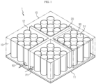
- FIG. 1 is a perspective view of a battery pack according to an embodiment of the present disclosure
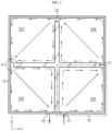
- FIG. 2 is a plan view of the battery pack according to an embodiment of the present disclosure.
- the battery pack 1 includes a pack case 10, a cross beam 20 and a battery module 30.
- the battery pack 1 may be used in, for example, an electric vehicle 2.
- the pack case 10 includes a bottom cover 11, a top cover 12 and a side cover 13.
- the pack case 10 includes a coolant feed port P1 and a coolant exit port P2 serving as passages through which a dielectric coolant enters and exits, respectively. Additionally, the pack case 10 accommodates the cross beam 20 and the battery module 30.
- the pack case 10 may protect a plurality of battery modules 30 from external impacts, and accordingly, its material is preferably a soft material, but is not limited thereto.
- the pack case 10 is indicated by the dash-dotted line.
- the side cover 13 may have the coolant feed port P1 and the coolant exit port P2, through which the dielectric coolant enters and exits.
- the coolant feed port P1 and the coolant exit port P2 may be in the bottom cover 11 or the top cover 12. Since the dielectric coolant passes through the pack case 10, the pack case 10 may be hermetically sealed up except the coolant feed port P1 and the coolant exit port P2. Accordingly, the dielectric coolant entering through the coolant feed port P1 does not leak out of the pack case 10.
- the dielectric coolant entering through the coolant feed port P1 of the pack case 10 may pass through all the battery modules 30 included in the battery pack 1 in a sequential order and exit the coolant exit port P2.
- the dielectric coolant may be used to cool down through direct contact with all the battery cells 31 included in the battery pack 1, thereby improving the cooling efficiency.
- the coolant may be a liquid having high insulation performance, for example, a dielectric coolant fluid, but is not limited thereto.
- FIG. 2 is a plan view of the battery pack according to an embodiment of the present disclosure
- FIG. 3 is a plan view of a battery pack according to another embodiment of the present disclosure
- FIG. 4 is a perspective view and a cross-sectional view of a battery pack according to still another embodiment of the present disclosure.
- the cross beam 20 may include at least one horizontal beam 21 and at least one vertical beam 22.
- the horizontal beam 21 and the vertical beam 22 may be approximately perpendicular to each other.
- FIG. 2 shows the cross beam 20 of a criss-cross pattern including one horizontal beam 21 and one vertical beam 22 crossing each other
- FIG. 3 shows the cross beam 20 including two horizontal beams 211, 212 and one vertical beam 22 crossing each other.
- the internal space of the pack case 10 may be divided into four spaces.
- the internal space of the pack case 10 may be divided into six spaces.
- the internal space of the pack case 10 may be divided into multiple spaces by at least one horizontal beam 21 and one vertical beam 22, and the battery module 30 may be positioned in each divided space.
- the cross beam 20 may include a plurality of vertical beams 22.
- the cross beam 20 may include at least three horizontal beams and at least two vertical beams.
- the internal space of the pack case 10 may be divided into eight or more spaces.
- the pack case 10 may have a coolant passage through which the dielectric coolant passes from one battery module accommodation space to its adjacent battery module accommodation space. That is, the cross beam 20 may have a space through which the dielectric coolant passes.
- the structure in which the cross beam 20 is spaced the predetermined distance apart from the side cover 13 of the pack case 10 will be described.
- two ends of the horizontal beam 21 in the lengthwise direction are spaced the predetermined distance apart from the side cover 13 of the pack case 10.
- One end of the vertical beam 22 in the lengthwise direction is spaced the predetermined distance apart from the side cover 13 of the pack case 10.
- the dielectric coolant may pass through a gap G between the cross beam 20 and the side cover 13.
- the arrow indicates the schematic flow of the dielectric coolant.
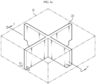
- FIG. 4a is a perspective view of a battery pack according to still another embodiment of the present disclosure
- FIG. 4b is a cross-sectional view of FIG. 4a taken along the line A-A' when viewed in a direction perpendicular to the cross section
- FIG. 4c is a cross-sectional view showing another embodiment of FIG. 4b .
- the cross beam 20 contacts the side cover 13 of the pack case 10 without a gap.
- the cross beam 20 has the opening through which the dielectric coolant enters and exits.
- the shape of the opening may be a notch shape Hi.
- the shape of the opening may be a hole shape H 2 .
- the shape of the opening is not limited thereto, and may include any shape that allows the dielectric coolant to enter and exit.
- the battery pack 1 since the cross beam 20 contacts the side cover 13 of the pack case 10 without a gap, the battery pack 1 may be adequately supported by the cross beam 20, and accordingly, it is possible to effectively protect the battery cells 31 in the battery pack 1 when external impacts occur, for example, due to vehicle accidents.
- the embodiment of the present disclosure is not limited to the structure in which the cross beam 20 is spaced the predetermined distance apart from the side cover 13 of the pack case 10 (see FIG. 2 ), or the structure in which the cross beam 20 has the opening (see FIGS. 4a to 4c ), and each embodiment may be applied in combination.
- the structure in which the cross beam 20 is spaced the predetermined distance apart from the side cover 13 of the pack case 10 may be applied to the horizontal beam, and the structure in which the cross beam 20 has the opening may be applied to the vertical beam, and vice versa.
- FIG. 5 is an enlarged plan view of the dash-dotted line section in FIG. 2
- FIG. 6 is a plan view showing another embodiment of FIG. 5 .
- the battery module 30 is defined as an assembly of battery cells 31, and the battery module 30 does not need to include a physical battery module case.
- the battery module 30 may include the battery module case.
- the battery module 30 includes the plurality of battery cells 31.
- the dash-dotted line section corresponds to one battery module 30.
- the battery module 30 may have a plurality of corners 301, 302, 303, 304.
- FIG. 6 shows the battery module 30 of approximately a square shape in plan view, having four corners 301, 302, 303, 304 accordingly.
- the shape of the battery module 30 of the present disclosure is not limited thereto.
- the battery module 30 may not include the physical battery module case.
- the battery module 30 refers to an assembly of battery cells 31, to be specific, an assembly of battery cells 31 disposed in the internal space of the pack case 10 divided by the cross beam 20.
- the battery module 30 includes an inlet and an outlet through which the dielectric coolant fed into the pack case 10 enters and exits.
- the inlet and the outlet may refer to a pipe and/or a hole that acts as a passage of the dielectric coolant, but may be the name introduced for convenience of description in describing the flow of the dielectric coolant in the battery module 30.
- the module case (not shown) accommodating the plurality of battery cells 31, the module case has a passage through which the dielectric coolant actually enters and exits for direct contact of the dielectric coolant with the battery cells 31.
- the inlet and the outlet may refer to a physical element that acts as a passage, for example, a pipe and/or a hole.
- the inlet and the outlet may refer to an area where the dielectric coolant enters and exits, rather than a real physical element.
- a physical element for example, a guide plate or a pipe may be applied to guide the flow of the dielectric coolant at the area where the dielectric coolant enters and exits in the battery module 30. Accordingly, in this case, despite the absence of the module case, the inlet and the outlet may refer to a physical element.
- the plurality of spaces divided by the cross beam 20 may be in communication with each other by the gap G formed by the spacing between the cross beam 20 and the side cover 13 or the opening of the notch or hole shape in the cross beam 20. That is, the outlet of the battery module 30 on one side and the inlet of the battery module 30 on the other side with the horizontal beam 21 or the vertical beam 22 interposed between them are positioned in the cross beam 20 itself or at a location corresponding to the coolant passage between the cross beam 20 and the side cover 13.
- Each of the inlet and the outlet of the battery module 30 may be disposed in any one of the plurality of corners 301, 302, 303, 304.
- the inlet may be disposed at the bottom left corner 301 and the outlet may be disposed at the top right corner 302, to allow the dielectric coolant entering through the inlet to pass through the battery module 30 and exit the outlet.
- the battery module 30 may have a structure in which the dielectric coolant entering through the inlet on one side of the battery module 30 exits the outlet opposite the inlet across the battery module 30.
- the battery module 30 may have a structure in which the dielectric coolant enters through the inlet at the bottom left corner 301 of FIG. 5 , and exits the outlet at the corner 302 opposite the inlet across the battery module 30.
- the dielectric coolant exiting the outlet of the specific battery module 30 may enter the inlet of the adjacent battery module 30.
- the dielectric coolant entering through the coolant feed port P1 of the pack case 10 may pass through all the battery modules 30 included in the battery pack 1 in a sequential order and exit the coolant exit port P2.
- the dielectric coolant entering the first battery module 30A through the coolant feed port P1 moves from the inlet of the first battery module 30A to the outlet and enters the second battery module 30B through the coolant passage.
- the dielectric coolant entering through the inlet of the second battery module 30B enters the third battery module 30C through the outlet of the second battery module 30B and the coolant passage.
- the dielectric coolant entering through the inlet of the third battery module 30C enters the fourth battery module 30D through the outlet of the third battery module 30C and the coolant passage.
- the dielectric coolant entering through the inlet of the fourth battery module 30D exits the battery pack 1 through the outlet of the fourth battery module 30D and the coolant exit port P2.
- the fed dielectric coolant may exit after cooling all the battery modules 30, and as a result, it is possible to achieve maximum cooling efficiency by the direct contact of the dielectric coolant with all the battery cells 31.
- the battery cell 31 is shown as a cylindrical cell in the embodiment of FIG. 1 , the battery cell 31 is not limited thereto, and may be a prismatic cell or a pouch-type cell.
- the plurality of battery cells 31 is positioned in the spaces divided by the cross beam 20. All the battery cells 31 included in the battery module 30 may directly contact the dielectric coolant.
- the direct contact structure of each battery cell 31 with the dielectric coolant eliminates the need for a heat absorption source (a heat sink) that occupies an extra space, thereby reducing the manufacturing cost of the battery pack 1, and further, contributing to the reduced size of the battery pack 1. Additionally, it is possible to increase the cooling area by the direct contact structure of the present disclosure between the dielectric coolant and the lower surface, the lateral peripheral surface and even the upper surface of the battery cells 31, thereby maximizing the cooling efficiency of the battery pack 1.
- the plurality of battery cells 31 included in the battery module 30 may be arranged at a predetermined interval.
- the battery cells 31 may be arranged in a checkerboard pattern.
- the battery cells 31 are arranged at the predetermined interval, it is possible to achieve the structural simplicity, thereby increasing the convenience in manufacturing the battery pack 1.
- the plurality of battery cells 31 included in the battery module 30 may be arranged with the arrangement density that gradually increases or decreases as it goes in a specific direction. That is, the arrangement pattern of the plurality of battery cells 31 may be a gradation pattern.
- the arrangement density of the battery cells 31 included in the battery module 30 may be lower at a distance farther away from the shortest path S among the paths from the inlet to the outlet. More specifically, the battery cells 31 may be arranged with higher density at the shortest path S from the inlet to the outlet to allow the dielectric coolant to flow less smoothly than the other paths, and the battery cells 31 may be arranged with lower density at the distance farther away from the shortest path S to prevent the dielectric coolant from flowing intensively through the shortest path S.
- the dielectric coolant may not smoothly flow in to the corners 303, 304 at which the inlet and the outlet are not disposed among the corners 301, 302, 303, 304 of the battery module 30, and in the present disclosure, the battery cells 31 are arranged with lowest density at the corners 303, 304 as shown in FIG. 6 , to allow the dielectric coolant to smoothly flow in to the corners 303, 304 at which the inlet and the outlet are not disposed.
- the present disclosure may effectively cool down even the battery cells 31 near the corners 303, 304 at which the inlet and the outlet are not disposed, thereby uniformly improving the cooling efficiency of the entire battery module 30.
- FIG. 7 is a perspective view showing the vehicle 2 including the battery pack 1 of the present disclosure.
- the vehicle 2 according to the present disclosure may include the battery pack 1 according to the present disclosure.
Landscapes
- Chemical & Material Sciences (AREA)
- Chemical Kinetics & Catalysis (AREA)
- Electrochemistry (AREA)
- General Chemical & Material Sciences (AREA)
- Engineering & Computer Science (AREA)
- Manufacturing & Machinery (AREA)
- Aviation & Aerospace Engineering (AREA)
- Secondary Cells (AREA)
- Battery Mounting, Suspending (AREA)
Abstract
Description
- The present disclosure relates to a battery pack and a vehicle comprising the same, and more particularly, to a battery pack for effectively increasing the cooling efficiency of battery cells and a vehicle comprising the same.
- The present application claims the benefit of
Korean Patent Application No. 10-2021-0058807 filed on May 6, 2021 - Recently, with the development of mobile devices, rechargeable secondary batteries are used in a wide range of applications. Additionally, secondary batteries are gaining attention as a power source of electric vehicles suggested as an alternative to the existing gasoline vehicles and diesel vehicles using fossil fuel in an attempt to solve the air pollution problem.
- In the case of devices requiring a large amount of electricity such as electric vehicles, in general, a battery pack includes a plurality of battery modules, and to increase the energy density, in many cases, the plurality of battery modules are densely arranged in a very narrow space.
- However, a large amount of heat is generated during the charge/discharge of high capacity secondary batteries, and in case that the heat generated during the charge/discharge is not effectively removed, heat accumulation occurs, which accelerates the degradation of the batteries, and in some cases, there are fire or explosion risks.
- Accordingly, there is a need for the development of a cooling system to efficiently cool battery cells embedded in an automobile battery pack with high capacity.
- The present disclosure is designed to solve the above-described problem, and therefore the present disclosure is directed to providing a battery pack with improved cooling efficiency of battery cells by direct cooling of the battery cells through a dielectric coolant and a vehicle comprising the same.
- The present disclosure is further directed to providing a battery pack with the reduced manufacturing cost and size.
- However, the technical problem of the present disclosure to be solved is not limited to the above-described problems, and these and other problems will be clearly understood by those skilled in the art from the following detailed description.
- To achieve the above-described objective, a battery pack of the present disclosure includes a pack case including a coolant feed port and a coolant exit port through which a dielectric coolant enters and exits; a cross beam positioned in the pack case and having a space through which the dielectric coolant passes; and a plurality of battery modules, each including a plurality of battery cells, each battery module positioned in each space divided by the cross beam.
- In this instance, the pack case may be hermetically sealed up except the coolant feed port and the coolant exit port.
- Here, the plurality of battery cells included in the each battery module directly contacts the dielectric coolant.
- In particular, the dielectric coolant may enter through an inlet on one side of the each battery module, and exit an outlet opposite the inlet across the each battery module.
- In this instance, the each battery module may include a plurality of corners, and each of the inlet and the outlet of the each battery module may be disposed at any one of the plurality of corners.
- Additionally, the dielectric coolant exiting the outlet of one battery module of the plurality of battery modules may enter through the inlet of another battery module adjacent to the one battery module.
- In this instance, the dielectric coolant entering through the coolant feed port of the pack case may pass through all the battery modules included in the battery pack in a sequential order, and exit the coolant exit port.
- In this instance, the plurality of battery cells included in the each battery module may be arranged at a predetermined interval.
- Alternatively, an arrangement density of the plurality of battery cells included in the each battery module may gradually increase or decrease in a specific direction.
- In particular, an arrangement density of the battery cells included in the each battery module may be lower at a distance farther away from a shortest path among paths from the inlet to the outlet.
- In this instance, the cross beam may be spaced a predetermined distance apart from a side cover of the pack case.
- Alternatively, the cross beam may contact a side cover of the pack case, and at least part of the cross beam may have an opening through which the dielectric coolant enters and exits.
- A vehicle according to an embodiment of the present disclosure includes the battery pack according to an embodiment of the present disclosure.
- According to the present disclosure, it is possible to efficiently cool the battery pack by the direct contact structure between the dielectric coolant and each battery cell and the specific placement structure of the cross beam and/or the battery cells in the battery pack.
- In addition, according to the present disclosure, it is possible to reduce the size and manufacturing cost of the battery pack.
- The accompanying drawings illustrate the exemplary embodiment of the present disclosure, and together with the following detailed description, serve to provide a further understanding of the technical aspects of the present disclosure, and thus the present disclosure should not be construed as being limited to the drawings.
-
FIG. 1 is a perspective view of a battery pack according to an embodiment of the present disclosure. -
FIG. 2 is a plan view of a battery pack according to an embodiment of the present disclosure. -
FIG. 3 is a plan view of a battery pack according to another embodiment of the present disclosure. -
FIG. 4a is a perspective view of a battery pack according to still another embodiment of the present disclosure. -
FIG. 4b is a cross-sectional view ofFIG. 4a taken along the line A-A' when viewed in a direction perpendicular to the cross section. -
FIG. 4c is a cross-sectional view showing another embodiment ofFIG. 4b . -
FIG. 5 is an enlarged plan view of a dash-dotted line section inFIG. 2 . -
FIG. 6 is a plan view showing another embodiment ofFIG. 5 . -
FIG. 7 is a perspective view showing a vehicle including a battery pack of the present disclosure. - Hereinafter, the exemplary embodiment of the present disclosure will be described in detail with reference to the accompanying drawings. Prior to the description, it should be understood that the terms or words used in the specification and the appended claims should not be construed as being limited to general and dictionary meanings, but rather interpreted based on the meanings and concepts corresponding to the technical aspects of the present disclosure on the basis of the principle that the inventor is allowed to define the terms appropriately for the best explanation.
- Therefore, the embodiments described herein and the illustrations shown in the drawings are just an exemplary embodiment of the present disclosure, but not intended to fully describe the technical aspects of the present disclosure, so it should be understood that a variety of other equivalents and modifications could have been made thereto at the time that the application was filed.
-
FIG. 1 is a perspective view of a battery pack according to an embodiment of the present disclosure, andFIG. 2 is a plan view of the battery pack according to an embodiment of the present disclosure. - Referring to
FIGS. 1 and2 , the battery pack 1 according to the present disclosure includes apack case 10, across beam 20 and abattery module 30. The battery pack 1 may be used in, for example, an electric vehicle 2. - To begin with, the
pack case 10 will be described. - Referring to
FIG. 1 , thepack case 10 includes abottom cover 11, atop cover 12 and aside cover 13. Thepack case 10 includes a coolant feed port P1 and a coolant exit port P2 serving as passages through which a dielectric coolant enters and exits, respectively. Additionally, thepack case 10 accommodates thecross beam 20 and thebattery module 30. Thepack case 10 may protect a plurality ofbattery modules 30 from external impacts, and accordingly, its material is preferably a soft material, but is not limited thereto. For convenience of description of the internal structure of thepack case 10, thepack case 10 is indicated by the dash-dotted line. - The
side cover 13 may have the coolant feed port P1 and the coolant exit port P2, through which the dielectric coolant enters and exits. Alternatively, the coolant feed port P1 and the coolant exit port P2 may be in thebottom cover 11 or thetop cover 12. Since the dielectric coolant passes through thepack case 10, thepack case 10 may be hermetically sealed up except the coolant feed port P1 and the coolant exit port P2. Accordingly, the dielectric coolant entering through the coolant feed port P1 does not leak out of thepack case 10. The dielectric coolant entering through the coolant feed port P1 of thepack case 10 may pass through all thebattery modules 30 included in the battery pack 1 in a sequential order and exit the coolant exit port P2. - Accordingly, the dielectric coolant may be used to cool down through direct contact with all the
battery cells 31 included in the battery pack 1, thereby improving the cooling efficiency. - The coolant may be a liquid having high insulation performance, for example, a dielectric coolant fluid, but is not limited thereto.
- Subsequently, the
cross beam 20 will be described. -
FIG. 2 is a plan view of the battery pack according to an embodiment of the present disclosure,FIG. 3 is a plan view of a battery pack according to another embodiment of the present disclosure, andFIG. 4 is a perspective view and a cross-sectional view of a battery pack according to still another embodiment of the present disclosure. - Referring to
FIGS. 2 to 4 , thecross beam 20 may include at least onehorizontal beam 21 and at least onevertical beam 22. Thehorizontal beam 21 and thevertical beam 22 may be approximately perpendicular to each other. Specifically,FIG. 2 shows thecross beam 20 of a criss-cross pattern including onehorizontal beam 21 and onevertical beam 22 crossing each other, andFIG. 3 shows thecross beam 20 including twohorizontal beams vertical beam 22 crossing each other. - As shown in
FIG. 2 , when thecross beam 20 includes onehorizontal beam 21 and onevertical beam 22 approximately perpendicular to each other, the internal space of thepack case 10 may be divided into four spaces. - Alternatively, as shown in
FIG. 3 , when thecross beam 20 includes twohorizontal beams vertical beam 22 approximately perpendicular to each other, the internal space of thepack case 10 may be divided into six spaces. As described above, the internal space of thepack case 10 may be divided into multiple spaces by at least onehorizontal beam 21 and onevertical beam 22, and thebattery module 30 may be positioned in each divided space. For reference, although not shown, thecross beam 20 may include a plurality ofvertical beams 22. - Although the drawings of the present disclosure show that the internal space of the
pack case 10 is divided into four (seeFIG. 2 ) and six (seeFIG. 3 ), the present disclosure is not limited thereto. Thecross beam 20 may include at least three horizontal beams and at least two vertical beams. In this case, the internal space of thepack case 10 may be divided into eight or more spaces. - By a structure in which the
cross beam 20 is spaced a predetermined distance apart from theside cover 13 of thepack case 10 or a structure in which thecross beam 20 has an opening, thepack case 10 may have a coolant passage through which the dielectric coolant passes from one battery module accommodation space to its adjacent battery module accommodation space. That is, thecross beam 20 may have a space through which the dielectric coolant passes. - To begin with, the structure in which the
cross beam 20 is spaced the predetermined distance apart from theside cover 13 of thepack case 10 will be described. Referring toFIG. 2 , two ends of thehorizontal beam 21 in the lengthwise direction (parallel to the X axis) are spaced the predetermined distance apart from theside cover 13 of thepack case 10. One end of thevertical beam 22 in the lengthwise direction (parallel to the Y axis) is spaced the predetermined distance apart from theside cover 13 of thepack case 10. Accordingly, the dielectric coolant may pass through a gap G between thecross beam 20 and theside cover 13. InFIG. 2 , the arrow indicates the schematic flow of the dielectric coolant. - As described above, since there is the gap G between the
cross beam 20 and theside cover 13 of thepack case 10, with a simple structure such as thecross beam 20, it is possible to efficiently guide the flow of the dielectric coolant in the battery pack 1. Additionally, according to the above-described structure, with a simple structure such as thecross beam 20, it is possible to allow the dielectric coolant to pass through the entire area of the battery pack 1, thereby increasing the cooling efficiency. - Subsequently, the structure in which the
cross beam 20 has the opening will be described.FIG. 4a is a perspective view of a battery pack according to still another embodiment of the present disclosure,FIG. 4b is a cross-sectional view ofFIG. 4a taken along the line A-A' when viewed in a direction perpendicular to the cross section, andFIG. 4c is a cross-sectional view showing another embodiment ofFIG. 4b . - Referring to
FIGS. 4a to 4c , thecross beam 20 contacts theside cover 13 of thepack case 10 without a gap. - Referring to
FIG. 4b , at least part of thecross beam 20 has the opening through which the dielectric coolant enters and exits. The shape of the opening may be a notch shape Hi. Referring toFIG. 4c of still another embodiment, the shape of the opening may be a hole shape H2. However, the shape of the opening is not limited thereto, and may include any shape that allows the dielectric coolant to enter and exit. - According to this embodiment, since the
cross beam 20 contacts theside cover 13 of thepack case 10 without a gap, the battery pack 1 may be adequately supported by thecross beam 20, and accordingly, it is possible to effectively protect thebattery cells 31 in the battery pack 1 when external impacts occur, for example, due to vehicle accidents. - The embodiment of the present disclosure is not limited to the structure in which the
cross beam 20 is spaced the predetermined distance apart from theside cover 13 of the pack case 10 (seeFIG. 2 ), or the structure in which thecross beam 20 has the opening (seeFIGS. 4a to 4c ), and each embodiment may be applied in combination. For example, the structure in which thecross beam 20 is spaced the predetermined distance apart from theside cover 13 of thepack case 10 may be applied to the horizontal beam, and the structure in which thecross beam 20 has the opening may be applied to the vertical beam, and vice versa. - Subsequently, the
battery module 30 will be described. -
FIG. 5 is an enlarged plan view of the dash-dotted line section inFIG. 2 , andFIG. 6 is a plan view showing another embodiment ofFIG. 5 . - Here, the
battery module 30 is defined as an assembly ofbattery cells 31, and thebattery module 30 does not need to include a physical battery module case. However, in another embodiment of the present disclosure, thebattery module 30 may include the battery module case. - Referring to
FIGS. 1 ,2 ,5 and6 , thebattery module 30 according to the present disclosure includes the plurality ofbattery cells 31. - In
FIG. 2 , the dash-dotted line section corresponds to onebattery module 30. Referring toFIG. 6 , thebattery module 30 may have a plurality ofcorners FIG. 6 shows thebattery module 30 of approximately a square shape in plan view, having fourcorners battery module 30 of the present disclosure is not limited thereto. - Meanwhile, referring to
FIG. 1 , thebattery module 30 according to an embodiment of the present disclosure may not include the physical battery module case. In an embodiment of the present disclosure, thebattery module 30 refers to an assembly ofbattery cells 31, to be specific, an assembly ofbattery cells 31 disposed in the internal space of thepack case 10 divided by thecross beam 20. - The
battery module 30 includes an inlet and an outlet through which the dielectric coolant fed into thepack case 10 enters and exits. The inlet and the outlet may refer to a pipe and/or a hole that acts as a passage of the dielectric coolant, but may be the name introduced for convenience of description in describing the flow of the dielectric coolant in thebattery module 30. - When the
battery module 30 includes the module case (not shown) accommodating the plurality ofbattery cells 31, the module case has a passage through which the dielectric coolant actually enters and exits for direct contact of the dielectric coolant with thebattery cells 31. Accordingly, in this case, the inlet and the outlet may refer to a physical element that acts as a passage, for example, a pipe and/or a hole. - Alternatively, in case that the
battery module 30 does not include the module case, and accordingly, the plurality ofbattery cells 31 is positioned on thebottom cover 11 of thepack case 10, the inlet and the outlet may refer to an area where the dielectric coolant enters and exits, rather than a real physical element. Even in case that thebattery module 30 does not include the module case, a physical element, for example, a guide plate or a pipe may be applied to guide the flow of the dielectric coolant at the area where the dielectric coolant enters and exits in thebattery module 30. Accordingly, in this case, despite the absence of the module case, the inlet and the outlet may refer to a physical element. - Referring to
FIGS. 2 to 4c , the plurality of spaces divided by thecross beam 20 may be in communication with each other by the gap G formed by the spacing between thecross beam 20 and theside cover 13 or the opening of the notch or hole shape in thecross beam 20. That is, the outlet of thebattery module 30 on one side and the inlet of thebattery module 30 on the other side with thehorizontal beam 21 or thevertical beam 22 interposed between them are positioned in thecross beam 20 itself or at a location corresponding to the coolant passage between thecross beam 20 and theside cover 13. - Each of the inlet and the outlet of the
battery module 30 may be disposed in any one of the plurality ofcorners battery module 30 ofFIG. 5 , the inlet may be disposed at the bottomleft corner 301 and the outlet may be disposed at the topright corner 302, to allow the dielectric coolant entering through the inlet to pass through thebattery module 30 and exit the outlet. - The
battery module 30 according to an embodiment of the present disclosure may have a structure in which the dielectric coolant entering through the inlet on one side of thebattery module 30 exits the outlet opposite the inlet across thebattery module 30. For example, thebattery module 30 may have a structure in which the dielectric coolant enters through the inlet at the bottomleft corner 301 ofFIG. 5 , and exits the outlet at thecorner 302 opposite the inlet across thebattery module 30. - Referring to
FIGS. 2 and3 , the dielectric coolant exiting the outlet of thespecific battery module 30 may enter the inlet of theadjacent battery module 30. In particular, the dielectric coolant entering through the coolant feed port P1 of thepack case 10 may pass through all thebattery modules 30 included in the battery pack 1 in a sequential order and exit the coolant exit port P2. - Describing the flow of the dielectric coolant with reference to
FIG. 2 by way of illustration, the dielectric coolant entering thefirst battery module 30A through the coolant feed port P1 moves from the inlet of thefirst battery module 30A to the outlet and enters thesecond battery module 30B through the coolant passage. The dielectric coolant entering through the inlet of thesecond battery module 30B enters thethird battery module 30C through the outlet of thesecond battery module 30B and the coolant passage. The dielectric coolant entering through the inlet of thethird battery module 30C enters thefourth battery module 30D through the outlet of thethird battery module 30C and the coolant passage. The dielectric coolant entering through the inlet of thefourth battery module 30D exits the battery pack 1 through the outlet of thefourth battery module 30D and the coolant exit port P2. - Accordingly, the fed dielectric coolant may exit after cooling all the
battery modules 30, and as a result, it is possible to achieve maximum cooling efficiency by the direct contact of the dielectric coolant with all thebattery cells 31. - Although the
battery cell 31 is shown as a cylindrical cell in the embodiment ofFIG. 1 , thebattery cell 31 is not limited thereto, and may be a prismatic cell or a pouch-type cell. - The plurality of
battery cells 31 is positioned in the spaces divided by thecross beam 20. All thebattery cells 31 included in thebattery module 30 may directly contact the dielectric coolant. - Accordingly, it is possible to maximize the contact area between the dielectric coolant and each
battery cell 31, thereby improving the overall cooling efficiency of the battery pack 1. Furthermore, the direct contact structure of eachbattery cell 31 with the dielectric coolant according to the present disclosure eliminates the need for a heat absorption source (a heat sink) that occupies an extra space, thereby reducing the manufacturing cost of the battery pack 1, and further, contributing to the reduced size of the battery pack 1. Additionally, it is possible to increase the cooling area by the direct contact structure of the present disclosure between the dielectric coolant and the lower surface, the lateral peripheral surface and even the upper surface of thebattery cells 31, thereby maximizing the cooling efficiency of the battery pack 1. - As shown in
FIG. 5 , the plurality ofbattery cells 31 included in thebattery module 30 according to an embodiment of the present disclosure may be arranged at a predetermined interval. For example, thebattery cells 31 may be arranged in a checkerboard pattern. - According to this embodiment, since the
battery cells 31 are arranged at the predetermined interval, it is possible to achieve the structural simplicity, thereby increasing the convenience in manufacturing the battery pack 1. - In another embodiment of the present disclosure, referring to
FIG. 6 , the plurality ofbattery cells 31 included in thebattery module 30 may be arranged with the arrangement density that gradually increases or decreases as it goes in a specific direction. That is, the arrangement pattern of the plurality ofbattery cells 31 may be a gradation pattern. - For example, as shown in
FIG. 6 , the arrangement density of thebattery cells 31 included in thebattery module 30 may be lower at a distance farther away from the shortest path S among the paths from the inlet to the outlet. More specifically, thebattery cells 31 may be arranged with higher density at the shortest path S from the inlet to the outlet to allow the dielectric coolant to flow less smoothly than the other paths, and thebattery cells 31 may be arranged with lower density at the distance farther away from the shortest path S to prevent the dielectric coolant from flowing intensively through the shortest path S. In particular, due to the physical structure, the dielectric coolant may not smoothly flow in to thecorners corners battery module 30, and in the present disclosure, thebattery cells 31 are arranged with lowest density at thecorners FIG. 6 , to allow the dielectric coolant to smoothly flow in to thecorners - By this structure, the present disclosure may effectively cool down even the
battery cells 31 near thecorners entire battery module 30. -
FIG. 7 is a perspective view showing the vehicle 2 including the battery pack 1 of the present disclosure. - Referring to
FIG. 7 , the vehicle 2 according to the present disclosure may include the battery pack 1 according to the present disclosure. - It should be noted that the terms indicating directions as used herein such as upper and lower are used for convenience of description only, and it is obvious to those skilled in the art that the term may change depending on the position of the stated element or an observer.
- While the present disclosure has been hereinabove described with regard to a limited number of embodiments and drawings, the present disclosure is not limited thereto and it is obvious to those skilled in the art that various modifications and changes may be made within the technical aspects of the present disclosure and the scope of the appended claims and equivalents thereof.
Claims (13)
- A battery pack, comprising:a pack case including a coolant feed port and a coolant exit port through which a dielectric coolant enters and exits;a cross beam positioned in the pack case and having a space through which the dielectric coolant passes; anda plurality of battery modules, each including a plurality of battery cells, each battery module positioned in each space divided by the cross beam.
- The battery pack according to claim 1, wherein the pack case is hermetically sealed up except the coolant feed port and the coolant exit port.
- The battery pack according to claim 1, wherein the plurality of battery cells included in the each battery module directly contacts the dielectric coolant.
- The battery pack according to claim 1, wherein the dielectric coolant enters through an inlet on one side of the each battery module, and exits an outlet opposite the inlet across the each battery module.
- The battery pack according to claim 4, wherein the each battery module includes a plurality of corners, and
wherein each of the inlet and the outlet of the each battery module is disposed at any one of the plurality of corners. - The battery pack according to claim 4, wherein the dielectric coolant exiting the outlet of one battery module of the plurality of battery modules enters through the inlet of another battery module adjacent to the one battery module.
- The battery pack according to claim 4, wherein the dielectric coolant entering through the coolant feed port of the pack case passes through all the battery modules included in the battery pack in a sequential order, and exits the coolant exit port.
- The battery pack according to claim 1, wherein the plurality of battery cells included in the each battery module is arranged at a predetermined interval.
- The battery pack according to claim 1, wherein an arrangement density of the plurality of battery cells included in the each battery module gradually increases or decreases in a specific direction.
- The battery pack according to claim 4, wherein an arrangement density of the battery cells included in the each battery module is lower at a distance farther away from a shortest path among paths from the inlet to the outlet.
- The battery pack according to claim 1, wherein the cross beam is spaced a predetermined distance apart from a side cover of the pack case.
- The battery pack according to claim 1, wherein the cross beam contacts a side cover of the pack case, and
wherein at least part of the cross beam has an opening through which the dielectric coolant enters and exits. - A vehicle comprising the battery pack defined in any one of claims 1 to 12.
Applications Claiming Priority (2)
| Application Number | Priority Date | Filing Date | Title |
|---|---|---|---|
| KR1020210058807A KR20220151493A (en) | 2021-05-06 | 2021-05-06 | Battery pack with improved Cooling performance and Vehicle comprising the same |
| PCT/KR2022/005523 WO2022234975A1 (en) | 2021-05-06 | 2022-04-18 | Battery pack having improved cooling performance and vehicle including same |
Publications (2)
| Publication Number | Publication Date |
|---|---|
| EP4270604A1 true EP4270604A1 (en) | 2023-11-01 |
| EP4270604A4 EP4270604A4 (en) | 2024-12-04 |
Family
ID=83932366
Family Applications (1)
| Application Number | Title | Priority Date | Filing Date |
|---|---|---|---|
| EP22799020.7A Pending EP4270604A4 (en) | 2021-05-06 | 2022-04-18 | Battery pack having improved cooling performance and vehicle including same |
Country Status (6)
| Country | Link |
|---|---|
| US (1) | US20250055070A1 (en) |
| EP (1) | EP4270604A4 (en) |
| JP (1) | JP7608615B2 (en) |
| KR (1) | KR20220151493A (en) |
| CN (1) | CN116783760A (en) |
| WO (1) | WO2022234975A1 (en) |
Family Cites Families (14)
| Publication number | Priority date | Publication date | Assignee | Title |
|---|---|---|---|---|
| JPH09266016A (en) * | 1996-03-27 | 1997-10-07 | Toyota Autom Loom Works Ltd | Method for cooling cylindrical battery |
| JPH11329518A (en) * | 1998-05-21 | 1999-11-30 | Toshiba Battery Co Ltd | Battery device |
| JP2003346924A (en) * | 2002-05-29 | 2003-12-05 | Fuji Heavy Ind Ltd | Battery cooling system and battery cooling method |
| JP4062273B2 (en) * | 2004-03-31 | 2008-03-19 | 日産自動車株式会社 | Assembled battery |
| US9306224B2 (en) * | 2010-09-02 | 2016-04-05 | Akasol Engineering Gmbh | Cooling module and method for producing a cooling module |
| JP2013004468A (en) * | 2011-06-21 | 2013-01-07 | Sharp Corp | Battery pack device |
| JP2016122543A (en) * | 2014-12-24 | 2016-07-07 | トヨタ自動車株式会社 | Battery cooling device |
| KR102061745B1 (en) * | 2016-04-25 | 2020-01-02 | 주식회사 엘지화학 | Battery pack and vehicle comprising the battery pack |
| CN106602171B (en) * | 2016-12-22 | 2019-04-26 | 中国矿业大学 | A phase change material/air coupled hierarchical battery thermal management system |
| KR102256098B1 (en) * | 2017-04-06 | 2021-06-03 | 주식회사 엘지에너지솔루션 | Battery Pack having heat conductive medium of louver fin form |
| JP6269889B1 (en) * | 2017-07-27 | 2018-01-31 | トヨタ自動車株式会社 | Battery cooling system |
| DE102018212627A1 (en) * | 2018-07-27 | 2020-01-30 | Mahle International Gmbh | accumulator |
| CN112740001B (en) | 2018-09-20 | 2023-03-21 | 日写株式会社 | Capacitance detection device capable of calculating shearing force |
| KR102828349B1 (en) * | 2019-09-09 | 2025-07-03 | 삼성에스디아이 주식회사 | Battery pack |
-
2021
- 2021-05-06 KR KR1020210058807A patent/KR20220151493A/en active Pending
-
2022
- 2022-04-18 US US18/289,251 patent/US20250055070A1/en active Pending
- 2022-04-18 EP EP22799020.7A patent/EP4270604A4/en active Pending
- 2022-04-18 JP JP2023537692A patent/JP7608615B2/en active Active
- 2022-04-18 CN CN202280008322.3A patent/CN116783760A/en active Pending
- 2022-04-18 WO PCT/KR2022/005523 patent/WO2022234975A1/en not_active Ceased
Also Published As
| Publication number | Publication date |
|---|---|
| KR20220151493A (en) | 2022-11-15 |
| WO2022234975A1 (en) | 2022-11-10 |
| CN116783760A (en) | 2023-09-19 |
| JP2024500861A (en) | 2024-01-10 |
| US20250055070A1 (en) | 2025-02-13 |
| EP4270604A4 (en) | 2024-12-04 |
| JP7608615B2 (en) | 2025-01-06 |
Similar Documents
| Publication | Publication Date | Title |
|---|---|---|
| KR102276261B1 (en) | Battery sub-module carrier, battery sub-module, battery system and automobile | |
| CN102484297B (en) | Battery pack with cooling structure | |
| US20070026303A1 (en) | Battery module | |
| KR20200044580A (en) | Large module of battery | |
| CN102473981A (en) | Electrical storage module | |
| EP2557612A1 (en) | Battery module | |
| CN116325298B (en) | Battery, electric device, method and equipment for preparing battery | |
| KR100696669B1 (en) | Secondary battery module | |
| KR20200044581A (en) | Large module of battery | |
| US20240421435A1 (en) | Battery cell, battery module, battery, and electric apparatus | |
| US20240222759A1 (en) | Battery cell, battery, electric device, and method and device for manufacturing battery | |
| US20240204290A1 (en) | Battery assembly and battery pack including battery assembly | |
| US12494549B2 (en) | Battery module and battery pack comprising same | |
| CN116615830B (en) | Battery, electric device, method and equipment for preparing battery | |
| US20250055070A1 (en) | Battery Pack with Improved Cooling Performance and Vehicle Comprising the Same | |
| CN221614019U (en) | Batteries and electrical equipment | |
| JP7826564B2 (en) | Double-sided cooling battery module and heat sink included therein | |
| US20240405395A1 (en) | Battery module | |
| CN224138185U (en) | Thermal management components, battery packs and battery stacks | |
| US20250253495A1 (en) | Battery Pack and Vehicle Including Same | |
| CN118539034A (en) | Battery housing and battery pack including the same | |
| WO2026100201A1 (en) | Battery module | |
| KR20240096337A (en) | Double-sided cooling battery module and heat sink included in the same | |
| JP2026505227A (en) | Battery pack and automobile including the battery pack | |
| KR20260001308A (en) | Battery pack having cell edge cooling structure and device including the same |
Legal Events
| Date | Code | Title | Description |
|---|---|---|---|
| STAA | Information on the status of an ep patent application or granted ep patent |
Free format text: STATUS: THE INTERNATIONAL PUBLICATION HAS BEEN MADE |
|
| PUAI | Public reference made under article 153(3) epc to a published international application that has entered the european phase |
Free format text: ORIGINAL CODE: 0009012 |
|
| STAA | Information on the status of an ep patent application or granted ep patent |
Free format text: STATUS: REQUEST FOR EXAMINATION WAS MADE |
|
| 17P | Request for examination filed |
Effective date: 20230727 |
|
| AK | Designated contracting states |
Kind code of ref document: A1 Designated state(s): AL AT BE BG CH CY CZ DE DK EE ES FI FR GB GR HR HU IE IS IT LI LT LU LV MC MK MT NL NO PL PT RO RS SE SI SK SM TR |
|
| DAV | Request for validation of the european patent (deleted) | ||
| DAX | Request for extension of the european patent (deleted) | ||
| A4 | Supplementary search report drawn up and despatched |
Effective date: 20241104 |
|
| RIC1 | Information provided on ipc code assigned before grant |
Ipc: H01M 50/213 20210101ALN20241028BHEP Ipc: H01M 50/289 20210101ALI20241028BHEP Ipc: H01M 50/249 20210101ALI20241028BHEP Ipc: H01M 10/6557 20140101ALI20241028BHEP Ipc: H01M 10/613 20140101ALI20241028BHEP Ipc: H01M 10/625 20140101ALI20241028BHEP Ipc: H01M 10/643 20140101ALI20241028BHEP Ipc: H01M 10/6567 20140101AFI20241028BHEP |
|
| STAA | Information on the status of an ep patent application or granted ep patent |
Free format text: STATUS: EXAMINATION IS IN PROGRESS |
|
| 17Q | First examination report despatched |
Effective date: 20250725 |