EP4270602A1 - Battery module and battery pack comprising same - Google Patents
Battery module and battery pack comprising same Download PDFInfo
- Publication number
- EP4270602A1 EP4270602A1 EP22878777.6A EP22878777A EP4270602A1 EP 4270602 A1 EP4270602 A1 EP 4270602A1 EP 22878777 A EP22878777 A EP 22878777A EP 4270602 A1 EP4270602 A1 EP 4270602A1
- Authority
- EP
- European Patent Office
- Prior art keywords
- battery
- heat transfer
- transfer member
- battery module
- battery cell
- Prior art date
- Legal status (The legal status is an assumption and is not a legal conclusion. Google has not performed a legal analysis and makes no representation as to the accuracy of the status listed.)
- Pending
Links
- 238000012546 transfer Methods 0.000 claims abstract description 85
- 239000000463 material Substances 0.000 claims description 8
- 210000004027 cell Anatomy 0.000 description 104
- 238000010586 diagram Methods 0.000 description 16
- 238000001816 cooling Methods 0.000 description 12
- 230000005856 abnormality Effects 0.000 description 9
- 239000011347 resin Substances 0.000 description 8
- 229920005989 resin Polymers 0.000 description 8
- 238000007789 sealing Methods 0.000 description 7
- 230000020169 heat generation Effects 0.000 description 6
- 230000000694 effects Effects 0.000 description 5
- 238000009413 insulation Methods 0.000 description 5
- 230000006866 deterioration Effects 0.000 description 3
- 238000003745 diagnosis Methods 0.000 description 3
- 239000003792 electrolyte Substances 0.000 description 3
- 238000007599 discharging Methods 0.000 description 2
- 238000004880 explosion Methods 0.000 description 2
- 238000012986 modification Methods 0.000 description 2
- 230000004048 modification Effects 0.000 description 2
- 206010071232 Protuberant ear Diseases 0.000 description 1
- 239000011149 active material Substances 0.000 description 1
- 238000013459 approach Methods 0.000 description 1
- 230000000712 assembly Effects 0.000 description 1
- 238000000429 assembly Methods 0.000 description 1
- 210000005056 cell body Anatomy 0.000 description 1
- 230000010485 coping Effects 0.000 description 1
- 238000000354 decomposition reaction Methods 0.000 description 1
- 238000011161 development Methods 0.000 description 1
- 238000003487 electrochemical reaction Methods 0.000 description 1
- 238000004146 energy storage Methods 0.000 description 1
- 238000005516 engineering process Methods 0.000 description 1
- 230000005484 gravity Effects 0.000 description 1
- 230000017525 heat dissipation Effects 0.000 description 1
- 238000009434 installation Methods 0.000 description 1
- 230000010354 integration Effects 0.000 description 1
- 239000002184 metal Substances 0.000 description 1
- 238000000034 method Methods 0.000 description 1
- 230000001151 other effect Effects 0.000 description 1
- 230000000149 penetrating effect Effects 0.000 description 1
- 230000035515 penetration Effects 0.000 description 1
- 238000007086 side reaction Methods 0.000 description 1
Images


Classifications
-
- H—ELECTRICITY
- H01—ELECTRIC ELEMENTS
- H01M—PROCESSES OR MEANS, e.g. BATTERIES, FOR THE DIRECT CONVERSION OF CHEMICAL ENERGY INTO ELECTRICAL ENERGY
- H01M10/00—Secondary cells; Manufacture thereof
- H01M10/60—Heating or cooling; Temperature control
- H01M10/65—Means for temperature control structurally associated with the cells
- H01M10/655—Solid structures for heat exchange or heat conduction
- H01M10/6551—Surfaces specially adapted for heat dissipation or radiation, e.g. fins or coatings
-
- H—ELECTRICITY
- H01—ELECTRIC ELEMENTS
- H01M—PROCESSES OR MEANS, e.g. BATTERIES, FOR THE DIRECT CONVERSION OF CHEMICAL ENERGY INTO ELECTRICAL ENERGY
- H01M50/00—Constructional details or processes of manufacture of the non-active parts of electrochemical cells other than fuel cells, e.g. hybrid cells
- H01M50/20—Mountings; Secondary casings or frames; Racks, modules or packs; Suspension devices; Shock absorbers; Transport or carrying devices; Holders
- H01M50/204—Racks, modules or packs for multiple batteries or multiple cells
- H01M50/207—Racks, modules or packs for multiple batteries or multiple cells characterised by their shape
- H01M50/211—Racks, modules or packs for multiple batteries or multiple cells characterised by their shape adapted for pouch cells
-
- H—ELECTRICITY
- H01—ELECTRIC ELEMENTS
- H01M—PROCESSES OR MEANS, e.g. BATTERIES, FOR THE DIRECT CONVERSION OF CHEMICAL ENERGY INTO ELECTRICAL ENERGY
- H01M10/00—Secondary cells; Manufacture thereof
- H01M10/42—Methods or arrangements for servicing or maintenance of secondary cells or secondary half-cells
- H01M10/425—Structural combination with electronic components, e.g. electronic circuits integrated to the outside of the casing
-
- H—ELECTRICITY
- H01—ELECTRIC ELEMENTS
- H01M—PROCESSES OR MEANS, e.g. BATTERIES, FOR THE DIRECT CONVERSION OF CHEMICAL ENERGY INTO ELECTRICAL ENERGY
- H01M10/00—Secondary cells; Manufacture thereof
- H01M10/42—Methods or arrangements for servicing or maintenance of secondary cells or secondary half-cells
- H01M10/48—Accumulators combined with arrangements for measuring, testing or indicating the condition of cells, e.g. the level or density of the electrolyte
- H01M10/482—Accumulators combined with arrangements for measuring, testing or indicating the condition of cells, e.g. the level or density of the electrolyte for several batteries or cells simultaneously or sequentially
-
- H—ELECTRICITY
- H01—ELECTRIC ELEMENTS
- H01M—PROCESSES OR MEANS, e.g. BATTERIES, FOR THE DIRECT CONVERSION OF CHEMICAL ENERGY INTO ELECTRICAL ENERGY
- H01M10/00—Secondary cells; Manufacture thereof
- H01M10/60—Heating or cooling; Temperature control
- H01M10/61—Types of temperature control
- H01M10/613—Cooling or keeping cold
-
- H—ELECTRICITY
- H01—ELECTRIC ELEMENTS
- H01M—PROCESSES OR MEANS, e.g. BATTERIES, FOR THE DIRECT CONVERSION OF CHEMICAL ENERGY INTO ELECTRICAL ENERGY
- H01M10/00—Secondary cells; Manufacture thereof
- H01M10/60—Heating or cooling; Temperature control
- H01M10/62—Heating or cooling; Temperature control specially adapted for specific applications
- H01M10/625—Vehicles
-
- H—ELECTRICITY
- H01—ELECTRIC ELEMENTS
- H01M—PROCESSES OR MEANS, e.g. BATTERIES, FOR THE DIRECT CONVERSION OF CHEMICAL ENERGY INTO ELECTRICAL ENERGY
- H01M10/00—Secondary cells; Manufacture thereof
- H01M10/60—Heating or cooling; Temperature control
- H01M10/64—Heating or cooling; Temperature control characterised by the shape of the cells
- H01M10/647—Prismatic or flat cells, e.g. pouch cells
-
- H—ELECTRICITY
- H01—ELECTRIC ELEMENTS
- H01M—PROCESSES OR MEANS, e.g. BATTERIES, FOR THE DIRECT CONVERSION OF CHEMICAL ENERGY INTO ELECTRICAL ENERGY
- H01M10/00—Secondary cells; Manufacture thereof
- H01M10/60—Heating or cooling; Temperature control
- H01M10/65—Means for temperature control structurally associated with the cells
- H01M10/653—Means for temperature control structurally associated with the cells characterised by electrically insulating or thermally conductive materials
-
- H—ELECTRICITY
- H01—ELECTRIC ELEMENTS
- H01M—PROCESSES OR MEANS, e.g. BATTERIES, FOR THE DIRECT CONVERSION OF CHEMICAL ENERGY INTO ELECTRICAL ENERGY
- H01M10/00—Secondary cells; Manufacture thereof
- H01M10/60—Heating or cooling; Temperature control
- H01M10/65—Means for temperature control structurally associated with the cells
- H01M10/655—Solid structures for heat exchange or heat conduction
- H01M10/6553—Terminals or leads
-
- H—ELECTRICITY
- H01—ELECTRIC ELEMENTS
- H01M—PROCESSES OR MEANS, e.g. BATTERIES, FOR THE DIRECT CONVERSION OF CHEMICAL ENERGY INTO ELECTRICAL ENERGY
- H01M50/00—Constructional details or processes of manufacture of the non-active parts of electrochemical cells other than fuel cells, e.g. hybrid cells
- H01M50/50—Current conducting connections for cells or batteries
- H01M50/502—Interconnectors for connecting terminals of adjacent batteries; Interconnectors for connecting cells outside a battery casing
- H01M50/507—Interconnectors for connecting terminals of adjacent batteries; Interconnectors for connecting cells outside a battery casing comprising an arrangement of two or more busbars within a container structure, e.g. busbar modules
-
- H—ELECTRICITY
- H01—ELECTRIC ELEMENTS
- H01M—PROCESSES OR MEANS, e.g. BATTERIES, FOR THE DIRECT CONVERSION OF CHEMICAL ENERGY INTO ELECTRICAL ENERGY
- H01M2200/00—Safety devices for primary or secondary batteries
- H01M2200/20—Pressure-sensitive devices
-
- Y—GENERAL TAGGING OF NEW TECHNOLOGICAL DEVELOPMENTS; GENERAL TAGGING OF CROSS-SECTIONAL TECHNOLOGIES SPANNING OVER SEVERAL SECTIONS OF THE IPC; TECHNICAL SUBJECTS COVERED BY FORMER USPC CROSS-REFERENCE ART COLLECTIONS [XRACs] AND DIGESTS
- Y02—TECHNOLOGIES OR APPLICATIONS FOR MITIGATION OR ADAPTATION AGAINST CLIMATE CHANGE
- Y02E—REDUCTION OF GREENHOUSE GAS [GHG] EMISSIONS, RELATED TO ENERGY GENERATION, TRANSMISSION OR DISTRIBUTION
- Y02E60/00—Enabling technologies; Technologies with a potential or indirect contribution to GHG emissions mitigation
- Y02E60/10—Energy storage using batteries
Definitions
- the present disclosure relates to a battery module and a battery pack including the same, and more particularly to a battery module that enables the diagnosis of abnormality of battery cells and a battery pack including the same.
- a secondary battery has attracted considerable attention as an energy source for power-driven devices, such as an electric bicycle, an electric vehicle, and a hybrid electric vehicle, as well as an energy source for mobile devices, such as a mobile phone, a digital camera, a laptop computer and a wearable device.
- a middle or large-sized battery module having a plurality of battery cells electrically connected to one another is used.
- middle or large-sized battery modules are preferably manufactured with as small a size and weight as possible, a prismatic battery, a pouch-type battery, or the like, which can be stacked with high integration and has a small weight relative to capacity, is mainly used as a battery cell of the middle or large-sized battery modules.
- a battery module has a structure in which a plurality of cell assemblies including a plurality of unit battery cells are connected in series to obtain high output.
- the battery cell includes positive and negative electrode current collectors, a separator, an active material, an electrolyte, and the like, and thus can be repeatedly charged and discharged through an electrochemical reaction between components.
- a battery module composed of at least one battery cell first and then configure a battery pack by using at least one battery module and adding other components.
- a large number of secondary batteries that is, a battery module or a battery pack having battery cells, can add up the heat generated from the large number of battery cells in a narrow space, so that the temperature can rise more quickly and excessively.
- a battery module in which a large number of battery cells are stacked, and a battery pack equipped with such a battery module can obtain high output, but it is not easy to remove heat generated from the battery cells during charging and discharging.
- a middle or large-sized battery module included in a vehicle battery pack it is frequently exposed to direct sunlight and may be placed under high-temperature conditions such as summer or desert areas.
- a battery module comprising: a battery cell stack in which a plurality of battery cells are stacked, a module frame that surrounds the battery cell stack, end plates for covering the front and rear surfaces of the battery cell stack that are opened in the module frame, a heat transfer member formed between the battery cell stack and the end plate, and a movement sensing unit that senses movement of the heat transfer member.
- the heat transfer member is formed of a material having fluidity, and the heat transfer member may be movable when a gas pocket occurs inside the battery module.
- the heat transfer member may be formed in a gel form.
- the movement sensing unit includes a pressure sensor, and the pressure sensor may be formed so as to come into contact with the heat transfer member.
- the module frame includes a frame member for covering the bottom part and both side surfaces of the battery cell stack, and an upper plate for covering the upper part of the battery cell stack, and the movement sensing unit may include a hole formed in the upper plate.
- the heat transfer member When a gas pocket occurs inside the battery module, the heat transfer member may flow to the outside through the hole of the upper plate.
- the battery module according to another embodiment of the present disclosure may further comprise a protruding member formed so as to come into contact with the heat transfer member and to be adjacent to the hole, wherein when a gas pocket occurs inside the battery module, the protruding member may move toward the outside of the upper plate.
- the battery module according to another embodiment of the present disclosure may further comprise a groove part that is formed inside the upper plate, wherein the protruding member may be fitted into the groove part.
- the battery module further comprises a bus bar frame that is formed between the front and rear surfaces of the battery cell stack and the end plate, wherein the heat transfer member may be formed in a space between the battery cell stack and the bus bar frame and a space between the bus bar frame and the end plate.
- the heat transfer member may entirely fill a space between the battery cell stack and the bus bar frame and a space between the bus bar frame and the end plate.
- the battery module further comprises an electrode lead that is protruded from the battery cell stack, wherein the heat transfer member may be in contact with the electrode lead.
- the battery module comprises a plurality of bus bars mounted on the bus bar frame, wherein the heat transfer member may come into contact with the bus bar and the bus bar frame.
- the heat transfer member may come into contact with a bottom part of the module frame and an upper part of the module frame.
- a battery pack comprising the above-mentioned battery module.
- a battery module includes a heat transfer member, thereby capable of solving the heat generation problem in battery cells and bus bars under high current and rapid charging environments. Also, as the heat generation problem is solved, the stability of the battery module can also be improved.
- the heat transfer member fills a space between the battery cell stack and the bus bar frame and a space between the bus bar frame and the end plate, thereby capable of achieving an effect of improving the insulation performance of the battery module.
- planar it means when a target portion is viewed from the upper side
- cross-sectional it means when a target portion is viewed from the side of a cross section cut vertically.
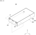
- Fig. 1 is an exploded perspective view of a battery module of the present disclosure.
- Fig. 2 is a perspective view which shows a battery module in which components of Fig. 1 are assembled.
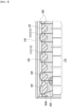
- Fig. 3 is a diagram which enlarges and shows a state cut along the section P1 of Fig. 2 .
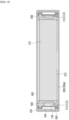
- Fig. 4 is a diagram which enlarges and shows a state cut along the section P2 of Fig. 2 .
- Fig. 11 is a perspective view which shows a battery cell included in the battery module of the present disclosure.
- a battery module 100 includes a battery cell stack 120 in which a plurality of battery cells 110 are stacked, and a module frame 200 that surrounds the battery cell stack 120.
- the battery cell 110 is preferably a pouch-type battery cell, and can be formed in a rectangular sheet-like structure.
- the battery cell 110 according to the present embodiment has a structure in which two electrode leads 111 and 112 face each other and protrude from one end part 114a and the other end part 114b of the cell main body 113, respectively. That is, the battery cell 110 includes electrode leads 111 and 112 that are protruded in mutually opposite directions. More specifically, the electrode leads 111 and 112 are connected to an electrode assembly (not shown), and are protruded from the electrode assembly (not shown) to the outside of the battery cell 110.
- the battery cell 110 can be produced by joining both end parts 114a and 114b of a cell case 114 and one side part 114c connecting them in a state in which an electrode assembly (not shown) is housed in a cell case 114.
- the battery cell 110 according to the present embodiment has a total of three sealing parts 114sa, 114sb and 114sc, wherein the sealing parts 114sa, 114sb and 114sc have a structure that is sealed by a method such as heat-sealing, and the remaining other side part may be composed of a connection part 115.
- the cell case 114 may be composed of a laminated sheet including a resin layer and a metal layer.
- connection part 115 may extend long along one edge of the battery cell 110, and a bat-ear 110p may be formed at an end of the connection part 115.
- a terrace part 116 may be formed between the electrode leads 111 and 112 and the cell main body 113. That is, the battery cell 110 may include a terrace part 116 formed to extend from the cell case 114 in the direction in which the electrode leads 111 and 112 protrude.
- Such a battery cell 110 may be composed by a plurality of numbers, and the plurality of battery cells 110 may be stacked so as to be electrically connected to each other, thereby forming a battery cell stack 120. Particularly, as shown in Fig. 1 , a plurality of battery cells 110 may be stacked along the direction parallel to the y-axis. Thereby, the electrode leads 111 and 112 may protrude in the x-axis direction and the -x-axis direction, respectively.
- the module frame 200 may include a frame member 300 which is opened in the upper surface, the front surface and the rear surface thereof and covers the lower part and both side parts of the battery cell stack 120, and an upper plate 400 that covers an upper part of the battery cell stack 120.
- the module frame 200 is not limited thereto, and can be replaced with a frame having another shape such as an L-shaped frame or a mono-frame that surrounds the battery cell stack 120 except the front and rear surfaces thereof.
- the battery cell stack 120 housed inside the module frame 200 can be physically protected through the module frame 200.
- the frame member 300 may include a bottom part 300a supporting the lower part of the battery cell stack 120, and side surface parts 300b each extending upward from both ends of the bottom part 300a.
- the upper plate 400 may cover the opened upper side surface of the module frame 200.
- the end plate 150 can cover the front and rear surfaces of the battery cell stack 120 that are opened in the module frame 200.
- the end plate 150 can be weld-coupled with the front and rear end edges of the upper plate 400 and the front and rear end edges of the module frame 200.
- a bus bar frame 130 can be formed between the end plate 150 and the front and rear surfaces of the battery cell stack 120.
- the plurality of bus bars 160 mounted on the bus bar frame 130 are formed so as to protrude from the battery cells 110, and can come into contact with the electrode leads 111 and 112 mounted on the bus bar frame 130.
- the battery module 100 further includes a thermal conductive resin layer 310 located between the lower surface of the battery cell stack 120 and the bottom part of the module frame 200, that is, the bottom part 300a of the frame member 300, wherein the thermal conductive resin layer 310 can play a role of transferring heat generated from the battery cell 110 to the bottom of the battery module 100 and fixing the battery cell stack 120.
- a conventional battery module is configured such that heat generated in the battery cells is discharged through the thermal conductive resin layer formed at a lower part of the battery cell.
- the thermal conductive resin layer had a problem that it cannot efficiently cool the electrode leads and bus bar frames on the front surface and the rear surface of the battery cells and bus bars mounted on the bus bar frames.
- the conventional battery module had a problem that a space between the battery cell stack and the bus bar frame and a space between the bus bar frame and the end plate are formed as empty spaces, and thus, insulation performance deteriorates due to inflow of moisture or foreign matter. Therefore, in a situation where the electrode leads and bus bars of the battery cell are made to generate high heat in a short period of time by the flow of high current, such as rapid charging, a structure capable of effectively cooling the heat generation is required.
- the conventional battery module had a problem that due to the gas generated through the decomposition or side reaction of the electrolyte in the battery cell, when a gas pocket occurs in which the inner area of the sealing part, such as the cell body of the battery cell and the terrace part, protrudes and swells, it is not possible to detect definitively whether a gas pocket has occurred. Particularly, a portion of a battery cell adjacent to an electrode lead and a sealing part swells due to the gas pocket, which increases the risk of damage to the battery cell. Therefore, when the gas pocket occurs, it contains a material that flows due to the occurrence of the gas pocket, and a structure capable of sensing the occurrence of gas pockets by detecting the flow and movement of the material is needed. In addition, by sensing the gas pocket, it may be possible to diagnose the occurrence of abnormality in battery cells.
- the battery module 100 includes a heat transfer member 500 formed between the battery cell stack 120 and the end plate 150, and further includes a movement sensing units 400H, 700 and 800 for sensing the movement of the heat transfer member 500.
- the heat transfer member 500 may be formed in a space between the battery cell stack 120 and the bus bar frame 130 and a space between the bus bar frame 130 and the end plate 150.
- an insulating cover may be further formed in the space between the bus bar frame 130 and the end plate 150, so that the heat transfer member 500 can fill the space between the bus bar frame 130 and the insulating cover.
- the heat transfer member 500 may entirely fill the above-mentioned spaces. That is, the heat transfer member 500 may entirely fill the space between the battery cell stack 120 and the bus bar frame 130 and the space between the bus bar frame 130 and the end plate 150. Therefore, through the heat transfer member 500 that has entirely filled, the insulation performance is improved, and the possibility of penetration of moisture and foreign matter is minimized, thereby improving the stability of the battery module. When moisture or foreign matter penetrates from the outside, a short circuit may occur in the bus bar 160 and the life of the battery module 100 may be shortened. Therefore, the heat transfer member 500 prevents moisture and foreign matter from penetrating into the battery module and contacting the bus bar 160 and the electrode leads 111 and 112, thereby capable of securing the performance of the battery module and improving the stability.
- the heat transfer member 500 may come into contact with the electrode leads 111 and 112.
- the electrode leads 111 and 112 which are portions where a large amount of heat is generated in battery cell 110, are portions requiring the most cooling among portions of the battery cell 110.
- effective cooling of the electrode leads 111 and 112 is possible by the heat transfer member 500.
- the heat transfer member 500 may come into surface contact with the electrode leads 111 and 112, and as the contact area increases, effective cooling may be enabled even if a large amount of heat generates by the contact.
- the heat transfer member 500 may also come into contact with the bus bar 160 and the bus bar frame 130. Heat generated from the bus bar 160 can be cooled through the heat transfer member 500 and can be quickly transferred through other components in contact with the heat transfer member 500. Further, the heat transfer member 500 comes into contact with each of the plurality of bus bars 160 formed in the battery module 100, thereby capable of preventing physical contact between the bus bars 160. Therefore, it is possible to interrupt a short circuit or the like that may occur due to contact between the bus bars 160.
- the heat transfer member 500 may come into contact with the bottom part of the module frame 200 and the upper part of the module frame 200. That is, the heat transfer member 500 may come into contact with the bottom part 300a of the frame member 300 and the upper plate 400.
- the heat transfer member 500 may be formed so as to come into contact with the bottom part 300a of the frame member 300 and the thermal conductive resin layer 310. Further, the heat transfer member 500 may be formed so as to come into contact with the upper plate 400. Therefore, the heat transfer member 500 comes into contact with the bottom part 300a of the frame member 300, the thermal conductive resin layer 310 and the upper plate 400 to form an additional heat transfer path, which makes it possible to transfer and dissipate heat to the outside of the module. At this time, the heat transfer member 500 may come into surface contact with the configurations described above. Since the heat transfer member 500 is formed in the form of filling a space, it is possible to achieve improved cooling efficiency by coming into surface contact with the above components.
- the heat transfer member 500 may be formed so as to come into contact with a plurality of components.
- the heat transfer member 500 comes into direct contact with the bus bar 160 and the electrode leads 111 and 112, and heat generated from the bus bar 160 and the electrode leads 111 and 112 is immediately transferred through multiple components, thereby improving the temperature deviation between components in the battery module, especially the parts of the battery cells.
- the heat transfer member 500 may be formed of a material having fluidity.
- the heat transfer member 500 may include a heat transfer material that is injected and cured, but may include a gel form that is not completely cured. That is, the heat transfer member 500 may be formed in a gel form.
- As the heat transfer member 500 is formed in a gel form it is possible to secure the cooling performance and at the same time, have fluidity, and thus cope with changes in some components in the battery module. Therefore, the heat transfer member 500 can move in a situation, such as during the occurrence of a gas pocket 600 in the battery module, thereby capable of securing continuous cooling performance.
- the heat transfer member 500 may be formed of a material having thermal conductivity and may be formed of a material having insulation properties. Therefore, by forming the heat transfer member 500, it is possible to achieve the effect of improving the cooling performance and insulation performance through heat transfer.
- Fig. 5 is a diagram which shows a movement sensing unit of a battery module according to one embodiment of the present disclosure.
- Fig. 6 is a diagram which shows a movement sensing unit of a battery module according to another embodiment of the present disclosure.
- Fig. 7 is a diagram which enlarges and shows the section A of Fig. 6 .
- Fig. 8 is a diagram which shows a movement sensing unit of a battery module according to another embodiment of the present disclosure.
- Fig. 9 is a diagram which enlarges and shows the section B of Fig. 8 .
- Fig. 10 is a diagram which shows a movement sensing unit of a battery module according to another embodiment of the present disclosure.
- the movement sensing units 400H, 700 and 800 of the battery module include a pressure sensor 700, wherein the pressure sensor 700 may be formed so as to come into contact with the heat transfer member 500.
- the pressure sensor 700 may be formed anywhere in the battery module within a range coming into contact with the heat transfer member 500.
- the heat transfer member 500 can be compressed by the movement of the heat transfer member 500 to easily sense a pressure change, and the pressure sensor 700 can be formed on the bus bar frame 130 so as to ensure stable installation of the pressure sensor 700.
- the heat transfer member 500 in contact with the battery cell 110 moves through the electrode leads 111 and 112 and the like, thereby increasing the internal pressure.
- the space in which the heat transfer member 500 can exist becomes narrower, and a pressure change can be created as the heat transfer member 500 moves in the area where the gas pocket 600 occurs. Therefore, the pressure sensor 700 may sense the pressure change, and thus sense the occurrence of the gas pocket 600 in the battery cell 110 and the occurrence of abnormality in the battery cell 110 due to gas generation.
- the movement sensing units 400H, 700 and 800 of the battery module may include a hole 400H formed in the upper plate 400.
- the heat transfer member 500 may flow to the outside through the hole 400H of the upper plate 400.
- the hole 400H may be formed so as to pass through the upper plate 400. Therefore, as the heat transfer member 500 is pushed out by the gas pocket 600, it may flow to the outside along the hole 400H formed in the upper plate 400.
- the occurrence of the gas pocket 600 is related to the performance of the battery cell 110, it is possible to confirm the deterioration of the life of the battery cell 110 and diagnose the occurrence of an abnormality thereof by confirming the presence or absence of the gas pocket 600, and confirming the presence or absence of gas generation in the battery cell 110 accompanied therewith.
- the movement sensing units 400H, 700 and 800 of the battery module may further comprise a protruding member 800 that is formed so as to come into contact with the heat transfer member 500 and to be adjacent to the hole 400H. At this time, when the gas pocket 600 occurs, the protruding member 800 may move toward the outside of the upper plate 400.
- the protruding member 800 may be formed in a shape including a horizontal surface formed horizontally with the upper plate 400 and a vertical surface extending vertically from the horizontal surface. Further, the protruding member 800 may be formed between the upper part of the heat transfer member 500 and the inner surface of the upper plate 400. Therefore, the horizontal surface of the protruding member 800 may be fixed to the inner surface of the upper plate 400, and may be shaped such that the vertical surface passes through the hole 400H.
- the protruding member 800 is pushed upward due to the movement of the heat transfer member 500.
- the protruding member 800 moves upward, the vertical surface formed so as to pass through the hole 400H moves toward the outside of the upper plate 400, so that the vertical surface can be confirmed with the naked eye even from the outside. Therefore, it is possible to predict the presence or absence of occurrence of the gas pocket 600 and the degree of occurrence thereof by confirming the extent to which the vertical surface protrudes to the outside.
- the battery module according to another embodiment of the present disclosure further includes a groove part 400G formed inside the upper plate 400, and the protruding member 800 may be fitted into the groove part 400G.
- a groove part 400G that is recessed and formed from the hole 400H may be formed in the space between the outside surface and the inside surface of the upper plate 400.
- the groove part 400G may be formed on both side surfaces of the hole 400H.
- the horizontal surface of the protruding member 800 may be fitted into the groove part 400G.
- an extra space may be formed between the groove part 400G and the horizontal surface. Therefore, when the gas pocket 600 occurs, the protruding member 800 is raised due to the heat transfer member 500 flowing in through the hole 400H, so that the vertical surface of the protruding member 800 can protrude to the outside through the hole 400H. Therefore, it may be possible to predict the presence or absence of occurrence of the gas pocket 600 and the degree of occurrence thereof by confirming the extent to which the vertical surface protrudes to the outside.
- the movement sensing units 400H, 700 and 800 that sense the movement of the heat transfer member 500 due to the movement sensing units 400H, 700 and 800 that sense the movement of the heat transfer member 500 according to embodiments of the present disclosure, movement of the heat transfer member 500 during the occurrence of the gas pocket 600 can be confirmed with a sensor and naked eyes. Therefore, the occurrence of an abnormality in the battery cell 110 can be predicted by sensing the presence or absence of occurrence of the gas pocket 600 and the degree of occurrence thereof, thereby appropriately coping with the deterioration of the life and the occurrence of abnormality of the battery cell.
- the safety of the battery cell 110 and the battery module 100 can be ensured by sensing the occurrence of the gas pocket 600 by the heat transfer member 500 and the movement sensing units 400H, 700 and 800 that sense the movement of the heat transfer member 500 according to the embodiments of the present disclosure.
- a battery pack according to another embodiment of the present disclosure will be described below.
- a battery pack according to the present embodiment includes the battery module described above.
- the battery pack of the present disclosure may have a structure in which one or more of the battery modules according to the present embodiment are gathered, and packed together with a battery management system (BMS) and a cooling device that control and manage battery's temperature, voltage, etc.
- BMS battery management system
- the battery pack can be applied to various devices.
- a device can be applied to a vehicle means such as an electric bicycle, an electric vehicle, or a hybrid vehicle, but the present disclosure is not limited thereto, and is applicable to various devices that can use a battery module, which is also falls under the scope of the present disclosure.
Landscapes
- Chemical & Material Sciences (AREA)
- Chemical Kinetics & Catalysis (AREA)
- Electrochemistry (AREA)
- General Chemical & Material Sciences (AREA)
- Engineering & Computer Science (AREA)
- Manufacturing & Machinery (AREA)
- Microelectronics & Electronic Packaging (AREA)
- Battery Mounting, Suspending (AREA)
- Connection Of Batteries Or Terminals (AREA)
- Secondary Cells (AREA)
Applications Claiming Priority (2)
| Application Number | Priority Date | Filing Date | Title |
|---|---|---|---|
| KR1020210132639A KR20230049454A (ko) | 2021-10-06 | 2021-10-06 | 전지 모듈 및 이를 포함하는 전지 팩 |
| PCT/KR2022/014179 WO2023058956A1 (ko) | 2021-10-06 | 2022-09-22 | 전지 모듈 및 이를 포함하는 전지 팩 |
Publications (1)
| Publication Number | Publication Date |
|---|---|
| EP4270602A1 true EP4270602A1 (en) | 2023-11-01 |
Family
ID=85804488
Family Applications (1)
| Application Number | Title | Priority Date | Filing Date |
|---|---|---|---|
| EP22878777.6A Pending EP4270602A1 (en) | 2021-10-06 | 2022-09-22 | Battery module and battery pack comprising same |
Country Status (6)
| Country | Link |
|---|---|
| US (1) | US20240170758A1 (zh) |
| EP (1) | EP4270602A1 (zh) |
| JP (1) | JP2024506172A (zh) |
| KR (1) | KR20230049454A (zh) |
| CN (1) | CN116802894A (zh) |
| WO (1) | WO2023058956A1 (zh) |
Family Cites Families (5)
| Publication number | Priority date | Publication date | Assignee | Title |
|---|---|---|---|---|
| AU2011284656A1 (en) * | 2010-07-29 | 2013-02-21 | E4V | System for cooling an electrical battery, and battery including such a system |
| KR101750479B1 (ko) * | 2015-01-13 | 2017-06-23 | 주식회사 엘지화학 | 열전도 부재를 포함하는 전지팩 |
| CN111051434B (zh) * | 2017-07-24 | 2022-03-29 | 陶氏东丽株式会社 | 多成分硬化型导热性硅酮凝胶组合物、导热性部件及散热构造体 |
| KR20210066528A (ko) * | 2019-11-28 | 2021-06-07 | 주식회사 엘지에너지솔루션 | 전지 모듈 및 이를 포함하는 전지 팩 |
| KR20210092563A (ko) * | 2020-01-16 | 2021-07-26 | 주식회사 엘지에너지솔루션 | 전지 모듈 및 이를 포함하는 전지팩 |
-
2021
- 2021-10-06 KR KR1020210132639A patent/KR20230049454A/ko active Search and Examination
-
2022
- 2022-09-22 WO PCT/KR2022/014179 patent/WO2023058956A1/ko active Application Filing
- 2022-09-22 CN CN202280010530.7A patent/CN116802894A/zh active Pending
- 2022-09-22 JP JP2023547685A patent/JP2024506172A/ja active Pending
- 2022-09-22 US US18/282,769 patent/US20240170758A1/en active Pending
- 2022-09-22 EP EP22878777.6A patent/EP4270602A1/en active Pending
Also Published As
| Publication number | Publication date |
|---|---|
| WO2023058956A1 (ko) | 2023-04-13 |
| JP2024506172A (ja) | 2024-02-09 |
| KR20230049454A (ko) | 2023-04-13 |
| US20240170758A1 (en) | 2024-05-23 |
| CN116802894A (zh) | 2023-09-22 |
Similar Documents
| Publication | Publication Date | Title |
|---|---|---|
| US20140242429A1 (en) | Battery module of improved safety and battery pack containing the same | |
| EP3958379B1 (en) | Battery module and battery pack including the same | |
| EP4087037A1 (en) | Battery pack and device including same | |
| EP4181293A1 (en) | Battery module and battery pack including same | |
| EP4181309A1 (en) | Battery module and battery pack comprising same | |
| US20230347755A1 (en) | Battery module and battery pack including the same | |
| US20230327231A1 (en) | Battery module and battery pack including the same | |
| EP4270602A1 (en) | Battery module and battery pack comprising same | |
| EP4099481A1 (en) | Battery module and battery pack including same | |
| EP4243159A1 (en) | Battery module and battery pack including same | |
| EP4318736A1 (en) | Battery module and battery pack including same | |
| KR20210090917A (ko) | 전지 모듈 및 이를 포함하는 전지팩 | |
| US20240186613A1 (en) | Battery module and battery pack including the same | |
| EP4366038A1 (en) | Battery module and battery pack including same | |
| EP4376141A1 (en) | Battery module and battery pack including same | |
| EP4261985A1 (en) | Battery pack and device including same | |
| EP4210154A1 (en) | Battery pack and device comprising same | |
| EP4391156A1 (en) | Battery pack and device comprising same | |
| US20230261307A1 (en) | Battery pack and device including the same | |
| US20230318078A1 (en) | Battery module and battery pack including the same | |
| EP4250452A1 (en) | Battery pack and device including same | |
| KR20230036864A (ko) | 전지 모듈 및 이를 포함하는 전지 팩 | |
| KR20230111916A (ko) | 전지 모듈 및 이를 포함하는 전지 팩 | |
| KR20220161057A (ko) | 전지 모듈 및 이를 포함하는 전지팩 | |
| KR20210016296A (ko) | 다기능 엔드 플레이트를 갖는 전지 모듈 |
Legal Events
| Date | Code | Title | Description |
|---|---|---|---|
| STAA | Information on the status of an ep patent application or granted ep patent |
Free format text: STATUS: THE INTERNATIONAL PUBLICATION HAS BEEN MADE |
|
| PUAI | Public reference made under article 153(3) epc to a published international application that has entered the european phase |
Free format text: ORIGINAL CODE: 0009012 |
|
| STAA | Information on the status of an ep patent application or granted ep patent |
Free format text: STATUS: REQUEST FOR EXAMINATION WAS MADE |
|
| 17P | Request for examination filed |
Effective date: 20230726 |
|
| AK | Designated contracting states |
Kind code of ref document: A1 Designated state(s): AL AT BE BG CH CY CZ DE DK EE ES FI FR GB GR HR HU IE IS IT LI LT LU LV MC MK MT NL NO PL PT RO RS SE SI SK SM TR |