EP4270570A1 - Reform pin - Google Patents
Reform pin Download PDFInfo
- Publication number
- EP4270570A1 EP4270570A1 EP22890176.5A EP22890176A EP4270570A1 EP 4270570 A1 EP4270570 A1 EP 4270570A1 EP 22890176 A EP22890176 A EP 22890176A EP 4270570 A1 EP4270570 A1 EP 4270570A1
- Authority
- EP
- European Patent Office
- Prior art keywords
- reform
- pin
- diameter
- electrode assembly
- head portion
- Prior art date
- Legal status (The legal status is an assumption and is not a legal conclusion. Google has not performed a legal analysis and makes no representation as to the accuracy of the status listed.)
- Pending
Links
Images






Classifications
-
- H—ELECTRICITY
- H01—ELECTRIC ELEMENTS
- H01M—PROCESSES OR MEANS, e.g. BATTERIES, FOR THE DIRECT CONVERSION OF CHEMICAL ENERGY INTO ELECTRICAL ENERGY
- H01M10/00—Secondary cells; Manufacture thereof
- H01M10/04—Construction or manufacture in general
- H01M10/0431—Cells with wound or folded electrodes
-
- H—ELECTRICITY
- H01—ELECTRIC ELEMENTS
- H01M—PROCESSES OR MEANS, e.g. BATTERIES, FOR THE DIRECT CONVERSION OF CHEMICAL ENERGY INTO ELECTRICAL ENERGY
- H01M10/00—Secondary cells; Manufacture thereof
- H01M10/04—Construction or manufacture in general
- H01M10/0404—Machines for assembling batteries
- H01M10/0409—Machines for assembling batteries for cells with wound electrodes
-
- H—ELECTRICITY
- H01—ELECTRIC ELEMENTS
- H01M—PROCESSES OR MEANS, e.g. BATTERIES, FOR THE DIRECT CONVERSION OF CHEMICAL ENERGY INTO ELECTRICAL ENERGY
- H01M10/00—Secondary cells; Manufacture thereof
- H01M10/04—Construction or manufacture in general
- H01M10/0422—Cells or battery with cylindrical casing
-
- H—ELECTRICITY
- H01—ELECTRIC ELEMENTS
- H01M—PROCESSES OR MEANS, e.g. BATTERIES, FOR THE DIRECT CONVERSION OF CHEMICAL ENERGY INTO ELECTRICAL ENERGY
- H01M10/00—Secondary cells; Manufacture thereof
- H01M10/05—Accumulators with non-aqueous electrolyte
- H01M10/058—Construction or manufacture
- H01M10/0587—Construction or manufacture of accumulators having only wound construction elements, i.e. wound positive electrodes, wound negative electrodes and wound separators
-
- Y—GENERAL TAGGING OF NEW TECHNOLOGICAL DEVELOPMENTS; GENERAL TAGGING OF CROSS-SECTIONAL TECHNOLOGIES SPANNING OVER SEVERAL SECTIONS OF THE IPC; TECHNICAL SUBJECTS COVERED BY FORMER USPC CROSS-REFERENCE ART COLLECTIONS [XRACs] AND DIGESTS
- Y02—TECHNOLOGIES OR APPLICATIONS FOR MITIGATION OR ADAPTATION AGAINST CLIMATE CHANGE
- Y02E—REDUCTION OF GREENHOUSE GAS [GHG] EMISSIONS, RELATED TO ENERGY GENERATION, TRANSMISSION OR DISTRIBUTION
- Y02E60/00—Enabling technologies; Technologies with a potential or indirect contribution to GHG emissions mitigation
- Y02E60/10—Energy storage using batteries
-
- Y—GENERAL TAGGING OF NEW TECHNOLOGICAL DEVELOPMENTS; GENERAL TAGGING OF CROSS-SECTIONAL TECHNOLOGIES SPANNING OVER SEVERAL SECTIONS OF THE IPC; TECHNICAL SUBJECTS COVERED BY FORMER USPC CROSS-REFERENCE ART COLLECTIONS [XRACs] AND DIGESTS
- Y02—TECHNOLOGIES OR APPLICATIONS FOR MITIGATION OR ADAPTATION AGAINST CLIMATE CHANGE
- Y02E—REDUCTION OF GREENHOUSE GAS [GHG] EMISSIONS, RELATED TO ENERGY GENERATION, TRANSMISSION OR DISTRIBUTION
- Y02E60/00—Enabling technologies; Technologies with a potential or indirect contribution to GHG emissions mitigation
- Y02E60/30—Hydrogen technology
- Y02E60/50—Fuel cells
-
- Y—GENERAL TAGGING OF NEW TECHNOLOGICAL DEVELOPMENTS; GENERAL TAGGING OF CROSS-SECTIONAL TECHNOLOGIES SPANNING OVER SEVERAL SECTIONS OF THE IPC; TECHNICAL SUBJECTS COVERED BY FORMER USPC CROSS-REFERENCE ART COLLECTIONS [XRACs] AND DIGESTS
- Y02—TECHNOLOGIES OR APPLICATIONS FOR MITIGATION OR ADAPTATION AGAINST CLIMATE CHANGE
- Y02P—CLIMATE CHANGE MITIGATION TECHNOLOGIES IN THE PRODUCTION OR PROCESSING OF GOODS
- Y02P70/00—Climate change mitigation technologies in the production process for final industrial or consumer products
- Y02P70/50—Manufacturing or production processes characterised by the final manufactured product
Definitions
- the present invention relates to a reform pin, and more particularly, to a reform pin for uniformly forming a jelly-roll shape when an electrode assembly of a cylindrical battery is manufactured.
- Lithium batteries are being applied to various industrial fields, such as mobile application devices, automobiles, robots, and energy storage devices, as a response to today's environmental regulations and high oil price issues.
- Such lithium batteries are generally classified into cylindrical, prismatic, or pouch types according to the shape of an exterior material in which the electrode assembly is accommodated.
- the cylindrical battery is provided in a battery pack (Cell To Pack, CTP) structure consisting of a plurality of battery cells. Accordingly, as compared to a prismatic or pouch-type battery provided in a battery pack structure consisting of a plurality of battery modules, the cylindrical battery has advantages in that a packaging size may be reduced and mass production is possible due to a standardized size.
- CTP Cell To Pack
- the cylindrical battery includes a jelly roll-shaped electrode assembly consisting of a positive electrode plate, a separation membrane, and a negative electrode plate.
- the electrode assembly having a jelly roll structure is provided by winding the electrode assembly by using a winding core.
- the winding core contacts a negative electrode tab and one side of a hollow portion of the electrode assembly to serve as a support when the electrode assembly is wound. Accordingly, when the winding core is removed after winding the electrode assembly, a sidewall of the electrode assembly that is in contact with the winding core may be separated to form a separation membrane.
- a reforming process for maintaining the shape of the jelly roll is performed as a post-process.
- a reforming process is a process for molding an electrode assembly in a shape of a jelly roll, and progresses in the form of inserting a reform pin into a portion from which the winding core is removed, and pushing a separation membrane separated from the electrode assembly into the inner wall of the electrode assembly and making the separation membrane be in close contact with the inner wall.
- the reforming process was performed by using a reform pin provided with a conical head portion, but there are disadvantages in that the electrode assembly and the reform pin are in surface contact with each other, which makes it difficult to remove the separation membrane when the inserted reform pin is removed, and the reforming in the direction of the negative electrode tab is difficult.
- the present invention is to solve the problems of the prior art, and to provide a reform pin having high performance and high reliability.
- an exemplary embodiment of the present invention provides a reform pin for insertion into a hollow portion of an electrode assembly to reform a separation membrane defining an inner wall of the hollow portion, the reform pin including: a cylindrical shaped body portion having a first diameter; and a head portion having a vertex at a first end, and a second end connected to an end of the body portion, in which a second diameter of a circle at a vertical cross-section at any one point of the head portion is formed larger than the first diameter.
- a diameter of a vertical cross-section of the head portion may gradually decrease in a direction of the first end.
- a diameter of a vertical cross-section of the head portion may gradually decreases in a direction of the second end connected to the body portion.
- a length of the second diameter may correspond to a width of the hollow portion of the electrode assembly.
- the vertex of the head portion may be located at any one point in a virtual region having a third diameter shorter than the second diameter with respect to a central axis of the body portion.
- the electrode assembly may be wound in a shape of a jelly roll.
- the reform pin may be used during a reforming process of the electrode assembly.
- one end of the head portion extending from the body portion is provided thicker than the body portion, so that a contact surface with an inner surface of an electrode assembly is reduced when an inserted reform pin is removed from the electrode assembly, thereby stably removing the reform pin without lifting of a separation membrane.
- the vertex of the head portion is formed to be inclined to one side, it is possible to provide a high-performance and highly reliable reform pin that may be easily inserted while avoiding the separation membrane in which a lifting phenomenon occurs when the reform pin is inserted into the hollow portion of the electrode assembly.
- first, second, A, and B are used for describing various constituent elements, but the constituent elements are not limited by the terms. The terms are used only to discriminate one constituent element from another constituent element. For example, without departing from the scope of the invention, a first constituent element may be named as a second constituent element, and similarly a second constituent element may be named as a first constituent element.
- a term "and/or" includes a combination of multiple relevant described items or any one of the multiple relevant described items.
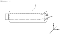
- FIG. 1 is an image of a reform pin inserted into an electrode structure.
- the reform pin is used in the manufacturing of a cylindrical battery having a Cell To Pack (CTP) structure.
- CTP Cell To Pack
- the reform pin is used in a reforming process when a cylindrical battery is manufactured, the reform pin penetrates a hollow portion of an electrode assembly JR wound in the shape of a jelly roll by a winding core, and a separation membrane generated by frictional force when the winding core is removed may be fixed to an inner wall of the electrode assembly JR.
- FIG. 2 is an image of an electrode structure wound by a winding core.
- the electrode assembly JR is provided in a structure in which a separation membrane is laminated between a positive electrode plate and a negative electrode plate, and is wound in the form of a jelly roll by a winding core.
- a positive electrode tab is attached to an uncoated region in which an active layer is not formed in a positive electrode plate
- a negative electrode tab is attached to an uncoated region in which an active layer is not formed in a negative electrode plate.
- the separation membrane D may be damaged by the insertion of a welding rod when the electrode assembly JR is later inserted into a can and a CTW(Cylindrical Tab Welding) process is performed.
- the CTW process may be a process of welding the negative electrode tab of the electrode assembly JR to the bottom of the can. Therefore, when the electrode assembly JR is manufactured, a reform process may be performed so that the electrode assembly JR maintains the shape of the jelly roll for a long time without damaging the separation membrane.
- a reform pin is inserted into a hollow portion H of the electrode structure from which the winding core has been removed, and the Sine wave shaped separation membrane D is pushed in the outer direction of the hollow portion H, to prevent damage due to lifting of the separation membrane.
- the reform pin in the related art will be described with reference to FIGS. 3 and 4 below.
- FIG. 3 is a cross-sectional view of the reform pin in the related art in FIG. 1 cut along the y-axis
- FIG. 4 is a cross-sectional view of the reform pin in the related art in FIG. 1 cut along the x-axis.
- the reform pin in the related art was provided in a three-dimensional form including a cylindrical body portion B and a conical head portion T.
- the reform pin in the related art is provided so that a diameter of the body portion B corresponds to a width of the hollow portion H, so that there are disadvantages in that when the cylindrical reform pin is inserted into the hollow portion H of the electrode assembly, reforming is easy only for the separation membrane in the vicinity of the positive electrode tab where the body portion B is located, and the reforming efficiency in the vicinity of the negative electrode tab where the conical-shaped head portion T is located is lowered.
- the lifting phenomenon is improved only for the separation membrane at one end where the positive electrode tab is formed, and the reforming is difficult for the separation membrane at the other end where the negative electrode tab is formed.
- a diameter of the reform pin in the related art was manufactured with 3.15 pi, which is 0.25 pi different from a diameter of the winding core.
- the body portion B is provided in a cylindrical shape corresponding to the width of the hollow portion H, so that the reform pin is in surface contact with the inner wall of the electrode assembly JR.
- the reform pin in the related art since the reform pin in the related art has a large contact area with the electrode assembly JR, so that when the reform pin is removed from the electrode assembly for the CTW process, the lifting phenomenon of the separation membrane D may occur again due to frictional force, similar to the case of removing the winding core. Therefore, when the reform pin in the related art is used, there is a disadvantage in that it is difficult to reform the electrode assembly with high reliability.
- a reform pin capable of reforming an electrode assembly with high performance and high reliability by providing a reform pin in the form of a wad in which a diameter of a cross-section at any one point of a head portion is wider than a diameter of a cross-section of a body portion and minimizing a contact with a separation membrane when the reform pin is inserted into a hollow portion of an electrode assembly for a reform process will be described.
- FIG. 5 is an image of a reform pin inserted into an electrode structure according to an exemplary embodiment of the present invention.
- the reform pin according to the exemplary embodiment of the present invention may be inserted into the hollow portion of an electrode structure to reform a positive electrode tab, a negative electrode tab, and a separation membrane.
- the structure of the reform pin will be described in more detail with reference to FIGS. 6 and 7 below.
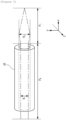
- FIG. 6 is a cross-sectional view of the reform pin according to the exemplary embodiment of the present invention in FIG. 5 taken along the y-axis
- FIG. 7 is a cross-sectional view of the reform pin according to the exemplary embodiment of the present invention in FIG. 5 taken along the x-axis.
- the reform pin may include a body portion P B and a head portion P T .
- the reform pin may be provided in the form of a wad in which the head portion P T is larger than the body portion P B .
- the body portion P B may be provided in a cylindrical shape having a first diameter R 1 .
- the first diameter R 1 may be smaller than the diameter of the cross section of a hollow portion H of an electrode assembly JR.
- the head portion P T may be connected to one end of the body portion P B . More specifically, a vertex P may be formed at one end of the head portion P T , and one end of the body portion P B may be connected to the other end of the head portion P T .
- the head portion P T may include any one point having a vertical cross section of a second diameter R 2 larger than the first diameter R 1 of the body portion P B .
- the head portion P T may be provided as a rotating body having an arrowhead shape.
- the second diameter R 2 may be manufactured with 3.2 pi, which is 0.2 pi different from the winding core.
- the head portion P T may be divided into a first portion A 1 and a second portion A 2 based on any one point having the second diameter R 2 .
- the first portion A 1 may be a portion between the vertex and any one point having a second diameter R 2
- the second portion A 2 may be a portion between any one point having the second diameter R 2 and one end of the body portion P B .
- the length of the diameter of the head portion P T in the first portion A 1 may gradually decrease from any one point having the second diameter R 2 toward the vertex.
- the head portion P T in the first portion A 1 may be provided in a conical shape.
- the length of the diameter of the head portion P T in the second portion A 2 may gradually decrease from any one point having the second diameter R 2 toward the one end of the body portion P B .
- the head portion P T in the second portion A 2 may be provided in a frustoconical shape.
- the vertex P of the head portion P T may be located at any one point in the virtual region having a third diameter R 3 with respect to a central axis C in the horizontal direction.
- the vertex P of the head portion P T may be located on the central axis C.
- the vertex P of the head portion P T may be positioned to be biased toward one side.
- the vertex P of the head portion P T is provided inclined at a predetermined angle in one direction, so that when the reform pin is inserted into the hollow portion H of the electrode assembly JR, the reform pin may be easily inserted into a region S (refer to FIG. 8 to be described later) by avoiding the separation membrane D in which the lifting phenomenon occurs.
- the length of the second diameter R 2 at any one point of the head portion P T may correspond to the width of the hollow portion H of the electrode assembly.
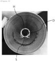
- FIG. 8 is an image of an electrode structure wound by the reform pin according to the exemplary embodiment of the present invention.
- the reform pin according to the exemplary embodiment of the present invention is provided in a larger size in at least one point of the head portion P T than that of the body portion P B , when the electrode assembly JR in which the hollow portion H is formed is inserted, the body portion P B may not come into contact with the inner surface of the electrode assembly JR due to the size of the head portion P T . Accordingly, since the reform pin according to the exemplary embodiment of the present invention has a small contact area with the electrode assembly JR and friction is minimized, so that when the reform pin is removed from the electrode assembly JR, the reform pin may be stably removed without lifting of the separation membrane D.
- the reform pin according to the exemplary embodiment of the present invention may minimize friction force and be manufactured in a micro-size, the reform pin may be easily inserted up to the vicinity of the negative electrode tab of the electrode assembly JR. Therefore, since it is possible to reform the separation membrane in the vicinity of the negative electrode tab as well as in the vicinity of the positive electrode tab, a reforming effect with high efficiency and high reliability may be expected compared to the reform pin in the related art that only reformed the separation membrane in the vicinity of the positive electrode tab.
- the reform pin according to the exemplary embodiment of the present invention rotates the winding core after the winding of the electrode assembly JR is completed, thereby detecting the defect of the electrode assembly JR that occurs when the inner separation membrane of the electrode assembly JR is primarily reformed.
- the reform pin according to the exemplary embodiment of the present invention since the reform pin according to the exemplary embodiment of the present invention is provided in a larger size in at least one point of the head portion P T than that of the body portion P B , when the electrode assembly is defective, it may be difficult for the reform pin to be inserted into the hollow portion H. Therefore, the reform pin according to the exemplary embodiment of the present invention may detect a defect in the electrode assembly JR before the cylindrical can is assembled.
- FIG. 9 is an image of an electrode structure in which a positive electrode tab wound by using a reform pin in the related art according to a comparative example of the present invention is positioned
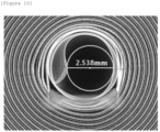
- FIG. 10 is an image of an electrode structure in which a negative electrode tab wound by using a reform pin in the related art according to a comparative example of the present invention is positioned.
- the diameter in the vicinity of the positive electrode tab formed in the portion of the insertion end was measured to be 2.880 mm, and the diameter of the vicinity of the negative electrode tab was measured to be 2.538 mm.
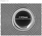
- FIG. 11 is an image of an electrode structure in which a positive electrode tab wound by using a reform pin according to an experimental example of the present invention is positioned
- FIG. 12 is an image of an electrode structure in which a negative electrode tab wound by using the reform pin according to an experimental example of the present invention is positioned.
- the diameter of the vicinity of the positive electrode tab formed in the portion of the insertion end was measured to be 2.909 mm, and the diameter in the vicinity of the negative electrode tab was measured to be 2.809 mm.
- the diameter of the hollow portion in the vicinity of the positive electrode tab is enlarged by about 0.030 mm compared to the reform formation using the reform pin in the related art, so that it can be seen that the separation membrane molding is improved to a level of 1.0%.
- the diameter of the hollow portion in the vicinity of the negative electrode tab is enlarged by about 0.268 mm compared to the reform formation using the reform pin in the related art, so that it can be seen that the separation membrane molding is improved to the level of 10.6%.
- one end of the head portion extending from the body portion is provided thicker than the body portion, so that the contact surface with the inner surface of the electrode assembly is reduced when the inserted reform pin is removed from the electrode assembly, thereby stably removing the reform pin without lifting of the separation membrane.
- the vertex of the head portion is formed to be inclined to one side, it is possible to provide a high-performance and highly reliable reform pin that may be easily inserted while avoiding the separation membrane in which a lifting phenomenon occurs when the reform pin is inserted into the hollow portion of the electrode assembly.
- the operation of the method according to the exemplary embodiment of the present invention may be implemented as a computer-readable program or code on a computer-readable recording medium.
- the computer-readable recording medium includes all types of recording devices in which data readable by a computer system is stored.
- the computer-readable recording medium may be distributed in a network-connected computer system to store and execute computer-readable programs or codes in a distributed manner.
- the computer-readable recording medium may include a hardware device, such as a ROM, a RAM, and a flash memory, specially configured to store and execute program instructions.
- the program instructions may include not only machine language codes such as those generated by a compiler, but also high-level language codes that can be executed by a computer by using an interpreter or the like.
- a block or apparatus corresponds to a method step or feature of a method step.
- aspects described in the context of a method may also represent a feature of a corresponding block or item or a corresponding apparatus.
- Some or all of the method steps may be performed by (or using) a hardware device, such as, for example, a microprocessor, a programmable computer, or an electronic circuit. In some exemplary embodiments, one or more of the most important method steps may be performed by such an apparatus.
Landscapes
- Engineering & Computer Science (AREA)
- Manufacturing & Machinery (AREA)
- Chemical & Material Sciences (AREA)
- Chemical Kinetics & Catalysis (AREA)
- Electrochemistry (AREA)
- General Chemical & Material Sciences (AREA)
- Secondary Cells (AREA)
Abstract
Description
- This application claims priority to and the benefit of
Korean Patent Application No. 10-2021-0152370 filed in the Korean Intellectual Property Office on November 8, 2021 - The present invention relates to a reform pin, and more particularly, to a reform pin for uniformly forming a jelly-roll shape when an electrode assembly of a cylindrical battery is manufactured.
- Lithium batteries are being applied to various industrial fields, such as mobile application devices, automobiles, robots, and energy storage devices, as a response to today's environmental regulations and high oil price issues.
- Such lithium batteries are generally classified into cylindrical, prismatic, or pouch types according to the shape of an exterior material in which the electrode assembly is accommodated.
- Among them, the cylindrical battery is provided in a battery pack (Cell To Pack, CTP) structure consisting of a plurality of battery cells. Accordingly, as compared to a prismatic or pouch-type battery provided in a battery pack structure consisting of a plurality of battery modules, the cylindrical battery has advantages in that a packaging size may be reduced and mass production is possible due to a standardized size.
- On the other hand, the cylindrical battery includes a jelly roll-shaped electrode assembly consisting of a positive electrode plate, a separation membrane, and a negative electrode plate.
- The electrode assembly having a jelly roll structure is provided by winding the electrode assembly by using a winding core.
- In more detail, the winding core contacts a negative electrode tab and one side of a hollow portion of the electrode assembly to serve as a support when the electrode assembly is wound. Accordingly, when the winding core is removed after winding the electrode assembly, a sidewall of the electrode assembly that is in contact with the winding core may be separated to form a separation membrane.
- Accordingly, during the manufacturing of the electrode assembly, a reforming process for maintaining the shape of the jelly roll is performed as a post-process.
- In general, a reforming process is a process for molding an electrode assembly in a shape of a jelly roll, and progresses in the form of inserting a reform pin into a portion from which the winding core is removed, and pushing a separation membrane separated from the electrode assembly into the inner wall of the electrode assembly and making the separation membrane be in close contact with the inner wall.
- At this time, in the related art, the reforming process was performed by using a reform pin provided with a conical head portion, but there are disadvantages in that the electrode assembly and the reform pin are in surface contact with each other, which makes it difficult to remove the separation membrane when the inserted reform pin is removed, and the reforming in the direction of the negative electrode tab is difficult.
- The present invention is to solve the problems of the prior art, and to provide a reform pin having high performance and high reliability.
- In order to achieve the foregoing object, an exemplary embodiment of the present invention provides a reform pin for insertion into a hollow portion of an electrode assembly to reform a separation membrane defining an inner wall of the hollow portion, the reform pin including: a cylindrical shaped body portion having a first diameter; and a head portion having a vertex at a first end, and a second end connected to an end of the body portion, in which a second diameter of a circle at a vertical cross-section at any one point of the head portion is formed larger than the first diameter.
- In this case, with respect to the any one point having the second diameter, a diameter of a vertical cross-section of the head portion may gradually decrease in a direction of the first end.
- Further, with respect to the any one point having the second diameter, a diameter of a vertical cross-section of the head portion may gradually decreases in a direction of the second end connected to the body portion.
- Further, a length of the second diameter may correspond to a width of the hollow portion of the electrode assembly.
- The vertex of the head portion may be located at any one point in a virtual region having a third diameter shorter than the second diameter with respect to a central axis of the body portion.
- In the meantime, the electrode assembly may be wound in a shape of a jelly roll.
- Further, the reform pin may be used during a reforming process of the electrode assembly.
- In a reform pin according to the exemplary embodiment of the present invention, one end of the head portion extending from the body portion is provided thicker than the body portion, so that a contact surface with an inner surface of an electrode assembly is reduced when an inserted reform pin is removed from the electrode assembly, thereby stably removing the reform pin without lifting of a separation membrane. In addition, in the reform pin according to the exemplary embodiment of the present invention, since the vertex of the head portion is formed to be inclined to one side, it is possible to provide a high-performance and highly reliable reform pin that may be easily inserted while avoiding the separation membrane in which a lifting phenomenon occurs when the reform pin is inserted into the hollow portion of the electrode assembly.
-
-
FIG. 1 is an image of a reform pin inserted into an electrode structure. -
FIG. 2 is an image of an electrode structure wound by a winding core. -
FIG. 3 is a cross-sectional view of the reform pin in the related art inFIG. 1 cut along the y-axis. -
FIG. 4 is a cross-sectional view of the reform pin in the related art inFIG. 1 cut along the x-axis. -
FIG. 5 is an image of a reform pin inserted into an electrode structure according to an exemplary embodiment of the present invention. -
FIG. 6 is a cross-sectional view of the reform pin according to the exemplary embodiment of the present invention inFIG. 5 taken along the y-axis. -
FIG. 7 is a cross-sectional view of the reform pin according to the exemplary embodiment of the present invention inFIG. 5 taken along the x-axis. -
FIG. 8 is an image of an electrode structure wound by the reform pin according to the exemplary embodiment of the present invention. -
FIG. 9 is an image of an electrode structure in which a positive electrode tab wound by using a reform pin in the related art according to a comparative example of the present invention is positioned. -
FIG. 10 is an image of an electrode structure in which a negative electrode tab wound by using a reform pin in the related art according to a comparative example of the present invention is positioned. -
FIG. 11 is an image of an electrode structure in which a positive electrode tab wound by using a reform pin according to an experimental example of the present invention is positioned. -
FIG. 12 is an image of an electrode structure in which a negative electrode tab wound by using the reform pin according to an experimental example of the present invention is positioned. - JR: Electrode assembly
- H: Hollow portion of electrode assembly
- D: Separation membrane
- C: Center portion of reform pin
- B: Body portion of reform pin in the related art
- T: Head portion of reform pin in the related art
- P: vertex of head portion of reform pin
- R1: Diameter of body portion
- R2: Diameter formed at first point of head portion
- R3: virtual region where vertex of head portion is located
- PB: Body portion of reform pin of present invention
- PT: Head portion of reform pin of present invention
- S: Region except for region where separation membrane is formed inside hollow portion of electrode structure
- The present invention may have various modifications and exemplary embodiments and thus specific exemplary embodiments will be illustrated in the drawings and described. However, it is not intended to limit the present invention to the specific exemplary embodiments, and it will be appreciated that the present invention includes all modifications, equivalences, or substitutions included in the spirit and the technical scope of the present invention. In describing each drawing, like reference numerals are used for like elements.
- Terms including an ordinary number, such as first, second, A, and B, are used for describing various constituent elements, but the constituent elements are not limited by the terms. The terms are used only to discriminate one constituent element from another constituent element. For example, without departing from the scope of the invention, a first constituent element may be named as a second constituent element, and similarly a second constituent element may be named as a first constituent element. A term "and/or" includes a combination of multiple relevant described items or any one of the multiple relevant described items.
- It should be understood that when one constituent element is referred to as being "coupled to" or "connected to" another constituent element, one constituent element can be directly coupled to or connected to the other constituent element, but intervening elements may also be present. By contrast, when one constituent element is referred to as being "directly coupled to" or "directly connected to" another constituent element, it should be understood that there are no intervening elements.
- Terms used in the present application are used only to describe specific exemplary embodiments, and are not intended to limit the present invention. Singular expressions used herein include plurals expressions unless they have definitely opposite meanings in the context. In the present application, it will be appreciated that terms "including" and "having" are intended to designate the existence of characteristics, numbers, steps, operations, constituent elements, and components described in the specification or a combination thereof, and do not exclude a possibility of the existence or addition of one or more other characteristics, numbers, steps, operations, constituent elements, and components, or a combination thereof in advance.
- All terms used herein including technical or scientific terms have the same meanings as meanings which are generally understood by those skilled in the art unless they are differently defined. Terms defined in generally used dictionary shall be construed that they have meanings matching those in the context of a related art, and shall not be construed in ideal or excessively formal meanings unless they are clearly defined in the present application.
- Hereinafter, an exemplary embodiment according to the present invention will be described in detail with reference to the vertex drawings.
-
FIG. 1 is an image of a reform pin inserted into an electrode structure. - Referring to
FIG. 1 , the reform pin is used in the manufacturing of a cylindrical battery having a Cell To Pack (CTP) structure. - More specifically, the reform pin is used in a reforming process when a cylindrical battery is manufactured, the reform pin penetrates a hollow portion of an electrode assembly JR wound in the shape of a jelly roll by a winding core, and a separation membrane generated by frictional force when the winding core is removed may be fixed to an inner wall of the electrode assembly JR.
-
FIG. 2 is an image of an electrode structure wound by a winding core. - Referring to
FIG. 2 , the electrode assembly JR is provided in a structure in which a separation membrane is laminated between a positive electrode plate and a negative electrode plate, and is wound in the form of a jelly roll by a winding core. In this case, a positive electrode tab is attached to an uncoated region in which an active layer is not formed in a positive electrode plate, and a negative electrode tab is attached to an uncoated region in which an active layer is not formed in a negative electrode plate. - When the electrode assembly JR is wound in a shape of a jelly roll and the winding core is removed, at least one region of an inner wall of the electrode assembly that is in contact with the winding core is lifted by frictional force, so that a separation membrane D shaped like a Sine wave may be generated.
- The separation membrane D may be damaged by the insertion of a welding rod when the electrode assembly JR is later inserted into a can and a CTW(Cylindrical Tab Welding) process is performed. Here, the CTW process may be a process of welding the negative electrode tab of the electrode assembly JR to the bottom of the can. Therefore, when the electrode assembly JR is manufactured, a reform process may be performed so that the electrode assembly JR maintains the shape of the jelly roll for a long time without damaging the separation membrane.
- Referring back to
FIG. 1 , in the reform process, a reform pin is inserted into a hollow portion H of the electrode structure from which the winding core has been removed, and the Sine wave shaped separation membrane D is pushed in the outer direction of the hollow portion H, to prevent damage due to lifting of the separation membrane. The reform pin in the related art will be described with reference toFIGS. 3 and 4 below. -
FIG. 3 is a cross-sectional view of the reform pin in the related art inFIG. 1 cut along the y-axis, andFIG. 4 is a cross-sectional view of the reform pin in the related art inFIG. 1 cut along the x-axis. - Referring to
FIGS. 1 ,3 and 4 , the reform pin in the related art was provided in a three-dimensional form including a cylindrical body portion B and a conical head portion T. - The reform pin in the related art is provided so that a diameter of the body portion B corresponds to a width of the hollow portion H, so that there are disadvantages in that when the cylindrical reform pin is inserted into the hollow portion H of the electrode assembly, reforming is easy only for the separation membrane in the vicinity of the positive electrode tab where the body portion B is located, and the reforming efficiency in the vicinity of the negative electrode tab where the conical-shaped head portion T is located is lowered. In other words, there occurs disadvantages in that in the reform pin in the related art, the lifting phenomenon is improved only for the separation membrane at one end where the positive electrode tab is formed, and the reforming is difficult for the separation membrane at the other end where the negative electrode tab is formed. For example, a diameter of the reform pin in the related art was manufactured with 3.15 pi, which is 0.25 pi different from a diameter of the winding core.
- In addition, when the reform pin in the related art is removed from the electrode assembly, the lifting phenomenon of the separation membrane D due to frictional force may reoccur.
- More specifically, in the reform pin in the related art, the body portion B is provided in a cylindrical shape corresponding to the width of the hollow portion H, so that the reform pin is in surface contact with the inner wall of the electrode assembly JR. In other words, since the reform pin in the related art has a large contact area with the electrode assembly JR, so that when the reform pin is removed from the electrode assembly for the CTW process, the lifting phenomenon of the separation membrane D may occur again due to frictional force, similar to the case of removing the winding core. Therefore, when the reform pin in the related art is used, there is a disadvantage in that it is difficult to reform the electrode assembly with high reliability.
- Accordingly, in the present invention, a reform pin capable of reforming an electrode assembly with high performance and high reliability by providing a reform pin in the form of a wad in which a diameter of a cross-section at any one point of a head portion is wider than a diameter of a cross-section of a body portion and minimizing a contact with a separation membrane when the reform pin is inserted into a hollow portion of an electrode assembly for a reform process will be described.
-
FIG. 5 is an image of a reform pin inserted into an electrode structure according to an exemplary embodiment of the present invention. - Referring to
FIG. 5 , as described above, the reform pin according to the exemplary embodiment of the present invention may be inserted into the hollow portion of an electrode structure to reform a positive electrode tab, a negative electrode tab, and a separation membrane. The structure of the reform pin will be described in more detail with reference toFIGS. 6 and7 below. -
FIG. 6 is a cross-sectional view of the reform pin according to the exemplary embodiment of the present invention inFIG. 5 taken along the y-axis, andFIG. 7 is a cross-sectional view of the reform pin according to the exemplary embodiment of the present invention inFIG. 5 taken along the x-axis. - Referring to
FIGS. 6 and7 , the reform pin may include a body portion PB and a head portion PT. - According to the exemplary embodiment, the reform pin may be provided in the form of a wad in which the head portion PT is larger than the body portion PB.
- When describing the reform pin for each configuration in more detail, the body portion PB may be provided in a cylindrical shape having a first diameter R1. In this case, the first diameter R1 may be smaller than the diameter of the cross section of a hollow portion H of an electrode assembly JR.
- The head portion PT may be connected to one end of the body portion PB. More specifically, a vertex P may be formed at one end of the head portion PT, and one end of the body portion PB may be connected to the other end of the head portion PT.
- The head portion PT may include any one point having a vertical cross section of a second diameter R2 larger than the first diameter R1 of the body portion PB. In other words, the head portion PT may be provided as a rotating body having an arrowhead shape. For example, the second diameter R2 may be manufactured with 3.2 pi, which is 0.2 pi different from the winding core.
- More specifically, according to the exemplary embodiment, the head portion PT may be divided into a first portion A1 and a second portion A2 based on any one point having the second diameter R2.
- The first portion A1 may be a portion between the vertex and any one point having a second diameter R2, and the second portion A2 may be a portion between any one point having the second diameter R2 and one end of the body portion PB.
- In this case, the length of the diameter of the head portion PT in the first portion A1 may gradually decrease from any one point having the second diameter R2 toward the vertex. In other words, the head portion PT in the first portion A1 may be provided in a conical shape.
- In this case, the length of the diameter of the head portion PT in the second portion A2 may gradually decrease from any one point having the second diameter R2 toward the one end of the body portion PB. In other words, the head portion PT in the second portion A2 may be provided in a frustoconical shape.
- The vertex P of the head portion PT may be located at any one point in the virtual region having a third diameter R3 with respect to a central axis C in the horizontal direction.
- According to the exemplary embodiment, the vertex P of the head portion PT may be located on the central axis C.
- According to another exemplary embodiment, the vertex P of the head portion PT may be positioned to be biased toward one side.
- Therefore, in the reform pin according to the exemplary embodiment of the present invention, the vertex P of the head portion PT is provided inclined at a predetermined angle in one direction, so that when the reform pin is inserted into the hollow portion H of the electrode assembly JR, the reform pin may be easily inserted into a region S (refer to
FIG. 8 to be described later) by avoiding the separation membrane D in which the lifting phenomenon occurs. - Meanwhile, the length of the second diameter R2 at any one point of the head portion PT may correspond to the width of the hollow portion H of the electrode assembly.
-
FIG. 8 is an image of an electrode structure wound by the reform pin according to the exemplary embodiment of the present invention. - Referring to
Figure 8 , since the reform pin according to the exemplary embodiment of the present invention is provided in a larger size in at least one point of the head portion PT than that of the body portion PB, when the electrode assembly JR in which the hollow portion H is formed is inserted, the body portion PB may not come into contact with the inner surface of the electrode assembly JR due to the size of the head portion PT. Accordingly, since the reform pin according to the exemplary embodiment of the present invention has a small contact area with the electrode assembly JR and friction is minimized, so that when the reform pin is removed from the electrode assembly JR, the reform pin may be stably removed without lifting of the separation membrane D. - In addition, since the reform pin according to the exemplary embodiment of the present invention may minimize friction force and be manufactured in a micro-size, the reform pin may be easily inserted up to the vicinity of the negative electrode tab of the electrode assembly JR. Therefore, since it is possible to reform the separation membrane in the vicinity of the negative electrode tab as well as in the vicinity of the positive electrode tab, a reforming effect with high efficiency and high reliability may be expected compared to the reform pin in the related art that only reformed the separation membrane in the vicinity of the positive electrode tab.
- Further, the reform pin according to the exemplary embodiment of the present invention rotates the winding core after the winding of the electrode assembly JR is completed, thereby detecting the defect of the electrode assembly JR that occurs when the inner separation membrane of the electrode assembly JR is primarily reformed.
- More specifically, since the reform pin according to the exemplary embodiment of the present invention is provided in a larger size in at least one point of the head portion PT than that of the body portion PB, when the electrode assembly is defective, it may be difficult for the reform pin to be inserted into the hollow portion H. Therefore, the reform pin according to the exemplary embodiment of the present invention may detect a defect in the electrode assembly JR before the cylindrical can is assembled.
- In the foregoing, the reform pin according to the exemplary embodiment of the present invention has been described. Hereinafter, the result of the reforming formation of an electrode assembly of a cylindrical battery using reform pins according to an experimental example and a comparative example of the present invention will be described in more detail.
-
FIG. 9 is an image of an electrode structure in which a positive electrode tab wound by using a reform pin in the related art according to a comparative example of the present invention is positioned, andFIG. 10 is an image of an electrode structure in which a negative electrode tab wound by using a reform pin in the related art according to a comparative example of the present invention is positioned. - Referring to
FIGS. 9 and10 , as a result of measuring the diameter of the hollow portion for the electrode assembly reformed by using the reform pin in the related art, the diameter in the vicinity of the positive electrode tab formed in the portion of the insertion end was measured to be 2.880 mm, and the diameter of the vicinity of the negative electrode tab was measured to be 2.538 mm. -
FIG. 11 is an image of an electrode structure in which a positive electrode tab wound by using a reform pin according to an experimental example of the present invention is positioned, andFIG. 12 is an image of an electrode structure in which a negative electrode tab wound by using the reform pin according to an experimental example of the present invention is positioned. - Referring to
FIGS. 11 and12 , as a result of measuring the diameter of the hollow portion for the electrode assembly reformed by using the reform pin according to the exemplary embodiment of the present invention, the diameter of the vicinity of the positive electrode tab formed in the portion of the insertion end was measured to be 2.909 mm, and the diameter in the vicinity of the negative electrode tab was measured to be 2.809 mm. - As a result of comparing the reforming shape of the reform pin according to the experimental example of the present invention and the reform pin in the related art according to the comparative example, when the reform pin according to the experimental example of the present invention is used, the diameter of the hollow portion in the vicinity of the positive electrode tab is enlarged by about 0.030 mm compared to the reform formation using the reform pin in the related art, so that it can be seen that the separation membrane molding is improved to a level of 1.0%.
- In addition, when the reform pin according to the experimental example of the present invention is used, the diameter of the hollow portion in the vicinity of the negative electrode tab is enlarged by about 0.268 mm compared to the reform formation using the reform pin in the related art, so that it can be seen that the separation membrane molding is improved to the level of 10.6%.
- In addition, as illustrated in Table 1 below, the defect rate occurring during the winder reform process by using the reform pin according to the experimental example of the present invention and the reform pin in the related art according to the comparative example was confirmed.
[Table 1] Division Process input quantity Defective Quantity Defect rate Improvement rate Comparative Example 1.564K 58 0.004% 50 % Experimenta 1 Example 1.068K 17 0.002% - As represented in Table 1, when the reform pin according to the experimental example of the present invention is used, it can be confirmed that the defect rate is improved by 50% compared to the case of using the reform pin in the related art according to the comparative example.
- The reform pin according to the exemplary embodiment of the present invention has been described above.
- In the reform pin according to the exemplary embodiment of the present invention, one end of the head portion extending from the body portion is provided thicker than the body portion, so that the contact surface with the inner surface of the electrode assembly is reduced when the inserted reform pin is removed from the electrode assembly, thereby stably removing the reform pin without lifting of the separation membrane.
- In addition, in the reform pin according to the exemplary embodiment of the present invention, since the vertex of the head portion is formed to be inclined to one side, it is possible to provide a high-performance and highly reliable reform pin that may be easily inserted while avoiding the separation membrane in which a lifting phenomenon occurs when the reform pin is inserted into the hollow portion of the electrode assembly.
- The operation of the method according to the exemplary embodiment of the present invention may be implemented as a computer-readable program or code on a computer-readable recording medium. The computer-readable recording medium includes all types of recording devices in which data readable by a computer system is stored. In addition, the computer-readable recording medium may be distributed in a network-connected computer system to store and execute computer-readable programs or codes in a distributed manner.
- In addition, the computer-readable recording medium may include a hardware device, such as a ROM, a RAM, and a flash memory, specially configured to store and execute program instructions. The program instructions may include not only machine language codes such as those generated by a compiler, but also high-level language codes that can be executed by a computer by using an interpreter or the like.
- Although some aspects of the invention have been described in the context of the apparatus, it may also represent a description according to a corresponding method, wherein a block or apparatus corresponds to a method step or feature of a method step. Similarly, aspects described in the context of a method may also represent a feature of a corresponding block or item or a corresponding apparatus. Some or all of the method steps may be performed by (or using) a hardware device, such as, for example, a microprocessor, a programmable computer, or an electronic circuit. In some exemplary embodiments, one or more of the most important method steps may be performed by such an apparatus.
- In the forgoing, the present invention has been described with reference to the exemplary embodiment of the present invention, but those skilled in the art may appreciate that the present invention may be variously corrected and changed within the range without departing from the spirit and the area of the present invention described in the appending claims.
Claims (7)
- A reform pin for insertion into a hollow portion of an electrode assembly to reform a separation membrane defining an inner wall of the hollow portion, the reform pin comprising:a cylindrical shaped body portion having a first diameter; anda head portion having a vertex at a first end, and a second end connected to an end of the body portion,wherein a second diameter of a circle at a vertical cross-section at any one point of the head portion is larger than the first diameter.
- The reform pin of claim 1, wherein, with respect to the any one point having the second diameter, a diameter of a vertical cross-section of the head portion gradually decreases in a direction of the first end.
- The reform pin of claim 1, wherein, with respect to the any one point having the second diameter, a diameter of a vertical cross-section of the head portion gradually decreases in a direction of the second end connected to the body portion.
- The reform pin of claim 1, wherein a length of the second diameter corresponds to a width of the hollow portion of the electrode assembly.
- The reform pin of claim 1, wherein the vertex of the head portion is located at any one point in a virtual region having a third diameter shorter than the second diameter with respect to a central axis of the body portion.
- The reform pin of claim 1, wherein the electrode assembly is wound in a shape of a jelly roll.
- The reform pin of claim 1, wherein the reform pin is used during a reforming process of the electrode assembly.
Applications Claiming Priority (2)
| Application Number | Priority Date | Filing Date | Title |
|---|---|---|---|
| KR1020210152370A KR102741831B1 (en) | 2021-11-08 | 2021-11-08 | Reform pin |
| PCT/KR2022/014089 WO2023080440A1 (en) | 2021-11-08 | 2022-09-21 | Reform pin |
Publications (2)
| Publication Number | Publication Date |
|---|---|
| EP4270570A1 true EP4270570A1 (en) | 2023-11-01 |
| EP4270570A4 EP4270570A4 (en) | 2025-03-12 |
Family
ID=86241286
Family Applications (1)
| Application Number | Title | Priority Date | Filing Date |
|---|---|---|---|
| EP22890176.5A Pending EP4270570A4 (en) | 2021-11-08 | 2022-09-21 | REFORM PEN |
Country Status (6)
| Country | Link |
|---|---|
| US (1) | US20240234787A9 (en) |
| EP (1) | EP4270570A4 (en) |
| JP (1) | JP7666798B2 (en) |
| KR (1) | KR102741831B1 (en) |
| CN (1) | CN116868394A (en) |
| WO (1) | WO2023080440A1 (en) |
Families Citing this family (1)
| Publication number | Priority date | Publication date | Assignee | Title |
|---|---|---|---|---|
| KR102846779B1 (en) * | 2022-12-20 | 2025-08-14 | 주식회사 엘지에너지솔루션 | Apparatus and method for reform of electrode assembly |
Family Cites Families (11)
| Publication number | Priority date | Publication date | Assignee | Title |
|---|---|---|---|---|
| JP3350948B2 (en) * | 1992-02-15 | 2002-11-25 | ソニー株式会社 | Method of manufacturing spiral electrode structure for battery |
| JPH11204140A (en) * | 1998-01-08 | 1999-07-30 | Shin Kobe Electric Mach Co Ltd | Lithium secondary battery |
| JP2002222660A (en) * | 2001-01-24 | 2002-08-09 | Toshiba Battery Co Ltd | Center hole route-opener equipment of spiral electrode group in battery |
| JP2008218133A (en) * | 2007-03-02 | 2008-09-18 | Matsushita Electric Ind Co Ltd | Non-aqueous secondary battery and manufacturing method thereof |
| JP2008243684A (en) | 2007-03-28 | 2008-10-09 | Sanyo Electric Co Ltd | Lithium secondary battery |
| JP2010055753A (en) * | 2008-08-26 | 2010-03-11 | Sanyo Electric Co Ltd | Method for manufacturing battery with wound electrode body |
| KR101726381B1 (en) * | 2014-06-18 | 2017-04-12 | 주식회사 엘지화학 | Apparatus and Method for reform of cylindrical-jelly roll type electrode assembly |
| KR101678979B1 (en) * | 2015-01-02 | 2016-11-23 | 주식회사 엘지화학 | Double bent type Reform pin |
| KR101684301B1 (en) * | 2015-01-02 | 2016-12-08 | 주식회사 엘지화학 | Non-contact type Reform pin |
| KR102340420B1 (en) | 2017-01-20 | 2021-12-15 | 주식회사 엘지에너지솔루션 | Apparatus and Method for reform of cylindrical-jelly roll type electrode assembly |
| JP7354934B2 (en) | 2020-06-08 | 2023-10-03 | 東芝三菱電機産業システム株式会社 | Product quality analysis support system |
-
2021
- 2021-11-08 KR KR1020210152370A patent/KR102741831B1/en active Active
-
2022
- 2022-09-21 JP JP2023546534A patent/JP7666798B2/en active Active
- 2022-09-21 EP EP22890176.5A patent/EP4270570A4/en active Pending
- 2022-09-21 WO PCT/KR2022/014089 patent/WO2023080440A1/en not_active Ceased
- 2022-09-21 US US18/278,742 patent/US20240234787A9/en active Pending
- 2022-09-21 CN CN202280015772.5A patent/CN116868394A/en active Pending
Also Published As
| Publication number | Publication date |
|---|---|
| JP2024507449A (en) | 2024-02-20 |
| WO2023080440A1 (en) | 2023-05-11 |
| KR102741831B1 (en) | 2024-12-11 |
| KR20230066889A (en) | 2023-05-16 |
| US20240136563A1 (en) | 2024-04-25 |
| EP4270570A4 (en) | 2025-03-12 |
| US20240234787A9 (en) | 2024-07-11 |
| CN116868394A (en) | 2023-10-10 |
| JP7666798B2 (en) | 2025-04-22 |
Similar Documents
| Publication | Publication Date | Title |
|---|---|---|
| US11539090B2 (en) | Pouch case, pouch type secondary battery and manufacturing method thereof | |
| US12512534B2 (en) | Crack-prevention sealing block for pouch-shaped secondary batteries, pouch-shaped battery case manufactured using the same, and method of sealing pouch-shaped battery case | |
| US20190148683A1 (en) | Cylindrical Battery Cell Manufacturing Device Comprising Secondary Crimping Mold | |
| US9755217B2 (en) | Sealing plate for prismatic secondary battery and prismatic secondary battery using the sealing plate | |
| US9741985B2 (en) | Sealing plate for prismatic secondary battery, method for producing the same, and prismatic secondary battery using the same | |
| KR102340420B1 (en) | Apparatus and Method for reform of cylindrical-jelly roll type electrode assembly | |
| US20190074551A1 (en) | Electrode assembly for secondary battery and method for producing electrode assembly for secondary battery | |
| US9017843B2 (en) | Prismatic secondary battery | |
| US20240234787A9 (en) | Reform pin | |
| KR20140093077A (en) | Rechargeable battery | |
| CN102576849A (en) | Battery fabrication method | |
| KR102239364B1 (en) | Lithium secondary battery including cylindrical-jelly roll | |
| EP4468431A1 (en) | Electrode assembly, and secondary battery, battery pack, and transportation means comprising same | |
| JP4846984B2 (en) | Square cylindrical battery and method for manufacturing the same | |
| KR102928372B1 (en) | Secondary battery and battery module including the same | |
| KR102954923B1 (en) | Electrode and manufacturing method for the same | |
| JP6963767B2 (en) | All solid state battery | |
| EP4468430A1 (en) | Electrode assembly, and secondary battery, battery pack, and transportation means comprising electrode assembly | |
| EP4664627A1 (en) | Secondary battery packaging paper and secondary battery packaging box | |
| KR20260069299A (en) | Electrode assembly holder and electrode tray including the same | |
| JPH04229952A (en) | Spiral electrode body for cylindrical sealed alkaline storage battery | |
| KR20260069307A (en) | Electrode assembly holder and electrode tray including the same | |
| KR102340101B1 (en) | Battery and method for manufcturing the same |
Legal Events
| Date | Code | Title | Description |
|---|---|---|---|
| STAA | Information on the status of an ep patent application or granted ep patent |
Free format text: STATUS: THE INTERNATIONAL PUBLICATION HAS BEEN MADE |
|
| PUAI | Public reference made under article 153(3) epc to a published international application that has entered the european phase |
Free format text: ORIGINAL CODE: 0009012 |
|
| STAA | Information on the status of an ep patent application or granted ep patent |
Free format text: STATUS: REQUEST FOR EXAMINATION WAS MADE |
|
| 17P | Request for examination filed |
Effective date: 20230728 |
|
| AK | Designated contracting states |
Kind code of ref document: A1 Designated state(s): AL AT BE BG CH CY CZ DE DK EE ES FI FR GB GR HR HU IE IS IT LI LT LU LV MC MK MT NL NO PL PT RO RS SE SI SK SM TR |
|
| DAV | Request for validation of the european patent (deleted) | ||
| DAX | Request for extension of the european patent (deleted) | ||
| A4 | Supplementary search report drawn up and despatched |
Effective date: 20250210 |
|
| RIC1 | Information provided on ipc code assigned before grant |
Ipc: H01M 10/04 20060101AFI20250204BHEP |
|
| STAA | Information on the status of an ep patent application or granted ep patent |
Free format text: STATUS: EXAMINATION IS IN PROGRESS |
|
| 17Q | First examination report despatched |
Effective date: 20250730 |
|
| GRAP | Despatch of communication of intention to grant a patent |
Free format text: ORIGINAL CODE: EPIDOSNIGR1 |
|
| STAA | Information on the status of an ep patent application or granted ep patent |
Free format text: STATUS: GRANT OF PATENT IS INTENDED |