EP4270567A1 - Unit cell preparation method and apparatus - Google Patents
Unit cell preparation method and apparatus Download PDFInfo
- Publication number
- EP4270567A1 EP4270567A1 EP21911584.7A EP21911584A EP4270567A1 EP 4270567 A1 EP4270567 A1 EP 4270567A1 EP 21911584 A EP21911584 A EP 21911584A EP 4270567 A1 EP4270567 A1 EP 4270567A1
- Authority
- EP
- European Patent Office
- Prior art keywords
- separator
- roller
- upper roller
- electrodes
- heated
- Prior art date
- Legal status (The legal status is an assumption and is not a legal conclusion. Google has not performed a legal analysis and makes no representation as to the accuracy of the status listed.)
- Granted
Links
Images




Classifications
-
- H—ELECTRICITY
- H01—ELECTRIC ELEMENTS
- H01M—PROCESSES OR MEANS, e.g. BATTERIES, FOR THE DIRECT CONVERSION OF CHEMICAL ENERGY INTO ELECTRICAL ENERGY
- H01M10/00—Secondary cells; Manufacture thereof
- H01M10/04—Construction or manufacture in general
- H01M10/0404—Machines for assembling batteries
-
- H—ELECTRICITY
- H01—ELECTRIC ELEMENTS
- H01M—PROCESSES OR MEANS, e.g. BATTERIES, FOR THE DIRECT CONVERSION OF CHEMICAL ENERGY INTO ELECTRICAL ENERGY
- H01M50/00—Constructional details or processes of manufacture of the non-active parts of electrochemical cells other than fuel cells, e.g. hybrid cells
- H01M50/40—Separators; Membranes; Diaphragms; Spacing elements inside cells
- H01M50/46—Separators, membranes or diaphragms characterised by their combination with electrodes
-
- Y—GENERAL TAGGING OF NEW TECHNOLOGICAL DEVELOPMENTS; GENERAL TAGGING OF CROSS-SECTIONAL TECHNOLOGIES SPANNING OVER SEVERAL SECTIONS OF THE IPC; TECHNICAL SUBJECTS COVERED BY FORMER USPC CROSS-REFERENCE ART COLLECTIONS [XRACs] AND DIGESTS
- Y02—TECHNOLOGIES OR APPLICATIONS FOR MITIGATION OR ADAPTATION AGAINST CLIMATE CHANGE
- Y02E—REDUCTION OF GREENHOUSE GAS [GHG] EMISSIONS, RELATED TO ENERGY GENERATION, TRANSMISSION OR DISTRIBUTION
- Y02E60/00—Enabling technologies; Technologies with a potential or indirect contribution to GHG emissions mitigation
- Y02E60/10—Energy storage using batteries
-
- Y—GENERAL TAGGING OF NEW TECHNOLOGICAL DEVELOPMENTS; GENERAL TAGGING OF CROSS-SECTIONAL TECHNOLOGIES SPANNING OVER SEVERAL SECTIONS OF THE IPC; TECHNICAL SUBJECTS COVERED BY FORMER USPC CROSS-REFERENCE ART COLLECTIONS [XRACs] AND DIGESTS
- Y02—TECHNOLOGIES OR APPLICATIONS FOR MITIGATION OR ADAPTATION AGAINST CLIMATE CHANGE
- Y02P—CLIMATE CHANGE MITIGATION TECHNOLOGIES IN THE PRODUCTION OR PROCESSING OF GOODS
- Y02P70/00—Climate change mitigation technologies in the production process for final industrial or consumer products
- Y02P70/50—Manufacturing or production processes characterised by the final manufactured product
Definitions
- the present invention relates to a method and apparatus for manufacturing a unit cell, and more particularly, to a method and apparatus for manufacturing a unit cell, in which a portion to be cut at a lower separator and an upper separator is previously bonded (sealed) before cutting the lower separator and the upper separator to prevent a separator from being folded.
- a secondary battery may be rechargeable and also be miniaturized and large capacity, a lot of research and development has been carried out in recent years. Also, as technology development and demands for mobile devices increase, the demands for secondary batteries as energy sources are rapidly increasing.
- Such a secondary battery is configured so that an electrode assembly and an electrolyte are embedded in a case (for example, a pouch, a can, and the like).
- the electrode assembly mounted in the case is repeatedly chargeable and dischargeable because of a structure in which a positive electrode/a separator/a negative electrode are stacked.
- the electrode assembly is manufactured in various manners. However, generally, the electrode assembly may be manufactured in a manner in which, after a unit cell 4 is prepared in advance, a plurality of unit cells 4 are stacked to manufacture the electrode assembly.
- FIG. 1 which illustrates a state in which a unit cell is manufactured according to the related art
- a positive electrode 1, an upper separator 3a, a negative electrode 2, and a lower separator 3b are continuously unwound to be supplied in a state in which each of the positive electrode 1, the upper separator 3a, the negative electrode 2, and the lower separator 3b is wound in the form of a roll (however, stacking positions of the positive electrode and the negative electrode may be changed).
- the separators 3 (3a and 3b) are continuously supplied without disconnection, the negative electrode 2 is supplied between the upper separator 3a and the lower separator 3b, and the positive electrode 1 is supplied onto the upper separator 3a.
- the separators 3 are continuously supplied without being cut.
- the positive electrode 1 and the negative electrode 2 are provided in a state of being cut to predetermined sizes by respective cutters 6 and 7, respectively.
- the positive electrode 1 and the negative electrode 2 are paired to be aligned and stacked vertically with the upper separator 3a therebetween and are disposed to be spaced a predetermined distance from the positive electrode 1 and the negative electrode 2 adjacent to each other.
- the separators 3 are continuously connected, and the negative electrode 2 and the positive electrode 1 pass through a laminating device 9 in a state of being spaced a predetermined distance from the negative electrode 2 and the positive electrode 1, which are adjacent to the above negative and positive electrodes.
- a laminating device 9 heat and a pressure are applied so that the negative electrode 2 and the positive electrode 1 are bonded to contact points with the separators 3.
- the positive electrode 1 and the negative electrode 2 pass through the laminating device 9 in a state of being bonded to the separator 3, the positive electrode 1 and the negative electrode 2 pass through a pressing device 5 constituted by cylindrical rollers, which are disposed vertically in pairs, so as to be additionally pressed.
- the separator 3 is cut between the adjacent positive electrode 1 and the positive electrode 1 by a cutter 8 and then is provided to individual unit cells 4.
- the cutting of the separators 3 are performed between the adjacent electrodes so that the separators 3 are manufactured into individual unit cells 4.
- the cutter 8 has a structure in which the pressure is applied vertically to cut the separators 3.
- the separators 3a and 3b are folded in a direction in which the pressure is applied.
- the folding of the separators 3 occurs, and thus, when a portion of the negative electrode 2 or the positive electrode 1 is exposed, short circuit occurs inside the electrode assembly.
- the bonding is performed at points at which the separator 3 and the electrodes 1 and 2 are in contact with each other.
- the upper separator 3a and the lower separator 3b are not bonded to each other, and thus, when the cutting is performed by the cutter 8, or after the cutting is performed, there is a problem in that the separator may not be fixed, but be folded.
- an object of the present invention is to provide a method and apparatus for manufacturing a unit cell, in which an upper separator and a lower separator are bonded (sealed) before the separators are cut (before points of the separators, at which the separators are to be cut, reach a cutter 8) to prevent the upper separator and the lower separator from being folded when the separators are cut.
- the upper roller and the lower roller may be disposed to thermally fuse the upper separator and the lower separator before the upper separator and the lower separator are cut.
- a portion at which the upper roller is in contact with the separator may be made of a material having elasticity.
- the upper roller may comprise: a core part made of a material having relatively higher hardness; and a surface part, which is coupled to cover a surface of the core part, made of relatively higher elasticity, and in contact with the upper separator.
- the surface part may be made of material having shore hardness in a range of HS20 to HS40.
- any one or more of the lower roller and the upper roller may be heated up to a range of 60°C to 110°C.
- a pressure applied between the lower roller and the upper roller may be set in a range of 100 kg to 1,000 kg.
- the lower roller may be heated, and the upper roller may be not heated.
- the lower roller may not be heated, and the upper roller may be heated. Both the lower roller and the upper roller may be heated.
- a method for manufacturing a unit cell, in which electrodes are stacked between a lower separator and an upper separator and on the upper separator, respectively comprises: a process of providing the electrodes and the separators in a state in which the lower separator and the upper separator continuously move in a longitudinal direction, and the electrodes are stacked between the lower separator and the upper separator and on the upper separator, respectively; and a process of allowing the electrodes and the separator to pass between the lower roller disposed under the lower separator and the upper roller disposed to be vertically aligned with the lower roller above the upper separator and having an oval shape with a short axis and a long axis, wherein, when the electrodes pass while the upper roller rotates, the upper roller is not in contact with the upper separator, and after the electrodes pass, the upper roller presses the upper separator and the lower separator to a surface of the lower roller, and at least one of the lower roller or the upper roller is heated to a
- the upper roller and the lower roller may be disposed to thermally fuse the upper separator and the lower separator before the upper separator and the lower separator are cut.
- the upper roller may be made of a material having elasticity so that, when the upper separator is pressed, the upper separator is pressed by elastic force of the material of the upper roller.
- the present invention having the configuration as described above may comprise the upper roller having the oval shape and the lower roller having the circular shape.
- at least one or more of the upper roller and the lower roller may be heated at the predetermined temperature, and the long axis of the upper roller may press the separators to bond (thermally fuse) the upper separator to the lower separator. Therefore, after the cutting is performed, the folding of the separator may be prevented.
- the portion at which the upper roller and the separator are in contact with each other may be made of the material having the elasticity to prevent the separator from being damaged when being pressed.
- the present invention relates to a method and apparatus for manufacturing a unit cell 4 in which electrodes 1 and 2 are respectively stacked between a lower separator 3b and an upper separator 3a and on the upper separator 3a.
- the present invention provides a method for manufacturing a unit cell according to a first embodiment.
- the apparatus for manufacturing the unit cell provided in this embodiment may be added between a pressing device 5 and a cutter 8 in a process illustrated in FIG. 1 or may be installed instead of the pressing device 5.
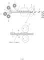
- FIG. 2 is a simplified front view (left drawing) of an apparatus for manufacturing a unit cell and a crosssectional view (right drawing) of each of an upper roller and a lower roller according to an embodiment of the present invention
- FIG. 3 is a view illustrating a state ⁇ A> when a long axis of the upper roller is perpendicular to the lower roller and a state ⁇ B> when a short axis of the upper roller is perpendicular to the lower roller.
- the apparatus for manufacturing the unit cell according to the present invention comprises a lower roller 10 and an upper roller 20.
- the upper roller 20 and the lower roller 10 are disposed to thermally fuse an upper separator 3a to a lower separator 3b before the upper separator 3a and the lower separator 3b are cut.
- the apparatus for manufacturing the unit cell which is provided in this embodiment, is provided in place of a pressing device 5 according to the related art or is additionally provided between the pressing device 5 and a cutter 8, in the separator 3 and the electrodes 1 and 2, the lower separator 3b and the upper separator 3a continuously move in a longitudinal direction and are provided in a state in which a positive electrode 1 and a negative electrode 2 are stacked between the lower separator 3b and the upper separator 3a and on the upper separator 3a, respectively, i.e., a state in which a ⁇ positive electrode/upper separator/negative electrode/lower separator' or a ⁇ negative electrode/upper separator/positive electrode/lower separator' are sequentially stacked from top to bottom.
- the lower roller 10 has a circular shape and is disposed under the lower separator 3b.
- the lower roller 10 is configured to be heated to a predetermined temperature through a heater (not shown) or the like.
- the lower roller 10 may be heated up to a range of 60°C to 110°C.
- the reason in which the temperature is limited to the range of 60°C to 250°C is because, when the temperature is less than 60°C, it is difficult to achieve efficient thermal fusion of the separator 3, and when the temperature exceeds 110°C, it is difficult to seal the separator 3 due to the melted (deformed or damaged) separator 3.
- the upper roller 20 is disposed to be vertically aligned with the lower roller 10 above the upper separator 3a and is configured to have an oval shape having a short axis and a long axis.
- the upper roller 20 may also be heated up to a range of 60°C to 110°C through an external heater (not shown).
- the upper roller 20 and the lower roller 10 axially rotate by motors M1 and M2, respectively, and are disposed to be maintained at a constant interval along a width direction (left and right direction in FIG. 2 ).
- a rotation speed of each of the motors M1 and M2 may be adjusted according to a transfer speed of each of the separators 3a and 3b, and the lower roller 10 and the upper roller 20 may rotate at the same time by using one motor.
- a portion at which the upper roller 20 is in contact with the upper separator 3a is made of a material having elasticity to prevent the separators 3a and 3b from being damaged.
- the upper roller 20 may comprise a core part 21 made of a material having relatively higher hardness and a surface part 22, which is coupled to cover a surface of the core part 21, made of relatively higher elasticity, and in contact with the upper separator 3a.
- the surface part 22 may be made of a rubber material or a silicone material having appropriate elasticity and may have shore hardness in a range of HS20 to HS40.
- the core part 21 is made of a metal material having higher hardness to support the surface part when the surface part is elastically deformed.
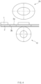
- FIG. 4 is a view illustrating a state in which the short axis of the upper roller 20 is perpendicular to the lower roller 10 when the electrode is disposed between the upper roller 20 and the lower roller 10
- FIG. 5 is a view illustrating a state in which the long axis of the upper roller 20 is perpendicular to the lower roller 10 and presses the separators 3a and 3b when only the separators 3a and 3b are disposed between the upper roller 20 and the lower roller 10.
- FIG. 4 is a view illustrating a state in which the short axis of the upper roller 20 is perpendicular to the lower roller 10 when the electrode is disposed between the upper roller 20 and the lower roller 10
- FIG. 5 is a view illustrating a state in which the long axis of the upper roller 20 is perpendicular to the lower roller 10 and presses the separators 3a and 3b when only the separators 3a and 3b are disposed between the upper roller 20 and the lower roller 10.
- FIG. 4 is a
- FIG. 6 is a view illustrating a state (i), in which the upper roller is heated, and the lower roller is not heated, a state (ii), in which the upper roller is not heated, and the lower roller is heated, and a state (iii), in which all of the upper roller and the lower roller are heated.
- the upper roller 20 and the lower roller 10 of the apparatus for manufacturing the unit cell which is provided in this embodiment, is installed before the separators 3 reach the cutter 8.
- the upper roller 20 is not in contact with the upper separator 3a, and after the electrodes 1 and 2 pass, and the upper roller 20 presses the upper separator 3a and the lower separator 3b to the surface of the lower roller 10.
- the upper roller 20 has a posture in which the short axis is oriented in a vertical direction (a direction in which the short axis is placed vertically). Thus, the upper roller 20 is not in contact the uppermost positive electrode 1.
- the separator 3 moves (in a right direction in FIG. 4 )
- the upper roller 20 also rotates (in a counterclockwise direction).
- the long axis of the upper roller 20 rotates to be disposed vertically (a direction in which the long axis is disposed vertically)
- the upper separator 3a starts to be pressed so as to be in contact with the lower separator 3b.
- At least one of the lower roller 10 rotating under the lower separator 3b and/or the upper roller 20 rotating above the upper separator 3a is in a state of being heated to a predetermined temperature.
- the lower separator 3b is thermally fused and sealed to the upper separator 3a.
- the upper roller 20 rotates in the counterclockwise direction based on FIG. 5 to rotate as illustrated in FIG. 4 , and then, when the next electrodes 1 and 2 are pass, the upper separator 3a and the lower separator 3b are thermally fused again in the same manner.
- the point at which the thermal fusion is achieved in this manner is cut by the cutter 8 illustrated in FIG. 1 to manufacture the unit cell 4.
- a pressure applied to the separator 3 may vary according to the material of the upper roller 20 and the interval between the upper roller 20 and the lower roller 10.
- a thickness of the separator made of a polyethylene (PE) material is 8 um to 20 ⁇ m
- a pressure applied to each of the lower separator and the upper separator by the lower roller 10 and the upper roller 20 is set in a range of 100 kg to 1,000 kg per unit area (1 cm 2 or 1 m 2 ).
- the lower roller 10 has a cylindrical shape. If the lower roller 10 is configured to efficiently transfer the heat of the heater 11 comprised therein to a surface of a housing 12, the lower roller 10 is not limited to a specific structure, but is preferably that straightness is 5/1000 or less, surface roughness is Ra 0.8 or less, and centrifugation is 8/1000 or less so that the portion to be sealed is evenly maintained in sealing quality.
- the upper roller 20 and the lower roller 10 may be configured to be heated in consideration of the material or thickness of each of the separators 3a and 3b, the interval between the electrodes, the heating temperature, and the like.
- only the upper roller 20 may be heated in a state in which the lower roller 10 is not heated. In this case, since heat is not unnecessarily transferred to the electrodes 1 and 2 (by the heated lower roller), thermal damage of the electrodes 1 and 2 may be prevented.
- the upper roller 20 may not be heated in a state in which the lower roller 10 is heated.
- the thermal fusion quality may be adjusted by adjusting the pressing force through the upper roller 20.
- the rollers may be configured in this manner.
- both the lower roller 10 and the upper roller 20 may be heated. In this case, heat may be uniformly transferred to the upper separator 3a and the lower separator 3b to improve thermal fusion efficiency.
- the apparatus for manufacturing the unit cell which is provided in this embodiment may be configured so that at least one or both of the upper roller 20 and the lower roller 10 is/are heated according to the required specification of the thermal fusion, the configurations of the upper roller 20 and the lower roller 10, the thickness or type of each of the separators 3a and 3b, and the like.
- a method for manufacturing a unit cell which is capable of manufacturing the unit cell using the above-described manufacturing apparatus is provided as a second embodiment.
- the manufacturing method provided in this embodiment comprises a process of laminating electrodes 1 and 2 and a separator 3 after stacking the electrodes 1 and 2 and the separator 3 in a predetermined order to provide the electrodes 1 and 2 and the separator 3 and a process of allowing the separator 3 to pass between the upper roller 2 and the lower roller 10.
- a lower separator 3b and an upper separator 3a continuously move in a longitudinal direction, and also, the electrodes 1 and 2 and the separators 3 are provided in a state in which the electrodes 1 and 2 are stacked between the lower separator 3b and the upper separator 3a and on the upper separators 3a, respectively.
- the electrodes 1 and 2 and the separator 3 are configured to pass between the lower roller 10 disposed under the lower separator 3b and the upper roller 20 disposed to be vertically aligned with the lower roller 10 above the upper separator 3a and having an oval shape with a short axis and a long axis.
- the upper roller 20 when the electrodes 1 and 2 pass while the upper roller 20 rotates, the upper roller 20 is not in contact with the upper separator 3a and the positive electrode 1 stacked at the uppermost layer, and after the electrodes 1 and 2 pass, the upper roller 20 presses the upper separator 3a and the lower separator 3b to a surface of the lower roller 10 so as to be thermally fused.
- the upper roller 20 is made of a material having elasticity so that, when the upper separator 3a is pressed, the upper separator 3a is pressed by the elastic force of the material of the upper roller 20.
- at least one of the upper roller 20 or the lower roller 10 is heated to perform the thermal fusion at points at which the separators 3a and 3b are pressed.
- the present invention having the configuration as described above comprises the upper roller 20 having an oval shape and the lower roller 10 having a circular shape, and at least one of the upper roller 20 and the lower roller 10 is heated to a predetermined temperature so that the long axis of the upper roller 20 presses the separators 3a and 3b to bond (thermally fuse) the upper separator 3a to the lower separator 3b.
- the separators 3a and 3b are fixed after the cutting so as to prevent from being folded.
- the portion at which the upper roller 20 and the separator 3 are in contact with each other may be made of the material having the elasticity to prevent the separator 3 from being damaged when being pressed.
Landscapes
- Chemical & Material Sciences (AREA)
- Chemical Kinetics & Catalysis (AREA)
- Electrochemistry (AREA)
- General Chemical & Material Sciences (AREA)
- Engineering & Computer Science (AREA)
- Manufacturing & Machinery (AREA)
- Secondary Cells (AREA)
- Cell Separators (AREA)
Abstract
Description
- The present application claims the benefit of the priority of
Korean Patent Application Nos. 10-2020-0182655, filed on December 23, 2020 10-2021-0184173, filed on December 21, 2021 - The present invention relates to a method and apparatus for manufacturing a unit cell, and more particularly, to a method and apparatus for manufacturing a unit cell, in which a portion to be cut at a lower separator and an upper separator is previously bonded (sealed) before cutting the lower separator and the upper separator to prevent a separator from being folded.
- Unlike a primary battery, since a secondary battery may be rechargeable and also be miniaturized and large capacity, a lot of research and development has been carried out in recent years. Also, as technology development and demands for mobile devices increase, the demands for secondary batteries as energy sources are rapidly increasing.
- Such a secondary battery is configured so that an electrode assembly and an electrolyte are embedded in a case (for example, a pouch, a can, and the like). The electrode assembly mounted in the case is repeatedly chargeable and dischargeable because of a structure in which a positive electrode/a separator/a negative electrode are stacked. The electrode assembly is manufactured in various manners. However, generally, the electrode assembly may be manufactured in a manner in which, after a unit cell 4 is prepared in advance, a plurality of unit cells 4 are stacked to manufacture the electrode assembly.
- That is, referring to
FIG. 1 , which illustrates a state in which a unit cell is manufactured according to the related art, in a method for manufacturing the unit cell 4 according to the related art, apositive electrode 1, anupper separator 3a, anegative electrode 2, and alower separator 3b are continuously unwound to be supplied in a state in which each of thepositive electrode 1, theupper separator 3a, thenegative electrode 2, and thelower separator 3b is wound in the form of a roll (however, stacking positions of the positive electrode and the negative electrode may be changed). - The separators 3 (3a and 3b) are continuously supplied without disconnection, the
negative electrode 2 is supplied between theupper separator 3a and thelower separator 3b, and thepositive electrode 1 is supplied onto theupper separator 3a. - Here, the separators 3 are continuously supplied without being cut. On the other hand, the
positive electrode 1 and thenegative electrode 2 are provided in a state of being cut to predetermined sizes byrespective cutters positive electrode 1 and thenegative electrode 2 are paired to be aligned and stacked vertically with theupper separator 3a therebetween and are disposed to be spaced a predetermined distance from thepositive electrode 1 and thenegative electrode 2 adjacent to each other. - That is, the separators 3 are continuously connected, and the
negative electrode 2 and thepositive electrode 1 pass through alaminating device 9 in a state of being spaced a predetermined distance from thenegative electrode 2 and thepositive electrode 1, which are adjacent to the above negative and positive electrodes. In thelaminating device 9, heat and a pressure are applied so that thenegative electrode 2 and thepositive electrode 1 are bonded to contact points with the separators 3. - After the
positive electrode 1 and thenegative electrode 2 pass through thelaminating device 9 in a state of being bonded to the separator 3, thepositive electrode 1 and thenegative electrode 2 pass through apressing device 5 constituted by cylindrical rollers, which are disposed vertically in pairs, so as to be additionally pressed. - Then, the separator 3 is cut between the adjacent
positive electrode 1 and thepositive electrode 1 by acutter 8 and then is provided to individual unit cells 4. - That is, after the
electrodes device 9 and thepressing device 5, the cutting of the separators 3 are performed between the adjacent electrodes so that the separators 3 are manufactured into individual unit cells 4. - However, the
cutter 8 has a structure in which the pressure is applied vertically to cut the separators 3. Thus, when any one of theseparators separators - Also, after the unit cells 4 are manufactured, since the plurality of unit cells 4 are stacked to be manufactured as an electrode assembly, the folding of the separators 3 occurs, and thus, when a portion of the
negative electrode 2 or thepositive electrode 1 is exposed, short circuit occurs inside the electrode assembly. - That is, the bonding is performed at points at which the separator 3 and the
electrodes upper separator 3a and thelower separator 3b are not bonded to each other, and thus, when the cutting is performed by thecutter 8, or after the cutting is performed, there is a problem in that the separator may not be fixed, but be folded. - Therefore, an object of the present invention is to provide a method and apparatus for manufacturing a unit cell, in which an upper separator and a lower separator are bonded (sealed) before the separators are cut (before points of the separators, at which the separators are to be cut, reach a cutter 8) to prevent the upper separator and the lower separator from being folded when the separators are cut.
- An apparatus for manufacturing a unit cell, which cuts a lower separator and an upper separator between electrodes (a positive electrode and a negative electrode) adjacent to each other (in a longitudinal direction of the separator) in a process of manufacturing the unit cell provided in a state (i.e., a stacked state in the order of the `positive electrode/upper separator/negative electrode/lower separator' or the `negative electrode/upper separator/positive electrode/lower separator' from top to bottom), in which the lower separator and the upper separator continuously move in a longitudinal direction, and the electrodes are stacked between the lower separator and the upper separator and on the upper separator, respectively, according to the present invention for achieving the above object comprises: a lower roller disposed under the lower separator; and an upper roller which is disposed above the upper separator so as to be vertically aligned with the lower roller and has an oval shape with a long axis and a short axis, wherein, when the electrodes pass while the upper roller rotates, the upper roller is not in contact with the upper separator, and after the electrodes pass, the upper roller presses the upper separator and the lower separator to a surface of the lower roller, and at least one of the lower roller or the upper roller is heated to a predetermined temperature to thermally fuse points at which the upper separator and the lower separator are pressed.
- The upper roller and the lower roller may be disposed to thermally fuse the upper separator and the lower separator before the upper separator and the lower separator are cut.
- A portion at which the upper roller is in contact with the separator may be made of a material having elasticity.
- The upper roller may comprise: a core part made of a material having relatively higher hardness; and a surface part, which is coupled to cover a surface of the core part, made of relatively higher elasticity, and in contact with the upper separator.
- The surface part may be made of material having shore hardness in a range of HS20 to HS40.
- Any one or more of the lower roller and the upper roller may be heated up to a range of 60°C to 110°C.
- When the lower roller and the upper roller press the lower separator and the upper separator, a pressure applied between the lower roller and the upper roller may be set in a range of 100 kg to 1,000 kg.
- The lower roller may be heated, and the upper roller may be not heated. The lower roller may not be heated, and the upper roller may be heated. Both the lower roller and the upper roller may be heated.
- Furthermore, a method for manufacturing a unit cell, in which electrodes are stacked between a lower separator and an upper separator and on the upper separator, respectively, which is provided is the present invention, comprises: a process of providing the electrodes and the separators in a state in which the lower separator and the upper separator continuously move in a longitudinal direction, and the electrodes are stacked between the lower separator and the upper separator and on the upper separator, respectively; and a process of allowing the electrodes and the separator to pass between the lower roller disposed under the lower separator and the upper roller disposed to be vertically aligned with the lower roller above the upper separator and having an oval shape with a short axis and a long axis, wherein, when the electrodes pass while the upper roller rotates, the upper roller is not in contact with the upper separator, and after the electrodes pass, the upper roller presses the upper separator and the lower separator to a surface of the lower roller, and at least one of the lower roller or the upper roller is heated to a predetermined temperature to thermally fuse points at which the upper separator and the lower separator are pressed.
- The upper roller and the lower roller may be disposed to thermally fuse the upper separator and the lower separator before the upper separator and the lower separator are cut.
- The upper roller may be made of a material having elasticity so that, when the upper separator is pressed, the upper separator is pressed by elastic force of the material of the upper roller.
- The present invention having the configuration as described above may comprise the upper roller having the oval shape and the lower roller having the circular shape. Here, at least one or more of the upper roller and the lower roller may be heated at the predetermined temperature, and the long axis of the upper roller may press the separators to bond (thermally fuse) the upper separator to the lower separator. Therefore, after the cutting is performed, the folding of the separator may be prevented.
- The portion at which the upper roller and the separator are in contact with each other may be made of the material having the elasticity to prevent the separator from being damaged when being pressed.
-
-
FIG. 1 is a schematic view illustrating a state in which a unit cell is manufactured through a method according to a related art. -
FIG. 2 is a simplified front view (left drawing) of an apparatus for manufacturing a unit cell and a crosssectional view (right drawing) of each of an upper roller and a lower roller according to an embodiment of the present invention. -
FIG. 3 is a view illustrating a state <A> when a long axis of the upper roller is perpendicular to the lower roller and a state <B> when a short axis of the upper roller is perpendicular to the lower roller. -
FIG. 4 is a view illustrating a state in which the short axis of the upper roller is perpendicular to the lower roller when an electrode is disposed between the upper roller and the lower roller. -
FIG. 5 is a view illustrating a state in which the long axis of the upper roller is perpendicular to the lower roller and presses separators when only the separators are disposed between the upper roller and the lower roller. -
FIG. 6 is a view illustrating a state (i), in which the upper roller is heated, and the lower roller is not heated, a state (ii), in which the upper roller is not heated, and the lower roller is heated, and a state (iii), in which all of the upper roller and the lower roller are heated. - Hereinafter, preferred embodiments of the present invention will be described in detail with reference to the accompanying drawings in such a manner that the technical idea of the present invention may easily be carried out by a person with ordinary skill in the art to which the invention pertains. The present invention may, however, be embodied in different forms and should not be construed as limited to the embodiments set forth herein.
- In order to clearly describe the present invention, parts irrelevant to the description are omitted, and the same reference numerals are assigned to the same or similar components throughout the specification.
- Also, terms or words used in this specification and claims should not be restrictively interpreted as ordinary meanings or dictionary-based meanings, but should be interpreted as meanings and concepts conforming to the scope of the present invention on the basis of the principle that an inventor can properly define the concept of a term to describe and explain his or her invention in the best ways.
- The present invention relates to a method and apparatus for manufacturing a unit cell 4 in which
electrodes lower separator 3b and anupper separator 3a and on theupper separator 3a. Hereinafter, embodiments according to the present invention will be described in more detail with reference to the accompanying drawings. - The present invention provides a method for manufacturing a unit cell according to a first embodiment. The apparatus for manufacturing the unit cell provided in this embodiment may be added between a
pressing device 5 and acutter 8 in a process illustrated inFIG. 1 or may be installed instead of thepressing device 5. -
FIG. 2 is a simplified front view (left drawing) of an apparatus for manufacturing a unit cell and a crosssectional view (right drawing) of each of an upper roller and a lower roller according to an embodiment of the present invention, andFIG. 3 is a view illustrating a state <A> when a long axis of the upper roller is perpendicular to the lower roller and a state <B> when a short axis of the upper roller is perpendicular to the lower roller. - As illustrated in the drawings, the apparatus for manufacturing the unit cell according to the present invention comprises a
lower roller 10 and anupper roller 20. Theupper roller 20 and thelower roller 10 are disposed to thermally fuse anupper separator 3a to alower separator 3b before theupper separator 3a and thelower separator 3b are cut. - As the apparatus for manufacturing the unit cell, which is provided in this embodiment, is provided in place of a
pressing device 5 according to the related art or is additionally provided between thepressing device 5 and acutter 8, in the separator 3 and theelectrodes lower separator 3b and theupper separator 3a continuously move in a longitudinal direction and are provided in a state in which apositive electrode 1 and anegative electrode 2 are stacked between thelower separator 3b and theupper separator 3a and on theupper separator 3a, respectively, i.e., a state in which a `positive electrode/upper separator/negative electrode/lower separator' or a `negative electrode/upper separator/positive electrode/lower separator' are sequentially stacked from top to bottom. - The
lower roller 10 has a circular shape and is disposed under thelower separator 3b. In addition, thelower roller 10 is configured to be heated to a predetermined temperature through a heater (not shown) or the like. - In this embodiment, the
lower roller 10 may be heated up to a range of 60°C to 110°C. The reason in which the temperature is limited to the range of 60°C to 250°C is because, when the temperature is less than 60°C, it is difficult to achieve efficient thermal fusion of the separator 3, and when the temperature exceeds 110°C, it is difficult to seal the separator 3 due to the melted (deformed or damaged) separator 3. - In addition, the
upper roller 20 is disposed to be vertically aligned with thelower roller 10 above theupper separator 3a and is configured to have an oval shape having a short axis and a long axis. Theupper roller 20 may also be heated up to a range of 60°C to 110°C through an external heater (not shown). - Thus, as illustrated in
FIG. 3 , when the long axis is erected vertically, an interval between theupper roller 20 and thelower roller 10 is relatively small, and when the short axis is erected vertically, an interval between theupper roller 20 and thelower roller 10 is relatively large. That is, the interval between theupper roller 20 and thelower roller 10 varies according to a rotational position of theupper roller 20. - As illustrated in
FIG. 2 , theupper roller 20 and thelower roller 10 axially rotate by motors M1 and M2, respectively, and are disposed to be maintained at a constant interval along a width direction (left and right direction inFIG. 2 ). A rotation speed of each of the motors M1 and M2 may be adjusted according to a transfer speed of each of theseparators lower roller 10 and theupper roller 20 may rotate at the same time by using one motor. - When the
upper roller 20 is in contact with theupper separator 3a, a portion at which theupper roller 20 is in contact with theupper separator 3a is made of a material having elasticity to prevent theseparators - That is, the
upper roller 20 may comprise acore part 21 made of a material having relatively higher hardness and asurface part 22, which is coupled to cover a surface of thecore part 21, made of relatively higher elasticity, and in contact with theupper separator 3a. - The
surface part 22 may be made of a rubber material or a silicone material having appropriate elasticity and may have shore hardness in a range of HS20 to HS40. In addition, thecore part 21 is made of a metal material having higher hardness to support the surface part when the surface part is elastically deformed. -
FIG. 4 is a view illustrating a state in which the short axis of theupper roller 20 is perpendicular to thelower roller 10 when the electrode is disposed between theupper roller 20 and thelower roller 10, andFIG. 5 is a view illustrating a state in which the long axis of theupper roller 20 is perpendicular to thelower roller 10 and presses theseparators separators upper roller 20 and thelower roller 10. Also,FIG. 6 is a view illustrating a state (i), in which the upper roller is heated, and the lower roller is not heated, a state (ii), in which the upper roller is not heated, and the lower roller is heated, and a state (iii), in which all of the upper roller and the lower roller are heated. - Referring to
FIGS. 4 and5 , theupper roller 20 and thelower roller 10 of the apparatus for manufacturing the unit cell, which is provided in this embodiment, is installed before the separators 3 reach thecutter 8. When theelectrodes upper roller 20, theupper roller 20 is not in contact with theupper separator 3a, and after theelectrodes upper roller 20 presses theupper separator 3a and thelower separator 3b to the surface of thelower roller 10. - That is, while the
electrodes upper roller 20, theupper roller 20 has a posture in which the short axis is oriented in a vertical direction (a direction in which the short axis is placed vertically). Thus, theupper roller 20 is not in contact the uppermostpositive electrode 1. In addition, when the separator 3 moves (in a right direction inFIG. 4 ), theupper roller 20 also rotates (in a counterclockwise direction). Thus, when the long axis of theupper roller 20 rotates to be disposed vertically (a direction in which the long axis is disposed vertically), theupper separator 3a starts to be pressed so as to be in contact with thelower separator 3b. - Here, at least one of the
lower roller 10 rotating under thelower separator 3b and/or theupper roller 20 rotating above theupper separator 3a is in a state of being heated to a predetermined temperature. In addition, since theupper separator 3a and thelower separator 3b are pressed to the surface of thelower roller 10, thelower separator 3b is thermally fused and sealed to theupper separator 3a. - In addition, when the thermal fusion of the
separators upper roller 20 rotates in the counterclockwise direction based onFIG. 5 to rotate as illustrated inFIG. 4 , and then, when thenext electrodes upper separator 3a and thelower separator 3b are thermally fused again in the same manner. - The point at which the thermal fusion is achieved in this manner is cut by the
cutter 8 illustrated inFIG. 1 to manufacture the unit cell 4. - A pressure applied to the separator 3 may vary according to the material of the
upper roller 20 and the interval between theupper roller 20 and thelower roller 10. Here, when a thickness of the separator made of a polyethylene (PE) material is 8 um to 20 µm, it is preferable that a pressure applied to each of the lower separator and the upper separator by thelower roller 10 and theupper roller 20 is set in a range of 100 kg to 1,000 kg per unit area (1 cm2 or 1 m2). - Furthermore, the
lower roller 10 has a cylindrical shape. If thelower roller 10 is configured to efficiently transfer the heat of theheater 11 comprised therein to a surface of ahousing 12, thelower roller 10 is not limited to a specific structure, but is preferably that straightness is 5/1000 or less, surface roughness is Ra 0.8 or less, and centrifugation is 8/1000 or less so that the portion to be sealed is evenly maintained in sealing quality. - In the method for manufacturing the unit cell according to the present invention, the
upper roller 20 and thelower roller 10 may be configured to be heated in consideration of the material or thickness of each of theseparators - That is, as illustrated in
FIG. 6 , i.e., as illustrated in the left drawing (i), only theupper roller 20 may be heated in a state in which thelower roller 10 is not heated. In this case, since heat is not unnecessarily transferred to theelectrodes 1 and 2 (by the heated lower roller), thermal damage of theelectrodes - In addition, as illustrated in the middle drawing (ii), the
upper roller 20 may not be heated in a state in which thelower roller 10 is heated. In this case, since thelower separator 3b is heated as a whole along the longitudinal direction, the thermal fusion quality may be adjusted by adjusting the pressing force through theupper roller 20. Particularly, when the heat transfer through theupper roller 20 is difficult according to the material of the surface part, the rollers may be configured in this manner. - In addition, as illustrated in the right drawing (iii), both the
lower roller 10 and theupper roller 20 may be heated. In this case, heat may be uniformly transferred to theupper separator 3a and thelower separator 3b to improve thermal fusion efficiency. - Therefore, the apparatus for manufacturing the unit cell, which is provided in this embodiment may be configured so that at least one or both of the
upper roller 20 and thelower roller 10 is/are heated according to the required specification of the thermal fusion, the configurations of theupper roller 20 and thelower roller 10, the thickness or type of each of theseparators - In the present invention, a method for manufacturing a unit cell, which is capable of manufacturing the unit cell using the above-described manufacturing apparatus is provided as a second embodiment.
- The manufacturing method provided in this embodiment comprises a process of
laminating electrodes electrodes electrodes upper roller 2 and thelower roller 10. - That is, in the process of providing the
electrodes lower separator 3b and anupper separator 3a continuously move in a longitudinal direction, and also, theelectrodes electrodes lower separator 3b and theupper separator 3a and on theupper separators 3a, respectively. - In addition, in the process of allowing the separator 3 to pass between the
upper roller 20 and thelower roller 10, theelectrodes lower roller 10 disposed under thelower separator 3b and theupper roller 20 disposed to be vertically aligned with thelower roller 10 above theupper separator 3a and having an oval shape with a short axis and a long axis. - Here, when the
electrodes upper roller 20 rotates, theupper roller 20 is not in contact with theupper separator 3a and thepositive electrode 1 stacked at the uppermost layer, and after theelectrodes upper roller 20 presses theupper separator 3a and thelower separator 3b to a surface of thelower roller 10 so as to be thermally fused. Here, theupper roller 20 is made of a material having elasticity so that, when theupper separator 3a is pressed, theupper separator 3a is pressed by the elastic force of the material of theupper roller 20. Here, at least one of theupper roller 20 or thelower roller 10 is heated to perform the thermal fusion at points at which theseparators - The points at which the thermal fusion is achieved through the
upper roller 20 and thelower roller 10 move to the next positions to be cut by acutter 8. - The present invention having the configuration as described above comprises the
upper roller 20 having an oval shape and thelower roller 10 having a circular shape, and at least one of theupper roller 20 and thelower roller 10 is heated to a predetermined temperature so that the long axis of theupper roller 20 presses theseparators upper separator 3a to thelower separator 3b. Thus, since the sealing of the cut points are performed, theseparators - The portion at which the
upper roller 20 and the separator 3 are in contact with each other may be made of the material having the elasticity to prevent the separator 3 from being damaged when being pressed. - While the embodiments of the present invention have been described with reference to the specific embodiments, it will be apparent to those skilled in the art that various changes and modifications may be made without departing from the spirit and scope of the invention as defined in the following claims.
-
- 1: Positive electrode
- 2: Negative electrode
- 3: Separator (3a: upper separator, 3b: lower separator)
- 10: Lower roller
- 11: Heater
- 12: Housing
- 20: Upper roller
- 21: Core part
- 22: Surface part
Claims (13)
- An apparatus for manufacturing a unit cell, which cuts a lower separator and an upper separator between electrodes adjacent to each other in a process of manufacturing the unit cell provided in a state, in which the lower separator and the upper separator continuously move in a longitudinal direction, and the electrodes are stacked between the lower separator and the upper separator and on the upper separator, respectively, the apparatus comprising:a lower roller disposed under the lower separator; andan upper roller which is disposed above the upper separator so as to be vertically aligned with the lower roller and has an oval shape with a long axis and a short axis,wherein, when the electrodes pass while the upper roller rotates, the upper roller is not in contact with the upper separator, and after the electrodes pass, the upper roller presses the upper separator and the lower separator to a surface of the lower roller, andat least one of the lower roller or the upper roller is heated to a predetermined temperature to thermally fuse points at which the upper separator and the lower separator are pressed.
- The apparatus of claim 1, wherein the upper roller and the lower roller are disposed to thermally fuse the upper separator and the lower separator before the upper separator and the lower separator are cut.
- The apparatus of claim 1, wherein a portion at which the upper roller is in contact with the separator is made of a material having elasticity.
- The apparatus of claim 3, wherein the upper roller comprises:a core part made of a material having relatively higher hardness; anda surface part, which is coupled to cover a surface of the core part, made of relatively higher elasticity, and in contact with the upper separator.
- The apparatus of claim 4, wherein the surface part is made of material having shore hardness in a range of HS20 to HS40.
- The apparatus of claim 1, wherein any one or more of the lower roller and the upper roller are heated up to a range of 60°C to 110°C.
- The apparatus of claim 4, wherein, when the lower roller and the upper roller press the lower separator and the upper separator, a pressure applied between the lower roller and the upper roller is set in a range of 100 kg to 1,000 kg.
- The apparatus of claim 1, wherein the lower roller is heated, and the upper roller is not heated.
- The apparatus of claim 1, wherein the lower roller is not heated, and the upper roller is heated.
- The apparatus of claim 1, wherein both the lower roller and the upper roller are heated.
- A method for manufacturing a unit cell, in which electrodes are stacked between a lower separator and an upper separator and on the upper separator, respectively, the method comprising:a process of providing the electrodes and the separators in a state in which the lower separator and the upper separator continuously move in a longitudinal direction, and the electrodes are stacked between the lower separator and the upper separator and on the upper separator, respectively; anda process of allowing the electrodes and the separator to pass between the lower roller disposed under the lower separator and the upper roller disposed to be vertically aligned with the lower roller above the upper separator and having an oval shape with a short axis and a long axis,wherein, when the electrodes pass while the upper roller rotates, the upper roller is not in contact with the upper separator, and after the electrodes pass, the upper roller presses the upper separator and the lower separator to a surface of the lower roller, andat least one of the lower roller or the upper roller is heated to a predetermined temperature to thermally fuse points at which the upper separator and the lower separator are pressed.
- The method of claim 11, wherein the upper roller and the lower roller are disposed to thermally fuse the upper separator and the lower separator before the upper separator and the lower separator are cut.
- The method of claim 11, wherein the upper roller is made of a material having elasticity so that, when the upper separator is pressed, the upper separator is pressed by elastic force of the material of the upper roller.
Applications Claiming Priority (3)
| Application Number | Priority Date | Filing Date | Title |
|---|---|---|---|
| KR20200182655 | 2020-12-23 | ||
| KR1020210184173A KR20220091399A (en) | 2020-12-23 | 2021-12-21 | Manufacturing method and apparatus for unit cell |
| PCT/KR2021/019761 WO2022139519A1 (en) | 2020-12-23 | 2021-12-23 | Unit cell preparation method and apparatus |
Publications (3)
| Publication Number | Publication Date |
|---|---|
| EP4270567A1 true EP4270567A1 (en) | 2023-11-01 |
| EP4270567A4 EP4270567A4 (en) | 2024-10-23 |
| EP4270567B1 EP4270567B1 (en) | 2025-11-26 |
Family
ID=82159684
Family Applications (1)
| Application Number | Title | Priority Date | Filing Date |
|---|---|---|---|
| EP21911584.7A Active EP4270567B1 (en) | 2020-12-23 | 2021-12-23 | Unit cell preparation method and apparatus |
Country Status (5)
| Country | Link |
|---|---|
| US (1) | US20230387447A1 (en) |
| EP (1) | EP4270567B1 (en) |
| CN (1) | CN116325257A (en) |
| ES (1) | ES3065520T3 (en) |
| WO (1) | WO2022139519A1 (en) |
Families Citing this family (1)
| Publication number | Priority date | Publication date | Assignee | Title |
|---|---|---|---|---|
| KR102755154B1 (en) * | 2021-01-28 | 2025-01-21 | 주식회사 엘지에너지솔루션 | Separator Adhesive Device |
Family Cites Families (11)
| Publication number | Priority date | Publication date | Assignee | Title |
|---|---|---|---|---|
| GB907052A (en) * | 1960-02-18 | 1962-10-03 | London Rubber Company Ltd | Improvements in or relating to packaging machines |
| KR200314731Y1 (en) * | 2003-03-11 | 2003-05-27 | 연일화섬공업(주) | fusion device of waterproof sheet |
| WO2013031213A1 (en) * | 2011-08-29 | 2013-03-07 | パナソニック株式会社 | Electrode plate for non-aqueous secondary battery and non-aqueous secondary battery using same |
| KR101749148B1 (en) * | 2014-10-23 | 2017-06-20 | 주식회사 엘지화학 | Lamination Device Using High-frequency Induction Heating and Secondary Battery Manufactured Using the Same |
| JP6290071B2 (en) * | 2014-11-28 | 2018-03-07 | プライムアースEvエナジー株式会社 | Battery electrode plate manufacturing apparatus and battery electrode plate manufacturing method |
| KR101625602B1 (en) * | 2015-10-28 | 2016-05-30 | 주식회사 케이엠지 | Method for manufacturing secondary battery using transferring |
| JP6906764B2 (en) * | 2017-08-01 | 2021-07-21 | 株式会社豊田自動織機 | Electrode manufacturing equipment with separator |
| KR102442472B1 (en) * | 2017-11-17 | 2022-09-14 | 주식회사 엘지에너지솔루션 | Lamination apparatus and method for secondary battery |
| JP6902731B2 (en) * | 2018-02-05 | 2021-07-14 | パナソニックIpマネジメント株式会社 | Battery manufacturing method |
| CN108878988B (en) * | 2018-06-29 | 2024-04-09 | 深圳吉阳智能科技有限公司 | Lamination area, lamination area preparation equipment and lamination equipment |
| CN211838756U (en) * | 2020-01-06 | 2020-11-03 | 广东桑泰科技有限公司 | A release paper gluing device for lamination production |
-
2021
- 2021-12-23 CN CN202180067371.XA patent/CN116325257A/en active Pending
- 2021-12-23 ES ES21911584T patent/ES3065520T3/en active Active
- 2021-12-23 WO PCT/KR2021/019761 patent/WO2022139519A1/en not_active Ceased
- 2021-12-23 EP EP21911584.7A patent/EP4270567B1/en active Active
- 2021-12-23 US US18/032,734 patent/US20230387447A1/en active Pending
Also Published As
| Publication number | Publication date |
|---|---|
| EP4270567A4 (en) | 2024-10-23 |
| WO2022139519A1 (en) | 2022-06-30 |
| US20230387447A1 (en) | 2023-11-30 |
| ES3065520T3 (en) | 2026-05-06 |
| EP4270567B1 (en) | 2025-11-26 |
| CN116325257A (en) | 2023-06-23 |
Similar Documents
| Publication | Publication Date | Title |
|---|---|---|
| JP7368052B2 (en) | Cell manufacturing equipment and method | |
| US20190237797A1 (en) | Stacking device for secondary battery, stacking method using same, and secondary battery obtained thereby | |
| KR102025288B1 (en) | Taping Machine for Bonding Insulative Tape to Peripheral Sealing Part of Battery Cell | |
| EP3583640B1 (en) | Method for manufacturing electric vehicle battery cells with polymer frame support | |
| EP3416225B1 (en) | Electrode assembly and manufacturing method therefor | |
| US11799173B2 (en) | Secondary battery and manufacturing method thereof | |
| EP3955354A1 (en) | Electrode assembly manufacturing device, electrode assembly manufactured thereby and secondary battery | |
| US12492095B2 (en) | Apparatus for manufacturing electrode assembly, electrode assembly manufactured therethrough, and secondary battery | |
| JP4786342B2 (en) | Apparatus and method for stacking polymer battery combination | |
| US11424474B2 (en) | Secondary battery, and apparatus and method for manufacturing the same | |
| CN105406101B (en) | Rolling equipment and rolling method for secondary battery | |
| KR101748466B1 (en) | Cutting apparatus for secondary battery | |
| EP4270567B1 (en) | Unit cell preparation method and apparatus | |
| KR20220091399A (en) | Manufacturing method and apparatus for unit cell | |
| EP4270564A1 (en) | Method and apparatus for manufacturing unit cell | |
| JPH11154534A (en) | Lithium ion secondary battery element | |
| KR102914055B1 (en) | The Apparatus And The Method For Manufacturing Unit Cell | |
| EP4333146B1 (en) | Electrode assembly manufacturing apparatus for preventing separator folding and electrode assembly manufactured using the same | |
| KR20220010413A (en) | Separator sealing device and unit cell manufacturing device using the same | |
| KR20200056191A (en) | Manufacturing method and manufacturing apparatus for electrode assembly | |
| KR20220091357A (en) | Manufacturing method and apparatus for unit cell | |
| KR100898069B1 (en) | Electrode Assembly of Lithium Ion Battery and Pouch Type Battery Using the Same | |
| EP4184630B1 (en) | Separator sealing device and unit cell manufacturing device using same | |
| EP4685893A1 (en) | Electrode assembly manufacturing apparatus and electrode assembly manufacturing method | |
| US20230282869A1 (en) | Method And Apparatus For Manufacturing Unit Cell |
Legal Events
| Date | Code | Title | Description |
|---|---|---|---|
| STAA | Information on the status of an ep patent application or granted ep patent |
Free format text: STATUS: THE INTERNATIONAL PUBLICATION HAS BEEN MADE |
|
| PUAI | Public reference made under article 153(3) epc to a published international application that has entered the european phase |
Free format text: ORIGINAL CODE: 0009012 |
|
| STAA | Information on the status of an ep patent application or granted ep patent |
Free format text: STATUS: REQUEST FOR EXAMINATION WAS MADE |
|
| 17P | Request for examination filed |
Effective date: 20230330 |
|
| AK | Designated contracting states |
Kind code of ref document: A1 Designated state(s): AL AT BE BG CH CY CZ DE DK EE ES FI FR GB GR HR HU IE IS IT LI LT LU LV MC MK MT NL NO PL PT RO RS SE SI SK SM TR |
|
| DAV | Request for validation of the european patent (deleted) | ||
| DAX | Request for extension of the european patent (deleted) | ||
| A4 | Supplementary search report drawn up and despatched |
Effective date: 20240923 |
|
| RIC1 | Information provided on ipc code assigned before grant |
Ipc: H01M 50/46 20210101ALI20240917BHEP Ipc: H01M 10/04 20060101AFI20240917BHEP |
|
| GRAP | Despatch of communication of intention to grant a patent |
Free format text: ORIGINAL CODE: EPIDOSNIGR1 |
|
| STAA | Information on the status of an ep patent application or granted ep patent |
Free format text: STATUS: GRANT OF PATENT IS INTENDED |
|
| INTG | Intention to grant announced |
Effective date: 20250623 |
|
| GRAS | Grant fee paid |
Free format text: ORIGINAL CODE: EPIDOSNIGR3 |
|
| GRAA | (expected) grant |
Free format text: ORIGINAL CODE: 0009210 |
|
| STAA | Information on the status of an ep patent application or granted ep patent |
Free format text: STATUS: THE PATENT HAS BEEN GRANTED |
|
| P01 | Opt-out of the competence of the unified patent court (upc) registered |
Free format text: CASE NUMBER: UPC_APP_7781_4270567/2025 Effective date: 20250924 |
|
| AK | Designated contracting states |
Kind code of ref document: B1 Designated state(s): AL AT BE BG CH CY CZ DE DK EE ES FI FR GB GR HR HU IE IS IT LI LT LU LV MC MK MT NL NO PL PT RO RS SE SI SK SM TR |
|
| REG | Reference to a national code |
Ref country code: CH Ref legal event code: F10 Free format text: ST27 STATUS EVENT CODE: U-0-0-F10-F00 (AS PROVIDED BY THE NATIONAL OFFICE) Effective date: 20251126 Ref country code: GB Ref legal event code: FG4D |
|
| REG | Reference to a national code |
Ref country code: DE Ref legal event code: R096 Ref document number: 602021043365 Country of ref document: DE |
|
| REG | Reference to a national code |
Ref country code: IE Ref legal event code: FG4D |
|
| PGFP | Annual fee paid to national office [announced via postgrant information from national office to epo] |
Ref country code: GB Payment date: 20251222 Year of fee payment: 5 |
|
| PGFP | Annual fee paid to national office [announced via postgrant information from national office to epo] |
Ref country code: AT Payment date: 20260113 Year of fee payment: 5 |
|
| PGFP | Annual fee paid to national office [announced via postgrant information from national office to epo] |
Ref country code: FR Payment date: 20251223 Year of fee payment: 5 |
|
| PGFP | Annual fee paid to national office [announced via postgrant information from national office to epo] |
Ref country code: BE Payment date: 20251229 Year of fee payment: 5 |
|
| REG | Reference to a national code |
Ref country code: NL Ref legal event code: MP Effective date: 20251126 |
|
| PGFP | Annual fee paid to national office [announced via postgrant information from national office to epo] |
Ref country code: ES Payment date: 20260122 Year of fee payment: 5 |
|
| REG | Reference to a national code |
Ref country code: LT Ref legal event code: MG9D |
|
| PG25 | Lapsed in a contracting state [announced via postgrant information from national office to epo] |
Ref country code: NO Free format text: LAPSE BECAUSE OF FAILURE TO SUBMIT A TRANSLATION OF THE DESCRIPTION OR TO PAY THE FEE WITHIN THE PRESCRIBED TIME-LIMIT Effective date: 20260226 |
|
| PGFP | Annual fee paid to national office [announced via postgrant information from national office to epo] |
Ref country code: DE Payment date: 20251222 Year of fee payment: 5 |
|
| PG25 | Lapsed in a contracting state [announced via postgrant information from national office to epo] |
Ref country code: HR Free format text: LAPSE BECAUSE OF FAILURE TO SUBMIT A TRANSLATION OF THE DESCRIPTION OR TO PAY THE FEE WITHIN THE PRESCRIBED TIME-LIMIT Effective date: 20251126 Ref country code: FI Free format text: LAPSE BECAUSE OF FAILURE TO SUBMIT A TRANSLATION OF THE DESCRIPTION OR TO PAY THE FEE WITHIN THE PRESCRIBED TIME-LIMIT Effective date: 20251126 Ref country code: AT Free format text: LAPSE BECAUSE OF FAILURE TO SUBMIT A TRANSLATION OF THE DESCRIPTION OR TO PAY THE FEE WITHIN THE PRESCRIBED TIME-LIMIT Effective date: 20251126 |
|
| REG | Reference to a national code |
Ref country code: AT Ref legal event code: MK05 Ref document number: 1862005 Country of ref document: AT Kind code of ref document: T Effective date: 20251126 |
|
| PG25 | Lapsed in a contracting state [announced via postgrant information from national office to epo] |
Ref country code: NL Free format text: LAPSE BECAUSE OF FAILURE TO SUBMIT A TRANSLATION OF THE DESCRIPTION OR TO PAY THE FEE WITHIN THE PRESCRIBED TIME-LIMIT Effective date: 20251126 |
|
| PGFP | Annual fee paid to national office [announced via postgrant information from national office to epo] |
Ref country code: HU Payment date: 20260227 Year of fee payment: 5 |
|
| PG25 | Lapsed in a contracting state [announced via postgrant information from national office to epo] |
Ref country code: RS Free format text: LAPSE BECAUSE OF FAILURE TO SUBMIT A TRANSLATION OF THE DESCRIPTION OR TO PAY THE FEE WITHIN THE PRESCRIBED TIME-LIMIT Effective date: 20260226 |
|
| PG25 | Lapsed in a contracting state [announced via postgrant information from national office to epo] |
Ref country code: IS Free format text: LAPSE BECAUSE OF FAILURE TO SUBMIT A TRANSLATION OF THE DESCRIPTION OR TO PAY THE FEE WITHIN THE PRESCRIBED TIME-LIMIT Effective date: 20260326 |
|
| PG25 | Lapsed in a contracting state [announced via postgrant information from national office to epo] |
Ref country code: PT Free format text: LAPSE BECAUSE OF FAILURE TO SUBMIT A TRANSLATION OF THE DESCRIPTION OR TO PAY THE FEE WITHIN THE PRESCRIBED TIME-LIMIT Effective date: 20260326 |
|
| PG25 | Lapsed in a contracting state [announced via postgrant information from national office to epo] |
Ref country code: PL Free format text: LAPSE BECAUSE OF FAILURE TO SUBMIT A TRANSLATION OF THE DESCRIPTION OR TO PAY THE FEE WITHIN THE PRESCRIBED TIME-LIMIT Effective date: 20251126 |
|
| PG25 | Lapsed in a contracting state [announced via postgrant information from national office to epo] |
Ref country code: LV Free format text: LAPSE BECAUSE OF FAILURE TO SUBMIT A TRANSLATION OF THE DESCRIPTION OR TO PAY THE FEE WITHIN THE PRESCRIBED TIME-LIMIT Effective date: 20251126 |
|
| PG25 | Lapsed in a contracting state [announced via postgrant information from national office to epo] |
Ref country code: BG Free format text: LAPSE BECAUSE OF FAILURE TO SUBMIT A TRANSLATION OF THE DESCRIPTION OR TO PAY THE FEE WITHIN THE PRESCRIBED TIME-LIMIT Effective date: 20251126 |
|
| REG | Reference to a national code |
Ref country code: ES Ref legal event code: FG2A Ref document number: 3065520 Country of ref document: ES Kind code of ref document: T3 Effective date: 20260506 |