EP4270549A1 - Secondary battery and electronic device - Google Patents
Secondary battery and electronic device Download PDFInfo
- Publication number
- EP4270549A1 EP4270549A1 EP23712139.7A EP23712139A EP4270549A1 EP 4270549 A1 EP4270549 A1 EP 4270549A1 EP 23712139 A EP23712139 A EP 23712139A EP 4270549 A1 EP4270549 A1 EP 4270549A1
- Authority
- EP
- European Patent Office
- Prior art keywords
- carbon nanotube
- carbon
- carbon nanotubes
- secondary battery
- active material
- Prior art date
- Legal status (The legal status is an assumption and is not a legal conclusion. Google has not performed a legal analysis and makes no representation as to the accuracy of the status listed.)
- Pending
Links
Images

Classifications
-
- H—ELECTRICITY
- H01—ELECTRIC ELEMENTS
- H01M—PROCESSES OR MEANS, e.g. BATTERIES, FOR THE DIRECT CONVERSION OF CHEMICAL ENERGY INTO ELECTRICAL ENERGY
- H01M4/00—Electrodes
- H01M4/02—Electrodes composed of, or comprising, active material
- H01M4/13—Electrodes for accumulators with non-aqueous electrolyte, e.g. for lithium-accumulators; Processes of manufacture thereof
- H01M4/131—Electrodes based on mixed oxides or hydroxides, or on mixtures of oxides or hydroxides, e.g. LiCoOx
-
- H—ELECTRICITY
- H01—ELECTRIC ELEMENTS
- H01M—PROCESSES OR MEANS, e.g. BATTERIES, FOR THE DIRECT CONVERSION OF CHEMICAL ENERGY INTO ELECTRICAL ENERGY
- H01M10/00—Secondary cells; Manufacture thereof
- H01M10/42—Methods or arrangements for servicing or maintenance of secondary cells or secondary half-cells
- H01M10/4235—Safety or regulating additives or arrangements in electrodes, separators or electrolyte
-
- B—PERFORMING OPERATIONS; TRANSPORTING
- B82—NANOTECHNOLOGY
- B82Y—SPECIFIC USES OR APPLICATIONS OF NANOSTRUCTURES; MEASUREMENT OR ANALYSIS OF NANOSTRUCTURES; MANUFACTURE OR TREATMENT OF NANOSTRUCTURES
- B82Y30/00—Nanotechnology for materials or surface science, e.g. nanocomposites
-
- B—PERFORMING OPERATIONS; TRANSPORTING
- B82—NANOTECHNOLOGY
- B82Y—SPECIFIC USES OR APPLICATIONS OF NANOSTRUCTURES; MEASUREMENT OR ANALYSIS OF NANOSTRUCTURES; MANUFACTURE OR TREATMENT OF NANOSTRUCTURES
- B82Y40/00—Manufacture or treatment of nanostructures
-
- H—ELECTRICITY
- H01—ELECTRIC ELEMENTS
- H01M—PROCESSES OR MEANS, e.g. BATTERIES, FOR THE DIRECT CONVERSION OF CHEMICAL ENERGY INTO ELECTRICAL ENERGY
- H01M10/00—Secondary cells; Manufacture thereof
- H01M10/05—Accumulators with non-aqueous electrolyte
- H01M10/052—Li-accumulators
-
- H—ELECTRICITY
- H01—ELECTRIC ELEMENTS
- H01M—PROCESSES OR MEANS, e.g. BATTERIES, FOR THE DIRECT CONVERSION OF CHEMICAL ENERGY INTO ELECTRICAL ENERGY
- H01M4/00—Electrodes
- H01M4/02—Electrodes composed of, or comprising, active material
- H01M4/13—Electrodes for accumulators with non-aqueous electrolyte, e.g. for lithium-accumulators; Processes of manufacture thereof
-
- H—ELECTRICITY
- H01—ELECTRIC ELEMENTS
- H01M—PROCESSES OR MEANS, e.g. BATTERIES, FOR THE DIRECT CONVERSION OF CHEMICAL ENERGY INTO ELECTRICAL ENERGY
- H01M4/00—Electrodes
- H01M4/02—Electrodes composed of, or comprising, active material
- H01M4/36—Selection of substances as active materials, active masses, active liquids
- H01M4/362—Composites
- H01M4/366—Composites as layered products
-
- H—ELECTRICITY
- H01—ELECTRIC ELEMENTS
- H01M—PROCESSES OR MEANS, e.g. BATTERIES, FOR THE DIRECT CONVERSION OF CHEMICAL ENERGY INTO ELECTRICAL ENERGY
- H01M4/00—Electrodes
- H01M4/02—Electrodes composed of, or comprising, active material
- H01M4/62—Selection of inactive substances as ingredients for active masses, e.g. binders, fillers
- H01M4/624—Electric conductive fillers
- H01M4/625—Carbon or graphite
-
- H—ELECTRICITY
- H01—ELECTRIC ELEMENTS
- H01M—PROCESSES OR MEANS, e.g. BATTERIES, FOR THE DIRECT CONVERSION OF CHEMICAL ENERGY INTO ELECTRICAL ENERGY
- H01M4/00—Electrodes
- H01M4/02—Electrodes composed of, or comprising, active material
- H01M2004/021—Physical characteristics, e.g. porosity, surface area
-
- H—ELECTRICITY
- H01—ELECTRIC ELEMENTS
- H01M—PROCESSES OR MEANS, e.g. BATTERIES, FOR THE DIRECT CONVERSION OF CHEMICAL ENERGY INTO ELECTRICAL ENERGY
- H01M4/00—Electrodes
- H01M4/02—Electrodes composed of, or comprising, active material
- H01M2004/026—Electrodes composed of, or comprising, active material characterised by the polarity
- H01M2004/028—Positive electrodes
-
- H—ELECTRICITY
- H01—ELECTRIC ELEMENTS
- H01M—PROCESSES OR MEANS, e.g. BATTERIES, FOR THE DIRECT CONVERSION OF CHEMICAL ENERGY INTO ELECTRICAL ENERGY
- H01M4/00—Electrodes
- H01M4/02—Electrodes composed of, or comprising, active material
- H01M4/36—Selection of substances as active materials, active masses, active liquids
- H01M4/48—Selection of substances as active materials, active masses, active liquids of inorganic oxides or hydroxides
- H01M4/52—Selection of substances as active materials, active masses, active liquids of inorganic oxides or hydroxides of nickel, cobalt or iron
- H01M4/525—Selection of substances as active materials, active masses, active liquids of inorganic oxides or hydroxides of nickel, cobalt or iron of mixed oxides or hydroxides containing iron, cobalt or nickel for inserting or intercalating light metals, e.g. LiNiO2, LiCoO2 or LiCoOxFy
-
- Y—GENERAL TAGGING OF NEW TECHNOLOGICAL DEVELOPMENTS; GENERAL TAGGING OF CROSS-SECTIONAL TECHNOLOGIES SPANNING OVER SEVERAL SECTIONS OF THE IPC; TECHNICAL SUBJECTS COVERED BY FORMER USPC CROSS-REFERENCE ART COLLECTIONS [XRACs] AND DIGESTS
- Y02—TECHNOLOGIES OR APPLICATIONS FOR MITIGATION OR ADAPTATION AGAINST CLIMATE CHANGE
- Y02E—REDUCTION OF GREENHOUSE GAS [GHG] EMISSIONS, RELATED TO ENERGY GENERATION, TRANSMISSION OR DISTRIBUTION
- Y02E60/00—Enabling technologies; Technologies with a potential or indirect contribution to GHG emissions mitigation
- Y02E60/10—Energy storage using batteries
-
- Y—GENERAL TAGGING OF NEW TECHNOLOGICAL DEVELOPMENTS; GENERAL TAGGING OF CROSS-SECTIONAL TECHNOLOGIES SPANNING OVER SEVERAL SECTIONS OF THE IPC; TECHNICAL SUBJECTS COVERED BY FORMER USPC CROSS-REFERENCE ART COLLECTIONS [XRACs] AND DIGESTS
- Y02—TECHNOLOGIES OR APPLICATIONS FOR MITIGATION OR ADAPTATION AGAINST CLIMATE CHANGE
- Y02P—CLIMATE CHANGE MITIGATION TECHNOLOGIES IN THE PRODUCTION OR PROCESSING OF GOODS
- Y02P70/00—Climate change mitigation technologies in the production process for final industrial or consumer products
- Y02P70/50—Manufacturing or production processes characterised by the final manufactured product
Definitions
- This application relates to the technical field of batteries, and in particular, to a secondary battery and an electronic device.
- a positive electrode plate of a secondary battery keeps expanding and shrinking during charge-and-discharge cycles of the secondary battery in use, thereby disrupting a part of a conductive network of the battery and leading to growth of a direct current resistance (DCR) of the battery.
- DCR direct current resistance
- This application provides a secondary battery, including a positive electrode plate.
- the positive electrode plate includes carbon nanotube bundles.
- the carbon nanotube bundle includes a plurality of first carbon nanotubes. The existence of carbon nanotube bundles not only reduce an initial DCR of the battery, but also ensure integrity of a conductive network during cycling, effectively reduce the DCR growth during cycling, improve the cycle life of the battery, and increase the charging speed.
- a secondary battery disclosed herein includes a positive electrode plate.
- the positive electrode plate includes a current collector and a positive active material layer.
- the positive active material layer includes a positive active material and a carbon material.
- the carbon material includes carbon nanotube bundles with a length-to-diameter ratio of 2.5 to 100.
- the carbon nanotube bundle includes a plurality of first carbon nanotubes.
- the carbon nanotube bundle satisfies at least one of the following conditions:
- the number of the carbon nanotube bundles within an area of 20 ⁇ m ⁇ 20 ⁇ m is m, as measured in a scanning electron microscope test, and a value range of m is 2 ⁇ m ⁇ 30.
- the first carbon nanotubes satisfy at least one of the following conditions:
- the carbon material further includes second carbon nanotubes, and the second carbon nanotubes exist on a surface of a particle of the positive active material.
- the second carbon nanotubes exist on a surface of the carbon nanotube bundle.
- the second carbon nanotubes satisfy at least one of the following conditions:
- a mass percent of the carbon nanotube bundles is 0.1% to 1%; and/or a mass percent of the second carbon nanotubes is 0.1% to 1%.
- a mass percent of the carbon nanotube bundles is less than a mass percent of the second carbon nanotubes.
- a fully-charged-state film resistance of the positive electrode is R ⁇
- the number of the carbon nanotube bundles within an area of 20 ⁇ m ⁇ 20 ⁇ m is m, as measured in a scanning electron microscope test.
- a mass percent of the carbon material is 0.1% to 2%.
- this application further provides a method for preparing the positive electrode plate described above.
- the method includes:
- the method for preparing the positive electrode plate includes:
- the carbon material includes carbon nanotube bundles, or includes carbon nanotube bundles and second carbon nanotubes.
- this application further provides an electronic device.
- the electronic device includes any one of the secondary batteries disclosed above.
- DCR growth brings many adverse effects on a battery, such as deterioration of rate performance, shortened battery life, and long charging time. Therefore, the DCR growth of the battery usually needs to be suppressed by means of reducing the thickness of a positive electrode plate and increasing dosage of a conductive agent. However, these means usually lead to a significant loss of the energy density of the battery and even achieve an insignificant effect of suppressing the DCR growth.
- the positive electrode plate includes a current collector and a positive active material layer.
- the positive active material layer includes a positive active material and a carbon material.
- the carbon material includes carbon nanotube bundles with a length-to-diameter ratio greater than or equal to 2.5 but less than or equal to 100.
- the carbon nanotube bundle includes a plurality of first carbon nanotubes.
- the length-to-diameter ratio of the carbon nanotube bundles falls within a range formed by any two of 5, 7, 10, 12.5, 20, 25, 50, 80, or 100.
- the carbon material includes carbon nanotube bundles with a length-to-diameter ratio greater than or equal to 3 but less than or equal to 80.
- the carbon material includes carbon nanotube bundles with a length-to-diameter ratio greater than or equal to 3 but less than or equal to 70.
- the carbon material includes carbon nanotube bundles with a length-to-diameter ratio greater than or equal to 3 but less than or equal to 50.
- the carbon material includes carbon nanotube bundles with a length-to-diameter ratio greater than or equal to 3 but less than or equal to 40.
- the length-to-diameter ratio is a ratio of an average length of the carbon nanotube bundle to an average tube diameter.
- a plurality of first carbon nanotubes form a carbon nanotube bundle, thereby increasing the length-to-diameter ratio of the carbon nanotube bundle, and effectively improving the electrical conductivity of the positive electrode plate.
- the bundles can be dispersed easily, thereby ensuring uniformity of dispersion of a positive slurry.
- the bundled carbon nanotubes are less prone to disruption than the commonly used individual carbon nanotubes.
- the positive active material includes lithium cobalt oxide, lithium nickel cobalt manganese oxide, lithium nickel cobalt manganese aluminum oxide, lithium iron phosphate, and lithium manganese oxide.
- an average length of the carbon nanotube bundles is 2 ⁇ m to 10 ⁇ m.
- the average length of the carbon nanotube bundles falls within a range formed by any two of 2 ⁇ m, 5 ⁇ m, 8 ⁇ m, or 10 ⁇ m.
- an average tube diameter of the carbon nanotube bundles is 0.01 ⁇ m to 2 ⁇ m.
- the average tube diameter of the carbon nanotube bundles falls within a range formed by any two of 0.01 ⁇ m, 0.05 ⁇ m, 0.1 ⁇ m, 0.2 ⁇ m, 0.4 ⁇ m, 0.5 ⁇ m, 0.7 ⁇ m, 1 ⁇ m, or 2 ⁇ m.
- the average tube diameter of the carbon nanotube bundles is 0.01 ⁇ m to 1.8 ⁇ m.
- the average tube diameter of the carbon nanotube bundles is 0.01 ⁇ m to 1.5 ⁇ m.
- the average tube diameter of the carbon nanotube bundles is 0.05 ⁇ m to 1.2 ⁇ m.
- the average length is measured by using a scanning electron microscope according to the following method: measuring the length of the carbon nanotube bundles in an area of 20 ⁇ m ⁇ 20 ⁇ m, and averaging out the lengths of all carbon nanotube bundles in the area to obtain an average length.
- the average tube diameter is measured by using a scanning electron microscope according to the following method: measuring the tube diameter of the carbon nanotube bundles in an area of 20 ⁇ m ⁇ 20 ⁇ m, measuring the width of each carbon nanotube bundle for 1 time at 3 different positions on the bundle, and denoting the measured value as the tube diameter of the carbon nanotube bundle, and averaging out the tube diameters of all carbon nanotube bundles in the area to obtain an average tube diameter.
- the average length, average tube diameter, and length-to-diameter ratio are set to fall within the foregoing ranges, thereby achieving superior overall performance such as a low DCR, good rate performance, good low-temperature performance, and long cycle life.
- the number of the carbon nanotube bundles within an area of 20 ⁇ m ⁇ 20 ⁇ m is m, as measured in a scanning electron microscope test, and a value range of m is 2 ⁇ m ⁇ 30.
- the diameter of the first carbon nanotube is 5 nm to 40 nm.
- the diameter of the first carbon nanotube falls within a range formed by any two of 5 nm, 15 nm, 20 nm, 30 nm, 40 nm, or 50 nm.
- the average number of the first carbon nanotubes in each carbon nanotube bundle is n, and the value range of n is 50 ⁇ n ⁇ 10000.
- an SEM image is selected in which a cross-section of the carbon nanotube bundle is shown. The number of the first carbon nanotubes on the cross-section of a carbon nanotube bundle is determined. The numbers of the first carbon nanotubes in 5 carbon nanotube bundles are counted and averaged out. The average value is rounded off to obtain the average number of the first carbon nanotubes.
- the diameter of the first carbon nanotube falls within the range of 5 nm to 40 nm. If the diameter of the first carbon nanotube is too small, the first carbon nanotubes can be hardly dispersed. If the diameter of the first carbon nanotube is too large, the first carbon nanotubes are prone to be disrupted during dispersion, and can hardly maintain a high length-to-diameter ratio.
- the testing method of the diameter of the first carbon nanotube is the same as the testing method of the average number of the first carbon nanotubes except that the measurement data is the diameter of the first carbon nanotube.
- the number of the first carbon nanotubes in a carbon nanotube bundle falls within the foregoing range, so that the tube diameter, the diameter, and the conductivity of the carbon nanotube bundle fall within an appropriate range, thereby preventing excessive wrapping of the positive active material by the carbon nanotube bundle, reducing the impact on ion transport, and making the carbon nanotube bundles less prone to disruption during cycling.
- the carbon material further includes second carbon nanotubes.
- the second carbon nanotubes are attached onto the surface of the positive active material and the surface of the carbon nanotube bundle.
- the second carbon nanotubes in this application are individual carbon nanotubes.
- the carbon nanotube bundle provides a main electronic channel. Electrons can be quickly transported inside a bundle and between the bundle and the positive active material. By connecting the bundle and the active material, the second carbon nanotubes enable quick transport of the electrons to different positions in the active material. The coordination between the two materials achieves the effects of reducing the DCR and improving the cycle life of the battery.
- the average length of the second carbon nanotubes is 0.1 ⁇ m to 2 ⁇ m.
- the average length of the second carbon nanotubes falls within a range formed by any two of 0.2 ⁇ m, 0.4 ⁇ m, 0.8 ⁇ m, 1.5 ⁇ m, or 2 ⁇ m.
- the average diameter of the second carbon nanotubes is 3 nm to 40 nm.
- the average diameter of the second carbon nanotubes falls within a range formed by any two of 3 nm, 5 nm, 10 nm, 18 nm, or 25 nm.
- the average length and average diameter of the second carbon nanotubes are set to fall within appropriate ranges to improve the cycle life of the battery.
- a fully-charged-state film resistance of the positive electrode is R ⁇
- the number of the carbon nanotube bundles within an area of 20 ⁇ m ⁇ 20 ⁇ m is m.
- the fully-charged-state film resistance and the number of carbon nanotube bundles satisfy Formula I and/or Formula II: R ⁇ m ⁇ 5 and 0 ⁇ R ⁇ 0.5
- the fully-charged-state film resistance and the number of the carbon nanotube bundles satisfy Formula 1-1 and Formula II-1: 0.5 ⁇ R ⁇ m ⁇ 1 .5 and 0.05 ⁇ R ⁇ 0 .3
- the method for preparing the positive electrode includes:
- the method for preparing the positive electrode plate includes:
- the carbon material may be a conductive agent made by mixing the carbon nanotube bundle with at least one of conductive carbon black or the second carbon nanotubes.
- the positive active material layer includes a positive active material, the carbon nanotube bundles, the second carbon nanotubes, and a binder.
- the positive active material layer includes a positive active material, the carbon nanotube bundles, the second carbon nanotubes, an Super-P conductive agent, and a binder, between which a mass ratio is (96 to 98): (0.1 to 0.8): (0.2 to 1.0): (0.5 to 1.0): (1.0 to 2.0).
- the parameters of the carbon nanotube bundles in each example are shown in Table a.
- the carbon nanotube bundles are commercially available, and may be any carbon nanotube bundles as long as the parameter ranges of the carbon nanotube bundles specified in this application are satisfied.
- the parameters of the second carbon nanotubes in each example are shown in Table b.
- the second carbon nanotubes are commercially available, and may be any carbon nanotubes as long as the parameter ranges of the second carbon nanotubes specified in this application are satisfied.
- Table b Parameters of second carbon nanotubes Serial number Average length ( ⁇ m) Average tube diameter (nm) Second carbon nanotube 1# 0.4 5 2# 0.8 5 3# 1.5 5 4# 2 5 5# 0.1 5 6# 0.4 3 7# 0.4 10 8# 0.4 18 9# 0.4 25 10# 0.4 40
- step S400 Dry and roll the elementary electrode plate obtained in step S300 to obtain a positive electrode plate.
- the preparation method of the positive electrode plate is identical to that in Embodiment 1-1 except that the mass percent of the 1# carbon nanotube bundles is 0.3%.
- the mass percent of the PVDF in the positive active material layer is 1.3%
- the mass percent of the carbon nanotube bundles and the second carbon nanotubes is shown in Table 1, and the remaining ingredient is the positive active material.
- the preparation method of the positive electrode plate is similar to that in Embodiment 1-3 except the parameter values shown in Table 1.
- Embodiment 1-4 to Embodiment 1-17 differ from Embodiment 1-1 in that a different carbon nanotube bundle is used.
- a main difference in Embodiment 1-18 to Embodiment 1-23 is that the number m of carbon nanotube bundles in an area of 20 ⁇ m ⁇ 20 ⁇ m is adjusted.
- Embodiment 1-24 to Embodiment 1-26 is that the mass percent of the carbon nanotube bundles is adjusted.
- Embodiment 1-27 and Embodiment 1-28 are shown in Table 1.
- the preparation method of the positive electrode plate is similar to that in Embodiment 1-3 except the parameter values shown in Table 2.
- Embodiment 2-1 to Embodiment 2-10 differ from Embodiment 1-1 primarily in that different second carbon nanotubes are used and the mass percent of the second carbon nanotubes is different.
- the preparation method of the positive electrode plate is similar to that in Embodiment 1-2 except that no carbon nanotube bundles are added. For details, see the data in Table 3.
- the preparation method of the positive electrode plate is similar to that in Embodiment 1-3 except that the carbon nanotube bundles are different and no second carbon nanotubes are added. For details, see the data in Table 3.
- the preparation method of the positive electrode plate is similar to that in Embodiment 1-3 except that the type of the carbon nanotube bundles is adjusted. For details, see the data in Table 3.
- the preparation method of the positive electrode plate is similar to that in Embodiment 1-3 except that the type of the carbon nanotube bundles is adjusted. For details, see the data in Table 3.
- An SEM test is carried out for positive electrode plate samples prepared in some embodiments and comparative embodiments respectively.
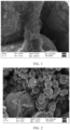
- FIG. 1 shows an SEM image (a) of the positive electrode plate.
- a carbon nanotube bundle is formed from 400 first carbon nanotubes, and the diameter of the first carbon nanotube is 20 nm.
- FIG. 2 shows an SEM image (b) of the carbon nanotube bundles in the 1# positive electrode plate.
- an area of 20 ⁇ m ⁇ 20 ⁇ m there are 6 carbon nanotube bundles.
- the average length of the carbon nanotube bundles is 5 ⁇ m, the average tube diameter is 0.4 ⁇ m, and the length-to-diameter ratio is 12.5.
- FIG. 3 is an SEM image (c) of the second carbon nanotubes in the 1# positive electrode plate.
- the average length of the second carbon nanotubes is 0.4 ⁇ m, and the average diameter of the second carbon nanotubes is 5 nm.
- the second carbon nanotubes are attached onto the surface of the positive active material and the surface of the carbon nanotube bundle.
- Test method Charge a lithium-ion battery at a current of 3 C in a (25 ⁇ 3) °C environment until the voltage reaches 4.4 V, and then charge the battery at a constant voltage until the current reaches to 0.4 C. Record the charging time.
- Embodime nt 2-2 1# 0.30% 2# 0.5% 6 0.22 52.0 64.5 90.8% 45.1 92. 2% 72.8% Embodime nt 2-3 1# 0.30% 3# 0.5% 6 0.38 52.9 65.7 90.3% 45.1 90. 9% 71.3% Embodime nt 2-4 1# 0.30% 4# 0.5% 6 0.13 52.1 63.0 91.6% 44.5 91. 7% 72.0%
- Embodime nt 2-5 1# 0.30% 5# 0.5% 6 0.46 52.9 65.6 90.3% 45.3 91. 2% 71.4% Embodime nt 2-6 1# 0.30% 6# 0.5% 6 0.2 51.8 65.3 90.5% 45.1 91.
- Embodime nt 2-7 1# 0.30% 7# 0.5% 6 0.28 52.3 64.7 91.5% 44.7 91. 8%
- Embodime nt 2-8 1# 0.30% 8# 0.5% 6 0.33 52.4 64.7 91.6% 44.9 92. 1%
- Embodime nt 2-9 1# 0.30% 9# 0.5% 6 0.39 52.6 65.0 91.2% 44.9 92. 2%
- Embodime nt 2-10 1# 0.30% 10# 0.5% 6 0.47 53.7 66.0 90.8% 45.6 91. 9% 71.2%
- Embodime nt 2-11 1# 0.30% 1# 0.2% 6 0.42 54.2 66.1 91.0% 45.7 91.
- the positive active material layer includes the carbon nanotube bundles and the length-to-diameter ratio of the carbon nanotube bundles is 2.5 to 100
- the DCR, rate performance, and low-temperature performance of the battery are improved and the charging time is shortened in contrast to the battery containing no carbon nanotube bundles.
- the battery contains the carbon nanotube bundles and the second carbon nanotubes and the parameters satisfy the specified conditions, the cycle life of the battery is improved.
- R ⁇ m ⁇ 5 the battery achieves superior overall performance.
- Embodiment 1-1 when the battery contains the second carbon nanotubes, the DCR, rate performance, and low-temperature performance of the battery are improved and the charging time is shortened in contrast to the battery containing no second carbon nanotubes.
- the battery achieves superior overall performance such as a low DCR, good rate performance, good low-temperature performance, and long cycle life.
- Embodiment 1-18 to Embodiment 1-23 for the carbon nanotube bundles in an area of 20 ⁇ m ⁇ 20 ⁇ m, when the number of carbon nanotube bundles is 2 to 30, the carbon nanotube bundles wrap the surface of the active material, the ion conductivity is high, the formed conductive network is relatively complete, and the overall performance of the battery is good.
Landscapes
- Chemical & Material Sciences (AREA)
- Engineering & Computer Science (AREA)
- General Chemical & Material Sciences (AREA)
- Chemical Kinetics & Catalysis (AREA)
- Electrochemistry (AREA)
- Manufacturing & Machinery (AREA)
- Nanotechnology (AREA)
- Materials Engineering (AREA)
- Composite Materials (AREA)
- Physics & Mathematics (AREA)
- Condensed Matter Physics & Semiconductors (AREA)
- General Physics & Mathematics (AREA)
- Crystallography & Structural Chemistry (AREA)
- Battery Electrode And Active Subsutance (AREA)
- Carbon And Carbon Compounds (AREA)
Abstract
Description
- This application claims priority to
Chinese Patent Application No. 2022102138839, filed on March 7, 2022 - This application relates to the technical field of batteries, and in particular, to a secondary battery and an electronic device.
- A positive electrode plate of a secondary battery keeps expanding and shrinking during charge-and-discharge cycles of the secondary battery in use, thereby disrupting a part of a conductive network of the battery and leading to growth of a direct current resistance (DCR) of the battery. The DCR growth of the battery leads to deterioration of the rate performance and charging performance and rapid life fading of the battery. Therefore, efforts still need to be made to significantly suppress the DCR growth.
- This application provides a secondary battery, including a positive electrode plate. The positive electrode plate includes carbon nanotube bundles. The carbon nanotube bundle includes a plurality of first carbon nanotubes. The existence of carbon nanotube bundles not only reduce an initial DCR of the battery, but also ensure integrity of a conductive network during cycling, effectively reduce the DCR growth during cycling, improve the cycle life of the battery, and increase the charging speed.
- A secondary battery disclosed herein includes a positive electrode plate. The positive electrode plate includes a current collector and a positive active material layer. The positive active material layer includes a positive active material and a carbon material. The carbon material includes carbon nanotube bundles with a length-to-diameter ratio of 2.5 to 100. The carbon nanotube bundle includes a plurality of first carbon nanotubes.
- Optionally, the carbon nanotube bundle satisfies at least one of the following conditions:
- (i) an average length of the carbon nanotube bundles is 2 µm to 10 µm; and
- (ii) an average tube diameter of the carbon nanotube bundles is 0.01 µm to 2 µm.
- Optionally, the number of the carbon nanotube bundles within an area of 20 µm × 20 µm is m, as measured in a scanning electron microscope test, and a value range of m is 2 ≤ m ≤ 30.
- Optionally, the first carbon nanotubes satisfy at least one of the following conditions:
- (I) a diameter of each first carbon nanotube is in a value range of 5 nm to 40 nm; and
- (II) an average number of the first carbon nanotubes in each carbon nanotube bundle is n, and a value range of n is 50 ≤ n ≤ 10000.
- Optionally, the carbon material further includes second carbon nanotubes, and the second carbon nanotubes exist on a surface of a particle of the positive active material.
- Optionally, the second carbon nanotubes exist on a surface of the carbon nanotube bundle.
- Optionally, the second carbon nanotubes satisfy at least one of the following conditions:
- (a) an average length of the second carbon nanotubes is 0.1 µm to 2 µm; and
- (b) an average diameter of the second carbon nanotubes is 3 nm to 40 nm.
- Optionally, based on a total mass of the positive active material layer, a mass percent of the carbon nanotube bundles is 0.1% to 1%; and/or
a mass percent of the second carbon nanotubes is 0.1% to 1%. - Optionally, based on a total mass of the positive active material layer, a mass percent of the carbon nanotube bundles is less than a mass percent of the second carbon nanotubes.
- Optionally, a fully-charged-state film resistance of the positive electrode is R Ω, and the number of the carbon nanotube bundles within an area of 20 µm × 20 µm is m, as measured in a scanning electron microscope test.
- The fully-charged-state film resistance and the number of the carbon nanotube bundles satisfy Formula I:

- Optionally, 0 < R ≤ 0.5.
- Optionally, based on a total mass of the positive active material layer, a mass percent of the carbon material is 0.1% to 2%.
- According to a second aspect of this application, this application further provides a method for preparing the positive electrode plate described above. The method includes:
- Specifically, the method for preparing the positive electrode plate includes:
- 1) mixing a positive active material, a carbon material, a binder, and a solvent (such as deionized water or N-methyl-pyrrolidone) evenly to make a slurry;
- 2) coating a target region of a current collector aluminum foil with the slurry made in step 1);
- 3) drying the solvent to obtain an elementary electrode plate coated with a positive active material layer; and
- 4) drying, rolling, and slitting the elementary electrode plate obtained in step 3) to obtain a positive electrode plate (also referred to as a positive electrode).
- The carbon material includes carbon nanotube bundles, or includes carbon nanotube bundles and second carbon nanotubes.
- According to a third aspect of this application, this application further provides an electronic device. The electronic device includes any one of the secondary batteries disclosed above.
- The technical solutions provided in this application bring at least the following beneficial effects:
- (1) In this application, carbon nanotube bundles are included in the positive electrode plate. Each carbon nanotube bundle includes a plurality of first carbon nanotubes, thereby not only reducing an initial direct-current resistance (DCR) of the battery, but also ensuring integrity of a conductive network during cycling, effectively reducing the DCR growth during cycling, and increasing the charging speed. Specifically, during cycling of the battery, as the positive active material layer keeps expanding and shrinking, the conductive network in the positive active material layer is disrupted, the contact between particles of the positive active material becomes poor, the electron transport is impaired and the DCR increases. By adding carbon nanotube bundles, this application forms a firmer conductive network, ensures integrity of the conductive network during cycling and reduces DCR growth.
- (2) Compared with a battery containing no carbon nanotube bundles or a battery in which the parameters of the carbon nanotube bundles and the second carbon nanotubes fail to satisfy the specified conditions, the cycle life of the battery containing the carbon nanotube bundles and the second carbon nanotubes has been improved and the direct-current resistance has been reduced.
- (3) In this application, the addition of second carbon nanotubes into the carbon material achieves an effect of further improving the battery life.
- (4) In this application, the product of the value of the fully-charged-state film resistance and the number of carbon nanotube bundles is less than or equal to 5, and the fully-charged-state film resistance value is less than or equal to 0.5 S2, thereby achieving an effect of improving the low-temperature performance of the battery.
- To describe the technical solutions in some embodiments of this application more clearly, the following outlines the drawings to be used in said embodiments. Evidently, the drawings outlined below are merely a part of embodiments of this application. A person of ordinary skill in the art may derive other drawings from the outlined drawings without making any creative efforts.
-
FIG. 1 is a scanning electron microscope (SEM) image of a positive electrode plate according to Embodiment 1-3 of this application; -
FIG. 2 is an SEM image of the carbon nanotube bundles according to Embodiment 1-3 of this application; and -
FIG. 3 is an SEM image of the second carbon nanotubes according to Embodiment 1-3 of this application. - In the prior art, DCR growth brings many adverse effects on a battery, such as deterioration of rate performance, shortened battery life, and long charging time. Therefore, the DCR growth of the battery usually needs to be suppressed by means of reducing the thickness of a positive electrode plate and increasing dosage of a conductive agent. However, these means usually lead to a significant loss of the energy density of the battery and even achieve an insignificant effect of suppressing the DCR growth.
- This application provides a positive electrode plate. The positive electrode plate includes a current collector and a positive active material layer. The positive active material layer includes a positive active material and a carbon material. The carbon material includes carbon nanotube bundles with a length-to-diameter ratio greater than or equal to 2.5 but less than or equal to 100. The carbon nanotube bundle includes a plurality of first carbon nanotubes.
- Specifically, the length-to-diameter ratio of the carbon nanotube bundles falls within a range formed by any two of 5, 7, 10, 12.5, 20, 25, 50, 80, or 100.
- Optionally, the carbon material includes carbon nanotube bundles with a length-to-diameter ratio greater than or equal to 3 but less than or equal to 80.
- Optionally, the carbon material includes carbon nanotube bundles with a length-to-diameter ratio greater than or equal to 3 but less than or equal to 70.
- Optionally, the carbon material includes carbon nanotube bundles with a length-to-diameter ratio greater than or equal to 3 but less than or equal to 50.
- Optionally, the carbon material includes carbon nanotube bundles with a length-to-diameter ratio greater than or equal to 3 but less than or equal to 40.
- The length-to-diameter ratio is a ratio of an average length of the carbon nanotube bundle to an average tube diameter.
- In some embodiments of this application, a plurality of first carbon nanotubes form a carbon nanotube bundle, thereby increasing the length-to-diameter ratio of the carbon nanotube bundle, and effectively improving the electrical conductivity of the positive electrode plate. In addition, the bundles can be dispersed easily, thereby ensuring uniformity of dispersion of a positive slurry. The bundled carbon nanotubes are less prone to disruption than the commonly used individual carbon nanotubes.
- Optionally, the positive active material includes lithium cobalt oxide, lithium nickel cobalt manganese oxide, lithium nickel cobalt manganese aluminum oxide, lithium iron phosphate, and lithium manganese oxide.
- Optionally, an average length of the carbon nanotube bundles is 2 µm to 10 µm.
- Specifically, the average length of the carbon nanotube bundles falls within a range formed by any two of 2 µm, 5 µm, 8 µm, or 10 µm.
- Optionally, an average tube diameter of the carbon nanotube bundles is 0.01 µm to 2 µm.
- Specifically, the average tube diameter of the carbon nanotube bundles falls within a range formed by any two of 0.01 µm, 0.05 µm, 0.1 µm, 0.2 µm, 0.4 µm, 0.5 µm, 0.7 µm, 1 µm, or 2 µm.
- Optionally, the average tube diameter of the carbon nanotube bundles is 0.01 µm to 1.8 µm.
- Optionally, the average tube diameter of the carbon nanotube bundles is 0.01 µm to 1.5 µm.
- Optionally, the average tube diameter of the carbon nanotube bundles is 0.05 µm to 1.2 µm.
- Specifically, the average length is measured by using a scanning electron microscope according to the following method: measuring the length of the carbon nanotube bundles in an area of 20 µm × 20 µm, and averaging out the lengths of all carbon nanotube bundles in the area to obtain an average length.
- The average tube diameter is measured by using a scanning electron microscope according to the following method: measuring the tube diameter of the carbon nanotube bundles in an area of 20 µm × 20 µm, measuring the width of each carbon nanotube bundle for 1 time at 3 different positions on the bundle, and denoting the measured value as the tube diameter of the carbon nanotube bundle, and averaging out the tube diameters of all carbon nanotube bundles in the area to obtain an average tube diameter.
- In this application, the average length, average tube diameter, and length-to-diameter ratio are set to fall within the foregoing ranges, thereby achieving superior overall performance such as a low DCR, good rate performance, good low-temperature performance, and long cycle life.
- Optionally, the number of the carbon nanotube bundles within an area of 20 µm × 20 µm is m, as measured in a scanning electron microscope test, and a value range of m is 2 ≤ m ≤ 30.
- In this application, excessive carbon nanotube bundles fully wrap the surface of the positive active material, thereby impairing ion conductivity. Deficient carbon nanotube bundles lead to an incomplete conductive network. Therefore, the number of the carbon nanotube bundles is set to fall within an appropriate range to ensure both integrity of the conductive network and high efficiency of ion transport.
- Optionally, the diameter of the first carbon nanotube is 5 nm to 40 nm.
- The diameter of the first carbon nanotube falls within a range formed by any two of 5 nm, 15 nm, 20 nm, 30 nm, 40 nm, or 50 nm.
- Optionally, the average number of the first carbon nanotubes in each carbon nanotube bundle is n, and the value range of n is 50 ≤ n ≤ 10000. In this application, an SEM image is selected in which a cross-section of the carbon nanotube bundle is shown. The number of the first carbon nanotubes on the cross-section of a carbon nanotube bundle is determined. The numbers of the first carbon nanotubes in 5 carbon nanotube bundles are counted and averaged out. The average value is rounded off to obtain the average number of the first carbon nanotubes.
- In this application, the diameter of the first carbon nanotube falls within the range of 5 nm to 40 nm. If the diameter of the first carbon nanotube is too small, the first carbon nanotubes can be hardly dispersed. If the diameter of the first carbon nanotube is too large, the first carbon nanotubes are prone to be disrupted during dispersion, and can hardly maintain a high length-to-diameter ratio. In this application, the testing method of the diameter of the first carbon nanotube is the same as the testing method of the average number of the first carbon nanotubes except that the measurement data is the diameter of the first carbon nanotube.
- The number of the first carbon nanotubes in a carbon nanotube bundle falls within the foregoing range, so that the tube diameter, the diameter, and the conductivity of the carbon nanotube bundle fall within an appropriate range, thereby preventing excessive wrapping of the positive active material by the carbon nanotube bundle, reducing the impact on ion transport, and making the carbon nanotube bundles less prone to disruption during cycling.
- Optionally, the carbon material further includes second carbon nanotubes. The second carbon nanotubes are attached onto the surface of the positive active material and the surface of the carbon nanotube bundle.
- The second carbon nanotubes in this application are individual carbon nanotubes.
- In this application, the carbon nanotube bundle provides a main electronic channel. Electrons can be quickly transported inside a bundle and between the bundle and the positive active material. By connecting the bundle and the active material, the second carbon nanotubes enable quick transport of the electrons to different positions in the active material. The coordination between the two materials achieves the effects of reducing the DCR and improving the cycle life of the battery.
- Optionally, the average length of the second carbon nanotubes is 0.1 µm to 2 µm.
- The average length of the second carbon nanotubes falls within a range formed by any two of 0.2 µm, 0.4 µm, 0.8 µm, 1.5 µm, or 2 µm.
- Optionally, the average diameter of the second carbon nanotubes is 3 nm to 40 nm.
- Optionally, the average diameter of the second carbon nanotubes falls within a range formed by any two of 3 nm, 5 nm, 10 nm, 18 nm, or 25 nm.
- In this patent, the average length and average diameter of the second carbon nanotubes are set to fall within appropriate ranges to improve the cycle life of the battery.
- Optionally, a fully-charged-state film resistance of the positive electrode is R Ω, and the number of the carbon nanotube bundles within an area of 20 µm × 20 µm is m. The fully-charged-state film resistance and the number of carbon nanotube bundles satisfy Formula I and/or Formula II:


- Preferably, the fully-charged-state film resistance and the number of the carbon nanotube bundles satisfy Formula 1-1 and Formula II-1:


- The method for preparing the positive electrode includes:
- Specifically, the method for preparing the positive electrode plate includes:
- 1) mixing a positive active material, a carbon material, a binder, and a solvent (such as deionized water or N-methyl-pyrrolidone) evenly to make a slurry;
- 2) coating a target region of a current collector with the slurry made in step 1);
- 3) drying the solvent to obtain an elementary electrode plate coated with a positive active material layer; and
- 4) drying and rolling the elementary electrode plate obtained in step 3) to
- Specifically, the carbon material may be a conductive agent made by mixing the carbon nanotube bundle with at least one of conductive carbon black or the second carbon nanotubes.
- Optionally, the positive active material layer includes a positive active material, the carbon nanotube bundles, the second carbon nanotubes, and a binder.
- Optionally, the positive active material layer includes a positive active material, the carbon nanotube bundles, the second carbon nanotubes, an Super-P conductive agent, and a binder, between which a mass ratio is (96 to 98): (0.1 to 0.8): (0.2 to 1.0): (0.5 to 1.0): (1.0 to 2.0).
- The following describes detailed embodiments:
The parameters of the carbon nanotube bundles in each example are shown in Table a. The carbon nanotube bundles are commercially available, and may be any carbon nanotube bundles as long as the parameter ranges of the carbon nanotube bundles specified in this application are satisfied.Table a Parameters of carbon nanotube bundles Serial number Average tube diameter (µm) Average length (µm) Length-to-diameter ratio Diameter of first carbon nanotube (nm) Average number of first carbon nanotubes Carbon nanotube bundle 1# 0.4 5 12.5 20 400 2# 0.2 5 25 20 150 3# 0.1 5 50 20 110 4# 0.05 5 100 20 50 5# 1 5 5 20 2500 6# 2 5 2.5 20 10000 7# 0.1 2 20 20 110 8# 0.1 8 80 20 110 9# 0.1 10 100 20 110 10# 0.5 5 10 5 10000 11# 0.5 5 10 15 1100 12# 0.5 5 10 30 280 13# 0.5 5 10 40 150 14# 0.5 5 10 20 50 15# 0.7 5 7.1 20 110 D1 1 2 2 20 2500 D2 0.08 8 103 20 280 - The parameters of the second carbon nanotubes in each example are shown in Table b. The second carbon nanotubes are commercially available, and may be any carbon nanotubes as long as the parameter ranges of the second carbon nanotubes specified in this application are satisfied.
Table b Parameters of second carbon nanotubes Serial number Average length (µm) Average tube diameter (nm) Second carbon nanotube 1# 0.4 5 2# 0.8 5 3# 1.5 5 4# 2 5 5# 0.1 5 6# 0.4 3 7# 0.4 10 8# 0.4 18 9# 0.4 25 10# 0.4 40 - S100. Mix LiCoO2, 1# carbon nanotube bundles, and PVDF at a mass ratio of 98.2: 0.5: 1.3 to make a slurry.
- S200. Coat a target region of a current collector (aluminum foil) with the slurry.
- S300. Dry the slurry at 120 °C to obtain an elementary electrode plate coated with an active material layer.
- S400. Dry and roll the elementary electrode plate obtained in step S300 to obtain a positive electrode plate.
- The preparation method of the positive electrode plate is identical to that in Embodiment 1-1 except that the mass percent of the 1# carbon nanotube bundles is 0.3%.
- Preparing the 1# positive electrode plate:
- S100. Mix LiCoO2, 1# carbon nanotube bundles, and 1# second carbon nanotubes, and PVDF at a specified ratio to make a slurry.
- S200. Coat a target region of a current collector (aluminum foil) with the slurry.
- S300. Dry the slurry at 120 °C to obtain an electrode plate coated with an active material layer.
- S400. Dry and roll the electrode plate obtained in step S300 to obtain a positive electrode plate, denoted as 1# positive electrode plate.
- In Embodiment 1-3, the mass percent of the PVDF in the positive active material layer is 1.3%, the mass percent of the carbon nanotube bundles and the second carbon nanotubes is shown in Table 1, and the remaining ingredient is the positive active material.
- The preparation method of the positive electrode plate is similar to that in Embodiment 1-3 except the parameter values shown in Table 1.
- Embodiment 1-4 to Embodiment 1-17 differ from Embodiment 1-1 in that a different carbon nanotube bundle is used.
- A main difference in Embodiment 1-18 to Embodiment 1-23 is that the number m of carbon nanotube bundles in an area of 20 µm × 20 µm is adjusted.
- A main difference in Embodiment 1-24 to Embodiment 1-26 is that the mass percent of the carbon nanotube bundles is adjusted.
- The parameters adjusted in Embodiment 1-27 and Embodiment 1-28 are shown in Table 1.
- The preparation method of the positive electrode plate is similar to that in Embodiment 1-3 except the parameter values shown in Table 2.
- Embodiment 2-1 to Embodiment 2-10 differ from Embodiment 1-1 primarily in that different second carbon nanotubes are used and the mass percent of the second carbon nanotubes is different.
- The preparation method of the positive electrode plate is similar to that in Embodiment 1-2 except that no carbon nanotube bundles are added. For details, see the data in Table 3.
- The preparation method of the positive electrode plate is similar to that in Embodiment 1-3 except that the carbon nanotube bundles are different and no second carbon nanotubes are added. For details, see the data in Table 3.
- The preparation method of the positive electrode plate is similar to that in Embodiment 1-3 except that the type of the carbon nanotube bundles is adjusted. For details, see the data in Table 3.
- The preparation method of the positive electrode plate is similar to that in Embodiment 1-3 except that the type of the carbon nanotube bundles is adjusted. For details, see the data in Table 3.
- An SEM test is carried out for positive electrode plate samples prepared in some embodiments and comparative embodiments respectively.
- The 1# positive electrode plate in Embodiment 1-3 is used as a typical representative, and
FIG. 1 shows an SEM image (a) of the positive electrode plate. As can be seen from the drawing, a carbon nanotube bundle is formed from 400 first carbon nanotubes, and the diameter of the first carbon nanotube is 20 nm. -
FIG. 2 shows an SEM image (b) of the carbon nanotube bundles in the 1# positive electrode plate. In an area of 20 µm × 20 µm, there are 6 carbon nanotube bundles. The average length of the carbon nanotube bundles is 5 µm, the average tube diameter is 0.4 µm, and the length-to-diameter ratio is 12.5. -
FIG. 3 is an SEM image (c) of the second carbon nanotubes in the 1# positive electrode plate. As can be seen from this drawing, the average length of the second carbon nanotubes is 0.4 µm, and the average diameter of the second carbon nanotubes is 5 nm. The second carbon nanotubes are attached onto the surface of the positive active material and the surface of the carbon nanotube bundle. - Stack a positive electrode, a separator, and a negative electrode in sequence so that the separator is located between the positive electrode and the negative electrode to serve a purpose of isolation. Wind the stacked structure to obtain an electrode assembly. Put the electrode assembly into an outer package, and inject the prepared electrolyte. Seal the package and perform steps such as chemical formation, degassing, and edge trimming to obtain a battery.
-
- 1) Charge a lithium-ion battery at a constant current of 0.05 C rate until the voltage reaches 4.4 V, and then charge the battery at a constant voltage until the current reaches a cut-off current of 0.025 C so that the lithium-ion battery reaches a fully charged state.
- 2) Disassemble the lithium-ion battery to obtain a positive electrode plate.
- 3) Place the positive electrode plate obtained in step 2) in an environment with a humidity of 5% to 15% to stand for 30 minutes, and then seal the positive electrode plate and relocate it to a resistance test site.
- 4) Use a BER1200 film resistance tester to test the resistance of the positive electrode plate obtained in step 3). Space out adjacent test points at intervals of 2 mm to 3 mm. Choose 15 different points at least for testing. The average resistance value of all test points is recorded as a fully-charged-state wet film resistance of the positive electrode plate. The test parameters are listed as follows: the area of a press head is 153.94 mm2, the pressure is 3.5 t, and the holding time is 50 s.
- The test results are shown in Table 1, Table 2, and Table 3.
- Charge a lithium-ion battery at a current of 0.5 C in a (25±3) °C environment until the voltage reaches 4.4 V, and then charge the battery at a constant voltage until the current reaches to 0.05 C. Subsequently, discharge the battery at a current of 1 C until the voltage reaches 3.0 V, thereby completing a cycle. Repeat the foregoing steps until the end of 500 cycles, and then determine a ratio of the remaining capacity of the battery to the initial capacity, that is, a capacity retention rate.
- The test results are shown in Table 1, Table 2, and Table 3.
- Charge a lithium-ion battery at a current of 0.5 C in a (25±3) °C environment until the voltage reaches 4.4 V, and then charge the battery at a constant voltage until the current reaches to 0.05 C. Subsequently, discharge the battery at a current of 0.1 C for 2 hours, and then leave the battery to stand for 1 hour. Afterward, discharge the battery at a current of 0.1 C (I1) for 10 seconds, and record a discharge voltage Vi at the last second. Discharge the battery at a current of 1 C (I2) for 1 second, and record the discharge voltage V2 at the last second. Calculate the DCR according to: DCR = (V1 - V2)/(I2 - I1).
- Test method: Charge a lithium-ion battery at a current of 3 C in a (25±3) °C environment until the voltage reaches 4.4 V, and then charge the battery at a constant voltage until the current reaches to 0.4 C. Record the charging time.
- The test results are shown in Table 1, Table 2, and Table 3.
- Charge a battery at a current of 0.5 C in a (25±3) °C environment until the voltage reaches 4.4 V, and then charge the battery at a constant voltage of 4.4 V until the current reaches 0.05 C. Subsequently, fully discharge the battery at a current of 0.2 C and a current of 2 C separately to obtain a 0.2 C discharge capacity value and a 2 C discharge capacity value respectively. Obtain a 2 C discharge rate value by dividing the 2 C discharge capacity value by the 0.2 C discharge capacity value.
- The test results are shown in Table 1, Table 2, and Table 3.
- Charge a battery at a current of 0.5 C in a (25±3) °C environment until the voltage reaches 4.4 V, and then charge the battery at a constant voltage of 4.4 V until the current reaches 0.05 C. Subsequently, discharge the battery at a current of 0.2 C under temperatures of 25 °C and -20 °C separately. Obtain a low-temperature discharge rate value by dividing the -20 °C discharge capacity value by the 25 °C discharge capacity value.
- The test results are shown in Table 1, Table 2, and Table 3.
Table 1 Example Carbon nanotube bundle Second carbon nanotube Number (m) of carbon nanotub e bundles Fully-charged-state film resistanc e (R) DCR (mΩ) Capacit y retentio n rate Chargin g time (min) Rate Low-temperatur e discharge rate Ingredien t Mass percent Ingredien t Mass percent Initia 1 DCR 500th cycle DCR Embodiment 1-1 1# 0.50% / / 6 0.23 55.9 67.8 86.9% 44.8 87.9 % 68.8% Embodiment 1-2 1# 0.30% / / 6 0.30 56.8 68.3 85.5% 47.3 86.5 % 67.3% Embodiment 1-3 1# 0.30% 1# 0.50% 6 0.25 52.0 64.9 91.1% 45.0 92.3 % 73.5% Embodiment 1-4 2# 0.30% 1# 0.50% 6 0.23 51.7 63.2 91.2% 44.7 92.2 % 72.9% Embodiment 1-5 3# 0.30% 1# 0.50% 6 0.19 51.4 62.7 90.9% 44.9 92.5 % 73.0% Embodiment 1-6 4# 0.30% 1# 0.50% 6 0.11 52.7 64.0 89.3% 45.3 90.5 % 70.1% Embodiment 1-7 5# 0.30% 1# 0.50% 6 0.28 51.7 60.1 91.7% 44.2 91.7 % 73.0% Embodiment 1-8 6# 0.30% 1# 0.50% 6 0.50 54.8 67.6 88.4% 45.1 88.3 % 69.4% Embodiment 1-9 7# 0.30% 1# 0.50% 6 0.27 50.1 63.9 91.3% 44.1 92.0 % 73.3% Embodiment 1-10 8# 0.30% 1# 0.50% 6 0.35 52.6 64.2 90.5% 44.9 91.1 % 71.3% Embodiment 1-11 9# 0.30% 1# 0.50% 6 0.30 52.8 63.0 90.9% 44.6 90.8 % 71.0% Embodiment 1-12 10# 0.30% 1# 0.50% 6 0.27 53.3 61.4 90.8% 44.7 90.9 % 71.0% Embodiment 1-13 11# 0.30% 1# 0.50% 6 0.16 51.3 57.6 91.9% 44.3 91.7 % 72.9% Embodiment 1-14 12# 0.30% 1# 0.50% 6 0.19 51.5 58.1 91.8% 44.3 91.5 % 73.0% Embodiment 1-15 13# 0.30% 1# 0.50% 6 0.21 51.9 58.4 92.0% 44.5 91.7 % 72.7% Embodiment 1-16 14# 0.30% 1# 0.50% 6 0.23 52.3 61.7 90.6% 44.9 90.4 % 71.6% Embodiment 1-17 15# 0.30% 1# 0.50% 6 0.27 52.5 61.9 90.5% 44.6 90.1 % 71.9% Embodiment 1-18 2# 0.10% 1# 0.50% 2 0.43 54.5 66.7 89.3% 45.4 89.7 % 70.9% Embodiment 1-19 2# 0.40% 1# 0.50% 10 0.22 51.5 63.0 90.5% 45.0 92.5 % 72.9% Embodiment 1-20 2# 0.50% 1# 0.50% 15 0.17 50.9 62.3 90.8% 44.5 92.8 % 72.9% Embodiment 1-21 2# 0.80% 1# 0.50% 22 0.13 50.3 61.5 90.4% 44.3 92.6 % 72.6% Embodiment 1-22 2# 1.00% 1# 0.50% 30 0.08 49.8 61.4 90.7% 44.2 92.5 % 72.3% Embodiment 1-23 2# 1.10% 1# 0.50% 32 0.08 49.9 62.3 90.1% 44.9 91.7 % 71.9% Embodiment 1-24 10# 0.10% 1# 0.50% 6 0.50 53.8 65.5 89.7% 45.2 90.9 % 72.5% Embodiment 1-25 7# 0.50% 1# 0.50% 6 0.16 51.2 64.0 91.5% 44.9 92.5 % 72.9% Embodiment 1-26 3# 0.80% 1# 0.50% 6 0.10 50.7 63.2 91.6% 44.7 92.3 % 72.8% Embodiment 1-27 1# 0.05% 1# 0.50% 1 0.7 55.9 75.5 88.5% 46.1 89.7 % 69.1% Embodiment 1-28 14# 0.30% 1# 0.50% 2 0.53 52.3 72.0 87.3% 45.7 89.9 % 68.7% Table 2 Example Carbon nanotube bundle Second carbon nanotube Number (m) of carbon nanotube bundles Fully-charged-state film resistance (R) DCR (mΩ) Capacity retention rate Chargi ng time (min) Rat e Low-temperature discharge rate Ingre dient Mass percent Ingred ient Mass percent Initial DCR 500th-cycle DCR Embodime nt 2-1 1# 0.30% 1# 0.8% 6 0.25 52.0 64.9 91.1% 45.0 92. 3% 72.5% Embodime nt 2-2 1# 0.30% 2# 0.5% 6 0.22 52.0 64.5 90.8% 45.1 92. 2% 72.8% Embodime nt 2-3 1# 0.30% 3# 0.5% 6 0.38 52.9 65.7 90.3% 45.1 90. 9% 71.3% Embodime nt 2-4 1# 0.30% 4# 0.5% 6 0.13 52.1 63.0 91.6% 44.5 91. 7% 72.0% Embodime nt 2-5 1# 0.30% 5# 0.5% 6 0.46 52.9 65.6 90.3% 45.3 91. 2% 71.4% Embodime nt 2-6 1# 0.30% 6# 0.5% 6 0.2 51.8 65.3 90.5% 45.1 91. 5% 71.1% Embodime nt 2-7 1# 0.30% 7# 0.5% 6 0.28 52.3 64.7 91.5% 44.7 91. 8% 72.1% Embodime nt 2-8 1# 0.30% 8# 0.5% 6 0.33 52.4 64.7 91.6% 44.9 92. 1% 72.3% Embodime nt 2-9 1# 0.30% 9# 0.5% 6 0.39 52.6 65.0 91.2% 44.9 92. 2% 72.0% Embodime nt 2-10 1# 0.30% 10# 0.5% 6 0.47 53.7 66.0 90.8% 45.6 91. 9% 71.2% Embodime nt 2-11 1# 0.30% 1# 0.2% 6 0.42 54.2 66.1 91.0% 45.7 91. 9% 72.1% Embodime nt 2-12 1# 0.30% 1# 0.3% 6 0.37 53.2 65.9 90.7% 44.9 91. 6% 71.3% Embodime nt 2-12 1# 0.30% 1# 1.0% 6 0.15 51.2 63.9 91.2% 44.9 91. 6% 71.3% Table 3 Example Carbon nanotube bundle Second carbon nanotube Number (m) of carbon nanotube bundles Fully-charged-state film resistance (R) DCR (mΩ) Capacity retention rate Chargin g time (min) Rate Low-temperature discharge rate Ingre dient Mass percent Ingre dient Mass percent Initial DCR 500th-cycle DCR Comparative Embodiment 1 / / 1# 0.50% 0 0.97 63.4 79.3 77.0% 56.7 80.5 % 58.8% Comparative Embodiment 2 D1 0.30% / / 6 0.85 62.4 78.6 79.0% 53.3 81.3 % 59.2% Comparative Embodiment 3 D1 0.30% 1# 0.50% 6 0.57 61.7 77.1 80.0% 51.7 82.0 % 60.2% Comparative Embodiment 4 D2 0.30% 1# 0.50% 4 0.65 61.1 77.9 79.4% 52.1 81.7 % 59.7% - As can be seen from comparison between Table 1 and Comparative Embodiments 1 to 4, when the positive active material layer includes the carbon nanotube bundles and the length-to-diameter ratio of the carbon nanotube bundles is 2.5 to 100, the DCR, rate performance, and low-temperature performance of the battery are improved and the charging time is shortened in contrast to the battery containing no carbon nanotube bundles. In addition, when the battery contains the carbon nanotube bundles and the second carbon nanotubes and the parameters satisfy the specified conditions, the cycle life of the battery is improved. When R × m ≤ 5, the battery achieves superior overall performance.
- As can be seen from comparison between Embodiment 1-1, Embodiment 1-2, and Embodiment 1-3, when the battery contains the second carbon nanotubes, the DCR, rate performance, and low-temperature performance of the battery are improved and the charging time is shortened in contrast to the battery containing no second carbon nanotubes.
- As can be seen from Embodiment 1-3 to Embodiment 1-17, when the average length, average tube diameter, and length-to-diameter ratio of the carbon nanotube bundles are set to fall within appropriate ranges, the battery achieves superior overall performance such as a low DCR, good rate performance, good low-temperature performance, and long cycle life.
- As can be seen from Embodiment 1-18 to Embodiment 1-23, for the carbon nanotube bundles in an area of 20 µm × 20 µm, when the number of carbon nanotube bundles is 2 to 30, the carbon nanotube bundles wrap the surface of the active material, the ion conductivity is high, the formed conductive network is relatively complete, and the overall performance of the battery is good.
- As can be seen from Table 2, when the average length and average diameter of the second carbon nanotubes are set to fall within appropriate ranges, the overall performance of the battery is improved.
- What is described above is merely preferred embodiments of this application, but not intended to limit the scope of this application. All types of variations and improvements made by a person of ordinary skill in the art without departing from the conception of this application still fall within the protection scope defined by the claims of this application.
Claims (12)
- A secondary battery, comprising a positive electrode plate, characterized in that, the positive electrode plate comprises a current collector and a positive active material layer;the positive active material layer comprises a positive active material and a carbon material;the carbon material comprises carbon nanotube bundles with a length-to-diameter ratio of 2.5 to 100;a carbon nanotube bundle comprises a plurality of first carbon nanotubes.
- The secondary battery according to claim 1, characterized in that, the carbon nanotube bundle satisfies at least one of the following conditions:(i) an average length of the carbon nanotube bundles is 2 µm to 10 µm; and(ii) an average bundle diameter of the carbon nanotube bundles is 0.01 µm to 2 µm.
- The secondary battery according to claim 1, characterized in that, the number of the carbon nanotube bundles within an area of 20 µm × 20 µm of an SEM image is m, and 2 ≤ m ≤ 30.
- The secondary battery according to claim 1, characterized in that, the first carbon nanotubes satisfy at least one of the following conditions:(I) a diameter of each first carbon nanotube is 5 nm to 40 nm; and(II) an average number of the first carbon nanotubes in each carbon nanotube bundle is n, and 50 ≤ n ≤ 10000.
- The secondary battery according to claim 1, characterized in that, the carbon material further comprises second carbon nanotubes, and the second carbon nanotubes exist on a surface of a particle of the positive active material.
- The secondary battery according to claim 5, characterized in that, the second carbon nanotubes satisfy at least one of the following conditions:(a) an average length of the second carbon nanotubes is 0.1 µm to 2 µm; and(b) an average diameter of the second carbon nanotubes is 3 nm to 40 nm.
- The secondary battery according to claim 5, characterized in that, based on a total mass of the positive active material layer, a mass percent of the carbon nanotube bundles is 0.1% to 1%; and/or
a mass percent of the second carbon nanotubes is 0.1% to 1%. - The secondary battery according to claim 5, characterized in that, based on a total mass of the positive active material layer, a mass percent of the carbon nanotube bundles is less than a mass percent of the second carbon nanotubes.
- The secondary battery according to claim 1, characterized in that, a fully-charged-state film resistance of the positive electrode plate is R Ω, and a number of the carbon nanotube bundles within an area of 20 µm × 20 µm of an SEM image is m;
the fully-charged-state film resistance and the number of the carbon nanotube bundles satisfy Formula I:
- The secondary battery according to claim 9, characterized in that, 0 < R ≤ 0.5.
- The secondary battery according to claim 1, characterized in that, based on a total mass of the positive active material layer, a mass percent of the carbon material is 0.1% to 1%.
- An electronic device, characterized in that, the electronic device comprises the secondary battery according to any one of claims 1 to 11.
Applications Claiming Priority (2)
| Application Number | Priority Date | Filing Date | Title |
|---|---|---|---|
| CN202210213883.9A CN114300686B (en) | 2022-03-07 | 2022-03-07 | Secondary battery and electronic device |
| PCT/CN2023/074533 WO2023169113A1 (en) | 2022-03-07 | 2023-02-06 | Secondary battery and electronic device |
Publications (2)
| Publication Number | Publication Date |
|---|---|
| EP4270549A1 true EP4270549A1 (en) | 2023-11-01 |
| EP4270549A4 EP4270549A4 (en) | 2025-03-19 |
Family
ID=87849940
Family Applications (1)
| Application Number | Title | Priority Date | Filing Date |
|---|---|---|---|
| EP23712139.7A Pending EP4270549A4 (en) | 2022-03-07 | 2023-02-06 | Secondary battery and electronic device |
Country Status (5)
| Country | Link |
|---|---|
| US (1) | US20230282835A1 (en) |
| EP (1) | EP4270549A4 (en) |
| JP (1) | JP7504291B2 (en) |
| KR (1) | KR20240147694A (en) |
| CA (1) | CA3194450A1 (en) |
Families Citing this family (2)
| Publication number | Priority date | Publication date | Assignee | Title |
|---|---|---|---|---|
| KR20250101723A (en) * | 2023-12-27 | 2025-07-04 | 주식회사 엘지에너지솔루션 | Positive electrode and secondary battery comprising the same |
| CN121172140B (en) * | 2025-11-20 | 2026-03-27 | 中航锂电(洛阳)有限公司 | Negative electrode, positive electrode and battery |
Family Cites Families (8)
| Publication number | Priority date | Publication date | Assignee | Title |
|---|---|---|---|---|
| JP2009190948A (en) * | 2008-02-15 | 2009-08-27 | Panasonic Corp | Carbon nanotube structure, electrode and electric double layer capacitor using the same |
| JP2013075809A (en) * | 2011-09-30 | 2013-04-25 | Nippon Chemicon Corp | Composite of metal oxide and carbon nanotube, production method of the same, and electrode and electrochemical element using the same |
| CN108028355B (en) * | 2015-11-30 | 2021-03-26 | 株式会社Lg化学 | Positive electrode for secondary battery and secondary battery comprising same |
| KR102101006B1 (en) * | 2015-12-10 | 2020-04-14 | 주식회사 엘지화학 | Positive electrode for secondary battery and secondary battery comprising the same |
| KR102320010B1 (en) * | 2016-03-24 | 2021-11-02 | 주식회사 엘지에너지솔루션 | Conductive material dispersed solution and secondary battery prepared by using the same |
| KR102763148B1 (en) * | 2018-11-08 | 2025-02-07 | 주식회사 엘지에너지솔루션 | Positive electrode active material for lithium secondary battery, method for preparing the same and lithium secondary battery including the positive electrode active material |
| CN113785413B (en) * | 2019-10-04 | 2024-10-01 | 株式会社Lg新能源 | Positive electrode and secondary battery including the same |
| KR20220000508A (en) * | 2020-06-26 | 2022-01-04 | 현대자동차주식회사 | Cathode for lithium air battery having low cell resistance and high mechanical property and preparing method thereof |
-
2023
- 2023-02-06 JP JP2023519293A patent/JP7504291B2/en active Active
- 2023-02-06 CA CA3194450A patent/CA3194450A1/en active Pending
- 2023-02-06 EP EP23712139.7A patent/EP4270549A4/en active Pending
- 2023-02-06 KR KR1020247031356A patent/KR20240147694A/en active Pending
- 2023-03-30 US US18/193,117 patent/US20230282835A1/en active Pending
Also Published As
| Publication number | Publication date |
|---|---|
| EP4270549A4 (en) | 2025-03-19 |
| US20230282835A1 (en) | 2023-09-07 |
| CA3194450A1 (en) | 2023-09-07 |
| JP2024513623A (en) | 2024-03-27 |
| JP7504291B2 (en) | 2024-06-21 |
| KR20240147694A (en) | 2024-10-08 |
Similar Documents
| Publication | Publication Date | Title |
|---|---|---|
| EP3793008B1 (en) | Positive electrode material, preparation method therefor, and use thereof | |
| WO2023169113A1 (en) | Secondary battery and electronic device | |
| US9954247B2 (en) | Cathode mixture, non-aqueous electrolyte secondary battery, and its manufacturing method | |
| US8101295B2 (en) | Lithium secondary battery | |
| CN114335428B (en) | Positive plate, preparation method and battery | |
| BRPI0606912B1 (en) | active cathode material for a secondary lithium battery | |
| JP3491529B2 (en) | Non-aqueous electrolyte secondary battery | |
| CN111584833A (en) | Lithium secondary battery | |
| CN110828886A (en) | Three-electrode lithium ion battery and preparation method thereof | |
| US20240363843A1 (en) | Negative electrode plate and battery | |
| US20230282835A1 (en) | Secondary battery and electronic device | |
| US20030134186A1 (en) | Non-aqueous electrolyte secondary battery | |
| CN101752545A (en) | Electrode of lithium battery, preparation method of electrode and lithium battery adopting electrode | |
| CN111785922A (en) | Lithium-ion battery electrode, preparation method and application thereof, and lithium-ion battery | |
| CN113782915A (en) | Diaphragm and preparation method and application thereof | |
| EP4723192A1 (en) | Lithium-ion battery and electric device | |
| CN115312684B (en) | Positive pole piece and battery | |
| CN118044000A (en) | Negative electrode sheet, secondary battery and electricity utilization device | |
| EP4607604A1 (en) | Electrochemical apparatus and electronic device | |
| CN120237272A (en) | A cylindrical battery | |
| KR20220059927A (en) | Slurry composition for positive electrode of lithium secondary battery | |
| CN118899551A (en) | Battery | |
| KR20230051978A (en) | Negative electrode for secondary battery and electrode assembly containing the same | |
| EP4645438A1 (en) | Lithium-ion battery negative electrode and lithium-ion battery | |
| CN100511783C (en) | Nonaqueous electrolyte secondary battery |
Legal Events
| Date | Code | Title | Description |
|---|---|---|---|
| STAA | Information on the status of an ep patent application or granted ep patent |
Free format text: STATUS: UNKNOWN |
|
| STAA | Information on the status of an ep patent application or granted ep patent |
Free format text: STATUS: THE INTERNATIONAL PUBLICATION HAS BEEN MADE |
|
| PUAI | Public reference made under article 153(3) epc to a published international application that has entered the european phase |
Free format text: ORIGINAL CODE: 0009012 |
|
| STAA | Information on the status of an ep patent application or granted ep patent |
Free format text: STATUS: REQUEST FOR EXAMINATION WAS MADE |
|
| 17P | Request for examination filed |
Effective date: 20230330 |
|
| AK | Designated contracting states |
Kind code of ref document: A1 Designated state(s): AL AT BE BG CH CY CZ DE DK EE ES FI FR GB GR HR HU IE IS IT LI LT LU LV MC ME MK MT NL NO PL PT RO RS SE SI SK SM TR |
|
| REG | Reference to a national code |
Ref country code: DE Ref legal event code: R079 Free format text: PREVIOUS MAIN CLASS: H01M0004620000 Ipc: H01M0004131000 |
|
| A4 | Supplementary search report drawn up and despatched |
Effective date: 20250214 |
|
| RIC1 | Information provided on ipc code assigned before grant |
Ipc: H01M 4/02 20060101ALN20250210BHEP Ipc: H01M 4/525 20100101ALN20250210BHEP Ipc: B82Y 40/00 20110101ALI20250210BHEP Ipc: B82Y 30/00 20110101ALI20250210BHEP Ipc: H01M 10/052 20100101ALI20250210BHEP Ipc: H01M 4/36 20060101ALI20250210BHEP Ipc: H01M 4/62 20060101ALI20250210BHEP Ipc: H01M 4/131 20100101AFI20250210BHEP |
|
| DAV | Request for validation of the european patent (deleted) | ||
| DAX | Request for extension of the european patent (deleted) |