EP4270506A1 - Magnetic sensor and biomagnetism measuring apparatus - Google Patents
Magnetic sensor and biomagnetism measuring apparatus Download PDFInfo
- Publication number
- EP4270506A1 EP4270506A1 EP21910811.5A EP21910811A EP4270506A1 EP 4270506 A1 EP4270506 A1 EP 4270506A1 EP 21910811 A EP21910811 A EP 21910811A EP 4270506 A1 EP4270506 A1 EP 4270506A1
- Authority
- EP
- European Patent Office
- Prior art keywords
- signal
- pickup coil
- magnetic sensor
- measurement unit
- information processing
- Prior art date
- Legal status (The legal status is an assumption and is not a legal conclusion. Google has not performed a legal analysis and makes no representation as to the accuracy of the status listed.)
- Withdrawn
Links
Images




Classifications
-
- G—PHYSICS
- G01—MEASURING; TESTING
- G01R—MEASURING ELECTRIC VARIABLES; MEASURING MAGNETIC VARIABLES
- G01R33/00—Arrangements or instruments for measuring magnetic variables
- G01R33/0023—Electronic aspects, e.g. circuits for stimulation, evaluation, control; Treating the measured signals; calibration
- G01R33/0029—Treating the measured signals, e.g. removing offset or noise
-
- G—PHYSICS
- G01—MEASURING; TESTING
- G01R—MEASURING ELECTRIC VARIABLES; MEASURING MAGNETIC VARIABLES
- G01R33/00—Arrangements or instruments for measuring magnetic variables
- G01R33/0017—Means for compensating offset magnetic fields or the magnetic flux to be measured; Means for generating calibration magnetic fields
-
- G—PHYSICS
- G01—MEASURING; TESTING
- G01R—MEASURING ELECTRIC VARIABLES; MEASURING MAGNETIC VARIABLES
- G01R33/00—Arrangements or instruments for measuring magnetic variables
- G01R33/02—Measuring direction or magnitude of magnetic fields or magnetic flux
- G01R33/04—Measuring direction or magnitude of magnetic fields or magnetic flux using the flux-gate principle
-
- G—PHYSICS
- G01—MEASURING; TESTING
- G01R—MEASURING ELECTRIC VARIABLES; MEASURING MAGNETIC VARIABLES
- G01R33/00—Arrangements or instruments for measuring magnetic variables
- G01R33/02—Measuring direction or magnitude of magnetic fields or magnetic flux
- G01R33/06—Measuring direction or magnitude of magnetic fields or magnetic flux using galvano-magnetic devices
-
- A—HUMAN NECESSITIES
- A61—MEDICAL OR VETERINARY SCIENCE; HYGIENE
- A61B—DIAGNOSIS; SURGERY; IDENTIFICATION
- A61B5/00—Measuring for diagnostic purposes; Identification of persons
- A61B5/24—Detecting, measuring or recording bioelectric or biomagnetic signals of the body or parts thereof
- A61B5/242—Detecting biomagnetic fields, e.g. magnetic fields produced by bioelectric currents
-
- A—HUMAN NECESSITIES
- A61—MEDICAL OR VETERINARY SCIENCE; HYGIENE
- A61B—DIAGNOSIS; SURGERY; IDENTIFICATION
- A61B5/00—Measuring for diagnostic purposes; Identification of persons
- A61B5/24—Detecting, measuring or recording bioelectric or biomagnetic signals of the body or parts thereof
- A61B5/242—Detecting biomagnetic fields, e.g. magnetic fields produced by bioelectric currents
- A61B5/243—Detecting biomagnetic fields, e.g. magnetic fields produced by bioelectric currents specially adapted for magnetocardiographic [MCG] signals
-
- A—HUMAN NECESSITIES
- A61—MEDICAL OR VETERINARY SCIENCE; HYGIENE
- A61B—DIAGNOSIS; SURGERY; IDENTIFICATION
- A61B5/00—Measuring for diagnostic purposes; Identification of persons
- A61B5/24—Detecting, measuring or recording bioelectric or biomagnetic signals of the body or parts thereof
- A61B5/242—Detecting biomagnetic fields, e.g. magnetic fields produced by bioelectric currents
- A61B5/245—Detecting biomagnetic fields, e.g. magnetic fields produced by bioelectric currents specially adapted for magnetoencephalographic [MEG] signals
-
- G—PHYSICS
- G01—MEASURING; TESTING
- G01R—MEASURING ELECTRIC VARIABLES; MEASURING MAGNETIC VARIABLES
- G01R33/00—Arrangements or instruments for measuring magnetic variables
- G01R33/0023—Electronic aspects, e.g. circuits for stimulation, evaluation, control; Treating the measured signals; calibration
- G01R33/0041—Electronic aspects, e.g. circuits for stimulation, evaluation, control; Treating the measured signals; calibration using feed-back or modulation techniques
-
- G—PHYSICS
- G01—MEASURING; TESTING
- G01R—MEASURING ELECTRIC VARIABLES; MEASURING MAGNETIC VARIABLES
- G01R33/00—Arrangements or instruments for measuring magnetic variables
- G01R33/0094—Sensor arrays
Definitions
- the present invention relates to a magnetic sensor and a biomagnetic measurement device.
- a magnetic sensor which detects an induced voltage corresponding to an external magnetic field, which is induced in a pickup coil by energizing an amorphous wire around which the pickup coil is wound.
- Patent Document 1 discloses that a single pickup coil detects an induced voltage and generates a bias magnetic field by generating the bias magnetic field with the pickup coil.
- Patent Document 1 Japanese Patent No. 5924503
- the pickup coil has a parasitic series resistance
- the pickup coil when the pickup coil is energized to generate a bias magnetic field, a voltage due to the influence of the parasitic series resistance is generated in the pickup coil in addition to the induced voltage corresponding to the external magnetic field. Therefore, when the voltage generated in the pickup coil is detected, a mixed voltage of the induced voltage corresponding to the external magnetic field and the voltage due to the influence of the parasitic series resistance is detected, and the induced voltage corresponding to the external magnetic field cannot be accurately detected, in some cases.
- the present invention has been made in view of such circumstances, and an object of the present invention is to provide a magnetic sensor and a biomagnetic measurement device capable of accurately detecting an induced voltage corresponding to an external magnetic field when detecting an induced voltage and generating a bias magnetic field with one pickup coil.
- connection means that power or electrical signals can be transferred directly or indirectly. Electrical connection may be connection via components such as cables, resistors, capacitors, diodes, circuit breakers, and the like.
- FIG. 1 is a diagram showing an example of a basic configuration of a magnetic sensor 1 according to a first embodiment.
- the magnetic sensor 1 includes a sensor head 100, a drive unit 200, a pickup coil 300, and an information processing unit 400.
- the sensor head 100 includes magnetic material.
- Examples of the sensor head 100 include a magneto-impedance element, a fluxgate sensor, a magnetic core, and the like.
- the magneto-impedance element is an element whose impedance changes with an external magnetic field, and is, for example, an amorphous wire.
- the drive unit 200 energizes the sensor head 100.
- the drive unit 200 energizes the sensor head 100 by outputting a pulse current or a high frequency current.
- a state in which the drive unit 200 energizes the sensor head 100 is referred to as an "energized state", and a state in which the drive unit 200 does not energize the sensor head 100 is referred to as a "non-energized state".
- the pickup coil 300 is disposed close to the sensor head 100. Specifically, the pickup coil 300 is disposed close to the sensor head 100 so that an induced voltage proportional to the external magnetic field is generated in the pickup coil 300 in an energized state. For example, the pickup coil 300 is wound around the sensor head 100. Note that the pickup coil 300 has a parasitic series resistance Rp.
- the information processing unit 400 is connected to the pickup coil 300.
- the information processing unit 400 energizes the pickup coil 300 to generate a bias magnetic field.
- the method of energizing the pickup coil 300 to generate the bias magnetic field is not particularly limited.
- the information processing unit 400 detects a signal corresponding to the voltage generated in the pickup coil 300.
- the signal corresponding to the voltage generated in the pickup coil 300 may be a signal of the voltage itself, may be a signal generated based on the voltage, or may be a signal obtained by subjecting the voltage to predetermined signal processing such as amplification, filtering, and AD conversion.
- the magnetic sensor 1 uses a single pickup coil 300 to detect the voltage generated in the pickup coil 300 and generate the bias magnetic field.
- the information processing unit 400 detects a first signal, which is a signal corresponding to the voltage (hereinafter referred to as a "first voltage”) generated in the pickup coil 300 in the energized state. Also, the information processing unit 400 detects a second signal, which is a signal corresponding to the voltage (hereinafter referred to as a "second voltage") generated in the pickup coil 300 in the non-energized state. The information processing unit 400 then generates a difference signal indicating a difference between the first signal and the second signal. The information processing unit 400 generates an output signal Vout by amplifying the difference signal.
- the order of detection of the first signal and detection of the second signal by the information processing unit 400 is not particularly limited.
- the information processing unit 400 may detect the second signal after detecting the first signal, or may detect the first signal after detecting the second signal.
- the information processing unit 400 of the present embodiment feeds back a current corresponding to the output signal Vout to the pickup coil 300 to energize the pickup coil 300 and generate a bias magnetic field.
- FIG. 2 is a flowchart of the operation of the magnetic sensor 1.
- the magnetic sensor 1 controls the sensor head 100 to be in an energized state by energizing the sensor head 100 (step S101).
- the information processing unit 400 detects a first signal corresponding to a first voltage generated in the pickup coil 300 in the energized state (step S102).
- the pickup coil 300 when the sensor head 100 is energized, a high frequency induced voltage (hereinafter referred to as a "high frequency voltage") corresponding to the external magnetic field is generated in the pickup coil 300.
- the pickup coil 300 is always energized to generate a bias magnetic field, and due to the influence of the parasitic series resistance Rp of the pickup coil 300, a voltage having a frequency lower than that of the high frequency voltage (hereinafter referred to as a "low frequency voltage”) is also generated in the pickup coil 300 at the same time.
- the low frequency voltage is a dynamic offset voltage due to the parasitic series resistance Rp. Therefore, the first voltage generated in the pickup coil 300 in the energized state is a voltage in which at least the high frequency voltage and the low frequency voltage are mixed.
- the magnetic sensor 1 When the magnetic sensor 1 detects the first signal, the magnetic sensor 1 controls the sensor head 100 to be in a non-energized state by stopping the energization to the sensor head 100 (step S103).
- the information processing unit 400 detects a second signal corresponding to a second voltage generated in the pickup coil 300 in the non-energized state (step S104).
- the processes are performed in the order of steps S101, S102, S103, S104, and S105, but the present invention is not limited thereto, and the processes may be performed in the order of steps S103, S104, S101, S102, and S105.
- the second voltage generated in the pickup coil 300 in the non-energized state does not include at least the high frequency voltage, but includes the low frequency voltage due to the parasitic series resistance Rp.
- the information processing unit 400 obtains the difference between the first signal and the second signal to generate a difference signal, thereby extracting only the high frequency voltage signal (difference signal) corresponding to the external magnetic field (step S105).
- the difference signal is a minute signal
- the information processing unit 400 amplifies the difference signal and outputs the output signal Vout, which is an amplified signal, to the outside (step S106). Further, the information processing unit 400 negatively feeds back a signal corresponding to the output signal Vout to the pickup coil 300 (step S107).
- the magnetic sensor 1 samples the signal corresponding to the voltage generated in the pickup coil 300 in each of the energized state and the non-energized state, and obtains a difference between the two sampled signals. Thereby, it is possible to accurately detect an induced voltage (high frequency voltage) corresponding to an external magnetic field when detecting an induced voltage and generating a bias magnetic field with one pickup coil.
- the magnetic sensor 1 can accurately detect the induced voltage corresponding to the external magnetic field, it is possible to negatively feed back the current corresponding to the induced voltage corresponding to the external magnetic field instead of the first voltage and it is possible to suppress the deterioration of the negative feedback effect due to the influence of the parasitic series resistance.
- the first voltage is a voltage in which a high frequency voltage and a low frequency voltage are mixed
- a method of extracting only the high frequency voltage from the first voltage using a high-pass filter is also conceivable.
- the resistive element forming the high-pass filter may become a noise source, degrading the sensitivity of the magnetic sensor 1.
- the value of the capacitive element forming the high-pass filter is large, which is unsuitable for integration of CMOS and the like.
- only the high frequency voltage can be extracted from the first voltage without using a high-pass filter, which is suitable for integration of CMOS and the like.
- the magnetic sensor 1 when the magnetic sensor 1 according to the first embodiment includes an amplifier circuit such as an operational amplifier that amplifies the difference signal, low frequency noise components such as 1/f noise of the amplifier circuit and offset voltage caused by manufacturing variations may be detected as a third signal, and the difference between the third signal and the first signal may be obtained.
- the information processing unit 400 subtracts the second signal and the third signal from the first signal to generate a fourth signal with reduced low frequency noise components, thereby more accurately detecting an induced voltage (high frequency voltage) corresponding to the external magnetic field). In this case, the information processing unit 400 generates the output signal Vout by amplifying the fourth signal with the amplifier circuit.
- the timing at which the information processing unit 400 detects the third signal is not particularly limited, but for example, the third signal is detected in the non-energized state. Further, the information processing unit 400 may obtain a difference signal indicating the difference between the first signal and the second signal and obtain the difference between the difference signal and the third signal to generate the fourth signal, or simultaneously subtract the second signal and the third signal from the first signal. Further, the information processing unit 400 may obtain the difference between the first signal and the third signal, and obtain the difference between the difference signal and the second signal to generate the fourth signal.
- a specific first configuration example of the information processing unit 400 of the first embodiment will be described.
- the configuration of the information processing unit 400 of the first embodiment is not limited to the specific configuration described in the second embodiment.
- portions having functions similar to those described in the first embodiment will be given the same names and reference numerals, and detailed descriptions of the functions will be omitted.
- the magnetic sensor of the second embodiment is called a "magnetic sensor 1A”
- the information processing unit 400 of the second embodiment is called an "information processing unit 400A”.
- FIG. 3 is a diagram showing a configuration example of a magnetic sensor 1A according to the second embodiment.
- the magnetic sensor 1A includes a sensor head 100, a drive unit 200, a pickup coil 300, and an information processing unit 400A.
- the information processing unit 400A includes a first measurement unit 410 and a second measurement unit 420.
- the first measurement unit 410 detects a first signal in the energized state, detects a second signal in the non-energized state, and generates a difference signal indicating a difference between the first signal and the second signal.
- the second measurement unit 420 is connected to the first measurement unit 410.
- the second measurement unit 420 has an amplifier circuit and feeds back a current corresponding to an output signal Vout of the amplifier circuit to the pickup coil 300.
- the second measurement unit 420 detects a third signal in the non-energized state, and generates a fourth signal indicating a difference between the difference signal output from the first measurement unit 410 and the third signal.
- FIG. 4 is a schematic configuration diagram of the first measurement unit 410 and the second measurement unit 420.
- the first measurement unit 410 includes a switch 411, a capacitor 412, and a switch 413.
- the switch 411 has a first end connected to a first end of the pickup coil 300 and a second end connected to a first end of the capacitor 412. A second end of the capacitor 412 is connected to the second measurement unit 420.
- the switch 413 has a first end connected to the second end of the capacitor 412 and a second end connected to the ground.
- the second measurement unit 420 includes an operational amplifier 421, a capacitor 422, a switch 423, a switch 424, a capacitor 425, and a resistor 426.
- the operational amplifier 421 is an example of an amplifier circuit.
- a noninverting input terminal of the operational amplifier 421 is modeled by inputting the low frequency noise component (offset, 1/f noise) of the operational amplifier 421.
- An inverting input terminal of the operational amplifier 421 is connected to the capacitor 422 and the switch 424.
- An output terminal of the operational amplifier 421 is connected to the capacitor 425 and the resistor 426.
- the capacitor 422 has a first end connected to the second end of the capacitor 412 and a second end connected to the inverting input terminal of the operational amplifier 421.
- the switch 423 has a first end connected to the first end of the capacitor 422 and a second end connected to a first end of the capacitor 425.
- the switch 424 has a first end connected to the second end of the capacitor 422 and the second end connected to the first end of the capacitor 425.
- a second end of the capacitor 425 is connected to the output terminal of the operational amplifier 421 and a first end of the resistor 426.
- a second end of the resistor 426 is connected to a first end of the pickup coil 300.
- the operation of the magnetic sensor 1A is roughly divided into three steps (first step, second step, and third step).
- the magnetic sensor 1A repeats operations in the order of the first step, the second step, and the third step.
- the first step is performed in the energized state.
- the second step and the third step are performed in the non-energized state.
- each switch in the first measurement unit 410 and the second measurement unit 420 may be controlled by a processor (not shown) in the magnetic sensor 1A, or may be controlled by the drive unit 200.
- the first measurement unit 410 controls the switch 411 and the switch 413 to be on. Further, in the energized state, the second measurement unit 420 controls the switch 423 to be on, and controls the switch 424 to be off. Accordingly, the first voltage is detected by the capacitor 412 in the energized state.
- the drive unit 200 generates a rectangular pulse current to energize the amorphous wire.
- the first voltage is detected by the capacitor 412 by turning off the switch 411 at an appropriate timing for the peak voltage of the induced voltage (which changes according to the external magnetic field strength to be detected) generated when the rectangular pulse current rises.
- the switch 411 is controlled to be off by the first measurement unit 410, and then the sensor head 100 enters a non-energized state.
- the first measurement unit 410 controls the switch 413 to remain on.
- the second measurement unit 420 controls the switch 423 to be off, and controls the switch 424 to be on. Accordingly, in the second step, due to the effect of the virtual ground of the operational amplifier 421, a low frequency noise component of the operational amplifier is generated at the inverting input terminal, and is sampled by turning off the switch 413.
- the first measurement unit 410 controls the switch 413 to be off, and then controls the switch 411 to be on. Further, the second measurement unit 420 controls the switch 423 to be on, and controls the switch 424 to be off. Accordingly, in the third step, the charge corresponding to the second voltage and the charge corresponding to the low frequency noise component accumulated in the capacitor 422 are subtracted from the charge corresponding to the first voltage accumulated in the capacitor 412, and the remaining charge (fourth signal) is transferred to the capacitor 425 to obtain the corresponding output voltage Vout.
- the magnetic sensor 1A according to the second embodiment has effects similar to those of the first embodiment, and can reduce not only the dynamic offset (low frequency voltage) caused by the parasitic series resistance Rp of the pickup coil 300, but also the low frequency noise component of the operational amplifier 421 in the circuit in the second measurement unit 420.
- a specific second configuration example of the information processing unit 400 of the first embodiment will be described.
- the configuration of the information processing unit 400 of the first embodiment is not limited to the specific configuration described in the third embodiment.
- portions having functions similar to those described in the first embodiment and the second embodiment will be given the same names and reference numerals, and detailed descriptions of the functions will be omitted.
- the magnetic sensor of the third embodiment is called a "magnetic sensor 1B”
- the information processing unit 400 of the third embodiment is called an "information processing unit 400B”.
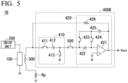
- FIG. 5 is a diagram showing a configuration example of a magnetic sensor 1B according to the third embodiment.
- the magnetic sensor 1B includes a sensor head 100, a drive unit 200, a pickup coil 300, and an information processing unit 400B.
- the information processing unit 400B includes a first measurement unit 410, a second measurement unit 420, and a switch 500.
- the switch 500 can cut off electrical connection between the first measurement unit 410 and the second measurement unit 420.
- the switch 500 has a first end connected to the second end of the capacitor 412 and the second end connected to the first end of the capacitor 422.
- the switch 500 cuts off the electrical connection between the first measurement unit 410 and the second measurement unit 420 when the first measurement unit 410 detects the first signal. This makes it possible to reduce the influence of noise from the second measurement unit 420 when the first measurement unit 410 detects the first signal.
- the switch 500 may be controlled by a processor (not shown) in the magnetic sensor 1B, or may be controlled by the drive unit 200.
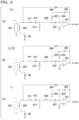
- FIG. 6 is a diagram showing the flow of operation of the magnetic sensor 1B.
- the operation of the magnetic sensor 1B according to the third embodiment is roughly divided into three steps (first step, second step, and third step) as in the second embodiment.
- the magnetic sensor 1B repeats operations in the order of the first step, the second step, and the third step.
- the first step is performed in the energized state.
- the second step and the third step are performed in the non-energized state.
- the sensor head 100 is in an energized state.
- the first measurement unit 410 controls the switch 411 and the switch 413 to be on in advance.
- the second measurement unit 420 controls the switch 423 to be on, and controls the switch 424 to be off.
- the switch 500 is in an off state.
- the first voltage is detected by the capacitor 412 without being affected by noise generated by the second measurement unit 420.
- the drive unit 200 generates a rectangular pulse current to energize the amorphous wire.
- the first voltage is detected by the capacitor 412 by turning off the switch 411 at an appropriate timing for the peak voltage of the induced voltage (which changes according to the external magnetic field strength to be detected) generated when the rectangular pulse current rises.
- the sensor head 100 changes from the energized state to the non-energized state.
- the first measurement unit 410 controls the switch 413 to remain on.
- the second measurement unit 420 controls the switch 423 to be off, and controls the switch 424 to be on.
- the switch 500 is controlled to be on.
- the inverting input terminal of the operational amplifier 421 when the inverting input terminal of the operational amplifier 421 is in a state of being virtually grounded, low frequency noise components such as the 1/f noise of the operational amplifier 421 and the offset voltage caused by manufacturing variations are detected at the capacitor 422 as the third signal.
- the first measurement unit 410 controls the switch 413 to be off, and then controls the switch 411 to be on. Further, the second measurement unit 420 controls the switch 423 to be on, and controls the switch 424 to be off. Also, the switch 500 remains on. Accordingly, the charge corresponding to the second voltage and the charge corresponding to the low frequency noise component accumulated in the capacitor 422 are subtracted from the charge corresponding to the first voltage accumulated in the capacitor 412, and the remaining charge (fourth signal) is transferred to the capacitor 425 and amplified.
- the magnetic sensor 1B according to the third embodiment has effects similar to those of the first embodiment, and can reduce the influence of noise from the operational amplifier 421 of the second measurement unit 420 when detecting the first signal.
- a specific third configuration example of the information processing unit 400 of the first embodiment will be described.
- the configuration of the information processing unit 400 of the first embodiment is not limited to the specific configuration described in the fourth embodiment.
- portions having functions similar to those described in the first embodiment will be given the same names and reference numerals, and detailed descriptions of the functions will be omitted.
- the magnetic sensor of the fourth embodiment is called a "magnetic sensor 1C”
- the information processing unit 400 of the fourth embodiment is called an "information processing unit 400C”.
- FIG. 7 is a diagram showing a configuration example of a magnetic sensor 1C according to the fourth embodiment.
- the magnetic sensor 1C includes a sensor head 100, a drive unit 200, a pickup coil 300, and an information processing unit 400C.
- the information processing unit 400C includes an amplifier circuit 600, an AD converter 610, a measurement unit 620, and a DA converter 630.
- the amplifier circuit 600 is connected to the pickup coil 300.
- the amplifier circuit 600 amplifies the voltage generated in the pickup coil 300. Then, the amplifier circuit 600 outputs an output signal, which is an amplified signal, to the AD converter 610.
- the amplifier circuit 600 may include an operational amplifier.
- the AD converter 610 converts the output signal from the amplifier circuit 600 into a digital signal.
- the AD converter 610 then outputs the converted digital signal to the measurement unit 620.
- the measurement unit 620 detects a digital signal (hereinafter referred to as a "first digital signal”) output from the AD converter 610 when the sensor head 100 is in an energized state.
- the measurement unit 620 detects a digital signal (hereinafter referred to as a "second digital signal”) output from the AD converter 610 when the sensor head 100 is in a non-energized state.
- the measurement unit 620 then generates a difference signal indicating a difference between the first digital signal and the second digital signal.
- the measurement unit 620 may communicate with the drive unit 200 and receive information from the drive unit 200 as to whether the current state is a conducting state or a non-conducting state.
- the DA converter 630 converts the difference signal generated by the measurement unit 620 into an analog signal and feeds back the analog signal to the pickup coil 300. Accordingly, a current is applied to the pickup coil 300 and a bias magnetic field is generated.
- the magnetic sensor 1C of the fourth embodiment detects the first voltage in the energized state and the second voltage in the non-energized state in the digital domain. Thereby, the magnetic sensor 1C can obtain a voltage obtained by removing the low frequency voltage and the low frequency noise component from the first voltage, that is, the high frequency voltage.
- the magnetic sensor 1C according to the fourth embodiment has effects similar to those of the first embodiment, and can obtain stable accuracy by detecting the induced voltage in the energized state and the induced voltage in the non-energized state in the digital domain and can output the information of the induced voltage corresponding to the external magnetic field as a digital signal to the outside. Therefore, the communication quality for signal transmission can be improved.
- a specific fourth configuration example of the information processing unit 400 of the first embodiment will be described.
- the configuration of the information processing unit 400 of the first embodiment is not limited to the specific configuration described in the fifth embodiment.
- portions having functions similar to those described in the first embodiment will be given the same names and reference numerals, and detailed descriptions of the functions will be omitted.
- the magnetic sensor of the fifth embodiment is called a "magnetic sensor 1D”
- the information processing unit 400 of the fifth embodiment is called an "information processing unit 400D”.
- FIG. 8 is a diagram showing a configuration example of a magnetic sensor 1D according to the fifth embodiment.
- the magnetic sensor 1D includes a sensor head 100, a drive unit 200, a pickup coil 300, and an information processing unit 400D.
- the information processing unit 400D includes a first measurement unit 410 and a second measurement unit 420D.
- the second measurement unit 420D is connected to the first measurement unit 410.
- the second measurement unit 420D has an amplifier circuit and feeds back a current corresponding to an output signal of the amplifier circuit to the pickup coil 300.
- the second measurement unit 420D detects a third signal in the non-energized state, and generates a fourth signal indicating a difference between the difference signal output from the first measurement unit 410 and the third signal.
- the configuration of the second measurement unit 420D will be described below with reference to FIG. 8 .
- the second measurement unit 420D includes an operational amplifier 421, a capacitor 422, a switch 423, a switch 424, a capacitor 425, an AD converter 700, and a DA converter 710.
- the AD converter 700 is connected to the output terminal of the operational amplifier 421 and converts an output signal output from the output terminal of the operational amplifier 421 into a digital signal. Then, the AD converter 700 outputs the converted digital signal to the outside.
- the DA converter 710 converts the digital signal converted by the AD converter 700 into an analog signal and feeds back the analog signal to the pickup coil 300. Accordingly, a current is applied to the pickup coil 300 and a bias magnetic field is generated.
- the magnetic sensor 1D according to the fifth embodiment has effects similar to those of the first embodiment and can output the information of the induced voltage corresponding to the external magnetic field as a digital signal to the outside. Therefore, the communication quality for signal transmission can be improved.
- FIG. 9 is a diagram showing an example of a biomagnetic measurement device 100a according to the present embodiment.
- FIG. 9(a) shows a configuration example of a biomagnetic measurement device 100a for non-invasive bioinstrumentation such as MEG, MNG, and MMG
- FIG. 9(b) shows a configuration example of a biomagnetic measurement device 100a for implantable (invasive) bioinstrumentation.
- the biomagnetic measurement device 100a of the present embodiment includes N (N is 1 or more) (channels) magnetic sensors according to any one of the first to fifth embodiments, and includes a biomagnetic measurement unit (data acquisition system) that measures the magnetism emitted by the living body using the output signals from the N magnetic sensors. Since the magnetic sensor of the present embodiment does not require a cooling device such as a SQUID can obtain a signal corresponding to an external magnetic field without using a high-pass filter, it can be miniaturized. Accordingly, there is no need to use a large magnetic sensor head for biomagnetic measurement, and significant miniaturization and cost reduction can be achieved.
- the magnetic sensor of the present embodiment can be miniaturized, it is possible to propose not only the biomagnetic measurement device 100a for non-invasive bioinstrumentation as shown in FIG. 9(a) , but also a biomagnetic measurement device 100a for implantable (invasive) bioinstrumentation as shown in FIG. 9(b) .
- Each biomagnetic measurement device 100a shown in FIGS. 9(a) and 9(b) may have a configuration in which a probe (array) including a magnetic sensor and a biomagnetic measurement unit are paired.
- the connection between the probe and the biomagnetic measurement unit may be wired, wireless, or a combination thereof.
- ... unit described in the specification means a unit that processes at least one function or operation, which may be implemented as hardware or software, or may be implemented in a combination of hardware and software.
Landscapes
- Physics & Mathematics (AREA)
- Condensed Matter Physics & Semiconductors (AREA)
- General Physics & Mathematics (AREA)
- Health & Medical Sciences (AREA)
- Life Sciences & Earth Sciences (AREA)
- Biophysics (AREA)
- Pathology (AREA)
- Engineering & Computer Science (AREA)
- Biomedical Technology (AREA)
- Heart & Thoracic Surgery (AREA)
- Medical Informatics (AREA)
- Molecular Biology (AREA)
- Surgery (AREA)
- Animal Behavior & Ethology (AREA)
- General Health & Medical Sciences (AREA)
- Public Health (AREA)
- Veterinary Medicine (AREA)
- Measuring Magnetic Variables (AREA)
- Measurement And Recording Of Electrical Phenomena And Electrical Characteristics Of The Living Body (AREA)
- Hall/Mr Elements (AREA)
Abstract
Description
- The present invention relates to a magnetic sensor and a biomagnetic measurement device.
- A magnetic sensor is known which detects an induced voltage corresponding to an external magnetic field, which is induced in a pickup coil by energizing an amorphous wire around which the pickup coil is wound.
- In this type of magnetic sensor, in order to suppress sensitivity variations caused by environmental changes such as temperature, manufacturing variations, and the like, a predetermined magnetic field (hereinafter referred to as a "bias magnetic field") is generated in the amorphous wire to offset the variation in sensitivity. Here, in order to generate a bias magnetic field, a separate coil for generating the bias magnetic field is required in addition to the pickup coil, which increases the cost. Therefore,
Patent Document 1 discloses that a single pickup coil detects an induced voltage and generates a bias magnetic field by generating the bias magnetic field with the pickup coil. - [Patent Document 1]
Japanese Patent No. 5924503 - However, since the pickup coil has a parasitic series resistance, when the pickup coil is energized to generate a bias magnetic field, a voltage due to the influence of the parasitic series resistance is generated in the pickup coil in addition to the induced voltage corresponding to the external magnetic field. Therefore, when the voltage generated in the pickup coil is detected, a mixed voltage of the induced voltage corresponding to the external magnetic field and the voltage due to the influence of the parasitic series resistance is detected, and the induced voltage corresponding to the external magnetic field cannot be accurately detected, in some cases.
- The present invention has been made in view of such circumstances, and an object of the present invention is to provide a magnetic sensor and a biomagnetic measurement device capable of accurately detecting an induced voltage corresponding to an external magnetic field when detecting an induced voltage and generating a bias magnetic field with one pickup coil.
-
- (1) According to an aspect of the present invention, there is provided a magnetic sensor including: a sensor head having a magnetic material; a drive unit configured to energize the sensor head; a pickup coil close to the sensor head; and an information processing unit configured to generate a bias magnetic field by energizing the pickup coil and detect a signal corresponding to an induced voltage generated in the pickup coil, in which the information processing unit generates a difference signal indicating a difference between a first signal corresponding to a first voltage generated in the pickup coil when the sensor head is in an energized state and a second signal corresponding to a second voltage generated in the pickup coil when the sensor head is in a non-energized state.
- (2) In the magnetic sensor according to (1) above, the information processing unit may include an amplifier circuit, detect a third signal corresponding to a voltage generated at an input terminal using an effect of a virtual ground of the input terminal of the amplifier circuit, generate a fourth signal by subtracting the second signal and the third signal from the first signal, and amplify the fourth signal with the amplifier circuit.
- (3) In the magnetic sensor according to (2) above, the information processing unit may include a first measurement unit that detects the first signal in the energized state, detects the second signal in the non-energized state, and generates the difference signal indicating a difference between the first signal and the second signal, and a second measurement unit that feeds back a current corresponding to an output signal of the amplifier circuit to the pickup coil, detects the third signal in the non-energized state, and generates the fourth signal indicating a difference between the difference signal and the third signal.
- (4) In the magnetic sensor according to (3) above, the information processing unit may further include a switch that cuts off electrical connection between the first measurement unit and the second measurement unit when the first measurement unit detects the first signal.
- (5) In the magnetic sensor according to (1) above, the information processing unit may include an amplifier circuit that amplifies the voltage generated in the pickup coil, an AD converter that converts an output signal from the amplifier circuit into a digital signal, a measurement unit that detects a first digital signal output from the AD converter in the energized state and a second digital signal output from the AD converter in the non-energized state and generates the difference signal indicating a difference between the first digital signal and the second digital signal, and a DA converter that converts the difference signal calculated by the measurement unit into an analog signal and feeds back the analog signal to the pickup coil.
- (6) In the magnetic sensor according to any one of (1) to (5) above, the sensor head may be an amorphous wire.
- (7) According to another aspect of the present invention, there is provided a biomagnetic measurement device including: the magnetic sensor according to any one of
Claims 1 to 6; and a biomagnetic measurement unit configured to measure magnetism emitted by a living body using an output signal from the magnetic sensor. - As described above, according to the present invention, it is possible to accurately detect an induced voltage corresponding to an external magnetic field when detecting an induced voltage and generating a bias magnetic field with one pickup coil.
-
-
FIG. 1 is a diagram showing an example of a basic configuration of a magnetic sensor according to a first embodiment. -
FIG. 2 is a flowchart of operation of the magnetic sensor according to the first embodiment. -
FIG. 3 is a diagram showing a configuration example of a magnetic sensor according to a second embodiment. -
FIG. 4 is a schematic configuration diagram of a first measurement unit and a second measurement unit according to the second embodiment. -
FIG. 5 is a diagram showing a configuration example of a magnetic sensor according to a third embodiment. -
FIG. 6 is a diagram showing a flow of operation of the magnetic sensor according to the third embodiment. -
FIG. 7 is a diagram showing a configuration example of a magnetic sensor according to a fourth embodiment. -
FIG. 8 is a diagram showing a configuration example of a magnetic sensor according to a fifth embodiment. -
FIG. 9 is a diagram showing a configuration example of a biomagnetic measurement device using the magnetic sensors of the first to fifth embodiments. - The present invention will be described below through embodiments of the invention, but the following embodiments do not limit the invention according to the claims. Further, not all combinations of features described in the embodiments are essential for the solution of the invention. Note that, in the drawings, the same or similar parts may be denoted by the same reference numerals, and duplicate description may be omitted. In addition, the shapes and sizes of elements in the drawings may be exaggerated for clearer description.
- The "connection" described below is electrical connection. Electrical connection means that power or electrical signals can be transferred directly or indirectly. Electrical connection may be connection via components such as cables, resistors, capacitors, diodes, circuit breakers, and the like.
-
FIG. 1 is a diagram showing an example of a basic configuration of amagnetic sensor 1 according to a first embodiment. As shown inFIG. 1 , themagnetic sensor 1 includes asensor head 100, adrive unit 200, apickup coil 300, and aninformation processing unit 400. - The
sensor head 100 includes magnetic material. Examples of thesensor head 100 include a magneto-impedance element, a fluxgate sensor, a magnetic core, and the like. When thesensor head 100 is a magneto-impedance element, the magneto-impedance element is an element whose impedance changes with an external magnetic field, and is, for example, an amorphous wire. - The
drive unit 200 energizes thesensor head 100. For example, thedrive unit 200 energizes thesensor head 100 by outputting a pulse current or a high frequency current. A state in which thedrive unit 200 energizes thesensor head 100 is referred to as an "energized state", and a state in which thedrive unit 200 does not energize thesensor head 100 is referred to as a "non-energized state". - The
pickup coil 300 is disposed close to thesensor head 100. Specifically, thepickup coil 300 is disposed close to thesensor head 100 so that an induced voltage proportional to the external magnetic field is generated in thepickup coil 300 in an energized state. For example, thepickup coil 300 is wound around thesensor head 100. Note that thepickup coil 300 has a parasitic series resistance Rp. - The
information processing unit 400 is connected to thepickup coil 300. Theinformation processing unit 400 energizes thepickup coil 300 to generate a bias magnetic field. The method of energizing thepickup coil 300 to generate the bias magnetic field is not particularly limited. - The
information processing unit 400 detects a signal corresponding to the voltage generated in thepickup coil 300. Here, the signal corresponding to the voltage generated in thepickup coil 300 may be a signal of the voltage itself, may be a signal generated based on the voltage, or may be a signal obtained by subjecting the voltage to predetermined signal processing such as amplification, filtering, and AD conversion. In this way, themagnetic sensor 1 uses asingle pickup coil 300 to detect the voltage generated in thepickup coil 300 and generate the bias magnetic field. - The
information processing unit 400 detects a first signal, which is a signal corresponding to the voltage (hereinafter referred to as a "first voltage") generated in thepickup coil 300 in the energized state. Also, theinformation processing unit 400 detects a second signal, which is a signal corresponding to the voltage (hereinafter referred to as a "second voltage") generated in thepickup coil 300 in the non-energized state. Theinformation processing unit 400 then generates a difference signal indicating a difference between the first signal and the second signal. Theinformation processing unit 400 generates an output signal Vout by amplifying the difference signal. The order of detection of the first signal and detection of the second signal by theinformation processing unit 400 is not particularly limited. Theinformation processing unit 400 may detect the second signal after detecting the first signal, or may detect the first signal after detecting the second signal. - As an example, the
information processing unit 400 of the present embodiment feeds back a current corresponding to the output signal Vout to thepickup coil 300 to energize thepickup coil 300 and generate a bias magnetic field. - The flow of operation of the
magnetic sensor 1 will be described below.FIG. 2 is a flowchart of the operation of themagnetic sensor 1. - The
magnetic sensor 1 controls thesensor head 100 to be in an energized state by energizing the sensor head 100 (step S101). Theinformation processing unit 400 detects a first signal corresponding to a first voltage generated in thepickup coil 300 in the energized state (step S102). - Here, when the
sensor head 100 is energized, a high frequency induced voltage (hereinafter referred to as a "high frequency voltage") corresponding to the external magnetic field is generated in thepickup coil 300. However, thepickup coil 300 is always energized to generate a bias magnetic field, and due to the influence of the parasitic series resistance Rp of thepickup coil 300, a voltage having a frequency lower than that of the high frequency voltage (hereinafter referred to as a "low frequency voltage") is also generated in thepickup coil 300 at the same time. For example, the low frequency voltage is a dynamic offset voltage due to the parasitic series resistance Rp. Therefore, the first voltage generated in thepickup coil 300 in the energized state is a voltage in which at least the high frequency voltage and the low frequency voltage are mixed. - When the
magnetic sensor 1 detects the first signal, themagnetic sensor 1 controls thesensor head 100 to be in a non-energized state by stopping the energization to the sensor head 100 (step S103). Theinformation processing unit 400 detects a second signal corresponding to a second voltage generated in thepickup coil 300 in the non-energized state (step S104). In the example shown inFIG. 2 , the processes are performed in the order of steps S101, S102, S103, S104, and S105, but the present invention is not limited thereto, and the processes may be performed in the order of steps S103, S104, S101, S102, and S105. - Here, when the energization to the
sensor head 100 is stopped, the high frequency voltage disappears, and thus only the low frequency voltage is generated in thepickup coil 300. Therefore, the second voltage generated in thepickup coil 300 in the non-energized state does not include at least the high frequency voltage, but includes the low frequency voltage due to the parasitic series resistance Rp. - Therefore, the
information processing unit 400 obtains the difference between the first signal and the second signal to generate a difference signal, thereby extracting only the high frequency voltage signal (difference signal) corresponding to the external magnetic field (step S105). Here, since the difference signal is a minute signal, theinformation processing unit 400 amplifies the difference signal and outputs the output signal Vout, which is an amplified signal, to the outside (step S106). Further, theinformation processing unit 400 negatively feeds back a signal corresponding to the output signal Vout to the pickup coil 300 (step S107). - As described above, the
magnetic sensor 1 according to the first embodiment samples the signal corresponding to the voltage generated in thepickup coil 300 in each of the energized state and the non-energized state, and obtains a difference between the two sampled signals. Thereby, it is possible to accurately detect an induced voltage (high frequency voltage) corresponding to an external magnetic field when detecting an induced voltage and generating a bias magnetic field with one pickup coil. In addition, since themagnetic sensor 1 can accurately detect the induced voltage corresponding to the external magnetic field, it is possible to negatively feed back the current corresponding to the induced voltage corresponding to the external magnetic field instead of the first voltage and it is possible to suppress the deterioration of the negative feedback effect due to the influence of the parasitic series resistance. - Here, since the first voltage is a voltage in which a high frequency voltage and a low frequency voltage are mixed, a method of extracting only the high frequency voltage from the first voltage using a high-pass filter is also conceivable. However, in this method, the resistive element forming the high-pass filter may become a noise source, degrading the sensitivity of the
magnetic sensor 1. In addition, the value of the capacitive element forming the high-pass filter is large, which is unsuitable for integration of CMOS and the like. In the present embodiment, only the high frequency voltage can be extracted from the first voltage without using a high-pass filter, which is suitable for integration of CMOS and the like. - Here, when the
magnetic sensor 1 according to the first embodiment includes an amplifier circuit such as an operational amplifier that amplifies the difference signal, low frequency noise components such as 1/f noise of the amplifier circuit and offset voltage caused by manufacturing variations may be detected as a third signal, and the difference between the third signal and the first signal may be obtained. For example, theinformation processing unit 400 subtracts the second signal and the third signal from the first signal to generate a fourth signal with reduced low frequency noise components, thereby more accurately detecting an induced voltage (high frequency voltage) corresponding to the external magnetic field). In this case, theinformation processing unit 400 generates the output signal Vout by amplifying the fourth signal with the amplifier circuit. The timing at which theinformation processing unit 400 detects the third signal is not particularly limited, but for example, the third signal is detected in the non-energized state. Further, theinformation processing unit 400 may obtain a difference signal indicating the difference between the first signal and the second signal and obtain the difference between the difference signal and the third signal to generate the fourth signal, or simultaneously subtract the second signal and the third signal from the first signal. Further, theinformation processing unit 400 may obtain the difference between the first signal and the third signal, and obtain the difference between the difference signal and the second signal to generate the fourth signal. - In a second embodiment, a specific first configuration example of the
information processing unit 400 of the first embodiment will be described. However, the configuration of theinformation processing unit 400 of the first embodiment is not limited to the specific configuration described in the second embodiment. In the following description, portions having functions similar to those described in the first embodiment will be given the same names and reference numerals, and detailed descriptions of the functions will be omitted. However, for convenience of description, the magnetic sensor of the second embodiment is called a "magnetic sensor 1A", and theinformation processing unit 400 of the second embodiment is called an "information processing unit 400A". -
FIG. 3 is a diagram showing a configuration example of amagnetic sensor 1A according to the second embodiment. Themagnetic sensor 1A includes asensor head 100, adrive unit 200, apickup coil 300, and aninformation processing unit 400A. - The
information processing unit 400A includes afirst measurement unit 410 and asecond measurement unit 420. - The
first measurement unit 410 detects a first signal in the energized state, detects a second signal in the non-energized state, and generates a difference signal indicating a difference between the first signal and the second signal. - The
second measurement unit 420 is connected to thefirst measurement unit 410. Thesecond measurement unit 420 has an amplifier circuit and feeds back a current corresponding to an output signal Vout of the amplifier circuit to thepickup coil 300. In addition, thesecond measurement unit 420 detects a third signal in the non-energized state, and generates a fourth signal indicating a difference between the difference signal output from thefirst measurement unit 410 and the third signal. - The configurations of the
first measurement unit 410 and thesecond measurement unit 420 will be described below with reference toFIG. 4. FIG. 4 is a schematic configuration diagram of thefirst measurement unit 410 and thesecond measurement unit 420. - As shown in
FIG. 4 , thefirst measurement unit 410 includes aswitch 411, acapacitor 412, and aswitch 413. - The
switch 411 has a first end connected to a first end of thepickup coil 300 and a second end connected to a first end of thecapacitor 412. A second end of thecapacitor 412 is connected to thesecond measurement unit 420. - The
switch 413 has a first end connected to the second end of thecapacitor 412 and a second end connected to the ground. - As shown in
FIG. 4 , thesecond measurement unit 420 includes anoperational amplifier 421, acapacitor 422, aswitch 423, aswitch 424, acapacitor 425, and aresistor 426. - The
operational amplifier 421 is an example of an amplifier circuit. A noninverting input terminal of theoperational amplifier 421 is modeled by inputting the low frequency noise component (offset, 1/f noise) of theoperational amplifier 421. An inverting input terminal of theoperational amplifier 421 is connected to thecapacitor 422 and theswitch 424. An output terminal of theoperational amplifier 421 is connected to thecapacitor 425 and theresistor 426. - The
capacitor 422 has a first end connected to the second end of thecapacitor 412 and a second end connected to the inverting input terminal of theoperational amplifier 421. - The
switch 423 has a first end connected to the first end of thecapacitor 422 and a second end connected to a first end of thecapacitor 425. - The
switch 424 has a first end connected to the second end of thecapacitor 422 and the second end connected to the first end of thecapacitor 425. - A second end of the
capacitor 425 is connected to the output terminal of theoperational amplifier 421 and a first end of theresistor 426. A second end of theresistor 426 is connected to a first end of thepickup coil 300. - Next, operation of the
magnetic sensor 1A according to the second embodiment will be described. The operation of themagnetic sensor 1A is roughly divided into three steps (first step, second step, and third step). Themagnetic sensor 1A repeats operations in the order of the first step, the second step, and the third step. The first step is performed in the energized state. The second step and the third step are performed in the non-energized state. Note that each switch in thefirst measurement unit 410 and thesecond measurement unit 420 may be controlled by a processor (not shown) in themagnetic sensor 1A, or may be controlled by thedrive unit 200. - In the energized state, the
first measurement unit 410 controls theswitch 411 and theswitch 413 to be on. Further, in the energized state, thesecond measurement unit 420 controls theswitch 423 to be on, and controls theswitch 424 to be off. Accordingly, the first voltage is detected by thecapacitor 412 in the energized state. For example, when thesensor head 100 is an amorphous wire, thedrive unit 200 generates a rectangular pulse current to energize the amorphous wire. At this time, the first voltage is detected by thecapacitor 412 by turning off theswitch 411 at an appropriate timing for the peak voltage of the induced voltage (which changes according to the external magnetic field strength to be detected) generated when the rectangular pulse current rises. - After the first step, the
switch 411 is controlled to be off by thefirst measurement unit 410, and then thesensor head 100 enters a non-energized state. Thefirst measurement unit 410 controls theswitch 413 to remain on. Further, thesecond measurement unit 420 controls theswitch 423 to be off, and controls theswitch 424 to be on. Accordingly, in the second step, due to the effect of the virtual ground of theoperational amplifier 421, a low frequency noise component of the operational amplifier is generated at the inverting input terminal, and is sampled by turning off theswitch 413. Thus, in the second step, by utilizing the effect of the virtual ground of theoperational amplifier 421, low frequency noise components such as the 1/f noise of theoperational amplifier 421 generated at the inverting input terminal of theoperational amplifier 421 and the offset voltage caused by manufacturing variations are detected at thecapacitor 422 as a third signal. - After the second step, the
first measurement unit 410 controls theswitch 413 to be off, and then controls theswitch 411 to be on. Further, thesecond measurement unit 420 controls theswitch 423 to be on, and controls theswitch 424 to be off. Accordingly, in the third step, the charge corresponding to the second voltage and the charge corresponding to the low frequency noise component accumulated in thecapacitor 422 are subtracted from the charge corresponding to the first voltage accumulated in thecapacitor 412, and the remaining charge (fourth signal) is transferred to thecapacitor 425 to obtain the corresponding output voltage Vout. - As described above, the
magnetic sensor 1A according to the second embodiment has effects similar to those of the first embodiment, and can reduce not only the dynamic offset (low frequency voltage) caused by the parasitic series resistance Rp of thepickup coil 300, but also the low frequency noise component of theoperational amplifier 421 in the circuit in thesecond measurement unit 420. - In a third embodiment, a specific second configuration example of the
information processing unit 400 of the first embodiment will be described. However, the configuration of theinformation processing unit 400 of the first embodiment is not limited to the specific configuration described in the third embodiment. In the following description, portions having functions similar to those described in the first embodiment and the second embodiment will be given the same names and reference numerals, and detailed descriptions of the functions will be omitted. However, for convenience of description, the magnetic sensor of the third embodiment is called a "magnetic sensor 1B", and theinformation processing unit 400 of the third embodiment is called an "information processing unit 400B". -
FIG. 5 is a diagram showing a configuration example of amagnetic sensor 1B according to the third embodiment. Themagnetic sensor 1B includes asensor head 100, adrive unit 200, apickup coil 300, and aninformation processing unit 400B. - The
information processing unit 400B includes afirst measurement unit 410, asecond measurement unit 420, and aswitch 500. - The
switch 500 can cut off electrical connection between thefirst measurement unit 410 and thesecond measurement unit 420. Theswitch 500 has a first end connected to the second end of thecapacitor 412 and the second end connected to the first end of thecapacitor 422. Theswitch 500 cuts off the electrical connection between thefirst measurement unit 410 and thesecond measurement unit 420 when thefirst measurement unit 410 detects the first signal. This makes it possible to reduce the influence of noise from thesecond measurement unit 420 when thefirst measurement unit 410 detects the first signal. Note that theswitch 500 may be controlled by a processor (not shown) in themagnetic sensor 1B, or may be controlled by thedrive unit 200. - The operation of the
magnetic sensor 1B according to the third embodiment will be described below.FIG. 6 is a diagram showing the flow of operation of themagnetic sensor 1B. - The operation of the
magnetic sensor 1B according to the third embodiment is roughly divided into three steps (first step, second step, and third step) as in the second embodiment. Themagnetic sensor 1B repeats operations in the order of the first step, the second step, and the third step. The first step is performed in the energized state. The second step and the third step are performed in the non-energized state. - As shown in
FIG. 6(a) , at time n-1, thesensor head 100 is in an energized state. In the energized state, thefirst measurement unit 410 controls theswitch 411 and theswitch 413 to be on in advance. Further, thesecond measurement unit 420 controls theswitch 423 to be on, and controls theswitch 424 to be off. Also, theswitch 500 is in an off state. Thereby, the first voltage is detected by thecapacitor 412 without being affected by noise generated by thesecond measurement unit 420. For example, when thesensor head 100 is an amorphous wire, thedrive unit 200 generates a rectangular pulse current to energize the amorphous wire. At this time, the first voltage is detected by thecapacitor 412 by turning off theswitch 411 at an appropriate timing for the peak voltage of the induced voltage (which changes according to the external magnetic field strength to be detected) generated when the rectangular pulse current rises. - As shown in
FIG. 6(b) , at time n-1/2, after theswitch 411 is controlled to be off by thefirst measurement unit 410, thesensor head 100 changes from the energized state to the non-energized state. Thefirst measurement unit 410 controls theswitch 413 to remain on. Further, thesecond measurement unit 420 controls theswitch 423 to be off, and controls theswitch 424 to be on. Also, theswitch 500 is controlled to be on. As a result, in the second step, due to the effect of the virtual ground of theoperational amplifier 421, a low frequency noise component of the operational amplifier is generated at the inverting input terminal, and is sampled by turning off theswitch 413. As described above, in the second step, when the inverting input terminal of theoperational amplifier 421 is in a state of being virtually grounded, low frequency noise components such as the 1/f noise of theoperational amplifier 421 and the offset voltage caused by manufacturing variations are detected at thecapacitor 422 as the third signal. - As shown in
FIG. 6(c) , at time n, thefirst measurement unit 410 controls theswitch 413 to be off, and then controls theswitch 411 to be on. Further, thesecond measurement unit 420 controls theswitch 423 to be on, and controls theswitch 424 to be off. Also, theswitch 500 remains on. Accordingly, the charge corresponding to the second voltage and the charge corresponding to the low frequency noise component accumulated in thecapacitor 422 are subtracted from the charge corresponding to the first voltage accumulated in thecapacitor 412, and the remaining charge (fourth signal) is transferred to thecapacitor 425 and amplified. - As described above, the
magnetic sensor 1B according to the third embodiment has effects similar to those of the first embodiment, and can reduce the influence of noise from theoperational amplifier 421 of thesecond measurement unit 420 when detecting the first signal. - In a fourth embodiment, a specific third configuration example of the
information processing unit 400 of the first embodiment will be described. However, the configuration of theinformation processing unit 400 of the first embodiment is not limited to the specific configuration described in the fourth embodiment. In the following description, portions having functions similar to those described in the first embodiment will be given the same names and reference numerals, and detailed descriptions of the functions will be omitted. However, for convenience of description, the magnetic sensor of the fourth embodiment is called a "magnetic sensor 1C", and theinformation processing unit 400 of the fourth embodiment is called an "information processing unit 400C". -
FIG. 7 is a diagram showing a configuration example of amagnetic sensor 1C according to the fourth embodiment. Themagnetic sensor 1C includes asensor head 100, adrive unit 200, apickup coil 300, and aninformation processing unit 400C. - The
information processing unit 400C includes anamplifier circuit 600, anAD converter 610, ameasurement unit 620, and aDA converter 630. - The
amplifier circuit 600 is connected to thepickup coil 300. Theamplifier circuit 600 amplifies the voltage generated in thepickup coil 300. Then, theamplifier circuit 600 outputs an output signal, which is an amplified signal, to theAD converter 610. For example, theamplifier circuit 600 may include an operational amplifier. - The
AD converter 610 converts the output signal from theamplifier circuit 600 into a digital signal. TheAD converter 610 then outputs the converted digital signal to themeasurement unit 620. - The
measurement unit 620 detects a digital signal (hereinafter referred to as a "first digital signal") output from theAD converter 610 when thesensor head 100 is in an energized state. Themeasurement unit 620 detects a digital signal (hereinafter referred to as a "second digital signal") output from theAD converter 610 when thesensor head 100 is in a non-energized state. Themeasurement unit 620 then generates a difference signal indicating a difference between the first digital signal and the second digital signal. Note that themeasurement unit 620 may communicate with thedrive unit 200 and receive information from thedrive unit 200 as to whether the current state is a conducting state or a non-conducting state. - The
DA converter 630 converts the difference signal generated by themeasurement unit 620 into an analog signal and feeds back the analog signal to thepickup coil 300. Accordingly, a current is applied to thepickup coil 300 and a bias magnetic field is generated. - In this way, the
magnetic sensor 1C of the fourth embodiment detects the first voltage in the energized state and the second voltage in the non-energized state in the digital domain. Thereby, themagnetic sensor 1C can obtain a voltage obtained by removing the low frequency voltage and the low frequency noise component from the first voltage, that is, the high frequency voltage. - As described above, the
magnetic sensor 1C according to the fourth embodiment has effects similar to those of the first embodiment, and can obtain stable accuracy by detecting the induced voltage in the energized state and the induced voltage in the non-energized state in the digital domain and can output the information of the induced voltage corresponding to the external magnetic field as a digital signal to the outside. Therefore, the communication quality for signal transmission can be improved. - In a fifth embodiment, a specific fourth configuration example of the
information processing unit 400 of the first embodiment will be described. However, the configuration of theinformation processing unit 400 of the first embodiment is not limited to the specific configuration described in the fifth embodiment. In the following description, portions having functions similar to those described in the first embodiment will be given the same names and reference numerals, and detailed descriptions of the functions will be omitted. However, for convenience of description, the magnetic sensor of the fifth embodiment is called a "magnetic sensor 1D", and theinformation processing unit 400 of the fifth embodiment is called an "information processing unit 400D". -
FIG. 8 is a diagram showing a configuration example of amagnetic sensor 1D according to the fifth embodiment. Themagnetic sensor 1D includes asensor head 100, adrive unit 200, apickup coil 300, and aninformation processing unit 400D. - The
information processing unit 400D includes afirst measurement unit 410 and asecond measurement unit 420D. - The
second measurement unit 420D is connected to thefirst measurement unit 410. Thesecond measurement unit 420D has an amplifier circuit and feeds back a current corresponding to an output signal of the amplifier circuit to thepickup coil 300. In addition, thesecond measurement unit 420D detects a third signal in the non-energized state, and generates a fourth signal indicating a difference between the difference signal output from thefirst measurement unit 410 and the third signal. - The configuration of the
second measurement unit 420D will be described below with reference toFIG. 8 . - The
second measurement unit 420D includes anoperational amplifier 421, acapacitor 422, aswitch 423, aswitch 424, acapacitor 425, anAD converter 700, and aDA converter 710. - The
AD converter 700 is connected to the output terminal of theoperational amplifier 421 and converts an output signal output from the output terminal of theoperational amplifier 421 into a digital signal. Then, theAD converter 700 outputs the converted digital signal to the outside. - The
DA converter 710 converts the digital signal converted by theAD converter 700 into an analog signal and feeds back the analog signal to thepickup coil 300. Accordingly, a current is applied to thepickup coil 300 and a bias magnetic field is generated. - As described above, the
magnetic sensor 1D according to the fifth embodiment has effects similar to those of the first embodiment and can output the information of the induced voltage corresponding to the external magnetic field as a digital signal to the outside. Therefore, the communication quality for signal transmission can be improved. - Although the embodiments of the present invention have been described in detail with reference to the drawings, the specific configuration is not limited to these embodiments, and design and the like are included within the scope of the gist of the present invention.
- By using the magnetic sensor according to any one of the first to fifth embodiments, it is possible to provide a biomagnetic measurement device that performs biomagnetic field measurements such as magnetoencephalography (MEG), magnetoneurography (MNG), magnetocardiography (MCG), magnetomyography (MMG), and bio-embedded brain activity measurement.
FIG. 9 is a diagram showing an example of abiomagnetic measurement device 100a according to the present embodiment.FIG. 9(a) shows a configuration example of abiomagnetic measurement device 100a for non-invasive bioinstrumentation such as MEG, MNG, and MMG, andFIG. 9(b) shows a configuration example of abiomagnetic measurement device 100a for implantable (invasive) bioinstrumentation. Thebiomagnetic measurement device 100a of the present embodiment includes N (N is 1 or more) (channels) magnetic sensors according to any one of the first to fifth embodiments, and includes a biomagnetic measurement unit (data acquisition system) that measures the magnetism emitted by the living body using the output signals from the N magnetic sensors. Since the magnetic sensor of the present embodiment does not require a cooling device such as a SQUID can obtain a signal corresponding to an external magnetic field without using a high-pass filter, it can be miniaturized. Accordingly, there is no need to use a large magnetic sensor head for biomagnetic measurement, and significant miniaturization and cost reduction can be achieved. Further, since the magnetic sensor of the present embodiment can be miniaturized, it is possible to propose not only thebiomagnetic measurement device 100a for non-invasive bioinstrumentation as shown inFIG. 9(a) , but also abiomagnetic measurement device 100a for implantable (invasive) bioinstrumentation as shown inFIG. 9(b) . Eachbiomagnetic measurement device 100a shown inFIGS. 9(a) and 9(b) may have a configuration in which a probe (array) including a magnetic sensor and a biomagnetic measurement unit are paired. Moreover, in each of thebiomagnetic measurement devices 100a shown inFIGS. 9(a) and 9(b) , the connection between the probe and the biomagnetic measurement unit may be wired, wireless, or a combination thereof. - Throughout the specification, when a part is referred to as "having" or "including" a component, this does not exclude other components, unless specifically stated to the contrary, and means that other components may be further included.
- In addition, the term "... unit" described in the specification means a unit that processes at least one function or operation, which may be implemented as hardware or software, or may be implemented in a combination of hardware and software.
-
- 1, 1A, 1B, 1C, 1D: Magnetic sensor
- 100: Sensor head
- 200: Drive unit
- 300: Pickup coil
- 400, 400A, 400B, 400C, 400D: Information processing unit
- 410: First measurement unit
- 420: Second measurement unit
- 600: Amplifier circuit
- 610: AD converter
- 620: Measurement unit
- 630: DA converter
Claims (7)
- A magnetic sensor comprising:a sensor head having a magnetic material;a drive unit configured to energize the sensor head;a pickup coil close to the sensor head; andan information processing unit configured to generate a bias magnetic field by energizing the pickup coil and detect a signal corresponding to a voltage generated in the pickup coil, whereinthe information processing unit generates a difference signal indicating a difference between a first signal corresponding to a voltage generated in the pickup coil when the sensor head is in an energized state and a second signal corresponding to a voltage generated in the pickup coil when the sensor head is in a non-energized state.
- The magnetic sensor according to Claim 1, wherein
the information processing unit includes an amplifier circuit, detects a third signal corresponding to a voltage generated at an input terminal using an effect of a virtual ground of the amplifier circuit, generates a fourth signal by subtracting the second signal and the third signal from the first signal, and amplifies the fourth signal with the amplifier circuit. - The magnetic sensor according to Claim 2, wherein
the information processing unit includesa first measurement unit that detects the first signal in the energized state, detects the second signal in the non-energized state, and generates the difference signal indicating a difference between the first signal and the second signal, anda second measurement unit that feeds back a current corresponding to an output signal of the amplifier circuit to the pickup coil, detects the third signal in the non-energized state, and generates the fourth signal indicating a difference between the difference signal and the third signal. - The magnetic sensor according to Claim 3, wherein
the information processing unit further includes a switch that cuts off electrical connection between the first measurement unit and the second measurement unit when the first measurement unit detects the first signal. - The magnetic sensor according to Claim 1, whereinthe information processing unit includesan amplifier circuit that amplifies the voltage generated in the pickup coil,an AD converter that converts an output signal from the amplifier circuit into a digital signal,a measurement unit that detects a first digital signal output from the AD converter in the energized state and a second digital signal output from the AD converter in the non-energized state and generates the difference signal indicating a difference between the first digital signal and the second digital signal, anda DA converter that converts the difference signal generated by the measurement unit into an analog signal and feeds back the analog signal to the pickup coil.
- The magnetic sensor according to any one of Claims 1 to 5, wherein
the sensor head is an amorphous wire. - A biomagnetic measurement device comprising:the magnetic sensor according to any one of Claims 1 to 6; anda biomagnetic measurement unit configured to measure magnetism emitted by a living body using an output signal from the magnetic sensor.
Applications Claiming Priority (2)
| Application Number | Priority Date | Filing Date | Title |
|---|---|---|---|
| JP2020214192A JP7344517B2 (en) | 2020-12-23 | 2020-12-23 | Magnetic sensor and biomagnetic measuring device |
| PCT/JP2021/047421 WO2022138671A1 (en) | 2020-12-23 | 2021-12-21 | Magnetic sensor and biomagnetism measuring apparatus |
Publications (2)
| Publication Number | Publication Date |
|---|---|
| EP4270506A1 true EP4270506A1 (en) | 2023-11-01 |
| EP4270506A4 EP4270506A4 (en) | 2024-11-20 |
Family
ID=82159775
Family Applications (1)
| Application Number | Title | Priority Date | Filing Date |
|---|---|---|---|
| EP21910811.5A Withdrawn EP4270506A4 (en) | 2020-12-23 | 2021-12-21 | MAGNETIC SENSOR AND BIOMAGNETISM MEASURING DEVICE |
Country Status (5)
| Country | Link |
|---|---|
| US (1) | US12399233B2 (en) |
| EP (1) | EP4270506A4 (en) |
| JP (1) | JP7344517B2 (en) |
| CN (1) | CN116635731A (en) |
| WO (1) | WO2022138671A1 (en) |
Families Citing this family (2)
| Publication number | Priority date | Publication date | Assignee | Title |
|---|---|---|---|---|
| CN116269302B (en) * | 2023-05-22 | 2023-08-11 | 杭州永川科技有限公司 | Magnetic induction tomography method, magnetic induction tomography device, computer equipment and storage medium |
| JP2025037631A (en) * | 2023-09-06 | 2025-03-18 | 国立研究開発法人産業技術総合研究所 | Magnetic sensor and magnetic measurement device |
Family Cites Families (17)
| Publication number | Priority date | Publication date | Assignee | Title |
|---|---|---|---|---|
| JP3645116B2 (en) * | 1999-03-10 | 2005-05-11 | 独立行政法人科学技術振興機構 | Magneto-impedance effect micro magnetic sensor |
| JP4856916B2 (en) * | 2005-09-12 | 2012-01-18 | オンセミコンダクター・トレーディング・リミテッド | Magnetic sensor signal detection circuit |
| JP2007240202A (en) * | 2006-03-06 | 2007-09-20 | Alps Electric Co Ltd | Magnetic detector and electronic compass using it |
| JP4564559B2 (en) | 2008-10-20 | 2010-10-20 | 株式会社半導体理工学研究センター | Differential amplifier circuit and AD converter using the same |
| US9417293B2 (en) | 2012-12-31 | 2016-08-16 | Texas Instruments Incorporated | Magnetic field sensor linearization architecture and method |
| JP5924503B2 (en) | 2014-01-31 | 2016-05-25 | 愛知製鋼株式会社 | Magnetic detector |
| JP2016057190A (en) | 2014-09-10 | 2016-04-21 | 愛知製鋼株式会社 | Magnetic field measurement device |
| JP2016191642A (en) * | 2015-03-31 | 2016-11-10 | 国立大学法人名古屋大学 | Magnetic measurement device |
| WO2017077870A1 (en) * | 2015-11-04 | 2017-05-11 | Tdk株式会社 | Magnetic field detection device and magnetic field detection method |
| JP6735603B2 (en) | 2016-05-25 | 2020-08-05 | 三菱電機株式会社 | Biological information detector |
| JP6508163B2 (en) * | 2016-10-31 | 2019-05-08 | 横河電機株式会社 | Current measurement device |
| JP2019012045A (en) | 2017-06-30 | 2019-01-24 | 旭化成エレクトロニクス株式会社 | Magnetic sensor device, magnetic sensor circuit, magnetic sensing method, current measuring method, and program |
| JP6890484B2 (en) * | 2017-07-03 | 2021-06-18 | 株式会社日立ハイテク | Magnetic field measuring device and measured magnetic field display method |
| JP2019184240A (en) | 2018-04-02 | 2019-10-24 | 愛知製鋼株式会社 | Magnetic detector |
| JP7213622B2 (en) | 2018-04-12 | 2023-01-27 | 愛知製鋼株式会社 | MAGNETIC MEASUREMENT SYSTEM AND CALIBRATION METHOD OF MAGNETIC SENSOR |
| US20200256930A1 (en) | 2019-02-11 | 2020-08-13 | Spincoil Systems, Inc. | Current-sensing method of gmi magnetic field measurement |
| US10736207B1 (en) * | 2019-04-03 | 2020-08-04 | Biosense Webster (Israel) Ltd. | Canceling magnetic pickup using three-dimensional wiring assembly |
-
2020
- 2020-12-23 JP JP2020214192A patent/JP7344517B2/en active Active
-
2021
- 2021-12-21 WO PCT/JP2021/047421 patent/WO2022138671A1/en not_active Ceased
- 2021-12-21 EP EP21910811.5A patent/EP4270506A4/en not_active Withdrawn
- 2021-12-21 US US18/258,130 patent/US12399233B2/en active Active
- 2021-12-21 CN CN202180085668.9A patent/CN116635731A/en active Pending
Also Published As
| Publication number | Publication date |
|---|---|
| JP7344517B2 (en) | 2023-09-14 |
| CN116635731A (en) | 2023-08-22 |
| US20240110998A1 (en) | 2024-04-04 |
| EP4270506A4 (en) | 2024-11-20 |
| JP2022100056A (en) | 2022-07-05 |
| US12399233B2 (en) | 2025-08-26 |
| WO2022138671A1 (en) | 2022-06-30 |
Similar Documents
| Publication | Publication Date | Title |
|---|---|---|
| JP6877131B2 (en) | Current detection circuit | |
| JP6713482B2 (en) | Active electrode, sensor system, and potential difference detection method | |
| KR100566547B1 (en) | Magnetic detector | |
| US12399233B2 (en) | Magnetic sensor and biomagnetism measuring apparatus | |
| ATE368231T1 (en) | IMPEDANCE MEASUREMENT CIRCUIT, DETECTOR AND METHOD FOR IMPEDANCE MEASUREMENT | |
| JPH1028680A (en) | Device for monitoring measuring and neutral electrodes and their leads | |
| JP2012047677A (en) | Detection circuit for voltage detection apparatus and voltage detection apparatus | |
| CN101199418A (en) | EEG impedance detection circuit and EEG detection device | |
| US7859259B2 (en) | Magnetic filed compensation system with increased bandwidth | |
| CN108351390A (en) | Magnetic field detection device and magnetic field detection method | |
| EP0199219A2 (en) | Narrow band electroencephalographic amplifier | |
| TWI755139B (en) | Signal sampling circuit for arc detection | |
| KR100605023B1 (en) | Current measuring device using Rogowski coil | |
| JP5615010B2 (en) | Voltage detector | |
| JP3789024B2 (en) | SQUID magnetometer | |
| JPH026268U (en) | ||
| Petrucha et al. | Testing and application of an integrated fluxgate sensor DRV425 | |
| JP5313033B2 (en) | Voltage detector and line voltage detector | |
| HUP0003635A2 (en) | Measuring circuit | |
| US20210333233A1 (en) | Semiconductor device, biological signal sensor and biological signal sensor system | |
| Svärd et al. | Design and evaluation of a capacitively coupled sensor readout circuit, toward contact-less ECG and EEG | |
| CN119104775A (en) | A dual-core zero-flux micro-current sensing circuit and micro-current sensor | |
| JPH11332839A (en) | Electrode abnormality detection circuit | |
| JPH05220121A (en) | Automatic drift cancel circuit for portable electrocardiogram analyzer | |
| Cirstea et al. | An inductive system for measuring microampere currents |
Legal Events
| Date | Code | Title | Description |
|---|---|---|---|
| STAA | Information on the status of an ep patent application or granted ep patent |
Free format text: STATUS: THE INTERNATIONAL PUBLICATION HAS BEEN MADE |
|
| PUAI | Public reference made under article 153(3) epc to a published international application that has entered the european phase |
Free format text: ORIGINAL CODE: 0009012 |
|
| STAA | Information on the status of an ep patent application or granted ep patent |
Free format text: STATUS: REQUEST FOR EXAMINATION WAS MADE |
|
| 17P | Request for examination filed |
Effective date: 20230620 |
|
| AK | Designated contracting states |
Kind code of ref document: A1 Designated state(s): AL AT BE BG CH CY CZ DE DK EE ES FI FR GB GR HR HU IE IS IT LI LT LU LV MC MK MT NL NO PL PT RO RS SE SI SK SM TR |
|
| DAV | Request for validation of the european patent (deleted) | ||
| DAX | Request for extension of the european patent (deleted) | ||
| REG | Reference to a national code |
Ref country code: DE Ref legal event code: R079 Free format text: PREVIOUS MAIN CLASS: H01L0043000000 Ipc: G01R0033060000 |
|
| A4 | Supplementary search report drawn up and despatched |
Effective date: 20241022 |
|
| RIC1 | Information provided on ipc code assigned before grant |
Ipc: A61B 5/242 20210101ALN20241016BHEP Ipc: G01R 33/00 20060101ALI20241016BHEP Ipc: G01R 33/04 20060101ALI20241016BHEP Ipc: G01R 33/06 20060101AFI20241016BHEP |
|
| STAA | Information on the status of an ep patent application or granted ep patent |
Free format text: STATUS: THE APPLICATION HAS BEEN WITHDRAWN |
|
| 18W | Application withdrawn |
Effective date: 20250904 |