EP4270431A1 - Electrical switch - Google Patents
Electrical switch Download PDFInfo
- Publication number
- EP4270431A1 EP4270431A1 EP23305535.9A EP23305535A EP4270431A1 EP 4270431 A1 EP4270431 A1 EP 4270431A1 EP 23305535 A EP23305535 A EP 23305535A EP 4270431 A1 EP4270431 A1 EP 4270431A1
- Authority
- EP
- European Patent Office
- Prior art keywords
- contact
- electrical switch
- movable
- movable contact
- assembly
- Prior art date
- Legal status (The legal status is an assumption and is not a legal conclusion. Google has not performed a legal analysis and makes no representation as to the accuracy of the status listed.)
- Pending
Links
Images






Classifications
-
- H—ELECTRICITY
- H01—ELECTRIC ELEMENTS
- H01H—ELECTRIC SWITCHES; RELAYS; SELECTORS; EMERGENCY PROTECTIVE DEVICES
- H01H1/00—Contacts
- H01H1/58—Electric connections to or between contacts; Terminals
-
- H—ELECTRICITY
- H01—ELECTRIC ELEMENTS
- H01H—ELECTRIC SWITCHES; RELAYS; SELECTORS; EMERGENCY PROTECTIVE DEVICES
- H01H1/00—Contacts
- H01H1/12—Contacts characterised by the manner in which co-operating contacts engage
- H01H1/36—Contacts characterised by the manner in which co-operating contacts engage by sliding
- H01H1/42—Knife-and-clip contacts
-
- H—ELECTRICITY
- H01—ELECTRIC ELEMENTS
- H01H—ELECTRIC SWITCHES; RELAYS; SELECTORS; EMERGENCY PROTECTIVE DEVICES
- H01H1/00—Contacts
- H01H1/06—Contacts characterised by the shape or structure of the contact-making surface, e.g. grooved
-
- H—ELECTRICITY
- H01—ELECTRIC ELEMENTS
- H01H—ELECTRIC SWITCHES; RELAYS; SELECTORS; EMERGENCY PROTECTIVE DEVICES
- H01H1/00—Contacts
- H01H1/12—Contacts characterised by the manner in which co-operating contacts engage
- H01H1/14—Contacts characterised by the manner in which co-operating contacts engage by abutting
- H01H1/22—Contacts characterised by the manner in which co-operating contacts engage by abutting with rigid pivoted member carrying the moving contact
-
- H—ELECTRICITY
- H01—ELECTRIC ELEMENTS
- H01H—ELECTRIC SWITCHES; RELAYS; SELECTORS; EMERGENCY PROTECTIVE DEVICES
- H01H1/00—Contacts
- H01H1/50—Means for increasing contact pressure, preventing vibration of contacts, holding contacts together after engagement, or biasing contacts to the open position
Definitions
- the present invention relates to an electrical switch.
- the electrical switch typically includes a contact structure consisting of a static contact and a movable contact, the movable contact being able to move relative to the static contact, contacting the static contact in the close position, and disconnecting to the static contact in the disconnect position.
- the plug-in contact structure is a common contact form.
- a pair of movable contacts clamp the static contacts under the action of the contact spring.
- the switches with the plug-in contact structure can be divided into double-break switches and single-break switches.
- the two ends of the movable contact clamp the first static contact connected to the inlet terminal and the second static contact connected to the outlet terminal, respectively, so that the current is conducted between the inlet terminal and the outlet terminal.
- the requirement for power source such as the operating mechanism, manpower, etc.
- the movable contact of the single-break switch is connected to the outlet terminal through a flexible connection, such as by a copper braided wire, and when the switch is closed, the current can be conducted between the inlet terminal and the outlet terminal.
- a flexible connection such as by a copper braided wire
- This structure has a certain reduction in the resistance force of closing and disconnecting compared to the double-break switch.
- the flexible connection (copper braided wire), which is conductive and has certain elasticity, between the movable contact and the outlet terminal can bend and deform in a certain range to ensure the contact can move.
- this kind of flexible connection will follow the rotation, which will cause a certain resistance to the contact movement, and the flexible connection will also take up more space, making the switch size larger.
- the present invention proposes a new type of electrical switch and a method of disconnecting the electrical switch, which solves the above problems and brings other technical effects by adopting the following technical features.
- the present disclosure provides an electrical switch, comprising: a first static contact, an outlet terminal, and movable contact assembly, the movable contact assembly connected to the outlet terminal and configured to rotate between a first close position and a disconnect position about a rotation axis, the movable contact assembly comprising at least one pair of movable contacts disposed opposite each other and extending along a longitudinal axis, wherein the at least one pair of movable contacts comprise first portion and second portion opposite each other along the longitudinal axis, the first portion contacting the first static contact in the first close position and disconnected from the first static contact in the disconnect position, the second portion remaining connected to the outlet terminal, and wherein the rotation axis passes through the second portion.
- the first portion of the at least one pair of movable contacts comprise first inner surfaces opposite each other, the first inner surface comprising a first contact protrusion, and in the first close position, the first static contact is in contact with the first contact protrusion and clamped between the opposite first contact protrusions.
- the second portion of the at least one pair of movable contacts comprise second inner surfaces opposite each other, the second inner surface comprising a second contact protrusion, and the outlet terminal is in contact with the second contact protrusion and clamped between the opposing second contact protrusions.
- the rotation axis is adjacent to the second contact protrusion.
- the rotation axis passes through the second contact protrusion.
- the movable contact assembly further comprises an elastic assembly, the at least one pair of movable contacts further comprising outer surfaces opposite the first inner surfaces and the second inner surfaces, the elastic assembly attached to the outer surfaces and configured to apply a pressing force to the at least one pair of movable contacts.
- the elastic assembly comprises elastic parts and a holder, the elastic parts extending in the longitudinal direction and disposed on outer surfaces of the at least one pair of movable contacts respectively, the holder disposed around the elastic parts to hold the elastic parts on the at least one pair of movable contacts.
- the outer surfaces of the at least one pair of movable contacts comprise a plurality of mounting protrusions, the mounting protrusions protruding outwardly from outer surfaces of the first portion and outer surfaces of the second portion, respectively, with the ends of the elastic part abutted against the mounting protrusions.
- the holder is fixedly connected with the elastic parts at an engagement position, and the distance of the engagement position from a contact position of the first portion and the first static contact is greater than the distance of the engagement position from a contact position of the second portion and the outlet terminal.
- the elastic part is a leaf spring.
- the movable contact assembly further comprises a rotatable movable contact bracket connected to a drive mechanism of the electrical switch to rotate about the rotation axis under the actuation of the drive mechanism the at least one pair of movable contacts is disposed in the movable contact bracket.
- the electrical switch further comprises a second static contact, the movable contact assembly further configured to rotate about the rotation axis between a first close position, a second close position, and a disconnect position, the first portion contacting the second static contact in the second close position.
- the electrical switch further comprises a second movable contact assembly coaxially connected with and in drive connection with the movable contact assembly, wherein the first static contact comprises a first sub-branch and a second sub-branch connected to each other, the second static contact comprises a third sub-branch and a fourth sub-branch connected to each other, the movable contact assembly is configured to contact with the first sub-branch and the third sub-branch, and the second movable contact assembly is configured to contact with the second sub-branch and the fourth sub-branch.
- the first static contact comprises a first sub-branch and a second sub-branch connected to each other
- the second static contact comprises a third sub-branch and a fourth sub-branch connected to each other
- the movable contact assembly is configured to contact with the first sub-branch and the third sub-branch
- the second movable contact assembly is configured to contact with the second sub-branch and the fourth sub-branch.
- the outlet terminal comprises a first terminal and a second terminal connected to each other, the movable contact assembly connected to the first terminal, and the second movable contact assembly connected to the second terminal.
- the electrical switch is a dual power transfer switch.
- connection/connecting/connected is not intended to define a physical connection or mechanical connection, but may comprise an electrical connection/coupling, directly or indirectly.
- the terms, “on,” “under,” “left,” “right,” or the like are only used to indicate relative position relationship, and when the absolute position of the object which is described is changed, the relative position relationship may be changed accordingly.
- a feasible embodiment within the scope of protection of the present disclosure may have fewer components, other components not shown in the drawings, different components, differently arranged components, or differently connected components, etc. than the embodiments shown in the drawings. Further, two or more of the components in the drawings may be implemented in a single component, or the single component shown in the drawings may be implemented as a plurality of separate components, without departing from the concepts of the present disclosure.
- the resistance force of electrical switch with plug-in contact structure is one of the important parameters to evaluate the electrical switch, which affects the required driving force of power source, such as operating mechanism, manpower, etc., driving the switch action.
- existing electrical switches with a plug-in contact structure have many defects, especially in terms of closing and disconnecting resistance. For example, when the double-breaking switch is closed and disconnected, the friction generated by the clamping between the movable contact and the two static contacts needs to be overcome, while the single-breaking switch reduces one break compared to the double-breaking switch, so that the resistance to close and disconnect is reduced in a certain extent.
- connection between the movable contact and the outlet terminal of the single-breaking switch uses a conductive flexible connection, copper braided wire, which can be bent and deformed within a certain range to ensure that the contact can move and also has a certain degree of elasticity.
- a conductive flexible connection copper braided wire
- flexible connection will follow the swing, which will have a certain resistance to the movement of the contact and will increase the inertia of the contact. It means that a greater driving force is required to smoothly close or disconnect the switch.
- Flexible connection also takes up more space, increasing the size of electrical switch.
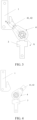
- FIG. 1 illustrates a perspective view of an electrical switch in accordance with at least one embodiment of the present disclosure.
- FIG. 2 illustrates a perspective view of an electrical switch according to at least one embodiment of the present disclosure, wherein a drive mechanism is omitted.
- FIG. 3 illustrates a side view of an electrical switch according to at least one embodiment of the present disclosure, wherein the movable contact assembly is in a first close position.
- FIG. 4 illustrates a side view of an electrical switch according to at least one embodiment of the present disclosure, wherein the movable contact assembly is in a disconnect position.
- FIG. 5 illustrates a cross-sectional view taken along the line A-A of FIG. 3 .
- FIG. 6 illustrates a schematic view of a movable contact according to at least one embodiment of the present disclosure.
- FIG. 7 illustrates a perspective view of an electrical switch in FIG. 3 with omitting a movable contact bracket.
- FIG. 8 illustrates a top view seen from the direction B of FIG. 7
- the electrical switch includes a first static contact 1, an outlet terminal 3, a movable contact assembly 4, and a drive mechanism 9.
- the main shaft 91 of the drive mechanism 9 acts as a power output source, transferring torque to the movable contact assembly 4.
- the main shaft 91 may include a drive shaft and an inner spline around the drive shaft, correspondingly, a movable contact assembly 4, specifically the movable contact bracket 8 of the movable contact assembly 4 may include an outer spline that mates with the inner spline, and a hole housing the drive shaft.
- the movable contact assembly 4 cooperates with the main shaft 91 (the dotted line illustrates the mode of power transmission for this cooperation) to transmit torque. Accordingly, as shown in FIG. 2 , the movable contact assembly 4 can rotate about the rotation axis D, thereby enabling a switching of positions between the first close position and the disconnect position.
- the first static contact 1 may be electrically connected to an inlet terminal, the inlet terminal may be electrically connected to a power supply, the outlet terminal 3 may be electrically connected to the outlet terminal, and the outlet terminal may be electrically connected to a load, for example.
- the housing of the electrical switch is omitted in the present disclosure. It is readily known to those skilled in the art that the first static contact 1, the outlet terminal 3, the movable contact assembly 4, the drive mechanism 9, and the like can be housed in a housing made of an electrically insulating material.
- the movable contact assembly 4 includes at least one pair of movable contacts 41, 42 disposed opposite each other and extending along a longitudinal axis L.
- the longitudinal axis L defines the length direction of the movable contacts 41, 42 and may be perpendicular to the rotational axis D.
- the movable contacts 41, 42 may be substantially in the shape of a sheet-like strip, including a first portion 43 and a second portion 44, opposite each other along the longitudinal axis L, for contacting the first static contact 1 and the outlet terminal 3 respectively.
- the first portion 43 is in contact with the first static contact 1 in the first close position, as shown in FIG. 3 .
- the first portion 43 is disconnected from the first static contact 1 in the disconnect position, as shown in FIG. 4 .
- the second section 44 remains connection with the outlet terminal 3. Therefore, in the first close position, the current is conducted between the inlet terminal and the outlet terminal through the movable contacts 41 and 42, and in the disconnect position, the movable contacts 41 and 42 are disconnected from the first static contact 1, so the inlet terminal and the outlet terminal are disconnected.
- the rotation axis D passes through the second portion 44.
- Such arrangement has a significant advantage, in that the second portion 44 of the movable contacts 41, 42 remaining connections with and in contact with the outlet terminal 3 rotates around the rotating axis D at the same time, thus eliminating the need for the movable contacts 41, 42 to be flexibly connected to the outlet terminal 3.
- the length of the movable contact of the present disclosure is smaller than that of the movable contact, with both ends thereof electrically connected to the static contact respectively, of the double-break switch.
- the movable contact of the present disclosure is in direct contact with the outlet terminal, so as to avoid the additional resistance and rotation inertia, generated by the flexible connection following the rotation of the movable contact, to the movement of the movable contact.
- no need for soft connection will save more installation space, so that the size of the electrical switch can be reduced.
- the rotation axis D passing through the second portion 44 can also reduce the resistance of the closing and disconnecting process.
- d represents a force arm length equivalent to the resistance torque applied to the movable contacts 41, 42 due to the presence of resistance.
- d represents the absolute value rather than the direction of the above distance, so that the contact position of the second portion 44 with the outlet terminal 3 can be located above or below the rotation axis D along the longitudinal axis L.
- the resistance mainly comes from the frictional resistance generated by the contact between the first portion 43 and the second portion 44 of the movable contact 41, 42 and the first static contact 1 and the outlet terminal 3 during the closing and disconnecting process, and the direction of the resistance is along the tangent direction of the radius of rotation, so that a moment of resistance is generated at the rotational axis. Since the rotation axis D passes through the second portion 44, and the value of d can be very small, even zero, the resistance and resistance moment from the outlet terminal 3 are very small. Moreover, due to the reduction of the length of the movable contact, the resistance moment from the first static contact 1 is also reduced accordingly. Overall, the resistance of the closing and disconnecting process can be greatly reduced, so that the requirement for the driving force of the driving mechanism is low. In addition, due to the savings in the number and size of parts, the manufacturing cost of electrical switches is also reduced accordingly.
- the first static contact 1 may have a hook-like shape as shown in FIGS. 2-4 , i.e. comprising a linear portion and a first contact portion 11 formed in a hook-like shape, and be configured to contact the movable contacts 41, 42.
- the two opposing surfaces of the first contact portion 11 may be arranged as inclined surface, the thickness of which gradually increases in a direction away from the movable contacts 41, 42.
- FIG. 5 illustrates each of components of the movable contact assembly and connection relationships thereof. It should be noted that all section lines in the sectional view are omitted for clearer illustration.
- the movable contacts 41, 42 are mounted in the movable contact bracket 8 and disposed opposite to each other, which may include a pair of mounting grooves 83 to accommodate the movable contacts 41, 42, which are separated by a dividing wall 84 of the movable contact bracket 8.
- the movable contacts 41, 42 may include protruding intermediate portions 46 (shown in FIG. 6 ) separated by the dividing wall 84.
- the movable contact assembly 4 may include an elastic assembly 7 applying a pressing force to the movable contacts 41, 42, and when the movable contacts 41, 42 are mounted in the movable contact bracket 8 but not in contact with the first static contact 1 or the outlet terminal 3, the intermediate portion 46 abuts against the dividing wall 84 and is separated by the dividing wall 84 under the pressing force of the elastic assembly 7.
- the first portion 43 and the second portion 44 as free ends, can be in contact with the first static contact 1 and the outlet terminal 3, respectively.
- the second portion 44 contacts and clamps the outlet terminal 3 but the first portion 43 does not contact the first static contact 1, the second portion 44 is pushed apart in a substantially V-shaped.
- the intermediate portion 46 is separated from the dividing wall 84 and the movable contacts 41, 42 are substantially parallel to each other.
- the movable contact bracket 8 may be made of an electrically insulating material, such as plastic.
- the first end 81 of the movable contact bracket 8 may be provided with an outer spline and a shaft hole for transmission connection with the main shaft 91 of the drive mechanism 9, and the second end 82 may be provided with an inner spline and a shaft similar to the main shaft 91 of the drive mechanism 9.
- This arrangement enhances the scalability of the movable contact bracket 8, i.e., another movable contact bracket 8' may be coaxially connected to the second end 82 of the movable contact bracket 8, thereby transmitting torque between the main shaft 91, the movable contact bracket 8, and the movable contact bracket 8'.
- such transmission can be continued by increasing the number of movable contact brackets 8.
- the movable contacts 41, 42 may have the same structure with mirror symmetry, so that the description of the movable contacts 41, 42 can only take one of the movable contacts as an example, and the other of a pair of movable contacts can be inferred.
- the first portion 43 of the movable contacts 41, 42 include first inner surfaces 5 opposite each other when the movable contacts 41, 42 are mounted in the movable contact bracket 8.
- the first inner surface 5 includes a first contact protrusion 51. In the first close position, as shown in FIGS. 5 and 6 , the first static contact 1 is in contact with the first contact protrusion 51 and clamped between the opposing first contact protrusions 51.
- the first contact protrusion 51 may have an oblique surface conforming to the first contact portion 11 of the first static contact 1, thus forming a surface contact with the first contact portion 11. Surface contact is advantageous and facilitates to reduce contact resistance.
- the second portion 44 of the movable contacts 41, 42 include second inner surfaces 6 opposite each other when the movable contacts 41, 42 are mounted in the movable contact bracket 8.
- the second inner surface 6 includes a second contact protrusion 61, and the outlet terminal 3 is in contact with the second contact protrusion 61 and clamped between the opposing second contact protrusions 61.
- the second contact protrusion 61 may be an arcuate protrusion, so that the contact position with the outlet terminal 3 is a small surface contact or point contact, which can reduce the frictional resistance of the movable contacts 41, 42 during rotation.
- Other modes of contact are also optional, such as surface contact between the outlet terminal 3 and the second contact protrusion 61, or point contact between the first static contact 1 and the first contact protrusion 51.
- the first static contact 1, the outlet terminal 3, and the movable contacts 41, 42 may be made of conductive material, such as pure copper. Silver may be coated at the contact positions of the movable contacts 41, 42 with the first static contact 1 and the outlet terminal 3. Silver coating can reduce contact resistance and protect copper from oxidation.
- the rotation axis D is adjacent to the second contact protrusion 61, that is, the value of d is small, e.g., less than 10 mm, less than 5 mm, less than 3 mm, less than 2 mm, or less than 1 mm.
- the rotation axis D passes through the second contact protrusion 61, that is, the contact position of the second contact protrusion 61 with the outlet terminal 3 coincides with the rotation axis D, so that the resistance of the rotation of the movable contacts 41, 42 can be minimized.
- the opposing surfaces may be referred to as inner surfaces, while surfaces reversed to the inner surfaces may be referred to as an outer surface.
- the movable contacts 41, 42 include an outer surface 45, and the elastic assembly 7 is attached to the outer surface 45 and configured to apply a pressing force to the movable contacts 41, 42.
- the elastic assembly 7 includes elastic parts 71 and a holder 72.
- the elastic parts 71 extend in the longitudinal direction L and are disposed on the outer surfaces 45 of the movable contacts 41, 42, respectively.
- the holder 72 is provided around the elastic parts 71 to hold the elastic parts 71 on the movable contacts 41, 42.
- the outer surfaces 45 of the movable contacts 41, 42 may include two mounting protrusions 47 protruding outward from the outer surface 45 of the first portion 43 and the outer surface 45 of the second portion 44, respectively.
- the two ends of the elastic part 71 are respectively abutted against to the mounting protrusions 47, which limit the movement of the two ends of the elastic part 71 in the longitudinal direction L, thereby attaching the elastic part 71 to the outer surface 45.
- the number of mounting protrusions 47 can be selected as needed, and the present disclosure is not limited thereto.
- the elastic part 71 is a leaf spring.
- the elastic part 71 may also be other elastic elements, such as a spiral spring and the like.
- the holder 72 may comprise clamping structure or a screw-fixing structure by means of which the holder 72 and the elastic part 71 are connected fixedly to compress the elastic part 71 oppositely.
- the holder 72 exerts a pressing force F1 on the elastic part 71, the direction of which is shown in FIG. 8.
- FIG. 8 only illustrates the force on the movable contact 42 and the elastic part 71 thereon as an example, and the force on the movable contact 41 is mirror-symmetrical.
- the distance of the engagement position of the holder 72 and the elastic part 71 from the contact position of the first portion 43 with the first static contact 1 is s1, and the distance from the contact position of the second portion 44 with the outlet terminal 3 is s2. That is, the pressure F2 applied by the movable contacts 41, 42 to the first static contact 1 is at a distance of s1 from the pressing force F1, and the pressure F3 applied by the movable contacts 41, 42 to the outlet terminal 3 is at a distance of s2 from the pressing force F1.
- s1 is greater than s2.
- the engagement position of the holder 72 and the elastic part 71 is closer to the contact position of the second portion 44 with the outlet terminal 3, comparing to the contact position of the first portion 43 with the first static contact 1.
- the pressing force F1 acts on the second portion 44 with a greater component, so the contact pressure F3 of the second portion 44 with the outlet terminal 3 in the contact position is greater than the contact pressure of the first portion 43 with the first static contact 1 in the contact position, which reduces the switch closing and breaking resistance.
- While the greater contact pressure of the second portion 44 with the outlet terminal 3 in the contact position can reduce the contact resistance (that is, the resistance of the entire circuit), thereby reducing the heating when the current passes through, which may ensure a only lower temperature rise when the current pass through the movable contact 41, 42 and the outlet terminal 3 for a long time.
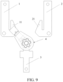
- FIG. 9 illustrates a side view of an electrical switch in accordance with another embodiment of the present disclosure.
- FIG. 10 illustrates a perspective view of a three-phase, four-wire electrical switch in accordance with yet another embodiment of the present disclosure.
- FIG. 11 illustrates a perspective view of a three-phase, four-wire electrical switch in accordance with another embodiment of the present disclosure.
- the electrical switch may be expanded in a modular manner.
- the electrical switch may be a dual power transfer switch, including a first static contact 1, a second static contact 2, an outlet terminal 3, and a movable contact assembly 4.
- the first static contact 1 and the second static contact 2 are disposed on both sides of the movable contact assembly 4, respectively, and the movable contact assembly is configured to rotate about the rotational axis D between the first close position, the second close position, and the disconnect position.
- the first portion 43 In the first closing position, the first portion 43 is in contact with the first static contact 1, in the second closing position, the first portion 43 is in contact with the second static contact 2, and in the disconnect position between the first closing position and the second closing position, the first portion 43 is disconnected from the first static contact 1 and the second static contact 2.
- the second portion 44 remains connected to the outlet terminal 3.
- the first static contact 1 may be connected to a first inlet terminal which is connected to a first power source (e.g., a main power source), and the second static contact 2 may be connected to a second inlet terminal which is connected to a second power source (e.g., a backup power source), and the outlet terminal 3 may be connected to the outlet terminal which is connected to a load. Therefore, the dual power switching function of switching between two power supplies can be realized with only one set of inlet terminals added.
- a first power source e.g., a main power source
- a second power source e.g., a backup power source
- FIG. 10 illustrates a perspective view of a three-phase, four-wire electrical switch (also referred to as 4P) in accordance with yet another embodiment of the present disclosure.
- the electrical switch comprises four sets of first static contacts 1, second static contacts 2, outlet terminals 3, and movable contacts assembly 4 arranged in parallel, with adjacent movable contacts assembly 4 rotating synchronously by transmitting torque through movable contact brackets 8 coaxially arranged.
- FIG. 11 illustrates a perspective view of a three-phase, four-wire electrical switch in accordance with another embodiment of the present disclosure. It is different from the embodiment shown in FIG. 10 that each set of the first static contact 1, the second static contact 2, and the outlet terminal 3 of the present embodiment are respectively connected with the two movable contact assemblies 4, 4'.
- the first static contact 1 includes a first sub-branch 12 and a second sub-branch 13 connected to each other
- the second static contact 2 includes a third sub-branch 22 and a fourth sub-branch 23 connected to each other.
- the movable contact assembly 4 is configured to contact with the first sub-branch 12 and the third sub-branch 22, and the movable contact assembly 4'is configured to contact with the second sub-branch 13 and the fourth sub-branch 23.
- the outlet terminal 3 may include a first terminal 31 and a second terminal 32 interconnected, with the movable contact assembly 4 connected to the first terminal 31, and the movable contact assembly 4'connected to the second terminal 32.
- FIG. 11 only identifies a set of static contacts 1, a first static contact 1, a second static contact 2, an outlet terminal 3, and two movable contact assemblies 4, 4', to which the connection relationships of the other three sets of components are similar so don't repeat herein.
- the rated flow capacity can be improved through the static contact and the movable contact group in parallel, forming a switch of a greater current level.
- the number of parallel elements can be increased as needed, and the two parallel element sets shown in FIG. 11 are only as an example.
Landscapes
- Physics & Mathematics (AREA)
- Electromagnetism (AREA)
- Details Of Connecting Devices For Male And Female Coupling (AREA)
- Rotary Switch, Piano Key Switch, And Lever Switch (AREA)
- Lock And Its Accessories (AREA)
- Air Bags (AREA)
- Oscillators With Electromechanical Resonators (AREA)
Abstract
Description
- The present application claims priority of the
Chinese Patent Application No. 202210374173.4, filed on April 11, 2022 - The present invention relates to an electrical switch.
- The electrical switch typically includes a contact structure consisting of a static contact and a movable contact, the movable contact being able to move relative to the static contact, contacting the static contact in the close position, and disconnecting to the static contact in the disconnect position.
- The plug-in contact structure is a common contact form. When the movable contact and the static contact are in contact, a pair of movable contacts clamp the static contacts under the action of the contact spring. According to the number of static contacts contacted by movable contacts at the same time, the switches with the plug-in contact structure can be divided into double-break switches and single-break switches.
- When the double-break switch is closed, the two ends of the movable contact clamp the first static contact connected to the inlet terminal and the second static contact connected to the outlet terminal, respectively, so that the current is conducted between the inlet terminal and the outlet terminal. However, when closing and disconnecting, it is necessary to overcome the friction caused by the clamping between the movable contact and the two static contacts, and the requirement for power source (such as the operating mechanism, manpower, etc.) used to drive the switch action is higher, and greater force is required to close or disconnect it.
- The movable contact of the single-break switch is connected to the outlet terminal through a flexible connection, such as by a copper braided wire, and when the switch is closed, the current can be conducted between the inlet terminal and the outlet terminal. This structure has a certain reduction in the resistance force of closing and disconnecting compared to the double-break switch. However, the flexible connection (copper braided wire), which is conductive and has certain elasticity, between the movable contact and the outlet terminal can bend and deform in a certain range to ensure the contact can move. However, when the movable contact rotates, this kind of flexible connection will follow the rotation, which will cause a certain resistance to the contact movement, and the flexible connection will also take up more space, making the switch size larger.
- Therefore, a new type of electrical switch with compact structure, low disconnection resistance force, low cost and high scalability is required.
- In response to the problems and requirements mentioned above, the present invention proposes a new type of electrical switch and a method of disconnecting the electrical switch, which solves the above problems and brings other technical effects by adopting the following technical features.
- In one aspect, the present disclosure provides an electrical switch, comprising: a first static contact, an outlet terminal, and movable contact assembly, the movable contact assembly connected to the outlet terminal and configured to rotate between a first close position and a disconnect position about a rotation axis, the movable contact assembly comprising at least one pair of movable contacts disposed opposite each other and extending along a longitudinal axis, wherein the at least one pair of movable contacts comprise first portion and second portion opposite each other along the longitudinal axis, the first portion contacting the first static contact in the first close position and disconnected from the first static contact in the disconnect position, the second portion remaining connected to the outlet terminal, and wherein the rotation axis passes through the second portion.
- In some examples, the first portion of the at least one pair of movable contacts comprise first inner surfaces opposite each other, the first inner surface comprising a first contact protrusion, and in the first close position, the first static contact is in contact with the first contact protrusion and clamped between the opposite first contact protrusions.
- In some examples, the second portion of the at least one pair of movable contacts comprise second inner surfaces opposite each other, the second inner surface comprising a second contact protrusion, and the outlet terminal is in contact with the second contact protrusion and clamped between the opposing second contact protrusions.
- In some examples, the rotation axis is adjacent to the second contact protrusion.
- In some examples, the rotation axis passes through the second contact protrusion.
- In some examples, the movable contact assembly further comprises an elastic assembly, the at least one pair of movable contacts further comprising outer surfaces opposite the first inner surfaces and the second inner surfaces, the elastic assembly attached to the outer surfaces and configured to apply a pressing force to the at least one pair of movable contacts.
- In some examples, the elastic assembly comprises elastic parts and a holder, the elastic parts extending in the longitudinal direction and disposed on outer surfaces of the at least one pair of movable contacts respectively, the holder disposed around the elastic parts to hold the elastic parts on the at least one pair of movable contacts.
- In some examples, the outer surfaces of the at least one pair of movable contacts comprise a plurality of mounting protrusions, the mounting protrusions protruding outwardly from outer surfaces of the first portion and outer surfaces of the second portion, respectively, with the ends of the elastic part abutted against the mounting protrusions.
- In some examples, the holder is fixedly connected with the elastic parts at an engagement position, and the distance of the engagement position from a contact position of the first portion and the first static contact is greater than the distance of the engagement position from a contact position of the second portion and the outlet terminal.
- In some examples, the elastic part is a leaf spring.
- In some examples, the movable contact assembly further comprises a rotatable movable contact bracket connected to a drive mechanism of the electrical switch to rotate about the rotation axis under the actuation of the drive mechanism the at least one pair of movable contacts is disposed in the movable contact bracket.
- In some examples, the electrical switch further comprises a second static contact, the movable contact assembly further configured to rotate about the rotation axis between a first close position, a second close position, and a disconnect position, the first portion contacting the second static contact in the second close position.
- In some examples, the electrical switch further comprises a second movable contact assembly coaxially connected with and in drive connection with the movable contact assembly, wherein the first static contact comprises a first sub-branch and a second sub-branch connected to each other, the second static contact comprises a third sub-branch and a fourth sub-branch connected to each other, the movable contact assembly is configured to contact with the first sub-branch and the third sub-branch, and the second movable contact assembly is configured to contact with the second sub-branch and the fourth sub-branch.
- In some examples, the outlet terminal comprises a first terminal and a second terminal connected to each other, the movable contact assembly connected to the first terminal, and the second movable contact assembly connected to the second terminal.
- In some examples, the electrical switch is a dual power transfer switch.
- In order to more clearly illustrate technical solutions of the embodiments of the present disclosure, the accompanying drawings of the embodiments will be introduced briefly below. It is apparent that the accompanying drawings in the following description only relate to some embodiments of the present disclosure and are not intended to limit the present disclosure.
-
FIG. 1 illustrates a perspective view of an electrical switch in accordance with at least one embodiment of the present disclosure; -
FIG. 2 illustrates a perspective view of an electrical switch according to at least one embodiment of the present disclosure, wherein a drive mechanism is omitted; -
FIG. 3 illustrates a side view of an electrical switch according to at least one embodiment of the present disclosure, wherein the movable contact assembly is in a first close position; -
FIG. 4 illustrates a side view of an electrical switch according to at least one embodiment of the present disclosure, wherein the movable contact assembly is in a disconnect position; -
FIG. 5 illustrates a cross-sectional view taken along the line A-A ofFIG. 3 ; -
FIG. 6 illustrates a schematic view of a movable contact according to at least one embodiment of the present disclosure; -
FIG. 7 illustrates a perspective view of an electrical switch inFIG. 3 with omitting a movable contact bracket; -
FIG. 8 illustrates a top view seen from the direction B ofFIG. 7 ; -
FIG. 9 illustrates a side view of an electrical switch in accordance with another embodiment of the present disclosure; -
FIG. 10 illustrates a perspective view of a three-phase, four-wire electrical switch in accordance with yet another embodiment of the present disclosure; -
FIG. 11 illustrates a perspective view of a three-phase, four-wire electrical switch in accordance with another embodiment of the present disclosure. -
- 1
- first static contact
- 11
- first contact portion
- 12
- first sub-branch
- 13
- second sub-branch
- 2
- second static contact
- 21
- second contact portion
- 22
- third sub-branch
- 23
- fourth sub-branch
- 3
- outlet terminal
- 31
- first terminal
- 32
- second terminal
- 4, 4'
- movable contact assembly
- 41, 42
- movable contact
- 43
- first portion
- 44
- second portion
- 45
- outer surface
- 46
- intermediate portion
- 47
- mounting protrusion
- 5
- first inner surface
- 51
- first contact protrusion
- 6
- second inner surface
- 61
- second contact protrusion
- 7
- elastic assembly
- 71
- elastic part
- 72
- holder
- 8, 8'
- movable contact bracket
- 81
- first end
- 82
- second end
- 83
- mounting groove
- 84
- dividing wall
- 9
- drive mechanism
- 91
- main shaft
- D
- rotation axis
- L
- longitudinal axis
- In order to make objects, technical solutions, and advantages of the embodiments of the present disclosure more apparent, the technical solutions of the embodiments of the present disclosure will be described in a clearly and fully understandable way in connection with the drawings related to the embodiments of the present disclosure. It is apparent that the described embodiments are just a part but not all of the embodiments of the present disclosure. Based on the described embodiments of the present disclosure, those skilled in the art may obtain other embodiments, without any creative work, which shall be within the protection scope of the present disclosure .
- Unless otherwise defined, all the technical and scientific terms used in the present disclosure have the same meanings as commonly understood by one of ordinary skill in the art to which the present disclosure belongs. The terms, such as "first," "second," or the like, which are used in the present disclosure, are not intended to indicate any sequence, amount or importance, but are merely used for distinguishing various components. Similarly, the terms such as "a," "an," or "the," etc., are not intended to limit the amount, but indicate the existence of at least one. The terms, such as "comprise/comprising," "include/including," or the like are intended to specify that the elements or the objects stated before these terms encompass the elements or the objects and equivalents thereof listed after these terms, but not preclude other elements or objects. The phrases, such as "connect/connecting/connected," "couple/coupling/coupled" or the like, are not intended to define a physical connection or mechanical connection, but may comprise an electrical connection/coupling, directly or indirectly. The terms, "on," "under," "left," "right," or the like are only used to indicate relative position relationship, and when the absolute position of the object which is described is changed, the relative position relationship may be changed accordingly.
- Each of embodiments according to the present invention will be described with reference to the drawings. Herein, it is to be noted that the same reference numerals are given to components having substantially the same or similar structures and functions in the drawings, and duplicate descriptions of them will be omitted.
- A feasible embodiment within the scope of protection of the present disclosure may have fewer components, other components not shown in the drawings, different components, differently arranged components, or differently connected components, etc. than the embodiments shown in the drawings. Further, two or more of the components in the drawings may be implemented in a single component, or the single component shown in the drawings may be implemented as a plurality of separate components, without departing from the concepts of the present disclosure.
- For the sake of description, components commonly used in the art, such as the housing of an electrical switch, an inlet terminal, an outlet terminal, a dividing unit, and other components not related to the description of the present disclosure, are simplified or omitted accordingly in the drawings. These omitted or simplified components do not affect the understanding of the contents of the present disclosure by those skilled in the art.
- The resistance force of electrical switch with plug-in contact structure is one of the important parameters to evaluate the electrical switch, which affects the required driving force of power source, such as operating mechanism, manpower, etc., driving the switch action. As described in the background art, existing electrical switches with a plug-in contact structure have many defects, especially in terms of closing and disconnecting resistance. For example, when the double-breaking switch is closed and disconnected, the friction generated by the clamping between the movable contact and the two static contacts needs to be overcome, while the single-breaking switch reduces one break compared to the double-breaking switch, so that the resistance to close and disconnect is reduced in a certain extent. However, the connection between the movable contact and the outlet terminal of the single-breaking switch uses a conductive flexible connection, copper braided wire, which can be bent and deformed within a certain range to ensure that the contact can move and also has a certain degree of elasticity. However, when the movable contact swings, such flexible connection will follow the swing, which will have a certain resistance to the movement of the contact and will increase the inertia of the contact. It means that a greater driving force is required to smoothly close or disconnect the switch. Flexible connection also takes up more space, increasing the size of electrical switch.
- In view of the defects of the prior art, the present disclosure proposes a new electrical switch. Hereinafter, preferred embodiments of the electrical switch according to the present disclosure will be described in detail with reference to the accompanying drawings.
-
FIG. 1 illustrates a perspective view of an electrical switch in accordance with at least one embodiment of the present disclosure.FIG. 2 illustrates a perspective view of an electrical switch according to at least one embodiment of the present disclosure, wherein a drive mechanism is omitted.FIG. 3 illustrates a side view of an electrical switch according to at least one embodiment of the present disclosure, wherein the movable contact assembly is in a first close position.FIG. 4 illustrates a side view of an electrical switch according to at least one embodiment of the present disclosure, wherein the movable contact assembly is in a disconnect position.FIG. 5 illustrates a cross-sectional view taken along the line A-A ofFIG. 3 .FIG. 6 illustrates a schematic view of a movable contact according to at least one embodiment of the present disclosure.FIG. 7 illustrates a perspective view of an electrical switch inFIG. 3 with omitting a movable contact bracket.FIG. 8 illustrates a top view seen from the direction B ofFIG. 7 . - As shown in
FIG. 1 , the electrical switch according to at least one embodiment of the present disclosure includes a firststatic contact 1, anoutlet terminal 3, amovable contact assembly 4, and adrive mechanism 9. Themain shaft 91 of thedrive mechanism 9 acts as a power output source, transferring torque to themovable contact assembly 4. For example, themain shaft 91 may include a drive shaft and an inner spline around the drive shaft, correspondingly, amovable contact assembly 4, specifically themovable contact bracket 8 of themovable contact assembly 4 may include an outer spline that mates with the inner spline, and a hole housing the drive shaft. Themovable contact assembly 4 cooperates with the main shaft 91 (the dotted line illustrates the mode of power transmission for this cooperation) to transmit torque. Accordingly, as shown inFIG. 2 , themovable contact assembly 4 can rotate about the rotation axis D, thereby enabling a switching of positions between the first close position and the disconnect position. - The first
static contact 1 may be electrically connected to an inlet terminal, the inlet terminal may be electrically connected to a power supply, theoutlet terminal 3 may be electrically connected to the outlet terminal, and the outlet terminal may be electrically connected to a load, for example. - For the sake of description, the housing of the electrical switch is omitted in the present disclosure. It is readily known to those skilled in the art that the first
static contact 1, theoutlet terminal 3, themovable contact assembly 4, thedrive mechanism 9, and the like can be housed in a housing made of an electrically insulating material. - As shown in
FIGS. 2-5 , themovable contact assembly 4 includes at least one pair ofmovable contacts movable contacts movable contacts first portion 43 and asecond portion 44, opposite each other along the longitudinal axis L, for contacting the firststatic contact 1 and theoutlet terminal 3 respectively. - Specifically, the
first portion 43 is in contact with the firststatic contact 1 in the first close position, as shown inFIG. 3 . Thefirst portion 43 is disconnected from the firststatic contact 1 in the disconnect position, as shown inFIG. 4 . Thesecond section 44 remains connection with theoutlet terminal 3. Therefore, in the first close position, the current is conducted between the inlet terminal and the outlet terminal through themovable contacts movable contacts static contact 1, so the inlet terminal and the outlet terminal are disconnected. - In this embodiment, the rotation axis D passes through the
second portion 44. Such arrangement has a significant advantage, in that thesecond portion 44 of themovable contacts outlet terminal 3 rotates around the rotating axis D at the same time, thus eliminating the need for themovable contacts outlet terminal 3. Direct connection between theoutlet terminal 3 and themovable contacts - Not only that, the rotation axis D passing through the
second portion 44 can also reduce the resistance of the closing and disconnecting process. As shown inFIG. 5 , it is assumed that the distance of the contact position of thesecond part 44 with theoutlet terminal 3 from the rotation axis D along thelongitudinal axis 1 is d. It should be noted that since the contact portion of thesecond portion 44 with theoutlet terminal 3 may be a point contact or a surface contact, d represents a force arm length equivalent to the resistance torque applied to themovable contacts second portion 44 with theoutlet terminal 3 can be located above or below the rotation axis D along the longitudinal axis L. The resistance mainly comes from the frictional resistance generated by the contact between thefirst portion 43 and thesecond portion 44 of themovable contact static contact 1 and theoutlet terminal 3 during the closing and disconnecting process, and the direction of the resistance is along the tangent direction of the radius of rotation, so that a moment of resistance is generated at the rotational axis. Since the rotation axis D passes through thesecond portion 44, and the value of d can be very small, even zero, the resistance and resistance moment from theoutlet terminal 3 are very small. Moreover, due to the reduction of the length of the movable contact, the resistance moment from the firststatic contact 1 is also reduced accordingly. Overall, the resistance of the closing and disconnecting process can be greatly reduced, so that the requirement for the driving force of the driving mechanism is low. In addition, due to the savings in the number and size of parts, the manufacturing cost of electrical switches is also reduced accordingly. - Optionally, the first
static contact 1 may have a hook-like shape as shown inFIGS. 2-4 , i.e. comprising a linear portion and afirst contact portion 11 formed in a hook-like shape, and be configured to contact themovable contacts first contact portion 11 may be arranged as inclined surface, the thickness of which gradually increases in a direction away from themovable contacts movable contacts static contact 1 can be reduced, but also the contact (a smaller thickness position) of themovable contacts static contact 1 can be guided to ensure a reliable contact (a larger thickness position) of thecontacts static contact 1 in the first closing position. - The cross-sectional view of
FIG. 5 illustrates each of components of the movable contact assembly and connection relationships thereof. It should be noted that all section lines in the sectional view are omitted for clearer illustration. Themovable contacts movable contact bracket 8 and disposed opposite to each other, which may include a pair of mountinggrooves 83 to accommodate themovable contacts wall 84 of themovable contact bracket 8. Specifically, themovable contacts FIG. 6 ) separated by the dividingwall 84. Themovable contact assembly 4 may include anelastic assembly 7 applying a pressing force to themovable contacts movable contacts movable contact bracket 8 but not in contact with the firststatic contact 1 or theoutlet terminal 3, theintermediate portion 46 abuts against the dividingwall 84 and is separated by the dividingwall 84 under the pressing force of theelastic assembly 7. Thefirst portion 43 and thesecond portion 44, as free ends, can be in contact with the firststatic contact 1 and theoutlet terminal 3, respectively. When thesecond portion 44 contacts and clamps theoutlet terminal 3 but thefirst portion 43 does not contact the firststatic contact 1, thesecond portion 44 is pushed apart in a substantially V-shaped. When thefirst portion 43 and thesecond portion 44 are in contact with and clamped to theoutlet terminal 3, respectively, theintermediate portion 46 is separated from the dividingwall 84 and themovable contacts - The
movable contact bracket 8 may be made of an electrically insulating material, such as plastic. - The
first end 81 of themovable contact bracket 8 may be provided with an outer spline and a shaft hole for transmission connection with themain shaft 91 of thedrive mechanism 9, and thesecond end 82 may be provided with an inner spline and a shaft similar to themain shaft 91 of thedrive mechanism 9. This arrangement enhances the scalability of themovable contact bracket 8, i.e., another movable contact bracket 8' may be coaxially connected to thesecond end 82 of themovable contact bracket 8, thereby transmitting torque between themain shaft 91, themovable contact bracket 8, and the movable contact bracket 8'. Similarly, such transmission can be continued by increasing the number ofmovable contact brackets 8. - The
movable contacts movable contacts FIG. 6 , thefirst portion 43 of themovable contacts inner surfaces 5 opposite each other when themovable contacts movable contact bracket 8. The firstinner surface 5 includes afirst contact protrusion 51. In the first close position, as shown inFIGS. 5 and 6 , the firststatic contact 1 is in contact with thefirst contact protrusion 51 and clamped between the opposingfirst contact protrusions 51. Thefirst contact protrusion 51 may have an oblique surface conforming to thefirst contact portion 11 of the firststatic contact 1, thus forming a surface contact with thefirst contact portion 11. Surface contact is advantageous and facilitates to reduce contact resistance. In addition, thesecond portion 44 of themovable contacts inner surfaces 6 opposite each other when themovable contacts movable contact bracket 8. The secondinner surface 6 includes asecond contact protrusion 61, and theoutlet terminal 3 is in contact with thesecond contact protrusion 61 and clamped between the opposingsecond contact protrusions 61. Thesecond contact protrusion 61 may be an arcuate protrusion, so that the contact position with theoutlet terminal 3 is a small surface contact or point contact, which can reduce the frictional resistance of themovable contacts outlet terminal 3 and thesecond contact protrusion 61, or point contact between the firststatic contact 1 and thefirst contact protrusion 51. - The first
static contact 1, theoutlet terminal 3, and themovable contacts movable contacts static contact 1 and theoutlet terminal 3. Silver coating can reduce contact resistance and protect copper from oxidation. - Alternatively, the rotation axis D is adjacent to the
second contact protrusion 61, that is, the value of d is small, e.g., less than 10 mm, less than 5 mm, less than 3 mm, less than 2 mm, or less than 1 mm. In this embodiment, the rotation axis D passes through thesecond contact protrusion 61, that is, the contact position of thesecond contact protrusion 61 with theoutlet terminal 3 coincides with the rotation axis D, so that the resistance of the rotation of themovable contacts - It should be noted that the "inner" and "outer" described herein are relative to a pair of
movable contacts movable contact bracket 8, the opposing surfaces may be referred to as inner surfaces, while surfaces reversed to the inner surfaces may be referred to as an outer surface. - The
movable contacts outer surface 45, and theelastic assembly 7 is attached to theouter surface 45 and configured to apply a pressing force to themovable contacts FIGS. 5 and8 , theelastic assembly 7 includeselastic parts 71 and aholder 72. Theelastic parts 71 extend in the longitudinal direction L and are disposed on theouter surfaces 45 of themovable contacts holder 72 is provided around theelastic parts 71 to hold theelastic parts 71 on themovable contacts outer surfaces 45 of themovable contacts protrusions 47 protruding outward from theouter surface 45 of thefirst portion 43 and theouter surface 45 of thesecond portion 44, respectively. The two ends of theelastic part 71 are respectively abutted against to the mountingprotrusions 47, which limit the movement of the two ends of theelastic part 71 in the longitudinal direction L, thereby attaching theelastic part 71 to theouter surface 45. The number of mountingprotrusions 47 can be selected as needed, and the present disclosure is not limited thereto. In this embodiment, theelastic part 71 is a leaf spring. Alternatively, theelastic part 71 may also be other elastic elements, such as a spiral spring and the like. - As shown in
FIGS. 5 and8 , theholder 72 may comprise clamping structure or a screw-fixing structure by means of which theholder 72 and theelastic part 71 are connected fixedly to compress theelastic part 71 oppositely. At the engagement position of theholder 72 and theelastic part 71, theholder 72 exerts a pressing force F1 on theelastic part 71, the direction of which is shown inFIG. 8. FIG. 8 only illustrates the force on themovable contact 42 and theelastic part 71 thereon as an example, and the force on themovable contact 41 is mirror-symmetrical. - The distance of the engagement position of the
holder 72 and theelastic part 71 from the contact position of thefirst portion 43 with the firststatic contact 1 is s1, and the distance from the contact position of thesecond portion 44 with theoutlet terminal 3 is s2. That is, the pressure F2 applied by themovable contacts static contact 1 is at a distance of s1 from the pressing force F1, and the pressure F3 applied by themovable contacts outlet terminal 3 is at a distance of s2 from the pressing force F1. In this embodiment, s1 is greater than s2. In other words, the engagement position of theholder 72 and theelastic part 71 is closer to the contact position of thesecond portion 44 with theoutlet terminal 3, comparing to the contact position of thefirst portion 43 with the firststatic contact 1. According to the force analysis, since s1 is greater than s2, the pressing force F1 acts on thesecond portion 44 with a greater component, so the contact pressure F3 of thesecond portion 44 with theoutlet terminal 3 in the contact position is greater than the contact pressure of thefirst portion 43 with the firststatic contact 1 in the contact position, which reduces the switch closing and breaking resistance. While the greater contact pressure of thesecond portion 44 with theoutlet terminal 3 in the contact position can reduce the contact resistance (that is, the resistance of the entire circuit), thereby reducing the heating when the current passes through, which may ensure a only lower temperature rise when the current pass through themovable contact outlet terminal 3 for a long time. -
FIG. 9 illustrates a side view of an electrical switch in accordance with another embodiment of the present disclosure.FIG. 10 illustrates a perspective view of a three-phase, four-wire electrical switch in accordance with yet another embodiment of the present disclosure.FIG. 11 illustrates a perspective view of a three-phase, four-wire electrical switch in accordance with another embodiment of the present disclosure. - The electrical switch according to at least one embodiment of the present disclosure may be expanded in a modular manner. For example, as shown in
FIG. 9 , the electrical switch may be a dual power transfer switch, including a firststatic contact 1, a secondstatic contact 2, anoutlet terminal 3, and amovable contact assembly 4. The firststatic contact 1 and the secondstatic contact 2 are disposed on both sides of themovable contact assembly 4, respectively, and the movable contact assembly is configured to rotate about the rotational axis D between the first close position, the second close position, and the disconnect position. In the first closing position, thefirst portion 43 is in contact with the firststatic contact 1, in the second closing position, thefirst portion 43 is in contact with the secondstatic contact 2, and in the disconnect position between the first closing position and the second closing position, thefirst portion 43 is disconnected from the firststatic contact 1 and the secondstatic contact 2. As in the aforementioned embodiments, thesecond portion 44 remains connected to theoutlet terminal 3. The firststatic contact 1 may be connected to a first inlet terminal which is connected to a first power source (e.g., a main power source), and the secondstatic contact 2 may be connected to a second inlet terminal which is connected to a second power source (e.g., a backup power source), and theoutlet terminal 3 may be connected to the outlet terminal which is connected to a load. Therefore, the dual power switching function of switching between two power supplies can be realized with only one set of inlet terminals added. -
FIG. 10 illustrates a perspective view of a three-phase, four-wire electrical switch (also referred to as 4P) in accordance with yet another embodiment of the present disclosure. The electrical switch comprises four sets of firststatic contacts 1, secondstatic contacts 2,outlet terminals 3, andmovable contacts assembly 4 arranged in parallel, with adjacentmovable contacts assembly 4 rotating synchronously by transmitting torque throughmovable contact brackets 8 coaxially arranged. -
FIG. 11 illustrates a perspective view of a three-phase, four-wire electrical switch in accordance with another embodiment of the present disclosure. It is different from the embodiment shown inFIG. 10 that each set of the firststatic contact 1, the secondstatic contact 2, and theoutlet terminal 3 of the present embodiment are respectively connected with the twomovable contact assemblies 4, 4'. For example, the firststatic contact 1 includes afirst sub-branch 12 and asecond sub-branch 13 connected to each other, and the secondstatic contact 2 includes athird sub-branch 22 and afourth sub-branch 23 connected to each other. Themovable contact assembly 4 is configured to contact with thefirst sub-branch 12 and thethird sub-branch 22, and the movable contact assembly 4'is configured to contact with thesecond sub-branch 13 and thefourth sub-branch 23. - Correspondingly, the
outlet terminal 3 may include afirst terminal 31 and asecond terminal 32 interconnected, with themovable contact assembly 4 connected to thefirst terminal 31, and the movable contact assembly 4'connected to thesecond terminal 32. -
FIG. 11 only identifies a set ofstatic contacts 1, a firststatic contact 1, a secondstatic contact 2, anoutlet terminal 3, and twomovable contact assemblies 4, 4', to which the connection relationships of the other three sets of components are similar so don't repeat herein. - According to the above embodiment, the rated flow capacity can be improved through the static contact and the movable contact group in parallel, forming a switch of a greater current level. The number of parallel elements can be increased as needed, and the two parallel element sets shown in
FIG. 11 are only as an example. - The exemplary embodiments of the present invention have been described in detail above with reference to the preferred embodiments. However, those skilled in the art can understand that, without departing from the concept of the present invention, various modifications can be made to the above-mentioned specific embodiments. For example, the structure of the electrical switch is also suitable for dual power transfer switches of 2P, 3P, and 4P. In addition, variations and modifications, and various combinations of various technical features and structures proposed by the present invention can be made without exceeding the protection scope of the present invention, which is determined by the appended claims.
Claims (15)
- An electrical switch, comprising:a first static contact;an outlet terminal; anda movable contact assembly connected to the outlet terminal and configured to rotate between a first close position and a disconnect position about a rotation axis, the movable contact assembly comprising at least one pair of movable contacts disposed opposite each other and extending along a longitudinal axis,wherein the at least one pair of movable contacts comprise first portion and second portion opposite each other along the longitudinal axis, the first portion contacting the first static contact in the first close position and disconnected from the first static contact in the disconnect position, the second portion remaining connected to the outlet terminal, andwherein the rotation axis passes through the second portion.
- The electrical switch according to claim 1, wherein the first portion of the at least one pair of movable contacts comprise first inner surfaces opposite each other, the first inner surface comprising a first contact protrusion, and in the first close position, the first static contact is in contact with the first contact protrusion and clamped between the opposite first contact protrusions.
- The electrical switch according to claim 2, wherein the second portion of the at least one pair of movable contacts comprise second inner surfaces opposite each other, the second inner surface comprising a second contact protrusion, and the outlet terminal is in contact with the second contact protrusion and clamped between the opposing second contact protrusions.
- The electrical switch according to claim 3, wherein the rotation axis is adjacent to the second contact protrusion.
- The electrical switch according to claim 3, wherein the rotation axis passes through the second contact protrusion.
- The electrical switch of claim 3, wherein the movable contact assembly further comprises an elastic assembly, the at least one pair of movable contacts further comprising outer surfaces opposite the first inner surfaces and the second inner surfaces, the elastic assembly attached to the outer surfaces and configured to apply a pressing force to the at least one pair of movable contacts.
- The electrical switch according to claim 6, wherein the elastic assembly comprises elastic parts and a holder, the elastic parts extending in the longitudinal direction and disposed on outer surfaces of the at least one pair of movable contacts respectively, the holder disposed around the elastic parts to hold the elastic parts on the at least one pair of movable contacts.
- The electrical switch according to claim 7, wherein the outer surfaces of the at least one pair of movable contacts comprise a plurality of mounting protrusions, the mounting protrusions protruding outwardly from outer surface of the first portion and outer surface of the second portion, respectively, with the ends of the elastic part abutted against the mounting protrusions.
- The electrical switch according to claim 7, wherein the holder is fixedly connected with the elastic parts at an engagement position, and the distance of the engagement position from a contact position of the first portion and the first static contact is greater than the distance of the engagement position from a contact position of the second portion and the outlet terminal.
- The electrical switch according to any one of claims 7 to 9, wherein the elastic part is a leaf spring.
- The electrical switch according to any one of claims 1 to 9, wherein the movable contact assembly further comprises a rotatable movable contact bracket connected to a drive mechanism of the electrical switch to rotate about the rotation axis under the actuation of the drive mechanism, wherein the at least one pair of movable contacts is disposed in the movable contact bracket.
- The electrical switch according to any one of claims 1 to 9, further comprising a second static contact, the movable contact assembly further configured to rotate about the rotation axis between a first close position, a second close position, and a disconnect position, the first portion contacting the second static contact in the second close position.
- The electrical switch according to claim 12, further comprising a second movable contact assembly coaxially connected with and in drive connection with the movable contact assembly, wherein the first static contact comprises a first sub-branch and a second sub-branch connected to each other, the second static contact comprises a third sub-branch and a fourth sub-branch connected to each other, the movable contact assembly is configured to contact with the first sub-branch and the third sub-branch, and the second movable contact assembly is configured to contact with the second sub-branch and the fourth sub-branch.
- The electrical switch according to claim 13, wherein the outlet terminal comprises a first terminal and a second terminal connected to each other, the movable contact assembly connected to the first terminal, and the second movable contact assembly connected to the second terminal.
- The electrical switch according to claim 12, wherein the electrical switch is a dual power transfer switch.
Applications Claiming Priority (1)
| Application Number | Priority Date | Filing Date | Title |
|---|---|---|---|
| CN202210374173.4A CN116936268A (en) | 2022-04-11 | 2022-04-11 | electrical switch |
Publications (1)
| Publication Number | Publication Date |
|---|---|
| EP4270431A1 true EP4270431A1 (en) | 2023-11-01 |
Family
ID=86226919
Family Applications (1)
| Application Number | Title | Priority Date | Filing Date |
|---|---|---|---|
| EP23305535.9A Pending EP4270431A1 (en) | 2022-04-11 | 2023-04-11 | Electrical switch |
Country Status (3)
| Country | Link |
|---|---|
| EP (1) | EP4270431A1 (en) |
| CN (1) | CN116936268A (en) |
| AU (1) | AU2023202215B2 (en) |
Cited By (1)
| Publication number | Priority date | Publication date | Assignee | Title |
|---|---|---|---|---|
| CN117352328A (en) * | 2023-11-07 | 2024-01-05 | 浙江乾泰电气有限公司 | Load isolating switch |
Citations (9)
| Publication number | Priority date | Publication date | Assignee | Title |
|---|---|---|---|---|
| JPS6192330A (en) * | 1984-10-12 | 1986-05-10 | Yaskawa Electric Mfg Co Ltd | Composite spring and main circuit disconnection device using the same |
| EP0951030A2 (en) * | 1998-04-16 | 1999-10-20 | CO.E.P.T.E. COSTRUZIONI ELETTROMECCANICHE PER TRAZIONE ELETTRICA S.r.l. | Electric contact with twin-knife insertion coupling, particularly for disconnectors, switches or the like. |
| CN102290263A (en) * | 2011-08-08 | 2011-12-21 | 常熟开关制造有限公司(原常熟开关厂) | Moving contact unit |
| CN104335311A (en) | 2012-06-11 | 2015-02-04 | Abb有限公司 | current switching device |
| CN106165044A (en) | 2014-04-09 | 2016-11-23 | Abb瑞士股份有限公司 | Knife switch assembly, power distribution switchgear and method for preventing discharge |
| EP3226275A1 (en) | 2016-03-28 | 2017-10-04 | Siemens Aktiengesellschaft | Moving contact protective sleeve, contact module having same and isolating switch |
| CN208460584U (en) | 2018-05-24 | 2019-02-01 | 深圳市泰永电气科技有限公司 | Moving contact interpolar attachment device |
| EP3457422A1 (en) * | 2017-09-15 | 2019-03-20 | ABB Oy | An electrical switch |
| CN214956603U (en) | 2021-03-17 | 2021-11-30 | 上海正泰智能科技有限公司 | Switch device and rotary switch |
-
2022
- 2022-04-11 CN CN202210374173.4A patent/CN116936268A/en active Pending
-
2023
- 2023-04-11 EP EP23305535.9A patent/EP4270431A1/en active Pending
- 2023-04-11 AU AU2023202215A patent/AU2023202215B2/en active Active
Patent Citations (10)
| Publication number | Priority date | Publication date | Assignee | Title |
|---|---|---|---|---|
| JPS6192330A (en) * | 1984-10-12 | 1986-05-10 | Yaskawa Electric Mfg Co Ltd | Composite spring and main circuit disconnection device using the same |
| EP0951030A2 (en) * | 1998-04-16 | 1999-10-20 | CO.E.P.T.E. COSTRUZIONI ELETTROMECCANICHE PER TRAZIONE ELETTRICA S.r.l. | Electric contact with twin-knife insertion coupling, particularly for disconnectors, switches or the like. |
| CN102290263A (en) * | 2011-08-08 | 2011-12-21 | 常熟开关制造有限公司(原常熟开关厂) | Moving contact unit |
| CN104335311A (en) | 2012-06-11 | 2015-02-04 | Abb有限公司 | current switching device |
| CN106165044A (en) | 2014-04-09 | 2016-11-23 | Abb瑞士股份有限公司 | Knife switch assembly, power distribution switchgear and method for preventing discharge |
| CN106165044B (en) | 2014-04-09 | 2018-01-02 | Abb瑞士股份有限公司 | Knife switch assembly, power distribution switchgear and method for preventing discharge |
| EP3226275A1 (en) | 2016-03-28 | 2017-10-04 | Siemens Aktiengesellschaft | Moving contact protective sleeve, contact module having same and isolating switch |
| EP3457422A1 (en) * | 2017-09-15 | 2019-03-20 | ABB Oy | An electrical switch |
| CN208460584U (en) | 2018-05-24 | 2019-02-01 | 深圳市泰永电气科技有限公司 | Moving contact interpolar attachment device |
| CN214956603U (en) | 2021-03-17 | 2021-11-30 | 上海正泰智能科技有限公司 | Switch device and rotary switch |
Cited By (2)
| Publication number | Priority date | Publication date | Assignee | Title |
|---|---|---|---|---|
| CN117352328A (en) * | 2023-11-07 | 2024-01-05 | 浙江乾泰电气有限公司 | Load isolating switch |
| CN117352328B (en) * | 2023-11-07 | 2024-04-02 | 浙江乾泰电气有限公司 | Load isolating switch |
Also Published As
| Publication number | Publication date |
|---|---|
| AU2023202215A1 (en) | 2023-10-26 |
| CN116936268A (en) | 2023-10-24 |
| AU2023202215B2 (en) | 2024-05-02 |
Similar Documents
| Publication | Publication Date | Title |
|---|---|---|
| US4633118A (en) | Piezoelectrically actuated high-speed microwave switch | |
| US7189933B2 (en) | Solid insulated disconnection switch | |
| EP4270431A1 (en) | Electrical switch | |
| KR20000071862A (en) | Electrical apparatus having improved electrical contact and electrical contact used therewith | |
| CN217588715U (en) | Contact assembly, switch unit and switching device | |
| CN108666164B (en) | Rotary electrical switch contact system and rotary electrical switch | |
| CN114724895B (en) | Electromagnetic relay | |
| CN1146930C (en) | Electric contact device in electric switch | |
| US11742168B2 (en) | Operating mechanism of circuit breaker | |
| CN112117138A (en) | Electrical switch | |
| KR102707268B1 (en) | Elastic contact plate structure of electromagnetic relay | |
| CN211088097U (en) | Main loop single-pole device of automatic change-over switch electric appliance | |
| CN101896986A (en) | Circuit breaker for a switchgear | |
| CN213340263U (en) | Moving contact assemblies and electrical switches | |
| US6851972B2 (en) | Connector device and wiper drive motor having connector device | |
| CN214203477U (en) | Contact system with power-assisted opening | |
| RU2364827C1 (en) | Pyrotechnical switching device | |
| CN217507122U (en) | Single-breakpoint plug-in type electrical switch | |
| CN2251204Y (en) | Full-flat spring spring-pressing contact type current connector | |
| CN220106285U (en) | Neutral pole unit and automatic change-over switch | |
| CN221040927U (en) | Switch-on unit and disconnect switch | |
| CN222319995U (en) | Contact assembly, load switch and ammeter | |
| CN222380522U (en) | Conductive piece and miniature circuit breaker of installation | |
| CN223193720U (en) | Movable contact assembly and relay | |
| EP4465325A1 (en) | Contact part and relay |
Legal Events
| Date | Code | Title | Description |
|---|---|---|---|
| PUAI | Public reference made under article 153(3) epc to a published international application that has entered the european phase |
Free format text: ORIGINAL CODE: 0009012 |
|
| STAA | Information on the status of an ep patent application or granted ep patent |
Free format text: STATUS: THE APPLICATION HAS BEEN PUBLISHED |
|
| AK | Designated contracting states |
Kind code of ref document: A1 Designated state(s): AL AT BE BG CH CY CZ DE DK EE ES FI FR GB GR HR HU IE IS IT LI LT LU LV MC ME MK MT NL NO PL PT RO RS SE SI SK SM TR |
|
| STAA | Information on the status of an ep patent application or granted ep patent |
Free format text: STATUS: REQUEST FOR EXAMINATION WAS MADE |
|
| 17P | Request for examination filed |
Effective date: 20240430 |
|
| RBV | Designated contracting states (corrected) |
Designated state(s): AL AT BE BG CH CY CZ DE DK EE ES FI FR GB GR HR HU IE IS IT LI LT LU LV MC ME MK MT NL NO PL PT RO RS SE SI SK SM TR |
|
| STAA | Information on the status of an ep patent application or granted ep patent |
Free format text: STATUS: EXAMINATION IS IN PROGRESS |
|
| 17Q | First examination report despatched |
Effective date: 20250924 |
|
| TPAC | Observations filed by third parties |
Free format text: ORIGINAL CODE: EPIDOSNTIPA |