EP4270194A1 - Monitoring device and monitoring method - Google Patents
Monitoring device and monitoring method Download PDFInfo
- Publication number
- EP4270194A1 EP4270194A1 EP21910918.8A EP21910918A EP4270194A1 EP 4270194 A1 EP4270194 A1 EP 4270194A1 EP 21910918 A EP21910918 A EP 21910918A EP 4270194 A1 EP4270194 A1 EP 4270194A1
- Authority
- EP
- European Patent Office
- Prior art keywords
- range
- time
- observed values
- control system
- determining part
- Prior art date
- Legal status (The legal status is an assumption and is not a legal conclusion. Google has not performed a legal analysis and makes no representation as to the accuracy of the status listed.)
- Granted
Links
Images



















Classifications
-
- G—PHYSICS
- G05—CONTROLLING; REGULATING
- G05B—CONTROL OR REGULATING SYSTEMS IN GENERAL; FUNCTIONAL ELEMENTS OF SUCH SYSTEMS; MONITORING OR TESTING ARRANGEMENTS FOR SUCH SYSTEMS OR ELEMENTS
- G05B23/00—Testing or monitoring of control systems or parts thereof
- G05B23/02—Electric testing or monitoring
-
- G—PHYSICS
- G06—COMPUTING OR CALCULATING; COUNTING
- G06F—ELECTRIC DIGITAL DATA PROCESSING
- G06F11/00—Error detection; Error correction; Monitoring
- G06F11/07—Responding to the occurrence of a fault, e.g. fault tolerance
-
- G—PHYSICS
- G05—CONTROLLING; REGULATING
- G05B—CONTROL OR REGULATING SYSTEMS IN GENERAL; FUNCTIONAL ELEMENTS OF SUCH SYSTEMS; MONITORING OR TESTING ARRANGEMENTS FOR SUCH SYSTEMS OR ELEMENTS
- G05B23/00—Testing or monitoring of control systems or parts thereof
- G05B23/02—Electric testing or monitoring
- G05B23/0205—Electric testing or monitoring by means of a monitoring system capable of detecting and responding to faults
- G05B23/0218—Electric testing or monitoring by means of a monitoring system capable of detecting and responding to faults characterised by the fault detection method dealing with either existing or incipient faults
- G05B23/0224—Process history based detection method, e.g. whereby history implies the availability of large amounts of data
- G05B23/0227—Qualitative history assessment, whereby the type of data acted upon, e.g. waveforms, images or patterns, is not relevant, e.g. rule based assessment; if-then decisions
- G05B23/0232—Qualitative history assessment, whereby the type of data acted upon, e.g. waveforms, images or patterns, is not relevant, e.g. rule based assessment; if-then decisions based on qualitative trend analysis, e.g. system evolution
-
- G—PHYSICS
- G06—COMPUTING OR CALCULATING; COUNTING
- G06F—ELECTRIC DIGITAL DATA PROCESSING
- G06F2201/00—Indexing scheme relating to error detection, to error correction, and to monitoring
- G06F2201/88—Monitoring involving counting
-
- G—PHYSICS
- G16—INFORMATION AND COMMUNICATION TECHNOLOGY [ICT] SPECIALLY ADAPTED FOR SPECIFIC APPLICATION FIELDS
- G16Y—INFORMATION AND COMMUNICATION TECHNOLOGY SPECIALLY ADAPTED FOR THE INTERNET OF THINGS [IoT]
- G16Y40/00—IoT characterised by the purpose of the information processing
- G16Y40/20—Analytics; Diagnosis
Definitions
- the present disclosure relates to a monitoring device and a monitoring method.
- parameters that relate to the operation of the control system are discretely sampled and monitored.
- parameters When parameters are monitored based on discrete sampling, it is necessary to estimate and interpolate the changes with the parameters that occur between samplings as accurately as possible.
- IoT Internet of Things
- the sampling interval is sometimes extended for reduced power consumption.
- accurate inspection of operation can be performed only by accurately monitoring the unsafe phenomena that occur between samplings.
- linear interpolation and constant interpolation are used for parameter interpolation between samplings.
- sampling points are interpolated based on a linear formula, as shown in FIG. 1(a) .
- constant interpolation sampling points are interpolated based on a constant, as shown in FIG. 1(b) .
- the present disclosure aims to provide a technique for monitoring the behavior of a control system accurately.
- one aspect of the present invention relates to a monitoring device that has: an acquiring part configured to acquire observed values of a variable that is sampled with respect to a behavior of a control system while the control system is running; and a determining part configured to determine a range of possible observed values that the variable possibly reaches upon a temporal change thereof, based on the acquired observed values, and determine whether a variation range of the acquired observed values satisfies a specification, based on an overlap between the range of the possible observed values and a range not satisfying the specification.
- a monitoring device for a control system such as a cyber-physical model will be disclosed.
- the cyber-physical model M generally refers to a system that is built by combining a physical system such as an automobile, a robot, and a building, with an information system such as a computer.
- the cyber-physical model M operates in discrete modes such as on mode and off mode, low-speed mode and high-speed mode, and so forth.
- parameter values such as the velocity of an automobile, the amount of products a robot produces, the air-conditioning temperature in a building, and so forth vary.
- Such variation may be defined by, for example, conditions that express changes of parameter values over time, such as differential equations defined in advance for each discrete mode.
- the specification ⁇ may be, for example, "v ⁇ vo” for velocity "v,” “po ⁇ p” for the amount of product production per hour “p,” “tmp L ⁇ tmp ⁇ tmp H " for the room temperature "tmp,” and so forth.
- the observed values w of a parameter are sampling values collected on a discrete basis, such as at a predetermined sampling rate. Therefore, as mentioned earlier, observed values w cannot always explain the actual variation of parameter values between samplings, and it is not possible to determine whether the cyber-physical model M satisfies a specification ⁇ based on observed values w.
- the monitoring device 100 collects observed values w regarding a behavior of the cyber-physical model M, determines a possible variation range of a parameter value based on the collected observed values w, and determines whether the cyber-physical model M satisfies the specification ⁇ based on the observed values w and the variation range.
- the monitoring device 100 may have a hardware structure including a processor 101 such as a central processing unit (CPU), a random access memory (RAM), a memory 102 such as a flash memory, a storage 103, and an input/output (I/O) interface 104.
- a processor 101 such as a central processing unit (CPU), a random access memory (RAM), a memory 102 such as a flash memory, a storage 103, and an input/output (I/O) interface 104.
- the processor 101 executes various processes of the monitoring device 100, which will be described later.
- the memory 102 stores various data and programs in the monitoring device 100, and, in particular, functions as a working memory for working data, running programs, and so forth. To be more specific, the memory 102 stores the programs that are loaded from the storage 103 to execute and control various processes, which will be described later, and functions as a working memory while the processor 101 executes these programs.
- the storage 103 stores various data and programs in the monitoring device 100.
- the I/O interface 104 is an interface for receiving commands, input data, and so forth from the user, playing/displaying the output results, and inputting/outputting data to and from external devices.
- the I/O interface 104 may be a device for inputting/outputting various data, such as a universal serial bus (USB), a communication line, a keyboard, a mouse, a display, a microphone, a speaker, and the like.
- USB universal serial bus
- the monitoring device 100 is by no means limited to the hardware structure described above, and may have any other suitable hardware structure.
- one or more of various processes performed by the monitoring device 100 may be implemented by processing circuitry or electronic circuitry that is hardwired to accomplish these.
- FIG. 4 is a block diagram that shows a functional structure of the monitoring device 100 according to one embodiment of the present disclosure.
- the monitoring device 100 has an acquiring part 110 and a determining part 120.
- the acquiring part 110 and determining part 120 are installed in the monitoring device 100, and implemented by one or more processors that execute one or more programs stored in one or more memories.
- the acquiring part 110 acquires observed values sampled with respect to a behavior of the control system. To be more specific, the acquiring part 110 acquires the parameter values that are collected on a discrete basis during the operation of the cyber-physical model M, as observed values w.
- the cyber-physical model M is an automobile control system
- the velocity, the engine speed, the number of gears, and so forth may be treated as parameter values.
- the cyber-physical model M is a robot control system
- the amount of product production, the power consumption, and so forth may be treated as parameter values.
- the cyber-physical model M is a building control system
- the room temperature, the brightness of lighting, the power consumption, and so forth may be treated as parameter values.
- the observed values w may be, for example, a sequence of parameter values collected at a predetermined sampling rate.
- w i represents the velocity at a time i.
- the acquiring part 110 provides the acquired observed values w to the determining part 120.
- the determining part 120 determines the variation range of the observed values with respect to a behavior of the control system, and determines whether the variation range of observed values satisfies the specification regarding observed values. To be more specific, upon acquiring observed values w, the determining part 120 determines the range of variation of the observed values w that can be reached from each observed value w i , with respect to the behavior of the cyber-physical model M, by using a mathematical model, and determines whether the determined variation range satisfies the specification ⁇ .
- a mathematical model using the behavior of the cyber-physical model M can be built if the exact behavior of the cyber-physical model M is known, if the exact behavior of the cyber-physical model M is not clear, a mathematical model can be used to determine an approximate operating range that covers the actual behavior of the cyber-physical model M. If the variation range does not satisfy the specification ⁇ , the determining part 120 determines that the cyber-physical model M does not satisfy the specification ⁇ . If the range of variation that can be reached from each observed value w i satisfies the specification ⁇ , the determining part 120 determines that the cyber-physical model M satisfies the specification ⁇ .
- the determining part 120 may determine a first reachable range that can be reached in the forward direction, between the observed value at time i and a time (i+1), and a second reachable range that can be reached in the backward direction, between the observed value at time (i+1) and time i, and determine whether the variation ranges satisfy the specification based on whether there is an overlapping range between a common range between the first reachable range and the second reachable range, and a range not satisfying the specification (also referred to as an "insufficient range").
- the determining part 120 determines a reachable range F i that can be reached in the forward direction, between the observed value at time i and time (i+1), and a reachable range B i that can be reached in the backward direction, between the observed value at time (i+1) and time i, and determines whether the common range I i between the reachable ranges F i and B i overlap the specification's insufficient range N.
- the determining part 120 determines that the cyber-physical model M does not satisfy the specification ⁇ . If the common range I i and the specification's insufficient range N do not overlap with respect to any of times i, the determining part 120 determines that the cyber-physical model M satisfies the specification ⁇ .
- FIG. 5 is a flowchart that shows the monitoring process according to embodiment 1 of the present disclosure. This monitoring process is performed by the monitoring device 100 described above, and can be realized, for example, by one or more processors that execute programs stored in one or more memories of the monitoring device 100.
- the determining part 120 determines a forward-direction reachable range F i that can be reached in the forward direction on the time axis, between the observed value w i at time i and time (i+1). For example, if the variation range of observed values per unit time is made clear in advance from a differential equation that determines the variation of a parameter value over time, the determining part 120 may determine the forward-direction reachable range F i based on the observed value w i at time i and the variation range.
- the determining part 120 determines a backward-direction reachable range B i that can be reached in the backward direction, between the observed value w i+1 at time (i+1) and time i. For example, if a differential equation that defines the changes of a parameter value over time makes clear, in advance, the variation range of observed values per unit time, the determining part 120 may determine the backward-direction reachable range B i based on the observed value w i +1 at time (i+1) and the variation range.
- step S104 the determining part 120 determines the common range I i between the forward-direction reachable range F i and the backward-direction reachable range B i .
- the common range I i is a range in which the forward-direction reachable range F i and the backward-direction reachable range B i overlap.
- step S105 the determining part 120 determines whether the common range I i overlaps the insufficient range N according to the specification ⁇ . If the common range I i and the insufficient range N overlap (S105: YES), the determining part 120 determines that the cyber-physical model M does not satisfy the specification ⁇ , and ends the process. On the other hand, if the common range I i and the insufficient range N do not overlap (S105: NO), the determining part 120 increments the parameter i in step S106, and repeats steps S102 to S105.
- a monitoring process is performed to determine whether or not a constant temperature bath control system that controls a constant temperature bath by turning on/off a heater satisfies a specification ⁇ : "the temperature T is in the range of 70 to 80 degrees (70 ⁇ T ⁇ 80)."
- the temperature T rises in the range of 2 to 4 degrees per unit time when the heater is turned on (ON), and drops in the range of 0 to 2 degrees per unit time when the heater is turned off (OFF).
- a constant temperature bath control system can be represented by a hybrid automaton that can express discrete mode changes of a differential equation.
- the determining part 120 derives the common range I 1 between the reachable range F 1 and the reachable range B 1 with respect to the first point in time.
- the shaded part in FIG. 10 may be derived as the common range I 1 .
- the determining part 120 determines whether there is an overlapping range between the common range I 1 and the insufficient range N according to the specification ⁇ : "T ⁇ 70 degrees or 80 degrees ⁇ T.” As understood from the positional relationship between the common range I 1 and the insufficient range N shown in FIG. 10 , there is no overlapping range between the common range I 1 and the insufficient range N, and therefore the determining part 120 determines that the variation range of the temperature T from the first point in time to the second point in time satisfies the specification ⁇ .
- the determining part 120 likewise derives a reachable range F 2 that can be reached in the forward direction on the time axis, between an observed value T 2 at the second point in time and a third point in time, and a reachable range B 2 that can be reached in the backward direction on the time axis, between an observed value T 3 at the third point in time and the second point in time.
- the reachable range F 2 and the reachable range B 2 are triangular ranges, as shown in FIG. 11 .
- the determining part 120 derives a common range I 2 between the reachable range F 2 and the reachable range B 2 with respect to the second point in time.
- the shaded part in FIG. 12 where two triangles contact one another may be derived as the common range I 2 .
- the determining part 120 determines that the variation range of the temperature T from the second point in time to the third point in time satisfies the specification ⁇ .
- the determining part 120 likewise derives a reachable range F 3 that can be reached in the forward direction on the time axis, between an observed value T 3 at the third point in time and a fourth point in time, and a reachable range B 3 that can be reached in the backward direction on the time axis, between an observed value T 4 of the fourth point in time and the third point in time.
- the reachable range F 3 and the reachable range B 3 are triangular ranges, as shown in FIG. 13 .
- the determining part 120 derives a common range I 3 between the reachable range F 3 and the reachable range B 3 with respect to the third point in time.
- the shaded part in FIG. 14 may be derived as the common range I 3 .
- the determining part 120 determines that the variation range of the temperature T from the third point in time to the fourth point in time does not satisfy the specification ⁇ , and that the constant temperature bath control system does not satisfy the specification ⁇ .
- the automobile control system operates an automobile in a low-speed mode (LOW) and a high-speed mode (HIGH). A minimum interval of 2 seconds is required to switch the mode.
- the velocity v is from 0 to 90 km/h (v ⁇ [0, 90])
- the velocity v varies in a range of -6 to 15 km/h per unit time (dv/dt ⁇ [-6, 15]).
- the velocity v is 30 km/h or faster (v ⁇ 30), and, in the high-speed mode, the velocity v varies in a range of -6 to 7 km/h per unit time (dv/dt ⁇ [-6, 7]). Also, transition from the low-speed mode to the high-speed mode is possible only when v ⁇ 45 holds, and transition from the high-speed mode to the low-speed mode is possible only when v ⁇ 50 holds. Also, the time to spend in each mode is represented by a parameter c.
- the shaded part in FIG. 17 may be derived as the common range I 1 .
- the determining part 120 determines whether there is an overlapping range between the common range I 1 and the insufficient range N (v>120) of the specification ⁇ . As understood from the positional relationship between the common range I 1 and the insufficient range N shown in FIG. 17 , there is no overlapping range between the common range I 1 and the insufficient range N, and therefore the determining part 120 determines that the variation range of the velocity v from the first point in time to the second point in time satisfies the specification ⁇ .
- the shaded part in FIG. 17 may be derived as the common range I 2 .
- the determining part 120 determines whether there is an overlapping range between the common range I 2 and the insufficient range N (v>120) of the specification ⁇ . As understood from the positional relationship between the common range I 2 and the insufficient range N shown in FIG. 17 , there is an overlapping range between the common range I 2 and the insufficient range N, and therefore the determining part 120 determines that the variation range of the velocity v from the second point in time to the third point in time does not satisfy the specification ⁇ .
- the determining part 120 may determine a forward-direction reachable range that can be reached from an observed value at time i in the forward direction on the time axis, determine the overlapping range between the forward-direction reachable range and a range not satisfying a specification ⁇ , and determine whether a variation range satisfies the specification based on whether or not an observed value at time (i+1) is included in a reachable range that can be reached from the overlapping range in the forward direction on the time axis.
- the determining part 120 determines a forward-direction reachable range F1 i that can be reached in the forward direction on the time axis, between the observed value at time i and an overlapping range O i between the forward-direction reachable range F1 i and the insufficient range N, and determines whether the observed value at time (i+1) is included in a reachable range F2 i that can be reached from the overlapping range O i in the forward direction on the time axis. If the observed value at time (i+1) is included in the reachable range F2 i , the determining part 120 determines that the cyber-physical model M does not satisfy the specification ⁇ . The determining part 120 determines that the cyber-physical model M satisfies the specification ⁇ if the observed value at time (i+1) is not included in any of the reachable ranges F2 i related to all time points i.
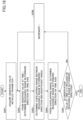
- FIG. 18 is a flowchart that shows the monitoring process according to embodiment 2 of the present disclosure. This monitoring process is performed by the monitoring device 100 described above, and can be realized, for example, by one or more processors that execute programs stored in one or more memories of the monitoring device 100.
- step S202 the determining part 120 determines a forward-direction reachable range F1 i that can be reached from the observed value w i at time i in the forward direction on the time axis.
- the forward-direction reachable range F i of above-described embodiment 1 is a range that can be reached between the observed value w i and time (i+1)
- the forward-direction reachable range F1 i according to embodiment 2 is a range that can be reached between the observed value w i at time i and a time n.
- the determining part 120 may determine the forward-direction reachable range F1 i based on the observed value w i at time i and the variation range.
- step S203 the determining part 120 determines the overlapping range O i between the forward-direction reachable range F1 i and the insufficient range N according to the specification ⁇ .
- step S204 the determining part 120 determines a reachable range F2 i that can be reached from the overlapping range O i in the forward direction on the time axis.
- step S205 the determining part 120 determines whether the observed value w i+1 at time (i+1) is included in the reachable range F2 i . That is, the determining part 120 determines whether it is possible to reach the observed value w i+1 from the observed value w i , via the insufficient range N, by determining whether it is possible to reach the observed value w i+1 after the observed value w i enters the insufficient range N.
- the determining part 120 determines that there is a possibility that the parameter value is in the insufficient range N between the observed values w i and w i+1 , and determines that the cyber-physical model M does not satisfy the specification ⁇ , thereupon ending the monitoring process.
- the determining part 120 determines that there is no possibility that the parameter value is in the insufficient range N between the observed values w i and w i+1 , increments the parameter i in step S206, and repeats steps S202 to S205 described above.
- a monitoring process is performed to determine whether or not a constant temperature bath control system that controls a constant temperature bath by turning on/off a heater satisfies a specification ⁇ : "the temperature T is in the range of 70 to 80 degrees (70 ⁇ T ⁇ 80)."
- the temperature T rises in the range of 2 to 4 degrees per unit time when the heater is turned on (ON), and drops in the range of 0 to 2 degrees per unit time when the heater is turned off (OFF). That is, as described in embodiment 1, such a constant temperature bath control system can be represented by a hybrid automaton that can express discrete mode changes of a differential equation.
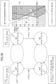
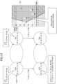
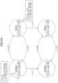
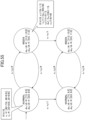
- the hybrid automaton of FIG. 6 is enhanced to hybrid automata including transition to the insufficient range "T ⁇ 70 or T>80," as shown in FIG. 19 .
- the upper half of the enhanced hybrid automata represents transition between the heater-off state and the heater-on state within a range the specification ⁇ is satisfied, from the initial state (start).
- the lower-half hybrid automaton is a duplicate of the upper-half hybrid automaton, and represents transition between the heater-off state and the heater-on state, after transition from the heater-off state and the heater-on state in the range in which the specification ⁇ is satisfied in the upper-half hybrid automaton, to an insufficient range.
- the determining part 120 sets the off state of the upper-half hybrid automaton to the initial state, as shown in FIG. 20 .
- the determining part 120 determines a forward-direction reachable range F1OFF 1 of the temperature T that can be reached from the observed value T 1 in the forward direction on the time axis while the present state is in the off state of the upper-half hybrid automaton.
- the temperature T can vary in the range of T ⁇ [75-2t, 75], and, as shown in FIG. 21 , the forward-direction reachable range F1OFF 1 is in a triangular range starting from the observed value T 1 .
- the determining part 120 determines a forward-direction reachable range F1ON 1 of the temperature T that can be reached from the forward-direction reachable range F1OFF 1 in the forward direction on the time axis while the present state is in the on state of the upper-half hybrid automaton.
- the temperature T can vary in the range of T ⁇ [75-2t 1 +2(t-t 1 ), 75+4(t-t 1 )], and, as shown in FIG. 23 , the forward-direction reachable range F1ON 1 is in the triangles that each start from a point in the forward-direction reachable range F1OFF 1 .
- the determining part 120 obtains a forward-direction reachable range F1 1 , as shown in FIG. 24 . Then the determining part 120 removes t 1 , and the temperature T is in the range of T ⁇ [75-2 t , 75+4 t ].
- the determining part 120 transitions the present state to the off state of the upper-half hybrid automaton, as shown in FIG. 25 .
- the temperature T is in the range of T ⁇ [75-2t 2 , 75+4t 2 ].
- the determining part 120 determines triangles that each start from a point in the forward-direction reachable range F1 1 , and confirms that these triangles are included in the forward-direction reachable range F1 1 . Then, the determining part 120 removes t 2 , and, as shown in FIG. 26 , the temperature T is in the range of T ⁇ [75-2 t , 75 + 4t] .
- the determining part 120 transitions the present state from the off state of the upper-half hybrid automaton to the off state of the lower-half hybrid automaton.
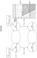
- the overlapping range O 1 is the common range I 1 between the forward-direction reachable range F 1 and the insufficient range N.
- the determining part 120 determines a reachable range F2OFF 1 that can be reached from the overlapping range O 1 in the forward direction on the time axis while the present state is in the off state of the lower-half hybrid automaton.
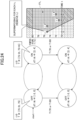
- the determining part 120 determines the ranges of triangles that can be reached from each point of the overlapping range O 1 in the forward direction on the time axis, and, by superimposing the ranges of these triangles over one another, obtains the reachable range F2OFF 1 , as shown in FIG. 28 .
- the determining part 120 transitions the present state to the on state of the lower-half hybrid automaton, and determines a reachable range F2ON 1 that can be reached from the overlapping range O 1 in the forward direction on the time axis while the present state is in the on state of the lower-half hybrid automaton.
- the reachable range F2OFF 1 and the reachable range F2ON2 1 are the same, and so these will be referred to as a "reachable range F2 1 .”
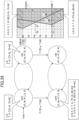
- T ⁇ [79-2t, 67+4t] holds, and, as shown in FIG. 32 , the determining part 120 determines a forward-direction reachable range F1 2 that can be reached in the forward direction on the time axis while the present state is in the off state or the on state of the upper-half hybrid automaton.
- the determining part 120 determines an overlapping range O 2 between the forward-direction reachable range F1 2 and the insufficient range N, and determines a reachable range F2 2 that can be reached from the overlapping range O 2 in the forward direction on the time axis while the present state is in the off state and the on state of the lower-half hybrid automaton.
- the reachable range F2 2 is, for example, the range shown in FIG. 33 .
- the above process is repeated with respect to the observed value T 3 .
- T ⁇ [79-2t, 55+4t] holds, and, as shown in FIG. 36 , the determining part 120 determines a forward-direction reachable range F1 3 that can be reached in the forward direction on the time axis while the present state is in the off state or the on state of the upper-half hybrid automaton.
- the determining part 120 determines an overlapping range O 3 between the forward-direction reachable range F1 3 and the insufficient range N, and determines a reachable range F2 3 that can be reached from the overlapping range O 3 in the forward direction on the time axis while the present state is in the off state and the on state of the lower-half hybrid automaton.
- the reachable range F2 3 is, for example, the range shown in FIG. 37 .
- the determining part 120 determines that the constant temperature bath control system does not satisfy the specification ⁇ , as in the monitoring process of embodiment 1.
- the forward-direction reachable range F1 i is a range that can be reached from time i until any point in time, in the forward direction on the time axis.
- the present disclosure is by no means limited to this, and the forward-direction reachable range F1 i may be, for example, a range that can be reached from time i until time (i+1) in the forward direction.
- a monitoring process is performed to determine whether or not an automobile control system that controls an automobile satisfies a specification ⁇ : "the velocity v is always 120 km/h or slower (v ⁇ 120)."
- the automobile control system operates an automobile in a low-speed mode (LOW) and a high-speed mode (HIGH). A minimum interval of 2 seconds is required to switch the mode.
- the velocity v is from 0 to 90 km/h (v ⁇ [0, 90])
- the velocity v varies in a range of -6 to 15 km/h per unit time (dv/dt ⁇ [-6, 15]).
- the velocity v is 30 km/h or faster (v ⁇ 30), and, in the high-speed mode, the velocity v varies in a range of -6 to 7 km/h per unit time (dv/dt ⁇ [-6, 7]). Also, transition from the low-speed mode to the high-speed mode is possible only when v ⁇ 45 holds, and transition from the high-speed mode to the low-speed mode is possible only when v ⁇ 50 holds. Also, the time to spend in each mode is represented by a parameter c.
- the hybrid automaton of FIG. 15 is enhanced to hybrid automata including transition to the insufficient range N "v>120," as shown in FIG. 39 .
- the upper half of the enhanced hybrid automata represents transition between the low-speed mode and the high-speed mode of the automobile within a range the specification ⁇ is satisfied, from the initial state (start).
- the lower-half hybrid automaton is a duplicate of the upper-half hybrid automaton, and represents transition between the low-speed mode and the high-speed mode of the automobile, after transition from the low-speed mode and the high-speed mode in the range in which the specification ⁇ is satisfied in the upper-half hybrid automaton, to an insufficient range.
- the range that can be reached from the lower-half hybrid automaton corresponds to a range that can be reached after the behavior demonstrated by the upper-half hybrid automaton enters a dangerous range while in progress.
- the monitoring process was explained by calculating various ranges and showing their inclusion relations in a graphic manner.
- the control system being subject to monitoring may not be always as simple as it can be illustrated.
- a monitoring process to use hybrid automata will be described without illustrating their inclusion relations in a graphic manner.
- the conditional expressions of the illustrated hybrid automata can be calculated based on differential equations, configuration conditions, and the like, and may be calculated by using any known library for polyhedral calculation such as Parma Polyhedra Library (PPL) (for more details, see, for example, https://www.bugseng.com/parma-polyhedra-librar) .
- PPL Parma Polyhedra Library
- the determining part 120 derives t ⁇ [3, 6], v ⁇ [45, 90], and v ⁇ 15t+15, from the low-speed mode prior to the shift and the conditions for the transition v ⁇ 45 and c ⁇ 2. Also, the timer parameter c is reset to zero.
- the determining part 120 can derive the reachable range v+8c ⁇ 15t+15, 3 ⁇ c+3 ⁇ t ⁇ 6, 30 ⁇ v, and v ⁇ [45-6c, 90+7c].
- the determining part 120 derives t ⁇ [6, 15], v ⁇ [45, 90], and 90-6(t-6) ⁇ v from the low-speed mode prior to the shift and the conditions for the transition v ⁇ 45 and c ⁇ 2. Also, the timer parameter c is reset to zero.
- the determining part 120 assumes that the present state has shifted from the high-speed mode of the upper-half hybrid automaton to the lower-half hybrid automaton for the insufficient range, and duplicates the conditions for the upper-half hybrid automaton's high-speed mode, as conditions for the lower-half hybrid automaton.
- v ⁇ 120 is added.
- the determining part 120 can determine that the derived range can reach the insufficient range N "v>120," and determine that the automobile control system does not satisfy the specification ⁇ .
- the observed values in the above-described embodiments are one-dimensional values such as temperature and velocity
- the observed values according to the present disclosure are by no means limited to these, and vector values of two or more dimensions, such as the pair of temperature and humidity, the respective positions of N automobiles, and so forth may be used as well.
- a process of monitoring the inter-vehicle distance between two platooning automobiles may be considered.
- the vehicle control system for platooning automobiles satisfies the specification that the inter-vehicle distance x 1 -x 2 (where x i is the position of an automobile i) is always greater than or equal to 1, monitoring is performed based on observation vectors of each automobile's running position, sampled every 10 seconds.
- the automobile control system maintains a distance between two automobiles by switching between a normal mode (NORMAL) and an inter-vehicle distance securing mode (WIDEN). Switching to the inter-vehicle distance securing mode is possible only when x 1 -x 2 ⁇ 4 holds, and switching to the normal mode is possible only when x 1 -x 2 ⁇ 4 holds.
- the velocity in the normal mode is dx 1 /dt ⁇ [7.5, 8.5] and dx 2 /dt ⁇ [8.0, 9.0], and the velocity in the inter-vehicle distance securing mode is dx 1 /dt ⁇ [11.0, 13.0] and dx 2 /dt ⁇ [9.0, 11.0].
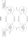
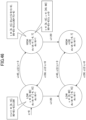
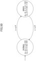
- the hybrid automaton can be described by the state transition diagram shown in FIG. 50 .
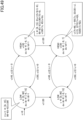
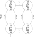
- the hybrid automaton shown in FIG. 50 is enhanced to include a hybrid automaton related to the insufficient range, as shown in FIG. 51 .
- the range of observation vectors that can be reached in the forward direction by a second point in time is x 1 ⁇ [40+7.5t, 40+8.5t] and x 2 ⁇ [25+8.0t, 25+9.0t], as shown in FIG. 53 .
- the determining part 120 derives 0 ⁇ t ⁇ 10, x 1 -x 2 ⁇ 4, x 1 ⁇ [40+7.5t, 40+8.5t], and x 2 ⁇ [25+8.0t, 25+9.Ot], from the normal mode prior to the shift and the conditions for the transition.
- the determining part 120 can derive, as shown in FIG. 55 , a reachable range 0 ⁇ t ⁇ 10, x 1 ⁇ 13t-1/3, -x 1 +11/3x 2 -20t ⁇ 92, x 2 ⁇ 11t+31/3, 4x 1 -7x 2 +33t ⁇ -15, and x 1 ⁇ 7.5t+40.
- the determining part 120 determines whether the specification: "x 1 -x 2 is always greater than or equal to 1" is satisfied, from the reachable ranges for the normal mode and inter-vehicle distance securing mode derived as described above. If the specification is satisfied, the determining part 120 similarly derives the reachable ranges for the observation vectors at the second point in time, and determines whether the specification is satisfied. On the other hand, if the specification is not satisfied, the determining part 120 determines that the automobile control system does not satisfy the specification.
- linear hybrid automata the differentiation of each observed value is given in the form of a 1 dx 1 /dt+ ... +a n dx n /dt ⁇ c.
- a hybrid automaton is beyond the range of a linear hybrid automaton, it is not possible to calculate exact reachable ranges.
- there may be a hybrid automaton including a differential equation such as dx/dt 1/x.
- dx/dt -0.01x+0.005y+2, x ⁇ [0, 100], and y ⁇ [0, 100] and so forth do not constitute a linear hybrid automaton that can be expressed in the form of a 1 dx 1 /dt+ ... +a n dx n /dt ⁇ c, and it is therefore not possible to analyze, in a strict manner, where a hybrid automaton containing a differential equation like this can reach.
- the specification may relate to the passage of time.
- the specification is fixed regardless of time, but the present disclosure is also applicable to specifications that depend on the passage of time.
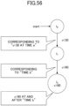
- an automobile control system may employ a specification ⁇ : "It is not good to satisfy v ⁇ 30 at a certain point time a, and then always satisfy v>90 from a certain point in time b onward.”
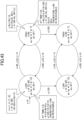
- This specification ⁇ can be expressed, for example, by the hybrid automaton shown in FIG. 56 .
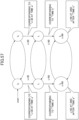
- hybrid automata incorporating the specification ⁇ can be expressed by the state transition diagram shown in FIG. 57 .
Landscapes
- Engineering & Computer Science (AREA)
- Physics & Mathematics (AREA)
- General Physics & Mathematics (AREA)
- Theoretical Computer Science (AREA)
- Automation & Control Theory (AREA)
- Quality & Reliability (AREA)
- General Engineering & Computer Science (AREA)
- Health & Medical Sciences (AREA)
- Biomedical Technology (AREA)
- General Health & Medical Sciences (AREA)
- Computing Systems (AREA)
- Testing And Monitoring For Control Systems (AREA)
Abstract
Description
- The present disclosure relates to a monitoring device and a monitoring method.
- When inspecting the operation of a control system such as a cyber-physical model, parameters that relate to the operation of the control system are discretely sampled and monitored. When parameters are monitored based on discrete sampling, it is necessary to estimate and interpolate the changes with the parameters that occur between samplings as accurately as possible. Especially, in IoT (Internet of Things), the sampling interval is sometimes extended for reduced power consumption. However, accurate inspection of operation can be performed only by accurately monitoring the unsafe phenomena that occur between samplings.
- Conventionally, linear interpolation and constant interpolation are used for parameter interpolation between samplings. In linear interpolation, sampling points are interpolated based on a linear formula, as shown in
FIG. 1(a) . In constant interpolation, sampling points are interpolated based on a constant, as shown inFIG. 1(b) . - However, the actual variation of a parameter between samplings might be as shown in
FIG. 1(c) , and conventional linear interpolation and constant interpolation cannot monitor such unsafe phenomena of the control system accurately. - In view of the above problem, the present disclosure aims to provide a technique for monitoring the behavior of a control system accurately.
- In order to solve the above problem, one aspect of the present invention relates to a monitoring device that has: an acquiring part configured to acquire observed values of a variable that is sampled with respect to a behavior of a control system while the control system is running; and a determining part configured to determine a range of possible observed values that the variable possibly reaches upon a temporal change thereof, based on the acquired observed values, and determine whether a variation range of the acquired observed values satisfies a specification, based on an overlap between the range of the possible observed values and a range not satisfying the specification.
- According to the present disclosure, it is possible to provide a technique for monitoring the behavior of a control system accurately.
-
- [
FIG. 1] FIG. 1 is an overview that shows a specific example of a sampling method; - [
FIG. 2] FIG. 2 is an overview that shows a monitoring device according to one embodiment of the present disclosure; - [
FIG. 3] FIG. 3 is a block diagram that shows a hardware structure of a monitoring device according to one embodiment of the present disclosure; - [
FIG. 4] FIG. 4 is a block diagram that shows a functional structure of a monitoring device according to one embodiment of the present disclosure; - [
FIG. 5] FIG. 5 is a flowchart that shows a monitoring process according to anembodiment 1 of the present disclosure; - [
FIG. 6] FIG. 6 is a state transition diagram that shows a hybrid automaton according to one embodiment of the present disclosure; - [
FIG. 7] FIG. 7 is a diagram that shows observed values according to one embodiment of the present disclosure; - [
FIG. 8] FIG. 8 is a diagram that shows a monitoring process according to one embodiment of the present disclosure; - [
FIG. 9] FIG. 9 is a diagram that shows a monitoring process according to one embodiment of the present disclosure; - [
FIG. 10] FIG. 10 is a diagram that shows a monitoring process according to one embodiment of the present disclosure; - [
FIG. 11] FIG. 11 is a diagram that shows a monitoring process according to one embodiment of the present disclosure; - [
FIG. 12] FIG. 12 is a diagram that shows a monitoring process according to one embodiment of the present disclosure; - [
FIG. 13] FIG. 13 is a diagram that shows a monitoring process according to one embodiment of the present disclosure; - [
FIG. 14] FIG. 14 is a diagram that shows a monitoring process according to one embodiment of the present disclosure; - [
FIG. 15] FIG. 15 is a state transition diagram that shows a hybrid automaton according to one embodiment of the present disclosure; - [
FIG. 16] FIG. 16 is a diagram that shows observed values according to one embodiment of the present disclosure; - [
FIG. 17] FIG. 17 is a diagram that shows a monitoring process according to one embodiment of the present disclosure; - [
FIG. 18] FIG. 18 is a diagram that shows a monitoring process according to anembodiment 2 of the present disclosure; - [
FIG. 19] FIG. 19 is a state transition diagram that shows a hybrid automaton according to one embodiment of the present disclosure; - [
FIG. 20] FIG. 20 is a diagram that shows a monitoring process according to one embodiment of the present disclosure; - [
FIG. 21] FIG. 21 is a diagram that shows a monitoring process according to one embodiment of the present disclosure; - [
FIG. 22] FIG. 22 is a diagram that shows a monitoring process according to one embodiment of the present disclosure; - [
FIG. 23] FIG. 23 is a diagram that shows a monitoring process according to one embodiment of the present disclosure; - [
FIG. 24] FIG. 24 is a diagram that shows a monitoring process according to one embodiment of the present disclosure; - [
FIG. 25] FIG. 25 is a diagram that shows a monitoring process according to one embodiment of the present disclosure; - [
FIG. 26] FIG. 26 is a diagram that shows a monitoring process according to one embodiment of the present disclosure; - [
FIG. 27] FIG. 27 is a diagram that shows a monitoring process according to one embodiment of the present disclosure; - [
FIG. 28] FIG. 28 is a diagram that shows a monitoring process according to one embodiment of the present disclosure; - [
FIG. 29] FIG. 29 is a diagram that shows a monitoring process according to one embodiment of the present disclosure; - [
FIG. 30] FIG. 30 is a diagram that shows a monitoring process according to one embodiment of the present disclosure; - [
FIG. 31] FIG. 31 is a diagram that shows a monitoring process according to one embodiment of the present disclosure; - [
FIG. 32] FIG. 32 is a diagram that shows a monitoring process according to one embodiment of the present disclosure; - [
FIG. 33] FIG. 33 is a diagram that shows a monitoring process according to one embodiment of the present disclosure; - [
FIG. 34] FIG. 34 is a diagram that shows a monitoring process according to one embodiment of the present disclosure; - [
FIG. 35] FIG. 35 is a diagram that shows a monitoring process according to one embodiment of the present disclosure; - [
FIG. 36] FIG. 36 is a diagram that shows a monitoring process according to one embodiment of the present disclosure; - [
FIG. 37] FIG. 37 is a diagram that shows a monitoring process according to one embodiment of the present disclosure; - [
FIG. 38] FIG. 38 is a diagram that shows a monitoring process according to one embodiment of the present disclosure; - [
FIG. 39] FIG. 39 is a diagram that shows a monitoring process according to one embodiment of the present disclosure; - [
FIG. 40] FIG. 40 is a diagram that shows a monitoring process according to one embodiment of the present disclosure; - [
FIG. 41] FIG. 41 is a diagram that shows a monitoring process according to one embodiment of the present disclosure; - [
FIG. 42] FIG. 42 is a diagram that shows a monitoring process according to one embodiment of the present disclosure; - [
FIG. 43] FIG. 43 is a diagram that shows a monitoring process according to one embodiment of the present disclosure; - [
FIG. 44] FIG. 44 is a diagram that shows a monitoring process according to one embodiment of the present disclosure; - [
FIG. 45] FIG. 45 is a diagram that shows a monitoring process according to one embodiment of the present disclosure; - [
FIG. 46] FIG. 46 is a diagram that shows a monitoring process according to one embodiment of the present disclosure; - [
FIG. 47] FIG. 47 is a diagram that shows a monitoring process according to one embodiment of the present disclosure; - [
FIG. 48] FIG. 48 is a diagram that shows a monitoring process according to one embodiment of the present disclosure; - [
FIG. 49] FIG. 49 is a diagram that shows a monitoring process according to one embodiment of the present disclosure; - [
FIG. 50] FIG. 50 is a state transition diagram that shows a hybrid automaton according to a modification of the present disclosure; - [
FIG. 51] FIG. 51 is a state transition diagram that shows a hybrid automaton according to a modification of the present disclosure; - [
FIG. 52] FIG. 52 is a diagram that shows a monitoring process according to a modification of the present disclosure; - [
FIG. 53] FIG. 53 is a diagram that shows a monitoring process according to a modification of the present disclosure; - [
FIG. 54] FIG. 54 is a diagram that shows a monitoring process according to a modification of the present disclosure; - [
FIG. 55] FIG. 55 is a diagram that shows a monitoring process according to a modification of the present disclosure; - [
FIG. 56] FIG. 56 is a state transition diagram that shows a hybrid automaton according to a modification of the present disclosure; and - [
FIG. 57] FIG. 57 is a state transition diagram that shows a hybrid automaton according to a modification of the present disclosure. - In the following embodiment, a monitoring device for a control system such as a cyber-physical model will be disclosed.
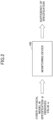
- When a
monitoring device 100 according to one embodiment of the present disclosure acquires a cyber-physical model M, a specification ϕ, and an observed value w of the cyber-physical model M, as shown inFIG. 2 , themonitoring device 100 determines whether or not the cyber-physical model M satisfies the specification ϕ. The cyber-physical model M generally refers to a system that is built by combining a physical system such as an automobile, a robot, and a building, with an information system such as a computer. - In the following embodiment, the cyber-physical model M operates in discrete modes such as on mode and off mode, low-speed mode and high-speed mode, and so forth. As a result of such operation, for example, parameter values such as the velocity of an automobile, the amount of products a robot produces, the air-conditioning temperature in a building, and so forth vary. Such variation may be defined by, for example, conditions that express changes of parameter values over time, such as differential equations defined in advance for each discrete mode. Also, the specification ϕ may be, for example, "v<vo" for velocity "v," "po<p" for the amount of product production per hour "p," "tmpL<tmp<tmpH" for the room temperature "tmp," and so forth.
- While these parameter values vary substantially continuously, the observed values w of a parameter are sampling values collected on a discrete basis, such as at a predetermined sampling rate. Therefore, as mentioned earlier, observed values w cannot always explain the actual variation of parameter values between samplings, and it is not possible to determine whether the cyber-physical model M satisfies a specification ϕ based on observed values w.
- While there are such limitations to sampling, the
monitoring device 100 collects observed values w regarding a behavior of the cyber-physical model M, determines a possible variation range of a parameter value based on the collected observed values w, and determines whether the cyber-physical model M satisfies the specification ϕ based on the observed values w and the variation range. - Here, as shown in
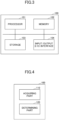
FIG. 3 , for example, themonitoring device 100 may have a hardware structure including aprocessor 101 such as a central processing unit (CPU), a random access memory (RAM), amemory 102 such as a flash memory, astorage 103, and an input/output (I/O)interface 104. - The
processor 101 executes various processes of themonitoring device 100, which will be described later. - The
memory 102 stores various data and programs in themonitoring device 100, and, in particular, functions as a working memory for working data, running programs, and so forth. To be more specific, thememory 102 stores the programs that are loaded from thestorage 103 to execute and control various processes, which will be described later, and functions as a working memory while theprocessor 101 executes these programs. - The
storage 103 stores various data and programs in themonitoring device 100. - The I/
O interface 104 is an interface for receiving commands, input data, and so forth from the user, playing/displaying the output results, and inputting/outputting data to and from external devices. For example, the I/O interface 104 may be a device for inputting/outputting various data, such as a universal serial bus (USB), a communication line, a keyboard, a mouse, a display, a microphone, a speaker, and the like. - However, the
monitoring device 100 according to the present disclosure is by no means limited to the hardware structure described above, and may have any other suitable hardware structure. For example, one or more of various processes performed by themonitoring device 100 may be implemented by processing circuitry or electronic circuitry that is hardwired to accomplish these. - Next, the
monitoring device 100 according to one embodiment of the present disclosure will be described with reference toFIG. 4. FIG. 4 is a block diagram that shows a functional structure of themonitoring device 100 according to one embodiment of the present disclosure. - As shown in
FIG. 4 , themonitoring device 100 has an acquiringpart 110 and a determiningpart 120. The acquiringpart 110 and determiningpart 120 are installed in themonitoring device 100, and implemented by one or more processors that execute one or more programs stored in one or more memories. - The acquiring
part 110 acquires observed values sampled with respect to a behavior of the control system. To be more specific, the acquiringpart 110 acquires the parameter values that are collected on a discrete basis during the operation of the cyber-physical model M, as observed values w. - For example, assuming that the cyber-physical model M is an automobile control system, the velocity, the engine speed, the number of gears, and so forth may be treated as parameter values. Also, if the cyber-physical model M is a robot control system, the amount of product production, the power consumption, and so forth may be treated as parameter values. Furthermore, if the cyber-physical model M is a building control system, the room temperature, the brightness of lighting, the power consumption, and so forth may be treated as parameter values. The observed values w may be, for example, a sequence of parameter values collected at a predetermined sampling rate. In the event the velocity is collected every x seconds while the cyber-physical model M is running and treated as observed values w, the observed values w can be expressed as: w= (w1, w2, ..., wn). Here, wi represents the velocity at a time i. The acquiring
part 110 provides the acquired observed values w to the determiningpart 120. - The determining
part 120 determines the variation range of the observed values with respect to a behavior of the control system, and determines whether the variation range of observed values satisfies the specification regarding observed values. To be more specific, upon acquiring observed values w, the determiningpart 120 determines the range of variation of the observed values w that can be reached from each observed value wi, with respect to the behavior of the cyber-physical model M, by using a mathematical model, and determines whether the determined variation range satisfies the specification ϕ. Here, although a mathematical model using the behavior of the cyber-physical model M can be built if the exact behavior of the cyber-physical model M is known, if the exact behavior of the cyber-physical model M is not clear, a mathematical model can be used to determine an approximate operating range that covers the actual behavior of the cyber-physical model M. If the variation range does not satisfy the specification ϕ, the determiningpart 120 determines that the cyber-physical model M does not satisfy the specification ϕ. If the range of variation that can be reached from each observed value wi satisfies the specification ϕ, the determiningpart 120 determines that the cyber-physical model M satisfies the specification ϕ. - In one embodiment, the determining
part 120 may determine a first reachable range that can be reached in the forward direction, between the observed value at time i and a time (i+1), and a second reachable range that can be reached in the backward direction, between the observed value at time (i+1) and time i, and determine whether the variation ranges satisfy the specification based on whether there is an overlapping range between a common range between the first reachable range and the second reachable range, and a range not satisfying the specification (also referred to as an "insufficient range"). To be more specific, for the observed value at each time i, the determiningpart 120 determines a reachable range Fi that can be reached in the forward direction, between the observed value at time i and time (i+1), and a reachable range Bi that can be reached in the backward direction, between the observed value at time (i+1) and time i, and determines whether the common range Ii between the reachable ranges Fi and Bi overlap the specification's insufficient range N. When a common range Ii that overlaps the insufficient range N is detected, the determiningpart 120 determines that the cyber-physical model M does not satisfy the specification ϕ. If the common range Ii and the specification's insufficient range N do not overlap with respect to any of times i, the determiningpart 120 determines that the cyber-physical model M satisfies the specification ϕ. -
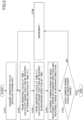
FIG. 5 is a flowchart that shows the monitoring process according toembodiment 1 of the present disclosure. This monitoring process is performed by themonitoring device 100 described above, and can be realized, for example, by one or more processors that execute programs stored in one or more memories of themonitoring device 100. - As shown in
FIG. 5 , in step S101, the acquiringpart 110 acquires observed values w=(w1, w2, ..., wn) for the cyber-physical model M, and initializes a parameter i as: i=1. - In step S102, the determining
part 120 determines a forward-direction reachable range Fi that can be reached in the forward direction on the time axis, between the observed value wi at time i and time (i+1). For example, if the variation range of observed values per unit time is made clear in advance from a differential equation that determines the variation of a parameter value over time, the determiningpart 120 may determine the forward-direction reachable range Fi based on the observed value wi at time i and the variation range. - In step S103, the determining
part 120 determines a backward-direction reachable range Bi that can be reached in the backward direction, between the observed value wi+1 at time (i+1) and time i. For example, if a differential equation that defines the changes of a parameter value over time makes clear, in advance, the variation range of observed values per unit time, the determiningpart 120 may determine the backward-direction reachable range Bi based on the observed value wi+1 at time (i+1) and the variation range. - In step S104, the determining
part 120 determines the common range Ii between the forward-direction reachable range Fi and the backward-direction reachable range Bi. The common range Ii is a range in which the forward-direction reachable range Fi and the backward-direction reachable range Bi overlap. - In step S105, the determining
part 120 determines whether the common range Ii overlaps the insufficient range N according to the specification ϕ. If the common range Ii and the insufficient range N overlap (S105: YES), the determiningpart 120 determines that the cyber-physical model M does not satisfy the specification ϕ, and ends the process. On the other hand, if the common range Ii and the insufficient range N do not overlap (S105: NO), the determiningpart 120 increments the parameter i in step S106, and repeats steps S102 to S105. - To illustrate an example, a case will be described below in which a monitoring process is performed to determine whether or not a constant temperature bath control system that controls a constant temperature bath by turning on/off a heater satisfies a specification ϕ: "the temperature T is in the range of 70 to 80 degrees (70≤T≤80)." In the constant temperature bath control system according to the present embodiment, the temperature T rises in the range of 2 to 4 degrees per unit time when the heater is turned on (ON), and drops in the range of 0 to 2 degrees per unit time when the heater is turned off (OFF). For example, as shown in
FIG. 6 , such a constant temperature bath control system can be represented by a hybrid automaton that can express discrete mode changes of a differential equation. At this time, assume that, as illustrated inFIG. 7 , the acquiringpart 110 acquires four observed values, namely T1=75 (t=0), T2=75 (t=2), T3=71 (t=4), and T4=72 (t=6), sampled every 2 seconds with respect to a constant temperature bath that is controlled by the constant temperature bath control system. - First, for the first point in time (i=1), the determining
part 120 derives a reachable range F1 that can be reached in the forward direction on the time axis, between the observed value T1 at the first point in time and a second point in time. Since the starting point is T1=75, it is possible to determine that the temperature T is in the variation range of 83 to 71 degrees until the second point in time, which is 2 seconds later, and the determiningpart 120 determines the reachable range F1 of a triangular shape, as shown inFIG. 8 . - On the other hand, the determining
part 120 also derives a reachable range B1 that can be reached in the backward direction on the time axis, between an observed value T2 at the second point in time and the first point in time. Since the starting point is T2=75, it is possible to determine that the temperature T is in the variation range of 67 to 79 degrees until the first point in time, which is 2 seconds earlier, and the determiningpart 120 determines the reachable range B1 of a triangular shape, as shown inFIG. 9 . - Then, the determining
part 120 derives the common range I1 between the reachable range F1 and the reachable range B1 with respect to the first point in time. For example, the shaded part inFIG. 10 may be derived as the common range I1. The determiningpart 120 determines whether there is an overlapping range between the common range I1 and the insufficient range N according to the specification ϕ: "T<70 degrees or 80 degrees<T." As understood from the positional relationship between the common range I1 and the insufficient range N shown inFIG. 10 , there is no overlapping range between the common range I1 and the insufficient range N, and therefore the determiningpart 120 determines that the variation range of the temperature T from the first point in time to the second point in time satisfies the specification ϕ. - Next, for the second point in time (i=2), the determining
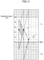
part 120 likewise derives a reachable range F2 that can be reached in the forward direction on the time axis, between an observed value T2 at the second point in time and a third point in time, and a reachable range B2 that can be reached in the backward direction on the time axis, between an observed value T3 at the third point in time and the second point in time. The reachable range F2 and the reachable range B2 are triangular ranges, as shown inFIG. 11 . - Then, the determining
part 120 derives a common range I2 between the reachable range F2 and the reachable range B2 with respect to the second point in time. For example, the shaded part inFIG. 12 where two triangles contact one another may be derived as the common range I2. As understood from the positional relationship between the common range I2 and the insufficient range N shown inFIG. 12 , there is no overlapping range between the common range I2 and the insufficient range N, and therefore the determiningpart 120 determines that the variation range of the temperature T from the second point in time to the third point in time satisfies the specification ϕ. - Next, for the third point in time (i=3), the determining
part 120 likewise derives a reachable range F3 that can be reached in the forward direction on the time axis, between an observed value T3 at the third point in time and a fourth point in time, and a reachable range B3 that can be reached in the backward direction on the time axis, between an observed value T4 of the fourth point in time and the third point in time. The reachable range F3 and the reachable range B3 are triangular ranges, as shown inFIG. 13 . - Then, the determining
part 120 derives a common range I3 between the reachable range F3 and the reachable range B3 with respect to the third point in time. For example, the shaded part inFIG. 14 may be derived as the common range I3. As understood from the positional relationship between the common range I3 and the insufficient range N shown inFIG. 14 , there is an overlapping range between the common range I3 and the insufficient range N, and therefore the determiningpart 120 determines that the variation range of the temperature T from the third point in time to the fourth point in time does not satisfy the specification ϕ, and that the constant temperature bath control system does not satisfy the specification ϕ. - To illustrate another example, a case will be described below in which a monitoring process is performed to determine whether or not an automobile control system that controls an automobile satisfies a specification ϕ: "the velocity v is always 120 km/h or slower (v≤120)." The automobile control system according to the present embodiment operates an automobile in a low-speed mode (LOW) and a high-speed mode (HIGH). A minimum interval of 2 seconds is required to switch the mode. In the low-speed mode, the velocity v is from 0 to 90 km/h (v∈[0, 90]), and, in the low-speed mode, the velocity v varies in a range of -6 to 15 km/h per unit time (dv/dt∈[-6, 15]). On the other hand, in the high-speed mode, the velocity v is 30 km/h or faster (v≥30), and, in the high-speed mode, the velocity v varies in a range of -6 to 7 km/h per unit time (dv/dt∈[-6, 7]). Also, transition from the low-speed mode to the high-speed mode is possible only when v≥45 holds, and transition from the high-speed mode to the low-speed mode is possible only when v≤50 holds. Also, the time to spend in each mode is represented by a parameter c. For example, as shown in
FIG. 15 , the automobile control system according to this embodiment can be represented by a hybrid automaton that can express discrete mode changes of a differential equation. For example, assume that, as illustrated inFIG. 16 , the acquiringpart 110 acquires three observed values, namely v1=30 (t=1), v2=90 (t=6), and v3=100 (t=15), sampled with respect to an automobile that is controlled by the automobile control system. - First, for the first point in time (i=1), the determining
part 120 derives a reachable range F1 that can be reached in the forward direction on the time axis, between an observed value v1 at the first point in time (t=1) and a second point in time (t=6), and a reachable range B1 that can be reached in the backward direction on the time axis, between an observed value v2 at the second point in time and the first point in time, and derives the common range I1 between the reachable range F1 and the reachable range B1 with respect to the first point in time. For example, the shaded part inFIG. 17 may be derived as the common range I1. The determiningpart 120 determines whether there is an overlapping range between the common range I1 and the insufficient range N (v>120) of the specification ϕ. As understood from the positional relationship between the common range I1 and the insufficient range N shown inFIG. 17 , there is no overlapping range between the common range I1 and the insufficient range N, and therefore the determiningpart 120 determines that the variation range of the velocity v from the first point in time to the second point in time satisfies the specification ϕ. - Next, for the second point in time (i=2), the determining
part 120 likewise derives a reachable range F2 that can be reached in the forward direction on the time axis, between an observed value v2 at the second point in time (t=6) and a third point in time (t=15), and a reachable range B2 that can be reached in the backward direction on the time axis, between an observed value v3 at the third point in time and the second point in time, and derives a common range I2 between the reachable range F2 and the reachable range B2 with respect to the second point in time. For example, the shaded part inFIG. 17 may be derived as the common range I2. The determiningpart 120 determines whether there is an overlapping range between the common range I2 and the insufficient range N (v>120) of the specification ϕ. As understood from the positional relationship between the common range I2 and the insufficient range N shown inFIG. 17 , there is an overlapping range between the common range I2 and the insufficient range N, and therefore the determiningpart 120 determines that the variation range of the velocity v from the second point in time to the third point in time does not satisfy the specification ϕ. - In another embodiment, the determining
part 120 may determine a forward-direction reachable range that can be reached from an observed value at time i in the forward direction on the time axis, determine the overlapping range between the forward-direction reachable range and a range not satisfying a specification ϕ, and determine whether a variation range satisfies the specification based on whether or not an observed value at time (i+1) is included in a reachable range that can be reached from the overlapping range in the forward direction on the time axis. To be more specific, given the observed value at each time i, the determiningpart 120 determines a forward-direction reachable range F1i that can be reached in the forward direction on the time axis, between the observed value at time i and an overlapping range Oi between the forward-direction reachable range F1i and the insufficient range N, and determines whether the observed value at time (i+1) is included in a reachable range F2i that can be reached from the overlapping range Oi in the forward direction on the time axis. If the observed value at time (i+1) is included in the reachable range F2i, the determiningpart 120 determines that the cyber-physical model M does not satisfy the specification ϕ. The determiningpart 120 determines that the cyber-physical model M satisfies the specification ϕ if the observed value at time (i+1) is not included in any of the reachable ranges F2i related to all time points i. -
FIG. 18 is a flowchart that shows the monitoring process according toembodiment 2 of the present disclosure. This monitoring process is performed by themonitoring device 100 described above, and can be realized, for example, by one or more processors that execute programs stored in one or more memories of themonitoring device 100. - As shown in
FIG. 18 , in step S201, the acquiringpart 110 acquires observed values w=(w1, w2, ..., wn) for the cyber-physical model M, and initializes a parameter i as: i=1. - In step S202, the determining
part 120 determines a forward-direction reachable range F1i that can be reached from the observed value wi at time i in the forward direction on the time axis. Note that, while the forward-direction reachable range Fi of above-describedembodiment 1 is a range that can be reached between the observed value wi and time (i+1), the forward-direction reachable range F1i according toembodiment 2 is a range that can be reached between the observed value wi at time i and a time n. For example, if the variation range of observed values per unit time is made clear in advance from a differential equation or the like, the determiningpart 120 may determine the forward-direction reachable range F1i based on the observed value wi at time i and the variation range. - In step S203, the determining
part 120 determines the overlapping range Oi between the forward-direction reachable range F1i and the insufficient range N according to the specification ϕ. - In step S204, the determining
part 120 determines a reachable range F2i that can be reached from the overlapping range Oi in the forward direction on the time axis. - In step S205, the determining
part 120 determines whether the observed value wi+1 at time (i+1) is included in the reachable range F2i. That is, the determiningpart 120 determines whether it is possible to reach the observed value wi+1 from the observed value wi, via the insufficient range N, by determining whether it is possible to reach the observed value wi+1 after the observed value wi enters the insufficient range N. - If observed value wi+1 is included in the reachable range F2i (S205: YES), the determining
part 120 determines that there is a possibility that the parameter value is in the insufficient range N between the observed values wi and wi+1, and determines that the cyber-physical model M does not satisfy the specification ϕ, thereupon ending the monitoring process. On the other hand, if the observed value wi+1 is not included in the reachable range F2i (S205: NO), the determiningpart 120 determines that there is no possibility that the parameter value is in the insufficient range N between the observed values wi and wi+1, increments the parameter i in step S206, and repeats steps S202 to S205 described above. - To illustrate an example, a case will be described below in which, as in
embodiment 1, a monitoring process is performed to determine whether or not a constant temperature bath control system that controls a constant temperature bath by turning on/off a heater satisfies a specification ϕ: "the temperature T is in the range of 70 to 80 degrees (70≤T≤80)." In the constant temperature bath control system according to the present embodiment, the temperature T rises in the range of 2 to 4 degrees per unit time when the heater is turned on (ON), and drops in the range of 0 to 2 degrees per unit time when the heater is turned off (OFF). That is, as described inembodiment 1, such a constant temperature bath control system can be represented by a hybrid automaton that can express discrete mode changes of a differential equation. As inembodiment 1, assume that, as illustrated inFIG. 7 , the acquiringpart 110 acquires four observed values, namely T1=75 (t=0), T2=75 (t=2), T3=71 (t=4), and T4=72 (t=6), sampled every 2 seconds with respect to a constant temperature bath that is controlled by the constant temperature bath control system. - According to
embodiment 2, the hybrid automaton ofFIG. 6 is enhanced to hybrid automata including transition to the insufficient range "T<70 or T>80," as shown inFIG. 19 . The upper half of the enhanced hybrid automata represents transition between the heater-off state and the heater-on state within a range the specification ϕ is satisfied, from the initial state (start). The lower-half hybrid automaton is a duplicate of the upper-half hybrid automaton, and represents transition between the heater-off state and the heater-on state, after transition from the heater-off state and the heater-on state in the range in which the specification ϕ is satisfied in the upper-half hybrid automaton, to an insufficient range. - First, for an observed value T1, at time t=0, the determining
part 120 sets the off state of the upper-half hybrid automaton to the initial state, as shown inFIG. 20 . - Next, at time t>0, the determining
part 120 determines a forward-direction reachable range F1OFF1 of the temperature T that can be reached from the observed value T1 in the forward direction on the time axis while the present state is in the off state of the upper-half hybrid automaton. At this time, the temperature T can vary in the range of T∈[75-2t, 75], and, as shown inFIG. 21 , the forward-direction reachable range F1OFF1 is in a triangular range starting from the observed value T1. - Next, at time t=t1 (>0), assume that the determining
part 120 transitions the present state to the ON state of the upper-half hybrid automaton, as shown inFIG. 22 . At this time, the temperature T is in the range of T∈[75-2t, 75]. - Next, at time t>t1, the determining
part 120 determines a forward-direction reachable range F1ON1 of the temperature T that can be reached from the forward-direction reachable range F1OFF1 in the forward direction on the time axis while the present state is in the on state of the upper-half hybrid automaton. At this time, the temperature T can vary in the range of T∈[75-2t1+2(t-t1), 75+4(t-t1)], and, as shown inFIG. 23 , the forward-direction reachable range F1ON1 is in the triangles that each start from a point in the forward-direction reachable range F1OFF1. Then, by superimposing the forward-direction reachable range F1OFF1 and each triangle over one another (that is, F1OFF1+F1ON1), the determiningpart 120 obtains a forward-direction reachable range F11, as shown inFIG. 24 . Then the determiningpart 120 removes t1, and the temperature T is in the range of T∈[75-2t, 75+4t]. - Next, at time t=t2 (>t1), assume that the determining
part 120 transitions the present state to the off state of the upper-half hybrid automaton, as shown inFIG. 25 . At this time, the temperature T is in the range of T∈[75-2t2, 75+4t2]. The determiningpart 120 determines triangles that each start from a point in the forward-direction reachable range F11, and confirms that these triangles are included in the forward-direction reachable range F11. Then, the determiningpart 120 removes t2, and, as shown inFIG. 26 , the temperature T is in the range of T∈[75-2t, 75 + 4t] . - Then, to determine the overlapping range O1 between the forward-direction reachable range F11 and the insufficient range N according to the specification ϕ: "T<70 or T>80," the determining
part 120 transitions the present state from the off state of the upper-half hybrid automaton to the off state of the lower-half hybrid automaton. As shown inFIG. 27 , the overlapping range O1 is the common range I1 between the forward-direction reachable range F1 and the insufficient range N. - Next, the determining
part 120 determines a reachable range F2OFF1 that can be reached from the overlapping range O1 in the forward direction on the time axis while the present state is in the off state of the lower-half hybrid automaton. To be more specific, similar to the above-described method of calculating the forward-direction reachable range F11, the determiningpart 120 determines the ranges of triangles that can be reached from each point of the overlapping range O1 in the forward direction on the time axis, and, by superimposing the ranges of these triangles over one another, obtains the reachable range F2OFF1, as shown inFIG. 28 . - Next, the determining
part 120 transitions the present state to the on state of the lower-half hybrid automaton, and determines a reachable range F2ON1 that can be reached from the overlapping range O1 in the forward direction on the time axis while the present state is in the on state of the lower-half hybrid automaton. As shown inFIG. 29 , the reachable range F2OFF1 and the reachable range F2ON21 are the same, and so these will be referred to as a "reachable range F21." - Then, the determining
part 120 determines whether T2=75 is included in the reachable range F21. As shown inFIG. 30 , T2=75 is not included in the reachable range F21, and therefore the determiningpart 120 determines that it is not possible to reach T2=75 from T1=75 via the insufficient range N, and that the constant temperature bath control system satisfies the specification ϕ in the range oftime 0≤t≤2. - Note that the determining
part 120 may confirm if it is possible to reach from T1 to T2 in the forward direction on the time axis. As shown inFIG. 31 , since the forward-direction reachable range F21, which starts from T1, includes T2=75, it is clear that it is possible to reach from T1 to T2 in the forward direction on the time axis. If it is not possible to reach from T1 to T2 in the forward direction on the time axis, it then can be determined that there was a problem with the observation of the observed value T2. - Next, the above process is repeated with respect to the observed value T2. At time t>2, T∈[79-2t, 67+4t] holds, and, as shown in
FIG. 32 , the determiningpart 120 determines a forward-direction reachable range F12 that can be reached in the forward direction on the time axis while the present state is in the off state or the on state of the upper-half hybrid automaton. - Next, the determining
part 120 determines an overlapping range O2 between the forward-direction reachable range F12 and the insufficient range N, and determines a reachable range F22 that can be reached from the overlapping range O2 in the forward direction on the time axis while the present state is in the off state and the on state of the lower-half hybrid automaton. The reachable range F22 is, for example, the range shown inFIG. 33 . - Then, the determining
part 120 determines whether T3=71 is included in the reachable range F22. As shown inFIG. 34 , T3=71 is not included in the reachable range F22, and therefore the determiningpart 120 determines that it is not possible to reach T3=71 from T2=75 via the insufficient range N, and that the constant temperature bath control system satisfies the specification ϕ in the range oftime 2≤t≤4. - Note that the determining
part 120 may confirm if it is possible to reach from T2 to T3 in the forward direction on the time axis. As shown inFIG. 35 , since the forward-direction reachable range F22, which starts from T2, includes T3=71, it is clear that that it is possible to reach from T2 to T3 in the forward direction on the time axis. If it is not possible to reach from T2 to T3 in the forward direction on the time axis, it then can be determined that there was a problem with the observation of the observed value T3. - Next, the above process is repeated with respect to the observed value T3. At time t>4, T∈[79-2t, 55+4t] holds, and, as shown in
FIG. 36 , the determiningpart 120 determines a forward-direction reachable range F13 that can be reached in the forward direction on the time axis while the present state is in the off state or the on state of the upper-half hybrid automaton. - Next, the determining
part 120 determines an overlapping range O3 between the forward-direction reachable range F13 and the insufficient range N, and determines a reachable range F23 that can be reached from the overlapping range O3 in the forward direction on the time axis while the present state is in the off state and the on state of the lower-half hybrid automaton. The reachable range F23 is, for example, the range shown inFIG. 37 . - Then, the determining
part 120 determines whether T4=72 is included in the reachable range F23. As shown inFIG. 38 , T4=72 is included in the reachable range F23, and therefore the determiningpart 120 determines that it is not possible to reach T4=72 from T3=71 via the insufficient range N, and that the constant temperature bath control system does not satisfy the specification ϕ in the range oftime 4≤t≤6. - As a result of this, the determining
part 120 determines that the constant temperature bath control system does not satisfy the specification ϕ, as in the monitoring process ofembodiment 1. - In the above-described embodiment, the forward-direction reachable range F1i is a range that can be reached from time i until any point in time, in the forward direction on the time axis. However, the present disclosure is by no means limited to this, and the forward-direction reachable range F1i may be, for example, a range that can be reached from time i until time (i+1) in the forward direction.
- To illustrate another example, a case will be described below in which, as in
embodiment 1, a monitoring process is performed to determine whether or not an automobile control system that controls an automobile satisfies a specification ϕ: "the velocity v is always 120 km/h or slower (v≤120)." The automobile control system operates an automobile in a low-speed mode (LOW) and a high-speed mode (HIGH). A minimum interval of 2 seconds is required to switch the mode. In the low-speed mode, the velocity v is from 0 to 90 km/h (v∈[0, 90]), and, in the low-speed mode, the velocity v varies in a range of -6 to 15 km/h per unit time (dv/dt∈[-6, 15]). On the other hand, in the high-speed mode, the velocity v is 30 km/h or faster (v≥30), and, in the high-speed mode, the velocity v varies in a range of -6 to 7 km/h per unit time (dv/dt∈[-6, 7]). Also, transition from the low-speed mode to the high-speed mode is possible only when v≥45 holds, and transition from the high-speed mode to the low-speed mode is possible only when v≤50 holds. Also, the time to spend in each mode is represented by a parameter c. For example, as shown inFIG. 15 , the automobile control system according to this embodiment can be represented by a hybrid automaton that can express discrete mode changes of a differential equation. For example, assume that, as illustrated inFIG. 16 , the acquiringpart 110 acquires three observed values, namely v1=30 (t=1), v2=90 (t=6), and v3=100 (t=15), sampled with respect to an automobile that is controlled by the automobile control system. - According to
embodiment 2, the hybrid automaton ofFIG. 15 is enhanced to hybrid automata including transition to the insufficient range N "v>120," as shown inFIG. 39 . The upper half of the enhanced hybrid automata represents transition between the low-speed mode and the high-speed mode of the automobile within a range the specification ϕ is satisfied, from the initial state (start). The lower-half hybrid automaton is a duplicate of the upper-half hybrid automaton, and represents transition between the low-speed mode and the high-speed mode of the automobile, after transition from the low-speed mode and the high-speed mode in the range in which the specification ϕ is satisfied in the upper-half hybrid automaton, to an insufficient range. The range that can be reached from the lower-half hybrid automaton corresponds to a range that can be reached after the behavior demonstrated by the upper-half hybrid automaton enters a dangerous range while in progress. - Since the example of the constant temperature bath control system described above was a relatively simple one, the monitoring process was explained by calculating various ranges and showing their inclusion relations in a graphic manner. However, the control system being subject to monitoring may not be always as simple as it can be illustrated. In the automobile control system according to the present embodiment, a monitoring process to use hybrid automata will be described without illustrating their inclusion relations in a graphic manner. The conditional expressions of the illustrated hybrid automata can be calculated based on differential equations, configuration conditions, and the like, and may be calculated by using any known library for polyhedral calculation such as Parma Polyhedra Library (PPL) (for more details, see, for example, https://www.bugseng.com/parma-polyhedra-librar) . In the following embodiment, only calculation results of conditional expressions based on polyhedral calculation and the like will be described for ease of understanding.
- First, for the first point in time (i=1), the determining
part 120 sets the low-speed mode of the upper-half hybrid automaton, which corresponds to the observed value v1=30 (t=1) at the first point in time (t=1), to an initial state, as shown inFIG. 39 . - Assuming that time passes in this initial state, the range of the velocity v that can be reached in the forward direction until a second point in time (t=6) is -(6t-1)+30≤v≤15(t-1)+30, that is, - 6t+36≤v≤15t+15, as shown in
FIG. 40 . - Next, assuming that the low-speed mode of the initial state shifts to the high-speed mode of the upper-half hybrid automaton, then, as shown in
FIG. 41 , the determiningpart 120 derives t∈[3, 6], v∈[45, 90], and v≤15t+15, from the low-speed mode prior to the shift and the conditions for the transition v≥45 and c≥2. Also, the timer parameter c is reset to zero. - Assuming that time passes in this high-speed mode, then, as shown in
FIG. 42 , by removing t and v from t∈[3, 6], v∈[45, 90], and v≤15t+15 derived above, the high-speed mode differential equation t'=t+c and v'∈[v-6c, v+7c] (here, t' is the time after the transition to the high-speed mode, and v is the speed upon transition to the high-speed mode), and the time-related conditions t'≤6 and 0≤c, the determiningpart 120 can derive the reachable range v+8c≤15t+15, 3≤c+3≤t≤6, 30≤v, and v∈[45-6c, 90+7c]. - Next, the determining
part 120 can determine that it is not possible to reach the insufficient range N "v>120" from the above-derived low-speed mode reachable range t=c+1∈[1, 6], v∈[0, 90], and -6t+36≤v≤15t+15, and the above-derived high-speed mode reachable range v+8c≤15t+15, 3≤c+3≤t≤6, 30≤v, and v∈[45-6c, 90+7c] . That is, the upper limit of the velocity v is v=90+7×3=111 at t=6 after the transition to the high-speed mode, and is less than or equal to is 120. - Then, the determining
part 120 determines whether the reachable range in the upper-half hybrid automaton includes v2=90 (t=6) . As shown inFIG. 43 , the upper limit of the velocity v at t=6 in the low-speed mode is 15×6+15=105, and the upper limit of the velocity v at t=6 in the high-speed mode is 111, so that the determiningpart 120 determines that v2=90 (t=6) can be reached. - Next, for the second point in time (i=2), the determining
part 120 sets the low-speed mode and the high-speed mode of the upper-half hybrid automaton, which correspond to the observed value v2=00 (t=6) at the second point in time (t=6), to initial states, as shown inFIG. 44 . In the low-speed mode, t=6, c=5, and v=90, and, in the high-speed mode, t=6, 0≤c≤15/8, and v=90. - Assuming that time passes in each state, the range of the velocity v that can be reached in the forward direction by a third point in time (t=15) is 90-6(t-6)≤v≤90 in the low-speed mode, and 90-6(t-6)≤v≤90+7(t-6) in the high-speed mode, as shown in
FIG. 45 . - Then, assuming that the low-speed mode shifts to the high-speed mode, as shown in
FIG. 46 , the determiningpart 120 derives t∈[6, 15], v∈[45, 90], and 90-6(t-6)≤v from the low-speed mode prior to the shift and the conditions for the transition v≥45 and c≥2. Also, the timer parameter c is reset to zero. - Assuming that time passes in this high-speed mode, as shown in
FIG. 47 , the determiningpart 120 derives, from the above-derived t∈[6, 15], v∈[45, 90], 90-6(t-6)≤v, and c=0, the differential equation for the high-speed mode, and the conditions related to time, a reachable range t∈[6, 15], 0≤c≤15/8+(t-6), 90-6(t-6)≤v≤90+7(t-6), v≤90+7c, and 45≤v+6c. Here, the upper limit of the velocity v is 90+7(15-6)=153, which may belong to the insufficient range "v>120." - Consequently, as shown in
FIG. 48 , the determiningpart 120 assumes that the present state has shifted from the high-speed mode of the upper-half hybrid automaton to the lower-half hybrid automaton for the insufficient range, and duplicates the conditions for the upper-half hybrid automaton's high-speed mode, as conditions for the lower-half hybrid automaton. However, v≥120 is added. - Then, assuming that time passes in the high-speed mode of the lower-half hybrid automaton, as shown in
FIG. 49 , the range of the velocity v that can be reached in the forward direction by the third point in time (t=15) is given as v≤7t+48, v-90≤7c, 33≤8(t-c), t≤15, 1272≤7v+42t, and 1020≤7v+42c. - Since the derived range of the velocity v includes v3=100 at t=15 and c=10, the determining
part 120 can determine that the derived range can reach the insufficient range N "v>120," and determine that the automobile control system does not satisfy the specification ϕ. - Although the observed values in the above-described embodiments are one-dimensional values such as temperature and velocity, the observed values according to the present disclosure are by no means limited to these, and vector values of two or more dimensions, such as the pair of temperature and humidity, the respective positions of N automobiles, and so forth may be used as well.
- To illustrate an example of employing such observation vectors of two or more dimensions, a process of monitoring the inter-vehicle distance between two platooning automobiles may be considered. To determine whether the vehicle control system for platooning automobiles satisfies the specification that the inter-vehicle distance x1-x2 (where xi is the position of an automobile i) is always greater than or equal to 1, monitoring is performed based on observation vectors of each automobile's running position, sampled every 10 seconds.
- The automobile control system according to the present embodiment maintains a distance between two automobiles by switching between a normal mode (NORMAL) and an inter-vehicle distance securing mode (WIDEN). Switching to the inter-vehicle distance securing mode is possible only when x1-x2≤4 holds, and switching to the normal mode is possible only when x1-x2≥4 holds. The velocity in the normal mode is dx1/dt∈[7.5, 8.5] and dx2/dt∈[8.0, 9.0], and the velocity in the inter-vehicle distance securing mode is dx1/dt∈[11.0, 13.0] and dx2/dt∈[9.0, 11.0]. In this case, the hybrid automaton can be described by the state transition diagram shown in
FIG. 50 . - For example, assume that: at the first point in time (t=0), x1=40 and x2=25; at the second point in time (t=10), x1=123 and x2=25; and at the third point in time (t=20), x1=203 and x2=201. Then, the hybrid automaton shown in
FIG. 50 is enhanced to include a hybrid automaton related to the insufficient range, as shown inFIG. 51 . - First, for the first point in time (i=1), the determining
part 120 sets the normal mode of the upper-half hybrid automaton, which corresponds to the observation vectors x1=40 and x2=25 at the first point in time (t=0) to an initial state, as shown inFIG. 52 . - Assuming that time passes in this initial state, the range of observation vectors that can be reached in the forward direction by a second point in time (t=10) is x1∈[40+7.5t, 40+8.5t] and x2∈[25+8.0t, 25+9.0t], as shown in
FIG. 53 . - Next, assuming that the normal mode of the initial state switches to the inter-vehicle distance securing mode of the upper-half hybrid automaton, the determining
part 120, as shown inFIG. 54 , derives 0≤t≤10, x1-x2≤4, x1∈[40+7.5t, 40+8.5t], and x2∈[25+8.0t, 25+9.Ot], from the normal mode prior to the shift and the conditions for the transition. - Assuming that time passes in this inter-vehicle distance securing mode, the determining
part 120 can derive, as shown inFIG. 55 , areachable range 0<t≤10, x1≤13t-1/3, -x1+11/3x2-20t≥92, x2≤11t+31/3, 4x1-7x2+33t≥-15, and x1≥7.5t+40. - The determining
part 120 determines whether the specification: "x1-x2 is always greater than or equal to 1" is satisfied, from the reachable ranges for the normal mode and inter-vehicle distance securing mode derived as described above. If the specification is satisfied, the determiningpart 120 similarly derives the reachable ranges for the observation vectors at the second point in time, and determines whether the specification is satisfied. On the other hand, if the specification is not satisfied, the determiningpart 120 determines that the automobile control system does not satisfy the specification. - Also, the calculation of reachable ranges described above may be carried out using linear hybrid automata. In linear hybrid automata, the differentiation of each observed value is given in the form of a1dx1/dt+ ... +andxn/dt≤c. When a hybrid automaton is beyond the range of a linear hybrid automaton, it is not possible to calculate exact reachable ranges. For example, there may be a hybrid automaton including a differential equation such as dx/dt=1/x. However, even such a hybrid automaton can be handled by using approximation.
- For example, dx/dt=-0.01x+0.005y+2, x∈[0, 100], and y∈[0, 100] and so forth do not constitute a linear hybrid automaton that can be expressed in the form of a1dx1/dt+ ... +andxn/dt≤c, and it is therefore not possible to analyze, in a strict manner, where a hybrid automaton containing a differential equation like this can reach. However, by removing unnecessary variables by using, for example, y∈[0, 100], dx/dt∈[-0.01x+2, -0.01x+100*0.005+2]=[-0.01x+2, -0.01x+2.5], and x∈[0, 100], and deriving, for example, dx/dt∈[1, 2.5], the present disclosure is applicable. Removal of such variables is possible based on, for example, the Fourier-Motzkin (for detail, see "Frehse, Goran. "An introduction to hybrid automata, numerical simulation and reachability analysis." Formal Modeling and Verification of Cyber-Physical Systems. Springer Vieweg, Wiesbaden, 2015. pp. 50-81.").
- Also, the specification may relate to the passage of time. In the above-described embodiments, the specification is fixed regardless of time, but the present disclosure is also applicable to specifications that depend on the passage of time. For example, an automobile control system may employ a specification ϕ: "It is not good to satisfy v<30 at a certain point time a, and then always satisfy v>90 from a certain point in time b onward." This specification ϕ can be expressed, for example, by the hybrid automaton shown in
FIG. 56 . For example, assuming that an automobile control system controls an automobile in two operating states, hybrid automata incorporating the specification ϕ can be expressed by the state transition diagram shown inFIG. 57 . That is, in the highest-layer hybrid automaton including the initial state, when the velocity v falls below 30 at time a, the state transitions to the intermediate-layer hybrid automaton. Subsequently, when the velocity v becomes higher than 90 at time b, the state transitions to the lowest-layer hybrid automaton. In this way, the specification ϕ that depends on the passage of time can be expressed by hybrid automata. - Although embodiments of the present invention have been described in detail above, the present invention is by no means limited to the specific embodiments described above, and various changes and modifications can be made within the scope of the present invention recited in the accompanying claims.
- This international application is based on and claims priority to
Japanese Patent Application No. 2020-215603, filed on December 24, 2020 -
- 100
- monitoring device
- 110
- acquiring part
- 120
- determining part
Claims (12)
- A monitoring device comprising:an acquiring part configured to acquire observed values of a variable that is sampled with respect to a behavior of a control system while the control system is running; anda determining part configured to determine a variation range of the acquired observed values related to the behavior of the control system, and determine whether the variation range of the acquired observed values satisfies a specification related to the acquired observed values.
- The monitoring device according to claim 1, wherein the control system is expressed by a first hybrid automaton.
- The monitoring device according to claim 2, wherein each state in the first hybrid automaton is defined by an individual operation mode and a differential equation that shows variation of the acquired observed values in accordance with small changes in time.
- The monitoring device according to any one of claims 1 to 3, wherein the determining part is further configured to:determine a first range of the possible observed values that the variable possibly reaches in a forward direction between a time i and a time (i+1), and a second range of the possible observed values that the variable possibly reaches in a backward direction between time (i+1) and time i; anddetermine whether the variation range of the acquired observed values satisfies the specification, based on whether or not there is a first overlap between a common range of the first range of the possible observed values and the second range of the possible observed values, and the range not satisfying the specification.
- The monitoring device according to any one of claims 1 to 3, wherein the determining part is further configured to:determine a third range of the possible observed values that the variable possibly reaches from time i in a forward direction on a time axis;determine a second overlap between the third range of the possible observed values and the range not satisfying the specification; anddetermine whether the variation range of the acquired observed values satisfies the specification, based on whether a fourth range of the possible observed values that the variable possibly reaches from the second overlap in the forward direction on the time axis includes an observed value at time (i+1) .
- The monitoring device according to claim 5, wherein the determining part is further configured to use a second hybrid automaton that is derived by adding a state not satisfying the specification, to states of a first hybrid automaton expressing the control system.
- A computer-executable monitoring method comprising:acquiring observed values of a variable that is sampled with respect to a behavior of a control system while the control system is running; anddetermining a variation range of the acquired observed values related to the behavior of the control system, and determining whether the variation range of the acquired observed values satisfies a specification related to the acquired observed values.
- The monitoring method according to claim 7, wherein the control system is expressed by a first hybrid automaton.
- The monitoring method according to claim 8, wherein each state in the first hybrid automaton is defined by an individual operation mode and a differential equation that shows variation of the acquired observed values in accordance with small changes in time.
- The monitoring method according to any one of claims 7 to 9, wherein determining whether the variation range of the acquired observed values satisfies the specification includes:determining a first range of the possible observed values that the variable possibly reaches in a forward direction between a time i and a time (i+1), and a second range of the possible observed values that the variable possibly reaches in a backward direction between time (i+1) and time i; anddetermining whether the variation range of the acquired observed values satisfies the specification, based on whether or not there is a first overlap between a common range of the first range of the possible observed values and the second range of the possible observed values, and the range not satisfying the specification.
- The monitoring method according to any one of claims 7 to 9, wherein determining whether the variation range of the acquired observed values satisfies the specification includes:determining a third range of the possible observed values that the variable possibly reaches from time i in a forward direction on a time axis;determining a second overlap between the third range of the possible observed values and the range not satisfying the specification; anddetermining whether the variation range of the acquired observed values satisfies the specification, based on whether a fourth range of the possible observed values that the variable possibly reaches from the second overlap in the forward direction on the time axis includes the observed value at time (i+1) .
- The monitoring method according to claim 11, wherein determining whether the variation range of the acquired observed values satisfies the specification includes using a second hybrid automaton that is derived by adding a state not satisfying the specification, to states of a first hybrid automaton expressing the control system.
Applications Claiming Priority (2)
| Application Number | Priority Date | Filing Date | Title |
|---|---|---|---|
| JP2020215603 | 2020-12-24 | ||
| PCT/JP2021/047731 WO2022138778A1 (en) | 2020-12-24 | 2021-12-22 | Monitoring device and monitoring method |
Publications (3)
| Publication Number | Publication Date |
|---|---|
| EP4270194A1 true EP4270194A1 (en) | 2023-11-01 |
| EP4270194A4 EP4270194A4 (en) | 2024-06-19 |
| EP4270194B1 EP4270194B1 (en) | 2025-07-30 |
Family
ID=82157021
Family Applications (1)
| Application Number | Title | Priority Date | Filing Date |
|---|---|---|---|
| EP21910918.8A Active EP4270194B1 (en) | 2020-12-24 | 2021-12-22 | Monitoring device and monitoring method |
Country Status (5)
| Country | Link |
|---|---|
| US (1) | US20230333546A1 (en) |
| EP (1) | EP4270194B1 (en) |
| JP (1) | JP7798293B2 (en) |
| CN (1) | CN116583800A (en) |
| WO (1) | WO2022138778A1 (en) |
Families Citing this family (1)
| Publication number | Priority date | Publication date | Assignee | Title |
|---|---|---|---|---|
| JP7650113B1 (en) * | 2024-07-10 | 2025-03-24 | 大学共同利用機関法人情報・システム研究機構 | Model checking device, model checking method and program |
Family Cites Families (5)
| Publication number | Priority date | Publication date | Assignee | Title |
|---|---|---|---|---|
| US6073089A (en) * | 1997-10-22 | 2000-06-06 | Baker; Michelle | Systems and methods for adaptive profiling, fault detection, and alert generation in a changing environment which is measurable by at least two different measures of state |
| DE102004037352B4 (en) * | 2004-07-30 | 2008-06-26 | Eads Deutschland Gmbh | Method for monitoring a permissible confidence of a measurand of a dynamic system |
| JP2015194917A (en) * | 2014-03-31 | 2015-11-05 | 国立研究開発法人科学技術振興機構 | Control input value generation device, control input value generation method, and program |
| US9741230B2 (en) * | 2014-12-08 | 2017-08-22 | Kabushiki Kaisha Toshiba | Plant monitoring system, plant monitoring method, and program storage medium |
| JP2016182887A (en) * | 2015-03-26 | 2016-10-20 | いすゞ自動車株式会社 | Travel control device and travel control method |
-
2021
- 2021-12-22 WO PCT/JP2021/047731 patent/WO2022138778A1/en not_active Ceased
- 2021-12-22 EP EP21910918.8A patent/EP4270194B1/en active Active
- 2021-12-22 CN CN202180086245.9A patent/CN116583800A/en active Pending
- 2021-12-22 JP JP2022571593A patent/JP7798293B2/en active Active
-
2023
- 2023-06-20 US US18/338,058 patent/US20230333546A1/en active Pending
Also Published As
| Publication number | Publication date |
|---|---|
| WO2022138778A1 (en) | 2022-06-30 |
| CN116583800A (en) | 2023-08-11 |
| EP4270194A4 (en) | 2024-06-19 |
| JP7798293B2 (en) | 2026-01-14 |
| JPWO2022138778A1 (en) | 2022-06-30 |
| EP4270194B1 (en) | 2025-07-30 |
| US20230333546A1 (en) | 2023-10-19 |
Similar Documents
| Publication | Publication Date | Title |
|---|---|---|
| US12066797B2 (en) | Fault prediction method and fault prediction system for predecting a fault of a machine | |
| JP5875037B2 (en) | Battery state prediction system, method and program | |
| Peng et al. | A parameter optimization method for radial basis function type models | |
| JP6488538B2 (en) | Deterioration coefficient determination system, deterioration prediction system, deterioration coefficient determination method and program | |
| EP3760398B1 (en) | Abnormality detecting device and abnormality detecting method | |
| EP3317822A1 (en) | Parallel belief space motion planner | |
| US20230333546A1 (en) | Monitoring device and monitoring method | |
| EP3726304B1 (en) | Control system | |
| Aitio et al. | Learning battery model parameter dynamics from data with recursive Gaussian process regression | |
| US20180164772A1 (en) | Motion control method, motion control device, and motion trajectory planning method | |
| EP3804923A1 (en) | Abnormality determining device and abnormality determining method | |
| CN111185908B (en) | Robot control method and device for recognizing friction force, robot and storage medium | |
| JPWO2016136630A1 (en) | System stability estimation apparatus and system stability estimation method | |
| JP6642431B2 (en) | Flow rate prediction device, mixture ratio estimation device, method, and computer-readable recording medium | |
| CN110442142A (en) | Velocity data processing method, device, electronic device and computer readable medium | |
| CN118394607A (en) | Method and device for alarming temperature of computing cluster, storage medium and electronic equipment | |
| Vertens et al. | Improving deep dynamics models for autonomous vehicles with multimodal latent mapping of surfaces | |
| Jin et al. | Estimation for nonlinear dynamical systems over packet-dropping networks | |
| Reyes et al. | Just-in-time point prediction using a computationally-efficient lebesgue-sampling-based prognostic method: Application to battery end-of-discharge prediction | |
| Ben-Lakhal et al. | Reliable modeling for safe navigation of intelligent vehicles: analysis of first and second order set-membership ttc | |
| Nikovski et al. | Application of Polynomial Models in Bayesian Fusion of Humidity Sensors. | |
| US11156476B2 (en) | Abnormality determination device, abnormality determination method, and non-transitory recording medium | |
| EP4354360A1 (en) | Learning method, estimation method, learning device, estimation device, and program | |
| EP4679201A1 (en) | Control system, control method, and program | |
| Wicaksono et al. | COMPACT FUZZY Q LEARNING FOR AUTONOMOUS MOBILE ROBOT NAVIGATION |
Legal Events
| Date | Code | Title | Description |
|---|---|---|---|
| STAA | Information on the status of an ep patent application or granted ep patent |
Free format text: STATUS: THE INTERNATIONAL PUBLICATION HAS BEEN MADE |
|
| PUAI | Public reference made under article 153(3) epc to a published international application that has entered the european phase |
Free format text: ORIGINAL CODE: 0009012 |
|
| STAA | Information on the status of an ep patent application or granted ep patent |
Free format text: STATUS: REQUEST FOR EXAMINATION WAS MADE |
|
| 17P | Request for examination filed |
Effective date: 20230623 |
|
| AK | Designated contracting states |
Kind code of ref document: A1 Designated state(s): AL AT BE BG CH CY CZ DE DK EE ES FI FR GB GR HR HU IE IS IT LI LT LU LV MC MK MT NL NO PL PT RO RS SE SI SK SM TR |
|
| DAV | Request for validation of the european patent (deleted) | ||
| DAX | Request for extension of the european patent (deleted) | ||
| A4 | Supplementary search report drawn up and despatched |
Effective date: 20240523 |
|
| RIC1 | Information provided on ipc code assigned before grant |
Ipc: G16Y 40/20 20200101ALI20240516BHEP Ipc: G05B 23/02 20060101ALI20240516BHEP Ipc: G06F 11/07 20060101AFI20240516BHEP |
|
| GRAP | Despatch of communication of intention to grant a patent |
Free format text: ORIGINAL CODE: EPIDOSNIGR1 |
|
| STAA | Information on the status of an ep patent application or granted ep patent |
Free format text: STATUS: GRANT OF PATENT IS INTENDED |
|
| INTG | Intention to grant announced |
Effective date: 20250228 |
|
| GRAS | Grant fee paid |
Free format text: ORIGINAL CODE: EPIDOSNIGR3 |
|
| GRAA | (expected) grant |
Free format text: ORIGINAL CODE: 0009210 |
|
| STAA | Information on the status of an ep patent application or granted ep patent |
Free format text: STATUS: THE PATENT HAS BEEN GRANTED |
|
| AK | Designated contracting states |
Kind code of ref document: B1 Designated state(s): AL AT BE BG CH CY CZ DE DK EE ES FI FR GB GR HR HU IE IS IT LI LT LU LV MC MK MT NL NO PL PT RO RS SE SI SK SM TR |
|
| P01 | Opt-out of the competence of the unified patent court (upc) registered |
Free format text: CASE NUMBER: APP_29323/2025 Effective date: 20250619 |
|
| REG | Reference to a national code |
Ref country code: GB Ref legal event code: FG4D |
|
| REG | Reference to a national code |
Ref country code: CH Ref legal event code: EP |
|
| REG | Reference to a national code |
Ref country code: DE Ref legal event code: R096 Ref document number: 602021035355 Country of ref document: DE |
|
| REG | Reference to a national code |
Ref country code: IE Ref legal event code: FG4D |
|
| REG | Reference to a national code |
Ref country code: NL Ref legal event code: MP Effective date: 20250730 |
|
| REG | Reference to a national code |
Ref country code: AT Ref legal event code: MK05 Ref document number: 1819741 Country of ref document: AT Kind code of ref document: T Effective date: 20250730 |
|
| PG25 | Lapsed in a contracting state [announced via postgrant information from national office to epo] |
Ref country code: PT Free format text: LAPSE BECAUSE OF FAILURE TO SUBMIT A TRANSLATION OF THE DESCRIPTION OR TO PAY THE FEE WITHIN THE PRESCRIBED TIME-LIMIT Effective date: 20251202 |
|
| PG25 | Lapsed in a contracting state [announced via postgrant information from national office to epo] |
Ref country code: IS Free format text: LAPSE BECAUSE OF FAILURE TO SUBMIT A TRANSLATION OF THE DESCRIPTION OR TO PAY THE FEE WITHIN THE PRESCRIBED TIME-LIMIT Effective date: 20251130 |
|
| PGFP | Annual fee paid to national office [announced via postgrant information from national office to epo] |
Ref country code: DE Payment date: 20251211 Year of fee payment: 5 |
|
| PG25 | Lapsed in a contracting state [announced via postgrant information from national office to epo] |
Ref country code: NO Free format text: LAPSE BECAUSE OF FAILURE TO SUBMIT A TRANSLATION OF THE DESCRIPTION OR TO PAY THE FEE WITHIN THE PRESCRIBED TIME-LIMIT Effective date: 20251030 |
|
| REG | Reference to a national code |
Ref country code: LT Ref legal event code: MG9D |
|
| PG25 | Lapsed in a contracting state [announced via postgrant information from national office to epo] |
Ref country code: AT Free format text: LAPSE BECAUSE OF FAILURE TO SUBMIT A TRANSLATION OF THE DESCRIPTION OR TO PAY THE FEE WITHIN THE PRESCRIBED TIME-LIMIT Effective date: 20250730 |
|
| PG25 | Lapsed in a contracting state [announced via postgrant information from national office to epo] |
Ref country code: FI Free format text: LAPSE BECAUSE OF FAILURE TO SUBMIT A TRANSLATION OF THE DESCRIPTION OR TO PAY THE FEE WITHIN THE PRESCRIBED TIME-LIMIT Effective date: 20250730 |
|
| PG25 | Lapsed in a contracting state [announced via postgrant information from national office to epo] |
Ref country code: HR Free format text: LAPSE BECAUSE OF FAILURE TO SUBMIT A TRANSLATION OF THE DESCRIPTION OR TO PAY THE FEE WITHIN THE PRESCRIBED TIME-LIMIT Effective date: 20250730 Ref country code: NL Free format text: LAPSE BECAUSE OF FAILURE TO SUBMIT A TRANSLATION OF THE DESCRIPTION OR TO PAY THE FEE WITHIN THE PRESCRIBED TIME-LIMIT Effective date: 20250730 |
|
| PGFP | Annual fee paid to national office [announced via postgrant information from national office to epo] |
Ref country code: FR Payment date: 20251215 Year of fee payment: 5 |
|
| PG25 | Lapsed in a contracting state [announced via postgrant information from national office to epo] |
Ref country code: GR Free format text: LAPSE BECAUSE OF FAILURE TO SUBMIT A TRANSLATION OF THE DESCRIPTION OR TO PAY THE FEE WITHIN THE PRESCRIBED TIME-LIMIT Effective date: 20251031 |
|
| PG25 | Lapsed in a contracting state [announced via postgrant information from national office to epo] |
Ref country code: SE Free format text: LAPSE BECAUSE OF FAILURE TO SUBMIT A TRANSLATION OF THE DESCRIPTION OR TO PAY THE FEE WITHIN THE PRESCRIBED TIME-LIMIT Effective date: 20250730 |
|
| PG25 | Lapsed in a contracting state [announced via postgrant information from national office to epo] |
Ref country code: LV Free format text: LAPSE BECAUSE OF FAILURE TO SUBMIT A TRANSLATION OF THE DESCRIPTION OR TO PAY THE FEE WITHIN THE PRESCRIBED TIME-LIMIT Effective date: 20250730 |
|
| PG25 | Lapsed in a contracting state [announced via postgrant information from national office to epo] |
Ref country code: BG Free format text: LAPSE BECAUSE OF FAILURE TO SUBMIT A TRANSLATION OF THE DESCRIPTION OR TO PAY THE FEE WITHIN THE PRESCRIBED TIME-LIMIT Effective date: 20250730 Ref country code: PL Free format text: LAPSE BECAUSE OF FAILURE TO SUBMIT A TRANSLATION OF THE DESCRIPTION OR TO PAY THE FEE WITHIN THE PRESCRIBED TIME-LIMIT Effective date: 20250730 |
|
| PG25 | Lapsed in a contracting state [announced via postgrant information from national office to epo] |
Ref country code: RS Free format text: LAPSE BECAUSE OF FAILURE TO SUBMIT A TRANSLATION OF THE DESCRIPTION OR TO PAY THE FEE WITHIN THE PRESCRIBED TIME-LIMIT Effective date: 20251030 |
|
| PG25 | Lapsed in a contracting state [announced via postgrant information from national office to epo] |
Ref country code: ES Free format text: LAPSE BECAUSE OF FAILURE TO SUBMIT A TRANSLATION OF THE DESCRIPTION OR TO PAY THE FEE WITHIN THE PRESCRIBED TIME-LIMIT Effective date: 20250730 |
|
| PG25 | Lapsed in a contracting state [announced via postgrant information from national office to epo] |
Ref country code: RO Free format text: LAPSE BECAUSE OF FAILURE TO SUBMIT A TRANSLATION OF THE DESCRIPTION OR TO PAY THE FEE WITHIN THE PRESCRIBED TIME-LIMIT Effective date: 20250730 |
|
| PG25 | Lapsed in a contracting state [announced via postgrant information from national office to epo] |
Ref country code: SM Free format text: LAPSE BECAUSE OF FAILURE TO SUBMIT A TRANSLATION OF THE DESCRIPTION OR TO PAY THE FEE WITHIN THE PRESCRIBED TIME-LIMIT Effective date: 20250730 |
|
| PG25 | Lapsed in a contracting state [announced via postgrant information from national office to epo] |
Ref country code: DK Free format text: LAPSE BECAUSE OF FAILURE TO SUBMIT A TRANSLATION OF THE DESCRIPTION OR TO PAY THE FEE WITHIN THE PRESCRIBED TIME-LIMIT Effective date: 20250730 |
|
| PG25 | Lapsed in a contracting state [announced via postgrant information from national office to epo] |
Ref country code: IT Free format text: LAPSE BECAUSE OF FAILURE TO SUBMIT A TRANSLATION OF THE DESCRIPTION OR TO PAY THE FEE WITHIN THE PRESCRIBED TIME-LIMIT Effective date: 20250730 |
|
| PG25 | Lapsed in a contracting state [announced via postgrant information from national office to epo] |
Ref country code: CZ Free format text: LAPSE BECAUSE OF FAILURE TO SUBMIT A TRANSLATION OF THE DESCRIPTION OR TO PAY THE FEE WITHIN THE PRESCRIBED TIME-LIMIT Effective date: 20250730 |
|
| PG25 | Lapsed in a contracting state [announced via postgrant information from national office to epo] |
Ref country code: SK Free format text: LAPSE BECAUSE OF FAILURE TO SUBMIT A TRANSLATION OF THE DESCRIPTION OR TO PAY THE FEE WITHIN THE PRESCRIBED TIME-LIMIT Effective date: 20250730 Ref country code: EE Free format text: LAPSE BECAUSE OF FAILURE TO SUBMIT A TRANSLATION OF THE DESCRIPTION OR TO PAY THE FEE WITHIN THE PRESCRIBED TIME-LIMIT Effective date: 20250730 |