EP4270145A1 - Interactive smart tablet - Google Patents
Interactive smart tablet Download PDFInfo
- Publication number
- EP4270145A1 EP4270145A1 EP21938552.3A EP21938552A EP4270145A1 EP 4270145 A1 EP4270145 A1 EP 4270145A1 EP 21938552 A EP21938552 A EP 21938552A EP 4270145 A1 EP4270145 A1 EP 4270145A1
- Authority
- EP
- European Patent Office
- Prior art keywords
- frame
- fixing
- backplane
- sub
- fixing part
- Prior art date
- Legal status (The legal status is an assumption and is not a legal conclusion. Google has not performed a legal analysis and makes no representation as to the accuracy of the status listed.)
- Pending
Links
Images

Classifications
-
- G—PHYSICS
- G02—OPTICS
- G02F—OPTICAL DEVICES OR ARRANGEMENTS FOR THE CONTROL OF LIGHT BY MODIFICATION OF THE OPTICAL PROPERTIES OF THE MEDIA OF THE ELEMENTS INVOLVED THEREIN; NON-LINEAR OPTICS; FREQUENCY-CHANGING OF LIGHT; OPTICAL LOGIC ELEMENTS; OPTICAL ANALOGUE/DIGITAL CONVERTERS
- G02F1/00—Devices or arrangements for the control of the intensity, colour, phase, polarisation or direction of light arriving from an independent light source, e.g. switching, gating or modulating; Non-linear optics
- G02F1/01—Devices or arrangements for the control of the intensity, colour, phase, polarisation or direction of light arriving from an independent light source, e.g. switching, gating or modulating; Non-linear optics for the control of the intensity, phase, polarisation or colour
- G02F1/13—Devices or arrangements for the control of the intensity, colour, phase, polarisation or direction of light arriving from an independent light source, e.g. switching, gating or modulating; Non-linear optics for the control of the intensity, phase, polarisation or colour based on liquid crystals, e.g. single liquid crystal display cells
- G02F1/133—Constructional arrangements; Operation of liquid crystal cells; Circuit arrangements
- G02F1/1333—Constructional arrangements; Manufacturing methods
- G02F1/13338—Input devices, e.g. touch panels
-
- G—PHYSICS
- G06—COMPUTING OR CALCULATING; COUNTING
- G06F—ELECTRIC DIGITAL DATA PROCESSING
- G06F1/00—Details not covered by groups G06F3/00 - G06F13/00 and G06F21/00
- G06F1/16—Constructional details or arrangements
- G06F1/1613—Constructional details or arrangements for portable computers
- G06F1/1633—Constructional details or arrangements of portable computers not specific to the type of enclosures covered by groups G06F1/1615 - G06F1/1626
- G06F1/1637—Details related to the display arrangement, including those related to the mounting of the display in the housing
-
- G—PHYSICS
- G02—OPTICS
- G02B—OPTICAL ELEMENTS, SYSTEMS OR APPARATUS
- G02B5/00—Optical elements other than lenses
- G02B5/20—Filters
-
- G—PHYSICS
- G02—OPTICS
- G02F—OPTICAL DEVICES OR ARRANGEMENTS FOR THE CONTROL OF LIGHT BY MODIFICATION OF THE OPTICAL PROPERTIES OF THE MEDIA OF THE ELEMENTS INVOLVED THEREIN; NON-LINEAR OPTICS; FREQUENCY-CHANGING OF LIGHT; OPTICAL LOGIC ELEMENTS; OPTICAL ANALOGUE/DIGITAL CONVERTERS
- G02F1/00—Devices or arrangements for the control of the intensity, colour, phase, polarisation or direction of light arriving from an independent light source, e.g. switching, gating or modulating; Non-linear optics
- G02F1/01—Devices or arrangements for the control of the intensity, colour, phase, polarisation or direction of light arriving from an independent light source, e.g. switching, gating or modulating; Non-linear optics for the control of the intensity, phase, polarisation or colour
- G02F1/13—Devices or arrangements for the control of the intensity, colour, phase, polarisation or direction of light arriving from an independent light source, e.g. switching, gating or modulating; Non-linear optics for the control of the intensity, phase, polarisation or colour based on liquid crystals, e.g. single liquid crystal display cells
- G02F1/133—Constructional arrangements; Operation of liquid crystal cells; Circuit arrangements
- G02F1/1333—Constructional arrangements; Manufacturing methods
- G02F1/133308—Support structures for LCD panels, e.g. frames or bezels
-
- G—PHYSICS
- G06—COMPUTING OR CALCULATING; COUNTING
- G06F—ELECTRIC DIGITAL DATA PROCESSING
- G06F1/00—Details not covered by groups G06F3/00 - G06F13/00 and G06F21/00
- G06F1/16—Constructional details or arrangements
- G06F1/1613—Constructional details or arrangements for portable computers
- G06F1/1626—Constructional details or arrangements for portable computers with a single-body enclosure integrating a flat display, e.g. Personal Digital Assistants [PDAs]
-
- G—PHYSICS
- G06—COMPUTING OR CALCULATING; COUNTING
- G06F—ELECTRIC DIGITAL DATA PROCESSING
- G06F1/00—Details not covered by groups G06F3/00 - G06F13/00 and G06F21/00
- G06F1/16—Constructional details or arrangements
- G06F1/1613—Constructional details or arrangements for portable computers
- G06F1/1633—Constructional details or arrangements of portable computers not specific to the type of enclosures covered by groups G06F1/1615 - G06F1/1626
- G06F1/1656—Details related to functional adaptations of the enclosure, e.g. to provide protection against EMI, shock, water, or to host detachable peripherals like a mouse or removable expansions units like PCMCIA cards, or to provide access to internal components for maintenance or to removable storage supports like CDs or DVDs, or to mechanically mount accessories
-
- G—PHYSICS
- G06—COMPUTING OR CALCULATING; COUNTING
- G06F—ELECTRIC DIGITAL DATA PROCESSING
- G06F3/00—Input arrangements for transferring data to be processed into a form capable of being handled by the computer; Output arrangements for transferring data from processing unit to output unit, e.g. interface arrangements
- G06F3/01—Input arrangements or combined input and output arrangements for interaction between user and computer
- G06F3/03—Arrangements for converting the position or the displacement of a member into a coded form
- G06F3/041—Digitisers, e.g. for touch screens or touch pads, characterised by the transducing means
-
- G—PHYSICS
- G06—COMPUTING OR CALCULATING; COUNTING
- G06F—ELECTRIC DIGITAL DATA PROCESSING
- G06F3/00—Input arrangements for transferring data to be processed into a form capable of being handled by the computer; Output arrangements for transferring data from processing unit to output unit, e.g. interface arrangements
- G06F3/01—Input arrangements or combined input and output arrangements for interaction between user and computer
- G06F3/03—Arrangements for converting the position or the displacement of a member into a coded form
- G06F3/041—Digitisers, e.g. for touch screens or touch pads, characterised by the transducing means
- G06F3/044—Digitisers, e.g. for touch screens or touch pads, characterised by the transducing means by capacitive means
-
- B—PERFORMING OPERATIONS; TRANSPORTING
- B32—LAYERED PRODUCTS
- B32B—LAYERED PRODUCTS, i.e. PRODUCTS BUILT-UP OF STRATA OF FLAT OR NON-FLAT, e.g. CELLULAR OR HONEYCOMB, FORM
- B32B2457/00—Electrical equipment
- B32B2457/20—Displays, e.g. liquid crystal displays, plasma displays
- B32B2457/208—Touch screens
-
- G—PHYSICS
- G02—OPTICS
- G02F—OPTICAL DEVICES OR ARRANGEMENTS FOR THE CONTROL OF LIGHT BY MODIFICATION OF THE OPTICAL PROPERTIES OF THE MEDIA OF THE ELEMENTS INVOLVED THEREIN; NON-LINEAR OPTICS; FREQUENCY-CHANGING OF LIGHT; OPTICAL LOGIC ELEMENTS; OPTICAL ANALOGUE/DIGITAL CONVERTERS
- G02F1/00—Devices or arrangements for the control of the intensity, colour, phase, polarisation or direction of light arriving from an independent light source, e.g. switching, gating or modulating; Non-linear optics
- G02F1/01—Devices or arrangements for the control of the intensity, colour, phase, polarisation or direction of light arriving from an independent light source, e.g. switching, gating or modulating; Non-linear optics for the control of the intensity, phase, polarisation or colour
- G02F1/13—Devices or arrangements for the control of the intensity, colour, phase, polarisation or direction of light arriving from an independent light source, e.g. switching, gating or modulating; Non-linear optics for the control of the intensity, phase, polarisation or colour based on liquid crystals, e.g. single liquid crystal display cells
- G02F1/133—Constructional arrangements; Operation of liquid crystal cells; Circuit arrangements
- G02F1/1333—Constructional arrangements; Manufacturing methods
- G02F1/1335—Structural association of cells with optical devices, e.g. polarisers or reflectors
-
- G—PHYSICS
- G06—COMPUTING OR CALCULATING; COUNTING
- G06F—ELECTRIC DIGITAL DATA PROCESSING
- G06F2200/00—Indexing scheme relating to G06F1/04 - G06F1/32
- G06F2200/16—Indexing scheme relating to G06F1/16 - G06F1/18
- G06F2200/163—Indexing scheme relating to constructional details of the computer
- G06F2200/1635—Stackable modules
Definitions
- the present disclosure relates to the field of computer technology, and in particular to an interactive intelligent board.
- An interactive intelligent board is an integrated intelligent apparatus that controls a content displayed on a board through touch technology, thereby achieving human-computer interaction.
- Fig. 1 is a structural schematic diagram of an interactive intelligent board in the prior art.
- the interactive intelligent board is successively arranged with a glass cover plate 2', a touch display assembly 3', an optical diaphragm 4', and a backplane 5' within the frame 1'.
- the glass cover plate 2' mainly relies on a fixing support 6' and adhesive bonding to prevent detachment.
- the glass cover plate 2' needs to protrude a certain width towards the direction of the fixing support 6' for easy adhesion.
- the edges of the interactive intelligent board generates black edges that affect the visual and usage effects of users as shown in Region A in Fig. 1 .
- the purpose of the present disclosure is to provide an interactive intelligent board having a narrow frame and a large effective display area ratio.
- an interactive intelligent board which includes a frame, a touch display assembly, an optical diaphragm, a diffuser plate, a luminous assembly, and a backplane;
- the present disclosure provides an interactive intelligent board, in which a first fixing part on the inner wall of the frame fixes the touch display assembly, and a second fixing part fixes the optical diaphragm to prevent direct contact between the touch display assembly and the optical diaphragm, thereby avoiding a problem of too large adhesive area caused by using a fixing support and glue fixation, and a problem of requiring to add a middle frame to isolate the touch display assembly and the optical diaphragm, thereby solving a problem of a wider border and a smaller effective display area ratio caused by the use of a middle frame to press the optical diaphragm in the prior art.
- Fig. 1 1. Frame; 2'. Glass cover plate; 3'. Touch display assembly; 4'. Optical diaphragm; 5'. Backplane; 6'. Fixing support; 7'. Positioning column; 8'. Middle frame.
- FIGs. 2 to 7 1. Frame; 101. Sub-frame; 102. Corner fixing member; 11. First fixing part; 12. Second fixing part; 121. Male plug; 13. Sub-frame fixing plate; 131. Sub-frame fixing screw hole; 14. Fixing piece; 141. Corner fixing screw hole; 15. Backplane fixing plate; 151. Backplane fixing screw hole; 2. Touch display assembly; 3. Optical diaphragm; 4. Diffuser plate; 5. Luminous assembly; 6. Backplane.
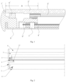
- FIG. 2 it is a structural schematic diagram of an interactive intelligent board in an embodiment of the present disclosure.
- the interactive intelligent board includes a frame 1, a touch display assembly 2, an optical diaphragm 3, a diffuser plate 4, a luminous assembly 5, and a backplane 6;
- a display surface of the touch display assembly 2 faces the front of the interactive intelligent board.
- the front of the interactive intelligent board disclosed in this scheme refers to a side facing the user for displaying images, videos, and receiving touch operations.
- the interactive intelligent board body may include a touch recognition positioning module for recognizing a touch command, a control assembly for controlling a display screen of the touch display assembly 2 and responding to touch commands, a microphone for collecting nearby human or environmental sounds, a speaker for playing audio, a camera for collecting image information, a network module for communication, etc., which is not specifically limited and repeated herein.
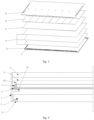
- FIG. 3 it is a schematic diagram of an assembly manner in an embodiment of the present disclosure.
- the installation manner of an interactive intelligent board in an embodiment of the present disclosure is as follows: firstly, placing an outer side of the first fixing part 11 of the frame 1 downwards, and then bonding the touch display assembly 2 onto an inner side of the first fixing part 11 through adhesive.
- the inner side of the first fixing part 11 is a side close to the display surface, the inner side of the first fixing part 11 is a side close to the second fixing part 12; the optical diaphragm and the diffuser plate 4 are arranged on a side of the second fixing part 12 being away from the first fixing part 11, and a combination of the luminous assembly 5 and the backplane 6 is successively invertedly arranged on an upward-facing end of the frame 1.
- the upward-facing end of the frame 1 refers to the end of the frame 1 facing upwards when an outer side of the first fixing part 11 of the frame 1 is placed downwards.
- the above installation manner adopts an inverted installation manner, which integrates the frame, the middle frame, and the fixing support in the prior art to the frame 1, thereby reducing the number of assembly components and assembly difficulty, and improving assembly efficiency.
- the interactive intelligent board in the present disclosure is usually a large-sized interactive intelligent board, of which a size is larger than 75 inches, so as to provide a better experience for multiplayer touching and viewing.
- large-sized interactive intelligent boards are usually installed on walls or supported by supports. Due to the large size of their front face, if the thickness is also too large, it will create a heavy and bulky visual effect, which will greatly affect a visual experience of users.
- the structure of the interactive intelligent board in the present disclosure can not only improve assembly efficiency, but also reduce structures of the necessary fixing support 6' of the glass cover plate and the middle frame 8' in existing interactive intelligent boards, which greatly reduces the thickness of the interactive intelligent board.
- When installed on the wall or placed on the support it is possible to avoid users from producing bulky visual effects, greatly improving the visual experience of the user.
- the first fixing part 11 arranged on the inner wall of the frame 1 is used to fix the touch display assembly 2
- the second fixing part 12 is used to fix the optical diaphragm 3, preventing direct contact between the touch display assembly 2 and the optical diaphragm 3, thereby avoiding the problem of too large adhesive area caused by using a fixing support and glue fixation, and a problem of requiring to add a middle frame to isolate the touch display assembly 2 and the optical diaphragm 3.
- the diffuser plate 4 may convert a point light source or a line light source into a surface light source, so that the brightness of pictures of the interactive intelligent board displayed become much uniform, thereby improving the display effect, and thus improving the visual experience of the user.
- first fixing part 11 extends into the frame along an outer edge of the frame 1.
- the first fixing part 11 does not extend into the frame along the outer edge of the frame 1, a part of side walls of the frame 1 protrudes from a display surface of the first fixing part 11, which means that there will be depressions between the first fixing part 11 and the inner side of the frame 1, causing the problem of difficult cleaning of dirt in the depressions.
- the first fixing part 11 extending along the outer edge of the frame 1 into the frame can make the outer surface of the first fixing part 11 as flush as possible with the edge of the frame, thereby avoiding cleaning problems caused by depressions, and improving the appearance effect of the interactive intelligent board.
- an outer surface of the first fixing part 11 and an outer edge of the frame 1 close to the first fixing part 11 form an outer surface of the frame 1.
- An edge of the touch display assembly 2 being away from the second fixing part 12 is provided with steps, and the steps are clamped with the first fixing part 11 to ensure that the display surface of the touch display assembly 2 is flush with the outer surface of frame 1 after being clamped.
- the outer surface of the touch display assembly 2 is flush with the outer surface of the frame 1, in order to improve the stability of subsequent layers when placed downwards.
- the second fixing part 12 extends into the frame from the middle of the inner side of the frame 1.
- the second fixing part 12 extending from the middle of the inner side of the frame 1 to the inner side of the frame enables the side of the frame 1 being away from the first fixing part 11 to still have sufficient installation space so as to facilitate the installation of the optical diaphragm 3, the diffuser plate 4, the luminous assembly 5, and the backplane 6, thereby improving the convenience of installation.
- a protruded male plug 121 is arranged on a side of the second fixing part 12 being away from the first fixing part 11.
- the optical diaphragm 3 is provided with a first female plug
- the diffuser plate 4 is provided with a second female plug. The male plug 121 is successively inserted into the first female plug and the second female plug.
- FIG. 4 it is a structural schematic diagram of the male plug 121 in the first embodiment of the present disclosure.
- the male plug 121 is adaptively inserted into female plugs of the optical diaphragm 3 and the diffuser plate 4, which can avoid the left and right shaking of the optical diaphragm 3 and the diffuser plate 4, and further improve the stability of fixing the optical diaphragm 3, thereby improving its astigmatism and uniformity effect, and improving the display effect of the interactive intelligent board.
- a length of the male plug 121 may be slightly higher than the total thickness of the optical diaphragm 3 and the diffuser plate 4, so that after the male plug 121 is adaptively inserted into the female plugs of the optical diaphragm 3 and the diffuser plate 4, the top of the male plug 121 extends out of the diffuser plate 4.
- a clamping cap may be used to clamp the top of the male plug 121 and extend out of the part of the diffuser plate 4, so that the clamping cap precisely fixes the optical diaphragm 3 and the diffuser plate 4 on the male plug 121, thereby preventing the optical diaphragm 3 and the diffuser plate 4 from sliding in the thickness direction of the optical diaphragm 3.
- a screw thread may also be arranged at a part where the diffuser plate 4 extends from the top of the male plug 121, and a nut that is suitable for the screw thread may be tightened at a screw thread position, so that the nut precisely fixes the optical diaphragm 3 and the diffuser plate 4 on the male plug 121, which avoids the optical diaphragm 3 and the diffuser plate 4 from sliding in the thickness direction of the optical diaphragm 3.
- Fig. 5 it is a structural schematic diagram of a male plug in an embodiment of the present disclosure.
- the male plug 121 may be several discontinuous sheet shaped protrusions.
- the frame 1 includes four sub-frames 101 located on respective sides, and the four sub-frames 101 are successively connected end to end to form a rectangular frame and form four corners.
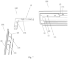
- FIG. 7 it is a structural schematic diagram of a frame in an embodiment of the present disclosure.
- the diagram shows two adjacent sub-frames 101 and a corner fixing member 102.
- the end structure of the remaining sub-frames 101 is the same as that shown in Fig. 7 .
- Both ends of each sub-frame 101 are provided with sub-frame fixing plates 13 (not shown in Fig. 6 ), and sub-frame fixing screw holes 131 are respectively arranged on the sub-frame fixing plates 13.
- the frame 1 further includes four corner fixing members 102 for fixing the sub-frame 101 (not shown in Fig. 6 ).
- Each of the corner fixing members 102 includes two fixing pieces 14, an end of one fixing piece 14 is fixed to an end of the other fixing piece 14 so that a right angle is formed between the two fixing pieces 14; two fixing pieces 14 are respectively provided with corner fixing screw holes 141 having the same size and corresponding positions as the sub-frame fixing screw holes 131.
- the corner fixing members 102 are respectively arranged on the sub-frame fixing plates 13 at the corners, so that the sub-frame fixing screws successively pass through the corner fixing screw holes 141 and the sub-frame fixing screw holes 131, and the corner fixing members 102 are respectively fixed on the corners formed by the sub-frame 101.
- adjacent ends of two sub-frames 101 is pressed tightly to form a vertical corner; the sub-frame fixing plates 13 on the two sub-frames 101 form a right angle corner.
- the corner fixing member 102 is placed above the right angle corner and passes through each corner fixing screw hole 141 of the corner fixing member 102 through the frame fixing screws to fix the two sub-frames 101 downwards, thereby improving the stability and disassembly of frame 1.
- an extension directions of the sub-frame fixing plate 13 is the same as that of the second fixing part 12.
- a groove with a certain width is formed between the sub-frame fixing plate 13 and the second fixing part 12.
- a width of the groove may be set to be consistent with the total thickness of the optical diaphragm 3 and the diffuser plate 4, so that the edges of the optical diaphragm 3 and the diffuser plate 4 may precisely fit into the groove, and further prevent the optical diaphragm 3 and diffuser plate 4 from sliding in the thickness direction of the optical diaphragm 3.
- an edge of the backplane 6 is provided with backplane screw holes; each of the sub-frames 101 is provided with a backplane fixing plate 15, and an arrangement direction of the backplane fixing plate 15 is parallel to an edge of the sub-frame 101; the backplane fixing plate 15 is provided with backplane fixing screw holes 151 having the same shape and corresponding positions as the backplane screw holes, so that the backplane fixing screws successively pass through the backplane screw holes and backplane fixing screw holes 151, and fix the backplane 15 on the rectangular frame formed by the sub-frame 101.
- a backplane fixing plate 15 extending inward is arranged at an end of the frame 1 being away from the first fixing part 11.
- the backplane 6 is fixed to the frame 1 through the backplane fixing screws, thereby enabling the backplane 6 to cover and fix the inner luminous assembly 5, thereby improving the stability of the interactive intelligent board.
- clamping holes may also be arranged on the backplane 6 and the backplane fixing plate 15, and the backplane 6 may be fixed by other fasteners such as buckles, which will not be repeated herein.
- the backplane fixing plate 15 on the sub-frame 101 has a height difference from the sub-frame fixing plate 13, and the backplane fixing plate 15 is closer to an outer side of the frame 1 so that an outer surface of the corner fixing member 102 is flush with an outer surface of the backplane fixing plate 15 after the corner fixing member 102 is fixed on the rectangular frame.
- the outer surface of the corner fixing member 102 is flush with the outer surface of the backplane fixing plate 15, which allows for more stable placement and fixation of the backplane 6, thereby preventing the backplane 6 from warping or shaking after being installed.
- an edge of the frame close to the backplane fixing plate 15 is slightly higher than the backplane fixing plate 15, so that after the backplane 6 is fixed on the rectangular frame formed by the sub-frame 101, the outer surface of the backplane 6 is flush with the edge of the frame 1 close to the backplane fixing plate 15, which can avoid material waste of the protruding part of the frame 1.
- the touch display assembly 2 includes a LCD screen, a touch capacitor, and a glass cover which are successively stacked.
- the touch display assembly 2 after being assembled, the touch display assembly 2 successively includes a glass cover plate, a touch capacitor, and a LCD screen from the outer surface of the frame 1 to the inner surface.
- the touch display assembly 2, including the glass cover plate is fixed inward by the first fixing part 11, which avoids the problem of requiring a large amount of glue and a large adhesive area to firmly adhere the glass cover plate to the outer side of the frame 1, the width of the black edge of the frame 1 has been greatly reduced while ensuring its fixation and firmness.
- the glass cover is formed of tempered glass, which can greatly improve the robustness of interactive intelligent boards.
- the optical diaphragm 3 includes at least one of a diffuser, a brightness enhancement film (BEF), and a reflector.
- BEF brightness enhancement film
- the optical diaphragm 3 has a three-layer structure.
- the three-layer structure consists of a diffuser, a brightness enhancement film, and a reflector, so that the incident point light source is evenly diffused into a divergent light source, to eliminate light spots generated by the luminous assembly, and broaden an irradiation angle, thereby effectively eliminating the lighting blind spot.
- the touch display assembly is fixed by the first fixing part arranged on the inner wall of the frame, and the optical diaphragm is fixed by the second fixing part to prevent direct contact between the touch display assembly and the optical diaphragm, thereby avoiding the problem of too large adhesive area caused by using a fixing support and glue fixation, and a problem of requiring to add a middle frame to isolate the touch display assembly and the optical diaphragm, thereby solving the problem of a wider frame and a smaller effective display area ratio caused by using the middle frame to press the optical diaphragm in the prior art.
- the first fixing part extending along the outer edge of the frame to the inside of the frame can make the display surface of the first fixing part as flush as possible with the edge of the frame, thereby avoiding cleaning problems caused by depressions, and improving the appearance effect of the interactive intelligent board, and meanwhile improving the convenience of user operation.
Landscapes
- Engineering & Computer Science (AREA)
- Physics & Mathematics (AREA)
- Theoretical Computer Science (AREA)
- General Physics & Mathematics (AREA)
- General Engineering & Computer Science (AREA)
- Computer Hardware Design (AREA)
- Nonlinear Science (AREA)
- Human Computer Interaction (AREA)
- Optics & Photonics (AREA)
- Chemical & Material Sciences (AREA)
- Crystallography & Structural Chemistry (AREA)
- Mathematical Physics (AREA)
- Devices For Indicating Variable Information By Combining Individual Elements (AREA)
- Liquid Crystal (AREA)
- Mounting And Adjusting Of Optical Elements (AREA)
- Illuminated Signs And Luminous Advertising (AREA)
- Position Input By Displaying (AREA)
Abstract
Description
- The present disclosure relates to the field of computer technology, and in particular to an interactive intelligent board.
- An interactive intelligent board is an integrated intelligent apparatus that controls a content displayed on a board through touch technology, thereby achieving human-computer interaction.
- In the prior art, interactive intelligent boards are often packaged with a manner of wrapping an edge with a frame 1', as shown in
Fig. 1 , which is a structural schematic diagram of an interactive intelligent board in the prior art. The interactive intelligent board is successively arranged with a glass cover plate 2', a touch display assembly 3', an optical diaphragm 4', and a backplane 5' within the frame 1'. When a structural edge is wrapped with the frame 1', the glass cover plate 2' mainly relies on a fixing support 6' and adhesive bonding to prevent detachment. Due to the fact that the glass fixing support 6' does not allow direct force on the touch display assembly 3', the glass cover plate 2' needs to protrude a certain width towards the direction of the fixing support 6' for easy adhesion. In order to avoid direct contact between the optical diaphragm 4' and the touch display assembly 3' and protect the touch display assembly 3', it is necessary to add a middle frame 8' and press the optical diaphragm 4' through the middle frame 8' to prevent displacement of the optical diaphragm 4' along the thickness direction of the optical diaphragm 4'. Then the positioning column 7' is riveted on the backplane 5' to fix the optical diaphragm 4', so as to prevent displacement of the optical diaphragm 4' along the width direction of the optical diaphragm 4'. Therefore, based on the above structure, the edges of the interactive intelligent board generates black edges that affect the visual and usage effects of users as shown in Region A inFig. 1 . - The purpose of the present disclosure is to provide an interactive intelligent board having a narrow frame and a large effective display area ratio.
- According to the present disclosure, an interactive intelligent board is provided, which includes a frame, a touch display assembly, an optical diaphragm, a diffuser plate, a luminous assembly, and a backplane;
- where a first fixing part and a second fixing part are arranged on an inner wall of the frame at intervals along a thickness direction of the touch display assembly;
- the touch display assembly is fixed on the first fixing part;
- the optical diaphragm, the diffuser plate, the luminous assembly, and the backplane are successively fixed on a side of the second fixing part being away from the first fixing part.
- The present disclosure provides an interactive intelligent board, in which a first fixing part on the inner wall of the frame fixes the touch display assembly, and a second fixing part fixes the optical diaphragm to prevent direct contact between the touch display assembly and the optical diaphragm, thereby avoiding a problem of too large adhesive area caused by using a fixing support and glue fixation, and a problem of requiring to add a middle frame to isolate the touch display assembly and the optical diaphragm, thereby solving a problem of a wider border and a smaller effective display area ratio caused by the use of a middle frame to press the optical diaphragm in the prior art.
-
-
Fig. 1 is a structural schematic diagram of an interactive intelligent board in the prior art. -
Fig. 2 is a structural schematic diagram of an interactive intelligent board in an embodiment of the present disclosure. -
Fig. 3 is a schematic diagram of an assembly manner in an embodiment of the present disclosure. -
Fig. 4 is a structural schematic diagram of a male plug in an embodiment of the present disclosure. -
Fig. 5 is a structural schematic diagram of a male plug in an embodiment of the present disclosure. -
Fig. 6 is a structural schematic diagram of a frame in an embodiment of the present disclosure. -
Fig. 7 is a structural schematic diagram of a frame in an embodiment of the present disclosure. - In
Fig. 1 :
1. Frame; 2'. Glass cover plate; 3'. Touch display assembly; 4'. Optical diaphragm; 5'. Backplane; 6'. Fixing support; 7'. Positioning column; 8'. Middle frame. - In
Figs. 2 to 7 :
1. Frame; 101. Sub-frame; 102. Corner fixing member; 11. First fixing part; 12. Second fixing part; 121. Male plug; 13. Sub-frame fixing plate; 131. Sub-frame fixing screw hole; 14. Fixing piece; 141. Corner fixing screw hole; 15. Backplane fixing plate; 151. Backplane fixing screw hole; 2. Touch display assembly; 3. Optical diaphragm; 4. Diffuser plate; 5. Luminous assembly; 6. Backplane. - The implementation, functional features, and advantages of the present disclosure will be further explained in conjunction with the embodiments, with reference to the accompanying drawings.
- In order to make the purpose, technical solution, and advantages of the present disclosure clearer, the present disclosure will be described in details hereinafter in conjunction with the accompanying drawings and embodiments. It should be understood that the optional embodiments described herein are only used to explain the present disclosure and are not intended to limit it.
- Those skilled in the art may understand that, unless specifically stated, the singular forms "a", "an", "the above", and "this" used herein may also include the plural forms. It should be further understood that the wording "including" used in the description of the present disclosure refers to the presence of features, integers, steps, operations, elements, units, modules, and/or assemblies, but does not exclude the presence or addition of one or more other features, integers, steps, operations, elements, units, modules, assemblies, and/or their groups. It should be understood that when an element is referred to as "connected" or "coupled" to another element, it can be directly connected or coupled to other elements, or there can also be intermediate elements. In addition, the term "connection" or "coupling" used herein can include wireless connection or wireless coupling. The term "and/or" used herein includes all or any unit and all combinations of one or more associated listed items.
- Those skilled in the art can understand that, unless otherwise defined, all terms used herein (including technical and scientific terms) have the same meaning as ordinary technicians in the field to which the present disclosure belongs. It should also be understood that terms such as those defined in general dictionaries should be understood to have meanings consistent with those in the context of the prior art, and unless specifically defined as such, they will not be interpreted with idealized or overly formal meanings.
- Referring to
Fig. 2 , it is a structural schematic diagram of an interactive intelligent board in an embodiment of the present disclosure. The interactive intelligent board includes aframe 1, atouch display assembly 2, anoptical diaphragm 3, adiffuser plate 4, aluminous assembly 5, and abackplane 6; - a first fixing
part 11 and a second fixingpart 12 are arranged on an inner wall of theframe 1 at intervals along a thickness direction of thetouch display assembly 2; - the
touch display assembly 2 is fixed on the first fixingpart 11; - the
optical diaphragm 3, thediffuser plate 4, theluminous assembly 5, and thebackplane 6 are successively fixed on a side of the second fixingpart 12 being away from the first fixingpart 11. - In an embodiment, a display surface of the
touch display assembly 2 faces the front of the interactive intelligent board. The front of the interactive intelligent board disclosed in this scheme refers to a side facing the user for displaying images, videos, and receiving touch operations. - In an embodiment, the interactive intelligent board body may include a touch recognition positioning module for recognizing a touch command, a control assembly for controlling a display screen of the
touch display assembly 2 and responding to touch commands, a microphone for collecting nearby human or environmental sounds, a speaker for playing audio, a camera for collecting image information, a network module for communication, etc., which is not specifically limited and repeated herein. - In an embodiment, referring to
Fig. 3 , it is a schematic diagram of an assembly manner in an embodiment of the present disclosure. The installation manner of an interactive intelligent board in an embodiment of the present disclosure is as follows: firstly, placing an outer side of the first fixingpart 11 of theframe 1 downwards, and then bonding thetouch display assembly 2 onto an inner side of the first fixingpart 11 through adhesive. The inner side of the first fixingpart 11 is a side close to the display surface, the inner side of the first fixingpart 11 is a side close to the second fixingpart 12; the optical diaphragm and thediffuser plate 4 are arranged on a side of the second fixingpart 12 being away from the first fixingpart 11, and a combination of theluminous assembly 5 and thebackplane 6 is successively invertedly arranged on an upward-facing end of theframe 1. The upward-facing end of theframe 1 refers to the end of theframe 1 facing upwards when an outer side of the first fixingpart 11 of theframe 1 is placed downwards. The above installation manner adopts an inverted installation manner, which integrates the frame, the middle frame, and the fixing support in the prior art to theframe 1, thereby reducing the number of assembly components and assembly difficulty, and improving assembly efficiency. - In an embodiment, due to the fact that interactive intelligent boards are often used in fields such as group meetings, multiplayer learning, and multiplayer games, an implementation of the interactive intelligent board has a high requirement for the size. Alternatively, the interactive intelligent board in the present disclosure is usually a large-sized interactive intelligent board, of which a size is larger than 75 inches, so as to provide a better experience for multiplayer touching and viewing. However, such large-sized interactive intelligent boards are usually installed on walls or supported by supports. Due to the large size of their front face, if the thickness is also too large, it will create a heavy and bulky visual effect, which will greatly affect a visual experience of users. The structure of the interactive intelligent board in the present disclosure can not only improve assembly efficiency, but also reduce structures of the necessary fixing support 6' of the glass cover plate and the middle frame 8' in existing interactive intelligent boards, which greatly reduces the thickness of the interactive intelligent board. When installed on the wall or placed on the support, it is possible to avoid users from producing bulky visual effects, greatly improving the visual experience of the user.
- In an embodiment, the first fixing
part 11 arranged on the inner wall of theframe 1 is used to fix thetouch display assembly 2, and the second fixingpart 12 is used to fix theoptical diaphragm 3, preventing direct contact between thetouch display assembly 2 and theoptical diaphragm 3, thereby avoiding the problem of too large adhesive area caused by using a fixing support and glue fixation, and a problem of requiring to add a middle frame to isolate thetouch display assembly 2 and theoptical diaphragm 3. - In an embodiment, the
diffuser plate 4 may convert a point light source or a line light source into a surface light source, so that the brightness of pictures of the interactive intelligent board displayed become much uniform, thereby improving the display effect, and thus improving the visual experience of the user. - Furthermore, the first fixing
part 11 extends into the frame along an outer edge of theframe 1. - Alternatively, if the first fixing
part 11 does not extend into the frame along the outer edge of theframe 1, a part of side walls of theframe 1 protrudes from a display surface of the first fixingpart 11, which means that there will be depressions between the first fixingpart 11 and the inner side of theframe 1, causing the problem of difficult cleaning of dirt in the depressions. The first fixingpart 11 extending along the outer edge of theframe 1 into the frame can make the outer surface of the first fixingpart 11 as flush as possible with the edge of the frame, thereby avoiding cleaning problems caused by depressions, and improving the appearance effect of the interactive intelligent board. - Furthermore, an outer surface of the first fixing
part 11 and an outer edge of theframe 1 close to the first fixingpart 11 form an outer surface of theframe 1. An edge of thetouch display assembly 2 being away from the second fixingpart 12 is provided with steps, and the steps are clamped with the first fixingpart 11 to ensure that the display surface of thetouch display assembly 2 is flush with the outer surface offrame 1 after being clamped. - In an embodiment, due to require inverted installation of each layer in the present disclosure, the outer surface of the
touch display assembly 2 is flush with the outer surface of theframe 1, in order to improve the stability of subsequent layers when placed downwards. - Furthermore, the second fixing
part 12 extends into the frame from the middle of the inner side of theframe 1. - In an embodiment, the second fixing
part 12 extending from the middle of the inner side of theframe 1 to the inner side of the frame enables the side of theframe 1 being away from the first fixingpart 11 to still have sufficient installation space so as to facilitate the installation of theoptical diaphragm 3, thediffuser plate 4, theluminous assembly 5, and thebackplane 6, thereby improving the convenience of installation. - Furthermore, a protruded
male plug 121 is arranged on a side of the second fixingpart 12 being away from the first fixingpart 11. Theoptical diaphragm 3 is provided with a first female plug, and thediffuser plate 4 is provided with a second female plug. Themale plug 121 is successively inserted into the first female plug and the second female plug. - In an embodiment, referring to
Fig. 4 , it is a structural schematic diagram of themale plug 121 in the first embodiment of the present disclosure. Themale plug 121 is adaptively inserted into female plugs of theoptical diaphragm 3 and thediffuser plate 4, which can avoid the left and right shaking of theoptical diaphragm 3 and thediffuser plate 4, and further improve the stability of fixing theoptical diaphragm 3, thereby improving its astigmatism and uniformity effect, and improving the display effect of the interactive intelligent board. - In an embodiment, a length of the
male plug 121 may be slightly higher than the total thickness of theoptical diaphragm 3 and thediffuser plate 4, so that after themale plug 121 is adaptively inserted into the female plugs of theoptical diaphragm 3 and thediffuser plate 4, the top of themale plug 121 extends out of thediffuser plate 4. In actual production, a clamping cap may be used to clamp the top of themale plug 121 and extend out of the part of thediffuser plate 4, so that the clamping cap precisely fixes theoptical diaphragm 3 and thediffuser plate 4 on themale plug 121, thereby preventing theoptical diaphragm 3 and thediffuser plate 4 from sliding in the thickness direction of theoptical diaphragm 3. After thebackplane 6 is fixed on the frame, a fixed width gap is maintained between thebackplane 6 and theoptical diaphragm 3 to form a mixed light distance. In addition, a screw thread may also be arranged at a part where thediffuser plate 4 extends from the top of themale plug 121, and a nut that is suitable for the screw thread may be tightened at a screw thread position, so that the nut precisely fixes theoptical diaphragm 3 and thediffuser plate 4 on themale plug 121, which avoids theoptical diaphragm 3 and thediffuser plate 4 from sliding in the thickness direction of theoptical diaphragm 3. - Preferably, referring to
Fig. 5 , it is a structural schematic diagram of a male plug in an embodiment of the present disclosure. Themale plug 121 may be several discontinuous sheet shaped protrusions. - Furthermore, referring to
Fig. 6 , it is a structural schematic diagram of a frame in an embodiment of the present disclosure. Theframe 1 includes foursub-frames 101 located on respective sides, and the foursub-frames 101 are successively connected end to end to form a rectangular frame and form four corners. - Referring to
Fig. 7 , it is a structural schematic diagram of a frame in an embodiment of the present disclosure. For ease of description, the diagram shows twoadjacent sub-frames 101 and acorner fixing member 102. The end structure of the remainingsub-frames 101 is the same as that shown inFig. 7 . Both ends of each sub-frame 101 are provided with sub-frame fixing plates 13 (not shown inFig. 6 ), and sub-frame fixingscrew holes 131 are respectively arranged on thesub-frame fixing plates 13. - The
frame 1 further includes fourcorner fixing members 102 for fixing the sub-frame 101 (not shown inFig. 6 ). - Each of the
corner fixing members 102 includes two fixingpieces 14, an end of one fixingpiece 14 is fixed to an end of the other fixingpiece 14 so that a right angle is formed between the two fixingpieces 14; two fixingpieces 14 are respectively provided with corner fixingscrew holes 141 having the same size and corresponding positions as the sub-frame fixing screw holes 131. - The
corner fixing members 102 are respectively arranged on thesub-frame fixing plates 13 at the corners, so that the sub-frame fixing screws successively pass through the corner fixingscrew holes 141 and the sub-frame fixing screw holes 131, and thecorner fixing members 102 are respectively fixed on the corners formed by thesub-frame 101. - In an embodiment, referring to
Fig. 7 , adjacent ends of twosub-frames 101 is pressed tightly to form a vertical corner; thesub-frame fixing plates 13 on the twosub-frames 101 form a right angle corner. At this time, thecorner fixing member 102 is placed above the right angle corner and passes through each corner fixingscrew hole 141 of thecorner fixing member 102 through the frame fixing screws to fix the twosub-frames 101 downwards, thereby improving the stability and disassembly offrame 1. - In an embodiment, referring to
Fig. 7 , an extension directions of thesub-frame fixing plate 13 is the same as that of the second fixingpart 12. At this time, a groove with a certain width is formed between thesub-frame fixing plate 13 and the second fixingpart 12. Alternatively, a width of the groove may be set to be consistent with the total thickness of theoptical diaphragm 3 and thediffuser plate 4, so that the edges of theoptical diaphragm 3 and thediffuser plate 4 may precisely fit into the groove, and further prevent theoptical diaphragm 3 anddiffuser plate 4 from sliding in the thickness direction of theoptical diaphragm 3. - Furthermore, an edge of the
backplane 6 is provided with backplane screw holes; each of thesub-frames 101 is provided with abackplane fixing plate 15, and an arrangement direction of thebackplane fixing plate 15 is parallel to an edge of thesub-frame 101; thebackplane fixing plate 15 is provided with backplane fixingscrew holes 151 having the same shape and corresponding positions as the backplane screw holes, so that the backplane fixing screws successively pass through the backplane screw holes and backplane fixing screw holes 151, and fix thebackplane 15 on the rectangular frame formed by thesub-frame 101. - In an embodiment, referring to
Fig. 7 , abackplane fixing plate 15 extending inward is arranged at an end of theframe 1 being away from the first fixingpart 11. Thebackplane 6 is fixed to theframe 1 through the backplane fixing screws, thereby enabling thebackplane 6 to cover and fix the innerluminous assembly 5, thereby improving the stability of the interactive intelligent board. - Preferably, in the optional implementation process, in addition to screws, clamping holes may also be arranged on the
backplane 6 and thebackplane fixing plate 15, and thebackplane 6 may be fixed by other fasteners such as buckles, which will not be repeated herein. - Furthermore, the
backplane fixing plate 15 on thesub-frame 101 has a height difference from thesub-frame fixing plate 13, and thebackplane fixing plate 15 is closer to an outer side of theframe 1 so that an outer surface of thecorner fixing member 102 is flush with an outer surface of thebackplane fixing plate 15 after thecorner fixing member 102 is fixed on the rectangular frame. - In an embodiment, after the installation of the
corner fixing member 102, the outer surface of thecorner fixing member 102 is flush with the outer surface of thebackplane fixing plate 15, which allows for more stable placement and fixation of thebackplane 6, thereby preventing thebackplane 6 from warping or shaking after being installed. - Preferably, an edge of the frame close to the
backplane fixing plate 15 is slightly higher than thebackplane fixing plate 15, so that after thebackplane 6 is fixed on the rectangular frame formed by thesub-frame 101, the outer surface of thebackplane 6 is flush with the edge of theframe 1 close to thebackplane fixing plate 15, which can avoid material waste of the protruding part of theframe 1. Moreover, during the assembly process, it is necessary to extend a mechanical or human hand into an inner side of theframe 1 to place various assemblies, so that theframe 1 is flush with the outer surface of thebackplane 6, which can also reduce a blocking height of theframe 1, thereby reducing the difficulty of being assembled. - Furthermore, the
touch display assembly 2 includes a LCD screen, a touch capacitor, and a glass cover which are successively stacked. - In an embodiment, after being assembled, the
touch display assembly 2 successively includes a glass cover plate, a touch capacitor, and a LCD screen from the outer surface of theframe 1 to the inner surface. At this time, thetouch display assembly 2, including the glass cover plate, is fixed inward by the first fixingpart 11, which avoids the problem of requiring a large amount of glue and a large adhesive area to firmly adhere the glass cover plate to the outer side of theframe 1, the width of the black edge of theframe 1 has been greatly reduced while ensuring its fixation and firmness. - Preferably, the glass cover is formed of tempered glass, which can greatly improve the robustness of interactive intelligent boards.
- Further, the
optical diaphragm 3 includes at least one of a diffuser, a brightness enhancement film (BEF), and a reflector. - Preferably, the
optical diaphragm 3 has a three-layer structure. The three-layer structure consists of a diffuser, a brightness enhancement film, and a reflector, so that the incident point light source is evenly diffused into a divergent light source, to eliminate light spots generated by the luminous assembly, and broaden an irradiation angle, thereby effectively eliminating the lighting blind spot. - In summary, for the interactive intelligent board according to the embodiment of the present disclosure, the touch display assembly is fixed by the first fixing part arranged on the inner wall of the frame, and the optical diaphragm is fixed by the second fixing part to prevent direct contact between the touch display assembly and the optical diaphragm, thereby avoiding the problem of too large adhesive area caused by using a fixing support and glue fixation, and a problem of requiring to add a middle frame to isolate the touch display assembly and the optical diaphragm, thereby solving the problem of a wider frame and a smaller effective display area ratio caused by using the middle frame to press the optical diaphragm in the prior art. The first fixing part extending along the outer edge of the frame to the inside of the frame can make the display surface of the first fixing part as flush as possible with the edge of the frame, thereby avoiding cleaning problems caused by depressions, and improving the appearance effect of the interactive intelligent board, and meanwhile improving the convenience of user operation. By making the outer surface of the touch display assembly be flush with the outer surface of the frame, it is easy to improve the stability of subsequent layers when placed downwards. By arranging a male plug on the second fixing part and corresponding female plugs on the optical diaphragm and diffuser plate, which can avoid left and right shaking of the optical diaphragm and diffuser plate, further improving the stability of fixing the optical diaphragm, thereby improving its astigmatism and uniformity effects, and further improving the display effect of the touch display assembly. Fixing the frame and the backplane by fastening screws can improve the stability of the structure of the interactive intelligent board, and improve the installation convenience and efficiency.
- The above are only preferred embodiments of the present disclosure and do not limit the patent scope of the present disclosure. Any equivalent structure or equivalent process transformation made by using the description and accompanying drawings of the present disclosure, or directly or indirectly applied in other related technical fields, are equally included in the claimed scope of the present disclosure.
Claims (10)
- An interactive intelligent board, comprising:a frame;a touch display assembly;an optical diaphragm;a diffuser plate;a luminous assembly; anda backplane,wherein a first fixing part and a second fixing part are arranged on an inner wall of the frame at intervals along a thickness direction of the touch display assembly;the touch display assembly is fixed on the first fixing part;the optical diaphragm, the diffuser plate, the luminous assembly, and the backplane are successively fixed on a side of the second fixing part being away from the first fixing part.
- The interactive intelligent board of claim 1, wherein the first fixing part extends into the frame along an outer edge of the frame.
- The interactive intelligent board of claim 2, wherein an outer surface of the first fixing part and an outer edge of the frame close to the first fixing part form an outer surface of the frame, an edge of the touch display assembly being away from the second fixing part is provided with steps, and the steps are clamped with the first fixing part so that a display surface of the touch display assembly is flush with the outer surface of frame after being clamped.
- The interactive intelligent board of claim 1, wherein the second fixing part extends into the frame from the middle of the inner side of the frame.
- The interactive intelligent board of claim 4, wherein a protruded male plug is arranged on a side of the second fixing part being away from the first fixing part; the optical diaphragm is provided with a first female plug, and the diffuser plate is provided with a second female plug, the male plug is successively inserted into the first female plug and the second female plug.
- The interactive intelligent board of claim 1, wherein the frame includes four sub-frames located on respective sides, the four sub-frames are successively connected end to end to form a rectangular frame and form four corners;both ends of each of the sub-frames are provided with sub-frame fixing plates, and sub-frame fixing screw holes are respectively arranged on the sub-frame fixing plates;the frame further comprises four corner fixing members for fixing the sub-frames;each of the corner fixing members includes two fixing pieces, an end of one of the two fixing pieces is fixed to an end of the other one of the two fixing pieces so that a right angle is formed between the two fixing pieces; the two fixing pieces are respectively provided with corner fixing screw holes having the same size and corresponding positions as the sub-frame fixing screw holes;the corner fixing members are respectively arranged on the sub-frame fixing plates at the corners, so that the sub-frame fixing screws successively pass through the corner fixing screw holes and the sub-frame fixing screw holes, and the corner fixing members are respectively fixed on the corners formed by the sub-frames.
- The interactive intelligent board of claim 6, wherein an edge of the backplane is provided with backplane screw holes;
each of the sub-frames is provided with a backplane fixing plate, and an arrangement direction of the backplane fixing plate is parallel to an edge of the sub-frame; the backplane fixing plate is provided with backplane fixing screw holes having the same shape and corresponding positions as the backplane screw holes, so that the backplane fixing screws successively pass through the backplane screw holes and the backplane fixing screw holes, and fix the backplane on a rectangular frame formed by the sub-frames. - The interactive intelligent board of claim 7, wherein the backplane fixing plate on the sub-frame has a height difference from the sub-frame fixing plate, and the backplane fixing plate is closer to an outer side of the frame so that an outer surface of the corner fixing member is flush with an outer surface of the backplane fixing plate after the corner fixing member is fixed on the rectangular frame.
- The interactive intelligent board of claim 1, wherein the touch display assembly comprises a LCD screen, a touch capacitor, and a glass cover which are successively stacked.
- The interactive intelligent board of claim 1, wherein the optical diaphragm comprises at least one of a diffuser, a brightness enhancement film, and a reflector.
Applications Claiming Priority (1)
| Application Number | Priority Date | Filing Date | Title |
|---|---|---|---|
| PCT/CN2021/091729 WO2022227078A1 (en) | 2021-04-30 | 2021-04-30 | Interactive smart tablet |
Publications (2)
| Publication Number | Publication Date |
|---|---|
| EP4270145A1 true EP4270145A1 (en) | 2023-11-01 |
| EP4270145A4 EP4270145A4 (en) | 2024-02-21 |
Family
ID=83847606
Family Applications (1)
| Application Number | Title | Priority Date | Filing Date |
|---|---|---|---|
| EP21938552.3A Pending EP4270145A4 (en) | 2021-04-30 | 2021-04-30 | Interactive smart tablet |
Country Status (6)
| Country | Link |
|---|---|
| US (1) | US12253751B2 (en) |
| EP (1) | EP4270145A4 (en) |
| JP (1) | JP7669614B2 (en) |
| KR (1) | KR102864581B1 (en) |
| CN (1) | CN115836267A (en) |
| WO (1) | WO2022227078A1 (en) |
Family Cites Families (20)
| Publication number | Priority date | Publication date | Assignee | Title |
|---|---|---|---|---|
| JP3499419B2 (en) * | 1997-11-11 | 2004-02-23 | 河口湖精密株式会社 | Liquid crystal display |
| KR101376656B1 (en) * | 2008-08-13 | 2014-03-20 | 엘지디스플레이 주식회사 | Liquid crystal display device |
| WO2010146931A1 (en) * | 2009-06-17 | 2010-12-23 | シャープ株式会社 | Display device and television receiver |
| JP5554202B2 (en) | 2010-10-13 | 2014-07-23 | 株式会社ジャパンディスプレイ | Liquid crystal display |
| JP2014102476A (en) | 2012-11-22 | 2014-06-05 | Japan Display Central Co Ltd | Liquid crystal display device |
| CN102998846B (en) * | 2012-12-12 | 2016-03-30 | 深圳市华星光电技术有限公司 | A kind of narrow frame Liquid Crystal Module and glue frame thereof |
| US20140268654A1 (en) * | 2013-03-15 | 2014-09-18 | C-Marine Dynamics, Inc. | Adaptable bezel assembly for extreme service conditions |
| JP2014178552A (en) | 2013-03-15 | 2014-09-25 | Japan Display Central Co Ltd | Liquid crystal display device |
| JP6088339B2 (en) | 2013-04-23 | 2017-03-01 | 京セラ株式会社 | Liquid crystal display |
| JP2015153320A (en) * | 2014-02-18 | 2015-08-24 | 大日本印刷株式会社 | Front protective plate for display device, and display device |
| CN104570482A (en) * | 2015-01-04 | 2015-04-29 | 京东方科技集团股份有限公司 | Backlight module, display device and manufacturing method of display device |
| CN206162012U (en) * | 2016-11-10 | 2017-05-10 | 合肥鑫晟光电科技有限公司 | Backlight module and display device |
| US10768460B2 (en) * | 2016-12-27 | 2020-09-08 | Panasonic Intellectual Property Management Co., Ltd. | Display device |
| CN111133371B (en) * | 2017-09-26 | 2022-08-19 | Lg电子株式会社 | Display device |
| CN109375835B (en) * | 2018-12-03 | 2022-08-02 | 海信视像科技股份有限公司 | Touch control display device |
| CN209356789U (en) * | 2019-01-04 | 2019-09-06 | 京东方科技集团股份有限公司 | Display device |
| CN210090872U (en) * | 2019-06-19 | 2020-02-18 | 武汉华星光电技术有限公司 | A liquid crystal display device |
| CN112305810B (en) * | 2019-07-26 | 2024-08-06 | 京东方科技集团股份有限公司 | Backlight module, display device and assembly method of display device |
| CN210515083U (en) * | 2019-09-12 | 2020-05-12 | 广州视源电子科技股份有限公司 | Intelligent interactive flat plate |
| CN112255840A (en) * | 2020-11-04 | 2021-01-22 | 深圳市柯瑞光电科技有限公司 | LED backlight source for hyperboloid cell-phone |
-
2021
- 2021-04-30 JP JP2023564418A patent/JP7669614B2/en active Active
- 2021-04-30 US US18/285,414 patent/US12253751B2/en active Active
- 2021-04-30 EP EP21938552.3A patent/EP4270145A4/en active Pending
- 2021-04-30 KR KR1020237035109A patent/KR102864581B1/en active Active
- 2021-04-30 WO PCT/CN2021/091729 patent/WO2022227078A1/en not_active Ceased
- 2021-04-30 CN CN202180040841.3A patent/CN115836267A/en active Pending
Also Published As
| Publication number | Publication date |
|---|---|
| WO2022227078A1 (en) | 2022-11-03 |
| CN115836267A (en) | 2023-03-21 |
| JP2024515200A (en) | 2024-04-05 |
| JP7669614B2 (en) | 2025-04-30 |
| US20240184154A1 (en) | 2024-06-06 |
| KR20230156133A (en) | 2023-11-13 |
| EP4270145A4 (en) | 2024-02-21 |
| US12253751B2 (en) | 2025-03-18 |
| KR102864581B1 (en) | 2025-09-26 |
Similar Documents
| Publication | Publication Date | Title |
|---|---|---|
| CN103543543B (en) | Frame-free liquid crystal display device | |
| WO2021063080A1 (en) | Display main body and assembled intelligent interactive panel | |
| WO2018090733A1 (en) | Frame structure of interactive intelligent panel, and interactive intelligent panel | |
| CN202522806U (en) | Fixed structure of display optical diaphragm | |
| CN114740655A (en) | Backlight module and display device | |
| KR101598372B1 (en) | Liquid crystal display device | |
| CN107490888B (en) | a display device | |
| WO2021063081A1 (en) | Direct-type backlight module, liquid crystal display screen, and terminal device | |
| CN206249167U (en) | Frame structure of interactive intelligent panel and interactive intelligent panel | |
| US8425069B2 (en) | Lighting device, display device and television receiver | |
| US12253751B2 (en) | Intelligent interactive board | |
| CN216411803U (en) | Backlight module, display module and display device | |
| KR20130106119A (en) | Liquid crystal display device | |
| WO2023109237A1 (en) | Display module and display device | |
| CN102141646B (en) | Backlight module and light guide plate module | |
| CN210516007U (en) | Display main body and spliced intelligent interactive panel comprising same | |
| CN209433160U (en) | A kind of film fixing structure, backlight module and display device | |
| KR101790061B1 (en) | Liquid crystal display device | |
| KR20090072294A (en) | LCD Display | |
| CN117456843A (en) | A splicing screen structure, display and electronic equipment | |
| CN203176948U (en) | Back light module and display device | |
| CN210515978U (en) | Interactive all-in-one machine | |
| CN202160238U (en) | LCD TV | |
| CN219285549U (en) | A mounting component and display device | |
| CN212694612U (en) | Intelligent blackboard capable of being pushed and pulled |
Legal Events
| Date | Code | Title | Description |
|---|---|---|---|
| STAA | Information on the status of an ep patent application or granted ep patent |
Free format text: STATUS: THE INTERNATIONAL PUBLICATION HAS BEEN MADE |
|
| PUAI | Public reference made under article 153(3) epc to a published international application that has entered the european phase |
Free format text: ORIGINAL CODE: 0009012 |
|
| STAA | Information on the status of an ep patent application or granted ep patent |
Free format text: STATUS: REQUEST FOR EXAMINATION WAS MADE |
|
| 17P | Request for examination filed |
Effective date: 20230724 |
|
| AK | Designated contracting states |
Kind code of ref document: A1 Designated state(s): AL AT BE BG CH CY CZ DE DK EE ES FI FR GB GR HR HU IE IS IT LI LT LU LV MC MK MT NL NO PL PT RO RS SE SI SK SM TR |
|
| A4 | Supplementary search report drawn up and despatched |
Effective date: 20240123 |
|
| RIC1 | Information provided on ipc code assigned before grant |
Ipc: G02F 1/1333 20060101ALI20240117BHEP Ipc: G06F 1/16 20060101AFI20240117BHEP |
|
| DAV | Request for validation of the european patent (deleted) | ||
| DAX | Request for extension of the european patent (deleted) |