EP4269972A1 - Non-contact pressure measurement system of balloon catheter and non-contact pressure measurement method of balloon catheter, using same - Google Patents
Non-contact pressure measurement system of balloon catheter and non-contact pressure measurement method of balloon catheter, using same Download PDFInfo
- Publication number
- EP4269972A1 EP4269972A1 EP21911225.7A EP21911225A EP4269972A1 EP 4269972 A1 EP4269972 A1 EP 4269972A1 EP 21911225 A EP21911225 A EP 21911225A EP 4269972 A1 EP4269972 A1 EP 4269972A1
- Authority
- EP
- European Patent Office
- Prior art keywords
- tube part
- saline solution
- tube
- amount
- expansion
- Prior art date
- Legal status (The legal status is an assumption and is not a legal conclusion. Google has not performed a legal analysis and makes no representation as to the accuracy of the status listed.)
- Pending
Links
Images




Classifications
-
- G—PHYSICS
- G01—MEASURING; TESTING
- G01L—MEASURING FORCE, STRESS, TORQUE, WORK, MECHANICAL POWER, MECHANICAL EFFICIENCY, OR FLUID PRESSURE
- G01L9/00—Measuring steady of quasi-steady pressure of fluid or fluent solid material by electric or magnetic pressure-sensitive elements; Transmitting or indicating the displacement of mechanical pressure-sensitive elements, used to measure the steady or quasi-steady pressure of a fluid or fluent solid material, by electric or magnetic means
- G01L9/12—Measuring steady of quasi-steady pressure of fluid or fluent solid material by electric or magnetic pressure-sensitive elements; Transmitting or indicating the displacement of mechanical pressure-sensitive elements, used to measure the steady or quasi-steady pressure of a fluid or fluent solid material, by electric or magnetic means by making use of variations in capacitance, i.e. electric circuits therefor
-
- G—PHYSICS
- G01—MEASURING; TESTING
- G01L—MEASURING FORCE, STRESS, TORQUE, WORK, MECHANICAL POWER, MECHANICAL EFFICIENCY, OR FLUID PRESSURE
- G01L9/00—Measuring steady of quasi-steady pressure of fluid or fluent solid material by electric or magnetic pressure-sensitive elements; Transmitting or indicating the displacement of mechanical pressure-sensitive elements, used to measure the steady or quasi-steady pressure of a fluid or fluent solid material, by electric or magnetic means
- G01L9/0033—Transmitting or indicating the displacement of bellows by electric, electromechanical, magnetic, or electromagnetic means
- G01L9/0039—Transmitting or indicating the displacement of bellows by electric, electromechanical, magnetic, or electromagnetic means using photoelectric means
-
- A—HUMAN NECESSITIES
- A61—MEDICAL OR VETERINARY SCIENCE; HYGIENE
- A61B—DIAGNOSIS; SURGERY; IDENTIFICATION
- A61B17/00—Surgical instruments, devices or methods
- A61B17/12—Surgical instruments, devices or methods for ligaturing or otherwise compressing tubular parts of the body, e.g. blood vessels or umbilical cord
- A61B17/12022—Occluding by internal devices, e.g. balloons or releasable wires
- A61B17/12131—Occluding by internal devices, e.g. balloons or releasable wires characterised by the type of occluding device
- A61B17/12136—Balloons
-
- A—HUMAN NECESSITIES
- A61—MEDICAL OR VETERINARY SCIENCE; HYGIENE
- A61B—DIAGNOSIS; SURGERY; IDENTIFICATION
- A61B17/00—Surgical instruments, devices or methods
- A61B17/42—Gynaecological or obstetrical instruments or methods
-
- A—HUMAN NECESSITIES
- A61—MEDICAL OR VETERINARY SCIENCE; HYGIENE
- A61M—DEVICES FOR INTRODUCING MEDIA INTO, OR ONTO, THE BODY; DEVICES FOR TRANSDUCING BODY MEDIA OR FOR TAKING MEDIA FROM THE BODY; DEVICES FOR PRODUCING OR ENDING SLEEP OR STUPOR
- A61M25/00—Catheters; Hollow probes
- A61M25/10—Balloon catheters
- A61M25/1018—Balloon inflating or inflation-control devices
- A61M25/10181—Means for forcing inflation fluid into the balloon
-
- G—PHYSICS
- G01—MEASURING; TESTING
- G01L—MEASURING FORCE, STRESS, TORQUE, WORK, MECHANICAL POWER, MECHANICAL EFFICIENCY, OR FLUID PRESSURE
- G01L17/00—Devices or apparatus for measuring tyre pressure or the pressure in other inflated bodies
- G01L17/005—Devices or apparatus for measuring tyre pressure or the pressure in other inflated bodies using a sensor contacting the exterior surface, e.g. for measuring deformation
-
- G—PHYSICS
- G01—MEASURING; TESTING
- G01L—MEASURING FORCE, STRESS, TORQUE, WORK, MECHANICAL POWER, MECHANICAL EFFICIENCY, OR FLUID PRESSURE
- G01L9/00—Measuring steady of quasi-steady pressure of fluid or fluent solid material by electric or magnetic pressure-sensitive elements; Transmitting or indicating the displacement of mechanical pressure-sensitive elements, used to measure the steady or quasi-steady pressure of a fluid or fluent solid material, by electric or magnetic means
- G01L9/0091—Transmitting or indicating the displacement of liquid mediums by electrical, electromechanical, magnetic or electromagnetic means
-
- A—HUMAN NECESSITIES
- A61—MEDICAL OR VETERINARY SCIENCE; HYGIENE
- A61B—DIAGNOSIS; SURGERY; IDENTIFICATION
- A61B17/00—Surgical instruments, devices or methods
- A61B17/12—Surgical instruments, devices or methods for ligaturing or otherwise compressing tubular parts of the body, e.g. blood vessels or umbilical cord
- A61B2017/12004—Surgical instruments, devices or methods for ligaturing or otherwise compressing tubular parts of the body, e.g. blood vessels or umbilical cord for haemostasis, for prevention of bleeding
-
- A—HUMAN NECESSITIES
- A61—MEDICAL OR VETERINARY SCIENCE; HYGIENE
- A61B—DIAGNOSIS; SURGERY; IDENTIFICATION
- A61B17/00—Surgical instruments, devices or methods
- A61B17/42—Gynaecological or obstetrical instruments or methods
- A61B2017/4216—Operations on uterus, e.g. endometrium
-
- A—HUMAN NECESSITIES
- A61—MEDICAL OR VETERINARY SCIENCE; HYGIENE
- A61B—DIAGNOSIS; SURGERY; IDENTIFICATION
- A61B90/00—Instruments, implements or accessories specially adapted for surgery or diagnosis and not covered by any of the groups A61B1/00 - A61B50/00, e.g. for luxation treatment or for protecting wound edges
- A61B90/06—Measuring instruments not otherwise provided for
- A61B2090/064—Measuring instruments not otherwise provided for for measuring force, pressure or mechanical tension
-
- A—HUMAN NECESSITIES
- A61—MEDICAL OR VETERINARY SCIENCE; HYGIENE
- A61B—DIAGNOSIS; SURGERY; IDENTIFICATION
- A61B90/00—Instruments, implements or accessories specially adapted for surgery or diagnosis and not covered by any of the groups A61B1/00 - A61B50/00, e.g. for luxation treatment or for protecting wound edges
- A61B90/06—Measuring instruments not otherwise provided for
-
- A—HUMAN NECESSITIES
- A61—MEDICAL OR VETERINARY SCIENCE; HYGIENE
- A61M—DEVICES FOR INTRODUCING MEDIA INTO, OR ONTO, THE BODY; DEVICES FOR TRANSDUCING BODY MEDIA OR FOR TAKING MEDIA FROM THE BODY; DEVICES FOR PRODUCING OR ENDING SLEEP OR STUPOR
- A61M25/00—Catheters; Hollow probes
- A61M2025/0001—Catheters; Hollow probes for pressure measurement
- A61M2025/0002—Catheters; Hollow probes for pressure measurement with a pressure sensor at the distal end
-
- A—HUMAN NECESSITIES
- A61—MEDICAL OR VETERINARY SCIENCE; HYGIENE
- A61M—DEVICES FOR INTRODUCING MEDIA INTO, OR ONTO, THE BODY; DEVICES FOR TRANSDUCING BODY MEDIA OR FOR TAKING MEDIA FROM THE BODY; DEVICES FOR PRODUCING OR ENDING SLEEP OR STUPOR
- A61M2205/00—General characteristics of the apparatus
- A61M2205/33—Controlling, regulating or measuring
- A61M2205/3306—Optical measuring means
-
- A—HUMAN NECESSITIES
- A61—MEDICAL OR VETERINARY SCIENCE; HYGIENE
- A61M—DEVICES FOR INTRODUCING MEDIA INTO, OR ONTO, THE BODY; DEVICES FOR TRANSDUCING BODY MEDIA OR FOR TAKING MEDIA FROM THE BODY; DEVICES FOR PRODUCING OR ENDING SLEEP OR STUPOR
- A61M2205/00—General characteristics of the apparatus
- A61M2205/33—Controlling, regulating or measuring
- A61M2205/3327—Measuring
-
- A—HUMAN NECESSITIES
- A61—MEDICAL OR VETERINARY SCIENCE; HYGIENE
- A61M—DEVICES FOR INTRODUCING MEDIA INTO, OR ONTO, THE BODY; DEVICES FOR TRANSDUCING BODY MEDIA OR FOR TAKING MEDIA FROM THE BODY; DEVICES FOR PRODUCING OR ENDING SLEEP OR STUPOR
- A61M2205/00—General characteristics of the apparatus
- A61M2205/33—Controlling, regulating or measuring
- A61M2205/3331—Pressure; Flow
- A61M2205/3344—Measuring or controlling pressure at the body treatment site
-
- A—HUMAN NECESSITIES
- A61—MEDICAL OR VETERINARY SCIENCE; HYGIENE
- A61M—DEVICES FOR INTRODUCING MEDIA INTO, OR ONTO, THE BODY; DEVICES FOR TRANSDUCING BODY MEDIA OR FOR TAKING MEDIA FROM THE BODY; DEVICES FOR PRODUCING OR ENDING SLEEP OR STUPOR
- A61M2205/00—General characteristics of the apparatus
- A61M2205/33—Controlling, regulating or measuring
- A61M2205/3379—Masses, volumes, levels of fluids in reservoirs, flow rates
- A61M2205/3393—Masses, volumes, levels of fluids in reservoirs, flow rates by weighing the reservoir
-
- A—HUMAN NECESSITIES
- A61—MEDICAL OR VETERINARY SCIENCE; HYGIENE
- A61M—DEVICES FOR INTRODUCING MEDIA INTO, OR ONTO, THE BODY; DEVICES FOR TRANSDUCING BODY MEDIA OR FOR TAKING MEDIA FROM THE BODY; DEVICES FOR PRODUCING OR ENDING SLEEP OR STUPOR
- A61M25/00—Catheters; Hollow probes
- A61M25/10—Balloon catheters
-
- A—HUMAN NECESSITIES
- A61—MEDICAL OR VETERINARY SCIENCE; HYGIENE
- A61M—DEVICES FOR INTRODUCING MEDIA INTO, OR ONTO, THE BODY; DEVICES FOR TRANSDUCING BODY MEDIA OR FOR TAKING MEDIA FROM THE BODY; DEVICES FOR PRODUCING OR ENDING SLEEP OR STUPOR
- A61M25/00—Catheters; Hollow probes
- A61M25/10—Balloon catheters
- A61M25/1018—Balloon inflating or inflation-control devices
- A61M25/10184—Means for controlling or monitoring inflation or deflation
Definitions
- Exemplary embodiments of the present invention relate to a non-contact pressure measurement system of a balloon catheter and a non-contact pressure measurement method of the balloon catheter using the same. More particularly, exemplary embodiments of the present invention relate to a non-contact pressure measurement system of a balloon catheter and a non-contact pressure measurement method of the balloon catheter using the same, capable of measuring the pressure and the amount of saline injection applied to uterine balloon tamponade or uterine balloon catheter among the methods of treating postpartum hemorrhage without contact.
- Postpartum hemorrhage is excessive bleeding within the first 24 hours after childbirth, and may be fatal if not properly treated.
- a hemostasis method using a uterine balloon tamponade or a uterine balloon catheter is mainly used.
- a tube drawn into the human body In particular, in order to inject saline through a balloon catheter for the uterus, a tube drawn into the human body must be used. However, it is very limited to add a separate device or structure for measuring the injection amount or pressure on the tube in order to prevent infection in the human body through the saline solution.
- Exemplary embodiments of the present invention provide a non-contact pressure measurement system of a balloon catheter, capable of measuring the pressure and the amount of saline injection applied to uterine balloon tamponade or uterine balloon catheter among the methods of treating postpartum hemorrhage without contact, so as assist the procedure effectively by enabling accurate measurement while preventing contamination or infection.
- Exemplary embodiments of the present invention also provide a non-contact pressure measurement method of the balloon catheter using the non-contact pressure measurement system of a balloon catheter.
- the system includes a chamber part, a balloon, a tube part, a pump part and a displacement sensor.
- the chamber part stores a saline solution.
- the balloon is disposed inside of a body and is configured to be expanded with supply of the saline solution.
- the tube part is configured to connect the chamber part with the balloon.
- the pump part is configured to control the supply of the saline solution via the tube part.
- the displacement sensor is configured to measure an amount of the expansion of the tube part expanded with the supply of the saline solution, in a predetermined section of the tube part.
- the chamber part may include a weight sensor disposed under the chamber part, and configured to measure a weight of the saline solution stored in the chamber part.
- the pump part may provide the saline solution with a pulse through the tube part, without contacting the saline solution.
- the system may further include an injection amount measuring part configured to measure an amount of the saline solution injected to the balloon through the tube part, based on the weight of the saline solution measured by the weight sensor and the pulse information operated in the pump part.
- the displacement sensor may include a first fixing part configured to fix a first end of the tube part within a predetermined section, a second fixing part configured to fix a second end of the tub part within the predetermined section, and a sensor unit configured to measure the amount of the expansion of the tube part with the supply of the saline solution between the first and second fixing parts.
- the sensor unit may be a displacement sensor configured to measure the amount of the expansion of the tube part using a laser.
- the sensor unit may include a light emitting part disposed at a first side of the tube part and configured to irradiate the laser, and a light receiving part disposed at a second side of the tube part and configured to receiving the laser.
- the displacement sensor may include a base plate at which the first and second fixing parts spaced apart from each other are fixed, a first connector connected to a first end of the tube part and fixed at the first fixing part, and a second connector connected to a second end of the tube part and fixed at the second fixing part.
- the distance between the first and second fixing parts may be changed in the base plate, and a plurality of fixing grooves may be formed at the base plate for the first and second fixing parts to be fixed at different spacing intervals.
- the distance between the first and second fixing parts may be changed in the base plate.
- the sensor array may be configured to measure the amount of the expansion of the tube part at a plurality of positions of the tube parts.
- the system may further include a database in which a relationship between a pressure applied to the tube part and the expansion of the tube part, for the types of the tube part, and a pressure measuring part configured to measure the pressure applied to the tube part, based on the information stored in the database and the amount of the expansion of the tube part measured by the displacement sensor.
- the method includes pre-storing a relationship between a pressure applied to a tube part and an amount of expansion of the tube part, for the types of the tube part, injecting a saline solution stored in a chamber part into the tube part and providing the saline solution to a balloon, measuring an amount of the saline solution injected to the tube part, measuring the amount of the expansion of the tube part with supply of the saline solution, in a predetermined section of the tube part, and measuring the pressure applied to the tube part, based on the pre-stored information and the amount of the expansion of the tube part.
- the entire saline solution supplied to the balloon may be drained into the chamber part, and the injection of the saline solution into the tube part may be stopped.
- saline solution supplied to the balloon located in the body it is possible to measure the pressure or supply amount of saline solution supplied to the balloon located in the body through a non-contact system without direct contact with the saline solution or the tube, so that a procedure based on the experience or subjective judgment of conventional medical staff may be avoided and an objective procedure based on more accurate measurement results may be performed, with preventing problems such infection.
- the amount of saline solution supplied may be accurately measured without contact, based on pulse information of a weight sensor part configured to a chamber part and pump part supplying the saline solution with a pulse.
- the pressure applied to the tube part by the saline solution may be accurately measured by measuring the degree of expansion of the tube part through the displacement sensor.
- the pressure may be derived using the relationship between the pre-stored level of expansion of the tube part and the pressure, as for the expansion level of the tube part measured by the displacement sensor, the pressure at which the saline solution is supplied may be accurately derived even for various types of tubes or various saline supply environments.
- the degree of expansion of the tube part may be accurately measured according to various environmental variables such as the type of the tube part, the type of saline solution, or the pressure or amount of the saline solution applied thereto.
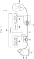
- FIG. 1 is a schematic diagram illustrating a non-contact pressure measurement system according to an example embodiment of the present invention.
- the non-contact pressure measurement system 10 (hereinafter, the system) according to the present example embodiment includes a chamber part 100, a pump part 200, an injection amount measuring part 300, a displacement sensor 400, a pressure measuring part 500, a balloon 600, a controller 700, a database 800 and a tube part 50.
- the chamber part 100 is a chamber forming a predetermined space thereinside, and a saline solution 120 is stored in the space of the chamber part 100.
- the saline solution 120 passes through the tube part 50 and is provided to the balloon 600, and types of the saline solution are not limited.
- the balloon 600 is disposed inside of a body, for example a womb, and is expanded by the saline solution 120 supplied into the balloon 600. Accordingly, as the balloon is expanded, hemostasis may be performed on the part where postpartum bleeding occurs, and it may serve as a so-called uterine balloon tamponade or a uterine balloon catheter.
- an amount of the saline solution 120 and a pressure of the saline solution 120 provided into the balloon 600 are measured.
- objective information on the amount and the pressure of the saline solution 120 is provided, and thus the amount and the pressure of the saline solution 120 for stopping postpartum hemorrhage may be controlled and be uniformly maintained.
- the tube part 50 is extended from the chamber part 100 to the balloon 600, and a portion disposed adjacent to the balloon 600 and inserted into the body should be controlled not to be polluted for preventing the infection.
- a material or a length of the tube part 50 may be changed variously and not to limited to a specific condition.
- the amount and the pressure of the saline solution 120 may be accurately measured using the system 10 as mentioned below, and thus the system 10 may be applied to various kinds of tube parts.
- the weight sensor 110 is disposed under the chamber part 100.
- the weight sensor 110 may be configured to measure the weight of the chamber part 100 and the saline solution 120.
- the weight of the saline solution 120 that is, the weight of the saline solution 120 provided via the tube part 50 may be obtained.
- the information of the weight of the saline solution 120 obtained by the weight sensor 110 may be provided to the injection amount measuring part 300.
- the pump part 200 pumps the saline solution 120, so as for the saline solution 120 to flow into the tube party 50.
- the pump part 200 may be operated by an operation control signal of the controller 700, and the pump part 200 may supply the saline solution 120 toward the balloon 600 based on the control of the controller 700. Alternatively, the pump part 200 may drain the saline solution 120 filled in the balloon 60 into the chamber part 100.
- the pump part 120 pumps the saline solution 120 without contacting the saline solution 120.
- the pump part 120 may be operated with a pulse driving, and then the saline solution 120 may be supplied to the tube part 50 in a predetermined uniform amount.
- the information on the pulse driving of the pump part 120 is provided to the injection amount measuring part 300.
- the injection amount measuring part 300 measures the amount of the saline solution 120 provided via the tube part 50, based on the information of the weight of the saline solution 120 measured by the weight sensor 110, and the information of the pulse in the pulse driving of the pump part 200.
- the amount of the saline solution 120 supplied to the tube part 50 may be obtained.
- the amount of the saline solution 120 supplied to the tube part 50 may be obtained based on the number of the pulse.
- the injection amount measuring part 300 may obtain the amount of the saline solution 120 supplied to the tube part 50 accurately, based on the information on the weight change and the pulse.
- the information on the amount of the saline solution 120 obtained as explained above is provided to the controller 700, and the controller 700 decides whether the amount and the pressure of the saline solution 120 is within a normal amount and a normal pressure respectively, with the information of the pressure of the saline solution 120. Then, the controller 700 controls the operation of the pump part 120.
- the displacement sensor 400 measures the pressure of the saline solution 120 passing through the tube part 50.
- the tube part 50 is designed to be expanded according as the saline solution 120 passes through the tube part 50 in a predetermined section, and then the displacement sensor 400 measures the amount of the expansion of the tube part 50.
- the displacement sensor 400 may measure the pressure of the saline solution 120.
- the pressure measuring part 500 measures the pressure of the saline 120 applied to the tube part 50, based on the information of the expansion of the tube part 50 measured in the displacement sensor 400.
- the displacement sensor 400 merely provides the information of the amount of the expansion of the tube part 50 to the pressure measuring part 500.
- the pressure measuring part 500 uses the information stored in the database 800, to obtain the pressure applied to the tube part 50, that is, the pressure information of the saline solution 120.
- a relationship between the expansion of the tube part and the pressure of the saline solution is pre-stored in the database 800.
- the relationship on various kinds of tube parts may be pre-stored in the database 800.
- the saline solution is supplied to various kinds of tube parts, the pressure is measured using a separate pressure sensor, and the amount of the expansion of the tube parts at the corresponding pressure is measured and is stored in the database 800.
- the amount of the expansion of the tub parts and the pressure information in every case are stored from the simulation environment, and thus the saline solution 120 may be prevented from being infected by outer elements, for example the pressure sensor and so on, in the actual procedure of the operation.
- the pressure information may be easily obtained only by the expansion information of the tube part 50 which may be obtained without direct contact with the saline solution 120.
- the pressure information of the saline solution 120 measured in the pressure measuring part 500 is provided to the controller 700.
- the controller 700 decides whether the pressure is within a range of the normal pressure or not, and when the measured pressure is out of the normal pressure, the controller 700 may stop the operation of the pump part 200.
- FIG. 2A, FIG. 2B and FIG. 2C are plan views illustrating a sensing state of a displacement sensor of FIG. 1
- FIG. 3A, FIG. 3B and FIG. 3C are cross-sectional views taken along a line I-I' of FIG. 2A in the sensing state of the displacement sensor.
- the displacement sensor 400 includes a sensor unit 420, a first fixing part 430 and a second fixing part 440.
- the sensor unit 420 includes a light emitting part 421, a light receiving part 422 and a base frame 423.
- a first end of the tube part 50 is fixed by the first fixing part 430, and a second end of the tube part 50 is fixed by the second fixing part 440, and then the displacement of the tube part 50 expanded according to the passing of the saline solution 120 is measured by the sensor unit 420.
- FIG. 2A and FIG. 3A show the state of the saline solution 120 not passing through the tube part 50, and the displacement of the tube part 50 measured by the sensor unit 420 is an initial state or an initial value.
- the tube part 50 is expanded at the predetermined section between the first and second fixing parts 430 and 440, and then the sensor unit 420 measures the amount of the expansion of the tube part 50.
- the sensor unit 420 measures the amount of the expansion of the tube part 50.
- the information of the amount of the expansion of the tube part 50 is obtained by the sensor unit 420 in a real time, and the obtained information is provided to the pressure measuring part 500.
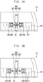
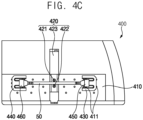
- FIG. 4A is a plan view illustrating the displacement sensor of FIG. 1
- FIG. 4B and FIG. 4C are plan views illustrating examples of extending the length of the tube part.
- the displacement sensor 400 further includes a base plate 410, a first connector 450 and a second connector 460.
- the base plate 410 is a plate extending with a predetermined area, and the first and second fixing parts 430 and 440 and the sensor unit 420 explained above are disposed on the base plate 410.
- a plurality of fixing grooves 411 is formed at the base plate 410 by a predetermined distance, and the first and second fixing parts 430 and 440 adjacent to each other are fixed at the fixing grooves 411 through a fixing unit (not shown).
- the distance between the first and second fixing parts 430 and 440 may be changed variously. As the distance between the first and second fixing parts 430 and 440 changes, a length of the tube part 50 extending between the first and second fixing parts 430 and 440 is also changed.
- the amount of the expansion of the tube part 50 is increased and then the amount of the expansion of the tube part 50 is hard to be measured by the sensor unit 420, in case that the length of the tube part 50 fixed by the first and second fixing parts 430 and 440 is relatively shorter.
- the tube part 50 is relatively rigid and the amount of the expansion of the tube part 500 is relatively smaller, the amount of the expansion of the tube part 50 is decreased and then the amount of the expansion of the tube part 50 is hard to be measured by the sensor unit 420, in case that the length of the tube part 50 fixed by the first and second fixing parts 430 and 440 is relatively longer.
- the distance between the first and second fixing parts 430 and 440 may be controlled variously considering the material of the tube part 50, that is, the amount of the expansion of the tube part 50, the kinds of the saline solution 120 passing through the tube part 50, and so on.
- the sensor unit 420 measures the amount of the expansion of the tube part 50, that is, the displacement of the expansion, and for example, the sensor unit 420 may be a displacement sensor measuring the displacement using a laser.
- the base frame 423 may fixed at the base frame 423, in a direction crossing an extending direction of the tube part 50.
- the light emitting part 421 is disposed at a first side of the tube part 50 and irradiates a laser.
- the light receiving part 422 is disposed at a second side of the tube part 50 and receives the laser which is irradiated from the light emitting part 421, passes through the tube part 50 and then reaches at the light receiving part 422.
- the tube part 50 is extended between the light emitting part 421 and the light receiving part 422.
- the light receiving part 422 measures the amount of the expansion of the tube part 50, based on the laser irradiated from the light emitting part 420 and reaching at the light receiving part 422 with shielded by the tube part 50.
- first and second connectors 450 and 460 may be explained below.
- FIG. 5A and FIG. 5B are plan views illustrating another examples of the displacement sensor of FIG. 1 .
- the sensor units 420 each having the same structure are arranged in parallel with the same distance along a direction perpendicular to the extending direction of the tube part 50.
- the sensor units 420 each having the same structure are arranged in parallel with the same distance along a direction perpendicular to the extending direction of the tube part 50.
- a plurality of sensor units is arranged between the first and second fixing parts 430 and 440 and then forms the sensor array 425 and 426, and thus the amount of the expansion of the tube part 50 may be measured at various positions of the tube part 50 extending between the first and second fixing parts 430 and 440.
- the amount of the expansion of the tube part 50 may be accurately obtained even though the length of the measures length of the tube part 50 increases.
- FIG. 6 is a perspective view illustrating the first and second fixing parts of FIG. 4A .
- FIG. 7 is a perspective view illustrating a fixing state of the first and second connectors and the tube part fixed to the first and second fixing parts.
- the first and second fixing parts 430 and 440 are disposed to face each other and each has the same structure, and then the first fixing part 430 is explained.
- the first fixing part 430 includes a base part 431, an extending part 433 and a clamping part 434.
- the base part 431 forms a base of the first fixing part 430, and is disposed on the base plate 410.
- a pair of the fixing line grooves 432 is formed at the base part 431, and the fixing line grooves 432 are aligned with the fixing grooves 411 at the base plate 410, and thus the first fixing part 430 may be fixed at the base plate 410 through an additional fixing unit (not shown).
- the extending part 433 extends between the pair of the fixing line grooves 432 at an end of the base part 431, and the extending part 433 extends with a predetermined height.
- the clamping part 434 is formed at an end of the extending part 433, and is protruded with a fixing protrusion.
- An inserting portion 435 is formed at a space between the pair of end portions of the clamping part 434.
- the first connector 450 is inserted and fixed, and then the tube part 50 may be fixed via the first and second connectors 450 and 460.
- the extending part 433 is extended with a predetermined height, and then the tube part 50 fixed between the first and second connectors 450 and 460 is also extended upward by a predetermined height from the base plate 410.
- the clamping part 434 has the pair of end portions and forms the inserting portion 435, and thus the first connector 450 positioned at the inserting portion 435 may be stably fixed.
- the first connector 450 is fixed at the inserting portion 435 of the first fixing part 430
- the second connector 460 is fixed at an inserting portion of the second fixing part 440.
- the first connector 450 includes a body portion 451, a supporting portion 452, and a connecting portion 453.
- the supporting portion 452 is extended from the body portion 451 and is fixed at the inserting portion 435 of the first fixing part 430.
- the connecting portion 435 is extended from the supporting portion 452 and is connected to the tube part 50.
- the second connector 460 includes a body portion 461, a supporting portion 462, and a connecting portion 463, like the first connector 450.
- a first end of the tube part 50 is fixed at the first fixing part 430 by the first connector 450, and a second end of the tube part 50 is fixed at the second fixing part 440 by the second connector 460.
- the sensor unit 420 measures the amount of the expansion of the tube part 50 at the predetermined section of the tube part 50.
- the tube part 50 is exampled to be disposed between the first and second fixing parts 430 and 440, but the tube part 50 may be extended to pass through the body portions 451 and 461 of the first and second connectors 450 and 460, as expected referring to FIG. 1 .
- the displacement sensor 400 is positioned at the predetermined section of the tube part 50, so that the amount of the expansion of the tube part 50 at the section may be measured, and then the pressure information of the saline solution 120 passing through the tube part 50 may be obtained.
- the pressure is obtained without the contact, that is, the non-contact type is applied in measuring the saline solution 120, so that the pollution or the infection of the saline solution may be minimized.
- FIG. 8 is a flow chart showing a non-contact pressure measurement method using the non-contact pressure measurement system of FIG. 1 .
- step S10 in the method using the system 10, the relationship between the pressure applied to the tube part and the amount of the expansion of the tube part for various kinds of tube parts, is pre-stored in the database (step S10).
- the saline solution 120 stored in the chamber part 100 is injected to the tube part 50, and then is supplied to the balloon 600 (step S20).
- the information of the weight of the saline solution 120 stored in the chamber part 100 that is the change of the weight of the saline solution 120 according to the supply of the saline solution 120, is measured, and then the measured information is provided to the injection amount measuring part 300.
- the pump part 200 supplies the saline solution 120 to the tube part 50
- the information of the supplying pulse of the pump part 200 is also provided to the injection amount measuring part 300.
- the injection amount measuring part 300 measures the amount of the saline solution 120 supplied into the tube part 50, based on the information of the weight (change) of the saline solution 120 measured by the weight sensor 110, and the information of the pulse of the pump part 200.
- the information of the amount of the saline solution 120 is provided to the controller 700.
- the displacement sensor 400 in the tube part 50 measures the amount of the expansion of the tube part 50 (step S40).
- the information of the amount of the expansion of the tube part 50 is provided to the pressure measuring part 500, and the pressure measuring part 500 obtains the pressure applied to the tube pat 50, based on the relationship between the pressure applied to the tube part and the amount of the expansion of the tube part which is pre-stored in the database 800.
- the obtained pressure information of the tube part 50 is provided to the controller 700.
- the controller 700 decides whether the amount and the pressure of the saline solution 120 supplied to the tube part 50 are within the ranges of the normal injection amount and the normal pressure respectively, based on the measured pressure information and the measured amount information of the saline solution 120 (step S60).
- step S60 the controller 700 controls the operation of the pump part 200 to stop supplying the saline solution 120 into the tub part 50 (step S90).
- the controller 700 may control the operation of the pump part 200 reversely, and then the draining may be performed.
- step S60 when an emergency situation occurs (step S70), the controller 700 performs an emergency operation (step S80 and step S90).
- the emergency situation may be a situation in which an external command to stop the operation is input from a medical staff or operator, or a patient is in an emergency situation.
- the controller 700 controls the operation of the pump part 200, to drain the saline solution 120 supplied to the balloon 600 into the chamber part 100 (step S80). In addition, the controller 700 controls the operation of the pump part 200, to stop supplying the saline solution 120 (step S90).
- the present embodiment it is possible to measure the pressure or supply amount of saline solution supplied to the balloon located in the body through a non-contact system without direct contact with the saline solution or the tube, so that a procedure based on the experience or subjective judgment of conventional medical staff may be avoided and an objective procedure based on more accurate measurement results may be performed, with preventing problems such infection.
- the amount of saline solution supplied may be accurately measured without contact, based on pulse information of a weight sensor part configured to a chamber part and pump part supplying the saline solution with a pulse.
- the pressure applied to the tube part by the saline solution may be accurately measured by measuring the degree of expansion of the tube part through the displacement sensor.
- the pressure may be derived using the relationship between the pre-stored level of expansion of the tube part and the pressure, as for the expansion level of the tube part measured by the displacement sensor, the pressure at which the saline solution is supplied may be accurately derived even for various types of tubes or various saline supply environments.
- the degree of expansion of the tube part may be accurately measured according to various environmental variables such as the type of the tube part, the type of saline solution, or the pressure or amount of the saline solution applied thereto.
Landscapes
- Health & Medical Sciences (AREA)
- Life Sciences & Earth Sciences (AREA)
- Surgery (AREA)
- Heart & Thoracic Surgery (AREA)
- Physics & Mathematics (AREA)
- Veterinary Medicine (AREA)
- Animal Behavior & Ethology (AREA)
- Biomedical Technology (AREA)
- Engineering & Computer Science (AREA)
- Public Health (AREA)
- General Health & Medical Sciences (AREA)
- General Physics & Mathematics (AREA)
- Molecular Biology (AREA)
- Medical Informatics (AREA)
- Reproductive Health (AREA)
- Nuclear Medicine, Radiotherapy & Molecular Imaging (AREA)
- Vascular Medicine (AREA)
- Gynecology & Obstetrics (AREA)
- Pregnancy & Childbirth (AREA)
- Electromagnetism (AREA)
- Biophysics (AREA)
- Pulmonology (AREA)
- Anesthesiology (AREA)
- Hematology (AREA)
- Chemical & Material Sciences (AREA)
- Analytical Chemistry (AREA)
- Child & Adolescent Psychology (AREA)
- Media Introduction/Drainage Providing Device (AREA)
- Measuring Fluid Pressure (AREA)
- Infusion, Injection, And Reservoir Apparatuses (AREA)
Abstract
Description
- Exemplary embodiments of the present invention relate to a non-contact pressure measurement system of a balloon catheter and a non-contact pressure measurement method of the balloon catheter using the same. More particularly, exemplary embodiments of the present invention relate to a non-contact pressure measurement system of a balloon catheter and a non-contact pressure measurement method of the balloon catheter using the same, capable of measuring the pressure and the amount of saline injection applied to uterine balloon tamponade or uterine balloon catheter among the methods of treating postpartum hemorrhage without contact.
- Postpartum hemorrhage is excessive bleeding within the first 24 hours after childbirth, and may be fatal if not properly treated. As methods for treating the postpartum hemorrhage, a hemostasis method using a uterine balloon tamponade or a uterine balloon catheter is mainly used.
- Conventionally, in the hemostasis method using such a uterine balloon tamponade or a uterine balloon catheter, since the medical staff manually injects saline, it is difficult to inject saline solution quantitatively only as much as is actually needed by the patient. Further, it is also difficult to quantitatively measure the injection pressure of the saline solution currently being injected. Accordingly, as procedures have been performed that depend only on the experience of medical staff, problems such as injection of more pressure or amount than necessary or injection of too little pressure or amount have occurred.
- As a device for treating such intrauterine bleeding, although prior arts such as
Korean laid-open patent No. 10-2019-0111294 - In particular, in order to inject saline through a balloon catheter for the uterus, a tube drawn into the human body must be used. However, it is very limited to add a separate device or structure for measuring the injection amount or pressure on the tube in order to prevent infection in the human body through the saline solution.
- As explained above, the related prior art is
Korean laid-open patent No. 10-2019-0111294 - Exemplary embodiments of the present invention provide a non-contact pressure measurement system of a balloon catheter, capable of measuring the pressure and the amount of saline injection applied to uterine balloon tamponade or uterine balloon catheter among the methods of treating postpartum hemorrhage without contact, so as assist the procedure effectively by enabling accurate measurement while preventing contamination or infection.
- Exemplary embodiments of the present invention also provide a non-contact pressure measurement method of the balloon catheter using the non-contact pressure measurement system of a balloon catheter.
- According to one aspect of the present invention, the system includes a chamber part, a balloon, a tube part, a pump part and a displacement sensor. The chamber part stores a saline solution. The balloon is disposed inside of a body and is configured to be expanded with supply of the saline solution. The tube part is configured to connect the chamber part with the balloon. The pump part is configured to control the supply of the saline solution via the tube part. The displacement sensor is configured to measure an amount of the expansion of the tube part expanded with the supply of the saline solution, in a predetermined section of the tube part.
- In an exemplary embodiment, the chamber part may include a weight sensor disposed under the chamber part, and configured to measure a weight of the saline solution stored in the chamber part.
- In an exemplary embodiment, the pump part may provide the saline solution with a pulse through the tube part, without contacting the saline solution.
- In an exemplary embodiment, the system may further include an injection amount measuring part configured to measure an amount of the saline solution injected to the balloon through the tube part, based on the weight of the saline solution measured by the weight sensor and the pulse information operated in the pump part.
- In an exemplary embodiment, the displacement sensor may include a first fixing part configured to fix a first end of the tube part within a predetermined section, a second fixing part configured to fix a second end of the tub part within the predetermined section, and a sensor unit configured to measure the amount of the expansion of the tube part with the supply of the saline solution between the first and second fixing parts.
- In an exemplary embodiment, the sensor unit may be a displacement sensor configured to measure the amount of the expansion of the tube part using a laser.
- In an exemplary embodiment, the sensor unit may include a light emitting part disposed at a first side of the tube part and configured to irradiate the laser, and a light receiving part disposed at a second side of the tube part and configured to receiving the laser.
- In an exemplary embodiment, the displacement sensor may include a base plate at which the first and second fixing parts spaced apart from each other are fixed, a first connector connected to a first end of the tube part and fixed at the first fixing part, and a second connector connected to a second end of the tube part and fixed at the second fixing part.
- In an exemplary embodiment, the distance between the first and second fixing parts may be changed in the base plate, and a plurality of fixing grooves may be formed at the base plate for the first and second fixing parts to be fixed at different spacing intervals.
- In an exemplary embodiment, the distance between the first and second fixing parts may be changed in the base plate. The sensor array may be configured to measure the amount of the expansion of the tube part at a plurality of positions of the tube parts.
- In an exemplary embodiment, the system may further include a database in which a relationship between a pressure applied to the tube part and the expansion of the tube part, for the types of the tube part, and a pressure measuring part configured to measure the pressure applied to the tube part, based on the information stored in the database and the amount of the expansion of the tube part measured by the displacement sensor.
- According to another aspect of the present invention, the method includes pre-storing a relationship between a pressure applied to a tube part and an amount of expansion of the tube part, for the types of the tube part, injecting a saline solution stored in a chamber part into the tube part and providing the saline solution to a balloon, measuring an amount of the saline solution injected to the tube part, measuring the amount of the expansion of the tube part with supply of the saline solution, in a predetermined section of the tube part, and measuring the pressure applied to the tube part, based on the pre-stored information and the amount of the expansion of the tube part.
- In an exemplary embodiment, when an emergency situation occurs in injecting the saline solution to the tube part, the entire saline solution supplied to the balloon may be drained into the chamber part, and the injection of the saline solution into the tube part may be stopped.
- According to exemplary embodiments of the present invention, it is possible to measure the pressure or supply amount of saline solution supplied to the balloon located in the body through a non-contact system without direct contact with the saline solution or the tube, so that a procedure based on the experience or subjective judgment of conventional medical staff may be avoided and an objective procedure based on more accurate measurement results may be performed, with preventing problems such infection.
- The amount of saline solution supplied may be accurately measured without contact, based on pulse information of a weight sensor part configured to a chamber part and pump part supplying the saline solution with a pulse. In addition, the pressure applied to the tube part by the saline solution may be accurately measured by measuring the degree of expansion of the tube part through the displacement sensor.
- Here, since the pressure may be derived using the relationship between the pre-stored level of expansion of the tube part and the pressure, as for the expansion level of the tube part measured by the displacement sensor, the pressure at which the saline solution is supplied may be accurately derived even for various types of tubes or various saline supply environments.
- In order to measure the degree of expansion of the tube part through the displacement sensor, in a predetermined section on the tube part, fixing is performed through a pair of fixing parts so as to expand the tube part, and the expansion displacement of the tube part is directly measured using a laser. Thus, it is possible to measure the degree of expansion relatively accurately.
- Here, by varying the length of a predetermined section on the tube part or applying a sensor array in which a plurality of sensor units are aligned within the predetermined section, the degree of expansion of the tube part may be accurately measured according to various environmental variables such as the type of the tube part, the type of saline solution, or the pressure or amount of the saline solution applied thereto.
-
-
FIG. 1 is a schematic diagram illustrating a non-contact pressure measurement system according to an example embodiment of the present invention; -
FIG. 2A, FIG. 2B and FIG. 2C are plan views illustrating a sensing state of a displacement sensor ofFIG. 1 , andFIG. 3A, FIG. 3B and FIG. 3C are cross-sectional views taken along a line I-I' ofFIG. 2A in the sensing state of the displacement sensor; -
FIG. 4A is a plan view illustrating the displacement sensor ofFIG. 1 , andFIG. 4B andFIG. 4C are plan views illustrating examples of extending the length of the tube part; -
FIG. 5A and FIG. 5B are plan views illustrating another examples of the displacement sensor ofFIG. 1 ; -
FIG. 6 is a perspective view illustrating the first and second fixing parts ofFIG. 4A ; -
FIG. 7 is a perspective view illustrating a fixing state of the first and second connectors and the tube part fixed to the first and second fixing parts; and -
FIG. 8 is a flow chart showing a non-contact pressure measurement method using the non-contact pressure measurement system ofFIG. 1 . - The present invention is described more fully hereinafter with reference to the accompanying drawings, in which exemplary embodiments of the present invention are shown. The present invention may, however, be embodied in many different forms and should not be construed as limited to the exemplary embodiments set forth herein. Rather, these exemplary embodiments are provided so that this disclosure will be thorough and complete, and will fully convey the scope of the present invention to those skilled in the art.
- The terminology used herein is for the purpose of describing particular exemplary embodiments only and is not intended to be limiting of the present invention. As used herein, the singular forms "a," "an" and "the" are intended to include the plural forms as well, unless the context clearly indicates otherwise.
- It will be further understood that the terms "comprises" and/or "comprising," when used in this specification, specify the presence of stated features, integers, steps, operations, elements, and/or components, but do not preclude the presence or addition of one or more other features, integers, steps, operations, elements, components, and/or groups thereof.
- Unless otherwise defined, all terms (including technical and scientific terms) used herein have the same meaning as commonly understood by one of ordinary skill in the art to which this invention belongs. It will be further understood that terms, such as those defined in commonly used dictionaries, should be interpreted as having a meaning that is consistent with their meaning in the context of the relevant art and will not be interpreted in an idealized or overly formal sense unless expressly so defined herein.
- Hereinafter, the present invention will be explained in detail with reference to the accompanying drawings.
-
FIG. 1 is a schematic diagram illustrating a non-contact pressure measurement system according to an example embodiment of the present invention. - Referring to
FIG. 1 , the non-contact pressure measurement system 10 (hereinafter, the system) according to the present example embodiment includes achamber part 100, apump part 200, an injectionamount measuring part 300, adisplacement sensor 400, apressure measuring part 500, aballoon 600, acontroller 700, adatabase 800 and atube part 50. - The
chamber part 100 is a chamber forming a predetermined space thereinside, and asaline solution 120 is stored in the space of thechamber part 100. Thesaline solution 120 passes through thetube part 50 and is provided to theballoon 600, and types of the saline solution are not limited. - The
balloon 600 is disposed inside of a body, for example a womb, and is expanded by thesaline solution 120 supplied into theballoon 600. Accordingly, as the balloon is expanded, hemostasis may be performed on the part where postpartum bleeding occurs, and it may serve as a so-called uterine balloon tamponade or a uterine balloon catheter. - In the present example embodiment, an amount of the
saline solution 120 and a pressure of thesaline solution 120 provided into theballoon 600 are measured. In addition, objective information on the amount and the pressure of thesaline solution 120 is provided, and thus the amount and the pressure of thesaline solution 120 for stopping postpartum hemorrhage may be controlled and be uniformly maintained. - The
tube part 50 is extended from thechamber part 100 to theballoon 600, and a portion disposed adjacent to theballoon 600 and inserted into the body should be controlled not to be polluted for preventing the infection. - Here, a material or a length of the
tube part 50 may be changed variously and not to limited to a specific condition. In the present example embodiment, even though the material of thetube part 50 is changed, the amount and the pressure of thesaline solution 120 may be accurately measured using thesystem 10 as mentioned below, and thus thesystem 10 may be applied to various kinds of tube parts. - The
weight sensor 110 is disposed under thechamber part 100. Theweight sensor 110 may be configured to measure the weight of thechamber part 100 and thesaline solution 120. Thus, the weight of thesaline solution 120, that is, the weight of thesaline solution 120 provided via thetube part 50 may be obtained. - Here, the information of the weight of the
saline solution 120 obtained by theweight sensor 110 may be provided to the injectionamount measuring part 300. - The
pump part 200 pumps thesaline solution 120, so as for thesaline solution 120 to flow into thetube party 50. - Here, the
pump part 200 may be operated by an operation control signal of thecontroller 700, and thepump part 200 may supply thesaline solution 120 toward theballoon 600 based on the control of thecontroller 700. Alternatively, thepump part 200 may drain thesaline solution 120 filled in theballoon 60 into thechamber part 100. - The
pump part 120 pumps thesaline solution 120 without contacting thesaline solution 120. For example, thepump part 120 may be operated with a pulse driving, and then thesaline solution 120 may be supplied to thetube part 50 in a predetermined uniform amount. - The information on the pulse driving of the
pump part 120 is provided to the injectionamount measuring part 300. - The injection
amount measuring part 300 measures the amount of thesaline solution 120 provided via thetube part 50, based on the information of the weight of thesaline solution 120 measured by theweight sensor 110, and the information of the pulse in the pulse driving of thepump part 200. - Based on the change of the weight of the
saline solution 120, the amount of thesaline solution 120 supplied to thetube part 50 may be obtained. In addition, since the amount of thesaline solution 120 provided in a single pulse at thepump part 200 is pre-known information, the amount of thesaline solution 120 supplied to thetube part 50 may be obtained based on the number of the pulse. - Thus, the injection
amount measuring part 300 may obtain the amount of thesaline solution 120 supplied to thetube part 50 accurately, based on the information on the weight change and the pulse. - The information on the amount of the
saline solution 120 obtained as explained above is provided to thecontroller 700, and thecontroller 700 decides whether the amount and the pressure of thesaline solution 120 is within a normal amount and a normal pressure respectively, with the information of the pressure of thesaline solution 120. Then, thecontroller 700 controls the operation of thepump part 120. - The
displacement sensor 400 measures the pressure of thesaline solution 120 passing through thetube part 50. Thetube part 50 is designed to be expanded according as thesaline solution 120 passes through thetube part 50 in a predetermined section, and then thedisplacement sensor 400 measures the amount of the expansion of thetube part 50. Thus, thedisplacement sensor 400 may measure the pressure of thesaline solution 120. - Here, the detailed explanation on the
displacement sensor 400 is followed below. - The
pressure measuring part 500 measures the pressure of thesaline 120 applied to thetube part 50, based on the information of the expansion of thetube part 50 measured in thedisplacement sensor 400. - The
displacement sensor 400 merely provides the information of the amount of the expansion of thetube part 50 to thepressure measuring part 500. Thus, thepressure measuring part 500 uses the information stored in thedatabase 800, to obtain the pressure applied to thetube part 50, that is, the pressure information of thesaline solution 120. - A relationship between the expansion of the tube part and the pressure of the saline solution is pre-stored in the
database 800. Here, the relationship on various kinds of tube parts may be pre-stored in thedatabase 800. - For the same environment (simulated environment) as the
system 10 ofFIG. 1 , the saline solution is supplied to various kinds of tube parts, the pressure is measured using a separate pressure sensor, and the amount of the expansion of the tube parts at the corresponding pressure is measured and is stored in thedatabase 800. - Accordingly, the amount of the expansion of the tub parts and the pressure information in every case are stored from the simulation environment, and thus the
saline solution 120 may be prevented from being infected by outer elements, for example the pressure sensor and so on, in the actual procedure of the operation. In addition, the pressure information may be easily obtained only by the expansion information of thetube part 50 which may be obtained without direct contact with thesaline solution 120. - The pressure information of the
saline solution 120 measured in thepressure measuring part 500 is provided to thecontroller 700. Thecontroller 700 decides whether the pressure is within a range of the normal pressure or not, and when the measured pressure is out of the normal pressure, thecontroller 700 may stop the operation of thepump part 200. -
FIG. 2A, FIG. 2B and FIG. 2C are plan views illustrating a sensing state of a displacement sensor ofFIG. 1 , andFIG. 3A, FIG. 3B and FIG. 3C are cross-sectional views taken along a line I-I' ofFIG. 2A in the sensing state of the displacement sensor. - Referring to
FIG. 2A andFIG. 3A , thedisplacement sensor 400 includes asensor unit 420, afirst fixing part 430 and asecond fixing part 440. Thesensor unit 420 includes alight emitting part 421, alight receiving part 422 and abase frame 423. - For a predetermined section of the
tube part 50, a first end of thetube part 50 is fixed by the first fixingpart 430, and a second end of thetube part 50 is fixed by thesecond fixing part 440, and then the displacement of thetube part 50 expanded according to the passing of thesaline solution 120 is measured by thesensor unit 420. - Here,
FIG. 2A andFIG. 3A show the state of thesaline solution 120 not passing through thetube part 50, and the displacement of thetube part 50 measured by thesensor unit 420 is an initial state or an initial value. - Then, referring to
FIG. 2B andFIG. 3B , as thesaline solution 120 passes through thetube part 50, thetube part 50 is expanded at the predetermined section between the first and second fixingparts sensor unit 420 measures the amount of the expansion of thetube part 50. - Further, referring to
FIG. 2C andFIG. 3C , as the amount of thesaline solution 120 passing through thetube part 50, the amount of the expansion of thetube part 50 at the predetermined section is increased, and thesensor unit 420 measures the amount of the expansion of thetube part 50. - Then, as the
saline solution 120 is supplied, the information of the amount of the expansion of thetube part 50 is obtained by thesensor unit 420 in a real time, and the obtained information is provided to thepressure measuring part 500. -
FIG. 4A is a plan view illustrating the displacement sensor ofFIG. 1 , andFIG. 4B andFIG. 4C are plan views illustrating examples of extending the length of the tube part. - First, referring to
FIG. 4A , thedisplacement sensor 400 further includes abase plate 410, afirst connector 450 and asecond connector 460. - The
base plate 410 is a plate extending with a predetermined area, and the first and second fixingparts sensor unit 420 explained above are disposed on thebase plate 410. - A plurality of fixing
grooves 411 is formed at thebase plate 410 by a predetermined distance, and the first and second fixingparts grooves 411 through a fixing unit (not shown). - As illustrated in
FIG. 4B andFIG. 4C , the distance between the first and second fixingparts parts tube part 50 extending between the first and second fixingparts - When the
tube part 50 is relatively flexible and the amount of the expansion of thetube part 500 is relatively larger, the amount of the expansion of thetube part 50 is increased and then the amount of the expansion of thetube part 50 is hard to be measured by thesensor unit 420, in case that the length of thetube part 50 fixed by the first and second fixingparts - However, when the
tube part 50 is relatively rigid and the amount of the expansion of thetube part 500 is relatively smaller, the amount of the expansion of thetube part 50 is decreased and then the amount of the expansion of thetube part 50 is hard to be measured by thesensor unit 420, in case that the length of thetube part 50 fixed by the first and second fixingparts - Thus, as illustrated in
FIG. 4A, FIG. 4B andFIG. 4C , the distance between the first and second fixingparts tube part 50, that is, the amount of the expansion of thetube part 50, the kinds of thesaline solution 120 passing through thetube part 50, and so on. - The
sensor unit 420, as explained above, measures the amount of the expansion of thetube part 50, that is, the displacement of the expansion, and for example, thesensor unit 420 may be a displacement sensor measuring the displacement using a laser. - Here, the
base frame 423 may fixed at thebase frame 423, in a direction crossing an extending direction of thetube part 50. - In addition, the
light emitting part 421 is disposed at a first side of thetube part 50 and irradiates a laser. Thelight receiving part 422 is disposed at a second side of thetube part 50 and receives the laser which is irradiated from thelight emitting part 421, passes through thetube part 50 and then reaches at thelight receiving part 422. Thetube part 50 is extended between thelight emitting part 421 and thelight receiving part 422. - Then, the
light receiving part 422 measures the amount of the expansion of thetube part 50, based on the laser irradiated from thelight emitting part 420 and reaching at thelight receiving part 422 with shielded by thetube part 50. - Further, the first and
second connectors -
FIG. 5A and FIG. 5B are plan views illustrating another examples of the displacement sensor ofFIG. 1 . - In the
displacement sensor 401 illustrated inFIG. 5A , as the distance between the first and second fixingparts sensor units 420 are arranged in parallel between the first and second fixingparts sensor array 425. - Here, the
sensor units 420 each having the same structure are arranged in parallel with the same distance along a direction perpendicular to the extending direction of thetube part 50. - Likewise, in the
displacement sensor 402 illustrated inFIG. 5B , as the distance between the first and second fixingparts sensor units 420 are arranged in parallel between the first and second fixingparts sensor array 426. - Here, as explained referring to
FIG. 5A , thesensor units 420 each having the same structure are arranged in parallel with the same distance along a direction perpendicular to the extending direction of thetube part 50. - Accordingly, a plurality of sensor units is arranged between the first and second fixing
parts sensor array tube part 50 may be measured at various positions of thetube part 50 extending between the first and second fixingparts - Then, based on the information of the amount of the expansion of the
tube part 50 at various positions, the amount of the expansion of thetube part 50 may be accurately obtained even though the length of the measures length of thetube part 50 increases. -
FIG. 6 is a perspective view illustrating the first and second fixing parts ofFIG. 4A .FIG. 7 is a perspective view illustrating a fixing state of the first and second connectors and the tube part fixed to the first and second fixing parts. - Referring to
FIG. 6 , the first and second fixingparts part 430 is explained. - The
first fixing part 430 includes abase part 431, an extendingpart 433 and aclamping part 434. - The
base part 431 forms a base of the first fixingpart 430, and is disposed on thebase plate 410. Here, a pair of the fixingline grooves 432 is formed at thebase part 431, and the fixingline grooves 432 are aligned with the fixinggrooves 411 at thebase plate 410, and thus the first fixingpart 430 may be fixed at thebase plate 410 through an additional fixing unit (not shown). - The extending
part 433 extends between the pair of the fixingline grooves 432 at an end of thebase part 431, and the extendingpart 433 extends with a predetermined height. - The clamping
part 434 is formed at an end of the extendingpart 433, and is protruded with a fixing protrusion. An insertingportion 435 is formed at a space between the pair of end portions of the clampingpart 434. - At the inserting
portion 435, thefirst connector 450 is inserted and fixed, and then thetube part 50 may be fixed via the first andsecond connectors - Here, the extending
part 433 is extended with a predetermined height, and then thetube part 50 fixed between the first andsecond connectors base plate 410. - The clamping
part 434 has the pair of end portions and forms the insertingportion 435, and thus thefirst connector 450 positioned at the insertingportion 435 may be stably fixed. - As illustrated in
FIG. 7 , thefirst connector 450 is fixed at the insertingportion 435 of the first fixingpart 430, and thesecond connector 460 is fixed at an inserting portion of thesecond fixing part 440. - Here, the
first connector 450 includes abody portion 451, a supportingportion 452, and a connectingportion 453. The supportingportion 452 is extended from thebody portion 451 and is fixed at the insertingportion 435 of the first fixingpart 430. The connectingportion 435 is extended from the supportingportion 452 and is connected to thetube part 50. - Likewise, the
second connector 460 includes abody portion 461, a supportingportion 462, and a connectingportion 463, like thefirst connector 450. - Thus, at the predetermined section, a first end of the
tube part 50 is fixed at the first fixingpart 430 by thefirst connector 450, and a second end of thetube part 50 is fixed at thesecond fixing part 440 by thesecond connector 460. - Then, the
sensor unit 420 measures the amount of the expansion of thetube part 50 at the predetermined section of thetube part 50. - In
FIG. 7 , thetube part 50 is exampled to be disposed between the first and second fixingparts tube part 50 may be extended to pass through thebody portions second connectors FIG. 1 . - Accordingly, the
displacement sensor 400 is positioned at the predetermined section of thetube part 50, so that the amount of the expansion of thetube part 50 at the section may be measured, and then the pressure information of thesaline solution 120 passing through thetube part 50 may be obtained. - Here, the pressure is obtained without the contact, that is, the non-contact type is applied in measuring the
saline solution 120, so that the pollution or the infection of the saline solution may be minimized. -
FIG. 8 is a flow chart showing a non-contact pressure measurement method using the non-contact pressure measurement system ofFIG. 1 . - Referring to
FIG. 8 , in the method using thesystem 10, the relationship between the pressure applied to the tube part and the amount of the expansion of the tube part for various kinds of tube parts, is pre-stored in the database (step S10). - As explained above, it may be performed in the simulated environment simulated by the same system as the non-contact
pressure measurement system 10 ofFIG. 1 . - Then, the
saline solution 120 stored in thechamber part 100 is injected to thetube part 50, and then is supplied to the balloon 600 (step S20). - Here, using the
weight sensor 110 in thechamber part 100, the information of the weight of thesaline solution 120 stored in thechamber part 100, that is the change of the weight of thesaline solution 120 according to the supply of thesaline solution 120, is measured, and then the measured information is provided to the injectionamount measuring part 300. - In addition, when the
pump part 200 supplies thesaline solution 120 to thetube part 50, the information of the supplying pulse of thepump part 200 is also provided to the injectionamount measuring part 300. - Then, the injection
amount measuring part 300 measures the amount of thesaline solution 120 supplied into thetube part 50, based on the information of the weight (change) of thesaline solution 120 measured by theweight sensor 110, and the information of the pulse of thepump part 200. - The information of the amount of the
saline solution 120 is provided to thecontroller 700. - Then, the
displacement sensor 400 in thetube part 50 measures the amount of the expansion of the tube part 50 (step S40). - Here, the detailed measuring method of the
displacement sensor 400 is explained above. - The information of the amount of the expansion of the
tube part 50 is provided to thepressure measuring part 500, and thepressure measuring part 500 obtains the pressure applied to thetube pat 50, based on the relationship between the pressure applied to the tube part and the amount of the expansion of the tube part which is pre-stored in thedatabase 800. - In addition, the obtained pressure information of the
tube part 50 is provided to thecontroller 700. - Then, the
controller 700 decides whether the amount and the pressure of thesaline solution 120 supplied to thetube part 50 are within the ranges of the normal injection amount and the normal pressure respectively, based on the measured pressure information and the measured amount information of the saline solution 120 (step S60). - Thus, if the amount and the pressure of the
saline solution 120 is out of the normal ranges (step S60), thecontroller 700 controls the operation of thepump part 200 to stop supplying thesaline solution 120 into the tub part 50 (step S90). - Here, in case of stopping additional supply of the saline solution, when the injection amount and the pressure are still out of the normal ranges, the
saline solution 120 supplied to theballoon 600 is drained into the chamber part 100 (step S80). Thus, thecontroller 700 may control the operation of thepump part 200 reversely, and then the draining may be performed. - In addition, even though the injection amount and the pressure are within the normal ranges (step S60), when an emergency situation occurs (step S70), the
controller 700 performs an emergency operation (step S80 and step S90). - Here, the emergency situation may be a situation in which an external command to stop the operation is input from a medical staff or operator, or a patient is in an emergency situation.
- When the emergency situation occurs, the
controller 700 controls the operation of thepump part 200, to drain thesaline solution 120 supplied to theballoon 600 into the chamber part 100 (step S80). In addition, thecontroller 700 controls the operation of thepump part 200, to stop supplying the saline solution 120 (step S90). - According to the present embodiment, it is possible to measure the pressure or supply amount of saline solution supplied to the balloon located in the body through a non-contact system without direct contact with the saline solution or the tube, so that a procedure based on the experience or subjective judgment of conventional medical staff may be avoided and an objective procedure based on more accurate measurement results may be performed, with preventing problems such infection.
- The amount of saline solution supplied may be accurately measured without contact, based on pulse information of a weight sensor part configured to a chamber part and pump part supplying the saline solution with a pulse. In addition, the pressure applied to the tube part by the saline solution may be accurately measured by measuring the degree of expansion of the tube part through the displacement sensor.
- Here, since the pressure may be derived using the relationship between the pre-stored level of expansion of the tube part and the pressure, as for the expansion level of the tube part measured by the displacement sensor, the pressure at which the saline solution is supplied may be accurately derived even for various types of tubes or various saline supply environments.
- In order to measure the degree of expansion of the tube part through the displacement sensor, in a predetermined section on the tube part, fixing is performed through a pair of fixing parts so as to expand the tube part, and the expansion displacement of the tube part is directly measured using a laser. Thus, it is possible to measure the degree of expansion relatively accurately.
- Here, by varying the length of a predetermined section on the tube part or applying a sensor array in which a plurality of sensor units are aligned within the predetermined section, the degree of expansion of the tube part may be accurately measured according to various environmental variables such as the type of the tube part, the type of saline solution, or the pressure or amount of the saline solution applied thereto.
- Having described exemplary embodiments of the present invention, it is further noted that it is readily apparent to those of reasonable skill in the art that various modifications may be made without departing from the spirit and scope of the invention which is defined by the metes and bounds of the appended claims.
| 1 : | non-contact pressure measurement system | 50 : | tube part |
| 100 : | chamber part | 110 : | weight sensor |
| 200 : | pump part | 300 : | injection amount measuring part |
| 400 : | displacement sensor | 410 : | base plate |
| 420 : | |
425, 426 : | |
| 430, 440 : | |
450, 460 : | connector |
| 500 : | pressure measuring part | 600 : | balloon |
| 700 : | controller | 800 : | database |
Claims (13)
- A non-contact pressure measurement system comprising:a chamber part storing a saline solution;a balloon disposed inside of a body and configured to be expanded with supply of the saline solution;a tube part configured to connect the chamber part with the balloon;a pump part configured to control the supply of the saline solution via the tube part; anda displacement sensor configured to measure an amount of the expansion of the tube part expanded with the supply of the saline solution, in a predetermined section of the tube part.
- The system of claim 1, wherein the chamber part comprising:
a weight sensor disposed under the chamber part, and configured to measure a weight of the saline solution stored in the chamber part. - The system of claim 1, wherein the pump part provides the saline solution with a pulse through the tube part, without contacting the saline solution.
- The system of claim 3, further comprising:
an injection amount measuring part configured to measure an amount of the saline solution injected to the balloon through the tube part, based on the weight of the saline solution measured by the weight sensor and the pulse information operated in the pump part. - The system of claim 1, wherein the displacement sensor comprises:a first fixing part configured to fix a first end of the tube part within a predetermined section;a second fixing part configured to fix a second end of the tub part within the predetermined section; anda sensor unit configured to measure the amount of the expansion of the tube part with the supply of the saline solution between the first and second fixing parts.
- The system of claim 5, wherein the sensor unit is a displacement sensor configured to measure the amount of the expansion of the tube part using a laser.
- The system of claim 6, wherein the sensor unit comprises:a light emitting part disposed at a first side of the tube part and configured to irradiate the laser; anda light receiving part disposed at a second side of the tube part and configured to receiving the laser.
- The system of claim 5, wherein the displacement sensor comprises:a base plate at which the first and second fixing parts spaced apart from each other are fixed;a first connector connected to a first end of the tube part and fixed at the first fixing part; anda second connector connected to a second end of the tube part and fixed at the second fixing part.
- The system of claim 8, wherein the distance between the first and second fixing parts is changed in the base plate,
wherein a plurality of fixing grooves is formed at the base plate for the first and second fixing parts to be fixed at different spacing intervals. - The system of claim 5, wherein the sensor unit is arranged in a plural within the predetermined section of the tube part, to be formed as a sensor array,
wherein the sensor array is configured to measure the amount of the expansion of the tube part at a plurality of positions of the tube parts. - The system of claim 1, further comprising:a database in which a relationship between a pressure applied to the tube part and the expansion of the tube part, for the types of the tube part; anda pressure measuring part configured to measure the pressure applied to the tube part, based on the information stored in the database and the amount of the expansion of the tube part measured by the displacement sensor.
- A non-contact pressure measurement method comprising:pre-storing a relationship between a pressure applied to a tube part and an amount of expansion of the tube part, for the types of the tube part;injecting a saline solution stored in a chamber part into the tube part and providing the saline solution to a balloon;measuring an amount of the saline solution injected to the tube part;measuring the amount of the expansion of the tube part with supply of the saline solution, in a predetermined section of the tube part; andmeasuring the pressure applied to the tube part, based on the pre-stored information and the amount of the expansion of the tube part.
- The method of claim 12, wherein when an emergency situation occurs in injecting the saline solution to the tube part,draining the entire saline solution supplied to the balloon into the chamber part; andstopping the injection of the saline solution into the tube part.
Applications Claiming Priority (2)
| Application Number | Priority Date | Filing Date | Title |
|---|---|---|---|
| KR1020200180472A KR102451958B1 (en) | 2020-12-22 | 2020-12-22 | Non-contact pressure measuring system for balloon catheter and method for measuring pressure using the same |
| PCT/KR2021/015623 WO2022139158A1 (en) | 2020-12-22 | 2021-11-01 | Non-contact pressure measurement system of balloon catheter and non-contact pressure measurement method of balloon catheter, using same |
Publications (2)
| Publication Number | Publication Date |
|---|---|
| EP4269972A1 true EP4269972A1 (en) | 2023-11-01 |
| EP4269972A4 EP4269972A4 (en) | 2024-12-04 |
Family
ID=82158129
Family Applications (1)
| Application Number | Title | Priority Date | Filing Date |
|---|---|---|---|
| EP21911225.7A Pending EP4269972A4 (en) | 2020-12-22 | 2021-11-01 | Non-contact pressure measurement system of balloon catheter and non-contact pressure measurement method of balloon catheter, using same |
Country Status (5)
| Country | Link |
|---|---|
| US (1) | US12484908B2 (en) |
| EP (1) | EP4269972A4 (en) |
| JP (1) | JP7784672B2 (en) |
| KR (1) | KR102451958B1 (en) |
| WO (1) | WO2022139158A1 (en) |
Family Cites Families (12)
| Publication number | Priority date | Publication date | Assignee | Title |
|---|---|---|---|---|
| US5395331A (en) * | 1992-04-27 | 1995-03-07 | Minnesota Mining And Manufacturing Company | Retrograde coronary sinus catheter having a ribbed balloon |
| US6523414B1 (en) | 2001-04-16 | 2003-02-25 | Zevex, Inc. | Optical pressure monitoring system |
| US7127033B2 (en) | 2004-02-28 | 2006-10-24 | Xoft, Inc. | Miniature x-ray tube cooling system |
| WO2011142758A1 (en) * | 2010-05-13 | 2011-11-17 | Sanovas, Llc | Resector balloon system |
| WO2013024631A1 (en) | 2011-08-17 | 2013-02-21 | オリンパスメディカルシステムズ株式会社 | Optical measuring device and probe |
| US9445828B2 (en) * | 2012-07-05 | 2016-09-20 | Cognition Medical Corp. | Methods, devices, and systems for postconditioning with clot removal |
| US10478530B2 (en) * | 2014-07-07 | 2019-11-19 | Meril Life Sciences Pvt. Ltd. | Thin strut stent from bioabsorbable polymer with high fatigue and radial strength and method to manufacture thereof |
| US10117982B2 (en) | 2016-04-15 | 2018-11-06 | Guy P. Curtis And Frances L. Curtis Trust | System and method for improving a heart muscle response |
| KR102555360B1 (en) | 2016-08-24 | 2023-07-12 | 알리디아 헬스 인코포레이티드 | Uterine bleeding control system and method |
| KR20190103589A (en) * | 2018-02-28 | 2019-09-05 | 서울대학교병원 | Continuous bladder irrigation control system |
| KR20190111294A (en) | 2018-03-22 | 2019-10-02 | 이화여자대학교 산학협력단 | Intrauterine hemorrhage treatment apparatus and Intrauterine hemorrhage treatment kit including the same |
| KR102364785B1 (en) * | 2019-05-22 | 2022-02-21 | 서울대학교병원 | Endotracheal tube structure and method for measuring pressure of endotracheal tube structure |
-
2020
- 2020-12-22 KR KR1020200180472A patent/KR102451958B1/en active Active
-
2021
- 2021-11-01 EP EP21911225.7A patent/EP4269972A4/en active Pending
- 2021-11-01 US US18/268,147 patent/US12484908B2/en active Active
- 2021-11-01 JP JP2023537934A patent/JP7784672B2/en active Active
- 2021-11-01 WO PCT/KR2021/015623 patent/WO2022139158A1/en not_active Ceased
Also Published As
| Publication number | Publication date |
|---|---|
| EP4269972A4 (en) | 2024-12-04 |
| US12484908B2 (en) | 2025-12-02 |
| JP7784672B2 (en) | 2025-12-12 |
| US20240050098A1 (en) | 2024-02-15 |
| KR102451958B1 (en) | 2022-10-11 |
| JP2024505341A (en) | 2024-02-06 |
| KR20220089860A (en) | 2022-06-29 |
| WO2022139158A1 (en) | 2022-06-30 |
Similar Documents
| Publication | Publication Date | Title |
|---|---|---|
| KR920004134B1 (en) | Electrode structure for high frequency thermal therapy device | |
| US8177748B1 (en) | Systems and methods for detecting tissue contact and needle penetration depth | |
| EP2067450A1 (en) | Sensing system employing medical manipulator and pressing force measuring device and its program | |
| US6445957B1 (en) | Method and device for supply for heat | |
| JPH07163666A (en) | Connector | |
| CN114746037B (en) | Active pressure control and fault monitoring methods | |
| CN112089949A (en) | A balloon compression device | |
| RU2715685C2 (en) | Multiple-needle injection device | |
| JP2015521942A (en) | Method for monitoring pressure applied along the length of a biological channel | |
| US12484908B2 (en) | Non-contact pressure measurement system of balloon catheter and noncontact pressure measurement method of balloon catheter, using same | |
| JP2021074553A (en) | Method of providing implantation site in soft tissue | |
| US20240307703A1 (en) | Rf therapeutic device and method for controlling same | |
| DE69621232T2 (en) | HYPERTHERMAL TREATMENT DEVICE | |
| KR102248722B1 (en) | Intraventricular drug infusion device with threaded fastening structure | |
| KR102593436B1 (en) | Manufacturing method of patient-specific pessary using 3d printer and patient-specific pessary manufactured thereby | |
| KR102261497B1 (en) | In-line filler injection device | |
| US9119564B2 (en) | Method of sizing internal body structure, and mechanism and system for same | |
| US20210228272A1 (en) | Fluid gel for fiber optic gap | |
| LU508094B1 (en) | Puncture-type endometrial injection device | |
| KR20210088502A (en) | Apparatus for applying pressure to a medical needle | |
| JP2007260241A (en) | Endoscope | |
| KR102715855B1 (en) | Rectal fixation balloon catheter for radiation theraphy | |
| JP2003070911A (en) | Syringe and injector head | |
| CN118987459A (en) | Balloon catheters and catheter systems | |
| JP4694725B2 (en) | Rectal probe, temperature measuring device using the same, and heat treatment device |
Legal Events
| Date | Code | Title | Description |
|---|---|---|---|
| STAA | Information on the status of an ep patent application or granted ep patent |
Free format text: STATUS: THE INTERNATIONAL PUBLICATION HAS BEEN MADE |
|
| PUAI | Public reference made under article 153(3) epc to a published international application that has entered the european phase |
Free format text: ORIGINAL CODE: 0009012 |
|
| STAA | Information on the status of an ep patent application or granted ep patent |
Free format text: STATUS: REQUEST FOR EXAMINATION WAS MADE |
|
| 17P | Request for examination filed |
Effective date: 20230619 |
|
| AK | Designated contracting states |
Kind code of ref document: A1 Designated state(s): AL AT BE BG CH CY CZ DE DK EE ES FI FR GB GR HR HU IE IS IT LI LT LU LV MC MK MT NL NO PL PT RO RS SE SI SK SM TR |
|
| DAV | Request for validation of the european patent (deleted) | ||
| DAX | Request for extension of the european patent (deleted) | ||
| A4 | Supplementary search report drawn up and despatched |
Effective date: 20241107 |
|
| RIC1 | Information provided on ipc code assigned before grant |
Ipc: A61B 90/00 20160101ALI20241031BHEP Ipc: A61M 25/00 20060101ALI20241031BHEP Ipc: A61M 25/10 20130101ALI20241031BHEP Ipc: A61B 17/42 20060101ALI20241031BHEP Ipc: A61B 17/12 20060101ALI20241031BHEP Ipc: G01L 9/00 20060101ALI20241031BHEP Ipc: G01L 17/00 20060101ALI20241031BHEP Ipc: G01L 9/12 20060101AFI20241031BHEP |
|
| STAA | Information on the status of an ep patent application or granted ep patent |
Free format text: STATUS: EXAMINATION IS IN PROGRESS |
|
| 17Q | First examination report despatched |
Effective date: 20260112 |