EP4269937A1 - Step-height measurement device and method for slot die - Google Patents
Step-height measurement device and method for slot die Download PDFInfo
- Publication number
- EP4269937A1 EP4269937A1 EP22887766.8A EP22887766A EP4269937A1 EP 4269937 A1 EP4269937 A1 EP 4269937A1 EP 22887766 A EP22887766 A EP 22887766A EP 4269937 A1 EP4269937 A1 EP 4269937A1
- Authority
- EP
- European Patent Office
- Prior art keywords
- step difference
- shim
- lip
- slot die
- measuring
- Prior art date
- Legal status (The legal status is an assumption and is not a legal conclusion. Google has not performed a legal analysis and makes no representation as to the accuracy of the status listed.)
- Granted
Links
Images





Classifications
-
- B—PERFORMING OPERATIONS; TRANSPORTING
- B05—SPRAYING OR ATOMISING IN GENERAL; APPLYING FLUENT MATERIALS TO SURFACES, IN GENERAL
- B05C—APPARATUS FOR APPLYING FLUENT MATERIALS TO SURFACES, IN GENERAL
- B05C5/00—Apparatus in which liquid or other fluent material is projected, poured or allowed to flow on to the surface of the work
- B05C5/02—Apparatus in which liquid or other fluent material is projected, poured or allowed to flow on to the surface of the work the liquid or other fluent material being discharged through an outlet orifice by pressure, e.g. from an outlet device in contact or almost in contact, with the work
- B05C5/0254—Coating heads with slot-shaped outlet
- B05C5/0262—Coating heads with slot-shaped outlet adjustable in width, i.e. having lips movable relative to each other in order to modify the slot width, e.g. to close it
-
- G—PHYSICS
- G01—MEASURING; TESTING
- G01B—MEASURING LENGTH, THICKNESS OR SIMILAR LINEAR DIMENSIONS; MEASURING ANGLES; MEASURING AREAS; MEASURING IRREGULARITIES OF SURFACES OR CONTOURS
- G01B11/00—Measuring arrangements characterised by the use of optical techniques
- G01B11/02—Measuring arrangements characterised by the use of optical techniques for measuring length, width or thickness
- G01B11/06—Measuring arrangements characterised by the use of optical techniques for measuring length, width or thickness for measuring thickness ; e.g. of sheet material
- G01B11/0608—Height gauges
-
- G—PHYSICS
- G01—MEASURING; TESTING
- G01B—MEASURING LENGTH, THICKNESS OR SIMILAR LINEAR DIMENSIONS; MEASURING ANGLES; MEASURING AREAS; MEASURING IRREGULARITIES OF SURFACES OR CONTOURS
- G01B11/00—Measuring arrangements characterised by the use of optical techniques
- G01B11/22—Measuring arrangements characterised by the use of optical techniques for measuring depth
-
- G—PHYSICS
- G01—MEASURING; TESTING
- G01B—MEASURING LENGTH, THICKNESS OR SIMILAR LINEAR DIMENSIONS; MEASURING ANGLES; MEASURING AREAS; MEASURING IRREGULARITIES OF SURFACES OR CONTOURS
- G01B11/00—Measuring arrangements characterised by the use of optical techniques
- G01B11/02—Measuring arrangements characterised by the use of optical techniques for measuring length, width or thickness
- G01B11/026—Measuring arrangements characterised by the use of optical techniques for measuring length, width or thickness by measuring distance between sensor and object
-
- G—PHYSICS
- G01—MEASURING; TESTING
- G01B—MEASURING LENGTH, THICKNESS OR SIMILAR LINEAR DIMENSIONS; MEASURING ANGLES; MEASURING AREAS; MEASURING IRREGULARITIES OF SURFACES OR CONTOURS
- G01B11/00—Measuring arrangements characterised by the use of optical techniques
- G01B11/14—Measuring arrangements characterised by the use of optical techniques for measuring distance or clearance between spaced objects or spaced apertures
-
- G—PHYSICS
- G01—MEASURING; TESTING
- G01B—MEASURING LENGTH, THICKNESS OR SIMILAR LINEAR DIMENSIONS; MEASURING ANGLES; MEASURING AREAS; MEASURING IRREGULARITIES OF SURFACES OR CONTOURS
- G01B5/00—Measuring arrangements characterised by the use of mechanical techniques
- G01B5/0002—Arrangements for supporting, fixing or guiding the measuring instrument or the object to be measured
-
- B—PERFORMING OPERATIONS; TRANSPORTING
- B05—SPRAYING OR ATOMISING IN GENERAL; APPLYING FLUENT MATERIALS TO SURFACES, IN GENERAL
- B05C—APPARATUS FOR APPLYING FLUENT MATERIALS TO SURFACES, IN GENERAL
- B05C5/00—Apparatus in which liquid or other fluent material is projected, poured or allowed to flow on to the surface of the work
- B05C5/02—Apparatus in which liquid or other fluent material is projected, poured or allowed to flow on to the surface of the work the liquid or other fluent material being discharged through an outlet orifice by pressure, e.g. from an outlet device in contact or almost in contact, with the work
- B05C5/0254—Coating heads with slot-shaped outlet
-
- B—PERFORMING OPERATIONS; TRANSPORTING
- B05—SPRAYING OR ATOMISING IN GENERAL; APPLYING FLUENT MATERIALS TO SURFACES, IN GENERAL
- B05C—APPARATUS FOR APPLYING FLUENT MATERIALS TO SURFACES, IN GENERAL
- B05C9/00—Apparatus or plant for applying liquid or other fluent material to surfaces by means not covered by any preceding group, or in which the means of applying the liquid or other fluent material is not important
- B05C9/06—Apparatus or plant for applying liquid or other fluent material to surfaces by means not covered by any preceding group, or in which the means of applying the liquid or other fluent material is not important for applying two different liquids or other fluent materials, or the same liquid or other fluent material twice, to the same side of the work
-
- G—PHYSICS
- G01—MEASURING; TESTING
- G01B—MEASURING LENGTH, THICKNESS OR SIMILAR LINEAR DIMENSIONS; MEASURING ANGLES; MEASURING AREAS; MEASURING IRREGULARITIES OF SURFACES OR CONTOURS
- G01B2210/00—Aspects not specifically covered by any group under G01B, e.g. of wheel alignment, caliper-like sensors
- G01B2210/40—Caliper-like sensors
- G01B2210/42—Caliper-like sensors with one or more detectors on a single side of the object to be measured and with a backing surface of support or reference on the other side
-
- Y—GENERAL TAGGING OF NEW TECHNOLOGICAL DEVELOPMENTS; GENERAL TAGGING OF CROSS-SECTIONAL TECHNOLOGIES SPANNING OVER SEVERAL SECTIONS OF THE IPC; TECHNICAL SUBJECTS COVERED BY FORMER USPC CROSS-REFERENCE ART COLLECTIONS [XRACs] AND DIGESTS
- Y02—TECHNOLOGIES OR APPLICATIONS FOR MITIGATION OR ADAPTATION AGAINST CLIMATE CHANGE
- Y02E—REDUCTION OF GREENHOUSE GAS [GHG] EMISSIONS, RELATED TO ENERGY GENERATION, TRANSMISSION OR DISTRIBUTION
- Y02E60/00—Enabling technologies; Technologies with a potential or indirect contribution to GHG emissions mitigation
- Y02E60/10—Energy storage using batteries
Definitions
- the present specification relates to an apparatus and method for measuring a step difference between a lip and a shim of a slot die.
- a shape of the battery there is a high demand for an angular or pouch-type secondary battery that may have a small thickness and be applied to products such as mobile phones.
- a material there is a high demand for lithium secondary batteries such as lithium-ion batteries or lithium-ion polymer batteries that have advantages such as a high energy density, a discharge voltage, and output stability.
- the secondary battery is structured to include an electrode assembly made by stacking a positive electrode, a negative electrode, and a separator positioned between the positive electrode and the negative electrode.
- the positive and negative electrodes are each manufactured by applying slurry containing an active material onto a current collector.
- the current collector needs to be coated with the slurry having a uniform thickness to uniformize characteristics of the secondary batteries.
- a slurry coating apparatus such as a die coater is used.
- the slurry coating apparatus includes a slot die for thinly applying the slurry over a wide area.
- the coating method using the slot die is better in terms of maintenance and productivity than other coating methods. Therefore, the coating method using the slot die is widely and presently used for a process of manufacturing a panel for a flat panel display device as well as the process of applying slurry onto the current collector of the secondary battery electrode.
- the slot die discharges slurry through a tip thereof for discharging ink, such that the slurry is applied onto the current collector while the slot die itself moves or the current collector is moved.
- step difference shim offset or gap
- the ink is spread by surface tension in the step difference during the coating process using the slot die.
- the step difference between the lip and the shim is a predetermined level or lower, the spread occurs uniformly, and thus a deviation of a width of the applied slurry is small.
- the step difference between the lip and the shim deviates from the predetermined level as illustrated in FIG. 1 , the deviation of the width of the applied slurry increases.
- the management needs to be performed to prevent the step difference between the lip and the shim from deviating from the predetermined level.
- the present specification provides an apparatus and method for measuring a step difference between a lip and a shim of a slot die.
- An embodiment of the present specification provides an apparatus for measuring a step difference of a slot die, the apparatus including: a laser sensor configured to measure a step difference between a lip and a shim of a slot die including two or more bodies having the lips provided at one end thereof, and the shim provided between the two or more lips and configured to discharge ink, the laser sensor being disposed to face the lip and the shim of the slot die; and a jig configured to come into contact with at least a part of the body where a portion of the slot die from which the ink is discharged is positioned.
- Another embodiment of the present specification provides a method of measuring a step difference of a slot die, which includes two or more bodies having lips provided at one end thereof, and a shim provided between the two or more lips and configured to discharge ink, the method including: bringing a jig of the apparatus, which has a laser sensor, into contact with at least a part of an upper end of the body where a portion of the slot die from which the ink is discharged is positioned; and measuring, by the laser sensor, a step difference between the lip and the shim of the slot die.
- the apparatus for measuring a step difference of a slot die may measure the step difference between the lip and the shim.
- the apparatus for measuring a step difference of a slot die may determine the measured step difference between the lip and the shim, which makes it possible to manage the step difference at the appropriate level.
- the apparatus for measuring a step difference of a slot die has high portability. Therefore, the apparatus may measure the step difference between the lip and the shim after performing ink coating, which makes it possible to often check a change in step difference according to the process.
- the apparatus for measuring a step difference of a slot die may check a change of the step difference according to the ink coating process and adjust the step difference between the lip and the shim when the change of the step difference is severe.
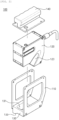
- FIG. 2 is an exploded perspective view of an apparatus for measuring a step difference according to the embodiment
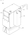
- FIG. 3 is a coupled perspective view of the apparatus for measuring a step difference according to the embodiment.
- FIG. 4 is a coupled cross-sectional view of an apparatus for measuring a step difference according to another embodiment
- FIG. 6A is a top plan view of an apparatus for measuring a step difference according to still another embodiment
- FIG. 6B is a front view of the apparatus for measuring a step difference according to still another embodiment
- FIG. 6C is a side view of the apparatus for measuring a step difference according to still another embodiment.
- An apparatus 100 for measuring a step difference of a slot die includes a laser sensor 120 and a jig 130.
- the laser sensor 120 and the jig 130 are spaced apart from each other.
- a body part 110 may be further provided and accommodate the laser sensor 120 and the jig 130.
- the laser sensor 120 and the jig 130 are fixedly coupled to the body part 110, but the coupling method is not particularly limited.
- the body part 110 is not particularly limited as long as the body part 110 may fix the laser sensor 120 and the jig 130.
- the body part 110 may include two or more plates, and a cross-section of the body part 110 may have a ' ' shape or a ' ' shape.
- FIG. 5 is a perspective view illustrating a state in which an apparatus for measuring a step difference according to another embodiment is in contact with a slot die.
- the laser sensor 120 is provided to face the ends of an ink-discharge-tip-side lip and a shim of a slot die that is a measurement target. Specifically, the laser sensor 120 is provided to face the ends of the lip and the shim of the slot die including two or more bodies 211 and 221 having lips 213 and 223 provided at one end thereof, and a shim 230 provided between the two or more ribs so that ink is discharged.
- the laser sensor 120 may emit laser beams to the ends of the lip and the shim of the slot die, detect the laser beams reflected by surfaces of the lip and the shim of the slot die, and derive a shape of the gap.
- the laser sensor 120 may include a laser emitter (not illustrated) configured to emit laser beams to the ends of the lip and the shim of the slot die, and a detector 123 configured to detect the laser beams reflected by the surfaces of the lip and the shim of the slot die.
- the laser emitter (not illustrated) of the laser sensor 120 is provided to allow the laser beam emitted from a light source to reach the measurement target.
- the laser beam is light having high straightness
- the measurement target is positioned on an extension line in a direction in which the laser beam is emitted.
- the laser beam emitted from the laser sensor 120 is not particularly limited as long as the laser beam is reflected well by the surface, to which the laser beam is emitted, without affecting the material or shape of the ink discharge tip of the slot die.
- the laser beam may be a visible laser beam of 380 nm to 800 nm.
- the laser beam may be a blue laser beam, more specifically, it may be a laser beam of 405 nm.
- the detector 123 of the laser sensor 120 may be a plate-shaped sensor capable of detecting the laser beam reflected by the surfaces of the lip and the shim of the slot die. To allow the reflected laser beam to reach the detector, an angle at which the plate-shaped sensor of the detector 123 is provided may be adjusted and determined in consideration of an emission angle of the laser beam and the shapes of the lip and the shim.
- the laser sensor 120 may include an output part (not illustrated) that derives shapes of the ink-discharge-tip-side lip and the shim of the slot die on the basis of information detected by the detector 123.
- the shape derived by the output part is a vertical cross-section in a longitudinal direction of an ink-discharge-tip-side end. For example, the shape similar to shapes illustrated in FIGS. 7 and 9 is derived. Based on such a shape, a height difference between designated points through coordinates of a step difference measurement point, that is, a stepdifference may be derived.
- the jig 130 is configured to come into contact with at least a part of the body where a portion of the slot die from which the ink is discharged is positioned.
- the jig 130 comes into contact with and supports at least a part of the body to maintain the measurement position and a distance between the laser sensor 120 and the measurement target so that the laser sensor 120 may measure the step difference between the lip and the shim.
- a distance between the lip and the laser sensor may be 17 mm or more and 23 mm or less, or 17.8 mm or more and 22.2 mm or less, i.e., 20 ⁇ 2.2 mm.
- the laser sensor senses the step difference while maintaining a predetermined interval between the laser sensor and the measurement target. The laser sensor cannot sense the step difference in the case that the predetermined interval deviates from a predetermined distance.
- An area in which the jig 130 is in contact with the body is not particularly limited as long as the apparatus 100 for measuring a step difference may be stably positioned.
- the stability may increase as the contact area increases. Therefore, the contact area may be designed to be a maximally large contact area in consideration of an overall size of the apparatus for measuring a step difference.
- the jig 130 may have a shape made by cutting a ' '-shaped cross-section along a gradient of an inclined surface of the body.
- the jig 130 may come into contact with an upper surface of the first or second body 211 or 221 of the single die.
- the jig 130 may come into contact with an upper surface of a first or third body 311 or 331 of the double die.
- the jig 130 may have a shape made by cutting a ' '-shaped cross-section along a gradient of the inclined surface of the body.
- the jig 130 may come into contact with the upper surfaces of the first and second bodies 211 and 221 of the single die.
- the jig 130 may come into contact with the upper surfaces of the first and third bodies 311 and 331 of the double die.
- the surface of the body, where the portion from which the ink is discharged is positioned is an inclined surface having an inclination while defining a predetermined angle with respect to a lateral surface of the lip in consideration of the surface indicated by the arrow indicating the portion with which the jig is in contact as illustrated in FIGS. 7 and 9 . Therefore, to increase the contact area with the jig, a contact portion 133 of the jig may also have an inclination angle identical or similar to the inclination angle of the inclined surface.
- the jig 130 is made of a material selected from materials that do not scratch the body and the lip of the slot die with which the jig 130 is in contact.
- the material of the jig may contain, but not limited to, acetal.
- the jig 130 of the apparatus 100 for measuring a step difference is disposed to be closer to the slot die than the laser sensor 120 so that the jig 130 comes into contact with the body of the slot die. Therefore, the jig 130 has at least one through-hole 131 so that the laser beam emitted from the laser sensor 120 may reach the ink discharge tip of the slot die, and the reflected laser beam may reach the detector.
- the through-hole 131 may be a single hole through which the laser beam may reach the ink discharge tip of the slot die, and the reflected laser beam may reach the detector.
- the through-hole 131 may include a first hole through which the laser beam reaches the ink discharge tip of the slot die, and a second hole through which the reflected laser beam reaches the detector.
- the apparatus for measuring a step difference of a slot die further includes a determination part (not illustrated).
- the determination part compares the step difference between the lip and the shim, which is measured by the laser sensor, with a reference value. In case that the step difference between the lip and the shim, which is measured by the laser sensor, exceeds the reference value, the determination part determines to reassemble the slot die.
- the reference value is an important factor used to determine the amount of coating, the coating pattern, and the like. Whether the designed step difference is maintained is identified. In case that the step difference increases to a value equal to or larger than an allowable value, the slot die may be reassembled or adjusted so that the step difference is maintained within the reference value.
- the reference value may be 300 um.
- the spread of the ink caused by the step difference is constant, and a deviation of a width of the applied slurry is maintained at a predetermined level.
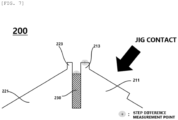
- FIG. 7 is a cross-sectional view of the ink discharge tip of the single die.
- the slot die may be a single die 200.
- the slot die which is the single die 200, includes the first body 211 having the first lip 213, the second body 221 having the second lip 223, and the shim 230 provided between the first body 211 and the second body 221.
- the laser sensor 120 may measure the step difference between the end of the first lip 213 and the end of the shim 230.
- the determination part may compare the step difference between the end of the first lip 213 and the end of the shim 230, which is measured by the laser sensor, with the reference value.
- the reference value may be a step difference targeted at the time of assembling the single die 200.
- the reference value may be 300 um.
- the laser sensor 120 may further measure a step difference between the end of the first lip 213 and the end of the second lip 223.
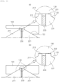
- FIG. 8A is a side view illustrating a state in which the apparatus for measuring a step difference of a slot die according to the embodiment of the present specification is in contact with the single die
- FIG. 8B is a side view illustrating a state in which the apparatus for measuring a step difference of a slot die according to still another embodiment of the present specification is in contact with the single die.
- the shape in which the jig 130 comes into contact with the single die may vary depending on the shape of the jig 130.
- FIG. 9 is a cross-sectional view of an ink discharge tip of a double die.
- the slot die may be a double die 300.
- the slot die which is the double die 300, includes the first body 311 having the first lip 313, the second body 321 having the second lip 323, the third body 331 having the third lip 333, a first shim 340 provided between the first rib 313 and the second rib 323, and a second shim 350 provided between the second rib 323 and the third rib 333.
- the laser sensor 120 may measure a step difference between the end of the first lip 313 and the end of the first shim 340 and a step difference between the end of the second lip 323 and the end of the second shim 350.
- the determination part may compare at least one of the step difference between the end of the first lip 313 and the end of the first shim 340 and the step difference between the end of the second lip 323 and the end of the second shim 350, which are measured by the laser sensor, with the reference value.
- the reference value may be a step difference targeted at the time of assembling the double die 300.
- the reference value related to the step difference between the end of the first lip 313 and the end of the first shim 340 may be 300 um.
- the laser sensor 120 may further measure a step difference between the end of the first lip 313 and the end of the second lip 323 and a step difference between the end of the second lip 323 and the end of the third lip 333.
- FIG. 10A is a side view illustrating a state in which the apparatus for measuring a step difference of a slot die according to the embodiment of the present specification is in contact with the double die
- FIG. 10B is a side view illustrating a state in which the apparatus for measuring a step difference of a slot die according to still another embodiment of the present specification is in contact with the double die.
- the shape in which the jig 130 comes into contact with the single die may vary depending on the shape of the jig 130.
- the apparatus 100 for measuring a step difference of a slot die may further include a handle 140.
- the apparatus 100 for measuring a step difference is a portable apparatus that may be easily carried, moved, and stored by a measurer. Because it is difficult to disassemble and reassemble the slot die once the slot die is installed on the coating apparatus by stacking the bodies and the shim, it is advantageous for the apparatus for measuring the step difference of the slot die to have high portability.
- the handle may be designed such that the measurer may easily carry the apparatus, and the measurer holds the handle by hand while bringing the jig into contact with the slot die at the time of measuring the step difference.
- the apparatus 100 for measuring a step difference may further include a controller (not illustrated) configured to control the laser sensor 120.
- a controller not illustrated
- the components in the apparatus 100 for measuring a step difference i.e., the components required to supply power, perform control, and output data are connected to one another by electric wires.
- the apparatus 100 for measuring a step difference may be simply disassembled, connected, and installed to provide portability.
- the components of the apparatus 100 may be stored in a portable casing after the apparatus 100 is disassembled.
- Still another embodiment of the present specification provides a method of measuring a step difference of a slot die, which includes two or more bodies having lips provided at one end thereof, and a shim provided between the two or more lips and configured to discharge ink, the method including: bringing a jig of the apparatus for measuring a step difference, which has a laser sensor, into contact with at least a part of an upper end of the body where a portion of the slot die from which the ink is discharged is positioned; and measuring, by the laser sensor, a step difference between the lip and the shim of the slot die.
- the description of the method of measuring a step difference of a slot die may be replaced with the description of the apparatus for measuring a step difference.
- the method of measuring a step difference of a slot die may further include comparing the step difference between the lip and the shim, which is measured by the laser sensor, with a reference value.
- the method of measuring a step difference of a slot die may further include reassembling the slot die when the step difference between the lip and the shim, which is measured by the laser sensor, exceeds the reference value.
- the reference value may be 300 um.
- An experimental slot die as illustrated in FIG. 11A was manufactured, and a step difference offset was measured by the apparatus for measuring a step difference.
- the step difference was measured ten times under the conditions set in Table 1, and the evaluation of errors of measured data was collected.
- the "measurer readjustment measurement reproducibility” means reproducibility of data when the measurer is separated from the slot die after the measurement and adjusted in measurement position, and then the measurement is performed.
- the “sensor continuous measurement repeatability” means repeatability of measured data continuously measured without separating the measurer from the slot die after the measurement.
- a master (verification) specimen was a master (verification) specimen of Mitutoyo to which a step difference level was arbitrarily preset. How accurately the data value is measured by the apparatus for measuring a step difference according to the present specification was identified. Master (verification) specimens having step differences of 50 ⁇ m, 100 ⁇ m, and 300 um were used. In this case, the step differences were selected at levels at which the step difference needed to be adjusted to the step difference between the lip and the shim of the die.
- the apparatus for measuring a step difference used lasers with the following conditions.
- a bottom shim offset is a step difference of 1-2
- a bottom die offset is a step difference of 1-3
- a top shim offset is a step difference of 3-4
- a top die offset is a step difference of 3-5.
- 1 to (5) mean positions respectively corresponding to the step difference measurement points indicated by the points illustrated in FIG. 11A .
- FIG. 11B An image of the slot die made by laser sensing of the apparatus for measuring a step difference is illustrated in FIG. 11B .
- the step difference measurement points were designated on the above-mentioned image, and then the offset values were derived.
- Target thickness of verification specimen 50um 100um 300um Item Actually measured thickness (mm) Actually measured thickness (mm) Actually measured thickness (mm) Actually measured thickness (mm) 1 0.051 0.102 0.300 2 0.051 0.102 0.300 3 0.051 0.102 0.300 4 0.05 0.102 0.300 5 0.051 0.102 0.300 6 0.05 0.103 0.300 7 0.05 0.102 0.300 8 0.05 0.102 0.300 9 0.05 0.102 0.300 10 0.05 0.102 0.300 Average 0.050 0.102 0.300 Standard deviation 0.001 0.000 0.000 0.000
- Table 5 A result of measuring the step difference of the experimental die according to the scheme in Table 1 is shown in Table 5, and a result of measuring a target thickness and an actually measured thickness of the verification specimen is shown in Table 6.
- Table 6 Classification Measurement of experimental die Data Measurer readjustment measurement reproducibility Sensor continuous measurement repeatability Average Standard deviation Average Standard deviation Experimental die step difference measurement position Bottom Shim offset 293um 2um 295um 0um Bot-Mid Die Offset 11um 2um 10um 0um Top Shim Offset 665um 12um 643um 1um Mid-Top Die Offset 5um 2um 6um 0um
- Classification Measurement of verification specimen Data Measurer readjustment measurement reproducibility Average Standard deviation Target thickness of Specimen of 50um 50um 1um verification Specimen of 100um 102um 0um specimen Specimen of 300um 300um 0um
- the apparatus for measuring a step difference may measure the step difference (offset) between the lip and the shim of the slot die, and the reproducibility and reliability of the measured numerical value are high.
Landscapes
- Physics & Mathematics (AREA)
- General Physics & Mathematics (AREA)
- Length Measuring Devices By Optical Means (AREA)
- Coating Apparatus (AREA)
Abstract
Description
- This application claims priority to and the benefit of
Korean Patent Application No. 10-2021-0147971 filed with the Korean Intellectual Property Office on November 1, 2021 - The present specification relates to an apparatus and method for measuring a step difference between a lip and a shim of a slot die.
- Recently, prices of energy sources have been raised because of the depletion of fossil fuels, and the interest in environmental pollution is increasing. Therefore, there is an increasing demand for environmental-friendly alternative energy sources. Therefore, research on various power production technologies such as nuclear power, solar power, wind power, and tidal power is continuously being conducted. In addition, interest in power storage devices for more efficiently using the produced energy is high.
- In particular, as the development of technologies and demands for mobile devices are increased, there is a rapidly increasing demand for batteries as energy sources. Many studies are being conducted on the batteries in order to meet these needs.
- Representatively, regarding a shape of the battery, there is a high demand for an angular or pouch-type secondary battery that may have a small thickness and be applied to products such as mobile phones. Regarding a material, there is a high demand for lithium secondary batteries such as lithium-ion batteries or lithium-ion polymer batteries that have advantages such as a high energy density, a discharge voltage, and output stability.
- In general, the secondary battery is structured to include an electrode assembly made by stacking a positive electrode, a negative electrode, and a separator positioned between the positive electrode and the negative electrode. The positive and negative electrodes are each manufactured by applying slurry containing an active material onto a current collector.
- The current collector needs to be coated with the slurry having a uniform thickness to uniformize characteristics of the secondary batteries. To this end, a slurry coating apparatus such as a die coater is used. The slurry coating apparatus includes a slot die for thinly applying the slurry over a wide area.
- The coating method using the slot die is better in terms of maintenance and productivity than other coating methods. Therefore, the coating method using the slot die is widely and presently used for a process of manufacturing a panel for a flat panel display device as well as the process of applying slurry onto the current collector of the secondary battery electrode.
- Like a fountain pen in which ink is discharged through a nib, the slot die discharges slurry through a tip thereof for discharging ink, such that the slurry is applied onto the current collector while the slot die itself moves or the current collector is moved.
- There is a step difference (shim offset or gap) between a lip and a shim at two opposite ends of the slot die based on a width direction of the current collector. The ink is spread by surface tension in the step difference during the coating process using the slot die.
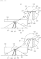
- In this case, when the step difference between the lip and the shim is a predetermined level or lower, the spread occurs uniformly, and thus a deviation of a width of the applied slurry is small. However, in case that the step difference between the lip and the shim deviates from the predetermined level as illustrated in
FIG. 1 , the deviation of the width of the applied slurry increases. - Accordingly, the management needs to be performed to prevent the step difference between the lip and the shim from deviating from the predetermined level. To this end, it is necessary to devise a method capable of measuring the step difference between the lip and the shim.
- The present specification provides an apparatus and method for measuring a step difference between a lip and a shim of a slot die.
- An embodiment of the present specification provides an apparatus for measuring a step difference of a slot die, the apparatus including: a laser sensor configured to measure a step difference between a lip and a shim of a slot die including two or more bodies having the lips provided at one end thereof, and the shim provided between the two or more lips and configured to discharge ink, the laser sensor being disposed to face the lip and the shim of the slot die; and a jig configured to come into contact with at least a part of the body where a portion of the slot die from which the ink is discharged is positioned.
- Another embodiment of the present specification provides a method of measuring a step difference of a slot die, which includes two or more bodies having lips provided at one end thereof, and a shim provided between the two or more lips and configured to discharge ink, the method including: bringing a jig of the apparatus, which has a laser sensor, into contact with at least a part of an upper end of the body where a portion of the slot die from which the ink is discharged is positioned; and measuring, by the laser sensor, a step difference between the lip and the shim of the slot die.
- The apparatus for measuring a step difference of a slot die according to the embodiment of the present specification may measure the step difference between the lip and the shim.
- The apparatus for measuring a step difference of a slot die according to another embodiment of the present specification may determine the measured step difference between the lip and the shim, which makes it possible to manage the step difference at the appropriate level.
- The apparatus for measuring a step difference of a slot die according to still another embodiment of the present specification has high portability. Therefore, the apparatus may measure the step difference between the lip and the shim after performing ink coating, which makes it possible to often check a change in step difference according to the process.
- The apparatus for measuring a step difference of a slot die according to yet another embodiment of the present specification may check a change of the step difference according to the ink coating process and adjust the step difference between the lip and the shim when the change of the step difference is severe.
-
-
FIG. 1 is a view illustrating a problem of nonuniformity of a coating interface that occurs when a step difference between a lip and a shim of a slot die is large. -
FIG. 2 is an exploded perspective view of an apparatus for measuring a step difference according to the embodiment. -
FIG. 3 is a coupled perspective view of the apparatus for measuring a step difference according to the embodiment. -
FIG. 4 is a coupled cross-sectional view of an apparatus for measuring a step difference according to another embodiment. -
FIG. 5 is a perspective view illustrating a state in which an apparatus for measuring a step difference according to another embodiment is in contact with a slot die. -
FIG. 6A is a top plan view of an apparatus for measuring a step difference according to still another embodiment,FIG. 6B is a front view of the apparatus for measuring a step difference according to still another embodiment, andFIG. 6C is a side view of the apparatus for measuring a step difference according to still another embodiment. -
FIG. 7 is a cross-sectional view of an ink discharge tip of a single die. -
FIG. 8A is a side view illustrating a state in which the apparatus for measuring a step difference of a slot die according to the embodiment of the present specification is in contact with the single die, andFIG. 8B is a side view illustrating a state in which the apparatus for measuring a step difference of a slot die according to still another embodiment of the present specification is in contact with the single die. -
FIG. 9 is a cross-sectional view of an ink discharge tip of a double die. -
FIG. 10A is a side view illustrating a state in which the apparatus for measuring a step difference of a slot die according to the embodiment of the present specification is in contact with the double die, andFIG. 10B is a side view illustrating a state in which the apparatus for measuring a step difference of a slot die according to still another embodiment of the present specification is in contact with the double die. -
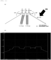
FIG. 11A is a cross-sectional view of an experimental slot die manufactured according to the embodiment, andFIG. 11B is an image of a slot die made by laser sensing of the apparatus for measuring a step difference. -
- 100:
- Apparatus for measuring step difference
- 110:
- Body part
- 120:
- Laser sensor
- 123:
- Detector
- 130:
- Jig
- 131:
- Through-hole
- 133:
- Contact portion
- 140:
- Handle
- 200:
- Single die
- 211:
- First body
- 213:
- First lip
- 221:
- Second body
- 223:
- Second lip
- 230:
- Shim
- 300:
- Double die
- 311:
- First body
- 313:
- First lip
- 321:
- Second body
- 323:
- Second lip
- 331:
- Third body
- 333:
- Third lip
- 340:
- First shim
- 350:
- Second shim
- Hereinafter, the present disclosure will be described in detail with reference to the drawings. However, the drawings are intended to illustratively describe the present disclosure, and the scope of the present disclosure is not limited by the drawings.
-
FIG. 2 is an exploded perspective view of an apparatus for measuring a step difference according to the embodiment, andFIG. 3 is a coupled perspective view of the apparatus for measuring a step difference according to the embodiment. -
FIG. 4 is a coupled cross-sectional view of an apparatus for measuring a step difference according to another embodiment,FIG. 6A is a top plan view of an apparatus for measuring a step difference according to still another embodiment,FIG. 6B is a front view of the apparatus for measuring a step difference according to still another embodiment, andFIG. 6C is a side view of the apparatus for measuring a step difference according to still another embodiment. - An
apparatus 100 for measuring a step difference of a slot die includes alaser sensor 120 and ajig 130. In this case, thelaser sensor 120 and thejig 130 are spaced apart from each other. Abody part 110 may be further provided and accommodate thelaser sensor 120 and thejig 130. Thelaser sensor 120 and thejig 130 are fixedly coupled to thebody part 110, but the coupling method is not particularly limited. Thebody part 110 is not particularly limited as long as thebody part 110 may fix thelaser sensor 120 and thejig 130. Thebody part 110 may include two or more plates, and a cross-section of thebody part 110 may have a '' shape or a ' ' shape.
-
FIG. 5 is a perspective view illustrating a state in which an apparatus for measuring a step difference according to another embodiment is in contact with a slot die. - The
laser sensor 120 is provided to face the ends of an ink-discharge-tip-side lip and a shim of a slot die that is a measurement target. Specifically, thelaser sensor 120 is provided to face the ends of the lip and the shim of the slot die including two ormore bodies lips shim 230 provided between the two or more ribs so that ink is discharged. - The
laser sensor 120 may emit laser beams to the ends of the lip and the shim of the slot die, detect the laser beams reflected by surfaces of the lip and the shim of the slot die, and derive a shape of the gap. - The
laser sensor 120 may include a laser emitter (not illustrated) configured to emit laser beams to the ends of the lip and the shim of the slot die, and adetector 123 configured to detect the laser beams reflected by the surfaces of the lip and the shim of the slot die. - The laser emitter (not illustrated) of the
laser sensor 120 is provided to allow the laser beam emitted from a light source to reach the measurement target. In this case, the laser beam is light having high straightness, and the measurement target is positioned on an extension line in a direction in which the laser beam is emitted. - The laser beam emitted from the
laser sensor 120 is not particularly limited as long as the laser beam is reflected well by the surface, to which the laser beam is emitted, without affecting the material or shape of the ink discharge tip of the slot die. For example, the laser beam may be a visible laser beam of 380 nm to 800 nm. Specifically, the laser beam may be a blue laser beam, more specifically, it may be a laser beam of 405 nm. - The
detector 123 of thelaser sensor 120 may be a plate-shaped sensor capable of detecting the laser beam reflected by the surfaces of the lip and the shim of the slot die. To allow the reflected laser beam to reach the detector, an angle at which the plate-shaped sensor of thedetector 123 is provided may be adjusted and determined in consideration of an emission angle of the laser beam and the shapes of the lip and the shim. - The
laser sensor 120 may include an output part (not illustrated) that derives shapes of the ink-discharge-tip-side lip and the shim of the slot die on the basis of information detected by thedetector 123. The shape derived by the output part is a vertical cross-section in a longitudinal direction of an ink-discharge-tip-side end. For example, the shape similar to shapes illustrated inFIGS. 7 and9 is derived. Based on such a shape, a height difference between designated points through coordinates of a step difference measurement point, that is, a stepdifference may be derived. - The
jig 130 is configured to come into contact with at least a part of the body where a portion of the slot die from which the ink is discharged is positioned. Thejig 130 comes into contact with and supports at least a part of the body to maintain the measurement position and a distance between thelaser sensor 120 and the measurement target so that thelaser sensor 120 may measure the step difference between the lip and the shim. - A distance between the lip and the laser sensor may be 17 mm or more and 23 mm or less, or 17.8 mm or more and 22.2 mm or less, i.e., 20 ± 2.2 mm. The laser sensor senses the step difference while maintaining a predetermined interval between the laser sensor and the measurement target. The laser sensor cannot sense the step difference in the case that the predetermined interval deviates from a predetermined distance.
- An area in which the
jig 130 is in contact with the body is not particularly limited as long as theapparatus 100 for measuring a step difference may be stably positioned. The stability may increase as the contact area increases. Therefore, the contact area may be designed to be a maximally large contact area in consideration of an overall size of the apparatus for measuring a step difference. - As illustrated in
FIGS. 8A and10A , thejig 130 may have a shape made by cutting a ''-shaped cross-section along a gradient of an inclined surface of the body. In case that the step difference measurement target is a single die, the
jig 130 may come into contact with an upper surface of the first orsecond body jig 130 may come into contact with an upper surface of a first orthird body - As illustrated in
FIGS. 8B and10B , thejig 130 may have a shape made by cutting a ''-shaped cross-section along a gradient of the inclined surface of the body. In case that the step difference measurement target is the single die, the
jig 130 may come into contact with the upper surfaces of the first andsecond bodies jig 130 may come into contact with the upper surfaces of the first andthird bodies - Referring to
FIGS. 7 and9 , the surface of the body, where the portion from which the ink is discharged is positioned, is an inclined surface having an inclination while defining a predetermined angle with respect to a lateral surface of the lip in consideration of the surface indicated by the arrow indicating the portion with which the jig is in contact as illustrated inFIGS. 7 and9 . Therefore, to increase the contact area with the jig, acontact portion 133 of the jig may also have an inclination angle identical or similar to the inclination angle of the inclined surface. - Because the
jig 130 is a part that comes into contact with the body and the lip of the slot die, thejig 130 is made of a material selected from materials that do not scratch the body and the lip of the slot die with which thejig 130 is in contact. For example, the material of the jig may contain, but not limited to, acetal. - The
jig 130 of theapparatus 100 for measuring a step difference is disposed to be closer to the slot die than thelaser sensor 120 so that thejig 130 comes into contact with the body of the slot die. Therefore, thejig 130 has at least one through-hole 131 so that the laser beam emitted from thelaser sensor 120 may reach the ink discharge tip of the slot die, and the reflected laser beam may reach the detector. - The through-
hole 131 may be a single hole through which the laser beam may reach the ink discharge tip of the slot die, and the reflected laser beam may reach the detector. - The through-
hole 131 may include a first hole through which the laser beam reaches the ink discharge tip of the slot die, and a second hole through which the reflected laser beam reaches the detector. - The apparatus for measuring a step difference of a slot die according to the embodiment of the present specification further includes a determination part (not illustrated).
- The determination part compares the step difference between the lip and the shim, which is measured by the laser sensor, with a reference value. In case that the step difference between the lip and the shim, which is measured by the laser sensor, exceeds the reference value, the determination part determines to reassemble the slot die. The reference value is an important factor used to determine the amount of coating, the coating pattern, and the like. Whether the designed step difference is maintained is identified. In case that the step difference increases to a value equal to or larger than an allowable value, the slot die may be reassembled or adjusted so that the step difference is maintained within the reference value.
- The reference value may be 300 um. In case that the step difference between the lip and the shim is equal to or smaller than 300 µm, the spread of the ink caused by the step difference is constant, and a deviation of a width of the applied slurry is maintained at a predetermined level.
-
FIG. 7 is a cross-sectional view of the ink discharge tip of the single die. - The slot die may be a
single die 200. The slot die, which is thesingle die 200, includes thefirst body 211 having thefirst lip 213, thesecond body 221 having thesecond lip 223, and theshim 230 provided between thefirst body 211 and thesecond body 221. - The
laser sensor 120 may measure the step difference between the end of thefirst lip 213 and the end of theshim 230. The determination part may compare the step difference between the end of thefirst lip 213 and the end of theshim 230, which is measured by the laser sensor, with the reference value. In this case, the reference value may be a step difference targeted at the time of assembling thesingle die 200. For example, the reference value may be 300 um. - In addition, the
laser sensor 120 may further measure a step difference between the end of thefirst lip 213 and the end of thesecond lip 223. -
FIG. 8A is a side view illustrating a state in which the apparatus for measuring a step difference of a slot die according to the embodiment of the present specification is in contact with the single die, andFIG. 8B is a side view illustrating a state in which the apparatus for measuring a step difference of a slot die according to still another embodiment of the present specification is in contact with the single die. As illustrated inFIGS. 8A and 8B , the shape in which thejig 130 comes into contact with the single die may vary depending on the shape of thejig 130. -
FIG. 9 is a cross-sectional view of an ink discharge tip of a double die. - The slot die may be a
double die 300. The slot die, which is thedouble die 300, includes thefirst body 311 having thefirst lip 313, thesecond body 321 having thesecond lip 323, thethird body 331 having thethird lip 333, afirst shim 340 provided between thefirst rib 313 and thesecond rib 323, and asecond shim 350 provided between thesecond rib 323 and thethird rib 333. - The
laser sensor 120 may measure a step difference between the end of thefirst lip 313 and the end of thefirst shim 340 and a step difference between the end of thesecond lip 323 and the end of thesecond shim 350. The determination part may compare at least one of the step difference between the end of thefirst lip 313 and the end of thefirst shim 340 and the step difference between the end of thesecond lip 323 and the end of thesecond shim 350, which are measured by the laser sensor, with the reference value. In this case, the reference value may be a step difference targeted at the time of assembling thedouble die 300. For example, the reference value related to the step difference between the end of thefirst lip 313 and the end of thefirst shim 340 may be 300 um. - In addition, the
laser sensor 120 may further measure a step difference between the end of thefirst lip 313 and the end of thesecond lip 323 and a step difference between the end of thesecond lip 323 and the end of thethird lip 333. -
FIG. 10A is a side view illustrating a state in which the apparatus for measuring a step difference of a slot die according to the embodiment of the present specification is in contact with the double die, andFIG. 10B is a side view illustrating a state in which the apparatus for measuring a step difference of a slot die according to still another embodiment of the present specification is in contact with the double die. As illustrated inFIGS. 10A and 10B , the shape in which thejig 130 comes into contact with the single die may vary depending on the shape of thejig 130. - The
apparatus 100 for measuring a step difference of a slot die according to the embodiment of the present specification may further include ahandle 140. - The
apparatus 100 for measuring a step difference is a portable apparatus that may be easily carried, moved, and stored by a measurer. Because it is difficult to disassemble and reassemble the slot die once the slot die is installed on the coating apparatus by stacking the bodies and the shim, it is advantageous for the apparatus for measuring the step difference of the slot die to have high portability. - The handle may be designed such that the measurer may easily carry the apparatus, and the measurer holds the handle by hand while bringing the jig into contact with the slot die at the time of measuring the step difference.
- The
apparatus 100 for measuring a step difference may further include a controller (not illustrated) configured to control thelaser sensor 120. As necessary, the components in theapparatus 100 for measuring a step difference, i.e., the components required to supply power, perform control, and output data are connected to one another by electric wires. In addition, theapparatus 100 for measuring a step difference may be simply disassembled, connected, and installed to provide portability. The components of theapparatus 100 may be stored in a portable casing after theapparatus 100 is disassembled. - Still another embodiment of the present specification provides a method of measuring a step difference of a slot die, which includes two or more bodies having lips provided at one end thereof, and a shim provided between the two or more lips and configured to discharge ink, the method including: bringing a jig of the apparatus for measuring a step difference, which has a laser sensor, into contact with at least a part of an upper end of the body where a portion of the slot die from which the ink is discharged is positioned; and measuring, by the laser sensor, a step difference between the lip and the shim of the slot die.
- In this case, to prevent the repeated description, the description of the method of measuring a step difference of a slot die may be replaced with the description of the apparatus for measuring a step difference.
- The method of measuring a step difference of a slot die may further include comparing the step difference between the lip and the shim, which is measured by the laser sensor, with a reference value.
- The method of measuring a step difference of a slot die may further include reassembling the slot die when the step difference between the lip and the shim, which is measured by the laser sensor, exceeds the reference value. In this case, the reference value may be 300 um.
- Hereinafter, the present specification will be described in more detail with reference to examples. However, the flowing examples are intended to illustratively describe the present specification, and the scope of the present specification is not limited by the flowing examples.
- An experimental slot die as illustrated in
FIG. 11A was manufactured, and a step difference offset was measured by the apparatus for measuring a step difference. The step difference was measured ten times under the conditions set in Table 1, and the evaluation of errors of measured data was collected. In this case, the "measurer readjustment measurement reproducibility" means reproducibility of data when the measurer is separated from the slot die after the measurement and adjusted in measurement position, and then the measurement is performed. The "sensor continuous measurement repeatability" means repeatability of measured data continuously measured without separating the measurer from the slot die after the measurement. - A master (verification) specimen was a master (verification) specimen of Mitutoyo to which a step difference level was arbitrarily preset. How accurately the data value is measured by the apparatus for measuring a step difference according to the present specification was identified. Master (verification) specimens having step differences of 50 µm, 100 µm, and 300 um were used. In this case, the step differences were selected at levels at which the step difference needed to be adjusted to the step difference between the lip and the shim of the die.
[Table 1] Classification Measurer readjustment measurement reproducibility Sensor continuous measurement repeatability Data Measurement of experimental die Measurement of verification specimen Measurement of mini-die Measurement direction Readjustment of measurer → repeated measurement of specimen After fixing of sensor to specimen → repeated measurement of only sensor Number of data 10ea 10ea 10ea Remarks - Measurement of verification specimen for each thickness(5 0/100/3 00um) - In this case, the apparatus for measuring a step difference used lasers with the following conditions.
- Reference distance (Z-axis): 20±2.2 mm (repetition degree of 0.3 µm)
- Measuring range (X-axis): 7.5 mm (repetition degree of 0.3 µm)
- Data interval: 2.5 um
- Light source: blue LED (blue semiconductor laser)
- Wavelength: 405 nm visible ray
- Output: 10 mV
- A result of measuring the step difference of the experimental die each time the readjustment of the measurement position of the measurer, i.e., the apparatus for measuring a step difference was performed according to the scheme in Table 1, is shown in Table 2 below.
[Table 2] No Out 1Out 2 Out 3 Out 4 Item Bottom Shim offset (mm) Bottom Die Offset (mm) Top Shim Offset (mm) Top Die Offset (mm) 1 0.295 0.013 0.691 0.008 2 0.293 0.008 0.675 0.008 3 0.291 0.011 0.654 0.004 4 0.294 0.013 0.653 0.005 5 0.293 0.011 0.663 0.003 6 0.292 0.01 0.668 0.005 7 0.291 0.01 0.66 0.004 8 0.292 0.01 0.657 0.003 9 0.295 0.011 0.677 0.005 10 0.291 0.008 0.656 0.001 Average 0.293 0.011 0.665 0.005 Standard deviation 0.002 0.002 0.012 0.002 - Based on
FIG. 11A , a bottom shim offset is a step difference of ①-②, a bottom die offset is a step difference of ①-③, a top shim offset is a step difference of ③-④, and a top die offset is a step difference of ③-⑤. In this case, ① to (5) mean positions respectively corresponding to the step difference measurement points indicated by the points illustrated inFIG. 11A . - An image of the slot die made by laser sensing of the apparatus for measuring a step difference is illustrated in
FIG. 11B . The step difference measurement points were designated on the above-mentioned image, and then the offset values were derived. - A result of measuring the thickness of the verification specimen each time the readjustment of the measurement positions of the measurer, i.e., the apparatus for measuring a step difference, and the verification specimen was performed according to the scheme in Table 1 is shown in Table 3 below.
[Table 3] Target thickness of verification specimen 50um 100um 300um Item Actually measured thickness (mm) Actually measured thickness (mm) Actually measured thickness (mm) 1 0.051 0.102 0.300 2 0.051 0.102 0.300 3 0.051 0.102 0.300 4 0.05 0.102 0.300 5 0.051 0.102 0.300 6 0.05 0.103 0.300 7 0.05 0.102 0.300 8 0.05 0.102 0.300 9 0.05 0.102 0.300 10 0.05 0.102 0.300 Average 0.050 0.102 0.300 Standard deviation 0.001 0.000 0.000 - A result of fixing the measurer and continuously sensing the step difference of the experimental die according to the scheme in Table 1 is shown in Table 4 below.
[Table 4] No Out 1Out 2 Out 3 Out 4 Item Bottom Shim offset (mm) Bottom Die Offset (mm) Top Shim Offset (mm) Top Die Offset (mm) 1 0.295 0.01 0.645 0.006 2 0.295 0.01 0.645 0.006 3 0.295 0.01 0.641 0.006 4 0.295 0.01 0.641 0.006 5 0.295 0.01 0.643 0.006 6 0.295 0.01 0.643 0.006 7 0.295 0.01 0.643 0.006 8 0.295 0.01 0.643 0.006 9 0.295 0.01 0.643 0.006 10 0.295 0.009 0.645 0.006 Average 0.295 0.010 0.643 0.006 Standard deviation 0.000 0.000 0.001 0.000 - A result of measuring the step difference of the experimental die according to the scheme in Table 1 is shown in Table 5, and a result of measuring a target thickness and an actually measured thickness of the verification specimen is shown in Table 6.
[Table 5] Classification Measurement of experimental die Data Measurer readjustment measurement reproducibility Sensor continuous measurement repeatability Average Standard deviation Average Standard deviation Experimental die step difference measurement position Bottom Shim offset 293um 2um 295um 0um Bot-Mid Die Offset 11um 2um 10um 0um Top Shim Offset 665um 12um 643um 1um Mid-Top Die Offset 5um 2um 6um 0um [Table 6] Classification Measurement of verification specimen Data Measurer readjustment measurement reproducibility Average Standard deviation Target thickness of Specimen of 50um 50um 1um verification Specimen of 100um 102um 0um specimen Specimen of 300um 300um 0um - It can be ascertained from Tables 2 to 6 that the apparatus for measuring a step difference according to the present specification may measure the step difference (offset) between the lip and the shim of the slot die, and the reproducibility and reliability of the measured numerical value are high.
Claims (14)
- An apparatus for measuring a step difference of a slot die, the apparatus comprising:a laser sensor configured to measure the step difference between a plurality of lips and an at least one shim of the slot die, wherein the slot die includes a plurality of bodies having the plurality of lips provided at one end thereof, wherein the at least one shim is provided between the plurality of ribs and is configured to discharge an ink, and wherein the laser sensor is disposed to face the plurality of lips and the at least one shim of the slot die; anda jig configured to contact an at least one of the plurality of bodies where a portion of the slot die from which the ink is discharged is positioned.
- The apparatus of claim 1, further comprising:
a determination part configured to compare the step difference between the plurality of lips and the at least one shim with a reference value. - The apparatus of claim 2, wherein the determination part is configured to determine to reassemble the slot die when the step difference between the plurality of lips and the at least one shim exceeds the reference value.
- The apparatus of claim 2, wherein the reference value is 300 um.
- The apparatus of claim 1, wherein the slot die comprises:a first body having a first lip;a second body having a second lip; anda first shim provided between the first body and the second body, andwherein the laser sensor is configured to measure a step difference between an end of the first lip and an end of the first shim.
- The apparatus of claim 5, wherein the laser sensor is configured to measure a step difference between the end of the first lip and an end of the second lip.
- The apparatus of claim 1, wherein the slot die comprises:a first body having a first lip;a second body having a second lip;a third body having a third lip;a first shim provided between the first body and the second body; anda second shim provided between the second body and the third body, andwherein the laser sensor is configured to measure a step difference between an end of the first lip and an end of the first shim and a step difference between an end of the second lip and an end of the second shim.
- The apparatus of claim 7, wherein the laser sensor is configured to measure a step difference between the end of the first lip and the end of the second lip and a step difference between the end of the second lip and an end of the third lip.
- The apparatus of claim 1, wherein a distance between the plurality of lips and the laser sensor is in a range of 17 mm to 23 mm.
- The apparatus of claim 1, wherein the apparatus is a portable apparatus.
- A method of measuring a step difference of a slot die, which includes a plurality of bodies having a plurality of lips provided at one end thereof, and a shim provided between the plurality of lips and is configured to discharge an ink, the method comprising:contacting a jig with at least one of the plurality of bodies where a portion of the slot die from which the ink is discharged is positioned, wherein the jig has a laser sensor; andmeasuring a step difference between the plurality of lips and the at least one shim of the slot die with the laser sensor.
- The method of claim 11, further comprising:
comparing the step difference between the plurality of lips and the at least one shim with a reference value. - The method of claim 12, further comprising:
determining to reassemble the slot die when the step difference between the plurality of lips and the at least one shim exceeds the reference value. - The method of claim 12, wherein the reference value is 300 um.
Applications Claiming Priority (2)
| Application Number | Priority Date | Filing Date | Title |
|---|---|---|---|
| KR1020210147971A KR20230063097A (en) | 2021-11-01 | 2021-11-01 | Apparatus and method for measuring gap of slot die |
| PCT/KR2022/016937 WO2023075572A1 (en) | 2021-11-01 | 2022-11-01 | Step-height measurement device and method for slot die |
Publications (3)
| Publication Number | Publication Date |
|---|---|
| EP4269937A1 true EP4269937A1 (en) | 2023-11-01 |
| EP4269937A4 EP4269937A4 (en) | 2024-02-28 |
| EP4269937B1 EP4269937B1 (en) | 2025-09-24 |
Family
ID=86158357
Family Applications (1)
| Application Number | Title | Priority Date | Filing Date |
|---|---|---|---|
| EP22887766.8A Active EP4269937B1 (en) | 2021-11-01 | 2022-11-01 | Step-height measurement device and method for slot die |
Country Status (8)
| Country | Link |
|---|---|
| US (2) | US12472529B2 (en) |
| EP (1) | EP4269937B1 (en) |
| JP (1) | JP7714659B2 (en) |
| KR (1) | KR20230063097A (en) |
| CN (1) | CN116583711A (en) |
| ES (1) | ES3045365T3 (en) |
| HU (1) | HUE073357T2 (en) |
| WO (1) | WO2023075572A1 (en) |
Families Citing this family (1)
| Publication number | Priority date | Publication date | Assignee | Title |
|---|---|---|---|---|
| KR20250079313A (en) | 2023-11-27 | 2025-06-04 | 주식회사 엘지에너지솔루션 | Simultaneous allignment and measuring module for slot die shim inatallation |
Family Cites Families (21)
| Publication number | Priority date | Publication date | Assignee | Title |
|---|---|---|---|---|
| JPH09248513A (en) | 1996-03-18 | 1997-09-22 | Chugai Ro Co Ltd | Die coater for multiple layers |
| JP3918106B2 (en) | 1999-12-20 | 2007-05-23 | 富士フイルム株式会社 | Coating device |
| JP2002018340A (en) | 2000-07-11 | 2002-01-22 | Fuji Photo Film Co Ltd | Extrusive coating method and device |
| US20030157252A1 (en) * | 2002-01-09 | 2003-08-21 | Yasuhiko Tokimasa | Apparatus and method for applying coating solution, die and method for assembling thereof |
| JP3899485B2 (en) * | 2002-03-22 | 2007-03-28 | 富士フイルム株式会社 | Application method and apparatus |
| US8178166B2 (en) | 2002-01-09 | 2012-05-15 | Fujifilm Corporation | Apparatus and method for applying coating solution, die and method for assembling thereof |
| JP2003245595A (en) | 2002-02-22 | 2003-09-02 | Fuji Photo Film Co Ltd | Coating method |
| CN100474289C (en) * | 2003-09-19 | 2009-04-01 | 欧姆龙株式会社 | Connected sensor system |
| JP2005221305A (en) * | 2004-02-04 | 2005-08-18 | Mitsubishi Materials Corp | Slot die measuring device |
| JP4763325B2 (en) * | 2005-03-30 | 2011-08-31 | 富士フイルム株式会社 | Coating liquid coating method, coating liquid coating apparatus, and optical film manufacturing method |
| JP2007212363A (en) * | 2006-02-10 | 2007-08-23 | Seiko Epson Corp | Liquid repellent area measuring method and liquid repellent area measuring apparatus |
| US8123511B2 (en) | 2007-05-03 | 2012-02-28 | Cloeren Incorporated | Decoupled transverse flow metering gap and lip gap |
| US8092207B2 (en) | 2007-05-03 | 2012-01-10 | Cloeren Incorporated | Decoupled transverse flow metering gap and lip gap |
| JP6030078B2 (en) | 2014-01-23 | 2016-11-24 | 富士フイルム株式会社 | Method for producing coated film |
| KR101578765B1 (en) | 2015-09-24 | 2015-12-18 | 성안기계 주식회사 | Slot die coating apparatus and method for controlling the same |
| KR102301210B1 (en) * | 2017-10-30 | 2021-09-10 | 주식회사 엘지에너지솔루션 | Slot die for coating |
| JP7194152B2 (en) | 2019-09-10 | 2022-12-21 | 東レエンジニアリング株式会社 | Applicator, applicator, and applicator method |
| KR102866099B1 (en) | 2019-11-20 | 2025-09-26 | 삼성에스디아이 주식회사 | Rechargeable battery electrode manufacturing slot die |
| JP7404063B2 (en) * | 2019-12-24 | 2023-12-25 | 株式会社ヒラノテクシード | Blade edge adjustment device, coating device, blade edge adjustment method for coating device |
| KR20210147971A (en) | 2020-05-28 | 2021-12-07 | 부산대학교 산학협력단 | Recombinant Phage-Based Culture Container For Stem Cell Culture and Uses Thereof |
| CN212512923U (en) * | 2020-07-10 | 2021-02-09 | 无锡必力福系统电气有限公司 | Bolt rivet shape inspection device |
-
2021
- 2021-11-01 KR KR1020210147971A patent/KR20230063097A/en active Pending
-
2022
- 2022-11-01 US US18/270,330 patent/US12472529B2/en active Active
- 2022-11-01 JP JP2023540935A patent/JP7714659B2/en active Active
- 2022-11-01 EP EP22887766.8A patent/EP4269937B1/en active Active
- 2022-11-01 WO PCT/KR2022/016937 patent/WO2023075572A1/en not_active Ceased
- 2022-11-01 CN CN202280008116.2A patent/CN116583711A/en active Pending
- 2022-11-01 ES ES22887766T patent/ES3045365T3/en active Active
- 2022-11-01 HU HUE22887766A patent/HUE073357T2/en unknown
-
2025
- 2025-10-22 US US19/365,965 patent/US20260084176A1/en active Pending
Also Published As
| Publication number | Publication date |
|---|---|
| ES3045365T3 (en) | 2025-11-28 |
| HUE073357T2 (en) | 2026-01-28 |
| WO2023075572A1 (en) | 2023-05-04 |
| JP7714659B2 (en) | 2025-07-29 |
| CN116583711A (en) | 2023-08-11 |
| US12472529B2 (en) | 2025-11-18 |
| KR20230063097A (en) | 2023-05-09 |
| JP2024501775A (en) | 2024-01-15 |
| EP4269937A4 (en) | 2024-02-28 |
| US20240109097A1 (en) | 2024-04-04 |
| US20260084176A1 (en) | 2026-03-26 |
| EP4269937B1 (en) | 2025-09-24 |
Similar Documents
| Publication | Publication Date | Title |
|---|---|---|
| US20260084176A1 (en) | Step-Height Measurement Device And Method For Slot Die | |
| US20240072397A1 (en) | Embedded Sensors for In-Situ Cell Monitoring of Batteries | |
| KR101387840B1 (en) | Method of detecting the width of a coated film and detection device used in said detection method | |
| KR102798485B1 (en) | Management method of electrode sliding area | |
| CN115728180A (en) | A method for production detection of lithium battery electrodes | |
| KR102837050B1 (en) | Die Coater Inspecting Apparatus | |
| CN115335157B (en) | Die coating machine and its inspection device | |
| KR102645685B1 (en) | Die Coater And The Apparatus For Inspecting Thereof | |
| KR101778673B1 (en) | A Inspection Device for Battery Packs with Various Length and Thickness | |
| CN1073270C (en) | Assembling equipment and method of electron gun | |
| US12551921B2 (en) | Die coater inspection device and method | |
| Khat et al. | Terahertz Assessment of the Battery Electrodes Save Production Costs of Electric Vehicles | |
| KR20230165642A (en) | Method and apparatus for measuring horizontality of welding-equipment | |
| KR102786780B1 (en) | Dryness measuring device of Secondary battery electrode and Secondary battery electrode manufacturing system having the same | |
| US20250273792A1 (en) | Battery Manufacturing Apparatus and Battery Manufacturing Method Using the Same | |
| CN224147343U (en) | Material testing equipment | |
| KR102732889B1 (en) | Thickness measurement system and thickness measurement method using thereof | |
| US20250216191A1 (en) | Apparatus and method for measuring electrode plate thickness | |
| KR20240104580A (en) | Slot die coating device | |
| KR20250059747A (en) | Method and apparatus for measuring processing precision of electric vehicle battery module mounting part | |
| CN121548911A (en) | Electrode tab guide device | |
| WO2023157058A1 (en) | Electrophoresis device | |
| KR20250008265A (en) | Apparatus and method for measuring curved cell curvature using a laser sensor | |
| KR20250169858A (en) | Device for measuring gap using polarization camera-based laser | |
| KR20250042115A (en) | Inspection device and inspection method of electrode tab |
Legal Events
| Date | Code | Title | Description |
|---|---|---|---|
| STAA | Information on the status of an ep patent application or granted ep patent |
Free format text: STATUS: THE INTERNATIONAL PUBLICATION HAS BEEN MADE |
|
| PUAI | Public reference made under article 153(3) epc to a published international application that has entered the european phase |
Free format text: ORIGINAL CODE: 0009012 |
|
| STAA | Information on the status of an ep patent application or granted ep patent |
Free format text: STATUS: REQUEST FOR EXAMINATION WAS MADE |
|
| 17P | Request for examination filed |
Effective date: 20230726 |
|
| AK | Designated contracting states |
Kind code of ref document: A1 Designated state(s): AL AT BE BG CH CY CZ DE DK EE ES FI FR GB GR HR HU IE IS IT LI LT LU LV MC ME MK MT NL NO PL PT RO RS SE SI SK SM TR |
|
| REG | Reference to a national code |
Ref country code: DE Ref country code: DE Ref legal event code: R079 Ref document number: 602022022096 Country of ref document: DE Free format text: PREVIOUS MAIN CLASS: G01B0011220000 Ipc: G01B0011060000 |
|
| A4 | Supplementary search report drawn up and despatched |
Effective date: 20240131 |
|
| RIC1 | Information provided on ipc code assigned before grant |
Ipc: B05C 5/02 20060101ALI20240125BHEP Ipc: G01B 11/22 20060101ALI20240125BHEP Ipc: G01B 11/06 20060101AFI20240125BHEP |
|
| DAV | Request for validation of the european patent (deleted) | ||
| DAX | Request for extension of the european patent (deleted) | ||
| GRAP | Despatch of communication of intention to grant a patent |
Free format text: ORIGINAL CODE: EPIDOSNIGR1 |
|
| STAA | Information on the status of an ep patent application or granted ep patent |
Free format text: STATUS: GRANT OF PATENT IS INTENDED |
|
| RIC1 | Information provided on ipc code assigned before grant |
Ipc: B05C 5/02 20060101ALN20250514BHEP Ipc: B05C 9/06 20060101ALN20250514BHEP Ipc: G01B 11/22 20060101ALI20250514BHEP Ipc: G01B 11/06 20060101AFI20250514BHEP |
|
| INTG | Intention to grant announced |
Effective date: 20250527 |
|
| P01 | Opt-out of the competence of the unified patent court (upc) registered |
Free format text: CASE NUMBER: APP_26061/2025 Effective date: 20250602 |
|
| GRAS | Grant fee paid |
Free format text: ORIGINAL CODE: EPIDOSNIGR3 |
|
| GRAA | (expected) grant |
Free format text: ORIGINAL CODE: 0009210 |
|
| STAA | Information on the status of an ep patent application or granted ep patent |
Free format text: STATUS: THE PATENT HAS BEEN GRANTED |
|
| AK | Designated contracting states |
Kind code of ref document: B1 Designated state(s): AL AT BE BG CH CY CZ DE DK EE ES FI FR GB GR HR HU IE IS IT LI LT LU LV MC ME MK MT NL NO PL PT RO RS SE SI SK SM TR |
|
| REG | Reference to a national code |
Ref country code: GB Ref legal event code: FG4D |
|
| REG | Reference to a national code |
Ref country code: CH Ref legal event code: EP |
|
| REG | Reference to a national code |
Ref country code: DE Ref legal event code: R096 Ref document number: 602022022096 Country of ref document: DE |
|
| REG | Reference to a national code |
Ref country code: IE Ref legal event code: FG4D |
|
| REG | Reference to a national code |
Ref country code: ES Ref legal event code: FG2A Ref document number: 3045365 Country of ref document: ES Kind code of ref document: T3 Effective date: 20251128 |
|
| PGFP | Annual fee paid to national office [announced via postgrant information from national office to epo] |
Ref country code: DE Payment date: 20251120 Year of fee payment: 4 |
|
| PG25 | Lapsed in a contracting state [announced via postgrant information from national office to epo] |
Ref country code: NO Free format text: LAPSE BECAUSE OF FAILURE TO SUBMIT A TRANSLATION OF THE DESCRIPTION OR TO PAY THE FEE WITHIN THE PRESCRIBED TIME-LIMIT Effective date: 20251224 |
|
| REG | Reference to a national code |
Ref country code: LT Ref legal event code: MG9D |
|
| PGFP | Annual fee paid to national office [announced via postgrant information from national office to epo] |
Ref country code: AT Payment date: 20260113 Year of fee payment: 4 |
|
| PG25 | Lapsed in a contracting state [announced via postgrant information from national office to epo] |
Ref country code: FI Free format text: LAPSE BECAUSE OF FAILURE TO SUBMIT A TRANSLATION OF THE DESCRIPTION OR TO PAY THE FEE WITHIN THE PRESCRIBED TIME-LIMIT Effective date: 20250924 |
|
| PG25 | Lapsed in a contracting state [announced via postgrant information from national office to epo] |
Ref country code: HR Free format text: LAPSE BECAUSE OF FAILURE TO SUBMIT A TRANSLATION OF THE DESCRIPTION OR TO PAY THE FEE WITHIN THE PRESCRIBED TIME-LIMIT Effective date: 20250924 |
|
| PGFP | Annual fee paid to national office [announced via postgrant information from national office to epo] |
Ref country code: HU Payment date: 20251216 Year of fee payment: 4 Ref country code: FR Payment date: 20251125 Year of fee payment: 4 |
|
| PG25 | Lapsed in a contracting state [announced via postgrant information from national office to epo] |
Ref country code: GR Free format text: LAPSE BECAUSE OF FAILURE TO SUBMIT A TRANSLATION OF THE DESCRIPTION OR TO PAY THE FEE WITHIN THE PRESCRIBED TIME-LIMIT Effective date: 20251225 |
|
| PGFP | Annual fee paid to national office [announced via postgrant information from national office to epo] |
Ref country code: BE Payment date: 20251105 Year of fee payment: 4 |
|
| PG25 | Lapsed in a contracting state [announced via postgrant information from national office to epo] |
Ref country code: SE Free format text: LAPSE BECAUSE OF FAILURE TO SUBMIT A TRANSLATION OF THE DESCRIPTION OR TO PAY THE FEE WITHIN THE PRESCRIBED TIME-LIMIT Effective date: 20250924 |
|
| PG25 | Lapsed in a contracting state [announced via postgrant information from national office to epo] |
Ref country code: LV Free format text: LAPSE BECAUSE OF FAILURE TO SUBMIT A TRANSLATION OF THE DESCRIPTION OR TO PAY THE FEE WITHIN THE PRESCRIBED TIME-LIMIT Effective date: 20250924 |
|
| PG25 | Lapsed in a contracting state [announced via postgrant information from national office to epo] |
Ref country code: BG Free format text: LAPSE BECAUSE OF FAILURE TO SUBMIT A TRANSLATION OF THE DESCRIPTION OR TO PAY THE FEE WITHIN THE PRESCRIBED TIME-LIMIT Effective date: 20250924 |
|
| PG25 | Lapsed in a contracting state [announced via postgrant information from national office to epo] |
Ref country code: RS Free format text: LAPSE BECAUSE OF FAILURE TO SUBMIT A TRANSLATION OF THE DESCRIPTION OR TO PAY THE FEE WITHIN THE PRESCRIBED TIME-LIMIT Effective date: 20251224 |
|
| REG | Reference to a national code |
Ref country code: HU Ref legal event code: AG4A Ref document number: E073357 Country of ref document: HU Ref country code: NL Ref legal event code: MP Effective date: 20250924 |
|
| PGFP | Annual fee paid to national office [announced via postgrant information from national office to epo] |
Ref country code: ES Payment date: 20251215 Year of fee payment: 4 |
|
| PG25 | Lapsed in a contracting state [announced via postgrant information from national office to epo] |
Ref country code: NL Free format text: LAPSE BECAUSE OF FAILURE TO SUBMIT A TRANSLATION OF THE DESCRIPTION OR TO PAY THE FEE WITHIN THE PRESCRIBED TIME-LIMIT Effective date: 20250924 |
|
| REG | Reference to a national code |
Ref country code: AT Ref legal event code: MK05 Ref document number: 1840625 Country of ref document: AT Kind code of ref document: T Effective date: 20250924 |
|
| PG25 | Lapsed in a contracting state [announced via postgrant information from national office to epo] |
Ref country code: SM Free format text: LAPSE BECAUSE OF FAILURE TO SUBMIT A TRANSLATION OF THE DESCRIPTION OR TO PAY THE FEE WITHIN THE PRESCRIBED TIME-LIMIT Effective date: 20250924 |
|
| PG25 | Lapsed in a contracting state [announced via postgrant information from national office to epo] |
Ref country code: AT Free format text: LAPSE BECAUSE OF FAILURE TO SUBMIT A TRANSLATION OF THE DESCRIPTION OR TO PAY THE FEE WITHIN THE PRESCRIBED TIME-LIMIT Effective date: 20250924 |
|
| PG25 | Lapsed in a contracting state [announced via postgrant information from national office to epo] |
Ref country code: RO Free format text: LAPSE BECAUSE OF FAILURE TO SUBMIT A TRANSLATION OF THE DESCRIPTION OR TO PAY THE FEE WITHIN THE PRESCRIBED TIME-LIMIT Effective date: 20250924 Ref country code: IT Free format text: LAPSE BECAUSE OF FAILURE TO SUBMIT A TRANSLATION OF THE DESCRIPTION OR TO PAY THE FEE WITHIN THE PRESCRIBED TIME-LIMIT Effective date: 20250924 |
|
| PG25 | Lapsed in a contracting state [announced via postgrant information from national office to epo] |
Ref country code: IS Free format text: LAPSE BECAUSE OF FAILURE TO SUBMIT A TRANSLATION OF THE DESCRIPTION OR TO PAY THE FEE WITHIN THE PRESCRIBED TIME-LIMIT Effective date: 20260124 |
|
| PG25 | Lapsed in a contracting state [announced via postgrant information from national office to epo] |
Ref country code: CZ Free format text: LAPSE BECAUSE OF FAILURE TO SUBMIT A TRANSLATION OF THE DESCRIPTION OR TO PAY THE FEE WITHIN THE PRESCRIBED TIME-LIMIT Effective date: 20250924 Ref country code: PT Free format text: LAPSE BECAUSE OF FAILURE TO SUBMIT A TRANSLATION OF THE DESCRIPTION OR TO PAY THE FEE WITHIN THE PRESCRIBED TIME-LIMIT Effective date: 20260126 |
|
| PG25 | Lapsed in a contracting state [announced via postgrant information from national office to epo] |
Ref country code: PL Free format text: LAPSE BECAUSE OF FAILURE TO SUBMIT A TRANSLATION OF THE DESCRIPTION OR TO PAY THE FEE WITHIN THE PRESCRIBED TIME-LIMIT Effective date: 20250924 |
|
| PG25 | Lapsed in a contracting state [announced via postgrant information from national office to epo] |
Ref country code: SK Free format text: LAPSE BECAUSE OF FAILURE TO SUBMIT A TRANSLATION OF THE DESCRIPTION OR TO PAY THE FEE WITHIN THE PRESCRIBED TIME-LIMIT Effective date: 20250924 Ref country code: EE Free format text: LAPSE BECAUSE OF FAILURE TO SUBMIT A TRANSLATION OF THE DESCRIPTION OR TO PAY THE FEE WITHIN THE PRESCRIBED TIME-LIMIT Effective date: 20250924 |