EP4269897A1 - Air conditioner and indoor unit - Google Patents
Air conditioner and indoor unit Download PDFInfo
- Publication number
- EP4269897A1 EP4269897A1 EP20968015.6A EP20968015A EP4269897A1 EP 4269897 A1 EP4269897 A1 EP 4269897A1 EP 20968015 A EP20968015 A EP 20968015A EP 4269897 A1 EP4269897 A1 EP 4269897A1
- Authority
- EP
- European Patent Office
- Prior art keywords
- heat exchanger
- expansion valve
- indoor
- air
- indoor heat
- Prior art date
- Legal status (The legal status is an assumption and is not a legal conclusion. Google has not performed a legal analysis and makes no representation as to the accuracy of the status listed.)
- Withdrawn
Links
Images






Classifications
-
- F—MECHANICAL ENGINEERING; LIGHTING; HEATING; WEAPONS; BLASTING
- F24—HEATING; RANGES; VENTILATING
- F24F—AIR-CONDITIONING; AIR-HUMIDIFICATION; VENTILATION; USE OF AIR CURRENTS FOR SCREENING
- F24F1/00—Room units for air-conditioning, e.g. separate or self-contained units or units receiving primary air from a central station
- F24F1/0007—Indoor units, e.g. fan coil units
- F24F1/0059—Indoor units, e.g. fan coil units characterised by heat exchangers
- F24F1/0063—Indoor units, e.g. fan coil units characterised by heat exchangers by the mounting or arrangement of the heat exchangers
-
- F—MECHANICAL ENGINEERING; LIGHTING; HEATING; WEAPONS; BLASTING
- F24—HEATING; RANGES; VENTILATING
- F24F—AIR-CONDITIONING; AIR-HUMIDIFICATION; VENTILATION; USE OF AIR CURRENTS FOR SCREENING
- F24F1/00—Room units for air-conditioning, e.g. separate or self-contained units or units receiving primary air from a central station
- F24F1/0007—Indoor units, e.g. fan coil units
- F24F1/0068—Indoor units, e.g. fan coil units characterised by the arrangement of refrigerant piping outside the heat exchanger within the unit casing
-
- F—MECHANICAL ENGINEERING; LIGHTING; HEATING; WEAPONS; BLASTING
- F24—HEATING; RANGES; VENTILATING
- F24F—AIR-CONDITIONING; AIR-HUMIDIFICATION; VENTILATION; USE OF AIR CURRENTS FOR SCREENING
- F24F11/00—Control or safety arrangements
- F24F11/70—Control systems characterised by their outputs; Constructional details thereof
- F24F11/80—Control systems characterised by their outputs; Constructional details thereof for controlling the temperature of the supplied air
- F24F11/83—Control systems characterised by their outputs; Constructional details thereof for controlling the temperature of the supplied air by controlling the supply of heat-exchange fluids to heat-exchangers
- F24F11/84—Control systems characterised by their outputs; Constructional details thereof for controlling the temperature of the supplied air by controlling the supply of heat-exchange fluids to heat-exchangers using valves
-
- F—MECHANICAL ENGINEERING; LIGHTING; HEATING; WEAPONS; BLASTING
- F25—REFRIGERATION OR COOLING; COMBINED HEATING AND REFRIGERATION SYSTEMS; HEAT PUMP SYSTEMS; MANUFACTURE OR STORAGE OF ICE; LIQUEFACTION SOLIDIFICATION OF GASES
- F25B—REFRIGERATION MACHINES, PLANTS OR SYSTEMS; COMBINED HEATING AND REFRIGERATION SYSTEMS; HEAT PUMP SYSTEMS
- F25B13/00—Compression machines, plants or systems, with reversible cycle
-
- F—MECHANICAL ENGINEERING; LIGHTING; HEATING; WEAPONS; BLASTING
- F25—REFRIGERATION OR COOLING; COMBINED HEATING AND REFRIGERATION SYSTEMS; HEAT PUMP SYSTEMS; MANUFACTURE OR STORAGE OF ICE; LIQUEFACTION SOLIDIFICATION OF GASES
- F25B—REFRIGERATION MACHINES, PLANTS OR SYSTEMS; COMBINED HEATING AND REFRIGERATION SYSTEMS; HEAT PUMP SYSTEMS
- F25B49/00—Arrangement or mounting of control or safety devices
- F25B49/02—Arrangement or mounting of control or safety devices for compression type machines, plants or systems
-
- F—MECHANICAL ENGINEERING; LIGHTING; HEATING; WEAPONS; BLASTING
- F25—REFRIGERATION OR COOLING; COMBINED HEATING AND REFRIGERATION SYSTEMS; HEAT PUMP SYSTEMS; MANUFACTURE OR STORAGE OF ICE; LIQUEFACTION SOLIDIFICATION OF GASES
- F25B—REFRIGERATION MACHINES, PLANTS OR SYSTEMS; COMBINED HEATING AND REFRIGERATION SYSTEMS; HEAT PUMP SYSTEMS
- F25B5/00—Compression machines, plants or systems, with several evaporator circuits, e.g. for varying refrigerating capacity
- F25B5/04—Compression machines, plants or systems, with several evaporator circuits, e.g. for varying refrigerating capacity arranged in series
-
- F—MECHANICAL ENGINEERING; LIGHTING; HEATING; WEAPONS; BLASTING
- F24—HEATING; RANGES; VENTILATING
- F24F—AIR-CONDITIONING; AIR-HUMIDIFICATION; VENTILATION; USE OF AIR CURRENTS FOR SCREENING
- F24F2110/00—Control inputs relating to air properties
- F24F2110/20—Humidity
-
- F—MECHANICAL ENGINEERING; LIGHTING; HEATING; WEAPONS; BLASTING
- F24—HEATING; RANGES; VENTILATING
- F24F—AIR-CONDITIONING; AIR-HUMIDIFICATION; VENTILATION; USE OF AIR CURRENTS FOR SCREENING
- F24F2140/00—Control inputs relating to system states
- F24F2140/20—Heat-exchange fluid temperature
-
- F—MECHANICAL ENGINEERING; LIGHTING; HEATING; WEAPONS; BLASTING
- F25—REFRIGERATION OR COOLING; COMBINED HEATING AND REFRIGERATION SYSTEMS; HEAT PUMP SYSTEMS; MANUFACTURE OR STORAGE OF ICE; LIQUEFACTION SOLIDIFICATION OF GASES
- F25B—REFRIGERATION MACHINES, PLANTS OR SYSTEMS; COMBINED HEATING AND REFRIGERATION SYSTEMS; HEAT PUMP SYSTEMS
- F25B2313/00—Compression machines, plants or systems with reversible cycle not otherwise provided for
- F25B2313/021—Indoor unit or outdoor unit with auxiliary heat exchanger not forming part of the indoor or outdoor unit
- F25B2313/0212—Indoor unit or outdoor unit with auxiliary heat exchanger not forming part of the indoor or outdoor unit the auxiliary heat exchanger being only used during dehumidifying
-
- F—MECHANICAL ENGINEERING; LIGHTING; HEATING; WEAPONS; BLASTING
- F25—REFRIGERATION OR COOLING; COMBINED HEATING AND REFRIGERATION SYSTEMS; HEAT PUMP SYSTEMS; MANUFACTURE OR STORAGE OF ICE; LIQUEFACTION SOLIDIFICATION OF GASES
- F25B—REFRIGERATION MACHINES, PLANTS OR SYSTEMS; COMBINED HEATING AND REFRIGERATION SYSTEMS; HEAT PUMP SYSTEMS
- F25B2313/00—Compression machines, plants or systems with reversible cycle not otherwise provided for
- F25B2313/031—Sensor arrangements
- F25B2313/0314—Temperature sensors near the indoor heat exchanger
-
- F—MECHANICAL ENGINEERING; LIGHTING; HEATING; WEAPONS; BLASTING
- F25—REFRIGERATION OR COOLING; COMBINED HEATING AND REFRIGERATION SYSTEMS; HEAT PUMP SYSTEMS; MANUFACTURE OR STORAGE OF ICE; LIQUEFACTION SOLIDIFICATION OF GASES
- F25B—REFRIGERATION MACHINES, PLANTS OR SYSTEMS; COMBINED HEATING AND REFRIGERATION SYSTEMS; HEAT PUMP SYSTEMS
- F25B2600/00—Control issues
- F25B2600/25—Control of valves
- F25B2600/2513—Expansion valves
-
- F—MECHANICAL ENGINEERING; LIGHTING; HEATING; WEAPONS; BLASTING
- F25—REFRIGERATION OR COOLING; COMBINED HEATING AND REFRIGERATION SYSTEMS; HEAT PUMP SYSTEMS; MANUFACTURE OR STORAGE OF ICE; LIQUEFACTION SOLIDIFICATION OF GASES
- F25B—REFRIGERATION MACHINES, PLANTS OR SYSTEMS; COMBINED HEATING AND REFRIGERATION SYSTEMS; HEAT PUMP SYSTEMS
- F25B2700/00—Sensing or detecting of parameters; Sensors therefor
- F25B2700/21—Temperatures
- F25B2700/2104—Temperatures of an indoor room or compartment
-
- F—MECHANICAL ENGINEERING; LIGHTING; HEATING; WEAPONS; BLASTING
- F25—REFRIGERATION OR COOLING; COMBINED HEATING AND REFRIGERATION SYSTEMS; HEAT PUMP SYSTEMS; MANUFACTURE OR STORAGE OF ICE; LIQUEFACTION SOLIDIFICATION OF GASES
- F25B—REFRIGERATION MACHINES, PLANTS OR SYSTEMS; COMBINED HEATING AND REFRIGERATION SYSTEMS; HEAT PUMP SYSTEMS
- F25B2700/00—Sensing or detecting of parameters; Sensors therefor
- F25B2700/21—Temperatures
- F25B2700/2115—Temperatures of a compressor or the drive means therefor
- F25B2700/21151—Temperatures of a compressor or the drive means therefor at the suction side of the compressor
Definitions
- the present disclosure relates to an air-conditioner and an indoor unit.
- An air-conditioner to control a temperature and a humidity of air blown into an indoor space has conventionally been known.
- Japanese Patent Laying-Open No. 2001-82761 discloses an air-conditioner in which two indoor heat exchangers connected in series are provided in an indoor unit and a flow rate control valve to control a flow rate of refrigerant is provided between the two indoor heat exchangers.
- This air-conditioner is configured to produce, by means of the flow rate control valve, a pressure difference between the indoor heat exchanger located on an upstream side in a direction of flow of refrigerant and the indoor heat exchanger located on a downstream side in the direction of flow of refrigerant.
- the air-conditioner thus configured has the indoor heat exchanger on the upstream side function as a reheater and has the indoor heat exchanger on the downstream side function as an evaporator, to thereby control a temperature and a humidity of air blown into the indoor space from the indoor unit.
- the air-conditioner disclosed in Japanese Patent Laying-Open No. 2001-82761 decreases an opening of the flow rate control valve during a dehumidification operation to mix air heated in the indoor heat exchanger on the downstream side and air dehumidified in the indoor heat exchanger on the downstream side, and blows resultant air into the indoor space to achieve dehumidification while a room temperature is prevented from excessively becoming lower than a setting temperature.
- Decrease in opening of the flow rate control valve may cause a large amount of liquid refrigerant to remain in the indoor heat exchanger on the upstream side. Therefore, refrigerant in an amount in consideration of remaining refrigerant should be sealed in advance in a refrigerant circuit, which disadvantageously increases cost.
- the present disclosure was made to solve the problem above, and an object thereof is to provide an air-conditioner and an indoor unit capable of controlling a temperature and a humidity of air blown into an indoor space while cost is suppressed.
- An air-conditioner includes an outdoor unit and an indoor unit.
- the indoor unit includes a first connection port connected to the outdoor unit, through which refrigerant flows, a second connection port connected to the outdoor unit, through which refrigerant flows, a first path provided between the first connection port and the second connection port, a second path provided between the first connection port and the second connection port in parallel to the first path, a first indoor heat exchanger provided in the first path, a first expansion valve provided in the first path between the first indoor heat exchanger and the second connection port, a second indoor heat exchanger provided in the second path, and a second expansion valve provided in the second path between the second indoor heat exchanger and the first connection port.
- the first indoor heat exchanger is located on a windward side in a direction of flow of air taken into the indoor unit.
- the second indoor heat exchanger is located on a leeward side in the direction of flow of air taken into the indoor unit.
- An indoor unit includes a first connection port connected to an outdoor unit, through which refrigerant flows, a second connection port connected to the outdoor unit, through which refrigerant flows, a first path provided between the first connection port and the second connection port, a second path provided between the first connection port and the second connection port in parallel to the first path, a first indoor heat exchanger provided in the first path, a first expansion valve provided in the first path between the first indoor heat exchanger and the second connection port, a second indoor heat exchanger provided in the second path, and a second expansion valve provided in the second path between the second indoor heat exchanger and the first connection port.
- the first indoor heat exchanger is located on a windward side in a direction of flow of air taken into the indoor unit.
- the second indoor heat exchanger is located on a leeward side in the direction of flow of air taken into the indoor unit.
- a temperature and a humidity of air blown into an indoor space can be controlled while cost is suppressed.
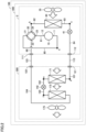
- Fig. 1 is a diagram showing a configuration of an air-conditioner 1 according to an embodiment.
- Fig. 1 functionally shows connection relation and an arrangement configuration of elements in air-conditioner 1, and does not necessarily show arrangement in a physical space.
- air-conditioner 1 includes a refrigerant circuit 4 and a control device 6.
- Refrigerant circuit 4 includes an outdoor unit 2 and an indoor unit 3.
- Indoor unit 3 includes a connection port 121 and a connection port 122.
- Outdoor unit 2 includes a connection port 112 and a connection port 111.
- Connection port 121 of indoor unit 3 is connected to connection port 112 of outdoor unit 2 through an extension pipe 113.
- Connection port 122 of indoor unit 3 is connected to connection port 111 of outdoor unit 2 through an extension pipe 123.
- Indoor unit 3 is thus constructed as being connectable to outdoor unit 2 through extension pipe 113 and extension pipe 123.
- Outdoor unit 2 includes a compressor 10, a four-way valve 20, an outdoor heat exchanger 30, and an expansion valve 41.
- Four-way valve 20 includes a connection port 21, a connection port 22, a connection port 23, and a connection port 24.
- Connection port 21 of four-way valve 20 is connected to a suction port 11 of compressor 10 through a pipe 85.
- Connection port 22 of four-way valve 20 is connected to connection port 111 of outdoor unit 2 through a pipe 86.
- Connection port 23 of four-way valve 20 is connected to a discharge port 12 of compressor 10 through a pipe 81.
- Connection port 24 of four-way valve 20 is connected to a one end side of outdoor heat exchanger 30 through a pipe 82.
- Outdoor heat exchanger 30 has the other end side connected to a one end side of expansion valve 41 through a pipe 83.
- Expansion valve 41 has the other end side connected to connection port 112 of outdoor unit 2 through a pipe 84.
- Air-conditioner 1 is controlled to any one of a plurality of types of air-conditioning modes including a cooling mode in which an indoor space to be air-conditioned is cooled and a heating mode in which the indoor space is heated.
- connection port 21 communicates with connection port 22 and connection port 23 communicates with connection port 24 as shown with a solid line in Fig. 1 .
- suction port 11 of compressor 10 communicates with indoor unit 3 and discharge port 12 of compressor 10 communicates with outdoor heat exchanger 30. Refrigerant thus flows through in the order of compressor 10, outdoor heat exchanger 30, expansion valve 41, and indoor unit 3.
- connection port 21 communicates with connection port 24 and connection port 22 communicates with connection port 23 as shown with a dashed line in Fig. 1 .
- suction port 11 of compressor 10 communicates with outdoor heat exchanger 30 and discharge port 12 of compressor 10 communicates with indoor unit 3. Refrigerant thus flows through in the order of compressor 10, indoor unit 3, expansion valve 41, and outdoor heat exchanger 30.
- Air-conditioner 1 is not limited to an air-conditioner capable of switching between the cooling mode and the heating mode by switching of four-way valve 20. Air-conditioner 1 does not have to include four-way valve 20 and refrigerant circuit 4 may be in a circuit configuration dedicated for the cooling mode.
- Control device 6 includes a processor 61 and a memory 62.
- Processor 61 is a processing entity that controls refrigerant circuit 4 by executing various programs.
- Processor 61 is implemented, for example, by at least any one of a central processing unit (CPU), a field programmable gate array (FPGA), and a graphics processing unit (GPU).
- Processor 61 may be implemented by processing circuitry.
- Memory 62 is implemented by a volatile memory such as a dynamic random access memory (DRAM) and a static random access memory (SRAM) or a non-volatile memory such as a read only memory (ROM).
- Memory 62 may include a solid state drive (SSD) or a hard disk drive (HDD).
- compressor 10 increases a pressure of gas refrigerant that flows from indoor unit 3 by suctioning gas refrigerant through suction port 11 and compressing suctioned gas refrigerant.
- Compressor 10 discharges gas refrigerant at a high temperature and a high pressure obtained by compression from discharge port 12 to outdoor heat exchanger 30.
- Compressor 10 is configured to be activated and deactivated and further to change in rotation speed during operations under the control by control device 6.
- Control device 6 changes a drive frequency of compressor 10 to any drive frequency by outputting a control signal to compressor 10.
- Compressor 10 changes in rotation speed with change in drive frequency to thereby adjust an amount of discharge of refrigerant.
- Various types of compressors can be adopted as compressor 10, and for example, a compressor of a scroll type, a rotary type, or a screw type can be adopted.
- Outdoor heat exchanger 30 has heat exchanged between gas refrigerant at the high temperature and the high pressure that flows from compressor 10 and outdoor air taken from an outdoor space by a fan 35.
- Refrigerant that has radiated heat to air by heat exchange in outdoor heat exchanger 30 changes to liquid refrigerant at the high temperature and the high pressure by condensing in outdoor heat exchanger 30.
- Liquid refrigerant at the high temperature and the high pressure obtained as a result of heat exchange in outdoor heat exchanger 30 flows out to expansion valve 41.
- Expansion valve 41 is, for example, a solenoid expansion valve, and lowers a pressure of liquid refrigerant at the high temperature and the high pressure that flows from outdoor heat exchanger 30. Refrigerant in a gas-liquid two-phase state obtained by pressure reduction by expansion valve 41 flows out to indoor unit 3.
- Indoor unit 3 has heat exchanged between refrigerant in the gas-liquid two-phase state that flows from outdoor unit 2 and air taken from the indoor space by a fan 75. Refrigerant that has absorbed heat from air as a result of heat exchange in indoor unit 3 evaporates in indoor unit 3 to change to gas refrigerant. Gas refrigerant at a low temperature and a low pressure obtained by heat exchange in indoor unit 3 flows out to compressor 10. Air from which heat has been absorbed by refrigerant in indoor unit 3 is blown again into the indoor space.
- air-conditioner 1 can cool the indoor space as refrigerant circulates through refrigerant circuit 4.
- FIG. 2 is a diagram showing a configuration of air-conditioner 100 according to the comparative example.
- features provided in air-conditioner 100 the same in function as the features provided in air-conditioner 1 according to the embodiment described above are given reference numerals the same as those of air-conditioner 1 according to the embodiment, and detailed description thereof will not be provided below.
- air-conditioner 100 includes a refrigerant circuit 400 including outdoor unit 2 and an indoor unit 300.
- Indoor unit 300 is connected to outdoor unit 2 through extension pipe 113 and extension pipe 123.
- Indoor unit 300 includes a first indoor heat exchanger 171, a second indoor heat exchanger 172, an expansion valve 142, and a fan 175.
- Connection port 121 of indoor unit 300 is connected to a one end side of first indoor heat exchanger 171 through a pipe 101.
- First indoor heat exchanger 171 has the other end side connected to a one end side of expansion valve 142 through a pipe 102.
- Expansion valve 142 has the other end side connected to a one end side of second indoor heat exchanger 172 through a pipe 103.
- Second indoor heat exchanger 172 has the other end side connected to connection port 122 of indoor unit 300 through a pipe 104.
- two indoor heat exchangers of first indoor heat exchanger 171 and second indoor heat exchanger 172 are connected in series and expansion valve 142 is provided between first indoor heat exchanger 171 and second indoor heat exchanger 172.
- First indoor heat exchanger 171 is located on the windward side in the direction of flow of air taken into indoor unit 300 from the indoor space by fan 175.
- Second indoor heat exchanger 172 is located on the leeward side in the direction of flow of air taken into indoor unit 300 from the indoor space by fan 175. Air taken into indoor unit 300 from the indoor space thus passes through first indoor heat exchanger 171 and thereafter through second indoor heat exchanger 172, and is blown again into the indoor space.
- Fig. 3 is a diagram showing change in quantity of exchanged heat in first indoor heat exchanger 171 and second indoor heat exchanger 172 in accordance with an open and closed state of expansion valve 142 in air-conditioner 100 according to the comparative example.
- the abscissa represents the open and closed state of expansion valve 142 and the ordinate represents the quantity of exchanged heat in each of first indoor heat exchanger 171 and second indoor heat exchanger 172.
- air-conditioner 100 can control the temperature and the humidity of air blown from indoor unit 300 into the indoor space by adjusting an opening of expansion valve 142. As shown in Fig. 3 , as expansion valve 142 changes from the closed state to the open state, the quantity of exchanged heat in first indoor heat exchanger 171 increases, whereas the quantity of exchanged heat in second indoor heat exchanger 172 decreases.
- State P can also be said as a state in which expansion valve 142 is open at such an opening that the quantity of exchanged heat in first indoor heat exchanger 171 is equal to the quantity of exchanged heat in second indoor heat exchanger 172.
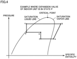
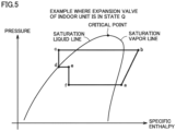
- Figs. 4 and 5 are pressure-enthalpy charts of the refrigeration cycle in air-conditioner 100 according to the comparative example.
- Fig. 4 shows the pressure-enthalpy chart in an example where expansion valve 142 of indoor unit 300 is in state P.
- Fig. 5 shows the pressure-enthalpy chart in an example where expansion valve 142 of indoor unit 300 is in state Q.
- the abscissa represents specific enthalpy and the ordinate represents a pressure of refrigerant.
- change of the graph from a point a until a point b represents change in state of refrigerant in compressor 10.
- Change of the graph from point b until a point c represents change in state of refrigerant in outdoor heat exchanger 30.
- Change of the graph from point c until a point d represents change in state of refrigerant in expansion valve 41.
- Change of the graph from point d until a point e represents change in state of refrigerant in first indoor heat exchanger 171.
- Change of the graph from point e until a point f represents change in state of refrigerant in expansion valve 142.
- Change of the graph from point f until point a represents change in state of refrigerant in second indoor heat exchanger 172.
- compressor 10 raises the pressure of gas refrigerant that flows from indoor unit 3 by compressing gas refrigerant. Gas refrigerant at the high temperature and the high pressure obtained by compression by compressor 10 flows out to outdoor heat exchanger 30.
- outdoor heat exchanger 30 has heat exchanged between gas refrigerant at the high temperature and the high pressure that flows from compressor 10 and air taken from the outdoor space by fan 35. Liquid refrigerant at the high temperature and the high pressure obtained by heat exchange in outdoor heat exchanger 30 flows out to expansion valve 142.
- expansion valve 41 lowers the pressure of liquid refrigerant at the high temperature and the high pressure that flows from outdoor heat exchanger 30. Refrigerant in the gas-liquid two-phase state at an intermediate temperature and an intermediate pressure obtained by pressure reduction by expansion valve 41 flows out to indoor unit 300.
- first indoor heat exchanger 171 has heat exchanged between refrigerant in the gas-liquid two-phase state that flows from expansion valve 41 in outdoor unit 2 and air taken from the indoor space by fan 175. Refrigerant in the gas-liquid two-phase state obtained by heat exchange in first indoor heat exchanger 171 flows out to expansion valve 142.
- Air taken into indoor unit 300 from the indoor space is cooled within a range equal to or higher than a dew point as a result of heat exchange in first indoor heat exchanger 171.
- first indoor heat exchanger 171 sensible heat that contributes to change in temperature of air is mainly exchanged.
- expansion valve 142 lowers the pressure of refrigerant in the gas-liquid two-phase state at the intermediate temperature and the intermediate pressure that flows from first indoor heat exchanger 171.
- Refrigerant reduced in pressure by expansion valve 142 becomes refrigerant in the gas-liquid two-phase state at a low temperature and a low pressure and flows out to second indoor heat exchanger 172.
- second indoor heat exchanger 172 has heat exchanged between refrigerant in the gas-liquid two-phase state that flows from expansion valve 142 and air that has exchanged heat in first indoor heat exchanger 171.
- Refrigerant in the gas-liquid two-phase state that has absorbed heat from air as a result of heat exchange in second indoor heat exchanger 172 changes to gas refrigerant.
- Gas refrigerant at the low temperature and the low pressure obtained by heat exchange in second indoor heat exchanger 172 flows out to compressor 10.
- Air taken into indoor unit 300 from the indoor space is cooled to a temperature lower than the dew point as a result of heat exchange in second indoor heat exchanger 172. Air taken into indoor unit 300 is thus dehumidified and blown again into the indoor space.
- heat exchange in second indoor heat exchanger 172 latent heat that contributes to change in state of moisture in air (dehumidification) is mainly exchanged.
- expansion valve 142 when expansion valve 142 is in state Q, expansion valve 142 is substantially in the closed state, and hence the temperature of refrigerant that flows through second indoor heat exchanger 172 is not different from the temperature of air taken from the indoor space. Therefore, heat is not substantially exchanged between refrigerant and air taken from the indoor space in first indoor heat exchanger 171.
- Fig. 6 is a diagram showing change in SHF of air in accordance with the open and closed state of expansion valve 142 in air-conditioner 100 according to the comparative example.
- the SHF represents an indicator indicating air-conditioning capability of the air-conditioner and it is also referred to as a sensible heat factor.
- the SHF is expressed by a ratio occupied by sensible heat to total heat which is total of sensible heat and latent heat.
- the abscissa represents the open and closed state of expansion valve 142 and the ordinate represents the SHF of air that passes through indoor unit 300.
- the quantity of exchanged heat in first indoor heat exchanger 171 where sensible heat is mainly exchanged is substantially equal to the quantity of exchanged heat in second indoor heat exchanger 172 where latent heat is mainly exchanged. Therefore, regarding the SHF of air, a ratio of sensible heat to total heat is substantially equal to a ratio of latent heat to total heat. For example, a value of the SHF is approximately 0.5.
- the quantity of exchanged heat in second indoor heat exchanger 172 where latent heat is mainly exchanged is larger than the quantity of exchanged heat in first indoor heat exchanger 171 where sensible heat is mainly exchanged. Therefore, regarding the SHF of air, the ratio of latent heat to total heat is higher than the ratio of sensible heat to total heat. For example, the value of SHF is smaller than approximately 0.5. Furthermore, when heat is substantially not exchanged in first indoor heat exchanger 171 as in this example, the value of SHF is close to 0.
- Air-conditioner 100 can thus control heat exchange in first indoor heat exchanger 171 where sensible heat is mainly exchanged and heat exchange in second indoor heat exchanger 172 where latent heat is mainly exchanged by adjusting the opening of expansion valve 142, to thereby control the temperature and the humidity of air blown into the indoor space from indoor unit 300.
- Fig. 7 is a diagram showing change in amount of refrigerant that remains in indoor unit 300, in accordance with the open and closed state of expansion valve 142 in air-conditioner 100 according to the comparative example.
- the abscissa represents the open and closed state of expansion valve 142 and the ordinate represents the amount of refrigerant that remains in each of first indoor heat exchanger 171 and second indoor heat exchanger 172.
- the amount of refrigerant that remains in the indoor unit is larger when expansion valve 142 is in state Q than when expansion valve 142 is in state P.
- most of liquid refrigerant remains in first indoor heat exchanger 171.
- an amount of refrigerant that flows through each of first indoor heat exchanger 171 and second indoor heat exchanger 172 cannot be adjusted to an appropriate amount.
- air-conditioner 100 according to the comparative example performs such a dehumidification operation as lowering the SHF of air, most of liquid refrigerant remains in first indoor heat exchanger 171.
- Refrigerant in an amount in consideration of remaining refrigerant should thus be sealed in advance in refrigerant circuit 400 in air-conditioner 100 according to the comparative example, which increases cost.
- Air-conditioner 1 is configured to be able to control the temperature and the humidity of air blown into the indoor space while cost is suppressed. Air-conditioner 1 according to the embodiment will specifically be described below.
- Air-conditioner 1 according to the embodiment will be described with reference to Figs. 1 and 8 .
- Fig. 1 is a diagram showing the configuration of air-conditioner 1 according to the embodiment.
- Fig. 8 is a diagram showing a configuration of indoor unit 3 according to the embodiment.
- air-conditioner 1 includes indoor unit 3 connected to outdoor unit 2 through extension pipe 113 and extension pipe 123.
- Indoor unit 3 includes first indoor heat exchanger 71, second indoor heat exchanger 72, a first expansion valve 42, a second expansion valve 43, and fan 75.
- Connection port 121 of indoor unit 3 is connected to the one end side of first indoor heat exchanger 71 through a pipe 91 and a pipe 92.
- First indoor heat exchanger 71 has the other end side connected to the one end side of first expansion valve 42 through a pipe 93.
- First expansion valve 42 has the other end side connected to connection port 122 of indoor unit 3 through a pipe 94 and a pipe 98.
- Connection port 121 of indoor unit 3 is connected to a one end side of second expansion valve 43 through pipe 91 and a pipe 95.
- Second expansion valve 43 has the other end side connected to a one end side of second indoor heat exchanger 72 through a pipe 96.
- Second indoor heat exchanger 72 has the other end side connected to connection port 122 of indoor unit 3 through a pipe 97 and pipe 98.
- a first path including pipe 92 to pipe 94 and a second path including pipe 95 to pipe 97 are connected in parallel between connection port 121 and connection port 122.
- two indoor heat exchangers of first indoor heat exchanger 71 and second indoor heat exchanger 72 are connected in parallel between connection port 121 and connection port 122.
- First expansion valve 42 is provided between first indoor heat exchanger 71 and connection port 122.
- first indoor heat exchanger 71 is located on the upstream side in the direction of flow of refrigerant and first expansion valve 42 is located on the downstream side in the direction of flow of refrigerant.
- First expansion valve 42 is a solenoid expansion valve that is opened and closed under the control (a control signal C2) by control device 6.
- Second expansion valve 43 is provided between connection port 121 and second indoor heat exchanger 72. In the cooling mode, second expansion valve 43 is located on the upstream side in the direction of flow of refrigerant and second indoor heat exchanger 72 is located on the downstream side in the direction of flow of refrigerant.
- Second expansion valve 43 is a solenoid expansion valve that is opened and closed under the control (a control signal C3) by control device 6.
- Air-conditioner 1 further includes a temperature sensor 51, a temperature sensor 52, a temperature sensor 53, a temperature sensor 54, and a humidity sensor 55.
- Temperature sensor 51 measures a temperature of refrigerant that flows between expansion valve 41 and connection port 112 and outputs a temperature T1 obtained as a result of measurement to control device 6.
- Temperature sensor 52 measures a temperature of refrigerant that flows between second expansion valve 43 and second indoor heat exchanger 72 and outputs a temperature T2 obtained as a result of measurement to control device 6.
- Temperature sensor 53 measures a temperature of refrigerant that flows between first indoor heat exchanger 71 and first expansion valve 42 and outputs a temperature T3 obtained as a result of measurement to control device 6.
- Temperature sensor 54 measures a temperature of refrigerant that flows between connection port 111 and compressor 10 and outputs a temperature T4 obtained as a result of measurement to control device 6.
- Humidity sensor 55 measures a humidity of air blown from indoor unit 3 and outputs a humidity H obtained as a result of measurement to control device 6.
- Control device 6 controls the opening of expansion valve 41 by outputting a control signal C1 to expansion valve 41.
- Control device 6 controls the opening of first expansion valve 42 by outputting control signal C2 to first expansion valve 42.
- Control device 6 controls the opening of second expansion valve 43 by outputting control signal C3 to second expansion valve 43.
- Fig. 8 is a diagram showing the configuration of indoor unit 3 according to the embodiment.
- indoor unit 3 includes first indoor heat exchanger 71 on the windward side and second indoor heat exchanger 72 on the leeward side such that first indoor heat exchanger 71 and second indoor heat exchanger 72 surround fan 75 from the windward side toward the leeward side in the direction of flow of air taken into indoor unit 3.
- First indoor heat exchanger 71 includes a plurality of indoor heat exchangers such as an indoor heat exchanger 71a, an indoor heat exchanger 71b, an indoor heat exchanger 71c, and an indoor heat exchanger 71d.
- Second indoor heat exchanger 72 includes a plurality of indoor heat exchangers such as an indoor heat exchanger 72a, an indoor heat exchanger 72b, an indoor heat exchanger 72c, and an indoor heat exchanger 72d.
- Air that has taken into indoor unit 3 from the indoor space by fan 75 passes through first indoor heat exchanger 71 (indoor heat exchangers 71a to 71d) and thereafter passes through second indoor heat exchanger 72 (indoor heat exchangers 72a to 71d) and is blown again into the indoor space.
- indoor unit 3 shown in Fig. 8 includes a line flow fan (trademark) as fan 75, it may include an axial fan as fan 75.
- fan 75 may be arranged on the windward side of first indoor heat exchanger 71 and second indoor heat exchanger 72.
- Fig. 9 is a diagram showing change in quantity of exchanged heat in first indoor heat exchanger 71 and second indoor heat exchanger 72 in accordance with the open and closed state of first expansion valve 42 and second expansion valve 43 in air-conditioner 1 according to the embodiment.
- the abscissa represents the open and closed state of first expansion valve 42 and second expansion valve 43 and the ordinate represents the quantity of exchanged heat in each of first indoor heat exchanger 71 and second indoor heat exchanger 72.
- air-conditioner 1 can control the temperature and the humidity of air blown into the indoor space from indoor unit 3 by adjusting the opening of each of first expansion valve 42 and second expansion valve 43. As shown in Fig. 9 , as first expansion valve 42 changes from the closed state to the open state and second expansion valve 43 changes from the open state to the closed state, the quantity of exchanged heat in first indoor heat exchanger 71 increases whereas the quantity of exchanged heat in second indoor heat exchanger 72 decreases.
- first expansion valve 42 and second expansion valve 43 when the state of opening of each of first expansion valve 42 and second expansion valve 43 falls under a state R, the quantity of exchanged heat in first indoor heat exchanger 71 is substantially equal to the quantity of exchanged heat in second indoor heat exchanger 72.
- State R can also be said as a state in which first expansion valve 42 and second expansion valve 43 are open at such an opening that the quantity of exchanged heat in first indoor heat exchanger 71 is equal to the quantity of exchanged heat in second indoor heat exchanger 72.
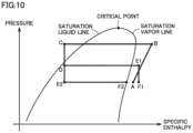
- Fig. 10 is a pressure-enthalpy chart of the refrigeration cycle in air-conditioner 1 according to the embodiment.
- Fig. 10 shows the pressure-enthalpy chart in an example where first expansion valve 42 and second expansion valve 43 in indoor unit 3 are in state R or state S.
- the abscissa represents specific enthalpy and the ordinate represents a pressure of refrigerant.
- change of the graph from a point A until a point B represents change in state of refrigerant in compressor 10.
- Change of the graph from point B until a point C represents change in state of refrigerant in outdoor heat exchanger 30.
- Change of the graph from point C until a point D represents change in state of refrigerant in expansion valve 41.
- Change of the graph from point D until a point E1 represents change in state of refrigerant in first indoor heat exchanger 71.
- Change of the graph from point E 1 until a point F 1 represents change in state of refrigerant in first expansion valve 42.
- Change of the graph from point D until a point E2 represents change in state of refrigerant in second expansion valve 43.
- Change of the graph from point E2 to a point F2 represents change in state of refrigerant in second indoor heat exchanger 72.
- compressor 10 raises the pressure of gas refrigerant that flows from indoor unit 3 by compressing gas refrigerant.
- Gas refrigerant at the high temperature and the high pressure obtained by compression by compressor 10 flows out to outdoor heat exchanger 30.
- outdoor heat exchanger 30 has heat exchanged between gas refrigerant at the high temperature and the high pressure that flows from compressor 10 and air taken from the outdoor space by fan 35. Liquid refrigerant at the high temperature and the high pressure obtained by heat exchange in outdoor heat exchanger 30 flows out to expansion valve 142.
- expansion valve 41 lowers the pressure of liquid refrigerant at the high temperature and the high pressure that flows from outdoor heat exchanger 30. Refrigerant in the gas-liquid two-phase state at the intermediate temperature and the intermediate pressure obtained by pressure reduction by expansion valve 41 flows out to indoor unit 3.
- first indoor heat exchanger 71 has heat exchanged between refrigerant in the gas-liquid two-phase state that flows from expansion valve 41 in outdoor unit 2 and air taken from the indoor space by fan 75.
- Refrigerant in the gas-liquid two-phase state that has absorbed heat from air as a result of heat exchange in first indoor heat exchanger 71 changes to gas refrigerant.
- Gas refrigerant at the intermediate temperature and the intermediate pressure obtained by heat exchange in first indoor heat exchanger 71 flows out to first expansion valve 42.
- Air taken into indoor unit 3 from the indoor space is cooled within a range equal to or higher than the dew point as a result of heat exchange in first indoor heat exchanger 71.
- sensible heat that contributes to change in temperature of air is mainly exchanged.
- first expansion valve 42 lowers the pressure of gas refrigerant at the intermediate temperature and the intermediate pressure that flows from first indoor heat exchanger 71. Refrigerant reduced in pressure by first expansion valve 42 becomes gas refrigerant at the low temperature and the low pressure and flows out to compressor 10.
- second expansion valve 43 lowers the pressure of refrigerant in the gas-liquid two-phase state that flows from expansion valve 41 in outdoor unit 2.
- Refrigerant reduced in pressure by second expansion valve 43 becomes refrigerant in the gas-liquid two-phase state at the low temperature and the low pressure and flows out to second indoor heat exchanger 72.
- second indoor heat exchanger 72 has heat exchanged between refrigerant in the gas-liquid two-phase state that flows from second expansion valve 43 and air that has exchanged heat in first indoor heat exchanger 71.
- Refrigerant in the gas-liquid two-phase state that has absorbed heat from air as a result of heat exchange in second indoor heat exchanger 72 changes to gas refrigerant.
- Gas refrigerant at the low temperature and the low pressure obtained by heat exchange in second indoor heat exchanger 72 flows out to compressor 10.
- Air taken into indoor unit 3 from the indoor space is cooled to a temperature lower than the dew point as a result of heat exchange in second indoor heat exchanger 72. Air taken into indoor unit 3 is thus dehumidified and blown again into the indoor space. Thus, in heat exchange in second indoor heat exchanger 72, latent heat that contributes to change in state of moisture in air (dehumidification) is mainly exchanged.
- Fig. 11 is a diagram showing change in SHF of air in accordance with the open and closed state of first expansion valve 42 and second expansion valve 43 in air-conditioner 1 according to the embodiment.
- the abscissa represents the open and closed state of first expansion valve 42 and second expansion valve 43 and the ordinate shows the SHF of air that flows through indoor unit 3.
- the quantity of exchanged heat in first indoor heat exchanger 71 where sensible heat is mainly exchanged is substantially equal to the quantity of exchanged heat in second indoor heat exchanger 72 where latent heat is mainly exchanged. Therefore, regarding the SHF of air, the ratio of sensible heat to total heat is substantially equal to the ratio of latent heat to total heat. For example, the value of the SHF is approximately 0.5.
- the quantity of exchanged heat in second indoor heat exchanger 72 where latent heat is mainly exchanged is larger than the quantity of exchanged heat in first indoor heat exchanger 71 where sensible heat is mainly exchanged. Therefore, regarding the SHF of air, the ratio of latent heat to total heat is higher than the ratio of sensible heat to total heat. For example, the value of SHF is smaller than approximately 0.5. Furthermore, when heat is substantially not exchanged in first indoor heat exchanger 71 as in this example, the value of SHF is close to 0.
- Air-conditioner 1 can thus control heat exchange in first indoor heat exchanger 71 where sensible heat is mainly exchanged and heat exchange in second indoor heat exchanger 72 where latent heat is mainly exchanged by adjusting the opening of each of first expansion valve 42 and second expansion valve 43, to thereby control the temperature and the humidity of air blown into the indoor space from indoor unit 3.
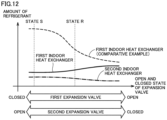
- Fig. 12 is a diagram showing change in amount of refrigerant that remains in indoor unit 3, in accordance with the open and closed state of first expansion valve 42 and second expansion valve 43 in air-conditioner 1 according to the embodiment.
- the abscissa represents the open and closed state of first expansion valve 42 and second expansion valve 43 and the ordinate represents an amount of refrigerant that remains in each of first indoor heat exchanger 71 and second indoor heat exchanger 72.
- the amount of refrigerant that remains in indoor unit 3 is substantially the same between the example where first expansion valve 42 and second expansion valve 43 are in state S and the example where first expansion valve 42 and second expansion valve 43 are in state S.
- the amount of refrigerant that remains in first indoor heat exchanger 71 is smaller when first expansion valve 42 and second expansion valve 43 are in state S than when first expansion valve 42 and second expansion valve 43 are in state R.
- first indoor heat exchanger 71 of air-conditioner 1 according to the embodiment can be smaller in amount of refrigerant that remains than first indoor heat exchanger 171 of air-conditioner 100 according to the comparative example.
- an amount of refrigerant that flows through each of first indoor heat exchanger 71 and second indoor heat exchanger 72 can be adjusted to an appropriate amount.
- air-conditioner 1 according to the embodiment performs such a dehumidification operation as lowering the SHF of air, it can minimize refrigerant that remains in first indoor heat exchanger 71 and second indoor heat exchanger 72.
- air-conditioner 1 in an amount in consideration of remaining refrigerant does not have to be sealed in advance in the refrigerant circuit, and air-conditioner 1 can control the temperature and the humidity of air blown into the indoor space while cost is suppressed.
- Fig. 13 is a flowchart for illustrating processing performed by control device 6 in air-conditioner 1 according to the embodiment.
- Control device 6 performs processing in the flowchart shown in Fig. 13 by executing a control program stored in memory 62. Processing in this flowchart is performed as being invoked from a main control routine of air-conditioner 1 every certain time period.
- "S" in the figure is used as an abbreviation of "STEP".
- Control device 6 determines whether or not humidity H of air blown from indoor unit 3 that is obtained from humidity sensor 55 is higher than a setting value h (S1). When humidity H is equal to or lower than setting value h (NO in S1), control device 6 decreases the opening of expansion valve 41 in outdoor unit 2 (S2). Air-conditioner 1 can thus decrease the amount of refrigerant that flows in indoor unit 3 to suppress dehumidification in indoor unit 3, and can thus appropriately achieve dehumidification.
- control device 6 When humidity H is higher than setting value h (YES in S1), control device 6 increases the opening of expansion valve 41 in outdoor unit 2 (S3). Air-conditioner 1 can thus increase the amount of refrigerant that flows in indoor unit 3 to promote dehumidification in indoor unit 3 so that dehumidification can appropriately be achieved.
- Control device 6 calculates a temperature difference A between temperature T3 of refrigerant that flows between first indoor heat exchanger 71 and first expansion valve 42 that is obtained from temperature sensor 53 and temperature T1 of refrigerant that flows between expansion valve 41 and connection port 112 that is obtained from temperature sensor 51 (S4).
- Control device 6 determines whether or not calculated temperature difference A is larger than a setting value a (S5). When temperature difference A is equal to or smaller than setting value a (NO in S5), control device 6 decreases the opening of first expansion valve 42 (S6). Air-conditioner 1 can thus decrease the amount of refrigerant that flows through first indoor heat exchanger 71 and can have heat appropriately exchanged in first indoor heat exchanger 71.
- control device 6 When temperature difference A is larger than setting value a (YES in S5), control device 6 increases the opening of first expansion valve 42 (S7). For example, when temperature T3 of refrigerant that flows between first indoor heat exchanger 71 and first expansion valve 42 is excessively higher than temperature T1 of refrigerant that flows between expansion valve 41 and connection port 112, heat may excessively be exchanged in first indoor heat exchanger 71. Therefore, control device 6 increases the amount of refrigerant that flows through first indoor heat exchanger 71 by increasing the opening of first expansion valve 42. Air-conditioner 1 can thus have heat appropriately exchanged in first indoor heat exchanger 71 and can set a constant degree of overheating at a flow outlet of first indoor heat exchanger 71.
- Control device 6 calculates a temperature difference B between temperature T4 of refrigerant that flows between connection port 111 and compressor 10 that is obtained from temperature sensor 54 and temperature T2 of refrigerant that flows between second expansion valve 43 and second indoor heat exchanger 72 that is obtained from temperature sensor 52 (S8).
- Control device 6 determines whether or not calculated temperature difference B is larger than a setting value b (S9).
- control device 6 decreases the opening of second expansion valve 43 (S10).
- S9 setting value b
- control device 6 decreases the opening of second expansion valve 43 (S10).
- Air-conditioner 1 can thus have heat appropriately exchanged in second indoor heat exchanger 72 and can prevent liquid refrigerant from flowing out to compressor 10 as much as possible.
- control device 6 When temperature difference B is larger than setting value b (YES in S9), control device 6 increases the opening of second expansion valve 43 (S 11). Air-conditioner 1 can thus increase the amount of refrigerant that flows through second indoor heat exchanger 72 and can have heat appropriately exchanged in second indoor heat exchanger 72. After processing in S10 or S11, control device 6 has control return to the main control routine.
- air-conditioner 1 controls each of expansion valve 41, first expansion valve 42, and second expansion valve 43 to thereby appropriately adjust the temperature and the humidity of air blown into the indoor space while heat is efficiently exchanged in indoor unit 3 between refrigerant and air taken from the indoor space.
- Air-conditioner 1 includes outdoor unit 2 and indoor unit 3.
- Indoor unit 3 includes connection port 121 connected to outdoor unit 2 and configured such that refrigerant flows therethrough, connection port 122 connected to outdoor unit 2 and configured such that refrigerant flows therethrough, a first path provided between connection port 121 and connection port 122, the first path including pipe 92 to pipe 94, a second path provided between connection port 121 and connection port 122 in parallel to pipe 92 to pipe 94, the second path including pipe 95 to pipe 97, first indoor heat exchanger 71 provided in the first path, first expansion valve 42 provided in the first path between first indoor heat exchanger 71 and connection port 122, second indoor heat exchanger 72 provided in the second path, and second expansion valve 43 provided in the second path between second indoor heat exchanger 72 and connection port 121.
- First indoor heat exchanger 71 is located on the windward side in the direction of flow of air taken into indoor unit 3.
- Second indoor heat exchanger 72 is located on the leeward side in the direction of flow of air taken into
- air-conditioner 1 in change of the quantity of exchanged heat in each of first indoor heat exchanger 71 and second indoor heat exchanger 72, air-conditioner 1 can adjust the amount of refrigerant that flows through each of first indoor heat exchanger 71 and second indoor heat exchanger 72 to an appropriate amount. Therefore, refrigerant in an amount in consideration of remaining refrigerant does not have to be sealed in advance in the refrigerant circuit and the temperature and the humidity of air blown into the indoor space can be controlled while cost is suppressed.
- air-conditioner 1 further includes control device 6 to control first expansion valve 42 and second expansion valve 43.
- air-conditioner 1 adjusts the opening of each of first expansion valve 42 and second expansion valve 43 to thereby appropriately adjust the temperature and the humidity of air blown into the indoor space while heat is efficiently exchanged in indoor unit 3 between refrigerant and air taken from the indoor space.
- outdoor unit 2 includes connection port 112 connected to connection port 121, connection port 111 connected to connection port 122, and compressor 10, outdoor heat exchanger 30, and expansion valve 41 arranged sequentially from connection port 111 toward connection port 112.
- Control device 6 further controls expansion valve 41.
- air-conditioner 1 can adjust the amount of refrigerant that flows through indoor unit 3 by adjusting the opening of expansion valve 41, and thus can efficiently exchange heat in indoor unit 3.
- control device controls expansion valve 41 based on the humidity of air blown from indoor unit 3 as shown in S1 to S3 in Fig. 13 .
- air-conditioner 1 can adjust the amount of refrigerant that flows through indoor unit 3 by adjusting the opening of expansion valve 41 based on the humidity of air blown from indoor unit 3, and thus can have indoor unit 3 appropriately achieve dehumidification.
- control device controls first expansion valve 42 based on a temperature of refrigerant that flows out of first indoor heat exchanger 71 and a temperature of refrigerant that flows out of expansion valve 41 as shown in S4 to S7 in Fig. 13 .
- air-conditioner 1 can adjust the amount of refrigerant that flows through first indoor heat exchanger 71 by adjusting the opening of first expansion valve 42, and can thus have heat appropriately exchanged in first indoor heat exchanger 71.
- control device controls second expansion valve 43 based on a temperature of refrigerant that flows into compressor 10 and a temperature of refrigerant that flows out of second expansion valve 43 as shown in S8 to S11 in Fig. 13 .
- air-conditioner 1 can adjust the amount of refrigerant that flows through second indoor heat exchanger 72 by adjusting the opening of second expansion valve 43, and can thus have heat appropriately exchanged in second indoor heat exchanger 72.
- Indoor unit 3 includes connection port 121 connected to outdoor unit 2 and configured such that refrigerant flows therethrough, connection port 122 connected to outdoor unit 2 and configured such that refrigerant flows therethrough, a first path provided between connection port 121 and connection port 122, the first path including pipe 92 to pipe 94, a second path provided between connection port 121 and connection port 122 in parallel to pipe 92 to pipe 94, the second path including pipe 95 to pipe 97, first indoor heat exchanger 71 provided in the first path, first expansion valve 42 provided in the first path between first indoor heat exchanger 71 and connection port 122, second indoor heat exchanger 72 provided in the second path, and second expansion valve 43 provided in the second path between second indoor heat exchanger 72 and connection port 121.
- First indoor heat exchanger 71 is located on the windward side in the direction of flow of air taken into indoor unit 3.
- Second indoor heat exchanger 72 is located on the leeward side in the direction of flow of air taken into the indoor unit.
- indoor unit 3 in change of the quantity of exchanged heat in each of first indoor heat exchanger 71 and second indoor heat exchanger 72, indoor unit 3 can adjust the amount of refrigerant that flows through each of first indoor heat exchanger 71 and second indoor heat exchanger 72 to an appropriate amount. Therefore, refrigerant in an amount in consideration of remaining refrigerant does not have to be sealed in advance in the refrigerant circuit and the temperature and the humidity of air blown into the indoor space can be controlled while cost is suppressed.
Landscapes
- Engineering & Computer Science (AREA)
- Mechanical Engineering (AREA)
- General Engineering & Computer Science (AREA)
- Physics & Mathematics (AREA)
- Thermal Sciences (AREA)
- Chemical & Material Sciences (AREA)
- Combustion & Propulsion (AREA)
- Air Conditioning Control Device (AREA)
- Air Filters, Heat-Exchange Apparatuses, And Housings Of Air-Conditioning Units (AREA)
Abstract
Description
- The present disclosure relates to an air-conditioner and an indoor unit.
- An air-conditioner to control a temperature and a humidity of air blown into an indoor space has conventionally been known.
-
Japanese Patent Laying-Open No. 2001-82761 - PTL 1:
Japanese Patent Laying-Open No. 2001-82761 - The air-conditioner disclosed in
Japanese Patent Laying-Open No. 2001-82761 - The present disclosure was made to solve the problem above, and an object thereof is to provide an air-conditioner and an indoor unit capable of controlling a temperature and a humidity of air blown into an indoor space while cost is suppressed.
- An air-conditioner according to the present disclosure includes an outdoor unit and an indoor unit. The indoor unit includes a first connection port connected to the outdoor unit, through which refrigerant flows, a second connection port connected to the outdoor unit, through which refrigerant flows, a first path provided between the first connection port and the second connection port, a second path provided between the first connection port and the second connection port in parallel to the first path, a first indoor heat exchanger provided in the first path, a first expansion valve provided in the first path between the first indoor heat exchanger and the second connection port, a second indoor heat exchanger provided in the second path, and a second expansion valve provided in the second path between the second indoor heat exchanger and the first connection port. The first indoor heat exchanger is located on a windward side in a direction of flow of air taken into the indoor unit. The second indoor heat exchanger is located on a leeward side in the direction of flow of air taken into the indoor unit.
- An indoor unit according to the present disclosure includes a first connection port connected to an outdoor unit, through which refrigerant flows, a second connection port connected to the outdoor unit, through which refrigerant flows, a first path provided between the first connection port and the second connection port, a second path provided between the first connection port and the second connection port in parallel to the first path, a first indoor heat exchanger provided in the first path, a first expansion valve provided in the first path between the first indoor heat exchanger and the second connection port, a second indoor heat exchanger provided in the second path, and a second expansion valve provided in the second path between the second indoor heat exchanger and the first connection port. The first indoor heat exchanger is located on a windward side in a direction of flow of air taken into the indoor unit. The second indoor heat exchanger is located on a leeward side in the direction of flow of air taken into the indoor unit.
- According to the present disclosure, a temperature and a humidity of air blown into an indoor space can be controlled while cost is suppressed.
-
-
Fig. 1 is a diagram showing a configuration of an air-conditioner according to an embodiment. -
Fig. 2 is a diagram showing a configuration of an air-conditioner according to a comparative example. -
Fig. 3 is a diagram showing change in quantity of exchanged heat in a first indoor heat exchanger and a second indoor heat exchanger in accordance with an open and closed state of an expansion valve in the air-conditioner according to the comparative example. -
Fig. 4 is a pressure-enthalpy chart of a refrigeration cycle in the air-conditioner according to the comparative example. -
Fig. 5 is a pressure-enthalpy chart of a refrigeration cycle in the air-conditioner according to the comparative example. -
Fig. 6 is a diagram showing change in SHF of air in accordance with an open and closed state of the expansion valve in the air-conditioner according to the comparative example. -
Fig. 7 is a diagram showing change in amount of refrigerant that remains in an indoor unit, in accordance with the open and closed state of the expansion valve in the air-conditioner according to the comparative example. -
Fig. 8 is a diagram showing a configuration of the indoor unit according to the embodiment. -
Fig. 9 is a diagram showing change in quantity of exchanged heat in the first indoor heat exchanger and the second indoor heat exchanger in accordance with the open and closed state of a first expansion valve and a second expansion valve in the air-conditioner according to the embodiment. -
Fig. 10 is a pressure-enthalpy chart of a refrigeration cycle in the air-conditioner according to the embodiment. -
Fig. 11 is a diagram showing change in SHF of air in accordance with the open and closed state of the first expansion valve and the second expansion valve in the air-conditioner according to the embodiment. -
Fig. 12 is a diagram showing change in amount of refrigerant in accordance with the open and closed state of the first expansion valve and the second expansion valve in the air-conditioner according to the embodiment. -
Fig. 13 is a flowchart for illustrating processing performed by a control device in the air-conditioner according to the embodiment. - An embodiment of the present disclosure will be described in detail below with reference to the drawings. Though a plurality of embodiments will be described below, combination of features described in the embodiments as appropriate is originally intended. The same or corresponding elements in the drawings have the same reference characters allotted and description thereof will not be repeated.
- Overview of an air-conditioner will be described with reference to
Fig. 1. Fig. 1 is a diagram showing a configuration of an air-conditioner 1 according to an embodiment.Fig. 1 functionally shows connection relation and an arrangement configuration of elements in air-conditioner 1, and does not necessarily show arrangement in a physical space. - As shown in
Fig. 1 , air-conditioner 1 includes a refrigerant circuit 4 and acontrol device 6. Refrigerant circuit 4 includes anoutdoor unit 2 and anindoor unit 3.Indoor unit 3 includes aconnection port 121 and aconnection port 122.Outdoor unit 2 includes aconnection port 112 and aconnection port 111.Connection port 121 ofindoor unit 3 is connected toconnection port 112 ofoutdoor unit 2 through anextension pipe 113.Connection port 122 ofindoor unit 3 is connected toconnection port 111 ofoutdoor unit 2 through anextension pipe 123.Indoor unit 3 is thus constructed as being connectable tooutdoor unit 2 throughextension pipe 113 andextension pipe 123. -
Outdoor unit 2 includes acompressor 10, a four-way valve 20, anoutdoor heat exchanger 30, and anexpansion valve 41. - Four-
way valve 20 includes aconnection port 21, aconnection port 22, aconnection port 23, and aconnection port 24.Connection port 21 of four-way valve 20 is connected to asuction port 11 ofcompressor 10 through apipe 85.Connection port 22 of four-way valve 20 is connected toconnection port 111 ofoutdoor unit 2 through apipe 86.Connection port 23 of four-way valve 20 is connected to adischarge port 12 ofcompressor 10 through apipe 81.Connection port 24 of four-way valve 20 is connected to a one end side ofoutdoor heat exchanger 30 through apipe 82.Outdoor heat exchanger 30 has the other end side connected to a one end side ofexpansion valve 41 through apipe 83.Expansion valve 41 has the other end side connected toconnection port 112 ofoutdoor unit 2 through apipe 84. - Air-
conditioner 1 is controlled to any one of a plurality of types of air-conditioning modes including a cooling mode in which an indoor space to be air-conditioned is cooled and a heating mode in which the indoor space is heated. - In the cooling mode, a state of communication in the inside of four-
way valve 20 is such thatconnection port 21 communicates withconnection port 22 andconnection port 23 communicates withconnection port 24 as shown with a solid line inFig. 1 . In other words, in the cooling mode,suction port 11 ofcompressor 10 communicates withindoor unit 3 anddischarge port 12 ofcompressor 10 communicates withoutdoor heat exchanger 30. Refrigerant thus flows through in the order ofcompressor 10,outdoor heat exchanger 30,expansion valve 41, andindoor unit 3. - In the heating mode, a state of communication in the inside of four-
way valve 20 is such thatconnection port 21 communicates withconnection port 24 andconnection port 22 communicates withconnection port 23 as shown with a dashed line inFig. 1 . In other words, in the heating mode,suction port 11 ofcompressor 10 communicates withoutdoor heat exchanger 30 anddischarge port 12 ofcompressor 10 communicates withindoor unit 3. Refrigerant thus flows through in the order ofcompressor 10,indoor unit 3,expansion valve 41, andoutdoor heat exchanger 30. - Air-
conditioner 1 is not limited to an air-conditioner capable of switching between the cooling mode and the heating mode by switching of four-way valve 20. Air-conditioner 1 does not have to include four-way valve 20 and refrigerant circuit 4 may be in a circuit configuration dedicated for the cooling mode. -
Control device 6 includes aprocessor 61 and amemory 62.Processor 61 is a processing entity that controls refrigerant circuit 4 by executing various programs.Processor 61 is implemented, for example, by at least any one of a central processing unit (CPU), a field programmable gate array (FPGA), and a graphics processing unit (GPU).Processor 61 may be implemented by processing circuitry.Memory 62 is implemented by a volatile memory such as a dynamic random access memory (DRAM) and a static random access memory (SRAM) or a non-volatile memory such as a read only memory (ROM).Memory 62 may include a solid state drive (SSD) or a hard disk drive (HDD). - In the cooling mode,
compressor 10 increases a pressure of gas refrigerant that flows fromindoor unit 3 by suctioning gas refrigerant throughsuction port 11 and compressing suctioned gas refrigerant.Compressor 10 discharges gas refrigerant at a high temperature and a high pressure obtained by compression fromdischarge port 12 tooutdoor heat exchanger 30.Compressor 10 is configured to be activated and deactivated and further to change in rotation speed during operations under the control bycontrol device 6.Control device 6 changes a drive frequency ofcompressor 10 to any drive frequency by outputting a control signal tocompressor 10.Compressor 10 changes in rotation speed with change in drive frequency to thereby adjust an amount of discharge of refrigerant. Various types of compressors can be adopted ascompressor 10, and for example, a compressor of a scroll type, a rotary type, or a screw type can be adopted. -
Outdoor heat exchanger 30 has heat exchanged between gas refrigerant at the high temperature and the high pressure that flows fromcompressor 10 and outdoor air taken from an outdoor space by afan 35. Refrigerant that has radiated heat to air by heat exchange inoutdoor heat exchanger 30 changes to liquid refrigerant at the high temperature and the high pressure by condensing inoutdoor heat exchanger 30. Liquid refrigerant at the high temperature and the high pressure obtained as a result of heat exchange inoutdoor heat exchanger 30 flows out toexpansion valve 41. -
Expansion valve 41 is, for example, a solenoid expansion valve, and lowers a pressure of liquid refrigerant at the high temperature and the high pressure that flows fromoutdoor heat exchanger 30. Refrigerant in a gas-liquid two-phase state obtained by pressure reduction byexpansion valve 41 flows out toindoor unit 3. -
Indoor unit 3 has heat exchanged between refrigerant in the gas-liquid two-phase state that flows fromoutdoor unit 2 and air taken from the indoor space by afan 75. Refrigerant that has absorbed heat from air as a result of heat exchange inindoor unit 3 evaporates inindoor unit 3 to change to gas refrigerant. Gas refrigerant at a low temperature and a low pressure obtained by heat exchange inindoor unit 3 flows out tocompressor 10. Air from which heat has been absorbed by refrigerant inindoor unit 3 is blown again into the indoor space. - As set forth above, air-
conditioner 1 can cool the indoor space as refrigerant circulates through refrigerant circuit 4. - An air-
conditioner 100 according to a comparative example will be described with reference toFig. 2. Fig. 2 is a diagram showing a configuration of air-conditioner 100 according to the comparative example. InFig. 2 , features provided in air-conditioner 100 the same in function as the features provided in air-conditioner 1 according to the embodiment described above are given reference numerals the same as those of air-conditioner 1 according to the embodiment, and detailed description thereof will not be provided below. - As shown in
Fig. 2 , air-conditioner 100 includes arefrigerant circuit 400 includingoutdoor unit 2 and anindoor unit 300.Indoor unit 300 is connected tooutdoor unit 2 throughextension pipe 113 andextension pipe 123.Indoor unit 300 includes a firstindoor heat exchanger 171, a secondindoor heat exchanger 172, anexpansion valve 142, and afan 175. -
Connection port 121 ofindoor unit 300 is connected to a one end side of firstindoor heat exchanger 171 through apipe 101. Firstindoor heat exchanger 171 has the other end side connected to a one end side ofexpansion valve 142 through apipe 102.Expansion valve 142 has the other end side connected to a one end side of secondindoor heat exchanger 172 through apipe 103. Secondindoor heat exchanger 172 has the other end side connected toconnection port 122 ofindoor unit 300 through apipe 104. - Thus, in air-
conditioner 100 according to the comparative example, two indoor heat exchangers of firstindoor heat exchanger 171 and secondindoor heat exchanger 172 are connected in series andexpansion valve 142 is provided between firstindoor heat exchanger 171 and secondindoor heat exchanger 172. - First
indoor heat exchanger 171 is located on the windward side in the direction of flow of air taken intoindoor unit 300 from the indoor space byfan 175. Secondindoor heat exchanger 172 is located on the leeward side in the direction of flow of air taken intoindoor unit 300 from the indoor space byfan 175. Air taken intoindoor unit 300 from the indoor space thus passes through firstindoor heat exchanger 171 and thereafter through secondindoor heat exchanger 172, and is blown again into the indoor space. - Control of a temperature and a humidity of air by air-
conditioner 100 according to the comparative example will be described with reference toFigs. 3 to 7 . -
Fig. 3 is a diagram showing change in quantity of exchanged heat in firstindoor heat exchanger 171 and secondindoor heat exchanger 172 in accordance with an open and closed state ofexpansion valve 142 in air-conditioner 100 according to the comparative example. InFig. 3 , the abscissa represents the open and closed state ofexpansion valve 142 and the ordinate represents the quantity of exchanged heat in each of firstindoor heat exchanger 171 and secondindoor heat exchanger 172. - In the cooling mode, air-
conditioner 100 can control the temperature and the humidity of air blown fromindoor unit 300 into the indoor space by adjusting an opening ofexpansion valve 142. As shown inFig. 3 , asexpansion valve 142 changes from the closed state to the open state, the quantity of exchanged heat in firstindoor heat exchanger 171 increases, whereas the quantity of exchanged heat in secondindoor heat exchanger 172 decreases. - For example, when a state of opening of
expansion valve 142 falls under a state P, the quantity of exchanged heat in firstindoor heat exchanger 171 is substantially equal to the quantity of exchanged heat in secondindoor heat exchanger 172. State P can also be said as a state in whichexpansion valve 142 is open at such an opening that the quantity of exchanged heat in firstindoor heat exchanger 171 is equal to the quantity of exchanged heat in secondindoor heat exchanger 172. - When
expansion valve 142 is in a state Q in which it is closed to a further extent as compared with state P, the quantity of exchanged heat in secondindoor heat exchanger 172 is larger than the quantity of exchanged heat in firstindoor heat exchanger 171. -
Figs. 4 and5 are pressure-enthalpy charts of the refrigeration cycle in air-conditioner 100 according to the comparative example.Fig. 4 shows the pressure-enthalpy chart in an example whereexpansion valve 142 ofindoor unit 300 is in state P.Fig. 5 shows the pressure-enthalpy chart in an example whereexpansion valve 142 ofindoor unit 300 is in state Q. InFigs. 4 and5 , the abscissa represents specific enthalpy and the ordinate represents a pressure of refrigerant. - In the refrigeration cycles in
Figs. 4 and5 , change of the graph from a point a until a point b represents change in state of refrigerant incompressor 10. Change of the graph from point b until a point c represents change in state of refrigerant inoutdoor heat exchanger 30. Change of the graph from point c until a point d represents change in state of refrigerant inexpansion valve 41. Change of the graph from point d until a point e represents change in state of refrigerant in firstindoor heat exchanger 171. Change of the graph from point e until a point f represents change in state of refrigerant inexpansion valve 142. Change of the graph from point f until point a represents change in state of refrigerant in secondindoor heat exchanger 172. - As shown with change of the graph from point a to point b,
compressor 10 raises the pressure of gas refrigerant that flows fromindoor unit 3 by compressing gas refrigerant. Gas refrigerant at the high temperature and the high pressure obtained by compression bycompressor 10 flows out tooutdoor heat exchanger 30. - As shown with change of the graph from point b to point c,
outdoor heat exchanger 30 has heat exchanged between gas refrigerant at the high temperature and the high pressure that flows fromcompressor 10 and air taken from the outdoor space byfan 35. Liquid refrigerant at the high temperature and the high pressure obtained by heat exchange inoutdoor heat exchanger 30 flows out toexpansion valve 142. - As shown with change of the graph from point c to point d,
expansion valve 41 lowers the pressure of liquid refrigerant at the high temperature and the high pressure that flows fromoutdoor heat exchanger 30. Refrigerant in the gas-liquid two-phase state at an intermediate temperature and an intermediate pressure obtained by pressure reduction byexpansion valve 41 flows out toindoor unit 300. - As shown with change of the graph from point d to point e, first
indoor heat exchanger 171 has heat exchanged between refrigerant in the gas-liquid two-phase state that flows fromexpansion valve 41 inoutdoor unit 2 and air taken from the indoor space byfan 175. Refrigerant in the gas-liquid two-phase state obtained by heat exchange in firstindoor heat exchanger 171 flows out toexpansion valve 142. - Air taken into
indoor unit 300 from the indoor space is cooled within a range equal to or higher than a dew point as a result of heat exchange in firstindoor heat exchanger 171. Thus, in heat exchange in firstindoor heat exchanger 171, sensible heat that contributes to change in temperature of air is mainly exchanged. - As shown with change of the graph from point e to point f,
expansion valve 142 lowers the pressure of refrigerant in the gas-liquid two-phase state at the intermediate temperature and the intermediate pressure that flows from firstindoor heat exchanger 171. Refrigerant reduced in pressure byexpansion valve 142 becomes refrigerant in the gas-liquid two-phase state at a low temperature and a low pressure and flows out to secondindoor heat exchanger 172. - As shown with change of the graph from point f to point a, second
indoor heat exchanger 172 has heat exchanged between refrigerant in the gas-liquid two-phase state that flows fromexpansion valve 142 and air that has exchanged heat in firstindoor heat exchanger 171. Refrigerant in the gas-liquid two-phase state that has absorbed heat from air as a result of heat exchange in secondindoor heat exchanger 172 changes to gas refrigerant. Gas refrigerant at the low temperature and the low pressure obtained by heat exchange in secondindoor heat exchanger 172 flows out tocompressor 10. - Air taken into
indoor unit 300 from the indoor space is cooled to a temperature lower than the dew point as a result of heat exchange in secondindoor heat exchanger 172. Air taken intoindoor unit 300 is thus dehumidified and blown again into the indoor space. Thus, in heat exchange in secondindoor heat exchanger 172, latent heat that contributes to change in state of moisture in air (dehumidification) is mainly exchanged. - As shown in
Fig. 3 , whenexpansion valve 142 is in state P, the quantity of exchanged heat in firstindoor heat exchanger 171 is substantially equal to the quantity of exchanged heat in secondindoor heat exchanger 172. Therefore, as shown inFig. 4 , an amount of change in specific enthalpy is substantially the same between change of the graph from point d to point e and change of the graph from point f to point a. - On the other hand, as shown in
Fig. 3 , whenexpansion valve 142 is in state Q, the quantity of exchanged heat in secondindoor heat exchanger 172 is larger than the quantity of exchanged heat in firstindoor heat exchanger 171. Therefore, as shown inFig. 5 , change of the graph from point f to point a is larger in amount of change in specific enthalpy than change of the graph from point d to point e. - More specifically, when
expansion valve 142 is in state Q,expansion valve 142 is substantially in the closed state, and hence the temperature of refrigerant that flows through secondindoor heat exchanger 172 is not different from the temperature of air taken from the indoor space. Therefore, heat is not substantially exchanged between refrigerant and air taken from the indoor space in firstindoor heat exchanger 171. -
Fig. 6 is a diagram showing change in SHF of air in accordance with the open and closed state ofexpansion valve 142 in air-conditioner 100 according to the comparative example. The SHF represents an indicator indicating air-conditioning capability of the air-conditioner and it is also referred to as a sensible heat factor. The SHF is expressed by a ratio occupied by sensible heat to total heat which is total of sensible heat and latent heat. InFig. 6 , the abscissa represents the open and closed state ofexpansion valve 142 and the ordinate represents the SHF of air that passes throughindoor unit 300. - As shown in
Fig. 6 , whenexpansion valve 142 is in state P, the quantity of exchanged heat in firstindoor heat exchanger 171 where sensible heat is mainly exchanged is substantially equal to the quantity of exchanged heat in secondindoor heat exchanger 172 where latent heat is mainly exchanged. Therefore, regarding the SHF of air, a ratio of sensible heat to total heat is substantially equal to a ratio of latent heat to total heat. For example, a value of the SHF is approximately 0.5. - On the other hand, when
expansion valve 142 is in state Q, the quantity of exchanged heat in secondindoor heat exchanger 172 where latent heat is mainly exchanged is larger than the quantity of exchanged heat in firstindoor heat exchanger 171 where sensible heat is mainly exchanged. Therefore, regarding the SHF of air, the ratio of latent heat to total heat is higher than the ratio of sensible heat to total heat. For example, the value of SHF is smaller than approximately 0.5. Furthermore, when heat is substantially not exchanged in firstindoor heat exchanger 171 as in this example, the value of SHF is close to 0. - Air-
conditioner 100 can thus control heat exchange in firstindoor heat exchanger 171 where sensible heat is mainly exchanged and heat exchange in secondindoor heat exchanger 172 where latent heat is mainly exchanged by adjusting the opening ofexpansion valve 142, to thereby control the temperature and the humidity of air blown into the indoor space fromindoor unit 300. -
Fig. 7 is a diagram showing change in amount of refrigerant that remains inindoor unit 300, in accordance with the open and closed state ofexpansion valve 142 in air-conditioner 100 according to the comparative example. InFig. 7 , the abscissa represents the open and closed state ofexpansion valve 142 and the ordinate represents the amount of refrigerant that remains in each of firstindoor heat exchanger 171 and secondindoor heat exchanger 172. - As shown in
Fig. 7 , the amount of refrigerant that remains in the indoor unit is larger whenexpansion valve 142 is in state Q than whenexpansion valve 142 is in state P. In particular, when heat is substantially not exchanged in firstindoor heat exchanger 171 as in the case whereexpansion valve 142 is in state Q, most of liquid refrigerant remains in firstindoor heat exchanger 171. - Thus, in change of the quantity of exchanged heat in each of first
indoor heat exchanger 171 and secondindoor heat exchanger 172, in air-conditioner 100 according to the comparative example, an amount of refrigerant that flows through each of firstindoor heat exchanger 171 and secondindoor heat exchanger 172 cannot be adjusted to an appropriate amount. In particular, when air-conditioner 100 according to the comparative example performs such a dehumidification operation as lowering the SHF of air, most of liquid refrigerant remains in firstindoor heat exchanger 171. Refrigerant in an amount in consideration of remaining refrigerant should thus be sealed in advance inrefrigerant circuit 400 in air-conditioner 100 according to the comparative example, which increases cost. - Air-
conditioner 1 according to the embodiment is configured to be able to control the temperature and the humidity of air blown into the indoor space while cost is suppressed. Air-conditioner 1 according to the embodiment will specifically be described below. - Air-
conditioner 1 according to the embodiment will be described with reference toFigs. 1 and8 .Fig. 1 is a diagram showing the configuration of air-conditioner 1 according to the embodiment.Fig. 8 is a diagram showing a configuration ofindoor unit 3 according to the embodiment. - As shown in
Fig. 1 , air-conditioner 1 includesindoor unit 3 connected tooutdoor unit 2 throughextension pipe 113 andextension pipe 123.Indoor unit 3 includes firstindoor heat exchanger 71, secondindoor heat exchanger 72, afirst expansion valve 42, asecond expansion valve 43, andfan 75. -
Connection port 121 ofindoor unit 3 is connected to the one end side of firstindoor heat exchanger 71 through apipe 91 and apipe 92. Firstindoor heat exchanger 71 has the other end side connected to the one end side offirst expansion valve 42 through apipe 93.First expansion valve 42 has the other end side connected toconnection port 122 ofindoor unit 3 through apipe 94 and apipe 98. -
Connection port 121 ofindoor unit 3 is connected to a one end side ofsecond expansion valve 43 throughpipe 91 and apipe 95.Second expansion valve 43 has the other end side connected to a one end side of secondindoor heat exchanger 72 through apipe 96. Secondindoor heat exchanger 72 has the other end side connected toconnection port 122 ofindoor unit 3 through apipe 97 andpipe 98. - Thus, in air-
conditioner 1 according to the embodiment, a firstpath including pipe 92 topipe 94 and a secondpath including pipe 95 topipe 97 are connected in parallel betweenconnection port 121 andconnection port 122. In other words, two indoor heat exchangers of firstindoor heat exchanger 71 and secondindoor heat exchanger 72 are connected in parallel betweenconnection port 121 andconnection port 122. -
First expansion valve 42 is provided between firstindoor heat exchanger 71 andconnection port 122. In the cooling mode, firstindoor heat exchanger 71 is located on the upstream side in the direction of flow of refrigerant andfirst expansion valve 42 is located on the downstream side in the direction of flow of refrigerant.First expansion valve 42 is a solenoid expansion valve that is opened and closed under the control (a control signal C2) bycontrol device 6.Second expansion valve 43 is provided betweenconnection port 121 and secondindoor heat exchanger 72. In the cooling mode,second expansion valve 43 is located on the upstream side in the direction of flow of refrigerant and secondindoor heat exchanger 72 is located on the downstream side in the direction of flow of refrigerant.Second expansion valve 43 is a solenoid expansion valve that is opened and closed under the control (a control signal C3) bycontrol device 6. - Air-
conditioner 1 further includes atemperature sensor 51, atemperature sensor 52, atemperature sensor 53, atemperature sensor 54, and ahumidity sensor 55. -
Temperature sensor 51 measures a temperature of refrigerant that flows betweenexpansion valve 41 andconnection port 112 and outputs a temperature T1 obtained as a result of measurement to controldevice 6.Temperature sensor 52 measures a temperature of refrigerant that flows betweensecond expansion valve 43 and secondindoor heat exchanger 72 and outputs a temperature T2 obtained as a result of measurement to controldevice 6.Temperature sensor 53 measures a temperature of refrigerant that flows between firstindoor heat exchanger 71 andfirst expansion valve 42 and outputs a temperature T3 obtained as a result of measurement to controldevice 6.Temperature sensor 54 measures a temperature of refrigerant that flows betweenconnection port 111 andcompressor 10 and outputs a temperature T4 obtained as a result of measurement to controldevice 6.Humidity sensor 55 measures a humidity of air blown fromindoor unit 3 and outputs a humidity H obtained as a result of measurement to controldevice 6. -
Control device 6 controls the opening ofexpansion valve 41 by outputting a control signal C1 toexpansion valve 41.Control device 6 controls the opening offirst expansion valve 42 by outputting control signal C2 tofirst expansion valve 42.Control device 6 controls the opening ofsecond expansion valve 43 by outputting control signal C3 tosecond expansion valve 43. -
Fig. 8 is a diagram showing the configuration ofindoor unit 3 according to the embodiment. As shown inFig. 8 ,indoor unit 3 includes firstindoor heat exchanger 71 on the windward side and secondindoor heat exchanger 72 on the leeward side such that firstindoor heat exchanger 71 and secondindoor heat exchanger 72surround fan 75 from the windward side toward the leeward side in the direction of flow of air taken intoindoor unit 3. Firstindoor heat exchanger 71 includes a plurality of indoor heat exchangers such as anindoor heat exchanger 71a, anindoor heat exchanger 71b, anindoor heat exchanger 71c, and anindoor heat exchanger 71d. Secondindoor heat exchanger 72 includes a plurality of indoor heat exchangers such as anindoor heat exchanger 72a, anindoor heat exchanger 72b, anindoor heat exchanger 72c, and anindoor heat exchanger 72d. - Air that has taken into
indoor unit 3 from the indoor space byfan 75 passes through first indoor heat exchanger 71 (indoor heat exchangers 71a to 71d) and thereafter passes through second indoor heat exchanger 72 (indoor heat exchangers 72a to 71d) and is blown again into the indoor space. - Though
indoor unit 3 shown inFig. 8 includes a line flow fan (trademark) asfan 75, it may include an axial fan asfan 75. When the axial fan is employed asfan 75,fan 75 may be arranged on the windward side of firstindoor heat exchanger 71 and secondindoor heat exchanger 72. - Control of the temperature and the humidity of air by air-
conditioner 1 according to the embodiment will be described with reference toFigs. 9 to 13 . -
Fig. 9 is a diagram showing change in quantity of exchanged heat in firstindoor heat exchanger 71 and secondindoor heat exchanger 72 in accordance with the open and closed state offirst expansion valve 42 andsecond expansion valve 43 in air-conditioner 1 according to the embodiment. InFig. 9 , the abscissa represents the open and closed state offirst expansion valve 42 andsecond expansion valve 43 and the ordinate represents the quantity of exchanged heat in each of firstindoor heat exchanger 71 and secondindoor heat exchanger 72. - In the cooling mode, air-
conditioner 1 can control the temperature and the humidity of air blown into the indoor space fromindoor unit 3 by adjusting the opening of each offirst expansion valve 42 andsecond expansion valve 43. As shown inFig. 9 , asfirst expansion valve 42 changes from the closed state to the open state andsecond expansion valve 43 changes from the open state to the closed state, the quantity of exchanged heat in firstindoor heat exchanger 71 increases whereas the quantity of exchanged heat in secondindoor heat exchanger 72 decreases. - For example, when the state of opening of each of
first expansion valve 42 andsecond expansion valve 43 falls under a state R, the quantity of exchanged heat in firstindoor heat exchanger 71 is substantially equal to the quantity of exchanged heat in secondindoor heat exchanger 72. State R can also be said as a state in whichfirst expansion valve 42 andsecond expansion valve 43 are open at such an opening that the quantity of exchanged heat in firstindoor heat exchanger 71 is equal to the quantity of exchanged heat in secondindoor heat exchanger 72. - When the state falls under a state S in which
first expansion valve 42 is closed to a further extent as compared with state R andsecond expansion valve 43 is open to a further extent as compared with state R, the quantity of exchanged heat in secondindoor heat exchanger 72 is larger than the quantity of exchanged heat in firstindoor heat exchanger 71. -
Fig. 10 is a pressure-enthalpy chart of the refrigeration cycle in air-conditioner 1 according to the embodiment.Fig. 10 shows the pressure-enthalpy chart in an example wherefirst expansion valve 42 andsecond expansion valve 43 inindoor unit 3 are in state R or state S. InFig. 10 , the abscissa represents specific enthalpy and the ordinate represents a pressure of refrigerant. - In the refrigeration cycle in
Fig. 10 , change of the graph from a point A until a point B represents change in state of refrigerant incompressor 10. Change of the graph from point B until a point C represents change in state of refrigerant inoutdoor heat exchanger 30. Change of the graph from point C until a point D represents change in state of refrigerant inexpansion valve 41. Change of the graph from point D until a point E1 represents change in state of refrigerant in firstindoor heat exchanger 71. Change of the graph frompoint E 1 until apoint F 1 represents change in state of refrigerant infirst expansion valve 42. Change of the graph from point D until a point E2 represents change in state of refrigerant insecond expansion valve 43. Change of the graph from point E2 to a point F2 represents change in state of refrigerant in secondindoor heat exchanger 72. - As shown with change of the graph from point A to point B,
compressor 10 raises the pressure of gas refrigerant that flows fromindoor unit 3 by compressing gas refrigerant. Gas refrigerant at the high temperature and the high pressure obtained by compression bycompressor 10 flows out tooutdoor heat exchanger 30. - As shown with change of the graph from point B to point C,
outdoor heat exchanger 30 has heat exchanged between gas refrigerant at the high temperature and the high pressure that flows fromcompressor 10 and air taken from the outdoor space byfan 35. Liquid refrigerant at the high temperature and the high pressure obtained by heat exchange inoutdoor heat exchanger 30 flows out toexpansion valve 142. - As shown with change of the graph from point C to point D,
expansion valve 41 lowers the pressure of liquid refrigerant at the high temperature and the high pressure that flows fromoutdoor heat exchanger 30. Refrigerant in the gas-liquid two-phase state at the intermediate temperature and the intermediate pressure obtained by pressure reduction byexpansion valve 41 flows out toindoor unit 3. - As shown with change of the graph from point D to point E1, first
indoor heat exchanger 71 has heat exchanged between refrigerant in the gas-liquid two-phase state that flows fromexpansion valve 41 inoutdoor unit 2 and air taken from the indoor space byfan 75. Refrigerant in the gas-liquid two-phase state that has absorbed heat from air as a result of heat exchange in firstindoor heat exchanger 71 changes to gas refrigerant. Gas refrigerant at the intermediate temperature and the intermediate pressure obtained by heat exchange in firstindoor heat exchanger 71 flows out tofirst expansion valve 42. - Air taken into
indoor unit 3 from the indoor space is cooled within a range equal to or higher than the dew point as a result of heat exchange in firstindoor heat exchanger 71. Thus, in heat exchange in firstindoor heat exchanger 71, sensible heat that contributes to change in temperature of air is mainly exchanged. - As shown with change of the graph from point E1 to point F1,
first expansion valve 42 lowers the pressure of gas refrigerant at the intermediate temperature and the intermediate pressure that flows from firstindoor heat exchanger 71. Refrigerant reduced in pressure byfirst expansion valve 42 becomes gas refrigerant at the low temperature and the low pressure and flows out tocompressor 10. - As shown with change of the graph from point D to point E2,
second expansion valve 43 lowers the pressure of refrigerant in the gas-liquid two-phase state that flows fromexpansion valve 41 inoutdoor unit 2. Refrigerant reduced in pressure bysecond expansion valve 43 becomes refrigerant in the gas-liquid two-phase state at the low temperature and the low pressure and flows out to secondindoor heat exchanger 72. - As shown with change of the graph from point E2 to point F2, second
indoor heat exchanger 72 has heat exchanged between refrigerant in the gas-liquid two-phase state that flows fromsecond expansion valve 43 and air that has exchanged heat in firstindoor heat exchanger 71. Refrigerant in the gas-liquid two-phase state that has absorbed heat from air as a result of heat exchange in secondindoor heat exchanger 72 changes to gas refrigerant. Gas refrigerant at the low temperature and the low pressure obtained by heat exchange in secondindoor heat exchanger 72 flows out tocompressor 10. - Air taken into
indoor unit 3 from the indoor space is cooled to a temperature lower than the dew point as a result of heat exchange in secondindoor heat exchanger 72. Air taken intoindoor unit 3 is thus dehumidified and blown again into the indoor space. Thus, in heat exchange in secondindoor heat exchanger 72, latent heat that contributes to change in state of moisture in air (dehumidification) is mainly exchanged. - Gas refrigerant at the low temperature and the low pressure that flows out of
first expansion valve 42 and gas refrigerant at the low temperature and the low pressure that flows out of secondindoor heat exchanger 72 merge inpipe 98 and flow out tocompressor 10. -
Fig. 11 is a diagram showing change in SHF of air in accordance with the open and closed state offirst expansion valve 42 andsecond expansion valve 43 in air-conditioner 1 according to the embodiment. InFig. 11 , the abscissa represents the open and closed state offirst expansion valve 42 andsecond expansion valve 43 and the ordinate shows the SHF of air that flows throughindoor unit 3. - As shown in
Fig. 11 , whenfirst expansion valve 42 andsecond expansion valve 43 are in state R, the quantity of exchanged heat in firstindoor heat exchanger 71 where sensible heat is mainly exchanged is substantially equal to the quantity of exchanged heat in secondindoor heat exchanger 72 where latent heat is mainly exchanged. Therefore, regarding the SHF of air, the ratio of sensible heat to total heat is substantially equal to the ratio of latent heat to total heat. For example, the value of the SHF is approximately 0.5. - On the other hand, when
first expansion valve 42 andsecond expansion valve 43 are in state S, the quantity of exchanged heat in secondindoor heat exchanger 72 where latent heat is mainly exchanged is larger than the quantity of exchanged heat in firstindoor heat exchanger 71 where sensible heat is mainly exchanged. Therefore, regarding the SHF of air, the ratio of latent heat to total heat is higher than the ratio of sensible heat to total heat. For example, the value of SHF is smaller than approximately 0.5. Furthermore, when heat is substantially not exchanged in firstindoor heat exchanger 71 as in this example, the value of SHF is close to 0. - Air-
conditioner 1 can thus control heat exchange in firstindoor heat exchanger 71 where sensible heat is mainly exchanged and heat exchange in secondindoor heat exchanger 72 where latent heat is mainly exchanged by adjusting the opening of each offirst expansion valve 42 andsecond expansion valve 43, to thereby control the temperature and the humidity of air blown into the indoor space fromindoor unit 3. -
Fig. 12 is a diagram showing change in amount of refrigerant that remains inindoor unit 3, in accordance with the open and closed state offirst expansion valve 42 andsecond expansion valve 43 in air-conditioner 1 according to the embodiment. InFig. 12 , the abscissa represents the open and closed state offirst expansion valve 42 andsecond expansion valve 43 and the ordinate represents an amount of refrigerant that remains in each of firstindoor heat exchanger 71 and secondindoor heat exchanger 72. - As shown in
Fig. 12 , the amount of refrigerant that remains inindoor unit 3 is substantially the same between the example wherefirst expansion valve 42 andsecond expansion valve 43 are in state S and the example wherefirst expansion valve 42 andsecond expansion valve 43 are in state S. In particular, the amount of refrigerant that remains in firstindoor heat exchanger 71 is smaller whenfirst expansion valve 42 andsecond expansion valve 43 are in state S than whenfirst expansion valve 42 andsecond expansion valve 43 are in state R. ThoughFig. 12 shows also the amount of refrigerant that remains in firstindoor heat exchanger 171 of air-conditioner 100 according to the comparative example, firstindoor heat exchanger 71 of air-conditioner 1 according to the embodiment can be smaller in amount of refrigerant that remains than firstindoor heat exchanger 171 of air-conditioner 100 according to the comparative example. - Thus, in change of the quantity of exchanged heat in each of first
indoor heat exchanger 71 and secondindoor heat exchanger 72, in air-conditioner 1 according to the embodiment, an amount of refrigerant that flows through each of firstindoor heat exchanger 71 and secondindoor heat exchanger 72 can be adjusted to an appropriate amount. In particular, even when air-conditioner 1 according to the embodiment performs such a dehumidification operation as lowering the SHF of air, it can minimize refrigerant that remains in firstindoor heat exchanger 71 and secondindoor heat exchanger 72. Thus, in air-conditioner 1 according to the embodiment, refrigerant in an amount in consideration of remaining refrigerant does not have to be sealed in advance in the refrigerant circuit, and air-conditioner 1 can control the temperature and the humidity of air blown into the indoor space while cost is suppressed. -
Fig. 13 is a flowchart for illustrating processing performed bycontrol device 6 in air-conditioner 1 according to the embodiment.Control device 6 performs processing in the flowchart shown inFig. 13 by executing a control program stored inmemory 62. Processing in this flowchart is performed as being invoked from a main control routine of air-conditioner 1 every certain time period. "S" in the figure is used as an abbreviation of "STEP". -
Control device 6 determines whether or not humidity H of air blown fromindoor unit 3 that is obtained fromhumidity sensor 55 is higher than a setting value h (S1). When humidity H is equal to or lower than setting value h (NO in S1),control device 6 decreases the opening ofexpansion valve 41 in outdoor unit 2 (S2). Air-conditioner 1 can thus decrease the amount of refrigerant that flows inindoor unit 3 to suppress dehumidification inindoor unit 3, and can thus appropriately achieve dehumidification. - When humidity H is higher than setting value h (YES in S1),
control device 6 increases the opening ofexpansion valve 41 in outdoor unit 2 (S3). Air-conditioner 1 can thus increase the amount of refrigerant that flows inindoor unit 3 to promote dehumidification inindoor unit 3 so that dehumidification can appropriately be achieved. -
Control device 6 calculates a temperature difference A between temperature T3 of refrigerant that flows between firstindoor heat exchanger 71 andfirst expansion valve 42 that is obtained fromtemperature sensor 53 and temperature T1 of refrigerant that flows betweenexpansion valve 41 andconnection port 112 that is obtained from temperature sensor 51 (S4). -
Control device 6 determines whether or not calculated temperature difference A is larger than a setting value a (S5). When temperature difference A is equal to or smaller than setting value a (NO in S5),control device 6 decreases the opening of first expansion valve 42 (S6). Air-conditioner 1 can thus decrease the amount of refrigerant that flows through firstindoor heat exchanger 71 and can have heat appropriately exchanged in firstindoor heat exchanger 71. - When temperature difference A is larger than setting value a (YES in S5),
control device 6 increases the opening of first expansion valve 42 (S7). For example, when temperature T3 of refrigerant that flows between firstindoor heat exchanger 71 andfirst expansion valve 42 is excessively higher than temperature T1 of refrigerant that flows betweenexpansion valve 41 andconnection port 112, heat may excessively be exchanged in firstindoor heat exchanger 71. Therefore,control device 6 increases the amount of refrigerant that flows through firstindoor heat exchanger 71 by increasing the opening offirst expansion valve 42. Air-conditioner 1 can thus have heat appropriately exchanged in firstindoor heat exchanger 71 and can set a constant degree of overheating at a flow outlet of firstindoor heat exchanger 71. -
Control device 6 calculates a temperature difference B between temperature T4 of refrigerant that flows betweenconnection port 111 andcompressor 10 that is obtained fromtemperature sensor 54 and temperature T2 of refrigerant that flows betweensecond expansion valve 43 and secondindoor heat exchanger 72 that is obtained from temperature sensor 52 (S8). -
Control device 6 determines whether or not calculated temperature difference B is larger than a setting value b (S9). When temperature difference B is equal to or smaller than setting value b (NO in S9),control device 6 decreases the opening of second expansion valve 43 (S10). For example, when the difference between temperature T4 of refrigerant that flows betweenconnection port 111 andcompressor 10 and temperature T2 of refrigerant that flows betweensecond expansion valve 43 and secondindoor heat exchanger 72 is excessively small, heat exchange may be insufficient and liquid refrigerant may flow out tocompressor 10. Therefore,control device 6 decreases the amount of refrigerant that flows through secondindoor heat exchanger 72 by decreasing the opening offirst expansion valve 42. Air-conditioner 1 can thus have heat appropriately exchanged in secondindoor heat exchanger 72 and can prevent liquid refrigerant from flowing out tocompressor 10 as much as possible. - When temperature difference B is larger than setting value b (YES in S9),
control device 6 increases the opening of second expansion valve 43 (S 11). Air-conditioner 1 can thus increase the amount of refrigerant that flows through secondindoor heat exchanger 72 and can have heat appropriately exchanged in secondindoor heat exchanger 72. After processing in S10 or S11,control device 6 has control return to the main control routine. - As set forth above, air-
conditioner 1 controls each ofexpansion valve 41,first expansion valve 42, andsecond expansion valve 43 to thereby appropriately adjust the temperature and the humidity of air blown into the indoor space while heat is efficiently exchanged inindoor unit 3 between refrigerant and air taken from the indoor space. - The present disclosure relates to air-
conditioner 1. Air-conditioner 1 includesoutdoor unit 2 andindoor unit 3.Indoor unit 3 includesconnection port 121 connected tooutdoor unit 2 and configured such that refrigerant flows therethrough,connection port 122 connected tooutdoor unit 2 and configured such that refrigerant flows therethrough, a first path provided betweenconnection port 121 andconnection port 122, the firstpath including pipe 92 topipe 94, a second path provided betweenconnection port 121 andconnection port 122 in parallel topipe 92 topipe 94, the secondpath including pipe 95 topipe 97, firstindoor heat exchanger 71 provided in the first path,first expansion valve 42 provided in the first path between firstindoor heat exchanger 71 andconnection port 122, secondindoor heat exchanger 72 provided in the second path, andsecond expansion valve 43 provided in the second path between secondindoor heat exchanger 72 andconnection port 121. Firstindoor heat exchanger 71 is located on the windward side in the direction of flow of air taken intoindoor unit 3. Secondindoor heat exchanger 72 is located on the leeward side in the direction of flow of air taken into the indoor unit. - According to such a configuration, in change of the quantity of exchanged heat in each of first
indoor heat exchanger 71 and secondindoor heat exchanger 72, air-conditioner 1 can adjust the amount of refrigerant that flows through each of firstindoor heat exchanger 71 and secondindoor heat exchanger 72 to an appropriate amount. Therefore, refrigerant in an amount in consideration of remaining refrigerant does not have to be sealed in advance in the refrigerant circuit and the temperature and the humidity of air blown into the indoor space can be controlled while cost is suppressed. - Preferably, air-
conditioner 1 further includescontrol device 6 to controlfirst expansion valve 42 andsecond expansion valve 43. - According to such a configuration, air-
conditioner 1 adjusts the opening of each offirst expansion valve 42 andsecond expansion valve 43 to thereby appropriately adjust the temperature and the humidity of air blown into the indoor space while heat is efficiently exchanged inindoor unit 3 between refrigerant and air taken from the indoor space. - Preferably,
outdoor unit 2 includesconnection port 112 connected toconnection port 121,connection port 111 connected toconnection port 122, andcompressor 10,outdoor heat exchanger 30, andexpansion valve 41 arranged sequentially fromconnection port 111 towardconnection port 112.Control device 6 furthercontrols expansion valve 41. - According to such a configuration, air-
conditioner 1 can adjust the amount of refrigerant that flows throughindoor unit 3 by adjusting the opening ofexpansion valve 41, and thus can efficiently exchange heat inindoor unit 3. - Preferably, the control device controls
expansion valve 41 based on the humidity of air blown fromindoor unit 3 as shown in S1 to S3 inFig. 13 . - According to such a configuration, air-
conditioner 1 can adjust the amount of refrigerant that flows throughindoor unit 3 by adjusting the opening ofexpansion valve 41 based on the humidity of air blown fromindoor unit 3, and thus can haveindoor unit 3 appropriately achieve dehumidification. - Preferably, the control device controls
first expansion valve 42 based on a temperature of refrigerant that flows out of firstindoor heat exchanger 71 and a temperature of refrigerant that flows out ofexpansion valve 41 as shown in S4 to S7 inFig. 13 . - According to such a configuration, air-
conditioner 1 can adjust the amount of refrigerant that flows through firstindoor heat exchanger 71 by adjusting the opening offirst expansion valve 42, and can thus have heat appropriately exchanged in firstindoor heat exchanger 71. - Preferably, the control device controls
second expansion valve 43 based on a temperature of refrigerant that flows intocompressor 10 and a temperature of refrigerant that flows out ofsecond expansion valve 43 as shown in S8 to S11 inFig. 13 . - According to such a configuration, air-
conditioner 1 can adjust the amount of refrigerant that flows through secondindoor heat exchanger 72 by adjusting the opening ofsecond expansion valve 43, and can thus have heat appropriately exchanged in secondindoor heat exchanger 72. - In another aspect, the present disclosure relates to
indoor unit 3 of air-conditioner 1.Indoor unit 3 includesconnection port 121 connected tooutdoor unit 2 and configured such that refrigerant flows therethrough,connection port 122 connected tooutdoor unit 2 and configured such that refrigerant flows therethrough, a first path provided betweenconnection port 121 andconnection port 122, the firstpath including pipe 92 topipe 94, a second path provided betweenconnection port 121 andconnection port 122 in parallel topipe 92 topipe 94, the secondpath including pipe 95 topipe 97, firstindoor heat exchanger 71 provided in the first path,first expansion valve 42 provided in the first path between firstindoor heat exchanger 71 andconnection port 122, secondindoor heat exchanger 72 provided in the second path, andsecond expansion valve 43 provided in the second path between secondindoor heat exchanger 72 andconnection port 121. Firstindoor heat exchanger 71 is located on the windward side in the direction of flow of air taken intoindoor unit 3. Secondindoor heat exchanger 72 is located on the leeward side in the direction of flow of air taken into the indoor unit. - According to such a configuration, in change of the quantity of exchanged heat in each of first
indoor heat exchanger 71 and secondindoor heat exchanger 72,indoor unit 3 can adjust the amount of refrigerant that flows through each of firstindoor heat exchanger 71 and secondindoor heat exchanger 72 to an appropriate amount. Therefore, refrigerant in an amount in consideration of remaining refrigerant does not have to be sealed in advance in the refrigerant circuit and the temperature and the humidity of air blown into the indoor space can be controlled while cost is suppressed. - It should be understood that the embodiments disclosed herein are illustrative and non-restrictive in every respect. The scope of the present disclosure is defined by the terms of the claims, rather than the description of the embodiments above, and is intended to include any modifications within the scope and meaning equivalent to the terms of the claims.
- 1, 100 air-conditioner; 2 outdoor unit; 3, 300 indoor unit; 4, 400 refrigerant circuit; 6 control device; 10 compressor; 11 suction port; 12 discharge port; 20 four-way valve; 21, 22, 23, 24, 111, 112, 121, 122 connection port; 30 outdoor heat exchanger; 35, 75, 175 fan; 41, 142 expansion valve; 42 first expansion valve; 43 second expansion valve; 51, 52, 53, 54 temperature sensor; 55 humidity sensor; 61 processor; 62 memory; 71, 171 first indoor heat exchanger; 71a, 71b, 71c, 71d, 72a, 72b, 72c, 72d indoor heat exchanger; 72, 172 second indoor heat exchanger; 81, 82, 83, 84, 85, 86, 91, 92, 93, 94, 95, 96, 97, 98, 101, 102, 103, 104 pipe; 113, 123 extension pipe
Claims (7)
- An air-conditioner comprising:an outdoor unit; andan indoor unit, whereinthe indoor unit comprisesa first connection port connected to the outdoor unit, through which refrigerant flows,a second connection port connected to the outdoor unit, through which refrigerant flows,a first path provided between the first connection port and the second connection port,a second path provided between the first connection port and the second connection port in parallel to the first path,a first indoor heat exchanger provided in the first path,a first expansion valve provided in the first path between the first indoor heat exchanger and the second connection port,a second indoor heat exchanger provided in the second path, anda second expansion valve provided in the second path between the second indoor heat exchanger and the first connection port,the first indoor heat exchanger is located on a windward side in a direction of flow of air taken into the indoor unit, andthe second indoor heat exchanger is located on a leeward side in the direction of flow of air taken into the indoor unit.
- The air-conditioner according to claim 1, further comprising a control device to control the first expansion valve and the second expansion valve.
- The air-conditioner according to claim 2, whereinthe outdoor unit comprisesa third connection port connected to the first connection port,a fourth connection port connected to the second connection port, anda compressor, an outdoor heat exchanger, and a third expansion valve arranged sequentially from the fourth connection port toward the third connection port, andthe control device further controls the third expansion valve.
- The air-conditioner according to claim 3, wherein
the control device controls the third expansion valve based on a humidity of the air blown from the indoor unit. - The air-conditioner according to claim 3, wherein
the control device controls the first expansion valve based on a temperature of refrigerant that flows out of the first indoor heat exchanger and a temperature of refrigerant that flows out of the third expansion valve. - The air-conditioner according to claim 3, wherein
the control device controls the second expansion valve based on a temperature of refrigerant that flows into the compressor and a temperature of refrigerant that flows out of the second expansion valve. - An indoor unit of an air-conditioner, the indoor unit comprising:a first connection port connected to an outdoor unit, through which refrigerant flows;a second connection port connected to the outdoor unit, through which refrigerant flows;a first path provided between the first connection port and the second connection port;a second path provided between the first connection port and the second connection port in parallel to the first path;a first indoor heat exchanger provided in the first path;a first expansion valve provided in the first path between the first indoor heat exchanger and the second connection port;a second indoor heat exchanger provided in the second path; anda second expansion valve provided in the second path between the second indoor heat exchanger and the first connection port, whereinthe first indoor heat exchanger is located on a windward side in a direction of flow of air taken into the indoor unit, andthe second indoor heat exchanger is located on a leeward side in the direction of flow of air taken into the indoor unit.
Applications Claiming Priority (1)
| Application Number | Priority Date | Filing Date | Title |
|---|---|---|---|
| PCT/JP2020/049201 WO2022145004A1 (en) | 2020-12-28 | 2020-12-28 | Air conditioner and indoor unit |
Publications (2)
| Publication Number | Publication Date |
|---|---|
| EP4269897A1 true EP4269897A1 (en) | 2023-11-01 |
| EP4269897A4 EP4269897A4 (en) | 2024-03-06 |
Family
ID=82259156
Family Applications (1)
| Application Number | Title | Priority Date | Filing Date |
|---|---|---|---|
| EP20968015.6A Withdrawn EP4269897A4 (en) | 2020-12-28 | 2020-12-28 | AIR CONDITIONER AND INDOOR UNIT |
Country Status (3)
| Country | Link |
|---|---|
| EP (1) | EP4269897A4 (en) |
| JP (1) | JP7466704B2 (en) |
| WO (1) | WO2022145004A1 (en) |
Family Cites Families (9)
| Publication number | Priority date | Publication date | Assignee | Title |
|---|---|---|---|---|
| JP2731608B2 (en) * | 1989-11-24 | 1998-03-25 | 株式会社日立製作所 | Air conditioner |
| JP2001082761A (en) | 1999-09-14 | 2001-03-30 | Mitsubishi Electric Corp | Air conditioner |
| JP2006064257A (en) | 2004-08-26 | 2006-03-09 | Daikin Ind Ltd | Air conditioning indoor unit and refrigeration equipment |
| JP4668769B2 (en) | 2005-11-09 | 2011-04-13 | 東芝キヤリア株式会社 | Air conditioner |
| KR101443645B1 (en) * | 2012-02-07 | 2014-09-23 | 엘지전자 주식회사 | Air conditoner for electric vehicle |
| JP5831661B1 (en) * | 2014-09-30 | 2015-12-09 | ダイキン工業株式会社 | air conditioner |
| EP3505838A4 (en) * | 2016-08-25 | 2019-10-23 | Mitsubishi Electric Corporation | AIR CONDITIONING DEVICE, AIR CONDITIONING METHOD, AND PROGRAM |
| JP2018204814A (en) * | 2017-05-31 | 2018-12-27 | 三菱重工サーマルシステムズ株式会社 | Control apparatus, multiple type air conditioning system with the same, and control method and control program |
| US11181307B2 (en) * | 2017-11-22 | 2021-11-23 | Mitsubishi Electric Corporation | Air conditioner and expansion valve control thereof |
-
2020
- 2020-12-28 JP JP2022572847A patent/JP7466704B2/en active Active
- 2020-12-28 WO PCT/JP2020/049201 patent/WO2022145004A1/en not_active Ceased
- 2020-12-28 EP EP20968015.6A patent/EP4269897A4/en not_active Withdrawn
Also Published As
| Publication number | Publication date |
|---|---|
| EP4269897A4 (en) | 2024-03-06 |
| WO2022145004A1 (en) | 2022-07-07 |
| JPWO2022145004A1 (en) | 2022-07-07 |
| JP7466704B2 (en) | 2024-04-12 |
Similar Documents
| Publication | Publication Date | Title |
|---|---|---|
| JP5333365B2 (en) | Air conditioner | |
| EP2261578A1 (en) | Refrigeration device | |
| JP3835453B2 (en) | Air conditioner | |
| JP2012122670A (en) | Air conditioner | |
| JP7301173B2 (en) | air conditioner | |
| EP4269897A1 (en) | Air conditioner and indoor unit | |
| JP6938950B2 (en) | Air conditioning system | |
| JP4039100B2 (en) | Air conditioner | |
| JP2005291553A (en) | Multi-type air conditioner | |
| JP4074422B2 (en) | Air conditioner and its control method | |
| US20230131781A1 (en) | Refrigeration cycle apparatus | |
| CN112303825A (en) | Defrosting control method for heat source tower | |
| CN207649152U (en) | Air-conditioning system and air conditioner with the air-conditioning system | |
| JP7491334B2 (en) | Air conditioners | |
| JP2021014947A (en) | Air conditioner and air conditioning system | |
| CN212278706U (en) | Constant temperature dehumidification refrigerating plant | |
| JP7424870B2 (en) | air conditioner | |
| WO2022234860A1 (en) | Air-conditioning device | |
| CN115523618A (en) | Defrosting and sterilizing control method of air conditioning system | |
| JP2022162266A (en) | Air conditioning device | |
| JP2021139601A5 (en) | ||
| US20250305706A1 (en) | Air conditioner | |
| US12061011B2 (en) | Climate-control system with sensible and latent cooling | |
| WO2025234080A1 (en) | Air conditioning device and method | |
| WO2023228323A1 (en) | Refrigeration cycle device |
Legal Events
| Date | Code | Title | Description |
|---|---|---|---|
| STAA | Information on the status of an ep patent application or granted ep patent |
Free format text: STATUS: THE INTERNATIONAL PUBLICATION HAS BEEN MADE |
|
| PUAI | Public reference made under article 153(3) epc to a published international application that has entered the european phase |
Free format text: ORIGINAL CODE: 0009012 |
|
| STAA | Information on the status of an ep patent application or granted ep patent |
Free format text: STATUS: REQUEST FOR EXAMINATION WAS MADE |
|
| 17P | Request for examination filed |
Effective date: 20230621 |
|
| AK | Designated contracting states |
Kind code of ref document: A1 Designated state(s): AL AT BE BG CH CY CZ DE DK EE ES FI FR GB GR HR HU IE IS IT LI LT LU LV MC MK MT NL NO PL PT RO RS SE SI SK SM TR |
|
| A4 | Supplementary search report drawn up and despatched |
Effective date: 20240202 |
|
| RIC1 | Information provided on ipc code assigned before grant |
Ipc: F25B 49/02 20060101ALI20240129BHEP Ipc: F25B 13/00 20060101ALI20240129BHEP Ipc: F24F 11/84 20180101ALI20240129BHEP Ipc: F24F 1/0068 20190101ALI20240129BHEP Ipc: F24F 1/0063 20190101ALI20240129BHEP Ipc: F24F 110/20 20180101ALI20240129BHEP Ipc: F24F 11/86 20180101AFI20240129BHEP |
|
| DAV | Request for validation of the european patent (deleted) | ||
| DAX | Request for extension of the european patent (deleted) | ||
| GRAP | Despatch of communication of intention to grant a patent |
Free format text: ORIGINAL CODE: EPIDOSNIGR1 |
|
| STAA | Information on the status of an ep patent application or granted ep patent |
Free format text: STATUS: GRANT OF PATENT IS INTENDED |
|
| STAA | Information on the status of an ep patent application or granted ep patent |
Free format text: STATUS: THE APPLICATION HAS BEEN WITHDRAWN |
|
| INTG | Intention to grant announced |
Effective date: 20240903 |
|
| 18W | Application withdrawn |
Effective date: 20240903 |