EP4269886A1 - Electric control box and air conditioning system - Google Patents
Electric control box and air conditioning system Download PDFInfo
- Publication number
- EP4269886A1 EP4269886A1 EP21924234.4A EP21924234A EP4269886A1 EP 4269886 A1 EP4269886 A1 EP 4269886A1 EP 21924234 A EP21924234 A EP 21924234A EP 4269886 A1 EP4269886 A1 EP 4269886A1
- Authority
- EP
- European Patent Office
- Prior art keywords
- heat exchange
- heat
- electric control
- control box
- refrigerant flow
- Prior art date
- Legal status (The legal status is an assumption and is not a legal conclusion. Google has not performed a legal analysis and makes no representation as to the accuracy of the status listed.)
- Pending
Links
Images









Classifications
-
- F—MECHANICAL ENGINEERING; LIGHTING; HEATING; WEAPONS; BLASTING
- F24—HEATING; RANGES; VENTILATING
- F24F—AIR-CONDITIONING; AIR-HUMIDIFICATION; VENTILATION; USE OF AIR CURRENTS FOR SCREENING
- F24F11/00—Control or safety arrangements
- F24F11/89—Arrangement or mounting of control or safety devices
-
- H—ELECTRICITY
- H05—ELECTRIC TECHNIQUES NOT OTHERWISE PROVIDED FOR
- H05K—PRINTED CIRCUITS; CASINGS OR CONSTRUCTIONAL DETAILS OF ELECTRIC APPARATUS; MANUFACTURE OF ASSEMBLAGES OF ELECTRICAL COMPONENTS
- H05K7/00—Constructional details common to different types of electric apparatus
- H05K7/20—Modifications to facilitate cooling, ventilating, or heating
- H05K7/20218—Modifications to facilitate cooling, ventilating, or heating using a liquid coolant without phase change in electronic enclosures
- H05K7/20272—Accessories for moving fluid, for expanding fluid, for connecting fluid conduits, for distributing fluid, for removing gas or for preventing leakage, e.g. pumps, tanks or manifolds
-
- F—MECHANICAL ENGINEERING; LIGHTING; HEATING; WEAPONS; BLASTING
- F24—HEATING; RANGES; VENTILATING
- F24F—AIR-CONDITIONING; AIR-HUMIDIFICATION; VENTILATION; USE OF AIR CURRENTS FOR SCREENING
- F24F1/00—Room units for air-conditioning, e.g. separate or self-contained units or units receiving primary air from a central station
- F24F1/06—Separate outdoor units, e.g. outdoor unit to be linked to a separate room comprising a compressor and a heat exchanger
- F24F1/20—Electric components for separate outdoor units
- F24F1/22—Arrangement or mounting thereof
-
- F—MECHANICAL ENGINEERING; LIGHTING; HEATING; WEAPONS; BLASTING
- F24—HEATING; RANGES; VENTILATING
- F24F—AIR-CONDITIONING; AIR-HUMIDIFICATION; VENTILATION; USE OF AIR CURRENTS FOR SCREENING
- F24F1/00—Room units for air-conditioning, e.g. separate or self-contained units or units receiving primary air from a central station
- F24F1/06—Separate outdoor units, e.g. outdoor unit to be linked to a separate room comprising a compressor and a heat exchanger
- F24F1/20—Electric components for separate outdoor units
- F24F1/24—Cooling of electric components
-
- F—MECHANICAL ENGINEERING; LIGHTING; HEATING; WEAPONS; BLASTING
- F24—HEATING; RANGES; VENTILATING
- F24F—AIR-CONDITIONING; AIR-HUMIDIFICATION; VENTILATION; USE OF AIR CURRENTS FOR SCREENING
- F24F1/00—Room units for air-conditioning, e.g. separate or self-contained units or units receiving primary air from a central station
- F24F1/06—Separate outdoor units, e.g. outdoor unit to be linked to a separate room comprising a compressor and a heat exchanger
- F24F1/26—Refrigerant piping
- F24F1/32—Refrigerant piping for connecting the separate outdoor units to indoor units
-
- F—MECHANICAL ENGINEERING; LIGHTING; HEATING; WEAPONS; BLASTING
- F24—HEATING; RANGES; VENTILATING
- F24F—AIR-CONDITIONING; AIR-HUMIDIFICATION; VENTILATION; USE OF AIR CURRENTS FOR SCREENING
- F24F11/00—Control or safety arrangements
- F24F11/88—Electrical aspects, e.g. circuits
-
- F—MECHANICAL ENGINEERING; LIGHTING; HEATING; WEAPONS; BLASTING
- F24—HEATING; RANGES; VENTILATING
- F24F—AIR-CONDITIONING; AIR-HUMIDIFICATION; VENTILATION; USE OF AIR CURRENTS FOR SCREENING
- F24F13/00—Details common to, or for air-conditioning, air-humidification, ventilation or use of air currents for screening
- F24F13/22—Means for preventing condensation or evacuating condensate
- F24F13/222—Means for preventing condensation or evacuating condensate for evacuating condensate
-
- F—MECHANICAL ENGINEERING; LIGHTING; HEATING; WEAPONS; BLASTING
- F24—HEATING; RANGES; VENTILATING
- F24F—AIR-CONDITIONING; AIR-HUMIDIFICATION; VENTILATION; USE OF AIR CURRENTS FOR SCREENING
- F24F13/00—Details common to, or for air-conditioning, air-humidification, ventilation or use of air currents for screening
- F24F13/30—Arrangement or mounting of heat-exchangers
-
- F—MECHANICAL ENGINEERING; LIGHTING; HEATING; WEAPONS; BLASTING
- F25—REFRIGERATION OR COOLING; COMBINED HEATING AND REFRIGERATION SYSTEMS; HEAT PUMP SYSTEMS; MANUFACTURE OR STORAGE OF ICE; LIQUEFACTION SOLIDIFICATION OF GASES
- F25B—REFRIGERATION MACHINES, PLANTS OR SYSTEMS; COMBINED HEATING AND REFRIGERATION SYSTEMS; HEAT PUMP SYSTEMS
- F25B39/00—Evaporators; Condensers
-
- F—MECHANICAL ENGINEERING; LIGHTING; HEATING; WEAPONS; BLASTING
- F25—REFRIGERATION OR COOLING; COMBINED HEATING AND REFRIGERATION SYSTEMS; HEAT PUMP SYSTEMS; MANUFACTURE OR STORAGE OF ICE; LIQUEFACTION SOLIDIFICATION OF GASES
- F25B—REFRIGERATION MACHINES, PLANTS OR SYSTEMS; COMBINED HEATING AND REFRIGERATION SYSTEMS; HEAT PUMP SYSTEMS
- F25B40/00—Subcoolers, desuperheaters or superheaters
- F25B40/02—Subcoolers
-
- H—ELECTRICITY
- H05—ELECTRIC TECHNIQUES NOT OTHERWISE PROVIDED FOR
- H05K—PRINTED CIRCUITS; CASINGS OR CONSTRUCTIONAL DETAILS OF ELECTRIC APPARATUS; MANUFACTURE OF ASSEMBLAGES OF ELECTRICAL COMPONENTS
- H05K5/00—Casings, cabinets or drawers for electric apparatus
- H05K5/02—Details
- H05K5/0212—Condensation eliminators
-
- H—ELECTRICITY
- H05—ELECTRIC TECHNIQUES NOT OTHERWISE PROVIDED FOR
- H05K—PRINTED CIRCUITS; CASINGS OR CONSTRUCTIONAL DETAILS OF ELECTRIC APPARATUS; MANUFACTURE OF ASSEMBLAGES OF ELECTRICAL COMPONENTS
- H05K7/00—Constructional details common to different types of electric apparatus
- H05K7/20—Modifications to facilitate cooling, ventilating, or heating
- H05K7/20218—Modifications to facilitate cooling, ventilating, or heating using a liquid coolant without phase change in electronic enclosures
- H05K7/20254—Cold plates transferring heat from heat source to coolant
-
- H—ELECTRICITY
- H05—ELECTRIC TECHNIQUES NOT OTHERWISE PROVIDED FOR
- H05K—PRINTED CIRCUITS; CASINGS OR CONSTRUCTIONAL DETAILS OF ELECTRIC APPARATUS; MANUFACTURE OF ASSEMBLAGES OF ELECTRICAL COMPONENTS
- H05K7/00—Constructional details common to different types of electric apparatus
- H05K7/20—Modifications to facilitate cooling, ventilating, or heating
- H05K7/20218—Modifications to facilitate cooling, ventilating, or heating using a liquid coolant without phase change in electronic enclosures
- H05K7/20263—Heat dissipaters releasing heat from coolant
-
- H—ELECTRICITY
- H05—ELECTRIC TECHNIQUES NOT OTHERWISE PROVIDED FOR
- H05K—PRINTED CIRCUITS; CASINGS OR CONSTRUCTIONAL DETAILS OF ELECTRIC APPARATUS; MANUFACTURE OF ASSEMBLAGES OF ELECTRICAL COMPONENTS
- H05K7/00—Constructional details common to different types of electric apparatus
- H05K7/20—Modifications to facilitate cooling, ventilating, or heating
- H05K7/2029—Modifications to facilitate cooling, ventilating, or heating using a liquid coolant with phase change in electronic enclosures
- H05K7/20309—Evaporators
Definitions
- the present disclosure relates to the technical field of air conditioners, in particular to an electric control box and an air conditioning system.
- An electric control box is generally disposed in an outdoor unit of an air conditioner.
- the electric control box is provided with electronic components, to detect and/or control the operating state of various components of the outdoor unit of the air conditioner.
- a large amount of heat is generated in the operating process of the electronic components, so that a heat exchanger is needed to dissipate the heat of the electronic components.
- the conventional heat exchanger can generate condensed water in the working process, and dripping the condensed water can generate noise and pose a risk of short circuits in the electronic components.
- the present disclosure provides an electric control box and an air conditioning system.
- the electric control box and the air conditioning system can drain the condensed water generated by a heat exchanger and avoid short circuit of electronic components.
- a first aspect of the present disclosure provides an electric control box, the electric control box includes: a box body provided with a mounting cavity, an electronic component disposed in the mounting cavity, a heat exchanger, and a deflector.
- the heat exchanger includes a heat exchange body and a collecting tube assembly.
- the collecting tube assembly is configured to provide a refrigerant flow for the heat exchange body.
- the heat exchange body is configured to dissipate heat of the electronic component.
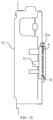
- the deflector is located on a lower side of the heat exchanger and configured to collect condensed water dripped from the heat exchanger.
- a projection of a heat sink in a vertical direction falls inside of the deflector.
- the heat exchange body is at least partially located in the mounting cavity, a bottom wall of the box body is provided with a water outlet, the deflector is located in the mounting cavity and provided to incline relative to the bottom wall of the box body, and the condensed water is guided by the deflector and discharged out of the box body through the water outlet.
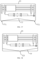
- a height of the deflector along a vertical direction gradually decreases from a middle area of the deflector to each of two ends, so that the condensed water dripped on the deflector flows to the two ends of the deflector.
- the box body is provided with a first water outlet and a second water outlet that respectively correspond to the two ends of the deflector, to discharge the condensed water flowing to the two ends of the deflector.
- the height of the deflector along the vertical direction gradually increases in the direction from the middle area of the deflector to each of two ends, so that the condensed water dripped on the deflector flows to the middle area of the deflector.
- the box body is provided with a water outlet corresponding to the middle area of the deflector, to discharge the condensed water flowing to the middle area of the deflector.
- the electric control box further includes a mounting plate, the mounting plate is located in the mounting cavity, so that the mounting cavity forms a first cavity and a second cavity located on two sides of the mounting plate; and the deflector is connected to the mounting plate or the box body.
- the electric control box further includes a pipeline and a drainage sleeve
- the pipeline is configured to connect the heat exchanger, so as to provide the refrigerant flow for the heat exchanger
- the drainage sleeve is sleeved on the pipeline and configured for drainage of the condensed water flowing through the pipeline.
- the drainage sleeve includes a sleeve body and a flange.
- An insertion opening and a drainage channel are located on the sleeve body, and the insertion opening is configured to set the pipeline.
- the flange is located on an end face of the sleeve body and located on a periphery of the insertion hole.
- the flange is matched with the sleeve body to form a water collecting groove, and the water collecting groove is configured to collect the condensed water of the pipeline.
- the drainage channel is communicated with the water collecting groove and configured to discharge the condensed water in the water collecting groove.
- the heat exchange body is provided with a plurality of first microchannels configured to allow a first refrigerant flow to flow, and a plurality of second microchannels configured to allow a second refrigerant flow to flow.
- the second refrigerant flow absorbs heat from the first refrigerant flow so as to enable the first refrigerant flow to be subcooled, or the first refrigerant flow absorbs heat from the second refrigerant flow so as to enable the second refrigerant flow to be subcooled.
- a second aspect of the present disclosure provides an air conditioning system including the electric control box of any one of above embodiments.
- the electric control box of the present disclosure includes the box body, the electronic component and the heat exchanger, the electronic component is located in the mounting cavity of the box body, and the heat exchanger is configured to dissipate heat of the electronic component, so as to raise the reliability of electric control box.
- the deflector on the lower side of the heat exchanger, the condensed water dripped from the heat exchanger is collected. By adopting this mode, not only can the dripping height of the condensed water be reduced to avoid sputtering of the condensed water drops, but also the deflector has a certain accumulation effect on the condensed water. The condensed water is discharged together after being converged, so that the condensed water is convenient to collect, and the short circuit of electronic components is avoided.
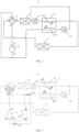
- FIG. 1 is a schematic block view of some embodiments of an air conditioning system of the present disclosure.
- the air conditioning system 1 mainly includes a compressor 2, a four-way valve 3, an outdoor heat exchanger 4, an indoor heat exchanger 5, a heat exchanger 6, an expansion valve 12 and an expansion valve 13.
- the expansion valve 13 and the heat exchanger 6 are disposed between the outdoor heat exchanger 4 and the indoor heat exchanger 5, and the compressor 2 is configured to provide a circulating refrigerant flow between the outdoor heat exchanger 4 and the indoor heat exchanger 5 through the four-way valve 3.
- the heat exchanger 6 includes a first heat exchange passage 610 and a second heat exchange passage 611.
- a first end of the first heat exchange passage 610 is connected to the outdoor heat exchanger 4 through the expansion valve 13, and a second end of the first heat exchange passage 610 is connected to the indoor heat exchanger 5.
- a first end of the second heat exchange passage 611 is connected to the second end of the first heat exchange passage 610 through the expansion valve 12, and the second end of the second heat exchange passage 611 is connected to a suction port 22 of the compressor 2.
- the path of the refrigerant flow is as follows.
- the path (main path) of the refrigerant flow of the first heat exchange passage 610 is: the first end of the first heat exchange passage 610 - the second end of the first heat exchange passage 610 - the indoor heat exchanger 5.
- the path (auxiliary path) of the refrigerant flow of the second heat exchange passage 611 is: the second end of the first heat exchange passage 610 - the expansion valve 12- the first end of the second heat exchange passage 611- the second end of the second heat exchange passage 611- the suction port 22 of the compressor 2.
- the operating principle of the air conditioning system at this time is: the outdoor heat exchanger 4 is used as the condenser, which outputs a medium pressure and medium temperature refrigerant flow (temperature can be 40 degrees Celsius, liquid phase refrigerant flow) through expansion valve 13.
- the refrigerant flow of the first heat exchange passage 610 is the medium pressure and medium temperature refrigerant flow
- the expansion valve 12 converts the medium pressure and medium temperature refrigerant flow into a low pressure and low temperature refrigerant flow (temperature can be 10 degrees Celsius, gas-liquid two-phase refrigerant flow)
- the refrigerant flow of the second heat exchange passage 611 is the low pressure and low temperature refrigerant flow.
- the low pressure and low temperature refrigerant flow of the second heat exchange passage 611 absorbs heat from the medium pressure and medium temperature refrigerant flow of the first heat exchange passage 610, so that the refrigerant flow of the second heat exchange passage 611 is vaporized, to further subcool the refrigerant flow of the first heat exchange passage 610.
- the refrigerant flow of the second heat exchange passage 611 after gasification, increases the enthalpy of compressor 2 by injecting air, thereby improving the refrigeration capacity of air conditioning system 1.
- the expansion valve 12 serves as a throttling part of the second heat exchange passage 611, to adjust a flow rate of the refrigerant flow in the second heat exchange passage 611.
- the refrigerant flow of the first heat exchange passage 610 and the refrigerant flow of the second heat exchange passage 611 are subjected to heat exchange, so as to realize subcooling of the refrigerant flow of the first heat exchange passage 610. Therefore, the heat exchanger 6 can be used as an economizer of the air conditioning system 1, the subcooling degree is improved, and the heat exchange efficiency of the air conditioning system 1 is further improved.
- the connecting port 31 of the four-way valve 3 is connected to the connecting port 33, and the connecting port 32 of the four-way valve 3 is connected to the connecting port 34.
- the refrigerant flow that is outputted from the compressor 2 through the exhaust port 21 flows from the indoor heat exchanger 5 to the outdoor heat exchanger 4, and the indoor heat exchanger 5 is used as the condenser.
- the refrigerant flow outputted by the indoor heat exchanger 5 is divided into two paths, one path flows into the first heat exchange passage 610 (main path), and the other path flows into the second heat exchange passage 611 (auxiliary path) through the expansion valve 12.
- the refrigerant flow of the second heat exchange passage 611 can also subcool the refrigerant flow of the first heat exchange passage 610, so that the heating capacity of the air conditioner is improved.
- the first end of the second heat exchange passage 611 may not be connected to the second end of the first heat exchange passage 610, the first end of the second heat exchange passage 611 can be directly connected to the first end of the expansion valve 13 or the second end of the expansion valve 13, so that the refrigerant flow of the first heat exchange passage 610 can be subcooled by the refrigerant flow of the second heat exchange passage 611, thereby improving the refrigeration or heating capacity of the air conditioning system 1.
- FIG. 4 is a schematic block view of some embodiments of the air conditioning system of the present disclosure.
- the difference between the air conditioning system 1 shown in FIG. 4 and the air conditioning system 1 shown in FIG. 1 is mainly that a gas-liquid separator 8 is added.
- the heat exchanger 6 includes the first heat exchange passage 610 through which the first refrigerant flows and a second heat exchange passage 611 through which the second refrigerant flows.
- the second refrigerant flow absorbs heat from the first refrigerant flow during the flow process along the second heat exchange passage 611, to cause the first refrigerant flow to be subcooled.
- the first refrigerant flow can also absorb heat from the second refrigerant flow during the flow process along the first heat exchange passage 610, to cause the second refrigerant flow to be subcooled. Therefore, the heat exchanger 6 can serve as the economizer for the air conditioning system 1, improving subcooling and thereby improving the heat exchange efficiency of the air conditioning system 1.
- the suction port of the compressor 2 includes an enthalpy-increasing inlet 221 and a return port 222.
- the second refrigerant flow flowing through the second heat exchange passage 611 is further supplied to the enthalpy-increasing inlet 221 of the compressor 2 or the inlet 81 of the gas-liquid separator 8.
- the outlet 82 of the gas-liquid separator 8 is further connected to the return port 222 of the compressor 2 for supplying a low-pressure gaseous refrigerant flow to the compressor 2.
- the air conditioning system 1 also includes the four-way valve 3, the expansion valve 12, and the expansion valve 13.
- the expansion valve 13 and the heat exchanger 6 are disposed between the outdoor heat exchanger 4 and the indoor heat exchanger 5, and the compressor 2 provides the circulating refrigerant flow between the outdoor heat exchanger 4 and the indoor heat exchanger 5 through the four-way valve 3.
- the four-way valve 3 includes the connecting port 31, the connecting port 32, the connecting port 33 and the connecting port 34.
- the connecting port 32 of the four-way valve 3 is connected to the outdoor heat exchanger 4, and the connecting port 34 of the four-way valve 3 is connected to the gas-liquid separator 8.
- the connecting port 31 of the four-way valve 3 is connected to the compressor 2, in some embodiments, the connecting port 31 of the four-way valve 3 is connected to the exhaust port 21 of the compressor 2.
- the connecting port 33 of the four-way valve 3 is connected to the indoor heat exchanger 5.
- the four-way valve 31 in the air conditioning system 1 is configured to realize the mutual conversion between refrigeration and heating by changing the flowing direction of refrigerant flow in the system pipeline, so that the air conditioning system 1 can be switched between a refrigeration mode and a heating mode.
- the four-way valve 31 can be configured to reverse.
- the air conditioning system 1 may also not use the four-way valve 31.
- the compressor 2 can be directly connected to the outdoor heat exchanger 4 through a connecting pipeline.
- the compressor 2 provides the circulating refrigerant flow between the outdoor heat exchanger 4 and the indoor heat exchanger 5 through the connecting pipeline.
- the heat exchanger 6 is disposed between the outdoor heat exchanger 4 and the indoor heat exchanger 5, and is communicated with the connecting pipeline.
- the air conditioning system 1 when the air conditioning system 1 only has refrigeration capacity or heating capacity, the air conditioning system 1 does not use the four-way valve 31, so that the structure of the air conditioning system 1 can be simplified, and the production cost of the air conditioning system 1 is saved.
- the heat exchanger 6 when the heat exchanger 6 is not used as the economizer, the heat exchanger 6 can be communicated with the connecting pipelines at other positions.
- the first end of the first heat exchange passage 610 is connected to the outdoor heat exchanger 4 through the expansion valve 13, the second end of the first heat exchange passage 610 is connected to the indoor heat exchanger 5.
- the first end of the second heat exchange passage 611 is connected to the second end of the first heat exchange passage 610 through the expansion valve 12.
- the second end of the second heat exchange passage 611 is connected to the enthalpy-increasing inlet 221 of the compressor 2 or the inlet 81 of the gas-liquid separator 8.
- the gaseous refrigerant capable of providing intermediate pressure for jet enthalpy increasing of the compressor 2 is provided, thereby improving the refrigeration and/or heating capacity of the air conditioning system 1.
- the principle and effect of jet enthalpy increasing belongs to the understanding range of a skilled person in this field, and not described in this disclosure.
- the air conditioning system 1 may also include a switching assembly.
- the switching assembly is configured to selectively connect the second end of the second heat exchange passage 611 to the enthalpy-increasing inlet 221 of the compressor 2 and the inlet 81 of the gas-liquid separator 8. That is, the switching assembly can be configured to selectively convey the second refrigerant flow flowing through the second heat exchange passage 611 to the enthalpy-increasing inlet 221 of the compressor 2 and the inlet 81 of the gas-liquid separator 8.
- the switching assembly may include a solenoid valve 15.
- the solenoid valve 15 is connected between the enthalpy-increasing inlet 221 of the compressor 2 and the second end of the second heat exchange passage 611, so that the solenoid valve 15 is opened when the compressor 2 requires jet enthalpy increasing, thereby providing the gaseous refrigerant that provides the intermediate pressure for the jet enthalpy increasing of the compressor 2.
- the switching assembly may further include a solenoid valve 14, and the solenoid valve 14 is connected between the second end of the second heat exchange passage 611 and the inlet 81 of the gas-liquid separator 8.
- the solenoid valve 14 is configured to be opened when the compressor 2 does not require or is not suitable for jet enthalpy increasing, thereby guiding the second refrigerant flow output from the second end of the second heat exchange passage 611 into the gas-liquid separator 8.
- the solenoid valve 15 and the solenoid valve 14 are respectively connected to the second end of the second heat exchange passage 612.
- the expansion valve 12 serves as the throttling part of the second heat exchange passage 611, to adjust the flow rate of the second refrigerant flow of the second heat exchange passage 611.
- the refrigeration and heating principles of the air conditioning system 1 shown in FIG. 4 are substantially consistent with the refrigeration and heating principles of the air conditioning system 1 shown in FIG. 1 , and will not be described further herein.
- the air conditioning system 1 also includes an electric control box 7.
- the heat exchanger 6 is connected to the electric control box 7, and the heat exchanger 6 is configured to dissipate heat of electronic components in the electric control box 7, see the description below for details.
- the heat exchanger 6 serves as the economizer of the air conditioning system 1 to improve the degree of subcooling, serves as a heat sink to dissipate heat of the electric control box 7, and dissipates heat of the electronic components in the electric control box 7.
- the present disclosure further optimizes the following aspects 1 to 11 on the basis of the overall structure of the air conditioning system 1 described above.
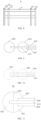
- the heat exchanger 6 includes a heat exchange body 61, and the heat exchange body 61 is provided with a plurality of microchannels 612.
- the plurality of microchannels 612 includes a first microchannel and a second microchannel.
- the first microchannel serves as the first heat exchange passage 610 of the heat exchanger 6
- the second microchannel serves as the second heat exchange passage 611 of the heat exchanger 6.
- the first microchannel 610 and the first heat exchange passage 610 use the same reference numeral
- the second microchannel 611 and the second heat exchange passage 611 use the same reference numeral.
- the heat exchange body 61 may include a single or multiple plate bodies 613.
- each microchannel 612 perpendicular to the extending direction of the microchannel 612 may be rectangular.
- Each microchannel 612 has a side length of 0.5 mm to 3 mm.
- the thickness between each microchannel 612 and the surface of the plate body 613 and the thickness between the microchannels 612 ranges from 0.2 mm to 0.5 mm, so that the microchannels 612 meet the requirements of pressure and heat transfer performance.
- the cross-sectional shape of the microchannels 612 may be other shapes, such as circular, triangular, trapezoidal, elliptical, or irregular.
- the plurality of microchannels 612 may be configured as a single layer microchannel or a multilayer microchannel.
- the plurality of microchannels 612 of the plate body 613 may include the first microchannels 610 and the second microchannels 611 alternately arranged.
- the extending direction D1 of the first microchannel 610 and the extending direction D2 of the second microchannel 611 are parallel to each other.
- the microchannels of a first preset quantity in the plurality of microchannels 612 are divided into the first microchannels 610
- the microchannels of a second preset quantity in the plurality of microchannels 612 are divided into the second microchannels 611
- multiple groups of first microchannels 610 and multiple groups of second microchannels 611 are alternately arranged in sequence.
- the second microchannel 611 is disposed between the two groups of first microchannels 610, and the first microchannel 610 is disposed between the two groups of second microchannels 611, so that the at least two groups of first microchannels 610 and the second microchannels 611 are arranged at intervals.
- the heat exchanger 6 with alternating arrangement of the first microchannel 610 and the second microchannel 611 is formed.
- the first preset quantity and the second preset quantity can be equal or unequal.
- the first microchannel 610 and the second microchannel 611 may be independent of each other, for different refrigerant flows to flow, further, one of the refrigerant flows may be used to subcool the other refrigerant flow.
- the first microchannel 610 and the second microchannel 611 may communicate with each other and used as a microchannel to allow the same refrigerant flow to flow.
- first microchannel 610 and/or the second microchannel 611 when the first microchannel 610 and/or the second microchannel 611 are disposed in two or more layers, the first microchannel 610 and/or the second microchannel 611 in the two or more layers can be communicated with each other through a reverse collecting tube, or the plate body 613 is bent by 180 degrees to form the first microchannel 610 and/or the second microchannel 611 in the two or more layers.
- the heat exchange body 61 may include at least one group of first microchannels 610 and at least one group of second microchannels 611.
- the at least one group of first microchannels 610 and the at least one group of second microchannels 611 are spaced apart from each other in a width direction of the plate body 613, and the width direction of the plate body 613 is perpendicular to the extending direction of the plate body 613.
- the at least one group of first microchannels 610 and the at least one group of second microchannels 611 may also be spaced apart from each other in a thickness direction of the plate body 613, and the thickness direction of the plate body 613 is perpendicular to the extending direction of the plate body 613.
- the first microchannel 610 and the second microchannel 611 are independent of each other, and are respectively disposed in different plate bodies 613, such that the extending direction D1 of the first microchannel 610 and the extending direction D2 of the second microchannel 611 are perpendicular to each other.
- the first collecting tube and the second collecting tube described below can be respectively disposed on different side surfaces of the heat exchanger 6, thereby facilitating the arrangement of the collecting tubes of the heat exchanger 6.
- the first microchannel 610 and the second microchannel 611 are used for different refrigerant flows to flow, so that one refrigerant flow can be used for subcooling the other refrigerant flow.
- the plate body 613 may be a flat tube, such that a heat dissipation component or an electronic component may be disposed on the plate body 613.
- the plate body 613 can also be a carrier with other cross-sectional shapes, such as cylinders, cuboids, cubes, and the like.
- the heat exchange body 61 may also include at least two plate bodies 613 stacked on each other or two tubes nested on each other.
- the first refrigerant flow (i.e., the medium pressure and medium temperature refrigerant flow) flows through the first microchannel 610
- the second refrigerant flow (i.e., the low pressure and low temperature refrigerant flow) flows through the second microchannel 611
- the first refrigerant flow can be the liquid phase refrigerant flow
- the second refrigerant flow can be the gas-liquid two-phase refrigerant flow
- the second refrigerant flow absorbs heat from the first refrigerant flow of the first microchannel 610 during flowing along the second microchannel 611 and is further gasified, so that the first refrigerant flow is further subcooled.
- microchannel structure-based heat exchanger 6 described above and below is not limited to the application scenarios shown in FIGS. 1 to 4 , thus, "first" and “second” of the first microchannel 610, the second microchannel 611, the first refrigerant flow and the second refrigerant flow are merely used to distinguish between different microchannels and refrigerant flows, it should not be construed as limiting the particular application of the microchannel 612 and refrigerant flow.
- the first refrigerant flow that flows through the first microchannel 610 may absorb heat from the second refrigerant flow of the second microchannel 611, and the states of the first refrigerant flow and the second refrigerant flow are not limited to liquid phase or gas-liquid two-phase as defined above.
- the flowing direction A1 of the first refrigerant flow is opposite to the flowing direction A2 of the second refrigerant flow, so that a large temperature difference always exists between the temperature of the first refrigerant flow and the temperature of the second refrigerant flow in the heat exchange area, and the heat exchange efficiency of the first refrigerant flow and the second refrigerant flow is improved.
- the flowing direction A1 of the first refrigerant flow can be the same as or perpendicular to the flowing direction A2 of the second refrigerant flow.
- the temperature of the heat exchanger 6 on the side close to the inlet is lower, so that the heat exchange effect of the area is improved.
- the area is connected to the area with larger electric control heating to improve the heat dissipation effect.
- the heat exchanger 6 further includes a collecting tube assembly 62.
- the extending direction of the collecting tube assembly 62 is perpendicular to the extending direction of the heat exchange body 61.
- the collecting tube assembly 62 is disposed vertically in the direction of gravity, so that when the collecting tube assembly 62 is connected to the compressor disposed below the heat exchanger 6, the pipeline arrangement of the collecting tube assembly 62 may be facilitated.
- the collecting tube assembly 62 is disposed along the horizontal plane, so that the distribution uniformity of the refrigerant in the collecting tube assembly 62 can be improved, and the refrigerant in the heat exchange body 6 can be uniformly distributed.
- the collecting tube assembly 62 includes a first collecting tube 621 and a second collecting tube 622, the first collecting tube 621 is provided with a first collecting passage, and the second collecting tube 622 is provided with a second collecting passage.
- the cross-sectional shape of the heat exchanger 6 in the flowing direction of the refrigerant flow (the first refrigerant flow or the second refrigerant flow) in the heat exchange body 61 is I-shaped.
- the cross-sectional shape of the heat exchanger 6 in the flowing direction of the refrigerant flow in the heat exchange body 61 can be L-shaped, U-shaped, G-shaped, circular, etc.
- the first collecting tube is connected to the first microchannel 610, so as to provide the first refrigerant flow to the first microchannel 610 through the first collecting passage and/or collect the first refrigerant flow flowing through the first microchannel 610.
- a first end of the first microchannel 610 is connected to the outdoor heat exchanger 4 through the expansion valve 13 and one of two first collecting tubes 621, so as to provide the first refrigerant flow to the first microchannel 610 in a refrigeration mode.
- the second end of the first microchannel 610 is connected to the indoor heat exchanger 5 through the other of the two first collecting tubes 621, so as to collect the first refrigerant flow flowing through the first microchannel 610.
- the heating mode since the flowing direction of the first refrigerant flow in the first microchannel 610 is opposite, the functions of the two first collecting tubes 621 are exchanged with respect to the refrigeration mode.
- the second collecting passage is connected to the second microchannel 611, so as to provide the second refrigerant flow and/or collect the second refrigerant flow flowing through the second collecting passage to the second microchannel 611.
- the first end of the second microchannel 611 is connected to the second expansion valve 12 through one of the two second collecting tubes 622, so as to provide the second refrigerant flow to the second microchannel 611.
- the second end of the second microchannel 611 is connected to the enthalpy-increasing inlet 221 of the compressor 2 or the inlet 81 of the gas-liquid separator 8 through the other of the two second collecting tubes 622, so as to collect the second refrigerant flow flowing through the second microchannel 611.
- first microchannel 610 and/or the second microchannel 611 are in communication by 180 ° bending or reverse collecting tube to form two layers of the first microchannel 610 or the second microchannel 611.
- the inlet and the outlet of the first microchannel 610 and/or the second microchannel 611 may be disposed on the same side of the heat exchange body 61, and the first collecting passage and the second collecting passage may be divided into a refrigerant providing area and a refrigerant collecting area.
- the inlet and the outlet of the first and/or second microchannels are respectively connected to the refrigerant area and the refrigerant collecting area provided by the collecting tube assembly 62.
- the heat exchange body 61 includes at least two groups of first microchannels 610 and at least two groups of second microchannels 611.
- the same ends of the at least two groups of first microchannels 610 are connected to the same first collecting tube 621, and the same ends of the at least two groups of second microchannels 611 are connected to the same second collecting tube 622. That is, one collecting tube can correspond to a plurality of groups of microchannels, so that corresponding collecting tubes are prevented from being disposed on each microchannel, and the cost is reduced.
- the extending directions of the first collecting tube 621 and the second collecting tube 622 are parallel to each other.
- the extending directions of the first collecting tube 621 and the second collecting tube 622 may be adjusted in accordance with the extending directions of the first microchannel 610 and the second microchannel 611, such as, perpendicular to each other.
- First collecting tube and second collecting tube are spaced apart from each other
- the first collecting tube 621 and the second collecting tube 622 are spaced apart from each other, and the second collecting tube 622 is further away from the heat exchange body 61 than the first collecting tube 621.
- the first collecting tube 621 is disposed between the second collecting tube 622 and the heat exchange body 61.
- the second microchannel 611 is inserted into the second collecting tube 622 through the first collecting tube 621 and welded.
- the first microchannel 610 is inserted into the first collecting tube 621 and fixed by welding.
- the first collecting tube 621 is disposed farther away from the heat exchange body 61 than the second collecting tube 622, and the second collecting tube 622 is disposed between the first collecting tube 621 and the heat exchange body 61.
- the first microchannel 610 passes through the second collecting tube 622, and is inserted into the first collecting tube 621 and fixed by welding.
- the microchannel passing through the collecting tube described here and in other positions of this disclosure refers to the microchannel passing through the collecting tube and not being connected to the collecting tube.
- the microchannel inserted into the collecting tube refers to the microchannel being connected to the collecting tube.
- the second microchannel 611 passing through the first collecting tube 621 refers to the second microchannel 611 passing through the first collecting tube 621 and not being connected to the first collecting tube 621.
- the second microchannel 611 inserting into the second collecting tube 622 refers to the second microchannel 611 being connected to the second collecting tube 622.
- the first microchannel 610 and the second microchannel 611 may be provided in one or more groups, respectively.
- the first microchannel 610 may be provided in two groups
- the second microchannel 611 may be provided in a group
- the second microchannel 611 is located between the two groups of first microchannels 610.
- the first microchannel 610 and the second microchannel 611 can be disposed into two or more groups, and the first microchannel 610 and the second microchannel 611 are alternately overlapped with each other.
- the first microchannel 610 - the second microchannel 611 - the first microchannel 610 - the second microchannel 611, or the first microchannel 610 - the second microchannel 611 - the second microchannel 611 - the first microchannel 610, and the like are formed.
- one of the first microchannel 610 and the second microchannel 611 may serve as a main passage.
- the other of the first microchannel 610 and the second microchannel 611 serves as an auxiliary passage, and the refrigerant flow in the auxiliary passage is utilized to subcool the refrigerant flow in the main passage. Because the flow rate of the refrigerant flow in the main passage is large, the flow rate of the refrigerant flow in the auxiliary passage is small, the main passage can be provided outside of the heat exchange body 61, which is easy to connect to the electric control box 6 for dissipating the heat of the electric control box 6.
- the main passage with large refrigerant flow passes through the collecting tube corresponding to the auxiliary passage, and inserted into the collecting tube corresponding to main passage.
- the flow path pressure loss of the collecting tube corresponding to main passage can be reduced, so that the flow distribution more uniform.
- the first microchannel 610 when the first microchannel 610 is the main passage with a large refrigerant flow, and the second microchannel 611 is the auxiliary passage with small refrigerant flow, the first microchannel 610 passes through the second collecting tube 622 and is inserted into the first collecting tube 621, so that the second microchannel 611 does not occupy the space of the first collecting tube 621.
- the flow path pressure loss of the first collecting tube 621 can be reduced, and the flow distribution is more uniform.
- first collecting tube 621 and the second collecting tube 622 may be welded together to reduce the distance between the first collecting tube 621 and the second collecting tube 622. In some embodiments, the first collecting tube 621 and the second collecting tube 622 may be bonded or snapped together.
- first microchannel 610 may be connected to the first collecting tube 621 after bypassing the second collecting tube 622.
- first microchannel 610 is disposed outside of the second collecting tube 622 to be connected to the first collecting tube 621 after bypassing the second collecting tube 622, or the second microchannel 611 may be connected to the second collecting tube 622 after bypassing the first collecting tube 621.
- the microchannels on the heat exchange body 61 may also be provided in other ways. At least part of the microchannels passes through one of the at least two collecting tubes, and inserted into another collecting tube. By this way, the volume of the heat exchanger 6 can reduced. In specific arrangement, the microchannel with large refrigerant flow rate passes through one collecting tube of the at least two collecting tube, and inserted into another collecting tube. By this way, the pressure loss of the collecting tube can be smaller, and the flow distribution of the microchannel is more uniform.
- the heat exchange body 61 may be one plate body 613, or composed of a plurality of plate bodies 613. Accordingly, the first microchannel 610 and the second microchannel 611 may be disposed in the same plate body 613, may also be provided in different plate bodies 613. In some embodiments, when the first microchannel 610 and the second microchannel 611 are disposed in the same plate body 613, one end of a part of the microchannels passes through one of the at least two collecting tubes and is inserted into the other collecting tube, and the other end of the at least part of the microchannels is inserted into the collecting tube through which the microchannel passes. Due to this arrangement, the integration level of the heat exchange body 61 can be improved, procedures such as welding and the like can be omitted, and the heat exchange effect is improved.
- the at least two collecting tubes are not limited to the spacing apart from each other as described above, and may be at least two collecting tubes formed by the combination of the main collecting tube and the baffle plate as described below.
- the collecting tube assembly 62 includes a main collecting tube 623 and a baffle plate 624 disposed within the main collecting tube 623, so as to divide the main collecting tube 623 into a first collecting tube 621 and a second collecting tube 622 by the baffle plate 624.
- the baffle plate 624 and the number of collecting tubes can be set according to need.
- the first microchannel 610 passes through the wall of the main collecting tube 623 and is inserted into the first collecting tube 621
- the second microchannel 611 passes through the tube wall of the main collecting tube 623 and the baffle plate 624 (i.e., passing through the first collecting tube 621), and into the second collecting tube 622.
- the second microchannel 611 passes through the wall of the main collecting tube 623 and is inserted into the second collecting tube 622
- the first microchannel 610 passes through the wall of the main collecting tube 623 and the baffle plate 624 and is inserted into the first collecting tube 621.
- the present embodiment achieves the functions of both the first collecting tube 621 and the second collecting tube 622 by one main collecting tube 623, which reduces the cost and volume of the collecting tube assembly 62.
- the main collecting tube 623 may be divided into two first collecting tubes 621 or two second collecting tubes 622 by the baffle plate 624.
- the first microchannel 610 or the second microchannel 611 form two layers of the first microchannel 610 or the second microchannel 611 by 180° bending or the reverse collecting tube
- one end of the first microchannel 610 passes through the wall of the main collecting tube 623 and is inserted into one of the first collecting tubes 621
- the other end of the first microchannel 610 passes through the wall of the main collecting tube 623 and the baffle plate 624 and is inserted into the other first collecting tube 621 of the first collecting tubes 621.
- one end of the second microchannel 611 passes through the wall of the main collecting tube 623 and is inserted into one of the second collecting tubes 622, and the other end of the second microchannel 611 passes through the wall of the main collecting tube 623 and the baffle plate 624 and is inserted into the other second collecting tube 622 of the second collecting tubes 622.
- a slot 601 may be provided on an end face of the heat exchange body 61.
- the slot 601 is located between the first microchannel 610 and the second microchannel 611, and the baffle plate 624 is embedded in the slot 601, such that the first microchannel 610 passes through the wall of the main collecting tube 623 and is inserted into the first collecting tube 621, and the second microchannel 611 passes through the wall of the main collecting tube 623 and is inserted into the second collecting tube 622.
- the inlet end and the outlet end of the heat exchange body 61 are located on the same side.
- one end of the first microchannel 610 passes through the wall of the main collecting tube 623 and is inserted into one of the first collecting tubes 621
- the other end of the first microchannel 610 passes through the wall of the main collecting tube 623 and is inserted into the other one of the first collecting tubes 621.
- one end of the second microchannel 611 passes through the wall of the main collecting tube 623 and is inserted into one of the second collecting tubes 622, and the other end of the second microchannel 611 passes through the wall of the main collecting tube 623 and is inserted into the other of the second collecting tubes 622.
- the heat exchange body 61 may be a single plate body 613 or a plurality of plate bodies 613. In the embodiment shown in FIG. 12 , the heat exchange body 61 may be a single plate body 613. The first microchannel 610 and the second microchannel 611 are disposed within the single plate body 613. Further, on the end face of the single plate body 613, a spacing area is disposed between the first microchannel 610 and the second microchannel 61, and the slot 601 is disposed within the spacing area. In this manner, the heat exchange body 61 is integrated and has a simple structure and high reliability, and the heat transfer efficiency of the heat exchange body 61 can be improved.
- the heat exchange body 61 may also include at least two plate bodies 613, and the at least two plate bodies 613 are stacked, the end faces of the at least two plate bodies 613 are provided with the slots 601, the slots 601 are disposed between adjacent plate bodies 613, and the baffle plate 624 is embedded in the slots 601.
- the combination of the baffle plate 624 and the slot 601 described above can be adapted for other microchannel grouping modes. As long as at least two groups of microchannels are disposed on the heat exchange body 61, the at least two groups of microchannels can be connected to each other for the flow of the same refrigerant flow, or independent of each other for the flow of different refrigerant flows.
- the diameter of the second collecting tube 622 is smaller than the diameter of the first collecting tube 621, and the first collecting tube 621 is sleeved on the outer side of the second collecting tube 622.
- the first microchannel 610 passes through the wall of the first collecting tube 621 and is inserted into the first collecting tube 621.
- the second microchannel 611 passes through the walls of the first collecting tube 621 and the second collecting tube 622, and is inserted into the second collecting tube 622.
- the second collecting tube 622 is sleeved on the outer side of the first collecting tube 621, at this time, the second microchannel 611 passes through the wall of the second collecting tube 622 and is inserted into the second collecting tube 622.
- the first microchannel 610 passes through the walls of the second collecting tube 622 and the first collecting tube 621, and is inserted into the first collecting tube 621.
- the volume of the collecting tube assembly 62 can be reduced by nesting settings.
- the two first collecting tubes 621 may be nested with each other, or the two second collecting tubes 622 may be nested with each other.
- one end of the first microchannel 610 passes through the wall of the first collecting tube 621 on the outer side, and is inserted into the first collecting tube 621 on the outer side.
- the other end of the first microchannel 610 passes through the walls of the two first collecting tubes 621, and is inserted into the first collecting tube 621 on the inner side.
- one end of the second microchannel 611 passes through the wall of the second collecting tube 622 on the outer side, and is inserted into the second collecting tube 622 on the outer side.
- the other end of the second microchannel 611 passes through the walls of the two second collecting tubes 622, and is inserted into the first collecting tube 622 on the inner side.
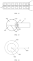
- the heat exchanger 6 includes the heat exchange body 61, and the heat exchange body 61 includes a first tube body 614 and a second tube body 615 nested with each other. That is, the heat exchanger 6 is a double-tube heat exchanger, the plurality of first microchannels 610 are disposed in the first tube body 614, the plurality of second microchannels 611 are disposed in the second tube body 615.
- the plurality of first microchannels 610 and the plurality of second microchannels 611 are the same as the microchannels 612 shown in FIG. 5 , so that the length of the heat exchange body 61 is shortened, and the volume of the heat exchanger 6 is further reduced.
- the extending direction of the first microchannel 610 and the extending direction of the second microchannel 611 are parallel to each other, In some embodiments, the extending direction of the first microchannel 610 is the same as the extending direction of the second microchannel 611.
- the first tube body 614 is sleeved on the outer side of the second tube body 615, and at least one plane 616 is disposed on the outer surface of the first tube body 614 to form a heat exchange contact surface of the first tube body 614.
- the heat dissipation component or the electronic component can be disposed on the plane 616 to be convenient to install.
- the second tube body 615 can be sleeved on the outer side of the first tube body 614 to form a similar plane.
- the first refrigerant flow flows through the plurality of first microchannels 610, and the second refrigerant flow flows through the plurality of second microchannels 611.
- the first refrigerant flow may be a liquid phase refrigerant flow
- the second refrigerant flow may be a gas-liquid two-phase refrigerant flow.
- the second refrigerant flow absorbs heat from the first refrigerant flow of the plurality of first microchannels 610 during flowing along the plurality of second microchannels 611, and is further gasified, such that the first refrigerant flow is further subcooled.
- the first refrigerant flow flowing through the first microchannel 610 may absorb heat from the second refrigerant flow flowing through the second microchannel 611, and the states of the first refrigerant flow and the second refrigerant flow are not limited to liquid phase or gas-liquid phases as defined above.
- the cross-sectional area of the heat exchange body 61 is enlarged, so that the pressure loss of refrigerant flow can be reduced.
- the first pipe body 614 and the second pipe body 615 are sleeved, so that the heat exchanging area of the first microchannels 610 and the second microchannels 611 can be increased, and the heat exchanging efficiency between the first microchannels 610 and the second microchannels 611 can be improved.
- the heat exchanger 6 also includes the collecting tube assembly 62, and the collecting tube assembly 62 includes the first collecting tube 621 and the second collecting tube 622.
- the first collecting tube 621 is provided with the first collecting passage, and the first collecting passage is configured to provide the first refrigerant flow to the first microchannel 610 and/or collect the first refrigerant flow flowing through the first microchannel 610.
- the second collecting tube 622 is provided with the second collecting passage, and the second collecting tube provides the second refrigerant flow to the second microchannel 611 and/or collects the second refrigerant flow flowing through the second microchannel 611.
- the cross-sectional shape of the heat exchanger 6 along the flowing direction of the refrigerant flow in the heat exchange body 61 may be L-shaped, U-shaped, G-shaped or circular, etc.
- the collecting tube assembly 62 may adopt the various collecting tube arrangements described above, such as, the setting mode that the first collecting tube 621 and the second collecting tube 622 described above are spaced apart from each other, the setting mode of the main collecting tube 623 and the baffle plate 624, or the setting mode that the first collecting tube 621 and the second collecting tube 622 may be nested with each other.
- the first tube body 614 together with the first microchannel 610 thereon, and the second tube body 615 together with the second microchannel 611 thereon may cooperate with the collecting tube in the manner described above, which will not be described further herein.
- Heat exchanger has a plurality of plate bodies stacked on each other
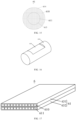
- the heat exchanger 6 includes the heat exchange body 61, and the heat exchange body 61 includes a first plate body 631 and a second plate body 632 which are stacked on each other.
- the plurality of first microchannels 610 are disposed in the first plate body 631, and the plurality of second microchannels 611 are disposed in the second plate body 632.
- the plurality of first microchannels 610 and the plurality of second microchannels 611 are identical to the microchannels 612 shown in FIGS. 5-7 and will not be described further herein.
- a multi-layer structure is adopted, so that the length of the heat exchange body 61 is shortened, and the volume of the heat exchanger 6 is further reduced.
- the contact area between the first plate body 631 and the second plate body 632 is increased, so that the heat exchange area between the first microchannel 610 and the second microchannel 611 is increased, and the heat exchange efficiency is improved.
- the first refrigerant flow flows through the plurality of first microchannels 610
- the second refrigerant flow flows through the plurality of second microchannels 611
- the second refrigerant flow absorbs heat from the first refrigerant flow of the plurality of first microchannels 610 during flowing along the plurality of second microchannels 611 and is further gasified, so that the first refrigerant flow is further subcooled.
- the first refrigerant flow flowing through the first microchannel 610 may absorb heat from the second refrigerant flow flowing through the second microchannel 611, and the states of the first refrigerant flow and the second refrigerant flow are not limited to liquid phase or gas-liquid phases as defined above.
- the first plate body 631 and the second plate body 632 may be respectively provided with one or more.
- the number of the first plate bodies 631 may be two, and the second plate body 632 is sandwiched between the two first plate bodies 631.
- the first plate body 631, the second plate body 632 and the first plate body 631 are sequentially stacked.
- the second plate body 632 is sandwiched between the two first plate bodies 631, so that the second refrigerant flow of the second plate body 632 simultaneously absorbs heat from the first refrigerant flows of the two first plate body 631, to subcool the first refrigerant flows of the two first plate bodies 631.
- the heat dissipating component or the electronic component may be thermally connected to the first plate body 631, such as disposed on a surface of the first plate body 631 away from the second plate body 632, to facilitate mounting.
- the first plate body 631 and the second plate body 632 may be provided, and the first plate body 631 and the second plate body 632 may be alternately stacked.
- the two first plate bodies 631 can be two mutually independent plate bodies. In some embodiments, the two first plate bodies 631 can also be integrally connected in a U shape or connected through the reverse collecting tube. At this time, the first microchannels 610 in the two first plate bodies 631 are communicated in a U shape, so that the inlets and the outlets of the first microchannels 610 are located on the same side of the heat exchange body 61.
- the number of second plate bodies 632 may be two, and the first plate body 631 is sandwiched between the two second plate bodies 632. At the same time, the heat dissipation component or the electronic component may be thermally connected to the second plate body 632.
- the heat exchanger 6 also includes the collecting tube assembly 62, the collecting tube assembly 62 includes the first collecting tube 621 and the second collecting tube 622.
- the first collecting tube 621 is provided with the first collecting passage, and the first collecting tube is configured to provide the first refrigerant flow to the first microchannel 610 and/or collect the first refrigerant flow flowing through the first microchannel 610.
- the second collecting tube 622 is provided with the second collecting tube, and the second collecting tube 622 provides the second refrigerant flow to the second microchannel 611 and/or collects the second refrigerant flow flowing through the second microchannel 611.
- the collecting tube assembly 62 may adopt the various collecting tube arrangements described above, such as, the setting mode that the first collecting tube 621 and the second collecting tube 622, described above, are spaced apart from each other, the setting mode of the main collecting tube 623 and the baffle plate 624, or the setting mode that the first collecting tube 621 and the second collecting tube 622 may be nested with each other.
- the first plate body 631 together with the first microchannel 610 thereon, and the second plate 633 together with the second microchannel 611 thereon, may cooperate with the collecting tube in the manner described above.
- the heat exchanger 6 includes the first plate body 631, the second plate body 632 and a connecting sheet 64.
- the first plate body 631 and the second plate body 632 are mutually overlapped, and the connecting sheet 64 is clamped between the adjacent first plate body 631 and the adjacent second plate body 632.
- the solders (not shown) are disposed on two sides of the connecting sheet 64, and the solders are used for fixedly welding the connecting sheet 64 with the first plate body 631 and the second plate body 632 on two sides of the connecting sheet 64.
- the solders are disposed on two sides of the connecting sheet 64, and then the first plate body 631 and the second plate body 632 are welded by the connecting sheet 64. In this manner, the first plate body 631 and the second plate body 632 can be effectively fixed.
- the solder is required to be coated on the bonding surfaces of the two plate bodies 613 when the adjacent plate bodies 613 are welded, compared with the plate bodies 613 with the surfaces coated with the solder, the production cost can be greatly reduced by arranging the connecting sheet 64 with the solder between the two plate bodies 613.
- the connecting sheet 64 having a melting point higher than the melting point of the solder can be a metal foil, to improve thermal conductivity.
- the connecting sheet 64 can be an aluminum foil or a copper foil or the like, which is relatively low in cost. The process of arranging the solder on two sides of the metal foil is relatively simple. Therefore, the metal foil with the solder is relatively easy to obtain and has relatively low production cost.
- the coverage area of the solder on the connecting sheet 64 to the adjacent first plate body 631 and second plate body 632 on two adjacent sides shall not be less than 80% of the overlapping area of the first plate body 631 and second plate body 632, thereby improving the reliability of welding between the first plate body 631 and the second plate body 632.
- the coverage area of the solder on the connecting sheet 64 to the first plate body 631 and the second plate body 632 may be 80% of the overlapping area of the first plate body 631 and the second plate body 632 on two adjacent sides; or, the coverage area of the solder on the connecting sheet 64 to the adjacent first plate body 631 and second plate body 632 on two adjacent sides is equal to the overlapping area of the first plate body 631 and second plate body 632, in this way, the reliability of the heat exchanger 6 may be further improved.
- the connecting sheet 64 between the first plate body 631 and the second plate body 632 may be of a single layer structure, that is, only one layer of connecting sheet 64 is provided between the first plate body 631 and the second plate body 632.
- the connecting pieces 64 between the first plate body 631 and the second plate body 632 are at least two layers, In some embodiments, the connecting sheet 64 may be a two-layer, three-layer, or four-layer structure or the like. The at least two layers of connecting sheet 64 are further fixed by solder welding. By flexibly selecting the number of layers of the connecting sheet 64, the distance between the first plate body 631 and the second plate body 632 can be adjusted, thereby enabling heat exchanger 6 to adapt to different application scenarios. In some embodiments, forming a slot between the first plate body 631 and the second plate body 632, the slot has a width equal to the laminated thickness of the at least two layers of connecting sheet 64, to cooperate with the baffle plate described above.
- the thickness of the connecting sheet 64 may range from 0.9 mm to 1.2 mm. In some embodiments, the thickness of the connecting sheet 64 may be 0.9 mm, 1 mm, or 1.2 mm, etc.
- the connecting sheet 64 may be disposed between other adjacent plate bodies of at least two plate bodies having microchannels, such as two first plate bodies 631, or two second plate bodies 632.
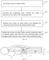
- the method of making the heat exchanger 6 described above may include: S11: providing at least two plate bodies; S12: providing the connecting sheet, wherein the solder is disposed on two sides of the connecting sheet; S13: stacking the at least two plate bodies, and clamping the connecting sheet between the adjacent plate bodies; S14: heating the at least two plate bodies and the connecting sheet, so that the solder welds and fixes the connecting sheet with the plate bodies that are on two sides of the connecting sheet.
- the heat exchanger 6 includes at least two plate bodies 613 and at least one collecting tube 620, wherein each plate body 613 includes a body part 671 and a connecting part 672.
- the body parts 671 of the at least two plate bodies 613 are stacked on each other, one end of the connecting part 672 is connected to the body part 671, and the other end of the connecting part 672 is connected to the collecting tube 620.
- the collecting tube 620 has at least two insertion holes 602 formed in the wall of the collecting tube 620.
- the other end of the connecting part 672 of the plate body 613 corresponds to the insertion hole 602 and is welded and fixed on the collecting tube 620. That is, the connecting part 672 is located at the end of the plate body 613 and is configured to fix with the collecting tube 620.
- the at least two plate bodies 613 are welded with the collecting tube pipe 620, if the spacing distance between the two adjacent plate bodies 613 is small at the welding position, the welding difficulty is increased, solder can flow along a gap between the two adjacent plate bodies 613, thereby causing poor welding between the plate bodies 613 and the collecting tube 620, and the risk of refrigerant flow leakage.
- a first spacing d1 is between two adjacent insertion holes 602 on the collecting tube 620
- a second spacing d2 is between the body parts 671 of two adjacent plate bodies 613
- the first spacing d1 is greater than the second spacing d2.
- the first spacing d1 is not less than 2mm, in some embodiments, the first spacing d1 can be 2mm or 3mm and the like, so that the capillary action between the connecting parts 672 of the plate body 613 is reduced, and the welding between the connecting parts 672 of the plate body 613 and the collecting tube 620 is facilitated. Furthermore, the first spacing d1 is not greater than 6mm, so that the heat exchanger 6 has higher structural strength, and the reliability of the heat exchanger 6 is improved.
- the connecting parts 672 of at least part of the plate bodies 613 are bent, and disposed in an arc shape, so that the distance between the connecting parts 672 of the two adjacent plate bodies 613 can be adjusted conveniently through the bent arrangement mode, the plate bodies 613 and the collecting tube 620 can be welded and fixed conveniently, and the capillary action between the two adjacent plate bodies 613 during welding can be reduced.
- one end of the connecting part 672 of the plate body 613 is bent and the other end is disposed in a straight line to simplify the machining process.
- a third spacing d3 is formed between the connecting parts 672 of at least partially adjacent plate bodies 613.
- the third spacing d3 gradually increases in at least partial range from the body part 671 to the collecting tube 620, so that the distance between the adjacent connecting parts 672 gradually increases and the capillary action between two adjacent plate bodies 613 is reduced.
- the at least two plate bodies 61 may include the first plate body 631 and the second plate body 632 as described above.
- the number of the first plate bodies 631 is two
- the number of the second plate bodies 632 is two
- the first plate body 631 and the second plate body 632 are stacked in this order.
- the second plate body 632 is sandwiched between the two first plate bodies 631, and the other second plate body 632 is overlapped on the outer side of one first plate bodies 631, that is away from the second plate body 632, sandwiched between the two first plate bodies 631.
- the collecting tube 620 includes the first collecting tube 621 and the second collecting tube 622 that are spaced apart from each other.
- the first plate body 631 is provided with a plurality of first microchannels that is configured to allow the first refrigerant flow to flow.
- the second plate body 632 is provided with a plurality of second microchannels that is configured to allow the second refrigerant flow to flow.
- the second refrigerant flow absorbs heat from the first refrigerant flow during flowing along the plurality of second microchannels 611, so that the first refrigerant flow is subcooled.
- the first refrigerant flow absorbs heat from the second refrigerant flow during flowing along the plurality of first microchannels 610, so that the second refrigerant flow is subcooled.
- the connecting part 672 of the first plate body 631 is fixedly welded with the first collecting tube 621
- the connecting part 672 of the second plate body 632 is fixedly welded with the second collecting tube 621.
- the connecting part 672 of the clamped second plate body 632 can pass through the first collecting tube 621, and is connected to the second collecting tube 622.
- the connecting part 672 of the second plate body 632 located on the outer side can bypass the first collecting tube 621 and be welded to the second collecting tube 622. In this way, the number of the insertion holes 602 on the first collecting tube 621 can be reduced, the distance between the insertion holes 602 is increased, and the assembly of the heat exchanger 6 is facilitated, so that the heat exchanger 6 has higher reliability, and the interference to the refrigerant flow in the first collecting tube 621 can be reduced.
- the connecting parts 672 of the second plate bodies 632 pass through the first collecting tube 621 and are connected to the second collecting tube 622. In some embodiments, the connecting part 672 of the first plate body 631 may pass through the second collecting tube 622 and be connected to the first collecting tube 621, which will not be described further herein.
- the number of the first plate body 631 and the number of the second plate body 632 can be selected according to practical application requirements and are not limited specifically.
- the collecting tube 620 may also adopt the various collecting tube arrangements, described above, and will not be described further herein.
- the body parts 672 of the plate body 613 have a linear structure, so that the body part 671 of the first plate body 631 and the body part 671 of the second plate body 632 can be directly welded by solder.
- the body part 671 of the first plate body 631 is connected to the body part 671 of the second plate body 672, through the connecting sheet with the solder described above, which will not be described further herein.
- the heat exchanger 6 includes the heat exchange body 61 and a plurality of heat dissipation fins 65.
- the heat dissipation fins 65 can be disposed on the heat exchange body 61 and are in heat conduction connection with the heat exchange body 61, so that the contact area of the heat exchange body 61 and the air is enlarged by utilizing the heat dissipation fins 65, the heat exchange with the air is facilitated.
- the heat exchange efficiency of the heat exchanger 6 is improved, and the radiating effect of the heat exchanger 6 is improved.
- the heat dissipation fins 65 can be connected to the surface of the heat exchange body 61 by welding, bonding or fastening.
- the heat exchange body 61 includes at least two plate body assemblies 603 juxtaposed and spaced apart from each other, and the heat dissipation fins 65 are disposed on the at least two plate body assemblies 603.
- the heat exchanger 6 also includes a fixing plate 66.
- the fixing plate 66 simultaneously covers the heat dissipation fins 65 on the at least two plate body assemblies 603, and the fixing plate 66 is located on a side of the heat dissipation fins 65 away from the plate body assembly 603, so that a heat dissipation duct is formed.
- the sealing of the heat dissipation fins 65 adopts an integral fixing plate 66 structure with fewer components, making the production of heat exchanger 6 simple and reliable.
- the formed heat dissipation duct can improve the heat dissipation effect.
- the airflow direction defined by the heat dissipation duct can be set along the interval direction of the plate body component, that is perpendicular to the extending direction of the plate body assembly 603, to increase the heat dissipation efficiency of the heat dissipation fins 65.
- the airflow direction defined by the heat dissipation duct may be along the extending direction of the plate body assembly 603 or at other angles to the extending direction of the plate body assembly 603.
- the fixing plate 66 includes a top panel 661, and the top panel 661 simultaneously covers the heat dissipation fins 65 of the at least two plate body assemblies 603 to facilitate sealing of the heat dissipation fins 65.
- the fixing plate 66 further includes at least one side panel 662.
- the side panel 662 is connected to the top panel 661 in a bending mode and extends towards the plate body component 603 to seal the heat dissipation duct through the side panel 662, so that the components of the heat exchanger 6 are reduced, and the sealing performance of the heat dissipation duct is improved.
- the fixing plate 66 may include the top panel 661 and the side panel 662.
- the side panel 662 is connected to one end of the top panel surface 661 in the bending mode.
- One end of the heat dissipation fin 65 abuts against the side panel 662 to seal the heat dissipation duct, and the other end of the heat dissipation fin 65 can be spliced and assembled through other parts, or abuts against the box body of the electric control box described below, so as to enable the heat dissipation fin 65 to form a complete air duct. In this way, the packaging of the heat dissipation fin 65 can be simplified, and the assembling efficiency can be improved.
- the number of the side panels 662 is two, two side panels 662 are spaced apart from each other in a direction perpendicular to the spacing direction of the at least two plate body assemblies 603.
- the top panel 661 is respectively connected to the two side panels 662 in the bending mode to form an accommodating space, and the heat dissipation fins 65 are located in the accommodating space, that is between the two side panels 662.
- the fixing plate 66 can completely seal the heat dissipation fins 65 to form an integral heat dissipation duct, so that the number of parts is small, the packaging process of the heat dissipation fins 65 is further simplified.
- the production of the heat exchanger 6 is simple and reliable, and meanwhile, the heat exchange capacity is improved.
- the heat dissipation fins 65 are wave structures formed by sheet extrusion, and the wave crests and troughs of the wave structures are respectively in contact with the surfaces of the top panel 661 and the plate body assembly 603 opposite to each other.
- the number of heat dissipation fins 65 may be at least two. As shown in FIG. 25 , the number of heat dissipation fins 65 may be equal to the number of plate body assemblies 603, and each heat dissipation fin 65 is disposed on the corresponding plate body assembly 603. The width of each heat dissipation fin 65 in the vertical direction along the extending direction of the plate body assembly 603 can be equal to the width of the corresponding plate body component 603, so as to improve heat transfer capacity and save material costs.
- each heat dissipation fin 65 may be attached to one plate body assembly 603.
- a plurality of heat dissipation fins 65 may be spaced apart from each other along a spacing direction of the plate body assembly 603.
- the temperature of the gap between the plate bodies 613 is higher than that of the plate bodies 613, so that the heat dissipation fins 65 can be prevented from being melted and deformed through this setting mode.
- the heat dissipation fins 65 are spaced apart from each other, so that the heat exchange efficiency of the heat dissipation fins 65 can be ensured, the material can be saved, and the production cost can be reduced.
- the number of the heat dissipation fins 65 can also be one. That is, the heat dissipation fins 65 are integrally disposed, and disposed on at least two plate body assemblies 603. At the same time, the width of the heat dissipation fins 65 in the vertical direction along the extending direction of the plate body assembly 603 can be larger than or equal to the width of the heat exchange body 61. Thus, the number of the integrated heat dissipation fins 65 is small and the surface area of the integrated heat dissipation fins 65 is large.
- the heat dissipation fins 65 can be conveniently connected to the heat exchange body 61, and the mounting efficiency of the heat dissipation fins 65 and the heat exchange body 61 is improved.
- the contact area between the heat dissipation fins 65 and the air can be enlarged to enhance the heat exchange effect.
- the fixing plates 66 are open setting at two ends in the spacing direction of the at least two plate body assemblies 603, so that the flowing direction of the air flow in the heat dissipation duct is further disposed along the spacing direction of the at least two plate body assemblies 603.
- the flowing direction of the refrigerant flow in the plate body assemblies 603 is perpendicular to the spacing direction of the at least two plate body assemblies 603, so that the heat dissipation effect of the heat dissipation duct is enhanced, and the overall heat exchange efficiency of the heat exchanger 6 is improved.
- Each plate body assembly 603 may be provided with the microchannel, such as, using various plate-to-microchannel configurations described above, which will not be described further herein.
- heat dissipation fin 65 is applicable to the various forms of heat exchanger 6 described herein and should not be limited to a specific embodiment.
- Heat exchanger serves as heat sink
- the heat exchanger 6 described above may also be used as a heat sink (described below as heat sink 6).
- the heat sink 6 includes the heat exchange body 61 and the collecting tube assembly 62.
- the heat sink 6 is configured to dissipate heat from the electronic components within the electric control box 7.
- the heat sink 6 referred to herein should include the various forms of heat exchanger described above, and should not be limited to a specific embodiment.
- the heat sink 6 is used as the economizer of the air conditioning system 1 and simultaneously replaces a module heat sink in the electric control box 6 for radiating the electric control box 7, so that the number of pipeline components and modules of the air conditioning system 1 is simplified, and the cost is lowered.
- the electric control box 7 includes a box body 72 and the heat sink 6, the box body 72 is provided with a mounting cavity 721.
- An electronic component 71 is disposed in the mounting cavity 721
- the heat sink 6 is disposed in the mounting cavity 721 and is configured to dissipate the heat of the electronic component 71 in the mounting cavity 721.
- the heat sink 6 can also be disposed outside of the box body 72 and is configured to dissipate the heat of the electronic component 71 in the mounting cavity 721.
- the box body 72 includes a top plate (not shown, opposite to a bottom plate 723, and covering the opening of the mounting cavity 721), the bottom plate 723 and a circumferential side plate 724.
- the top plate and the bottom plate 723 are opposite to and spaced apart from each other.
- the circumferential side plate 724 is connected to the top plate and the bottom plate 723, thereby forming the mounting cavity 721.
- the bottom plate 723 and the top plate are rectangular.
- the number of circumferential side plates 724 is four, the four circumferential side plates 724 are connected to corresponding sides of the bottom plate 723 and the top plate, respectively, further forming a cuboid electric control box 7 by enclosing the four circumferential side plates 724, the bottom plate 723 and the top plate.
- the length of long side of the bottom plate 723 is the length of the electric control box 7
- the length of the short side of the bottom plate 723 is the width of the electric control box 7
- the height of the circumferential side plate 724 perpendicular to the bottom plate 723 is the height of the electric control box 7. As shown in FIG.
- the length of the electric control box 7 in the X direction is the length of the electric control box 7
- the length of the electric control box 7 in the Y direction is the height of the electric control box 7
- the length of the electric control box 7 in the Z direction is the width of the electric control box 7.
- the heat exchange body 61 is disposed in a straight strip shape, as shown in FIG. 18 , the heat exchange body 61 has an overall length, an overall width, and an overall height.
- the overall length is the length of the heat exchange body 61 along its extending direction, that is, the length of the heat exchange body 61 along the X direction shown in FIG. 18 .
- the overall width is the length of the heat exchange body 61 in the direction perpendicular to the extending direction of the heat exchange body 61 and perpendicular to the plane where the heat exchange body 61 is located, that is, the length of the heat exchange body 61 along the Y direction shown in FIG. 18 .
- the overall height is the length of the heat exchange body 61 along the Z direction shown in FIG. 18 .
- the plane where the heat exchange body 61 is located refers to the plane where the collecting tube assembly 62 is located, which is the XOZ plane shown in FIG. 18 .
- the heat exchange body 61 may be disposed on the bottom plate 723 of the electric control box 7 or may be disposed on the circumferential side plate 724 of the electric control box 7. In some embodiments, the heat exchange body 61 may also be fixed on other positions of the electric control box 7 according to the setting position of the electronic component 71.
- the embodiments of the present disclosure are not specifically limited.
- the heat exchange body 61 When the heat exchange body 61 is in the shape of the straight strip as shown in FIG. 18 , the heat exchange body 61 may be abutted against the bottom plate 723, or the heat exchange body 61 and the bottom plate 723 are spaced apart from each other, so that the size of the bottom plate 723 in the length direction can be fully utilized.
- the heat exchange body 61 as long as possible is disposed to improve the heat exchange effect.
- the heat exchange body 61 can also be abutted against the circumferential side plate 724, or the heat exchange body 61 and the circumferential side plate 724 are spaced apart from each other, and the embodiment of the present disclosure is not specifically limited.
- the heat exchange body 61 may be divided into a first extension part 617 and a second extension part 618.
- the second extension part 618 is connected to the end of the first extension part 617 and bent toward one side of the first extension part 617, so that the heat exchange body 61 is L-shaped.
- the overall length of the heat exchange body 61 can be reduced under the condition of ensuring that the heat exchange body 61 has enough extension length, so that the length of the electric control box 7 matched with the heat sink 6 along the X direction can be reduced, and the volume of the electric control box 7 can be reduced.
- the first extension part 617 may be disposed parallel to the bottom plate 723 to fully utilize the size of the length direction of the bottom plate 723, and the heat exchange body 61 may be disposed as long as possible to enhance the heat exchange effect.
- the second extension part 618 may be disposed parallel to the circumferential side plate 724 to reduce the space occupied by the second extension part 618 in the x-direction.
- first extension part 617 may be parallel to one of the circumferential side plates 724
- second extension part 618 may be parallel to one circumferential side plate 724 adjacent to the circumferential side plate 724, to dispose the heat sink 6 on one of the sides of the mounting cavity 721.
- the first extension part 617 may be abutted against the bottom plate 723, or may be spaced apart from the bottom plate 723.
- the second extension part 618 may be abutted against the circumferential side plate 724, or may be spaced apart from the circumferential side plate 724, and the embodiments of the present disclosure are not specifically limited.
- the number of second extension part 618 may be one, and the second extension part 618 is attached to one end of the first extension part 617 such that the heat exchange body 61 is L-shaped.
- the number of second extension part 618 may be two.
- the two second extension parts 618 are respectively connected to two opposite ends of the first extension parts 617, and respectively bent toward the same side of the first extension part 617.
- two second extension parts 618 may be spaced apart from each other and parallel at two opposite ends of the first extension parts 617, thereby reducing the overall length of heat exchange body 61 and the volume of heat sink 6 while ensuring the heat exchange effect of heat exchange body 61.
- the two second extension parts 618 are located on the same side of the first extension part 617 in a bending mode, so that the overall width of the heat sink 6 can be conveniently shortened.
- the two second extending parts 618 can be perpendicularly to the first extending parts 617 to form the U-shaped heat exchange body 61, so that not only can the overall length of the heat exchange body 61 be reduced, but also the occupied space of the second extending parts 618 in the X direction can be reduced, and the interference between the two second extending parts 618 and the electronic component 71 in the mounting cavity 721 can be avoided.
- the two second extension parts 618 may be tilted with respect to the first extension part 617.
- the angles of inclination of the two second extension parts 618 with respect to the first extension part 617 may be the same or different to reduce the overall width of the electric control box 7.
- the extending length of the first extension part 617 is larger than that of the second extension part 618, so that the first extension part 617 is disposed along the length direction of the electric control box 7, and the second extension part 618 is disposed along the width or height direction of the electric control box 7.
- the number of heat sinks 6 disposed in the mounting cavity 721 may be one, one heat sink 6 may located in the mounting cavity 721 and extend along the length direction of the box body 72, or one heat sink 6 may located in the mounting cavity 721 and extend along the height direction of the box body 72.
- the number of the heat sinks 6 disposed in the mounting cavity 721 can be at least two. In some embodiments, the number of the heat sinks 6 can be two, three, four or five, and the heat dissipation effect of the electric control box 7 can be improved by arranging a large number of the heat sinks 6.
- Heat sink is disposed inside of electric control box
- heat sink 6 may also be disposed within the mounting cavity 721 of the electric control box 7 or applied to the heat dissipation of the electric control box 7, and may be thermally connected to the electronic component 71 in a direct or indirect manner.
- the heat sink 6 is disposed in the mounting cavity 721 of the electric control box 7.
- the heat sink 6 may be thermally connected to the electronic component 71 disposed in the mounting cavity 721 for heat dissipation of the electronic component 71.
- the electronic component 71 can be thermally connected to the heat exchange body 61, and can be thermally connected to any position of the heat exchange body 61.
- the electronic component 71 can be disposed at any position on the heat exchange body 61. In this manner, the assembly of electronic components 71 is facilitated. In some embodiments, the electronic component 71 can be disposed in the middle position of the heat exchange body 61 or can be disposed at two ends of the heat exchange body 61. The electronic component 71 can be disposed on one side of the heat exchange body 61 or can be disposed on two opposite sides of the heat exchange body 61, according to practical application scenarios.
- the electronic component 71 when the heat sink 6 is L-shaped or U-shaped, the electronic component 71 may be thermally connected to the first extension part 617, and the electronic component 71 and the second extension part 618 may be disposed on the same side of the first extension part 617 to reduce the height of the electric control box 7, that is, the dimension in the Y direction.
- the electronic component 71 may be thermally connected to the second extension part 618, and in some embodiments, the electronic component 71 may be disposed on the side of the second extension part 618 facing the first extension part 617 to shorten the length of the electric control box 7, that is, the dimension in the X direction.
- the electronic component 71 may be partially disposed on the first extension part 617 and partially disposed on the second extension part 618, such that the electronic component 71 is uniformly distributed.
- a heat dissipation fixing plate 74 can also be disposed in the electric control box 7.
- the electronic component 71 is disposed on the heat dissipation fixing plate 74, and then the heat dissipation fixing plate 74 is connected to the heat exchange body 61, so that the electronic component 71 and the heat exchange body 61 are in heat conduction connection through the heat dissipation fixing plate 74. Therefore, the mounting efficiency of the electronic component 71 can be greatly improved.
- the heat dissipation fixing plate 74 can be made of a metal plate or an alloy plate with good heat conduction performance. In some embodiments, the heat dissipation fixing plate 74 can be made of an aluminum plate, a copper plate, an aluminum alloy plate and the like to improve the heat conduction efficiency.
- a heat pipe 741 can be embedded in the heat dissipation fixing plate 74.
- the heat pipe 741 is configured to rapidly conduct and diffuse the concentrated high-density heat source to the surface of the whole heat dissipation fixing plate 74, so that the heat on the heat dissipation fixing plate 74 is uniformly distributed, and the heat exchange effect of the heat dissipation fixing plate 74 and the heat exchange body 61 is enhanced.
- the heat pipes 741 can be a long strip shape, the number of the heat pipes 741 can be multiple, the heat pipes 741 can be parallel to and spaced apart from each other. In some embodiments, as shown in the figure on the lower side of FIG. 31 , the heat pipes 741 can be sequentially connected to form an annular shape or a frame shape. The embodiment of the present disclosure is not specifically limited.
- Heat sink is disposed outside of electric control box
- the heat sink 6 is disposed outside of the electric control box 7, an assembly port 726 can be disposed on the box body 72 of the electric control box 7, and the electronic component 71 is thermally connected to the heat sink 6 through the assembly port 726.
- the electronic component 71 is disposed on a side surface of the heat sink fixing plate 74 away from the heat sink 6.
- the heat pipes 741 may be provided, so that the electronic component 71 is thermally connected to the heat sink 6.
- the heat pipe 741 may include a heat absorbing end 741a and a heat releasing end 741b.
- the heat absorbing end 741a of the heat pipe 741 may be inserted into the interior of the mounting cavity 721 and thermally connected to the electronic component 71, for absorbing heat from the electronic component 71.
- the heat releasing end 741b of the heat pipe 741 may be disposed outside of the electric control box 7 and thermally connected to the heat sink 6, for dissipating heat from the heat releasing end 741b of the heat pipe 741 through the heat sink 6.
- the heat sink 6 includes the heat dissipation fins 65.
- the contact area of the heat exchange body 61 and the air in the electric control box 7 can be enlarged by utilizing the heat dissipation fins 65, so that the heat exchange with the air is facilitated, the temperature in the mounting cavity 721 is reduced, and the electronic component 71 is protected.
- the electronic component 71 and the heat dissipation fins 65 may be disposed on the same side of the heat exchange body 6, and the electronic component 71 and the heat dissipation fins 65 are disposed in a staggered manner, so that interference between the electronic component 71 and the heat dissipation fins 65 is avoided.
- the distance between the electronic component 71 and the heat dissipation fins 65 is larger, so that the temperature of the refrigerant contacted with the heat dissipation fins 65 and the electronic component 71 is lower, and the dissipating effect of the heat exchange body 61 is improved.
- the electronic component 71 is disposed on one side of the heat exchange body 61, and the heat dissipation fins 65 are disposed on the other side of the heat exchange body 61. In some embodiments, the heat dissipation fins 65 may be disposed at any position on the other side of the heat exchange body 61.
- the heat dissipation fins 65 may extend to the outside of the electric control box 7.
- the box body 72 is provided with the assembly port, the heat exchange body 61 is disposed in the box body 72 and thermally connected to the electronic component 71.
- One side of the heat dissipation fin 65 is thermally connected to the heat exchange body 61 and extends to the outer side of the box body 72 through the assembly port. The dissipating heat capacity of the heat exchange body 61 can be further improved through air cooling assistance.
- Electronic component is disposed at a position where temperature of heat sink is higher
- the electric control box 7 of the present embodiment includes the box body 72 provided with the mounting cavity 721, the heat sink 6 at least partially disposed in the mounting cavity 721, and the electronic component 71 disposed in the mounting cavity 721.
- the structures of the box body 72 and the heat sink 6 are substantially identical to those of the embodiments described above, reference is made to the description of the embodiments described above.
- the heat exchange body 61 may be disposed entirely in the mounting cavity 721 of the electric control box 7, or may be partially disposed in the mounting cavity 721 of the electric control box 7, partially protruding beyond the electric control box 7 for connection with the collecting tube assembly 62 and an external pipeline.
- the flowing of the refrigerant flow causes the temperature of the heat sink 6 to be lower. Because the electronic component 71 in the electric control box 7 generates heat to cause the temperature in the mounting cavity 721 of the electric control box 7 to be higher, when the air with higher temperature in the electric control box 7 is contacted with the heat sink 6, the air is easy to condense, so that the condensed water is formed on the surface of the heat sink 6. When the generated condensed water flows to the position where the electronic component 71 is located, the electronic component 71 is easy to short circuit or damage, and more serious fire hazards can be generated.
- the heat exchange body 61 may be divided into a first end 6A and a second end 61b along the flowing direction of the refrigerant flow.
- the temperature of the heat exchange body 61 is gradually reduced in the direction from the first end 6A to the second end 61b. That is, the temperature of the first end 6A is higher than the temperature of the second end 61b.
- the electronic component 71 is disposed at a position close to the first end 61a, and the electronic component 71 is thermally connected to the heat exchange body 61.
- the temperature of the heat exchange body 61 described above and below refers to the surface temperature of the heat exchange body 61.
- the change of the surface temperature of the heat exchange body 61 is determined by the heat exchange passage adjacent to the surface.
- the heat exchange passage adjacent to the surface of the heat exchange body 61 is the main passage, because the refrigerant flow of the main passage is continuously absorbed by the refrigerant flow of the auxiliary passage, the surface temperature of the heat exchange body 61 gradually decreases along the refrigerant flow direction of the main passage.
- the refrigerant flow direction of the first end 61a along the main passage flows to the upstream located on the second end 61b.
- the heat exchange passage adjacent to the surface of the heat exchange body 61 is the auxiliary passage, the surface temperature of the heat exchange body 61 gradually decreases and increases along the refrigerant flow direction of the auxiliary passage.
- the first end 61a flows to the downstream located on the second end 61b along the refrigerant flow direction of the auxiliary passage.
- the heat exchange body 61 is divided into the first end 6A with higher temperature and the second end 61b with lower temperature. Because the temperature difference between the first end 61a with higher temperature and the hot air is smaller, the condensed water cannot be generated, or the amount of the generated condensed water is smaller.
- the electronic component 71 By disposing the electronic component 71 at the position close to the first end 61a, the contact probability of the electronic component 71 and the condensed water can be reduced, and the electronic component 71 is further protected.
- the temperature of the heat exchange body 61 has an opposite change tendency from the first end 6A to the second end 61b. That is, in one mode, the temperature of the heat exchange body 61 gradually decreases from the first end 61a to the second end 61b, and in another mode, the temperature of the heat exchange body 61 gradually increases from the first end 61a to the second end 61b. In some embodiments, it is preferable to ensure that in the refrigeration mode, the temperature of the heat exchange body 61 gradually decreases from the first end 61a to the second end 61b, for the following reasons.
- the ambient temperature when the ambient temperature is low, in some embodiments, when the air conditioner operates in winter to heat, the temperature of the air in the electric control box 7 is lower. At this time, the temperature difference between the air in the electric control box 7 and the heat sink 6 is small, air is not easy to condense to form the condensed water.
- the ambient temperature when the air conditioner operates in summer for refrigeration, the temperature of the air in the electric control box 7 is higher. Since the temperature difference between the air in the electric control box 7 and the heat sink 6 is large, the air is easy to condense to form the condensed water.
- the temperature of the heat exchange body 61 is gradually reduced in the direction from the first end 61a to the second end 61b, so as to prevent the heat sink 6 from generating the condensed water in the refrigeration mode.
- disposing the electronic component 71 at the position close to the first end 61a means that the electronic component 71 has a first distance between the thermal conductivity connection position on the heat exchange body 61 and the first end 61a, and a second distance between the thermal conductivity connection position on the heat exchange body 61 and the second end 61b.
- the first distance is less than the second distance.
- the temperature of the heat exchange body 61 gradually decreases in the direction from the first end 6a to the second end 61b, the temperature of the first end 6a is the highest, and the temperature of the second end 61b is the lowest.
- the higher the temperature of the heat exchange body 61 the smaller the temperature difference between the heat sink 6 and the air in the electric control box 7, the more difficult the condensed water is to condense.
- the probability of generating condensed water is gradually increased.
- the risk of contact between the electronic component 71 and the condensed water can be reduced by disposing the electronic component 71 close to the higher temperature end of the heat exchange body 61, that is, at the position where the condensed water is not easy to accumulate, thereby protecting the electronic component 71.
- the extending direction of the heat exchange body 61 can be disposed along the vertical direction, and the first end 61a is disposed above the second end 61b, so that when the condensed water is generated at the position of the heat exchange body 61 closed to the second end 61b, the condensed water can flow downwards along the vertical direction. That is, the condensed water can flow towards the direction away from the electronic component 71, and the electronic component 71 is prevented from being contacted with the condensed water.
- the extending direction of the heat exchange body 61 can be disposed along the horizontal direction as required, so that the condensed water generated at the position close to the second end 61b can be quickly separated from the heat exchange body 61 under the action of gravity, thereby avoiding contacting with the electronic component 71.
- the extending direction of the heat exchange body 61 may be tilted with respect to the horizontal direction, and embodiments of the present disclosure are not specifically limited.
- the structure of the heat sink 6 in some embodiments may be the same as in the embodiments described above, that is, a bent heat exchange body 61 is adopted. Or the structure of the heat sink 6 in the present embodiment can also adopt a straight strip-shaped heat exchange body 61. Or beside the heat sink 6 with microchannels described above, other types of heat sinks may also be adopted.
- the embodiments of the present disclosure do not limit the specific structure of the heat sink 6.
- other embodiments of the present disclosure that apply the heat sink to the electric control box may adopt the various heat sinks disclosed herein, or other heat sinks well known in the art.
- the electric control box 7 of the present embodiment includes the box body 72, a mounting plate 76, the electronic component 71, and the heat sink 6.
- the box body 72 is provided with the mounting cavity 721, the mounting plate 76 is disposed in the mounting cavity 721 so that the mounting cavity 721 forms a first cavity 7212 and a second cavity 7214 on two sides of the mounting plate 76.
- the electronic component 71 is disposed in the second cavity 7214, at least a portion of the heat exchange body 61 is disposed in the first cavity 7212 and is thermally connected to the electronic component 71, and the mounting plate 76 is configured to block the condensed water on the heat sink 6 from flowing into the second cavity 7214.
- the electronic component 71 can be completely isolated from the condensed water, so that short circuit or damage of the electronic component 71 caused by contacting with the condensed water can be avoided.
- a heat dissipation fixing plate 74 may be configured to indirectly connect the electronic component 71 to the heat exchange body 61.
- an avoiding hole 762 may be formed in the mounting plate 76 at a position corresponding to the heat dissipation fixing plate 74.
- the heat dissipation fixing plate 74 is connected to the heat exchange body 61 and plugs the avoiding hole 762.
- the electronic component 71 is provided on the side of the heat dissipation fixing plate 74 away from the heat exchange body 61, so that the heat dissipation fixing plate 74 can be configured for thermally connecting the electronic component 71 to the heat exchange body 61.
- the heat dissipation fixing plate 74 can be configured for separating the first cavity 7212 from the second cavity 7214, so as to prevent the condensed water from flowing into the second cavity 7214 provided with the electronic component 71 through the avoiding hole 762, and further prevent the condensed water from contacting with the electronic component 71.
- the condensed water can fall down under the action of gravity after being accumulated, and the dripped condensed water is easy to sputter, so that hidden troubles are brought to circuits in the electric control box 7, and the dispersed condensed water is not favorable for being discharged out of the electric control box 7.
- a deflector 77 can be disposed in the electric control box 7.
- the deflector 77 is disposed below the heat sink 6 and configured for collecting the condensed water dripping from the heat sink 6, so that the dripping height of the condensed water can be reduced, and the sputtering of the condensed water can be avoided.
- the deflector 77 also has a certain accumulation effect on the condensed water, so that the condensed water can be conveniently discharged out of the electric control box 7 after being converged.
- the deflector 77 is fixed on the bottom plate 723 of the electric control box 7.
- One end of the deflector 77 is connected to the bottom plate 723, the other end of the deflector 77 extends into the first cavity 7212.
- the projection of the heat sink 6 along the vertical direction is on the deflector 77, so that condensed water dripping from the heat sink 6 can be located on the deflector 77, and is prevented from dripping to other positions of the electric control box 7.
- the heat sink 6 may also be disposed on the mounting plate 76.
- One end of the deflector 77 is connected to the mounting plate 76, and the other end of the deflector 77 extends into the first cavity 7212. The projection of the heat sink 6 in the vertical direction falls on the deflector 77.
- a water outlet 725 can be formed in the bottom wall of the box body 72.
- the deflector 77 is obliquely disposed relative to the bottom wall of the box body 72, and the condensed water is guided by the deflector 77 and then discharged out of the box body 72 through the water outlet 725.
- the water outlet 725 can be formed in the circumferential side plate 724 of the electric control box 7.
- the deflector 77 is connected to the mounting plate 76 or the bottom plate 723 of the box body 72 and is obliquely disposed in the direction of the water outlet 725. After condensed water drips on the deflector 77, the condensed water can converge to the position of the water outlet 725 along the oblique deflector 77 and then is discharged out of the electric control box 7 through the water outlet 725.
- the number and the size of the water outlet 725 can be flexibly set according to the amount of condensed water, and the embodiment of the present disclosure is not specifically limited.
- the flowing direction of the refrigerant flow in the heat exchange body 61 can be set horizontally. That is, the extending direction of the heat exchange body 61 is disposed along the horizontal direction.
- the flowing path of the condensed water on the heat exchange body 61 can be shortened, so that the condensed water drips on the deflector 77 as soon as possible under the action of gravity, the condensed water can be conveniently discharged out of the electric control box 7 in time, and the condensed water is prevented from being contacted with the electronic component 71 disposed in the mounting cavity 721.
- interference between the deflector 77 and the heat exchange body 61 can be avoided, so that a relatively long heat exchange body 61 can be disposed, and the heat exchange efficiency of the heat sink 6 can be improved.
- the height of the deflector 77 gradually decreases in the vertical direction, so as to make the condensed water dripped on the deflector 77 flow to two ends of the deflector 77. That is, the deflector 77 is disposed in an inverted V shape. In this way, the overall height of the deflector 77 along the vertical direction can be reduced, the interference between the deflector 77 and other parts in the electric control box 7 can be avoided, and the condensed water dripped on the deflector 77 by the heat sink 6 can be quickly discharged.
- the box body 72 is provided with a first water outlet 771 and a second water outlet 772 that correspond to the positions of the two ends of the deflector 77 respectively, so that the condensed water flowing to the two ends of the deflector 77 is discharged.
- the condensed water dripped on the deflector 77 flows to the two ends of the deflector 77, and is discharged out of the box body 72 through the first water outlet 771 and the second water outlet 772.
- the height of the deflector 77 is gradually increased in the vertical direction, so that the condensed water dripping on the deflector 77 flows to the middle area of the deflector 77. That is, the deflector 77 can be disposed in a V shape. In this way, the condensed water can be collected to the middle area of the deflector 77 through the deflector 77 and can be discharged from the middle area.
- the box body 72 is provided with the water outlet 725 corresponding to the position of the middle area of the deflector 77, so as to discharge the condensed water flowing to the middle area of the deflector 77, which facilitates collection and drainage of condensed water.
- the number and the size of the water outlets 725, the first drain outlet 771 and the second drain outlet 772 can be flexibly set according to the amount of condensed water, and the embodiment of the present disclosure is not specifically limited.
- the deflector 77 described above may be disposed below the heat sink 6, wherein the heat sink 6 may be installed in the electric control box 7 in other ways and configured to dissipate heat from the electronic components 71 in the electric control box 7. This disclosure is not limited to the embodiments described above.
- the box body 72 is provided with the mounting cavity 721, and at least a portion of the heat exchange body 61 is disposed in the mounting cavity 721.
- the electronic component 71 is thermally connected to the heat exchange body 61 at a first position.
- the heat dissipation fins 65 are thermally connected to the heat exchange body 61 at a second position. The first position and the second position are spaced apart from each other along the flowing direction of the refrigerant flow of the heat exchange body 61.
- the refrigerant flow referred to herein may be either the main refrigerant flow of the air conditioning system shown in FIGS. 1 to 4 , or the auxiliary refrigerant flow.
- the electronic component 71 and the heat dissipation fins 65 are spaced apart from each other along the flowing direction of the refrigerant flow of the heat exchange body 61, so that the space on the heat exchange body 61 can be fully utilized. Not only the heat exchange body 61 can be utilized to dissipate the heat of the electronic component 71, but also the heat dissipation fins 65 can be utilized to reduce the temperature in the mounting cavity 721 of the electric control box 7, thereby protecting the electronic component 71 disposed in the mounting cavity 721.
- the heat exchange body 61 includes the first end 61a and the second end 61b that are spaced apart from each other in the flowing direction of the refrigerant flow.
- the temperature of the heat exchange body 61 gradually decreases in the direction from the first end 61a to the second end 61b. That is, the temperature of the first end 61a is greater than the temperature of the second end 61b, and the first position is closer to the first end 61a than the second position.
- the temperature of the surface of the heat exchange body 61 varies with the flowing direction of the refrigerant flow, further forming the first end 6A with a higher temperature and the second end 61b with a lower temperature.
- the temperature difference between first end 6A with the higher temperature and the hot air in the mounting cavity 721 is small, it is not easy to generate the condensed water.
- the electronic component 71 may be disposed close to the first end 6A. That is, the first position is close to the first end 6A.
- the temperature difference between the second end 61b with the lower temperature and the hot air in the mounting cavity 721 is large, it is easy to generate the condensed water.
- the heat dissipation fins 65 may be disposed close to the second end 61b.
- the heat dissipation fins 65 with lower temperature can ensure that the temperature difference between the heat dissipation fins 65 and the hot air is large enough, to dissipating heat from the electric control box 7.
- the condensed water formed by condensation on the heat dissipation fins 65 can be evaporated under the action of hot air, and the condensed water is evaporated to absorb heat, so that the temperature of refrigerant flow is further reduced, and the heat exchange effect of the heat sink 6 is improved.
- a cooling fan 78 can also be disposed in the electric control box 7, and the cooling fan 78 is configured to form a heat dissipation airflow acting on the heat dissipation fins 65 in the electric control box 7, so that the flowing speed of the heat dissipation airflow can be accelerated, and the heat exchange effect is further improved.
- the cooling fan 78 may be disposed close to the heat dissipation fins 65 to act directly on the heat dissipation fins 65.
- the mounting plate 76 may also be disposed in the electric control box 7.
- the mounting plate 76 is disposed in the mounting cavity 721, such that the mounting cavity 721 forms the first cavity 7212 and the second cavity 7214 on two sides of the mounting plate 76.
- a first vent 764 and a second vent 766 are formed in the mounting plate 76, and spaced apart from each other, so that the air in the first cavity 7212 flows into the second cavity 7214 through the first vent 764, and the air in the second cavity 7214 flows into the first cavity 7212 through the second vent 766.
- At least part of the heat exchange body 61 is located in the first cavity 7212, and the electronic component 71 and the cooling fan 78 are disposed in the second cavity 7214.
- the mounting cavity 721 is divided into the first cavity 7212 and the second cavity 7214 that are independent of each other by the mounting plate 76.
- the circulating airflow can be formed in the first cavity 7212 and the second cavity 7214 to increase the volume of the air that contact with the heat dissipation fins 65 disposed in the first cavity 7212.
- the cooled airflow can conveniently dissipate the heat of the electronic component 71 disposed in the second cavity 7214, so that the mixed flow of the air is avoided, and the heat dissipation efficiency of the heat dissipation fins 65 is improved.
- the cooling fan 78 disposed in the second cavity 7214 is configured to accelerate the flowing speed of air in the second cavity 7214, so that the circulating speed of the air between the first cavity 7212 and the second cavity 7214 is accelerated, and the heat dissipation efficiency of the electric control box 7 is improved.
- the flowing direction of the heat dissipation airflow that flows through the heat dissipation fins 65 may be perpendicular to the flowing direction of the refrigerant flow.
- the heat dissipation airflow may be configured to flow in the vertical direction to prevent the heat dissipation airflow from flowing to the position where the electronic component 71 is located.
- first vent 764 and the second vent 766 may be vertically spaced apart from each other on two opposite sides of the heat dissipation fin 65, and the number and arrangement density of the first vent 764 and the second vent 766 may be set according to need.
- the heat dissipation airflow when the refrigerant flow in the heat exchange body 61 is in the vertical direction, the heat dissipation airflow can be set to flow in the horizontal direction to prevent the heat dissipation airflow from flowing to the position where the electronic component 71 is located.
- the flowing direction of the heat dissipation airflow and the flowing direction of the refrigerant flow can also be set to be in the other two mutually perpendicular directions, the embodiments of the present disclosure are not specifically limited.
- first vent 764 and the second vent 766 are vertically disposed, the first vent 764 may be disposed above the second vent 766, such that the hot air entering the first cavity 7212 through the second vent 766 automatically rises to the position where the heat exchange body 61 is located, and exchanges heat with the heat exchange body 61.
- the cooling fan 78 may be close to the first vent 764 to facilitate timely entry of the cold air at the top of the first cavity 7212 into the second cavity 7214, and the cooling fan 78 may accelerate the cold air to enhance the heat dissipation efficiency of the electronic component 71.
- the box body 72 of the electric control box 7 is generally provided with the heat dissipation holes communicated with the mounting cavity 721, to naturally convection heat with the external air through the heat dissipation holes, thereby cooling the electric control box 7.
- the sealing performance of the electric control box 7 is reduced by disposing the heat dissipation holes on the box body 72, so that impurities such as outside moisture and dust can enter the mounting cavity 721 through the heat dissipation holes, and further electronic components disposed in the mounting cavity 721 are damaged.
- the box body 72 of the electric control box 7 can be disposed into a sealing structure, and specifically, as shown in FIG. 41 , the electric control box 7 includes the box body 72, the mounting plate 76, the heat sink 6, the electronic component 71 and the cooling fan 78.
- the box body 72 is provided with the mounting cavity 721, and the mounting plate 76 is disposed in the mounting cavity 721, such that the mounting cavity 721 forms the first cavity 7212 and the second cavity 7214 on two sides of the mounting plate 76.
- the mounting plate 76 is provided with the first vent 764 and the second vent 766 spaced apart from each other, and the first vent 764 and the second vent 766 communicate with the first cavity 7212 and the second cavity 7214.
- the heat sink 6 is disposed at least partially in the first cavity 7212.
- the electronic component 71 is disposed in the second cavity 7214 and thermally connected to the heat sink 6.
- the cooling fan 78 is adapted to supply wind, such that air in the first cavity 7212 flows into the second cavity 7214 through the first vent 764.
- the heat sink 6 is disposed at least partially in the first cavity 7212, and the electronic component 71 and the heat dissipation fan 78 are disposed in the second cavity 7214.
- the first vent 764 and the second vent 766 spaced apart from each other and communicating with the first cavity 7212 and the second cavity 7214 are formed in the mounting plate 76.
- the electronic component 71 generates heat to cause the temperature of the air in the second cavity 7214 to be higher.
- the cooling fan 78 supplies the hot air to the second vent 766. Because the density of the hot air is small, the hot air naturally rises to contact with the heat sink 6 disposed in the first cavity 7212.
- the heat sink 6 is used for cooling the hot air to form cold air, and the cold air flows into the second cavity 7214 from the first vent 764.
- the cooling fan 78 is used for accelerating the cold air, so as to cool the electronic component 71 disposed in the second cavity 7214 with cold air.
- the temperature of the cold air after heat exchange with the electronic component 71 is increased.
- the cold air with the increased temperature further continues to enter the second vent 766 under the action of the cooling fan 78.
- the electronic component 71 disposed in the electric control box 7 is cooled in an internal circulation mode.
- the electric control box 7 is a totally-enclosed electric control box 7, so that the problems of water prevention, insect prevention, dust prevention, moisture prevention and the like can be effectively solved, and the electric control reliability of the electric control box 7 is improved.
- the plane where the cooling fan 78 is located is perpendicular to the plane where the mounting plate 76 is located, and the leeward side of the cooling fan 78 is disposed toward the first vent 764.
- the cooling fan 78 may be disposed on one side of the mounting plate 76 facing the second cavity 7214.
- the direction of the rotating shaft of the cooling fan 78 is parallel to the plane where the mounting plate 76 is located.
- the leeward side of the cooling fan 78 refers to the air intake side of the cooling fan 78.
- the cooling fan 78 can be disposed between the first vent 764 and the electronic component 71, and the cold air entering the second cavity 7214 through the first vent 764 flows out after being accelerated by the cooling fan 78, so that the flowing speed of the cold air is increased, and the heat dissipation efficiency of the electric control box 7 is improved.
- the cooling fan 78 may also be configured as a centrifugal fan.
- the centrifugal fan is a mechanical device that relies on input mechanical energy to increase gas pressure and exhaust gas.
- the working principle of the centrifugal fan is to use a high-speed rotating impeller to accelerate the gas. Therefore, in some embodiments, by setting the cooling fan 78 as the centrifugal fan, on one hand, the high-speed cold air can be obtained, and the heat dissipation efficiency of the electronic component 71 can be improved; and on the other hand, the centrifugal fan can simplify the structure of the cooling fan 78 and improve the mounting efficiency.
- the air deflectors may also be spaced apart from each other on the mounting plate 76, and the air guide flow passages may be formed between the air deflectors for guiding the air blown by the cooling fan 78.
- two air deflectors that are parallel to and spaced apart from each other may be provided between the dispersedly disposed electronic components 71.
- the extending directions of the air deflectors are along the spacing direction of the electronic component 71, so that the air guide flow passage along the spacing direction of the electronic component 71 is defined between the two air deflectors.
- the cold air blown by the heat dissipation fan 78 first flows to the position where a part of the electronic component 71 is located, so as to dissipating heat from the electronic component 71.
- the air passing through the part of the electronic component 71 further flows to the position where the other part of the electronic component 71 is located through the air guide flow passage, so as to dissipating heat from the other part of the electronic component 71. Therefore, the heat dissipation of the electronic component 71 is more balanced to avoid damage caused by excessive temperature in local electronic components 71.
- the heat sink 6 canbe disposed in the electric control box 7, that is, the heat exchange body 61 can be disposed in the first cavity 7212 for cooling the air in the first cavity 7212.
- the heat sink 6 can be disposed outside of the electric control box 7, and at least part of the heat sink 6 extend into the first cavity 7212.
- the assembly port (not shown) communicating with the first cavity 7212 may be formed in the box body 72.
- the heat exchange body 61 is connected to the outer side wall of the box body 72, and the heat dissipation fins 65 are connected to the heat exchange body 61 and inserted into the first cavity 7212 through the assembly port.
- the matching mode of the heat sink 6 and the electric control box 7 in some embodiments is the same as the matching mode of the heat sink 6 and the electric control box 7 in the above embodiment. Referring to the description in the above embodiment and will not be repeated here.
- the electronic component 71 may be disposed in the blowing range of the cooling fan 78, so that the cooling fan 78 directly acts on the electronic component 71 to cool the electronic component 71.
- the electronic component 71 may include a primary heating element having a large calorific value, such as a common mode inductor 711, a reactance 712 and a capacitor 713; and a secondary heating element having a small calorific value, such as a fan module 714.
- a primary heating element having a large calorific value such as a common mode inductor 711, a reactance 712 and a capacitor 713
- a secondary heating element having a small calorific value such as a fan module 714.
- the distance between the primary heating element and the first vent 764 may be set to be less than the distance between the secondary heating element and the first vent 764. That is, the primary heating element having the large calorific value can be disposed close to the first vent 764, and the secondary heating element having the small calorific value is disposed away from the first vent 764.
- the lower temperature air entering through the first vent 764 first acts on the primary heating element having the large calorific value, so as to improve the heat diss
- the second vent 766 may be disposed at the end of the blowing of the cooling fan 78, and close to the electronic component 71 with the large calorific value.
- the radiation range of the cooling fan 78 can be enlarged, and the circulation efficiency of air in the second cavity 7214 can be improved.
- the hot air after heat exchange with the electronic component 71, having the large calorific value can be discharged out of the second cavity 7214 in time, so that the temperature of the whole second cavity 7214 is prevented from being increased.
- the second vent 766 can be disposed close to the first vent 764 to shorten the circulation path of air in the second cavity 7214, reduce the air flow resistance, improve the air circulation efficiency, and further improve the heat dissipation efficiency of the electric control box 7.
- first vent 764 and the second vent 766 may also be set according to the arrangement of the electronic components 71.
- the number of second vents 766 may be multiple.
- a plurality of second vents 766 may be disposed at different position on the mounting plate 76, respectively.
- the size of the second vent 766 located at the position of the electronic component 71 having the large calorific value can be relatively larger, and the number of second vents 766 can also be set relatively larger, and the distribution density of multiple second vents 766 can be set relatively larger.
- the size of the second vent 766 located at the position of the electronic component, 71 having the small calorific value can be relatively smaller, and the number of second vents 766 can also be set relatively smaller, and the distribution density of multiple second vents 766 can be set relatively smaller.
- first vent 764 may be greater than that of the second vent 766 to increase return air volume and efficiency of the cooling fan 78.
- the electric control box 7 includes the box body 72, the mounting plate 76, the heat sink 6, and a primary heating element 715.
- the box body 72 is provided with the mounting cavity 721, the mounting plate 76 is disposed in the mounting cavity 721, so that the mounting cavity 721 forms the first cavity 7212 and the second cavity 7214 that are disposed on two sides of the mounting plate 76.
- the mounting plate 76 is provided with the first vent 764 and the second vent 766 that are spaced apart from each other along the vertical direction.
- the heat sink 6 is disposed at least partially in the first cavity 7212.
- the primary heating element 715 is disposed in the second cavity 7214.
- the first vent 764 and the second vent 766 communicate with the first cavity 7212 and the second cavity 7214 to form the circulating heat dissipation airflow between the first cavity 7212 and the second cavity 7214, using the temperature difference between the primary heating element 715 and the heat sink 6.
- the primary heating element 715 is disposed in the second cavity 7214.
- the heat generated by the operation of the primary heating element 715 causes the temperature in the second cavity 7214 to rise. Because the density of the hot air is small, the hot air naturally rises and enters the first cavity 7212 through the first vent 764 in the top of the second cavity 7214. The hot air contacts with the heat sink 6 and exchanges heat with the heat sink 6. The temperature of the hot air is reduced, and the density of the hot air is increased. The hot air naturally sinks to the bottom of the first cavity 7212, under the action of gravity, and enters the second cavity 7214 through the second vent 766 for cooling the primary heating element 715 disposed in the second cavity 7214. After heat exchange with the primary heating element 715, the hot air further rises to the position of the first vent 764, thereby forming an internal circulating air flow between the first cavity 7212 and the second cavity 7214.
- the first vent 764 and the second vent 766 communicating with the first cavity 7212 and the second cavity 7214 are formed in the mounting plate 76, and the first vent 764 and the second vent 766 are disposed in a vertical direction.
- the circulation flow between the first cavity 7212 and the second cavity 7214 is achieved by utilizing the gravity of the air, thereby cooling the electronic component 71 disposed in the second cavity 7214, and reducing the overall temperature of the electric control box 7.
- the structure of the electric control box 7 in the embodiment is more concise, the assembly efficiency of the electric control box 7 can be improved, and the production cost of the electric control box 7 can be reduced.
- the heat sink 6 may be disposed above the primary heating element 715 in the direction of gravity. That is, the heat sink 6 is disposed close to the top of the first cavity 7212, and the primary heating element 715 is disposed close to the bottom of the second cavity 7214. According this arrangement mode, the distance between the heat sink 6 and the first vent 764 can be reduced, so that the hot air entering the first cavity 7212 through the first vent 764 is quickly contacted with the heat sink 6 for cooling, and naturally sinks under the action of gravity. By reducing the distance between the primary heating element 715 and the second vent 766, the hot air entering the second cavity 7214 through the second vent 766 is quickly contacted with the primary heating element 715 to be heated, and naturally rises under the action of buoyancy. Thus, the circulation speed of airflow in the electric control box 7 can be increased, and the heat dissipation efficiency is improved.
- a secondary heating element 716 can be disposed in the electric control box 7.
- the secondary heating element 716 is disposed in the second cavity 7214 and thermally connected to the heat exchange body 61.
- the calorific value of the secondary heating element 716 is smaller than that of the primary heating element 715.
- the primary heating element 715 having a large calorific value may be disposed close to the second vent 766.
- the cold air entering through the first cavity 7212 may be first contacted with the heated electronic component 71, improving the heat dissipation efficiency of the electronic component 71.
- a large temperature difference between the cold air and the electronic component 71 with large calorific value can be realized, so that the cold air can be quickly heated, and then rapidly rises under the action of buoyancy.
- the secondary heating element 716 with small calorific value is disposed on the heat exchange body 61 and contacted with the heat exchange body 61, so that the heat exchange body 61 can be used for directly cooling the electronic component 71 with small calorific value.
- the primary heating element 715 with large calorific value and the secondary heating element 716 with small calorific value are disposed in different areas, so that the electronic component 71 can be reasonably distributed, and the internal space of the electric control box 7 can be fully utilized.
- the secondary heating element 716 is connected to the heat exchange body 61, through the heat dissipation fixing plate 74, to improve the assembly efficiency of the secondary heating element 716.
- connection of the secondary heating element 716 to the heat exchange body 61 may be the same as in the embodiments described above, and will not be described herein with specific reference to the embodiments described above.
- the heat sink 6 may be disposed outside of the electric control box 7 and at least partially extend into the first cavity 7212.
- the matching mode of the heat sink 6 and the electric control box 7 is the same as the matching mode of the heat sink 6 and the electric control box 7 in the embodiments described above, and reference is made to the description of the embodiments described above.
- Drainage sleeve is disposed on pipeline
- the air conditioning system 1 of the present embodiment includes the heat sink 6, pipelines 710, and a drainage sleeve 79.
- the pipelines 710 are configured to connect the heat sink 6, to provide the refrigerant flow to the heat sink 6 or collect the refrigerant flow out of the heat sink 6. In some embodiments, the pipeline 710 is connected to the collecting tube assembly of heat sink 6.
- the pipelines 710 may include an input line and an output line.
- the input line is configured to provide the refrigerant flow to the heat sink 6, and the output line is configured to collect the refrigerant flow in the heat sink 6.
- the drainage sleeve 79 is sleeved on the pipelines 710, and is configured for drainage of the condensed water that is formed on the pipelines 710 or flows through the pipeline.
- the condensed water on the pipelines 710 can be guided by the drainage sleeve 79.
- the drainage sleeve 79 has the function of protecting the pipelines 710, improving the reliability of the air conditioning system 1.
- the drainage sleeve 79 includes a sleeve body 791 and a flange 792.
- the sleeve body 791 is provided with an insertion opening 793 and a drainage channel 708.
- the insertion opening 793 is configured to set the pipelines 710.
- the number and the size of the insertion opening 793 can be set according to the distribution and the size of the pipelines 710. In some embodiments, in the embodiment shown in FIG. 46 , the number of the insertion openings 793 is two. In some embodiments, the number of the insertion opening 793 can be one or three, and the like.
- the sleeve body 791 may be made of a flexible material, such as thermoplastic polyurethane elastomer rubber, so as to protect the pipelines 710, and prevent the pipeline 710 that contact with the electrical control box sheet metal during vibration from being abrased.
- the flange 792 is disposed on the end face of the sleeve body 791, and is located at the periphery of the insertion opening 793, and further is matched with the sleeve body 791 to form a water collecting groove 794.
- the water collecting groove 794 is configured to collect the condensed water on the pipelines 710.
- the drainage channel 708 is communicated with the water collecting groove 794 and is configured to discharge the condensed water in the water collecting groove 794.
- the condensed water flows into the water collecting groove 794 of the drainage sleeve 79 along the pipelines 710, and then is discharged through the drainage channel 708 on the sleeve body 791.
- the outer side wall of the flange 792 is flush with the outer side wall of the sleeve body 791 to increase the volume of the water collecting groove 794, thereby facilitating the collection of condensed water.
- the pipeline 710 may be disposed along the direction of gravity.
- the sleeve body 791 includes an upper end face and a lower end face opposite to each other.
- the flange 792 and the water collecting groove 794 are disposed on the upper end face of the sleeve body 791.
- the drainage channel 708 communicates with the upper end face and the lower end face of the sleeve body 791.
- the condensed water on the pipeline 710 can flow into the water collecting groove 794 under the action of gravity, and then be discharged through the drainage channel 708 connected to the water collecting groove 794. This mode can automatically discharge the condensed water on pipeline 710.
- the pipeline 710 can also be tilted to adapt to different application scenarios.
- the drainage channel 708 is formed in the side wall of the sleeve body 791, and further communicates with the insertion opening 793 and the outer side surface of the sleeve body 791, so as to allow the pipeline 710 to be inserted into the insertion opening 793 through the drainage channel 708.
- the drainage sleeve 79 can be sleeved on the pipelines 710 through the drainage channel 708, so that the drainage sleeve 79 and the pipelines 710 can be assembled conveniently; and on the other hand, the condensed water in the water collecting groove 794 can be discharged through the drainage channel 708, so that the structure of the drainage sleeve 79 is simplified.
- the size of the drainage channel 708 can be selected according to the amount of the condensed water, and no specific limitation is made here.
- the flange 792 has an opening on one side of the drainage channel 708, so as to allow the pipeline 710 to enter the water collecting groove 794 through the opening, which facilitates the assembly of the drainage sleeve 79.
- the air conditioning system 1 further includes the electric control box 7.
- the electric control box 7 includes the box body 72, and the heat sink 6 is disposed in the box body 72.
- the box body 72 is provided with the water outlet 725, and the drainage sleeve 79 is embedded in the water outlet 725.
- the condensed water in the electric control box 7 can be collected in the water collecting groove 794 of the drainage sleeve 79 and discharged through the drainage channel 708.
- the electric control box 7 can be sealed through the drainage sleeve 79, and the reliability of the electric control box 7 is improved.
- the sleeve body 791 and the flange 792 are abutted with the box body 72.
- the openings on the drainage channel 708 and the flange 792 are located on the abutted side of the sleeve body 791 and the box body 72.
- the openings on the drainage channel 708 and the flange 792 are located on the abutted side of the flange 792 and the box body 72.
- some embodiments differs from the embodiment shown in FIG. 48 in that: a plurality of convex ribs 796 is disposed in the insertion opening 793, the plurality of convex ribs 796 are spaced apart from each other and around the pipeline 710, and the plurality of convex ribs 796 abuts against the pipeline 710, so as to further form a drainage channel 709 between the plurality of convex ribs 796.
- the water collecting groove 794 communicates with the drainage channel 709, and the condensed water collected in the water collecting groove 794 may also be discharged through the drainage channel 709.
- FIG. 49 some embodiments differs from the embodiment shown in FIG. 48 in that: a plurality of convex ribs 796 is disposed in the insertion opening 793, the plurality of convex ribs 796 are spaced apart from each other and around the pipeline 710, and the plurality of convex ribs 796 abuts against the pipeline 710, so as to further
- the drainage sleeve 79 is provided with the drainage channel 708 and the drainage passage 709 at the same time. In this way, the discharge of the condensed water in the water collecting groove 794 is facilitated, and the condensed water in the water collecting groove 794 is prevented from overflowing.
- the convex ribs 796 can be connected to the upper end face and the lower end face of the sleeve body 791.
- the number of the convex ribs 796 can be two, three, four or five, and the like.
- the extending direction of the convex ribs 796 is the same as that of the pipelines 710, so that the discharge of the condensed water is facilitated.
- the convex ribs 796 can be integrally formed with the sleeve body 791 to facilitate processing and make the structure of the drainage sleeve 79 more reliable. In some embodiments, the convex ribs 796 can also be adhered to the inner surface of the insertion opening 793. The number of convex ribs 796 can be selected and set according to the actual amount of the condensed water discharged, and there is no specific limit in this disclosure.
- the drainage sleeve 79 may be provided with only the drainage channel 709, rather than the drainage channel 708, to achieve discharge of the condensed water from the water collecting groove 794, and to simplify the structure of the drainage sleeve 79.
- the sleeve body 791 may also be provided with a fixing groove 797.
- the fixing groove 797 is configured to clamp with the box body 72, to fix the drainage sleeve 79.
- the fixing groove 797 can be disposed on one side of the sleeve body 791 with the drainage channel 708 to facilitate the installation of the drainage sleeve 79.
- the fixing groove 797 can be configured to fix the drainage sleeve 79, preventing the drainage sleeve 79 from sliding on the pipeline 710.
- the drainage sleeve 79 can fix the pipeline 710, thereby preventing the pipeline 710 from tilting under external forces and improving the reliability of air conditioning system 1.
- the drainage sleeve 79 is sleeved on the pipelines 710 of the air conditioning system 1, so that the condensed water on the pipelines 710 can be drained, the pipelines 710 can be protected, the electric control box 7 can be sealed, and the reliability of the air conditioning system 1 is improved.
Landscapes
- Engineering & Computer Science (AREA)
- Microelectronics & Electronic Packaging (AREA)
- Mechanical Engineering (AREA)
- General Engineering & Computer Science (AREA)
- Chemical & Material Sciences (AREA)
- Combustion & Propulsion (AREA)
- Physics & Mathematics (AREA)
- Thermal Sciences (AREA)
- Heat-Exchange Devices With Radiators And Conduit Assemblies (AREA)
- Cooling Or The Like Of Electrical Apparatus (AREA)
- Other Air-Conditioning Systems (AREA)
Abstract
Description
- The present application claims priority to
Chinese patent application No. 202120351621X, entitled "ELECTRIC CONTROL BOX AND AIR CONDITIONER SYSTEM", filed on February 8, 2021 - The present disclosure relates to the technical field of air conditioners, in particular to an electric control box and an air conditioning system.
- An electric control box is generally disposed in an outdoor unit of an air conditioner. The electric control box is provided with electronic components, to detect and/or control the operating state of various components of the outdoor unit of the air conditioner. A large amount of heat is generated in the operating process of the electronic components, so that a heat exchanger is needed to dissipate the heat of the electronic components. However, the conventional heat exchanger can generate condensed water in the working process, and dripping the condensed water can generate noise and pose a risk of short circuits in the electronic components.
- The present disclosure provides an electric control box and an air conditioning system. The electric control box and the air conditioning system can drain the condensed water generated by a heat exchanger and avoid short circuit of electronic components.
- A first aspect of the present disclosure provides an electric control box, the electric control box includes: a box body provided with a mounting cavity, an electronic component disposed in the mounting cavity, a heat exchanger, and a deflector. The heat exchanger includes a heat exchange body and a collecting tube assembly. The collecting tube assembly is configured to provide a refrigerant flow for the heat exchange body. The heat exchange body is configured to dissipate heat of the electronic component. The deflector is located on a lower side of the heat exchanger and configured to collect condensed water dripped from the heat exchanger.
- In some embodiments, a projection of a heat sink in a vertical direction falls inside of the deflector.
- In some embodiments, the heat exchange body is at least partially located in the mounting cavity, a bottom wall of the box body is provided with a water outlet, the deflector is located in the mounting cavity and provided to incline relative to the bottom wall of the box body, and the condensed water is guided by the deflector and discharged out of the box body through the water outlet.
- In some embodiments, a height of the deflector along a vertical direction gradually decreases from a middle area of the deflector to each of two ends, so that the condensed water dripped on the deflector flows to the two ends of the deflector.
- In some embodiments, the box body is provided with a first water outlet and a second water outlet that respectively correspond to the two ends of the deflector, to discharge the condensed water flowing to the two ends of the deflector.
- In some embodiments, the height of the deflector along the vertical direction gradually increases in the direction from the middle area of the deflector to each of two ends, so that the condensed water dripped on the deflector flows to the middle area of the deflector.
- In some embodiments, the box body is provided with a water outlet corresponding to the middle area of the deflector, to discharge the condensed water flowing to the middle area of the deflector.
- In some embodiments, the electric control box further includes a mounting plate, the mounting plate is located in the mounting cavity, so that the mounting cavity forms a first cavity and a second cavity located on two sides of the mounting plate; and the deflector is connected to the mounting plate or the box body.
- In some embodiments, the electric control box further includes a pipeline and a drainage sleeve, the pipeline is configured to connect the heat exchanger, so as to provide the refrigerant flow for the heat exchanger, and the drainage sleeve is sleeved on the pipeline and configured for drainage of the condensed water flowing through the pipeline.
- In some embodiments, the drainage sleeve includes a sleeve body and a flange. An insertion opening and a drainage channel are located on the sleeve body, and the insertion opening is configured to set the pipeline. The flange is located on an end face of the sleeve body and located on a periphery of the insertion hole. The flange is matched with the sleeve body to form a water collecting groove, and the water collecting groove is configured to collect the condensed water of the pipeline. The drainage channel is communicated with the water collecting groove and configured to discharge the condensed water in the water collecting groove.
- In some embodiments, the heat exchange body is provided with a plurality of first microchannels configured to allow a first refrigerant flow to flow, and a plurality of second microchannels configured to allow a second refrigerant flow to flow. The second refrigerant flow absorbs heat from the first refrigerant flow so as to enable the first refrigerant flow to be subcooled, or the first refrigerant flow absorbs heat from the second refrigerant flow so as to enable the second refrigerant flow to be subcooled.
- A second aspect of the present disclosure provides an air conditioning system including the electric control box of any one of above embodiments.
- The beneficial effects of the present disclosure are as follows: different from the existing technology, the electric control box of the present disclosure includes the box body, the electronic component and the heat exchanger, the electronic component is located in the mounting cavity of the box body, and the heat exchanger is configured to dissipate heat of the electronic component, so as to raise the reliability of electric control box. In addition, according to arranging the deflector on the lower side of the heat exchanger, the condensed water dripped from the heat exchanger is collected. By adopting this mode, not only can the dripping height of the condensed water be reduced to avoid sputtering of the condensed water drops, but also the deflector has a certain accumulation effect on the condensed water. The condensed water is discharged together after being converged, so that the condensed water is convenient to collect, and the short circuit of electronic components is avoided.
- It is to be understood that the foregoing general description and the following detailed description are merely exemplary and illustrative, and are not intended to limit the present disclosure.
- The accompanying drawings here are incorporated into the specification and form a part of this specification. These drawings illustrate embodiments in accordance with the present application and are used together with the specification to illustrate the technical solution of the present application.
-
FIG. 1 is a schematic block view of some embodiments of an air conditioning system of the present disclosure. -
FIG. 2 is a schematic block view of some embodiments of the air conditioning system of the present disclosure. -
FIG. 3 is a schematic block view of some embodiments of the air conditioning system of the present disclosure. -
FIG. 4 is a schematic block view of some embodiments of the air conditioning system of the present disclosure. -
FIG. 5 is a structural schematic view of some embodiments of a heat exchange body of a heat exchanger of the present disclosure. -
FIG. 6 is a structural schematic view of some embodiments of the heat exchange body of the heat exchanger of the present disclosure. -
FIG. 7 is a structural schematic view of some embodiments of the heat exchange body of the heat exchanger of the present disclosure. -
FIG. 8 is a structural schematic view of some embodiments of the heat exchange body and a collecting tube assembly of the heat exchanger of the present disclosure. -
FIG. 9 is a structural schematic view of some embodiments of the heat exchange body and the collecting tube assembly of the heat exchanger of the present disclosure. -
FIG. 10 is a structural schematic view of some embodiments of the heat exchange body and the collecting tube assembly of the heat exchanger of the present disclosure. -
FIG. 11 is a structural schematic view of some embodiments of the heat exchange body and the collecting tube assembly of the heat exchanger of the present disclosure. -
FIG. 12 is a structural schematic view of some embodiments of the heat exchange body of the heat exchanger of the present disclosure. -
FIG. 13 is a structural schematic view of some embodiments of the heat exchange body and the collecting tube assembly of the heat exchanger of the present disclosure. -
FIG. 14 is a structural schematic view of some embodiments of a heat exchange body and the collecting tube assembly of a heat exchanger of the present disclosure. -
FIG. 15 is a structural schematic view of some embodiments of the heat exchange body of the heat exchanger of the present disclosure. -
FIG. 16 is a three-dimensional structure schematic view of a first tube placement plane ofFIG. 15 . -
FIG. 17 is a structure schematic view of some embodiments of the heat exchange body of the heat exchanger of the present disclosure. -
FIG. 18 is a structural schematic view of some embodiments of the heat exchange body and the collecting tube assembly of the heat exchanger of the present disclosure. -
FIG. 19 is a structure schematic view of some embodiments of the heat exchange body of the heat exchanger of the present disclosure. -
FIG. 20 is a flow view of some embodiments of a method for making the heat exchanger ofFIG. 19 . -
FIG. 21 is a structural schematic view of some embodiments of the heat exchange body and the collecting tube assembly of the heat exchanger of the present disclosure. -
FIG. 22 is a structure schematic view of some embodiments of a collecting tube ofFIG. 21 . -
FIG. 23 is a structure schematic view of some embodiments of the heat exchanger of the present disclosure. -
FIG. 24 is an enlarged cross-sectional structure schematic view of ring B ofFIG. 23 . -
FIG. 25 is a structural schematic view of some embodiments of a heat dissipation fin ofFIG. 23 . -
FIG. 26 is a structural schematic view of some embodiments of the heat dissipation fin ofFIG. 23 . -
FIG. 27 is a three-dimensional structure schematic view of some embodiments of an electric control box with a portion of the components removed of the present disclosure. -
FIG. 28 is a three-dimensional structure schematic view of some embodiments of a heat sink ofFIG. 27 . -
FIG. 29 is a three-dimensional structure schematic view of some embodiments of the heat sink ofFIG. 27 . -
FIG. 30 is a three-dimensional structure schematic view of some embodiments of a heat dissipation fixing plate and the heat sink of the present disclosure. -
FIG. 31 is a plane structure schematic view of some embodiments of the heat dissipation fixing plate ofFIG. 30 . -
FIG. 32 is a cross-sectional structure schematic view of some embodiments of the heat sink and the electric control box of the present disclosure. -
FIG. 33 is a cross-sectional structure schematic view of some embodiments of the heat sink and the electric control box of the present disclosure. -
FIG. 34 is a plane structure schematic view of some embodiments of a coordination between the heat sink and the electric control box of the present disclosure. -
FIG. 35 is a cross-sectional structure schematic view of some embodiments of the coordination between the heat sink and the electric control box of the present disclosure. -
FIG. 36 is a structure schematic view of some embodiments of a deflector ofFIG. 35 . -
FIG. 37 is a structural schematic view of some embodiments of the deflector ofFIG. 35 . -
FIG. 38 is a structural schematic view of some embodiments of the deflector ofFIG. 35 . -
FIG. 39 is a plane structural schematic view of some embodiments of the coordination between the heat sink and the electric control box of the present disclosure. -
FIG. 40 is a cross-sectional structural schematic view of the coordination between the heat sink and the electric control box ofFIG. 39 . -
FIG. 41 is a cross-sectional structural schematic view of the coordination between the heat sink and the electric control box of some embodiments of present disclosure. -
FIG. 42 is a three-dimensional structure schematic view of the electric control box with a portion of the components removed in some embodiments of present disclosure. -
FIG. 43 is a three-dimensional structure schematic view of the electric control box with a portion of the components removed in some embodiments of present disclosure. -
FIG. 44 is a plane structure schematic view of the electric control box with a portion of the components removed in some embodiments of present disclosure. -
FIG. 45 is a cross-sectional structure schematic view of the electric control box ofFIG. 44 . -
FIG. 46 is a structure schematic view of some embodiments of the air conditioning system of the present disclosure. -
FIG. 47 is a structure schematic view of an interior structure of the air conditioning system ofFIG. 46 with the box body removed. -
FIG. 48 is a structure schematic view of some embodiments of a drainage sleeve ofFIG. 46 . -
FIG. 49 is a structural schematic view of some embodiments of the drainage sleeve ofFIG. 46 . -
FIG. 50 is a cross-sectional structure schematic view of the air conditioning system ofFIG. 46 in the A-A direction. - The following will be combined with the accompanying drawings in some embodiments of the present disclosure, the technical solution in some embodiment of the present disclosure is clearly and completely described. Obviously, the described embodiments are merely a part of some embodiments of the present disclosure, and not all embodiments. Based on the embodiments of the present disclosure, all other embodiments attained by those of ordinary skill in the art without inventive effort are within the scope of the present disclosure.
- Reference herein to "embodiments" means that, particular features, structures, or characteristics described in connection with embodiments may be included in at least one embodiment of the present disclosure. The phrase appearing in various positions in the specification does not necessarily refer to the same embodiment, nor is it an independent or alternative embodiment that is mutually exclusive with other embodiments. Technicians in this field explicitly and implicitly understand that the embodiments described in the present disclosure can be combined with other embodiments.
- Referring to
FIG. 1, FIG. 1 is a schematic block view of some embodiments of an air conditioning system of the present disclosure. As shown inFIG. 1 , theair conditioning system 1 mainly includes acompressor 2, a four-way valve 3, anoutdoor heat exchanger 4, anindoor heat exchanger 5, aheat exchanger 6, anexpansion valve 12 and anexpansion valve 13. Theexpansion valve 13 and theheat exchanger 6 are disposed between theoutdoor heat exchanger 4 and theindoor heat exchanger 5, and thecompressor 2 is configured to provide a circulating refrigerant flow between theoutdoor heat exchanger 4 and theindoor heat exchanger 5 through the four-way valve 3. - The
heat exchanger 6 includes a firstheat exchange passage 610 and a secondheat exchange passage 611. A first end of the firstheat exchange passage 610 is connected to theoutdoor heat exchanger 4 through theexpansion valve 13, and a second end of the firstheat exchange passage 610 is connected to theindoor heat exchanger 5. A first end of the secondheat exchange passage 611 is connected to the second end of the firstheat exchange passage 610 through theexpansion valve 12, and the second end of the secondheat exchange passage 611 is connected to asuction port 22 of thecompressor 2. - When the
air conditioning system 1 is in the refrigeration mode, the path of the refrigerant flow is as follows. - An
exhaust port 21 of the compressor 2 - aconnection port 31 of the four-way valve 3 - aconnection port 32 of the four-way valve 3 - the outdoor heat exchanger 4 - the heat exchanger 6 - the indoor heat exchanger 5 - aconnection port 33 of the four-way valve 3 - aconnection port 34 of the four-way valve 3 - thesuction port 22 of thecompressor 2. - The path (main path) of the refrigerant flow of the first
heat exchange passage 610 is: the first end of the first heat exchange passage 610 - the second end of the first heat exchange passage 610 - theindoor heat exchanger 5. The path (auxiliary path) of the refrigerant flow of the secondheat exchange passage 611 is: the second end of the first heat exchange passage 610 - the expansion valve 12- the first end of the second heat exchange passage 611- the second end of the second heat exchange passage 611- thesuction port 22 of thecompressor 2. - In some embodiments, the operating principle of the air conditioning system at this time is: the
outdoor heat exchanger 4 is used as the condenser, which outputs a medium pressure and medium temperature refrigerant flow (temperature can be 40 degrees Celsius, liquid phase refrigerant flow) throughexpansion valve 13. The refrigerant flow of the firstheat exchange passage 610 is the medium pressure and medium temperature refrigerant flow, theexpansion valve 12 converts the medium pressure and medium temperature refrigerant flow into a low pressure and low temperature refrigerant flow (temperature can be 10 degrees Celsius, gas-liquid two-phase refrigerant flow), and the refrigerant flow of the secondheat exchange passage 611 is the low pressure and low temperature refrigerant flow. The low pressure and low temperature refrigerant flow of the secondheat exchange passage 611 absorbs heat from the medium pressure and medium temperature refrigerant flow of the firstheat exchange passage 610, so that the refrigerant flow of the secondheat exchange passage 611 is vaporized, to further subcool the refrigerant flow of the firstheat exchange passage 610. The refrigerant flow of the secondheat exchange passage 611, after gasification, increases the enthalpy ofcompressor 2 by injecting air, thereby improving the refrigeration capacity ofair conditioning system 1. - The
expansion valve 12 serves as a throttling part of the secondheat exchange passage 611, to adjust a flow rate of the refrigerant flow in the secondheat exchange passage 611. The refrigerant flow of the firstheat exchange passage 610 and the refrigerant flow of the secondheat exchange passage 611 are subjected to heat exchange, so as to realize subcooling of the refrigerant flow of the firstheat exchange passage 610. Therefore, theheat exchanger 6 can be used as an economizer of theair conditioning system 1, the subcooling degree is improved, and the heat exchange efficiency of theair conditioning system 1 is further improved. - Further, in heating mode, the connecting
port 31 of the four-way valve 3 is connected to the connectingport 33, and the connectingport 32 of the four-way valve 3 is connected to the connectingport 34. The refrigerant flow that is outputted from thecompressor 2 through theexhaust port 21 flows from theindoor heat exchanger 5 to theoutdoor heat exchanger 4, and theindoor heat exchanger 5 is used as the condenser. At the same time, the refrigerant flow outputted by theindoor heat exchanger 5 is divided into two paths, one path flows into the first heat exchange passage 610 (main path), and the other path flows into the second heat exchange passage 611 (auxiliary path) through theexpansion valve 12. The refrigerant flow of the secondheat exchange passage 611 can also subcool the refrigerant flow of the firstheat exchange passage 610, so that the heating capacity of the air conditioner is improved. - In some embodiments, referring to
FIGS. 2 and3 , the first end of the secondheat exchange passage 611 may not be connected to the second end of the firstheat exchange passage 610, the first end of the secondheat exchange passage 611 can be directly connected to the first end of theexpansion valve 13 or the second end of theexpansion valve 13, so that the refrigerant flow of the firstheat exchange passage 610 can be subcooled by the refrigerant flow of the secondheat exchange passage 611, thereby improving the refrigeration or heating capacity of theair conditioning system 1. - Referring to
FIG. 4, FIG. 4 is a schematic block view of some embodiments of the air conditioning system of the present disclosure. The difference between theair conditioning system 1 shown inFIG. 4 and theair conditioning system 1 shown inFIG. 1 is mainly that a gas-liquid separator 8 is added. - As in some embodiments shown in
FIG. 1 , theheat exchanger 6 includes the firstheat exchange passage 610 through which the first refrigerant flows and a secondheat exchange passage 611 through which the second refrigerant flows. The second refrigerant flow absorbs heat from the first refrigerant flow during the flow process along the secondheat exchange passage 611, to cause the first refrigerant flow to be subcooled. In some embodiments, the first refrigerant flow can also absorb heat from the second refrigerant flow during the flow process along the firstheat exchange passage 610, to cause the second refrigerant flow to be subcooled. Therefore, theheat exchanger 6 can serve as the economizer for theair conditioning system 1, improving subcooling and thereby improving the heat exchange efficiency of theair conditioning system 1. - In some embodiments, the suction port of the
compressor 2 includes an enthalpy-increasinginlet 221 and areturn port 222. The second refrigerant flow flowing through the secondheat exchange passage 611 is further supplied to the enthalpy-increasinginlet 221 of thecompressor 2 or theinlet 81 of the gas-liquid separator 8. Theoutlet 82 of the gas-liquid separator 8 is further connected to thereturn port 222 of thecompressor 2 for supplying a low-pressure gaseous refrigerant flow to thecompressor 2. - Furthermore, the
air conditioning system 1 also includes the four-way valve 3, theexpansion valve 12, and theexpansion valve 13. Theexpansion valve 13 and theheat exchanger 6 are disposed between theoutdoor heat exchanger 4 and theindoor heat exchanger 5, and thecompressor 2 provides the circulating refrigerant flow between theoutdoor heat exchanger 4 and theindoor heat exchanger 5 through the four-way valve 3. - The four-
way valve 3 includes the connectingport 31, the connectingport 32, the connectingport 33 and the connectingport 34. The connectingport 32 of the four-way valve 3 is connected to theoutdoor heat exchanger 4, and the connectingport 34 of the four-way valve 3 is connected to the gas-liquid separator 8. The connectingport 31 of the four-way valve 3 is connected to thecompressor 2, in some embodiments, the connectingport 31 of the four-way valve 3 is connected to theexhaust port 21 of thecompressor 2. The connectingport 33 of the four-way valve 3 is connected to theindoor heat exchanger 5. - In the embodiments described above, the four-
way valve 31 in theair conditioning system 1 is configured to realize the mutual conversion between refrigeration and heating by changing the flowing direction of refrigerant flow in the system pipeline, so that theair conditioning system 1 can be switched between a refrigeration mode and a heating mode. When theair conditioning system 1 has the refrigeration and heating functions at the same time, the four-way valve 31 can be configured to reverse. - In some embodiments, the
air conditioning system 1 may also not use the four-way valve 31. When theair conditioning system 1 does not include the four-way valve 31, thecompressor 2 can be directly connected to theoutdoor heat exchanger 4 through a connecting pipeline. In some embodiments, thecompressor 2 provides the circulating refrigerant flow between theoutdoor heat exchanger 4 and theindoor heat exchanger 5 through the connecting pipeline. Theheat exchanger 6 is disposed between theoutdoor heat exchanger 4 and theindoor heat exchanger 5, and is communicated with the connecting pipeline. In some embodiments, when theair conditioning system 1 only has refrigeration capacity or heating capacity, theair conditioning system 1 does not use the four-way valve 31, so that the structure of theair conditioning system 1 can be simplified, and the production cost of theair conditioning system 1 is saved. In addition, when theheat exchanger 6 is not used as the economizer, theheat exchanger 6 can be communicated with the connecting pipelines at other positions. - The first end of the first
heat exchange passage 610 is connected to theoutdoor heat exchanger 4 through theexpansion valve 13, the second end of the firstheat exchange passage 610 is connected to theindoor heat exchanger 5. The first end of the secondheat exchange passage 611 is connected to the second end of the firstheat exchange passage 610 through theexpansion valve 12. The second end of the secondheat exchange passage 611 is connected to the enthalpy-increasinginlet 221 of thecompressor 2 or theinlet 81 of the gas-liquid separator 8. - When the second end of the second
heat exchange passage 611 is connected to the enthalpy-increasinginlet 221 of thecompressor 2, the gaseous refrigerant capable of providing intermediate pressure for jet enthalpy increasing of thecompressor 2 is provided, thereby improving the refrigeration and/or heating capacity of theair conditioning system 1. The principle and effect of jet enthalpy increasing belongs to the understanding range of a skilled person in this field, and not described in this disclosure. When the second end of the secondheat exchange passage 611 is connected to theinlet 81 of the gas-liquid separator 8, compared with the medium pressure position, the evaporation temperature of the refrigerant flow is low, the temperature difference is large, and the heat exchange efficiency of theair conditioning system 1 is further improved. - The
air conditioning system 1 may also include a switching assembly. The switching assembly is configured to selectively connect the second end of the secondheat exchange passage 611 to the enthalpy-increasinginlet 221 of thecompressor 2 and theinlet 81 of the gas-liquid separator 8. That is, the switching assembly can be configured to selectively convey the second refrigerant flow flowing through the secondheat exchange passage 611 to the enthalpy-increasinginlet 221 of thecompressor 2 and theinlet 81 of the gas-liquid separator 8. - In some embodiments, the switching assembly may include a
solenoid valve 15. Thesolenoid valve 15 is connected between the enthalpy-increasinginlet 221 of thecompressor 2 and the second end of the secondheat exchange passage 611, so that thesolenoid valve 15 is opened when thecompressor 2 requires jet enthalpy increasing, thereby providing the gaseous refrigerant that provides the intermediate pressure for the jet enthalpy increasing of thecompressor 2. - The switching assembly may further include a
solenoid valve 14, and thesolenoid valve 14 is connected between the second end of the secondheat exchange passage 611 and theinlet 81 of the gas-liquid separator 8. Thesolenoid valve 14 is configured to be opened when thecompressor 2 does not require or is not suitable for jet enthalpy increasing, thereby guiding the second refrigerant flow output from the second end of the secondheat exchange passage 611 into the gas-liquid separator 8. - The
solenoid valve 15 and thesolenoid valve 14 are respectively connected to the second end of the secondheat exchange passage 612. Theexpansion valve 12 serves as the throttling part of the secondheat exchange passage 611, to adjust the flow rate of the second refrigerant flow of the secondheat exchange passage 611. - The refrigeration and heating principles of the
air conditioning system 1 shown inFIG. 4 are substantially consistent with the refrigeration and heating principles of theair conditioning system 1 shown inFIG. 1 , and will not be described further herein. - As shown in
FIG. 4 , theair conditioning system 1 also includes anelectric control box 7. Theheat exchanger 6 is connected to theelectric control box 7, and theheat exchanger 6 is configured to dissipate heat of electronic components in theelectric control box 7, see the description below for details. Theheat exchanger 6 serves as the economizer of theair conditioning system 1 to improve the degree of subcooling, serves as a heat sink to dissipate heat of theelectric control box 7, and dissipates heat of the electronic components in theelectric control box 7. - The present disclosure further optimizes the following
aspects 1 to 11 on the basis of the overall structure of theair conditioning system 1 described above. - As shown in
FIGS. 5, 6 and 7 , theheat exchanger 6 includes aheat exchange body 61, and theheat exchange body 61 is provided with a plurality ofmicrochannels 612. The plurality ofmicrochannels 612 includes a first microchannel and a second microchannel. In the air conditioning system shown inFIGS. 1 to 4 , the first microchannel serves as the firstheat exchange passage 610 of theheat exchanger 6, and the second microchannel serves as the secondheat exchange passage 611 of theheat exchanger 6. Thus, thefirst microchannel 610 and the firstheat exchange passage 610 use the same reference numeral, and thesecond microchannel 611 and the secondheat exchange passage 611 use the same reference numeral. Theheat exchange body 61 may include a single ormultiple plate bodies 613. - The cross-sectional shape of each microchannel 612 perpendicular to the extending direction of the
microchannel 612 may be rectangular. Eachmicrochannel 612 has a side length of 0.5 mm to 3 mm. The thickness between each microchannel 612 and the surface of theplate body 613 and the thickness between themicrochannels 612 ranges from 0.2 mm to 0.5 mm, so that themicrochannels 612 meet the requirements of pressure and heat transfer performance. In some embodiments, the cross-sectional shape of themicrochannels 612 may be other shapes, such as circular, triangular, trapezoidal, elliptical, or irregular. - The plurality of
microchannels 612 may be configured as a single layer microchannel or a multilayer microchannel. The larger the cross-sectional area of the plurality ofmicrochannels 612, the shorter the length of the plurality ofmicrochannels 612 when the flow rate of the refrigerant flow is low and the flow state of the refrigerant flow is laminar, the flow resistance loss of the refrigerant flow can be reduced. - The plurality of
microchannels 612 of theplate body 613 may include thefirst microchannels 610 and thesecond microchannels 611 alternately arranged. The extending direction D1 of thefirst microchannel 610 and the extending direction D2 of thesecond microchannel 611 are parallel to each other. As shown inFIG. 5 , the microchannels of a first preset quantity in the plurality ofmicrochannels 612 are divided into thefirst microchannels 610, the microchannels of a second preset quantity in the plurality ofmicrochannels 612 are divided into thesecond microchannels 611, and multiple groups offirst microchannels 610 and multiple groups ofsecond microchannels 611 are alternately arranged in sequence. That is, thesecond microchannel 611 is disposed between the two groups offirst microchannels 610, and thefirst microchannel 610 is disposed between the two groups ofsecond microchannels 611, so that the at least two groups offirst microchannels 610 and thesecond microchannels 611 are arranged at intervals. Thus, theheat exchanger 6 with alternating arrangement of thefirst microchannel 610 and thesecond microchannel 611 is formed. The first preset quantity and the second preset quantity can be equal or unequal. - Further, in the use scenario of
FIGS. 1 to 4 , thefirst microchannel 610 and thesecond microchannel 611 may be independent of each other, for different refrigerant flows to flow, further, one of the refrigerant flows may be used to subcool the other refrigerant flow. In some embodiments, thefirst microchannel 610 and thesecond microchannel 611 may communicate with each other and used as a microchannel to allow the same refrigerant flow to flow. In addition, when thefirst microchannel 610 and/or thesecond microchannel 611 are disposed in two or more layers, thefirst microchannel 610 and/or thesecond microchannel 611 in the two or more layers can be communicated with each other through a reverse collecting tube, or theplate body 613 is bent by 180 degrees to form thefirst microchannel 610 and/or thesecond microchannel 611 in the two or more layers. - In some embodiments, as shown in
FIG. 5 , theheat exchange body 61 may include at least one group offirst microchannels 610 and at least one group ofsecond microchannels 611. The at least one group offirst microchannels 610 and the at least one group ofsecond microchannels 611 are spaced apart from each other in a width direction of theplate body 613, and the width direction of theplate body 613 is perpendicular to the extending direction of theplate body 613. - In some embodiments, as shown in
FIG. 6 , the at least one group offirst microchannels 610 and the at least one group ofsecond microchannels 611 may also be spaced apart from each other in a thickness direction of theplate body 613, and the thickness direction of theplate body 613 is perpendicular to the extending direction of theplate body 613. - In some embodiments, as shown in
FIG. 7 , thefirst microchannel 610 and thesecond microchannel 611 are independent of each other, and are respectively disposed indifferent plate bodies 613, such that the extending direction D1 of thefirst microchannel 610 and the extending direction D2 of thesecond microchannel 611 are perpendicular to each other. In this way, the first collecting tube and the second collecting tube described below can be respectively disposed on different side surfaces of theheat exchanger 6, thereby facilitating the arrangement of the collecting tubes of theheat exchanger 6. In the embodiment, thefirst microchannel 610 and thesecond microchannel 611 are used for different refrigerant flows to flow, so that one refrigerant flow can be used for subcooling the other refrigerant flow. - Further, the
plate body 613 may be a flat tube, such that a heat dissipation component or an electronic component may be disposed on theplate body 613. In some embodiments, theplate body 613 can also be a carrier with other cross-sectional shapes, such as cylinders, cuboids, cubes, and the like. In some embodiments, as described below, theheat exchange body 61 may also include at least twoplate bodies 613 stacked on each other or two tubes nested on each other. - In some embodiments, in the refrigeration mode of the air conditioning system shown in
FIGS. 1 to 4 , the first refrigerant flow (i.e., the medium pressure and medium temperature refrigerant flow) flows through thefirst microchannel 610, the second refrigerant flow (i.e., the low pressure and low temperature refrigerant flow) flows through thesecond microchannel 611, the first refrigerant flow can be the liquid phase refrigerant flow, the second refrigerant flow can be the gas-liquid two-phase refrigerant flow; and the second refrigerant flow absorbs heat from the first refrigerant flow of thefirst microchannel 610 during flowing along thesecond microchannel 611 and is further gasified, so that the first refrigerant flow is further subcooled. - The microchannel structure-based
heat exchanger 6 described above and below is not limited to the application scenarios shown inFIGS. 1 to 4 , thus, "first" and "second" of thefirst microchannel 610, thesecond microchannel 611, the first refrigerant flow and the second refrigerant flow are merely used to distinguish between different microchannels and refrigerant flows, it should not be construed as limiting the particular application of themicrochannel 612 and refrigerant flow. In some embodiments or modes of operation, the first refrigerant flow that flows through thefirst microchannel 610 may absorb heat from the second refrigerant flow of thesecond microchannel 611, and the states of the first refrigerant flow and the second refrigerant flow are not limited to liquid phase or gas-liquid two-phase as defined above. - As shown in
FIGS. 1 to 4 , the flowing direction A1 of the first refrigerant flow is opposite to the flowing direction A2 of the second refrigerant flow, so that a large temperature difference always exists between the temperature of the first refrigerant flow and the temperature of the second refrigerant flow in the heat exchange area, and the heat exchange efficiency of the first refrigerant flow and the second refrigerant flow is improved. - In some embodiments, the flowing direction A1 of the first refrigerant flow can be the same as or perpendicular to the flowing direction A2 of the second refrigerant flow. When the flowing directions of the refrigerants are the same, the temperature of the
heat exchanger 6 on the side close to the inlet is lower, so that the heat exchange effect of the area is improved. In some embodiments, the area is connected to the area with larger electric control heating to improve the heat dissipation effect. When the flowing directions of the refrigerant are perpendicular to each other, the first collecting tube and the second collecting tube are respectively disposed on different side surfaces of theheat exchanger 6, so that the arrangement of the refrigerant collecting tubes of the heat exchanger can be facilitated. - Continuing to refer to
FIG. 8 , theheat exchanger 6 further includes a collectingtube assembly 62. The extending direction of the collectingtube assembly 62 is perpendicular to the extending direction of theheat exchange body 61. In some embodiments, when theheat exchange body 61 is disposed along the horizontal plane, the collectingtube assembly 62 is disposed vertically in the direction of gravity, so that when the collectingtube assembly 62 is connected to the compressor disposed below theheat exchanger 6, the pipeline arrangement of the collectingtube assembly 62 may be facilitated. - When the
heat exchange body 61 is vertically disposed along the direction of gravity, the collectingtube assembly 62 is disposed along the horizontal plane, so that the distribution uniformity of the refrigerant in the collectingtube assembly 62 can be improved, and the refrigerant in theheat exchange body 6 can be uniformly distributed. - As shown in
FIG. 8 , the collectingtube assembly 62 includes afirst collecting tube 621 and asecond collecting tube 622, thefirst collecting tube 621 is provided with a first collecting passage, and thesecond collecting tube 622 is provided with a second collecting passage. The cross-sectional shape of theheat exchanger 6 in the flowing direction of the refrigerant flow (the first refrigerant flow or the second refrigerant flow) in theheat exchange body 61 is I-shaped. In some embodiments, the cross-sectional shape of theheat exchanger 6 in the flowing direction of the refrigerant flow in theheat exchange body 61 can be L-shaped, U-shaped, G-shaped, circular, etc. - The first collecting tube is connected to the
first microchannel 610, so as to provide the first refrigerant flow to thefirst microchannel 610 through the first collecting passage and/or collect the first refrigerant flow flowing through thefirst microchannel 610. - In some embodiments, in the air conditioning system shown in
FIGS. 1 to 4 , a first end of thefirst microchannel 610 is connected to theoutdoor heat exchanger 4 through theexpansion valve 13 and one of twofirst collecting tubes 621, so as to provide the first refrigerant flow to thefirst microchannel 610 in a refrigeration mode. The second end of thefirst microchannel 610 is connected to theindoor heat exchanger 5 through the other of the twofirst collecting tubes 621, so as to collect the first refrigerant flow flowing through thefirst microchannel 610. In the heating mode, since the flowing direction of the first refrigerant flow in thefirst microchannel 610 is opposite, the functions of the twofirst collecting tubes 621 are exchanged with respect to the refrigeration mode. - The second collecting passage is connected to the
second microchannel 611, so as to provide the second refrigerant flow and/or collect the second refrigerant flow flowing through the second collecting passage to thesecond microchannel 611. In some embodiments, in the air conditioning system shown inFIGS. 1 to 4 , the first end of thesecond microchannel 611 is connected to thesecond expansion valve 12 through one of the twosecond collecting tubes 622, so as to provide the second refrigerant flow to thesecond microchannel 611. The second end of thesecond microchannel 611 is connected to the enthalpy-increasinginlet 221 of thecompressor 2 or theinlet 81 of the gas-liquid separator 8 through the other of the twosecond collecting tubes 622, so as to collect the second refrigerant flow flowing through thesecond microchannel 611. - When the
first microchannel 610 and/or thesecond microchannel 611 are in communication by 180 ° bending or reverse collecting tube to form two layers of thefirst microchannel 610 or thesecond microchannel 611. The inlet and the outlet of thefirst microchannel 610 and/or thesecond microchannel 611 may be disposed on the same side of theheat exchange body 61, and the first collecting passage and the second collecting passage may be divided into a refrigerant providing area and a refrigerant collecting area. The inlet and the outlet of the first and/or second microchannels are respectively connected to the refrigerant area and the refrigerant collecting area provided by the collectingtube assembly 62. - In some embodiments, the
heat exchange body 61 includes at least two groups offirst microchannels 610 and at least two groups ofsecond microchannels 611. The same ends of the at least two groups offirst microchannels 610 are connected to the samefirst collecting tube 621, and the same ends of the at least two groups ofsecond microchannels 611 are connected to the samesecond collecting tube 622. That is, one collecting tube can correspond to a plurality of groups of microchannels, so that corresponding collecting tubes are prevented from being disposed on each microchannel, and the cost is reduced. - In the embodiment shown in
FIG. 8 , since the extending direction D1 of thefirst microchannel 610 and the extending direction D2 of thesecond microchannel 611 are parallel to each other, the extending directions of thefirst collecting tube 621 and thesecond collecting tube 622 are parallel to each other. However, in some embodiments, the extending directions of thefirst collecting tube 621 and thesecond collecting tube 622 may be adjusted in accordance with the extending directions of thefirst microchannel 610 and thesecond microchannel 611, such as, perpendicular to each other. - As shown in
FIG. 8 , thefirst collecting tube 621 and thesecond collecting tube 622 are spaced apart from each other, and thesecond collecting tube 622 is further away from theheat exchange body 61 than thefirst collecting tube 621. Thefirst collecting tube 621 is disposed between thesecond collecting tube 622 and theheat exchange body 61. - In some embodiments, as shown in
FIG. 9 , thesecond microchannel 611 is inserted into thesecond collecting tube 622 through thefirst collecting tube 621 and welded. Thefirst microchannel 610 is inserted into thefirst collecting tube 621 and fixed by welding. In some embodiments, as shown inFIG. 10 , thefirst collecting tube 621 is disposed farther away from theheat exchange body 61 than thesecond collecting tube 622, and thesecond collecting tube 622 is disposed between thefirst collecting tube 621 and theheat exchange body 61. Thefirst microchannel 610 passes through thesecond collecting tube 622, and is inserted into thefirst collecting tube 621 and fixed by welding. - The microchannel passing through the collecting tube described here and in other positions of this disclosure refers to the microchannel passing through the collecting tube and not being connected to the collecting tube. The microchannel inserted into the collecting tube refers to the microchannel being connected to the collecting tube. In some embodiments, the
second microchannel 611 passing through thefirst collecting tube 621 refers to thesecond microchannel 611 passing through thefirst collecting tube 621 and not being connected to thefirst collecting tube 621. Thesecond microchannel 611 inserting into thesecond collecting tube 622 refers to thesecond microchannel 611 being connected to thesecond collecting tube 622. - The
first microchannel 610 and thesecond microchannel 611 may be provided in one or more groups, respectively. In some embodiments, as shown inFIG. 9 , thefirst microchannel 610 may be provided in two groups, thesecond microchannel 611 may be provided in a group, and thesecond microchannel 611 is located between the two groups offirst microchannels 610. In some embodiments, thefirst microchannel 610 and thesecond microchannel 611 can be disposed into two or more groups, and thefirst microchannel 610 and thesecond microchannel 611 are alternately overlapped with each other. In some embodiments, the first microchannel 610 - the second microchannel 611 - the first microchannel 610 - thesecond microchannel 611, or the first microchannel 610 - the second microchannel 611 - the second microchannel 611 - thefirst microchannel 610, and the like are formed. - In some embodiments, as shown in
FIG. 9 , one of thefirst microchannel 610 and thesecond microchannel 611 may serve as a main passage. The other of thefirst microchannel 610 and thesecond microchannel 611 serves as an auxiliary passage, and the refrigerant flow in the auxiliary passage is utilized to subcool the refrigerant flow in the main passage. Because the flow rate of the refrigerant flow in the main passage is large, the flow rate of the refrigerant flow in the auxiliary passage is small, the main passage can be provided outside of theheat exchange body 61, which is easy to connect to theelectric control box 6 for dissipating the heat of theelectric control box 6. In addition, in some embodiments, the main passage with large refrigerant flow passes through the collecting tube corresponding to the auxiliary passage, and inserted into the collecting tube corresponding to main passage. By this way, compared with the auxiliary passage passing through the collecting tube corresponding to the main passage, does not occupy the space of the collecting tube corresponding to the main passage, the flow path pressure loss of the collecting tube corresponding to main passage can be reduced, so that the flow distribution more uniform. - In some embodiments, as shown in
FIG. 10 , when thefirst microchannel 610 is the main passage with a large refrigerant flow, and thesecond microchannel 611 is the auxiliary passage with small refrigerant flow, thefirst microchannel 610 passes through thesecond collecting tube 622 and is inserted into thefirst collecting tube 621, so that thesecond microchannel 611 does not occupy the space of thefirst collecting tube 621. Compared with the mode that thesecond microchannel 610 passes through thefirst collecting tube 621, the flow path pressure loss of thefirst collecting tube 621 can be reduced, and the flow distribution is more uniform. - In some embodiments, the
first collecting tube 621 and thesecond collecting tube 622 may be welded together to reduce the distance between thefirst collecting tube 621 and thesecond collecting tube 622. In some embodiments, thefirst collecting tube 621 and thesecond collecting tube 622 may be bonded or snapped together. - In addition, the
first microchannel 610 may be connected to thefirst collecting tube 621 after bypassing thesecond collecting tube 622. In some embodiments, thefirst microchannel 610 is disposed outside of thesecond collecting tube 622 to be connected to thefirst collecting tube 621 after bypassing thesecond collecting tube 622, or thesecond microchannel 611 may be connected to thesecond collecting tube 622 after bypassing thefirst collecting tube 621. - In some embodiments, the microchannels on the
heat exchange body 61 may also be provided in other ways. At least part of the microchannels passes through one of the at least two collecting tubes, and inserted into another collecting tube. By this way, the volume of theheat exchanger 6 can reduced. In specific arrangement, the microchannel with large refrigerant flow rate passes through one collecting tube of the at least two collecting tube, and inserted into another collecting tube. By this way, the pressure loss of the collecting tube can be smaller, and the flow distribution of the microchannel is more uniform. - The
heat exchange body 61 may be oneplate body 613, or composed of a plurality ofplate bodies 613. Accordingly, thefirst microchannel 610 and thesecond microchannel 611 may be disposed in thesame plate body 613, may also be provided indifferent plate bodies 613. In some embodiments, when thefirst microchannel 610 and thesecond microchannel 611 are disposed in thesame plate body 613, one end of a part of the microchannels passes through one of the at least two collecting tubes and is inserted into the other collecting tube, and the other end of the at least part of the microchannels is inserted into the collecting tube through which the microchannel passes. Due to this arrangement, the integration level of theheat exchange body 61 can be improved, procedures such as welding and the like can be omitted, and the heat exchange effect is improved. - The at least two collecting tubes are not limited to the spacing apart from each other as described above, and may be at least two collecting tubes formed by the combination of the main collecting tube and the baffle plate as described below.
- As shown in
FIG. 11 , the collectingtube assembly 62 includes amain collecting tube 623 and abaffle plate 624 disposed within themain collecting tube 623, so as to divide themain collecting tube 623 into afirst collecting tube 621 and asecond collecting tube 622 by thebaffle plate 624. In some embodiments, thebaffle plate 624 and the number of collecting tubes can be set according to need. - As shown in
FIG. 11 , thefirst microchannel 610 passes through the wall of themain collecting tube 623 and is inserted into thefirst collecting tube 621, and thesecond microchannel 611 passes through the tube wall of themain collecting tube 623 and the baffle plate 624 (i.e., passing through the first collecting tube 621), and into thesecond collecting tube 622. In some embodiments, thesecond microchannel 611 passes through the wall of themain collecting tube 623 and is inserted into thesecond collecting tube 622, and thefirst microchannel 610 passes through the wall of themain collecting tube 623 and thebaffle plate 624 and is inserted into thefirst collecting tube 621. - Compared with the collecting
tube assembly 62 shown inFIGS. 9 or 10 , the present embodiment achieves the functions of both thefirst collecting tube 621 and thesecond collecting tube 622 by onemain collecting tube 623, which reduces the cost and volume of the collectingtube assembly 62. - In some embodiments, the
main collecting tube 623 may be divided into twofirst collecting tubes 621 or twosecond collecting tubes 622 by thebaffle plate 624. In some embodiments, when thefirst microchannel 610 or thesecond microchannel 611 form two layers of thefirst microchannel 610 or thesecond microchannel 611 by 180° bending or the reverse collecting tube, one end of thefirst microchannel 610 passes through the wall of themain collecting tube 623 and is inserted into one of thefirst collecting tubes 621, and the other end of thefirst microchannel 610 passes through the wall of themain collecting tube 623 and thebaffle plate 624 and is inserted into the otherfirst collecting tube 621 of thefirst collecting tubes 621. Or one end of thesecond microchannel 611 passes through the wall of themain collecting tube 623 and is inserted into one of thesecond collecting tubes 622, and the other end of thesecond microchannel 611 passes through the wall of themain collecting tube 623 and thebaffle plate 624 and is inserted into the othersecond collecting tube 622 of thesecond collecting tubes 622. - In some embodiments, as shown in
FIGS. 12 and 13 , aslot 601 may be provided on an end face of theheat exchange body 61. Theslot 601 is located between thefirst microchannel 610 and thesecond microchannel 611, and thebaffle plate 624 is embedded in theslot 601, such that thefirst microchannel 610 passes through the wall of themain collecting tube 623 and is inserted into thefirst collecting tube 621, and thesecond microchannel 611 passes through the wall of themain collecting tube 623 and is inserted into thesecond collecting tube 622. By setting theslot 601 in this way, the overall length of theheat exchanger 6 can be shortened, the material cost of theheat exchanger 6 can be reduced, and the welding process of the collectingtube assembly 62 and theheat exchange body 61 can be simplified. - In some embodiments, when the
first microchannel 610 or thesecond microchannel 611 form two layers of thefirst microchannel 610 or thesecond microchannel 611 by 180 ° bending or the reverse collecting tube, the inlet end and the outlet end of theheat exchange body 61 are located on the same side. At this time, one end of thefirst microchannel 610 passes through the wall of themain collecting tube 623 and is inserted into one of thefirst collecting tubes 621, and the other end of thefirst microchannel 610 passes through the wall of themain collecting tube 623 and is inserted into the other one of thefirst collecting tubes 621. - In some embodiments, one end of the
second microchannel 611 passes through the wall of themain collecting tube 623 and is inserted into one of thesecond collecting tubes 622, and the other end of thesecond microchannel 611 passes through the wall of themain collecting tube 623 and is inserted into the other of thesecond collecting tubes 622. - Further, the
heat exchange body 61 may be asingle plate body 613 or a plurality ofplate bodies 613. In the embodiment shown inFIG. 12 , theheat exchange body 61 may be asingle plate body 613. Thefirst microchannel 610 and thesecond microchannel 611 are disposed within thesingle plate body 613. Further, on the end face of thesingle plate body 613, a spacing area is disposed between thefirst microchannel 610 and thesecond microchannel 61, and theslot 601 is disposed within the spacing area. In this manner, theheat exchange body 61 is integrated and has a simple structure and high reliability, and the heat transfer efficiency of theheat exchange body 61 can be improved. In some embodiments, as described below, theheat exchange body 61 may also include at least twoplate bodies 613, and the at least twoplate bodies 613 are stacked, the end faces of the at least twoplate bodies 613 are provided with theslots 601, theslots 601 are disposed betweenadjacent plate bodies 613, and thebaffle plate 624 is embedded in theslots 601. - The combination of the
baffle plate 624 and theslot 601 described above can be adapted for other microchannel grouping modes. As long as at least two groups of microchannels are disposed on theheat exchange body 61, the at least two groups of microchannels can be connected to each other for the flow of the same refrigerant flow, or independent of each other for the flow of different refrigerant flows. - As shown in
FIG. 14 , the diameter of thesecond collecting tube 622 is smaller than the diameter of thefirst collecting tube 621, and thefirst collecting tube 621 is sleeved on the outer side of thesecond collecting tube 622. Thefirst microchannel 610 passes through the wall of thefirst collecting tube 621 and is inserted into thefirst collecting tube 621. Thesecond microchannel 611 passes through the walls of thefirst collecting tube 621 and thesecond collecting tube 622, and is inserted into thesecond collecting tube 622. In some embodiments, thesecond collecting tube 622 is sleeved on the outer side of thefirst collecting tube 621, at this time, thesecond microchannel 611 passes through the wall of thesecond collecting tube 622 and is inserted into thesecond collecting tube 622. Thefirst microchannel 610 passes through the walls of thesecond collecting tube 622 and thefirst collecting tube 621, and is inserted into thefirst collecting tube 621. - Compared with the collecting
tube assembly 62 shown inFIGS. 9 or 10 , the volume of the collectingtube assembly 62 can be reduced by nesting settings. - In some embodiments, the two
first collecting tubes 621 may be nested with each other, or the twosecond collecting tubes 622 may be nested with each other. At this time, one end of thefirst microchannel 610 passes through the wall of thefirst collecting tube 621 on the outer side, and is inserted into thefirst collecting tube 621 on the outer side. The other end of thefirst microchannel 610 passes through the walls of the twofirst collecting tubes 621, and is inserted into thefirst collecting tube 621 on the inner side. - In some embodiments, one end of the
second microchannel 611 passes through the wall of thesecond collecting tube 622 on the outer side, and is inserted into thesecond collecting tube 622 on the outer side. The other end of thesecond microchannel 611 passes through the walls of the twosecond collecting tubes 622, and is inserted into thefirst collecting tube 622 on the inner side. - As shown in
FIG. 15 , theheat exchanger 6 includes theheat exchange body 61, and theheat exchange body 61 includes afirst tube body 614 and asecond tube body 615 nested with each other. That is, theheat exchanger 6 is a double-tube heat exchanger, the plurality offirst microchannels 610 are disposed in thefirst tube body 614, the plurality ofsecond microchannels 611 are disposed in thesecond tube body 615. The plurality offirst microchannels 610 and the plurality ofsecond microchannels 611 are the same as themicrochannels 612 shown inFIG. 5 , so that the length of theheat exchange body 61 is shortened, and the volume of theheat exchanger 6 is further reduced. - The extending direction of the
first microchannel 610 and the extending direction of thesecond microchannel 611 are parallel to each other, In some embodiments, the extending direction of thefirst microchannel 610 is the same as the extending direction of thesecond microchannel 611. - In some embodiments, as shown in
FIG. 16 , thefirst tube body 614 is sleeved on the outer side of thesecond tube body 615, and at least oneplane 616 is disposed on the outer surface of thefirst tube body 614 to form a heat exchange contact surface of thefirst tube body 614. The heat dissipation component or the electronic component can be disposed on theplane 616 to be convenient to install. In some embodiments, thesecond tube body 615 can be sleeved on the outer side of thefirst tube body 614 to form a similar plane. - In the
air conditioning system 1 shown inFIGS. 1 to 4 , the first refrigerant flow flows through the plurality offirst microchannels 610, and the second refrigerant flow flows through the plurality ofsecond microchannels 611. The first refrigerant flow may be a liquid phase refrigerant flow, and the second refrigerant flow may be a gas-liquid two-phase refrigerant flow. The second refrigerant flow absorbs heat from the first refrigerant flow of the plurality offirst microchannels 610 during flowing along the plurality ofsecond microchannels 611, and is further gasified, such that the first refrigerant flow is further subcooled. In some embodiments or modes of operation, the first refrigerant flow flowing through thefirst microchannel 610 may absorb heat from the second refrigerant flow flowing through thesecond microchannel 611, and the states of the first refrigerant flow and the second refrigerant flow are not limited to liquid phase or gas-liquid phases as defined above. - Compared with the
heat exchanger 6 shown inFIG. 5 : the cross-sectional area of theheat exchange body 61 is enlarged, so that the pressure loss of refrigerant flow can be reduced. In addition, thefirst pipe body 614 and thesecond pipe body 615 are sleeved, so that the heat exchanging area of thefirst microchannels 610 and thesecond microchannels 611 can be increased, and the heat exchanging efficiency between thefirst microchannels 610 and thesecond microchannels 611 can be improved. - Similar to
FIG. 8 , theheat exchanger 6 also includes the collectingtube assembly 62, and the collectingtube assembly 62 includes thefirst collecting tube 621 and thesecond collecting tube 622. Thefirst collecting tube 621 is provided with the first collecting passage, and the first collecting passage is configured to provide the first refrigerant flow to thefirst microchannel 610 and/or collect the first refrigerant flow flowing through thefirst microchannel 610. Thesecond collecting tube 622 is provided with the second collecting passage, and the second collecting tube provides the second refrigerant flow to thesecond microchannel 611 and/or collects the second refrigerant flow flowing through thesecond microchannel 611. In some embodiments, the cross-sectional shape of theheat exchanger 6 along the flowing direction of the refrigerant flow in theheat exchange body 61 may be L-shaped, U-shaped, G-shaped or circular, etc. - The collecting
tube assembly 62 may adopt the various collecting tube arrangements described above, such as, the setting mode that thefirst collecting tube 621 and thesecond collecting tube 622 described above are spaced apart from each other, the setting mode of themain collecting tube 623 and thebaffle plate 624, or the setting mode that thefirst collecting tube 621 and thesecond collecting tube 622 may be nested with each other. At the same time, thefirst tube body 614 together with thefirst microchannel 610 thereon, and thesecond tube body 615 together with thesecond microchannel 611 thereon, may cooperate with the collecting tube in the manner described above, which will not be described further herein. - As shown in
FIG. 17 , theheat exchanger 6 includes theheat exchange body 61, and theheat exchange body 61 includes afirst plate body 631 and asecond plate body 632 which are stacked on each other. - The plurality of
first microchannels 610 are disposed in thefirst plate body 631, and the plurality ofsecond microchannels 611 are disposed in thesecond plate body 632. The plurality offirst microchannels 610 and the plurality ofsecond microchannels 611 are identical to themicrochannels 612 shown inFIGS. 5-7 and will not be described further herein. A multi-layer structure is adopted, so that the length of theheat exchange body 61 is shortened, and the volume of theheat exchanger 6 is further reduced. - Since the
first plate body 631 and thesecond plate body 632 are stacked on each other, the contact area between thefirst plate body 631 and thesecond plate body 632 is increased, so that the heat exchange area between thefirst microchannel 610 and thesecond microchannel 611 is increased, and the heat exchange efficiency is improved. - In the air conditioning system shown in
FIGS. 1 to 4 , the first refrigerant flow flows through the plurality offirst microchannels 610, the second refrigerant flow flows through the plurality ofsecond microchannels 611, and the second refrigerant flow absorbs heat from the first refrigerant flow of the plurality offirst microchannels 610 during flowing along the plurality ofsecond microchannels 611 and is further gasified, so that the first refrigerant flow is further subcooled. - In some embodiments or modes of operation, the first refrigerant flow flowing through the
first microchannel 610 may absorb heat from the second refrigerant flow flowing through thesecond microchannel 611, and the states of the first refrigerant flow and the second refrigerant flow are not limited to liquid phase or gas-liquid phases as defined above. - The
first plate body 631 and thesecond plate body 632 may be respectively provided with one or more. In some embodiments, the number of thefirst plate bodies 631 may be two, and thesecond plate body 632 is sandwiched between the twofirst plate bodies 631. In some embodiments, thefirst plate body 631, thesecond plate body 632 and thefirst plate body 631 are sequentially stacked. Thesecond plate body 632 is sandwiched between the twofirst plate bodies 631, so that the second refrigerant flow of thesecond plate body 632 simultaneously absorbs heat from the first refrigerant flows of the twofirst plate body 631, to subcool the first refrigerant flows of the twofirst plate bodies 631. The heat dissipating component or the electronic component may be thermally connected to thefirst plate body 631, such as disposed on a surface of thefirst plate body 631 away from thesecond plate body 632, to facilitate mounting. In some embodiments, two or more of thefirst plate body 631 and thesecond plate body 632 may be provided, and thefirst plate body 631 and thesecond plate body 632 may be alternately stacked. - In some embodiments, the two
first plate bodies 631 can be two mutually independent plate bodies. In some embodiments, the twofirst plate bodies 631 can also be integrally connected in a U shape or connected through the reverse collecting tube. At this time, thefirst microchannels 610 in the twofirst plate bodies 631 are communicated in a U shape, so that the inlets and the outlets of thefirst microchannels 610 are located on the same side of theheat exchange body 61. - In some embodiments, the number of
second plate bodies 632 may be two, and thefirst plate body 631 is sandwiched between the twosecond plate bodies 632. At the same time, the heat dissipation component or the electronic component may be thermally connected to thesecond plate body 632. - As shown in
FIG. 18 , Theheat exchanger 6 also includes the collectingtube assembly 62, the collectingtube assembly 62 includes thefirst collecting tube 621 and thesecond collecting tube 622. Thefirst collecting tube 621 is provided with the first collecting passage, and the first collecting tube is configured to provide the first refrigerant flow to thefirst microchannel 610 and/or collect the first refrigerant flow flowing through thefirst microchannel 610. Thesecond collecting tube 622 is provided with the second collecting tube, and thesecond collecting tube 622 provides the second refrigerant flow to thesecond microchannel 611 and/or collects the second refrigerant flow flowing through thesecond microchannel 611. - The collecting
tube assembly 62 may adopt the various collecting tube arrangements described above, such as, the setting mode that thefirst collecting tube 621 and thesecond collecting tube 622, described above, are spaced apart from each other, the setting mode of themain collecting tube 623 and thebaffle plate 624, or the setting mode that thefirst collecting tube 621 and thesecond collecting tube 622 may be nested with each other. Thefirst plate body 631 together with thefirst microchannel 610 thereon, and the second plate 633 together with thesecond microchannel 611 thereon, may cooperate with the collecting tube in the manner described above. - As shown in
FIG. 19 , in some embodiments, theheat exchanger 6 includes thefirst plate body 631, thesecond plate body 632 and a connectingsheet 64. Thefirst plate body 631 and thesecond plate body 632 are mutually overlapped, and the connectingsheet 64 is clamped between the adjacentfirst plate body 631 and the adjacentsecond plate body 632. The solders (not shown) are disposed on two sides of the connectingsheet 64, and the solders are used for fixedly welding the connectingsheet 64 with thefirst plate body 631 and thesecond plate body 632 on two sides of the connectingsheet 64. - In this example, the solders are disposed on two sides of the connecting
sheet 64, and then thefirst plate body 631 and thesecond plate body 632 are welded by the connectingsheet 64. In this manner, thefirst plate body 631 and thesecond plate body 632 can be effectively fixed. The solder is required to be coated on the bonding surfaces of the twoplate bodies 613 when theadjacent plate bodies 613 are welded, compared with theplate bodies 613 with the surfaces coated with the solder, the production cost can be greatly reduced by arranging the connectingsheet 64 with the solder between the twoplate bodies 613. - Further, the connecting
sheet 64 having a melting point higher than the melting point of the solder can be a metal foil, to improve thermal conductivity. In some embodiments, the connectingsheet 64 can be an aluminum foil or a copper foil or the like, which is relatively low in cost. The process of arranging the solder on two sides of the metal foil is relatively simple. Therefore, the metal foil with the solder is relatively easy to obtain and has relatively low production cost. - The coverage area of the solder on the connecting
sheet 64 to the adjacentfirst plate body 631 andsecond plate body 632 on two adjacent sides, shall not be less than 80% of the overlapping area of thefirst plate body 631 andsecond plate body 632, thereby improving the reliability of welding between thefirst plate body 631 and thesecond plate body 632. In some embodiments, the coverage area of the solder on the connectingsheet 64 to thefirst plate body 631 and thesecond plate body 632 may be 80% of the overlapping area of thefirst plate body 631 and thesecond plate body 632 on two adjacent sides; or, the coverage area of the solder on the connectingsheet 64 to the adjacentfirst plate body 631 andsecond plate body 632 on two adjacent sides is equal to the overlapping area of thefirst plate body 631 andsecond plate body 632, in this way, the reliability of theheat exchanger 6 may be further improved. - In some embodiments, the connecting
sheet 64 between thefirst plate body 631 and thesecond plate body 632 may be of a single layer structure, that is, only one layer of connectingsheet 64 is provided between thefirst plate body 631 and thesecond plate body 632. In some embodiments, the connectingpieces 64 between thefirst plate body 631 and thesecond plate body 632 are at least two layers, In some embodiments, the connectingsheet 64 may be a two-layer, three-layer, or four-layer structure or the like. The at least two layers of connectingsheet 64 are further fixed by solder welding. By flexibly selecting the number of layers of the connectingsheet 64, the distance between thefirst plate body 631 and thesecond plate body 632 can be adjusted, thereby enablingheat exchanger 6 to adapt to different application scenarios. In some embodiments, forming a slot between thefirst plate body 631 and thesecond plate body 632, the slot has a width equal to the laminated thickness of the at least two layers of connectingsheet 64, to cooperate with the baffle plate described above. - The thickness of the connecting
sheet 64 may range from 0.9 mm to 1.2 mm. In some embodiments, the thickness of the connectingsheet 64 may be 0.9 mm, 1 mm, or 1.2 mm, etc. - The connecting
sheet 64 may be disposed between other adjacent plate bodies of at least two plate bodies having microchannels, such as twofirst plate bodies 631, or twosecond plate bodies 632. - In some embodiments, as shown in
FIG. 20 , the method of making theheat exchanger 6 described above may include: S11: providing at least two plate bodies; S12: providing the connecting sheet, wherein the solder is disposed on two sides of the connecting sheet; S13: stacking the at least two plate bodies, and clamping the connecting sheet between the adjacent plate bodies; S14: heating the at least two plate bodies and the connecting sheet, so that the solder welds and fixes the connecting sheet with the plate bodies that are on two sides of the connecting sheet. - As shown in
FIG. 21 , theheat exchanger 6 includes at least twoplate bodies 613 and at least one collectingtube 620, wherein eachplate body 613 includes abody part 671 and a connectingpart 672. Thebody parts 671 of the at least twoplate bodies 613 are stacked on each other, one end of the connectingpart 672 is connected to thebody part 671, and the other end of the connectingpart 672 is connected to the collectingtube 620. - As shown in
FIG. 22 , the collectingtube 620 has at least twoinsertion holes 602 formed in the wall of the collectingtube 620. The other end of the connectingpart 672 of theplate body 613 corresponds to theinsertion hole 602 and is welded and fixed on the collectingtube 620. That is, the connectingpart 672 is located at the end of theplate body 613 and is configured to fix with the collectingtube 620. When the at least twoplate bodies 613 are welded with the collectingtube pipe 620, if the spacing distance between the twoadjacent plate bodies 613 is small at the welding position, the welding difficulty is increased, solder can flow along a gap between the twoadjacent plate bodies 613, thereby causing poor welding between theplate bodies 613 and the collectingtube 620, and the risk of refrigerant flow leakage. - In some embodiments, a first spacing d1 is between two adjacent insertion holes 602 on the collecting
tube 620, a second spacing d2 is between thebody parts 671 of twoadjacent plate bodies 613, and the first spacing d1 is greater than the second spacing d2. By this mode, the distance between the connectingparts 671 of the twoadjacent plate bodies 613 at the welding position can be increased, the capillary action between the twoadjacent plate bodies 613 can be reduced, and the welding reliability of theplate bodies 613 and the collectingtube 620 can be improved. - Furthermore, the first spacing d1 is not less than 2mm, in some embodiments, the first spacing d1 can be 2mm or 3mm and the like, so that the capillary action between the connecting
parts 672 of theplate body 613 is reduced, and the welding between the connectingparts 672 of theplate body 613 and the collectingtube 620 is facilitated. Furthermore, the first spacing d1 is not greater than 6mm, so that theheat exchanger 6 has higher structural strength, and the reliability of theheat exchanger 6 is improved. - In some embodiments, the connecting
parts 672 of at least part of theplate bodies 613 are bent, and disposed in an arc shape, so that the distance between the connectingparts 672 of the twoadjacent plate bodies 613 can be adjusted conveniently through the bent arrangement mode, theplate bodies 613 and the collectingtube 620 can be welded and fixed conveniently, and the capillary action between the twoadjacent plate bodies 613 during welding can be reduced. - In some embodiments, one end of the connecting
part 672 of theplate body 613 is bent and the other end is disposed in a straight line to simplify the machining process. - Further, a third spacing d3 is formed between the connecting
parts 672 of at least partiallyadjacent plate bodies 613. The third spacing d3 gradually increases in at least partial range from thebody part 671 to the collectingtube 620, so that the distance between the adjacent connectingparts 672 gradually increases and the capillary action between twoadjacent plate bodies 613 is reduced. - In some embodiments shown in
FIG. 21 , the at least twoplate bodies 61 may include thefirst plate body 631 and thesecond plate body 632 as described above. - Further, in some embodiments, the number of the
first plate bodies 631 is two, the number of thesecond plate bodies 632 is two, and thefirst plate body 631 and thesecond plate body 632 are stacked in this order. Thesecond plate body 632 is sandwiched between the twofirst plate bodies 631, and the othersecond plate body 632 is overlapped on the outer side of onefirst plate bodies 631, that is away from thesecond plate body 632, sandwiched between the twofirst plate bodies 631. The collectingtube 620 includes thefirst collecting tube 621 and thesecond collecting tube 622 that are spaced apart from each other. Thefirst plate body 631 is provided with a plurality of first microchannels that is configured to allow the first refrigerant flow to flow. Thesecond plate body 632 is provided with a plurality of second microchannels that is configured to allow the second refrigerant flow to flow. The second refrigerant flow absorbs heat from the first refrigerant flow during flowing along the plurality ofsecond microchannels 611, so that the first refrigerant flow is subcooled. Or the first refrigerant flow absorbs heat from the second refrigerant flow during flowing along the plurality offirst microchannels 610, so that the second refrigerant flow is subcooled. The connectingpart 672 of thefirst plate body 631 is fixedly welded with thefirst collecting tube 621, and the connectingpart 672 of thesecond plate body 632 is fixedly welded with thesecond collecting tube 621. - As shown in
FIG. 21 , the connectingpart 672 of the clampedsecond plate body 632 can pass through thefirst collecting tube 621, and is connected to thesecond collecting tube 622. The connectingpart 672 of thesecond plate body 632 located on the outer side can bypass thefirst collecting tube 621 and be welded to thesecond collecting tube 622. In this way, the number of the insertion holes 602 on thefirst collecting tube 621 can be reduced, the distance between the insertion holes 602 is increased, and the assembly of theheat exchanger 6 is facilitated, so that theheat exchanger 6 has higher reliability, and the interference to the refrigerant flow in thefirst collecting tube 621 can be reduced. - In some embodiments, the connecting
parts 672 of thesecond plate bodies 632 pass through thefirst collecting tube 621 and are connected to thesecond collecting tube 622. In some embodiments, the connectingpart 672 of thefirst plate body 631 may pass through thesecond collecting tube 622 and be connected to thefirst collecting tube 621, which will not be described further herein. - The number of the
first plate body 631 and the number of thesecond plate body 632 can be selected according to practical application requirements and are not limited specifically. - The collecting
tube 620 may also adopt the various collecting tube arrangements, described above, and will not be described further herein. - Further, the
body parts 672 of theplate body 613 have a linear structure, so that thebody part 671 of thefirst plate body 631 and thebody part 671 of thesecond plate body 632 can be directly welded by solder. - In some embodiments, the
body part 671 of thefirst plate body 631 is connected to thebody part 671 of thesecond plate body 672, through the connecting sheet with the solder described above, which will not be described further herein. - As shown in
FIGS. 23 and 24 , theheat exchanger 6 includes theheat exchange body 61 and a plurality ofheat dissipation fins 65. Theheat dissipation fins 65 can be disposed on theheat exchange body 61 and are in heat conduction connection with theheat exchange body 61, so that the contact area of theheat exchange body 61 and the air is enlarged by utilizing theheat dissipation fins 65, the heat exchange with the air is facilitated. The heat exchange efficiency of theheat exchanger 6 is improved, and the radiating effect of theheat exchanger 6 is improved. - The
heat dissipation fins 65 can be connected to the surface of theheat exchange body 61 by welding, bonding or fastening. - Further, in some embodiments shown in
FIG. 23 , theheat exchange body 61 includes at least twoplate body assemblies 603 juxtaposed and spaced apart from each other, and theheat dissipation fins 65 are disposed on the at least twoplate body assemblies 603. - The
heat exchanger 6 also includes a fixingplate 66. The fixingplate 66 simultaneously covers theheat dissipation fins 65 on the at least twoplate body assemblies 603, and the fixingplate 66 is located on a side of theheat dissipation fins 65 away from theplate body assembly 603, so that a heat dissipation duct is formed. In such a manner, the sealing of theheat dissipation fins 65 adopts anintegral fixing plate 66 structure with fewer components, making the production ofheat exchanger 6 simple and reliable. At the same time, the formed heat dissipation duct can improve the heat dissipation effect. The airflow direction defined by the heat dissipation duct can be set along the interval direction of the plate body component, that is perpendicular to the extending direction of theplate body assembly 603, to increase the heat dissipation efficiency of theheat dissipation fins 65. In some embodiments, the airflow direction defined by the heat dissipation duct may be along the extending direction of theplate body assembly 603 or at other angles to the extending direction of theplate body assembly 603. - As shown in
FIG. 23 , the fixingplate 66 includes atop panel 661, and thetop panel 661 simultaneously covers theheat dissipation fins 65 of the at least twoplate body assemblies 603 to facilitate sealing of theheat dissipation fins 65. - Further, the fixing
plate 66 further includes at least oneside panel 662. Theside panel 662 is connected to thetop panel 661 in a bending mode and extends towards theplate body component 603 to seal the heat dissipation duct through theside panel 662, so that the components of theheat exchanger 6 are reduced, and the sealing performance of the heat dissipation duct is improved. - In some embodiments, the fixing
plate 66 may include thetop panel 661 and theside panel 662. Theside panel 662 is connected to one end of thetop panel surface 661 in the bending mode. One end of theheat dissipation fin 65 abuts against theside panel 662 to seal the heat dissipation duct, and the other end of theheat dissipation fin 65 can be spliced and assembled through other parts, or abuts against the box body of the electric control box described below, so as to enable theheat dissipation fin 65 to form a complete air duct. In this way, the packaging of theheat dissipation fin 65 can be simplified, and the assembling efficiency can be improved. - In some embodiments, the number of the
side panels 662 is two, twoside panels 662 are spaced apart from each other in a direction perpendicular to the spacing direction of the at least twoplate body assemblies 603. Thetop panel 661 is respectively connected to the twoside panels 662 in the bending mode to form an accommodating space, and theheat dissipation fins 65 are located in the accommodating space, that is between the twoside panels 662. In this way, the fixingplate 66 can completely seal theheat dissipation fins 65 to form an integral heat dissipation duct, so that the number of parts is small, the packaging process of theheat dissipation fins 65 is further simplified. The production of theheat exchanger 6 is simple and reliable, and meanwhile, the heat exchange capacity is improved. - In some embodiments, as shown in
FIG. 24 , theheat dissipation fins 65 are wave structures formed by sheet extrusion, and the wave crests and troughs of the wave structures are respectively in contact with the surfaces of thetop panel 661 and theplate body assembly 603 opposite to each other. - In some embodiments, the number of
heat dissipation fins 65 may be at least two. As shown inFIG. 25 , the number ofheat dissipation fins 65 may be equal to the number ofplate body assemblies 603, and eachheat dissipation fin 65 is disposed on the correspondingplate body assembly 603. The width of eachheat dissipation fin 65 in the vertical direction along the extending direction of theplate body assembly 603 can be equal to the width of the correspondingplate body component 603, so as to improve heat transfer capacity and save material costs. - As shown in
FIG. 25 , eachheat dissipation fin 65 may be attached to oneplate body assembly 603. A plurality ofheat dissipation fins 65 may be spaced apart from each other along a spacing direction of theplate body assembly 603. In the welding process, the temperature of the gap between theplate bodies 613 is higher than that of theplate bodies 613, so that theheat dissipation fins 65 can be prevented from being melted and deformed through this setting mode. Theheat dissipation fins 65 are spaced apart from each other, so that the heat exchange efficiency of theheat dissipation fins 65 can be ensured, the material can be saved, and the production cost can be reduced. - In some embodiments, as shown in
FIG. 26 , the number of theheat dissipation fins 65 can also be one. That is, theheat dissipation fins 65 are integrally disposed, and disposed on at least twoplate body assemblies 603. At the same time, the width of theheat dissipation fins 65 in the vertical direction along the extending direction of theplate body assembly 603 can be larger than or equal to the width of theheat exchange body 61. Thus, the number of the integratedheat dissipation fins 65 is small and the surface area of the integratedheat dissipation fins 65 is large. On one hand, theheat dissipation fins 65 can be conveniently connected to theheat exchange body 61, and the mounting efficiency of theheat dissipation fins 65 and theheat exchange body 61 is improved. On the other hand, the contact area between theheat dissipation fins 65 and the air can be enlarged to enhance the heat exchange effect. - Further, the fixing
plates 66 are open setting at two ends in the spacing direction of the at least twoplate body assemblies 603, so that the flowing direction of the air flow in the heat dissipation duct is further disposed along the spacing direction of the at least twoplate body assemblies 603. The flowing direction of the refrigerant flow in theplate body assemblies 603 is perpendicular to the spacing direction of the at least twoplate body assemblies 603, so that the heat dissipation effect of the heat dissipation duct is enhanced, and the overall heat exchange efficiency of theheat exchanger 6 is improved. - Each
plate body assembly 603 may be provided with the microchannel, such as, using various plate-to-microchannel configurations described above, which will not be described further herein. - As will be appreciated by those skilled in the art, the above-described
heat dissipation fin 65 is applicable to the various forms ofheat exchanger 6 described herein and should not be limited to a specific embodiment. - The
heat exchanger 6 described above may also be used as a heat sink (described below as heat sink 6). Theheat sink 6 includes theheat exchange body 61 and the collectingtube assembly 62. Theheat sink 6 is configured to dissipate heat from the electronic components within theelectric control box 7. As will be appreciated by those skilled in the art, theheat sink 6 referred to herein should include the various forms of heat exchanger described above, and should not be limited to a specific embodiment. - In some embodiments, the
heat sink 6 is used as the economizer of theair conditioning system 1 and simultaneously replaces a module heat sink in theelectric control box 6 for radiating theelectric control box 7, so that the number of pipeline components and modules of theair conditioning system 1 is simplified, and the cost is lowered. - Further, as shown in
FIG. 27 , theelectric control box 7 includes abox body 72 and theheat sink 6, thebox body 72 is provided with a mountingcavity 721. Anelectronic component 71 is disposed in the mountingcavity 721, and theheat sink 6 is disposed in the mountingcavity 721 and is configured to dissipate the heat of theelectronic component 71 in the mountingcavity 721. In some embodiments, theheat sink 6 can also be disposed outside of thebox body 72 and is configured to dissipate the heat of theelectronic component 71 in the mountingcavity 721. - As shown in
FIG. 27 , thebox body 72 includes a top plate (not shown, opposite to abottom plate 723, and covering the opening of the mounting cavity 721), thebottom plate 723 and acircumferential side plate 724. The top plate and thebottom plate 723 are opposite to and spaced apart from each other. Thecircumferential side plate 724 is connected to the top plate and thebottom plate 723, thereby forming the mountingcavity 721. - In some embodiments, In
FIG. 27 , thebottom plate 723 and the top plate are rectangular. The number ofcircumferential side plates 724 is four, the fourcircumferential side plates 724 are connected to corresponding sides of thebottom plate 723 and the top plate, respectively, further forming a cuboidelectric control box 7 by enclosing the fourcircumferential side plates 724, thebottom plate 723 and the top plate. The length of long side of thebottom plate 723 is the length of theelectric control box 7, the length of the short side of thebottom plate 723 is the width of theelectric control box 7, and the height of thecircumferential side plate 724 perpendicular to thebottom plate 723 is the height of theelectric control box 7. As shown inFIG. 27 , the length of theelectric control box 7 in the X direction is the length of theelectric control box 7, the length of theelectric control box 7 in the Y direction is the height of theelectric control box 7, and the length of theelectric control box 7 in the Z direction is the width of theelectric control box 7. - The specific combination of the
heat sink 6 and theelectric control box 7 will be described in detail in the following examples. - In some embodiments, the
heat exchange body 61 is disposed in a straight strip shape, as shown inFIG. 18 , theheat exchange body 61 has an overall length, an overall width, and an overall height. The overall length is the length of theheat exchange body 61 along its extending direction, that is, the length of theheat exchange body 61 along the X direction shown inFIG. 18 . The overall width is the length of theheat exchange body 61 in the direction perpendicular to the extending direction of theheat exchange body 61 and perpendicular to the plane where theheat exchange body 61 is located, that is, the length of theheat exchange body 61 along the Y direction shown inFIG. 18 . The overall height is the length of theheat exchange body 61 along the Z direction shown inFIG. 18 . The plane where theheat exchange body 61 is located refers to the plane where the collectingtube assembly 62 is located, which is the XOZ plane shown inFIG. 18 . - In some embodiments, as shown in
FIG. 27 , theheat exchange body 61 may be disposed on thebottom plate 723 of theelectric control box 7 or may be disposed on thecircumferential side plate 724 of theelectric control box 7. In some embodiments, theheat exchange body 61 may also be fixed on other positions of theelectric control box 7 according to the setting position of theelectronic component 71. The embodiments of the present disclosure are not specifically limited. - When the
heat exchange body 61 is in the shape of the straight strip as shown inFIG. 18 , theheat exchange body 61 may be abutted against thebottom plate 723, or theheat exchange body 61 and thebottom plate 723 are spaced apart from each other, so that the size of thebottom plate 723 in the length direction can be fully utilized. Theheat exchange body 61 as long as possible is disposed to improve the heat exchange effect. In some embodiments, theheat exchange body 61 can also be abutted against thecircumferential side plate 724, or theheat exchange body 61 and thecircumferential side plate 724 are spaced apart from each other, and the embodiment of the present disclosure is not specifically limited. - Further, referring to
FIG. 28 , in order to reduce the overall length of theheat exchange body 61, theheat exchange body 61 may be divided into afirst extension part 617 and asecond extension part 618. Thesecond extension part 618 is connected to the end of thefirst extension part 617 and bent toward one side of thefirst extension part 617, so that theheat exchange body 61 is L-shaped. - By bending the
heat exchange body 61 to form thefirst extension part 617 and thesecond extension part 618 that are connected in a bending way, the overall length of theheat exchange body 61 can be reduced under the condition of ensuring that theheat exchange body 61 has enough extension length, so that the length of theelectric control box 7 matched with theheat sink 6 along the X direction can be reduced, and the volume of theelectric control box 7 can be reduced. - In some embodiments, the
first extension part 617 may be disposed parallel to thebottom plate 723 to fully utilize the size of the length direction of thebottom plate 723, and theheat exchange body 61 may be disposed as long as possible to enhance the heat exchange effect. Thesecond extension part 618 may be disposed parallel to thecircumferential side plate 724 to reduce the space occupied by thesecond extension part 618 in the x-direction. - In some embodiments, the
first extension part 617 may be parallel to one of thecircumferential side plates 724, and thesecond extension part 618 may be parallel to onecircumferential side plate 724 adjacent to thecircumferential side plate 724, to dispose theheat sink 6 on one of the sides of the mountingcavity 721. - In some embodiments, the
first extension part 617 may be abutted against thebottom plate 723, or may be spaced apart from thebottom plate 723. Thesecond extension part 618 may be abutted against thecircumferential side plate 724, or may be spaced apart from thecircumferential side plate 724, and the embodiments of the present disclosure are not specifically limited. - Further, as shown in
FIG. 28 , the number ofsecond extension part 618 may be one, and thesecond extension part 618 is attached to one end of thefirst extension part 617 such that theheat exchange body 61 is L-shaped. - As shown in
FIG. 29 , the number ofsecond extension part 618 may be two. The twosecond extension parts 618 are respectively connected to two opposite ends of thefirst extension parts 617, and respectively bent toward the same side of thefirst extension part 617. - In some embodiments, two
second extension parts 618 may be spaced apart from each other and parallel at two opposite ends of thefirst extension parts 617, thereby reducing the overall length ofheat exchange body 61 and the volume ofheat sink 6 while ensuring the heat exchange effect ofheat exchange body 61. In addition, compared with the twosecond extension parts 618 respectively located on two opposite sides of thefirst extension part 617, the twosecond extension parts 618 are located on the same side of thefirst extension part 617 in a bending mode, so that the overall width of theheat sink 6 can be conveniently shortened. - Furthermore, the two second extending
parts 618 can be perpendicularly to the first extendingparts 617 to form the U-shapedheat exchange body 61, so that not only can the overall length of theheat exchange body 61 be reduced, but also the occupied space of the second extendingparts 618 in the X direction can be reduced, and the interference between the two second extendingparts 618 and theelectronic component 71 in the mountingcavity 721 can be avoided. - In some embodiments, the two
second extension parts 618 may be tilted with respect to thefirst extension part 617. The angles of inclination of the twosecond extension parts 618 with respect to thefirst extension part 617 may be the same or different to reduce the overall width of theelectric control box 7. - Further, the extending length of the
first extension part 617 is larger than that of thesecond extension part 618, so that thefirst extension part 617 is disposed along the length direction of theelectric control box 7, and thesecond extension part 618 is disposed along the width or height direction of theelectric control box 7. - Further, as shown in
FIG. 27 , the number ofheat sinks 6 disposed in the mountingcavity 721 may be one, oneheat sink 6 may located in the mountingcavity 721 and extend along the length direction of thebox body 72, or oneheat sink 6 may located in the mountingcavity 721 and extend along the height direction of thebox body 72. - In some embodiments, the number of the
heat sinks 6 disposed in the mountingcavity 721 can be at least two. In some embodiments, the number of theheat sinks 6 can be two, three, four or five, and the heat dissipation effect of theelectric control box 7 can be improved by arranging a large number of the heat sinks 6. - As will be appreciated by those skilled in the art, the various forms of
heat sink 6 disclosed herein may also be disposed within the mountingcavity 721 of theelectric control box 7 or applied to the heat dissipation of theelectric control box 7, and may be thermally connected to theelectronic component 71 in a direct or indirect manner. - Further, as shown in
FIG. 27 , theheat sink 6 is disposed in the mountingcavity 721 of theelectric control box 7. In some embodiments, theheat sink 6 may be thermally connected to theelectronic component 71 disposed in the mountingcavity 721 for heat dissipation of theelectronic component 71. - In some embodiments, the
electronic component 71 can be thermally connected to theheat exchange body 61, and can be thermally connected to any position of theheat exchange body 61. - When the
heat exchange body 61 in theheat sink 6 is in the straight strip shape (i.e., when theheat sink 6 is I-shaped), theelectronic component 71 can be disposed at any position on theheat exchange body 61. In this manner, the assembly ofelectronic components 71 is facilitated. In some embodiments, theelectronic component 71 can be disposed in the middle position of theheat exchange body 61 or can be disposed at two ends of theheat exchange body 61. Theelectronic component 71 can be disposed on one side of theheat exchange body 61 or can be disposed on two opposite sides of theheat exchange body 61, according to practical application scenarios. - In some embodiments shown in
FIGS. 28 and 29 , when theheat sink 6 is L-shaped or U-shaped, theelectronic component 71 may be thermally connected to thefirst extension part 617, and theelectronic component 71 and thesecond extension part 618 may be disposed on the same side of thefirst extension part 617 to reduce the height of theelectric control box 7, that is, the dimension in the Y direction. - In some embodiments, the
electronic component 71 may be thermally connected to thesecond extension part 618, and in some embodiments, theelectronic component 71 may be disposed on the side of thesecond extension part 618 facing thefirst extension part 617 to shorten the length of theelectric control box 7, that is, the dimension in the X direction. - In some embodiments, the
electronic component 71 may be partially disposed on thefirst extension part 617 and partially disposed on thesecond extension part 618, such that theelectronic component 71 is uniformly distributed. - As shown in
FIGS. 27 and30 , a heatdissipation fixing plate 74 can also be disposed in theelectric control box 7. Theelectronic component 71 is disposed on the heatdissipation fixing plate 74, and then the heatdissipation fixing plate 74 is connected to theheat exchange body 61, so that theelectronic component 71 and theheat exchange body 61 are in heat conduction connection through the heatdissipation fixing plate 74. Therefore, the mounting efficiency of theelectronic component 71 can be greatly improved. - The heat
dissipation fixing plate 74 can be made of a metal plate or an alloy plate with good heat conduction performance. In some embodiments, the heatdissipation fixing plate 74 can be made of an aluminum plate, a copper plate, an aluminum alloy plate and the like to improve the heat conduction efficiency. - In some embodiments, as shown in
FIG. 31 , aheat pipe 741 can be embedded in the heatdissipation fixing plate 74. Theheat pipe 741 is configured to rapidly conduct and diffuse the concentrated high-density heat source to the surface of the whole heatdissipation fixing plate 74, so that the heat on the heatdissipation fixing plate 74 is uniformly distributed, and the heat exchange effect of the heatdissipation fixing plate 74 and theheat exchange body 61 is enhanced. - As shown in the figure on the upper side of
FIG. 31 , theheat pipes 741 can be a long strip shape, the number of theheat pipes 741 can be multiple, theheat pipes 741 can be parallel to and spaced apart from each other. In some embodiments, as shown in the figure on the lower side ofFIG. 31 , theheat pipes 741 can be sequentially connected to form an annular shape or a frame shape. The embodiment of the present disclosure is not specifically limited. - As shown in
FIG. 32 , theheat sink 6 is disposed outside of theelectric control box 7, anassembly port 726 can be disposed on thebox body 72 of theelectric control box 7, and theelectronic component 71 is thermally connected to theheat sink 6 through theassembly port 726. - In some embodiments, as shown in
FIG. 32 , theelectronic component 71 is disposed on a side surface of the heatsink fixing plate 74 away from theheat sink 6. - In some embodiments, as shown in
FIG. 33 , theheat pipes 741 may be provided, so that theelectronic component 71 is thermally connected to theheat sink 6. In some embodiments, theheat pipe 741 may include aheat absorbing end 741a and aheat releasing end 741b. Theheat absorbing end 741a of theheat pipe 741 may be inserted into the interior of the mountingcavity 721 and thermally connected to theelectronic component 71, for absorbing heat from theelectronic component 71. Theheat releasing end 741b of theheat pipe 741 may be disposed outside of theelectric control box 7 and thermally connected to theheat sink 6, for dissipating heat from theheat releasing end 741b of theheat pipe 741 through theheat sink 6. - In some embodiments shown in
FIGS. 23-26 , theheat sink 6 includes theheat dissipation fins 65. When theheat sink 6 with theheat dissipation fins 65 is applied to theelectric control box 7, the contact area of theheat exchange body 61 and the air in theelectric control box 7 can be enlarged by utilizing theheat dissipation fins 65, so that the heat exchange with the air is facilitated, the temperature in the mountingcavity 721 is reduced, and theelectronic component 71 is protected. - In some embodiments, the
electronic component 71 and theheat dissipation fins 65 may be disposed on the same side of theheat exchange body 6, and theelectronic component 71 and theheat dissipation fins 65 are disposed in a staggered manner, so that interference between theelectronic component 71 and theheat dissipation fins 65 is avoided. The distance between theelectronic component 71 and theheat dissipation fins 65 is larger, so that the temperature of the refrigerant contacted with theheat dissipation fins 65 and theelectronic component 71 is lower, and the dissipating effect of theheat exchange body 61 is improved. - In some embodiments, the
electronic component 71 is disposed on one side of theheat exchange body 61, and theheat dissipation fins 65 are disposed on the other side of theheat exchange body 61. In some embodiments, theheat dissipation fins 65 may be disposed at any position on the other side of theheat exchange body 61. - In some embodiments, the
heat dissipation fins 65 may extend to the outside of theelectric control box 7. In some embodiments, thebox body 72 is provided with the assembly port, theheat exchange body 61 is disposed in thebox body 72 and thermally connected to theelectronic component 71. One side of theheat dissipation fin 65 is thermally connected to theheat exchange body 61 and extends to the outer side of thebox body 72 through the assembly port. The dissipating heat capacity of theheat exchange body 61 can be further improved through air cooling assistance. - Referring to
FIG. 34 , theelectric control box 7 of the present embodiment includes thebox body 72 provided with the mountingcavity 721, theheat sink 6 at least partially disposed in the mountingcavity 721, and theelectronic component 71 disposed in the mountingcavity 721. The structures of thebox body 72 and theheat sink 6 are substantially identical to those of the embodiments described above, reference is made to the description of the embodiments described above. - In some embodiments, the
heat exchange body 61 may be disposed entirely in the mountingcavity 721 of theelectric control box 7, or may be partially disposed in the mountingcavity 721 of theelectric control box 7, partially protruding beyond theelectric control box 7 for connection with the collectingtube assembly 62 and an external pipeline. - The flowing of the refrigerant flow causes the temperature of the
heat sink 6 to be lower. Because theelectronic component 71 in theelectric control box 7 generates heat to cause the temperature in the mountingcavity 721 of theelectric control box 7 to be higher, when the air with higher temperature in theelectric control box 7 is contacted with theheat sink 6, the air is easy to condense, so that the condensed water is formed on the surface of theheat sink 6. When the generated condensed water flows to the position where theelectronic component 71 is located, theelectronic component 71 is easy to short circuit or damage, and more serious fire hazards can be generated. - Thus, as shown in
FIG. 34 , theheat exchange body 61 may be divided into a first end 6A and asecond end 61b along the flowing direction of the refrigerant flow. When theheat exchange body 61 operates, the temperature of theheat exchange body 61 is gradually reduced in the direction from the first end 6A to thesecond end 61b. That is, the temperature of the first end 6A is higher than the temperature of thesecond end 61b. Theelectronic component 71 is disposed at a position close to thefirst end 61a, and theelectronic component 71 is thermally connected to theheat exchange body 61. Since theheat exchange body 61 needs to exchange heat with the internal environment of theelectric control box 7 or the internal components thereof, the temperature of theheat exchange body 61 described above and below refers to the surface temperature of theheat exchange body 61. In some embodiments, the change of the surface temperature of theheat exchange body 61 is determined by the heat exchange passage adjacent to the surface. In some embodiments, when the heat exchange passage adjacent to the surface of theheat exchange body 61 is the main passage, because the refrigerant flow of the main passage is continuously absorbed by the refrigerant flow of the auxiliary passage, the surface temperature of theheat exchange body 61 gradually decreases along the refrigerant flow direction of the main passage. At this time, the refrigerant flow direction of thefirst end 61a along the main passage flows to the upstream located on thesecond end 61b. When the heat exchange passage adjacent to the surface of theheat exchange body 61 is the auxiliary passage, the surface temperature of theheat exchange body 61 gradually decreases and increases along the refrigerant flow direction of the auxiliary passage. At this time, thefirst end 61a flows to the downstream located on thesecond end 61b along the refrigerant flow direction of the auxiliary passage. - Therefore, according to the temperature change of the
heat exchange body 61 during operation, theheat exchange body 61 is divided into the first end 6A with higher temperature and thesecond end 61b with lower temperature. Because the temperature difference between thefirst end 61a with higher temperature and the hot air is smaller, the condensed water cannot be generated, or the amount of the generated condensed water is smaller. By disposing theelectronic component 71 at the position close to thefirst end 61a, the contact probability of theelectronic component 71 and the condensed water can be reduced, and theelectronic component 71 is further protected. - Since the air conditioner generally has a refrigeration mode and a heating mode, and in these two modes, there may be a case where the refrigerant flows in opposite directions. The temperature of the
heat exchange body 61 has an opposite change tendency from the first end 6A to thesecond end 61b. That is, in one mode, the temperature of theheat exchange body 61 gradually decreases from thefirst end 61a to thesecond end 61b, and in another mode, the temperature of theheat exchange body 61 gradually increases from thefirst end 61a to thesecond end 61b. In some embodiments, it is preferable to ensure that in the refrigeration mode, the temperature of theheat exchange body 61 gradually decreases from thefirst end 61a to thesecond end 61b, for the following reasons. - When the ambient temperature is low, in some embodiments, when the air conditioner operates in winter to heat, the temperature of the air in the
electric control box 7 is lower. At this time, the temperature difference between the air in theelectric control box 7 and theheat sink 6 is small, air is not easy to condense to form the condensed water. When the ambient temperature is high, in some embodiments, when the air conditioner operates in summer for refrigeration, the temperature of the air in theelectric control box 7 is higher. Since the temperature difference between the air in theelectric control box 7 and theheat sink 6 is large, the air is easy to condense to form the condensed water. In some embodiments, at least in the refrigeration mode of the air conditioner, the temperature of theheat exchange body 61 is gradually reduced in the direction from thefirst end 61a to thesecond end 61b, so as to prevent theheat sink 6 from generating the condensed water in the refrigeration mode. - Further, disposing the
electronic component 71 at the position close to thefirst end 61a, means that theelectronic component 71 has a first distance between the thermal conductivity connection position on theheat exchange body 61 and thefirst end 61a, and a second distance between the thermal conductivity connection position on theheat exchange body 61 and thesecond end 61b. The first distance is less than the second distance. - In some embodiments, since the temperature of the
heat exchange body 61 gradually decreases in the direction from the first end 6a to thesecond end 61b, the temperature of the first end 6a is the highest, and the temperature of thesecond end 61b is the lowest. The higher the temperature of theheat exchange body 61, the smaller the temperature difference between theheat sink 6 and the air in theelectric control box 7, the more difficult the condensed water is to condense. The lower the temperature of theheat exchange body 61 is, the larger the temperature difference between theheat sink 6 and the hot air is, the easier the condensed water is condensed. In the direction from thefirst end 61a to thesecond end 61b of theheat exchange body 61, the probability of generating condensed water is gradually increased. Thus, the risk of contact between theelectronic component 71 and the condensed water can be reduced by disposing theelectronic component 71 close to the higher temperature end of theheat exchange body 61, that is, at the position where the condensed water is not easy to accumulate, thereby protecting theelectronic component 71. - Further, as shown in
FIG. 34 , the extending direction of theheat exchange body 61 can be disposed along the vertical direction, and thefirst end 61a is disposed above thesecond end 61b, so that when the condensed water is generated at the position of theheat exchange body 61 closed to thesecond end 61b, the condensed water can flow downwards along the vertical direction. That is, the condensed water can flow towards the direction away from theelectronic component 71, and theelectronic component 71 is prevented from being contacted with the condensed water. - In some embodiments, the extending direction of the
heat exchange body 61 can be disposed along the horizontal direction as required, so that the condensed water generated at the position close to thesecond end 61b can be quickly separated from theheat exchange body 61 under the action of gravity, thereby avoiding contacting with theelectronic component 71. In some embodiments, the extending direction of theheat exchange body 61 may be tilted with respect to the horizontal direction, and embodiments of the present disclosure are not specifically limited. - The structure of the
heat sink 6 in some embodiments may be the same as in the embodiments described above, that is, a bentheat exchange body 61 is adopted. Or the structure of theheat sink 6 in the present embodiment can also adopt a straight strip-shapedheat exchange body 61. Or beside theheat sink 6 with microchannels described above, other types of heat sinks may also be adopted. The embodiments of the present disclosure do not limit the specific structure of theheat sink 6. In addition, other embodiments of the present disclosure that apply the heat sink to the electric control box may adopt the various heat sinks disclosed herein, or other heat sinks well known in the art. - Referring to
FIG. 35 , theelectric control box 7 of the present embodiment includes thebox body 72, a mountingplate 76, theelectronic component 71, and theheat sink 6. - The
box body 72 is provided with the mountingcavity 721, the mountingplate 76 is disposed in the mountingcavity 721 so that the mountingcavity 721 forms afirst cavity 7212 and asecond cavity 7214 on two sides of the mountingplate 76. Theelectronic component 71 is disposed in thesecond cavity 7214, at least a portion of theheat exchange body 61 is disposed in thefirst cavity 7212 and is thermally connected to theelectronic component 71, and the mountingplate 76 is configured to block the condensed water on theheat sink 6 from flowing into thesecond cavity 7214. - By disposing the mounting
plate 76 used for dividing the mountingcavity 721 in theelectric control box 7, and respectively disposing theheat exchange body 61 and theelectronic component 71 in thefirst cavity 7212 and thesecond cavity 7214, which are independent of each other, theelectronic component 71 can be completely isolated from the condensed water, so that short circuit or damage of theelectronic component 71 caused by contacting with the condensed water can be avoided. - Further, a heat
dissipation fixing plate 74 may be configured to indirectly connect theelectronic component 71 to theheat exchange body 61. - In some embodiments, an avoiding
hole 762 may be formed in the mountingplate 76 at a position corresponding to the heatdissipation fixing plate 74. The heatdissipation fixing plate 74 is connected to theheat exchange body 61 and plugs the avoidinghole 762. Theelectronic component 71 is provided on the side of the heatdissipation fixing plate 74 away from theheat exchange body 61, so that the heatdissipation fixing plate 74 can be configured for thermally connecting theelectronic component 71 to theheat exchange body 61. The heatdissipation fixing plate 74 can be configured for separating thefirst cavity 7212 from thesecond cavity 7214, so as to prevent the condensed water from flowing into thesecond cavity 7214 provided with theelectronic component 71 through the avoidinghole 762, and further prevent the condensed water from contacting with theelectronic component 71. - Furthermore, when more condensed water is generated on the
heat exchange body 61, the condensed water can fall down under the action of gravity after being accumulated, and the dripped condensed water is easy to sputter, so that hidden troubles are brought to circuits in theelectric control box 7, and the dispersed condensed water is not favorable for being discharged out of theelectric control box 7. - Thus, as shown in
FIG. 35 , adeflector 77 can be disposed in theelectric control box 7. Thedeflector 77 is disposed below theheat sink 6 and configured for collecting the condensed water dripping from theheat sink 6, so that the dripping height of the condensed water can be reduced, and the sputtering of the condensed water can be avoided. Thedeflector 77 also has a certain accumulation effect on the condensed water, so that the condensed water can be conveniently discharged out of theelectric control box 7 after being converged. - As shown in
FIG. 35 , thedeflector 77 is fixed on thebottom plate 723 of theelectric control box 7. One end of thedeflector 77 is connected to thebottom plate 723, the other end of thedeflector 77 extends into thefirst cavity 7212. The projection of theheat sink 6 along the vertical direction is on thedeflector 77, so that condensed water dripping from theheat sink 6 can be located on thedeflector 77, and is prevented from dripping to other positions of theelectric control box 7. - The
heat sink 6 may also be disposed on the mountingplate 76. One end of thedeflector 77 is connected to the mountingplate 76, and the other end of thedeflector 77 extends into thefirst cavity 7212. The projection of theheat sink 6 in the vertical direction falls on thedeflector 77. - Further, as shown in
FIG. 36 , in order to facilitate and timely discharge of the condensed water on thedeflector 77 from theelectric control box 7, awater outlet 725 can be formed in the bottom wall of thebox body 72. Thedeflector 77 is obliquely disposed relative to the bottom wall of thebox body 72, and the condensed water is guided by thedeflector 77 and then discharged out of thebox body 72 through thewater outlet 725. - In some embodiments, the
water outlet 725 can be formed in thecircumferential side plate 724 of theelectric control box 7. Thedeflector 77 is connected to the mountingplate 76 or thebottom plate 723 of thebox body 72 and is obliquely disposed in the direction of thewater outlet 725. After condensed water drips on thedeflector 77, the condensed water can converge to the position of thewater outlet 725 along theoblique deflector 77 and then is discharged out of theelectric control box 7 through thewater outlet 725. - The number and the size of the
water outlet 725 can be flexibly set according to the amount of condensed water, and the embodiment of the present disclosure is not specifically limited. - In some embodiments, the flowing direction of the refrigerant flow in the
heat exchange body 61 can be set horizontally. That is, the extending direction of theheat exchange body 61 is disposed along the horizontal direction. On one hand, the flowing path of the condensed water on theheat exchange body 61 can be shortened, so that the condensed water drips on thedeflector 77 as soon as possible under the action of gravity, the condensed water can be conveniently discharged out of theelectric control box 7 in time, and the condensed water is prevented from being contacted with theelectronic component 71 disposed in the mountingcavity 721. On the other hand, interference between thedeflector 77 and theheat exchange body 61 can be avoided, so that a relatively longheat exchange body 61 can be disposed, and the heat exchange efficiency of theheat sink 6 can be improved. - In some embodiments, as shown in
FIG. 37 , in a direction from a middle area of thedeflector 77 to two ends, the height of thedeflector 77 gradually decreases in the vertical direction, so as to make the condensed water dripped on thedeflector 77 flow to two ends of thedeflector 77. That is, thedeflector 77 is disposed in an inverted V shape. In this way, the overall height of thedeflector 77 along the vertical direction can be reduced, the interference between thedeflector 77 and other parts in theelectric control box 7 can be avoided, and the condensed water dripped on thedeflector 77 by theheat sink 6 can be quickly discharged. - Further, as shown in
FIG. 37 , thebox body 72 is provided with afirst water outlet 771 and asecond water outlet 772 that correspond to the positions of the two ends of thedeflector 77 respectively, so that the condensed water flowing to the two ends of thedeflector 77 is discharged. The condensed water dripped on thedeflector 77 flows to the two ends of thedeflector 77, and is discharged out of thebox body 72 through thefirst water outlet 771 and thesecond water outlet 772. - In some embodiments, as shown in
FIG. 38 , in a direction from the middle area of thedeflector 77 to two ends, the height of thedeflector 77 is gradually increased in the vertical direction, so that the condensed water dripping on thedeflector 77 flows to the middle area of thedeflector 77. That is, thedeflector 77 can be disposed in a V shape. In this way, the condensed water can be collected to the middle area of thedeflector 77 through thedeflector 77 and can be discharged from the middle area. - Further, as shown in
FIG. 38 , thebox body 72 is provided with thewater outlet 725 corresponding to the position of the middle area of thedeflector 77, so as to discharge the condensed water flowing to the middle area of thedeflector 77, which facilitates collection and drainage of condensed water. - The number and the size of the
water outlets 725, thefirst drain outlet 771 and thesecond drain outlet 772 can be flexibly set according to the amount of condensed water, and the embodiment of the present disclosure is not specifically limited. - The
deflector 77 described above may be disposed below theheat sink 6, wherein theheat sink 6 may be installed in theelectric control box 7 in other ways and configured to dissipate heat from theelectronic components 71 in theelectric control box 7. This disclosure is not limited to the embodiments described above. - As shown in
FIG. 39 , thebox body 72 is provided with the mountingcavity 721, and at least a portion of theheat exchange body 61 is disposed in the mountingcavity 721. Theelectronic component 71 is thermally connected to theheat exchange body 61 at a first position. Theheat dissipation fins 65 are thermally connected to theheat exchange body 61 at a second position. The first position and the second position are spaced apart from each other along the flowing direction of the refrigerant flow of theheat exchange body 61. As described above, the refrigerant flow referred to herein may be either the main refrigerant flow of the air conditioning system shown inFIGS. 1 to 4 , or the auxiliary refrigerant flow. - In some embodiments, the
electronic component 71 and theheat dissipation fins 65 are spaced apart from each other along the flowing direction of the refrigerant flow of theheat exchange body 61, so that the space on theheat exchange body 61 can be fully utilized. Not only theheat exchange body 61 can be utilized to dissipate the heat of theelectronic component 71, but also theheat dissipation fins 65 can be utilized to reduce the temperature in the mountingcavity 721 of theelectric control box 7, thereby protecting theelectronic component 71 disposed in the mountingcavity 721. - Further, the
heat exchange body 61 includes thefirst end 61a and thesecond end 61b that are spaced apart from each other in the flowing direction of the refrigerant flow. The temperature of theheat exchange body 61 gradually decreases in the direction from thefirst end 61a to thesecond end 61b. That is, the temperature of thefirst end 61a is greater than the temperature of thesecond end 61b, and the first position is closer to thefirst end 61a than the second position. - In some embodiments, during operation of the
heat exchange body 61, the temperature of the surface of theheat exchange body 61 varies with the flowing direction of the refrigerant flow, further forming the first end 6A with a higher temperature and thesecond end 61b with a lower temperature. The temperature difference between first end 6A with the higher temperature and the hot air in the mountingcavity 721 is small, it is not easy to generate the condensed water. Thus, theelectronic component 71 may be disposed close to the first end 6A. That is, the first position is close to the first end 6A. The temperature difference between thesecond end 61b with the lower temperature and the hot air in the mountingcavity 721 is large, it is easy to generate the condensed water. Thus, theheat dissipation fins 65 may be disposed close to thesecond end 61b. On one hand, theheat dissipation fins 65 with lower temperature can ensure that the temperature difference between theheat dissipation fins 65 and the hot air is large enough, to dissipating heat from theelectric control box 7. On the other hand, the condensed water formed by condensation on theheat dissipation fins 65 can be evaporated under the action of hot air, and the condensed water is evaporated to absorb heat, so that the temperature of refrigerant flow is further reduced, and the heat exchange effect of theheat sink 6 is improved. - Furthermore, as shown in
FIG. 40 , a coolingfan 78 can also be disposed in theelectric control box 7, and the coolingfan 78 is configured to form a heat dissipation airflow acting on theheat dissipation fins 65 in theelectric control box 7, so that the flowing speed of the heat dissipation airflow can be accelerated, and the heat exchange effect is further improved. - In some embodiments, the cooling
fan 78 may be disposed close to theheat dissipation fins 65 to act directly on theheat dissipation fins 65. - In some embodiments, as shown in
FIG. 40 , the mountingplate 76 may also be disposed in theelectric control box 7. The mountingplate 76 is disposed in the mountingcavity 721, such that the mountingcavity 721 forms thefirst cavity 7212 and thesecond cavity 7214 on two sides of the mountingplate 76. Afirst vent 764 and asecond vent 766 are formed in the mountingplate 76, and spaced apart from each other, so that the air in thefirst cavity 7212 flows into thesecond cavity 7214 through thefirst vent 764, and the air in thesecond cavity 7214 flows into thefirst cavity 7212 through thesecond vent 766. At least part of theheat exchange body 61 is located in thefirst cavity 7212, and theelectronic component 71 and the coolingfan 78 are disposed in thesecond cavity 7214. - The mounting
cavity 721 is divided into thefirst cavity 7212 and thesecond cavity 7214 that are independent of each other by the mountingplate 76. The circulating airflow can be formed in thefirst cavity 7212 and thesecond cavity 7214 to increase the volume of the air that contact with theheat dissipation fins 65 disposed in thefirst cavity 7212. The cooled airflow can conveniently dissipate the heat of theelectronic component 71 disposed in thesecond cavity 7214, so that the mixed flow of the air is avoided, and the heat dissipation efficiency of theheat dissipation fins 65 is improved. - The cooling
fan 78 disposed in thesecond cavity 7214 is configured to accelerate the flowing speed of air in thesecond cavity 7214, so that the circulating speed of the air between thefirst cavity 7212 and thesecond cavity 7214 is accelerated, and the heat dissipation efficiency of theelectric control box 7 is improved. - Further, the flowing direction of the heat dissipation airflow that flows through the
heat dissipation fins 65 may be perpendicular to the flowing direction of the refrigerant flow. - As shown in
FIGS. 39 and 40 , when the refrigerant flow in theheat exchange body 61 is in the horizontal direction, the heat dissipation airflow may be configured to flow in the vertical direction to prevent the heat dissipation airflow from flowing to the position where theelectronic component 71 is located. - In some embodiments, the
first vent 764 and thesecond vent 766 may be vertically spaced apart from each other on two opposite sides of theheat dissipation fin 65, and the number and arrangement density of thefirst vent 764 and thesecond vent 766 may be set according to need. - In some embodiments, when the refrigerant flow in the
heat exchange body 61 is in the vertical direction, the heat dissipation airflow can be set to flow in the horizontal direction to prevent the heat dissipation airflow from flowing to the position where theelectronic component 71 is located. Or the flowing direction of the heat dissipation airflow and the flowing direction of the refrigerant flow can also be set to be in the other two mutually perpendicular directions, the embodiments of the present disclosure are not specifically limited. - Further, when the
first vent 764 and thesecond vent 766 are vertically disposed, thefirst vent 764 may be disposed above thesecond vent 766, such that the hot air entering thefirst cavity 7212 through thesecond vent 766 automatically rises to the position where theheat exchange body 61 is located, and exchanges heat with theheat exchange body 61. - In some embodiments, the cooling
fan 78 may be close to thefirst vent 764 to facilitate timely entry of the cold air at the top of thefirst cavity 7212 into thesecond cavity 7214, and the coolingfan 78 may accelerate the cold air to enhance the heat dissipation efficiency of theelectronic component 71. - Typically, in order to cool the
electric control box 7, thebox body 72 of theelectric control box 7 is generally provided with the heat dissipation holes communicated with the mountingcavity 721, to naturally convection heat with the external air through the heat dissipation holes, thereby cooling theelectric control box 7. However, the sealing performance of theelectric control box 7 is reduced by disposing the heat dissipation holes on thebox body 72, so that impurities such as outside moisture and dust can enter the mountingcavity 721 through the heat dissipation holes, and further electronic components disposed in the mountingcavity 721 are damaged. - In order to solve the problems, the
box body 72 of theelectric control box 7 can be disposed into a sealing structure, and specifically, as shown inFIG. 41 , theelectric control box 7 includes thebox body 72, the mountingplate 76, theheat sink 6, theelectronic component 71 and the coolingfan 78. - The
box body 72 is provided with the mountingcavity 721, and the mountingplate 76 is disposed in the mountingcavity 721, such that the mountingcavity 721 forms thefirst cavity 7212 and thesecond cavity 7214 on two sides of the mountingplate 76. The mountingplate 76 is provided with thefirst vent 764 and thesecond vent 766 spaced apart from each other, and thefirst vent 764 and thesecond vent 766 communicate with thefirst cavity 7212 and thesecond cavity 7214. Theheat sink 6 is disposed at least partially in thefirst cavity 7212. Theelectronic component 71 is disposed in thesecond cavity 7214 and thermally connected to theheat sink 6. The coolingfan 78 is adapted to supply wind, such that air in thefirst cavity 7212 flows into thesecond cavity 7214 through thefirst vent 764. - In some embodiments, the
heat sink 6 is disposed at least partially in thefirst cavity 7212, and theelectronic component 71 and theheat dissipation fan 78 are disposed in thesecond cavity 7214. Thefirst vent 764 and thesecond vent 766 spaced apart from each other and communicating with thefirst cavity 7212 and thesecond cavity 7214 are formed in the mountingplate 76. Thus, theelectronic component 71 generates heat to cause the temperature of the air in thesecond cavity 7214 to be higher. The coolingfan 78 supplies the hot air to thesecond vent 766. Because the density of the hot air is small, the hot air naturally rises to contact with theheat sink 6 disposed in thefirst cavity 7212. Theheat sink 6 is used for cooling the hot air to form cold air, and the cold air flows into thesecond cavity 7214 from thefirst vent 764. The coolingfan 78 is used for accelerating the cold air, so as to cool theelectronic component 71 disposed in thesecond cavity 7214 with cold air. The temperature of the cold air after heat exchange with theelectronic component 71 is increased. The cold air with the increased temperature further continues to enter thesecond vent 766 under the action of the coolingfan 78. By means of the circulation, theelectronic component 71 disposed in theelectric control box 7 is cooled in an internal circulation mode. Compared with the mode that theelectric control box 7 is provided with the heat dissipation holes for cooling, theelectric control box 7 is a totally-enclosedelectric control box 7, so that the problems of water prevention, insect prevention, dust prevention, moisture prevention and the like can be effectively solved, and the electric control reliability of theelectric control box 7 is improved. - In some embodiments, as shown in
FIG. 42 , the plane where the coolingfan 78 is located is perpendicular to the plane where the mountingplate 76 is located, and the leeward side of the coolingfan 78 is disposed toward thefirst vent 764. - In some embodiments, the cooling
fan 78 may be disposed on one side of the mountingplate 76 facing thesecond cavity 7214. The direction of the rotating shaft of the coolingfan 78 is parallel to the plane where the mountingplate 76 is located. The leeward side of the coolingfan 78 refers to the air intake side of the coolingfan 78. In the embodiment, the coolingfan 78 can be disposed between thefirst vent 764 and theelectronic component 71, and the cold air entering thesecond cavity 7214 through thefirst vent 764 flows out after being accelerated by the coolingfan 78, so that the flowing speed of the cold air is increased, and the heat dissipation efficiency of theelectric control box 7 is improved. - In some embodiments, as shown in
FIG. 43 , the coolingfan 78 may also be configured as a centrifugal fan. - The centrifugal fan is a mechanical device that relies on input mechanical energy to increase gas pressure and exhaust gas. The working principle of the centrifugal fan is to use a high-speed rotating impeller to accelerate the gas. Therefore, in some embodiments, by setting the cooling
fan 78 as the centrifugal fan, on one hand, the high-speed cold air can be obtained, and the heat dissipation efficiency of theelectronic component 71 can be improved; and on the other hand, the centrifugal fan can simplify the structure of the coolingfan 78 and improve the mounting efficiency. - The air deflectors (not shown) may also be spaced apart from each other on the mounting
plate 76, and the air guide flow passages may be formed between the air deflectors for guiding the air blown by the coolingfan 78. - In some embodiments, two air deflectors that are parallel to and spaced apart from each other may be provided between the dispersedly disposed
electronic components 71. The extending directions of the air deflectors are along the spacing direction of theelectronic component 71, so that the air guide flow passage along the spacing direction of theelectronic component 71 is defined between the two air deflectors. The cold air blown by theheat dissipation fan 78 first flows to the position where a part of theelectronic component 71 is located, so as to dissipating heat from theelectronic component 71. The air passing through the part of theelectronic component 71 further flows to the position where the other part of theelectronic component 71 is located through the air guide flow passage, so as to dissipating heat from the other part of theelectronic component 71. Therefore, the heat dissipation of theelectronic component 71 is more balanced to avoid damage caused by excessive temperature in localelectronic components 71. - The
heat sink 6 canbe disposed in theelectric control box 7, that is, theheat exchange body 61 can be disposed in thefirst cavity 7212 for cooling the air in thefirst cavity 7212. - In some embodiments, the
heat sink 6 can be disposed outside of theelectric control box 7, and at least part of theheat sink 6 extend into thefirst cavity 7212. In some embodiments, in the case where theheat sink 6 includes theheat exchange body 61, anintegrated tube assembly 62, and theheat dissipation fins 65, the assembly port (not shown) communicating with thefirst cavity 7212 may be formed in thebox body 72. At this time, theheat exchange body 61 is connected to the outer side wall of thebox body 72, and theheat dissipation fins 65 are connected to theheat exchange body 61 and inserted into thefirst cavity 7212 through the assembly port. - The matching mode of the
heat sink 6 and theelectric control box 7 in some embodiments is the same as the matching mode of theheat sink 6 and theelectric control box 7 in the above embodiment. Referring to the description in the above embodiment and will not be repeated here. - As shown in
FIG. 43 , theelectronic component 71 may be disposed in the blowing range of the coolingfan 78, so that the coolingfan 78 directly acts on theelectronic component 71 to cool theelectronic component 71. - The
electronic component 71 may include a primary heating element having a large calorific value, such as acommon mode inductor 711, areactance 712 and acapacitor 713; and a secondary heating element having a small calorific value, such as afan module 714. In order to improve the heat dissipation efficiency of the primary heating element, the distance between the primary heating element and thefirst vent 764 may be set to be less than the distance between the secondary heating element and thefirst vent 764. That is, the primary heating element having the large calorific value can be disposed close to thefirst vent 764, and the secondary heating element having the small calorific value is disposed away from thefirst vent 764. Thus, the lower temperature air entering through thefirst vent 764 first acts on the primary heating element having the large calorific value, so as to improve the heat dissipation efficiency of the primary heating element having the large calorific value. - In some embodiments, the
second vent 766 may be disposed at the end of the blowing of the coolingfan 78, and close to theelectronic component 71 with the large calorific value. On one hand, the radiation range of the coolingfan 78 can be enlarged, and the circulation efficiency of air in thesecond cavity 7214 can be improved. On the other hand, the hot air after heat exchange with theelectronic component 71, having the large calorific value, can be discharged out of thesecond cavity 7214 in time, so that the temperature of the wholesecond cavity 7214 is prevented from being increased. - Further, the
second vent 766 can be disposed close to thefirst vent 764 to shorten the circulation path of air in thesecond cavity 7214, reduce the air flow resistance, improve the air circulation efficiency, and further improve the heat dissipation efficiency of theelectric control box 7. - Further, the dimensions of the
first vent 764 and thesecond vent 766 may also be set according to the arrangement of theelectronic components 71. - In some embodiments, the number of
second vents 766 may be multiple. A plurality ofsecond vents 766 may be disposed at different position on the mountingplate 76, respectively. The size of thesecond vent 766 located at the position of theelectronic component 71 having the large calorific value can be relatively larger, and the number ofsecond vents 766 can also be set relatively larger, and the distribution density of multiplesecond vents 766 can be set relatively larger. The size of thesecond vent 766 located at the position of the electronic component, 71 having the small calorific value, can be relatively smaller, and the number ofsecond vents 766 can also be set relatively smaller, and the distribution density of multiplesecond vents 766 can be set relatively smaller. - Further, the size of
first vent 764 may be greater than that of thesecond vent 766 to increase return air volume and efficiency of the coolingfan 78. - Referring to
FIGS. 44 and45 , in the present embodiment, theelectric control box 7 includes thebox body 72, the mountingplate 76, theheat sink 6, and aprimary heating element 715. - The
box body 72 is provided with the mountingcavity 721, the mountingplate 76 is disposed in the mountingcavity 721, so that the mountingcavity 721 forms thefirst cavity 7212 and thesecond cavity 7214 that are disposed on two sides of the mountingplate 76. The mountingplate 76 is provided with thefirst vent 764 and thesecond vent 766 that are spaced apart from each other along the vertical direction. Theheat sink 6 is disposed at least partially in thefirst cavity 7212. Theprimary heating element 715 is disposed in thesecond cavity 7214. Thefirst vent 764 and thesecond vent 766 communicate with thefirst cavity 7212 and thesecond cavity 7214 to form the circulating heat dissipation airflow between thefirst cavity 7212 and thesecond cavity 7214, using the temperature difference between theprimary heating element 715 and theheat sink 6. - In some embodiments, the
primary heating element 715 is disposed in thesecond cavity 7214. The heat generated by the operation of theprimary heating element 715 causes the temperature in thesecond cavity 7214 to rise. Because the density of the hot air is small, the hot air naturally rises and enters thefirst cavity 7212 through thefirst vent 764 in the top of thesecond cavity 7214. The hot air contacts with theheat sink 6 and exchanges heat with theheat sink 6. The temperature of the hot air is reduced, and the density of the hot air is increased. The hot air naturally sinks to the bottom of thefirst cavity 7212, under the action of gravity, and enters thesecond cavity 7214 through thesecond vent 766 for cooling theprimary heating element 715 disposed in thesecond cavity 7214. After heat exchange with theprimary heating element 715, the hot air further rises to the position of thefirst vent 764, thereby forming an internal circulating air flow between thefirst cavity 7212 and thesecond cavity 7214. - In the present embodiment, the
first vent 764 and thesecond vent 766 communicating with thefirst cavity 7212 and thesecond cavity 7214 are formed in the mountingplate 76, and thefirst vent 764 and thesecond vent 766 are disposed in a vertical direction. The circulation flow between thefirst cavity 7212 and thesecond cavity 7214 is achieved by utilizing the gravity of the air, thereby cooling theelectronic component 71 disposed in thesecond cavity 7214, and reducing the overall temperature of theelectric control box 7. Compared with the mode of adopting the coolingfan 78 to supply wind, the structure of theelectric control box 7 in the embodiment is more concise, the assembly efficiency of theelectric control box 7 can be improved, and the production cost of theelectric control box 7 can be reduced. - Further, the
heat sink 6 may be disposed above theprimary heating element 715 in the direction of gravity. That is, theheat sink 6 is disposed close to the top of thefirst cavity 7212, and theprimary heating element 715 is disposed close to the bottom of thesecond cavity 7214. According this arrangement mode, the distance between theheat sink 6 and thefirst vent 764 can be reduced, so that the hot air entering thefirst cavity 7212 through thefirst vent 764 is quickly contacted with theheat sink 6 for cooling, and naturally sinks under the action of gravity. By reducing the distance between theprimary heating element 715 and thesecond vent 766, the hot air entering thesecond cavity 7214 through thesecond vent 766 is quickly contacted with theprimary heating element 715 to be heated, and naturally rises under the action of buoyancy. Thus, the circulation speed of airflow in theelectric control box 7 can be increased, and the heat dissipation efficiency is improved. - Furthermore, as shown in
FIG. 45 , asecondary heating element 716 can be disposed in theelectric control box 7. Thesecondary heating element 716 is disposed in thesecond cavity 7214 and thermally connected to theheat exchange body 61. The calorific value of thesecondary heating element 716 is smaller than that of theprimary heating element 715. - In some embodiments, the
primary heating element 715 having a large calorific value may be disposed close to thesecond vent 766. On one hand, the cold air entering through thefirst cavity 7212 may be first contacted with the heatedelectronic component 71, improving the heat dissipation efficiency of theelectronic component 71. On the other hand, a large temperature difference between the cold air and theelectronic component 71 with large calorific value can be realized, so that the cold air can be quickly heated, and then rapidly rises under the action of buoyancy. Thesecondary heating element 716 with small calorific value is disposed on theheat exchange body 61 and contacted with theheat exchange body 61, so that theheat exchange body 61 can be used for directly cooling theelectronic component 71 with small calorific value. Thus, theprimary heating element 715 with large calorific value and thesecondary heating element 716 with small calorific value are disposed in different areas, so that theelectronic component 71 can be reasonably distributed, and the internal space of theelectric control box 7 can be fully utilized. - In some embodiments, the
secondary heating element 716 is connected to theheat exchange body 61, through the heatdissipation fixing plate 74, to improve the assembly efficiency of thesecondary heating element 716. - The connection of the
secondary heating element 716 to theheat exchange body 61 may be the same as in the embodiments described above, and will not be described herein with specific reference to the embodiments described above. - In some embodiments, the
heat sink 6 may be disposed outside of theelectric control box 7 and at least partially extend into thefirst cavity 7212. - The matching mode of the
heat sink 6 and theelectric control box 7 is the same as the matching mode of theheat sink 6 and theelectric control box 7 in the embodiments described above, and reference is made to the description of the embodiments described above. - As shown in
FIGS. 46 and 47 , theair conditioning system 1 of the present embodiment includes theheat sink 6,pipelines 710, and adrainage sleeve 79. - The
pipelines 710 are configured to connect theheat sink 6, to provide the refrigerant flow to theheat sink 6 or collect the refrigerant flow out of theheat sink 6. In some embodiments, thepipeline 710 is connected to the collecting tube assembly ofheat sink 6. - The
pipelines 710 may include an input line and an output line. The input line is configured to provide the refrigerant flow to theheat sink 6, and the output line is configured to collect the refrigerant flow in theheat sink 6. - The
drainage sleeve 79 is sleeved on thepipelines 710, and is configured for drainage of the condensed water that is formed on thepipelines 710 or flows through the pipeline. The condensed water on thepipelines 710 can be guided by thedrainage sleeve 79. Thedrainage sleeve 79 has the function of protecting thepipelines 710, improving the reliability of theair conditioning system 1. - In some embodiments, as shown in
FIG. 48 , thedrainage sleeve 79 includes asleeve body 791 and aflange 792. - The
sleeve body 791 is provided with aninsertion opening 793 and adrainage channel 708. Theinsertion opening 793 is configured to set thepipelines 710. The number and the size of theinsertion opening 793 can be set according to the distribution and the size of thepipelines 710. In some embodiments, in the embodiment shown inFIG. 46 , the number of theinsertion openings 793 is two. In some embodiments, the number of theinsertion opening 793 can be one or three, and the like. - The
sleeve body 791 may be made of a flexible material, such as thermoplastic polyurethane elastomer rubber, so as to protect thepipelines 710, and prevent thepipeline 710 that contact with the electrical control box sheet metal during vibration from being abrased. - The
flange 792 is disposed on the end face of thesleeve body 791, and is located at the periphery of theinsertion opening 793, and further is matched with thesleeve body 791 to form awater collecting groove 794. Thewater collecting groove 794 is configured to collect the condensed water on thepipelines 710. Thedrainage channel 708 is communicated with thewater collecting groove 794 and is configured to discharge the condensed water in thewater collecting groove 794. In the operation of the air conditioning system, the condensed water flows into thewater collecting groove 794 of thedrainage sleeve 79 along thepipelines 710, and then is discharged through thedrainage channel 708 on thesleeve body 791. - As shown in
FIG. 48 , the outer side wall of theflange 792 is flush with the outer side wall of thesleeve body 791 to increase the volume of thewater collecting groove 794, thereby facilitating the collection of condensed water. - The
pipeline 710 may be disposed along the direction of gravity. Thesleeve body 791 includes an upper end face and a lower end face opposite to each other. Theflange 792 and thewater collecting groove 794 are disposed on the upper end face of thesleeve body 791. Thedrainage channel 708 communicates with the upper end face and the lower end face of thesleeve body 791. The condensed water on thepipeline 710 can flow into thewater collecting groove 794 under the action of gravity, and then be discharged through thedrainage channel 708 connected to thewater collecting groove 794. This mode can automatically discharge the condensed water onpipeline 710. In some embodiments, thepipeline 710 can also be tilted to adapt to different application scenarios. - As shown in
FIG. 48 , thedrainage channel 708 is formed in the side wall of thesleeve body 791, and further communicates with theinsertion opening 793 and the outer side surface of thesleeve body 791, so as to allow thepipeline 710 to be inserted into theinsertion opening 793 through thedrainage channel 708. On one hand, thedrainage sleeve 79 can be sleeved on thepipelines 710 through thedrainage channel 708, so that thedrainage sleeve 79 and thepipelines 710 can be assembled conveniently; and on the other hand, the condensed water in thewater collecting groove 794 can be discharged through thedrainage channel 708, so that the structure of thedrainage sleeve 79 is simplified. The size of thedrainage channel 708 can be selected according to the amount of the condensed water, and no specific limitation is made here. - In some embodiments, the
flange 792 has an opening on one side of thedrainage channel 708, so as to allow thepipeline 710 to enter thewater collecting groove 794 through the opening, which facilitates the assembly of thedrainage sleeve 79. - As shown in
FIGS. 46 and50 , theair conditioning system 1 further includes theelectric control box 7. Theelectric control box 7 includes thebox body 72, and theheat sink 6 is disposed in thebox body 72. In some embodiments, thebox body 72 is provided with thewater outlet 725, and thedrainage sleeve 79 is embedded in thewater outlet 725. The condensed water in theelectric control box 7 can be collected in thewater collecting groove 794 of thedrainage sleeve 79 and discharged through thedrainage channel 708. Thus, the discharge of the condensed water is facilitated, theelectric control box 7 can be sealed through thedrainage sleeve 79, and the reliability of theelectric control box 7 is improved. - The
sleeve body 791 and theflange 792 are abutted with thebox body 72. The openings on thedrainage channel 708 and theflange 792 are located on the abutted side of thesleeve body 791 and thebox body 72. The openings on thedrainage channel 708 and theflange 792 are located on the abutted side of theflange 792 and thebox body 72. Thus, thedrainage channel 708 and the opening can be blocked from the side of thedrainage sleeve 79 by thebox body 72, so that the sealing performance of theelectric control box 7 can be improved, and area of communication with theelectric control box 7 with the outside world can be reduced. - In some embodiments, as shown in
FIG. 49 , some embodiments differs from the embodiment shown inFIG. 48 in that: a plurality ofconvex ribs 796 is disposed in theinsertion opening 793, the plurality ofconvex ribs 796 are spaced apart from each other and around thepipeline 710, and the plurality ofconvex ribs 796 abuts against thepipeline 710, so as to further form adrainage channel 709 between the plurality ofconvex ribs 796. Thewater collecting groove 794 communicates with thedrainage channel 709, and the condensed water collected in thewater collecting groove 794 may also be discharged through thedrainage channel 709. In the embodiment shown inFIG. 49 , thedrainage sleeve 79 is provided with thedrainage channel 708 and thedrainage passage 709 at the same time. In this way, the discharge of the condensed water in thewater collecting groove 794 is facilitated, and the condensed water in thewater collecting groove 794 is prevented from overflowing. Theconvex ribs 796 can be connected to the upper end face and the lower end face of thesleeve body 791. The number of theconvex ribs 796 can be two, three, four or five, and the like. The extending direction of theconvex ribs 796 is the same as that of thepipelines 710, so that the discharge of the condensed water is facilitated. - The
convex ribs 796 can be integrally formed with thesleeve body 791 to facilitate processing and make the structure of thedrainage sleeve 79 more reliable. In some embodiments, theconvex ribs 796 can also be adhered to the inner surface of theinsertion opening 793. The number ofconvex ribs 796 can be selected and set according to the actual amount of the condensed water discharged, and there is no specific limit in this disclosure. - In some embodiments, the
drainage sleeve 79 may be provided with only thedrainage channel 709, rather than thedrainage channel 708, to achieve discharge of the condensed water from thewater collecting groove 794, and to simplify the structure of thedrainage sleeve 79. - As shown in
FIG. 49 , thesleeve body 791 may also be provided with a fixinggroove 797. The fixinggroove 797 is configured to clamp with thebox body 72, to fix thedrainage sleeve 79. In some embodiments, the fixinggroove 797 can be disposed on one side of thesleeve body 791 with thedrainage channel 708 to facilitate the installation of thedrainage sleeve 79. The fixinggroove 797 can be configured to fix thedrainage sleeve 79, preventing thedrainage sleeve 79 from sliding on thepipeline 710. At the same time, thedrainage sleeve 79 can fix thepipeline 710, thereby preventing thepipeline 710 from tilting under external forces and improving the reliability ofair conditioning system 1. - In the embodiment, the
drainage sleeve 79 is sleeved on thepipelines 710 of theair conditioning system 1, so that the condensed water on thepipelines 710 can be drained, thepipelines 710 can be protected, theelectric control box 7 can be sealed, and the reliability of theair conditioning system 1 is improved. - The structures of the embodiments described above may be used in combination with one another. It will be appreciated that other types of
heat sinks 6 may be adopted in addition to theheat sinks 6 described previously, and the embodiments of the present disclosure are not specifically limited. - The foregoing description is merely embodiments of the present disclosure and is not intended to limit the scope of the present disclosure. Any equivalent structure or equivalent process transformation made using the description and accompanying drawings of this disclosure, or directly or indirectly applied in other related technical fields, are equally included in the scope of patent protection of this disclosure.
Claims (14)
- An electric control box, characterized by comprising: a box body provided with a mounting cavity; an electronic component disposed in the mounting cavity; a heat exchanger comprising a heat exchange body and a collecting tube assembly, wherein the collecting tube assembly is configured to provide a refrigerant flow for the heat exchange body, and the heat exchange body is configured to dissipate heat of the electronic component; and a deflector disposed below the heat exchanger and configured to collect condensed water dripped from the heat exchanger.
- The electric control box as claimed in claim 1, wherein a projection of a heat sink in a vertical direction falls inside of the deflector.
- The electric control box as claimed in claim 1, wherein the heat exchange body is at least partially located in the mounting cavity, a bottom wall of the box body is provided with a water outlet, the deflector is located in the mounting cavity and provided to incline relative to the bottom wall of the box body, and the condensed water is guided by the deflector and discharged out of the box body through the water outlet.
- The electric control box as claimed in claim 1, wherein a height of the deflector along a vertical direction gradually decreases from a middle area of the deflector to each of two ends, so that the condensed water dripped on the deflector flows to the two ends of the deflector.
- The electric control box as claimed in claim 4, wherein the box body is provided with a first water outlet and a second water outlet that respectively correspond to the two ends of the deflector to discharge the condensed water flowing to the two ends of the deflector.
- The electric control box as claimed in claim 1, wherein a height of the deflector along a vertical direction gradually increases from a middle area of the deflector to each of two ends, so that the condensed water dripped on the deflector flows to the middle area of the deflector.
- The electric control box as claimed in claim 6, wherein the box body is provided with a water outlet corresponding to a middle area of the deflector to discharge the condensed water flowing to the middle area of the deflector.
- The electric control box as claimed in claim 1, further comprising a mounting plate located in the mounting cavity, the mounting cavity forms a first cavity and a second cavity located on two sides of the mounting plate; and the deflector is connected to the mounting plate or the box body.
- The electric control box as claimed in claim 8, wherein one side of the deflector is connected to the mounting plate, and the other side of the deflector extends toward the first cavity.
- The electric control box as claimed in claim 1, wherein an extending direction of the heat exchange body is along a horizontal direction.
- The electric control box as claimed in claim 1, further comprising a pipeline and a drainage sleeve, wherein the pipeline is configured to connect the heat exchanger, so as to provide the refrigerant flow for the heat exchanger, and the drainage sleeve is sleeved on the pipeline and configured for drainage of the condensed water flowing through the pipeline.
- The electric control box as claimed in claim 11, wherein the drainage sleeve comprises: a sleeve body defining an insertion opening and a drainage channel, wherein the insertion hole is configured to set the pipeline; a flange located on an end face of the sleeve body and a periphery of the insertion opening, wherein the flange is matched with the sleeve body to form a water collecting groove, the water collecting groove is configured to collect the condensed water of the pipeline, and the drainage channel is communicated with the water collecting groove and configured to discharge the condensed water in the water collecting groove.
- The electric control box as claimed in claim 1, wherein the heat exchange body is provided with a plurality of first microchannels configured to allow a first refrigerant flow to flow, and a plurality of second microchannels configured to allow a second refrigerant flow to flow; and the second refrigerant flow absorbs heat from the first refrigerant flow so as to enable the first refrigerant flow to be subcooled, or the first refrigerant flow absorbs heat from the second refrigerant flow so as to enable the second refrigerant flow to be subcooled.
- An air conditioning system, characterized by comprising: an electric control box of any one of claims 1 to 13.
Applications Claiming Priority (3)
| Application Number | Priority Date | Filing Date | Title |
|---|---|---|---|
| CN202021821860 | 2020-08-26 | ||
| CN202120351621.XU CN215269190U (en) | 2020-08-26 | 2021-02-08 | Electric control box and air conditioning system |
| PCT/CN2021/122414 WO2022166237A1 (en) | 2020-08-26 | 2021-09-30 | Electric control box and air conditioning system |
Publications (2)
| Publication Number | Publication Date |
|---|---|
| EP4269886A1 true EP4269886A1 (en) | 2023-11-01 |
| EP4269886A4 EP4269886A4 (en) | 2024-07-10 |
Family
ID=78447822
Family Applications (2)
| Application Number | Title | Priority Date | Filing Date |
|---|---|---|---|
| EP21860397.5A Pending EP4135496A4 (en) | 2020-08-26 | 2021-08-24 | Air conditioning apparatus and electric control box |
| EP21924234.4A Pending EP4269886A4 (en) | 2020-08-26 | 2021-09-30 | Electric control box and air conditioning system |
Family Applications Before (1)
| Application Number | Title | Priority Date | Filing Date |
|---|---|---|---|
| EP21860397.5A Pending EP4135496A4 (en) | 2020-08-26 | 2021-08-24 | Air conditioning apparatus and electric control box |
Country Status (6)
| Country | Link |
|---|---|
| US (2) | US12101908B2 (en) |
| EP (2) | EP4135496A4 (en) |
| KR (1) | KR102844805B1 (en) |
| CN (2) | CN215269190U (en) |
| BR (1) | BR112023000247A2 (en) |
| WO (2) | WO2022042562A1 (en) |
Families Citing this family (9)
| Publication number | Priority date | Publication date | Assignee | Title |
|---|---|---|---|---|
| CN115325621B (en) * | 2022-08-11 | 2024-08-30 | 珠海格力电器股份有限公司 | Electrical box and air conditioner |
| CN115696868B (en) * | 2022-11-02 | 2026-03-27 | 深圳麦格米特电气股份有限公司 | A charging module and electrical device |
| CN116358063B (en) * | 2023-03-27 | 2026-01-27 | 珠海格力电器股份有限公司 | Electrical apparatus box subassembly and air conditioning unit |
| CN116198284B (en) * | 2023-05-04 | 2023-10-03 | 威晟汽车科技(宁波)有限公司 | A thermal management integrated module |
| CN118935801B (en) * | 2023-05-09 | 2026-02-24 | 广东美的暖通设备有限公司 | HVAC equipment |
| CN116772906A (en) * | 2023-06-25 | 2023-09-19 | 武汉高芯科技有限公司 | Detector |
| CN117279288B (en) * | 2023-10-30 | 2025-09-26 | 四川长虹空调有限公司 | Air conditioner electric control box sealed fireproof structure, electric control box and air conditioner |
| CN118400929B (en) * | 2024-04-19 | 2024-11-29 | 广东昂舍科技有限公司 | Air conditioner electric control box heat dissipation structure and method for ensuring reliability thereof |
| WO2026045399A1 (en) * | 2024-08-28 | 2026-03-05 | 广东美的制冷设备有限公司 | Air conditioner |
Family Cites Families (41)
| Publication number | Priority date | Publication date | Assignee | Title |
|---|---|---|---|---|
| JPS555055B2 (en) * | 1973-05-15 | 1980-02-04 | ||
| FR2595454B1 (en) * | 1986-03-07 | 1989-01-13 | Elettro Termica Sud Spa | GAS BOILER |
| US5333460A (en) * | 1992-12-21 | 1994-08-02 | Carrier Corporation | Compact and serviceable packaging of a self-contained cryocooler system |
| US5713208A (en) * | 1996-04-03 | 1998-02-03 | Amana Refrigeration Inc. | Thermoelectric cooling apparatus |
| KR200146083Y1 (en) * | 1996-10-19 | 1999-06-15 | 윤종용 | Outdoor unit of air conditioner |
| CN100348925C (en) * | 2003-04-30 | 2007-11-14 | 乐金电子(天津)电器有限公司 | Condensation water discharge arrangement for air conditioner |
| JP2006329537A (en) * | 2005-05-26 | 2006-12-07 | Sanden Corp | Heat exchanger |
| JP4794909B2 (en) | 2005-05-26 | 2011-10-19 | ホシザキ電機株式会社 | Drinking water dispenser |
| JP2008002741A (en) * | 2006-06-21 | 2008-01-10 | Daikin Ind Ltd | Refrigeration equipment |
| JP5402012B2 (en) * | 2008-09-01 | 2014-01-29 | ダイキン工業株式会社 | Refrigeration equipment |
| AU2010207400B2 (en) * | 2009-01-20 | 2013-01-31 | Daikin Industries, Ltd. | Water heat exchanger and hot water heat source apparatus |
| JP5505055B2 (en) * | 2010-04-14 | 2014-05-28 | ダイキン工業株式会社 | Refrigeration equipment |
| CN201904714U (en) | 2010-05-10 | 2011-07-20 | 漯河恒义达电气设备有限公司 | Sealed dustproof frequency-conversion control cabinet |
| CN103069245A (en) * | 2010-08-05 | 2013-04-24 | 三菱电机株式会社 | Heat exchanger and refrigeration and air conditioning device |
| CN103238031B (en) | 2010-12-16 | 2016-11-16 | 松下电器产业株式会社 | Chiller and the air conditioner with this chiller |
| CN102595754B (en) * | 2012-01-06 | 2015-05-13 | 同方威视技术股份有限公司 | Radiation device installing box and oil cooling cyclic system as well as X-ray generator |
| KR102173373B1 (en) * | 2013-07-05 | 2020-11-03 | 엘지전자 주식회사 | Air conditioner |
| KR102170317B1 (en) | 2014-01-14 | 2020-10-26 | 엘지전자 주식회사 | Outdoor unit control for air conditoiner |
| CN105091258B (en) * | 2014-05-23 | 2018-03-16 | 广东美的暖通设备有限公司 | Air conditioner and its cooling control method |
| JP5949864B2 (en) * | 2014-09-16 | 2016-07-13 | ダイキン工業株式会社 | Container refrigeration equipment |
| WO2016157534A1 (en) * | 2015-04-03 | 2016-10-06 | 三菱電機株式会社 | Electronic apparatus |
| KR102403512B1 (en) * | 2015-04-30 | 2022-05-31 | 삼성전자주식회사 | Outdoor unit of air conditioner, control device applying the same |
| JP6469221B2 (en) | 2015-06-16 | 2019-02-13 | 三菱電機株式会社 | Outdoor unit for air conditioner and method for manufacturing outdoor unit for air conditioner |
| CN106016507A (en) | 2016-06-28 | 2016-10-12 | 海信(山东)空调有限公司 | Cooler used for air conditioner frequency converter and variable frequency air conditioner |
| CN106016508B (en) | 2016-07-22 | 2021-05-25 | 海信家电集团股份有限公司 | Air condensing units and air conditioner |
| CN108361814B (en) | 2017-01-25 | 2021-08-27 | 珠海格力电器股份有限公司 | Flow guide bowl, heat exchanger with flow guide bowl and air conditioner indoor unit |
| EP3361173B1 (en) | 2017-02-10 | 2022-04-20 | Daikin Europe N.V. | Heat source unit and air conditioner having the heat source unit |
| CN106852081A (en) * | 2017-03-06 | 2017-06-13 | 常州大学 | A kind of heat sinking method and rack |
| JP7269176B2 (en) * | 2017-03-21 | 2023-05-08 | エルジー イノテック カンパニー リミテッド | converter |
| KR102101030B1 (en) | 2017-04-17 | 2020-04-14 | 주식회사 씨앤엘 | Air conditioner using thermoelement module |
| CN107014054A (en) * | 2017-04-19 | 2017-08-04 | 浙江思科制冷股份有限公司 | A kind of air-conditioning box is with floated gradient water pond assembly |
| CN107613721A (en) | 2017-08-22 | 2018-01-19 | 广东美的暖通设备有限公司 | Automatically controlled case assembly and air conditioner |
| CN209594153U (en) * | 2018-11-30 | 2019-11-05 | 广东志高暖通设备股份有限公司 | A kind of automatically controlled radiating subassembly for air-conditioning equipment |
| CN210014481U (en) * | 2019-04-15 | 2020-02-04 | 广东美的制冷设备有限公司 | Air conditioning device and electric control box assembly of air conditioning device |
| CN109959182B (en) | 2019-04-15 | 2024-06-25 | 广东美的制冷设备有限公司 | Refrigeration systems and air conditioners |
| CN109959082B (en) * | 2019-04-15 | 2023-10-24 | 广东美的制冷设备有限公司 | Air conditioning device and electrical control box components |
| CN110145848A (en) * | 2019-06-05 | 2019-08-20 | 珠海格力电器股份有限公司 | Radiator, heat exchange circulation system and electrical equipment |
| CN110856055A (en) * | 2019-10-15 | 2020-02-28 | 瑞声科技(新加坡)有限公司 | Speaker device and mobile terminal |
| CN210808085U (en) * | 2019-11-22 | 2020-06-19 | 广东美的暖通设备有限公司 | Electric control cabinets and air conditioners |
| CN214666271U (en) | 2020-08-26 | 2021-11-09 | 广东美的暖通设备有限公司 | Heat exchanger, electric control box and air conditioning system |
| CN113710061A (en) | 2021-08-23 | 2021-11-26 | 上海柯诺威新能源科技有限公司 | Cooling system |
-
2021
- 2021-02-08 CN CN202120351621.XU patent/CN215269190U/en active Active
- 2021-02-08 CN CN202120368191.2U patent/CN214676259U/en active Active
- 2021-08-24 US US17/922,783 patent/US12101908B2/en active Active
- 2021-08-24 EP EP21860397.5A patent/EP4135496A4/en active Pending
- 2021-08-24 WO PCT/CN2021/114356 patent/WO2022042562A1/en not_active Ceased
- 2021-08-24 BR BR112023000247A patent/BR112023000247A2/en active Search and Examination
- 2021-09-30 WO PCT/CN2021/122414 patent/WO2022166237A1/en not_active Ceased
- 2021-09-30 KR KR1020237025690A patent/KR102844805B1/en active Active
- 2021-09-30 EP EP21924234.4A patent/EP4269886A4/en active Pending
-
2023
- 2023-08-07 US US18/231,118 patent/US12615738B2/en active Active
Also Published As
| Publication number | Publication date |
|---|---|
| US12101908B2 (en) | 2024-09-24 |
| EP4135496A1 (en) | 2023-02-15 |
| BR112023000247A2 (en) | 2023-03-14 |
| CN215269190U (en) | 2021-12-21 |
| US20230164950A1 (en) | 2023-05-25 |
| KR20230137910A (en) | 2023-10-05 |
| KR102844805B1 (en) | 2025-08-12 |
| EP4269886A4 (en) | 2024-07-10 |
| EP4135496A4 (en) | 2024-03-27 |
| CN214676259U (en) | 2021-11-09 |
| WO2022042562A1 (en) | 2022-03-03 |
| US20230375218A1 (en) | 2023-11-23 |
| WO2022166237A1 (en) | 2022-08-11 |
| US12615738B2 (en) | 2026-04-28 |
Similar Documents
| Publication | Publication Date | Title |
|---|---|---|
| EP4283238B1 (en) | Air conditioning system | |
| US12615738B2 (en) | Electric control box and air conditioning system | |
| US12613039B2 (en) | Heat exchanger, electric control box and air conditioning system | |
| US12429247B2 (en) | Heat exchanger and manufacturing method therefor, electric control box, and air conditioning system | |
| US20230375287A1 (en) | Heat Exchanger, Electric Control Box and Air Conditioning System | |
| WO2022166235A1 (en) | Heat exchanger, electric control box, and air conditioning system | |
| CN215523717U (en) | Air conditioning system | |
| RU2821677C2 (en) | Heat exchanger and method of its manufacturing, electric control unit and air conditioning system |
Legal Events
| Date | Code | Title | Description |
|---|---|---|---|
| STAA | Information on the status of an ep patent application or granted ep patent |
Free format text: STATUS: THE INTERNATIONAL PUBLICATION HAS BEEN MADE |
|
| PUAI | Public reference made under article 153(3) epc to a published international application that has entered the european phase |
Free format text: ORIGINAL CODE: 0009012 |
|
| STAA | Information on the status of an ep patent application or granted ep patent |
Free format text: STATUS: REQUEST FOR EXAMINATION WAS MADE |
|
| 17P | Request for examination filed |
Effective date: 20230725 |
|
| AK | Designated contracting states |
Kind code of ref document: A1 Designated state(s): AL AT BE BG CH CY CZ DE DK EE ES FI FR GB GR HR HU IE IS IT LI LT LU LV MC MK MT NL NO PL PT RO RS SE SI SK SM TR |
|
| DAV | Request for validation of the european patent (deleted) | ||
| DAX | Request for extension of the european patent (deleted) | ||
| A4 | Supplementary search report drawn up and despatched |
Effective date: 20240612 |
|
| RIC1 | Information provided on ipc code assigned before grant |
Ipc: F24F 1/22 20110101ALI20240606BHEP Ipc: F24F 11/89 20180101ALI20240606BHEP Ipc: F24F 13/22 20060101ALI20240606BHEP Ipc: F28D 21/00 20060101ALI20240606BHEP Ipc: H05K 7/20 20060101ALI20240606BHEP Ipc: F25B 40/02 20060101ALI20240606BHEP Ipc: F24F 1/24 20110101AFI20240606BHEP |
|
| STAA | Information on the status of an ep patent application or granted ep patent |
Free format text: STATUS: EXAMINATION IS IN PROGRESS |
|
| 17Q | First examination report despatched |
Effective date: 20250829 |