EP4269861A1 - Installation and process for providing a medical gas to a hospital - Google Patents
Installation and process for providing a medical gas to a hospital Download PDFInfo
- Publication number
- EP4269861A1 EP4269861A1 EP22170760.7A EP22170760A EP4269861A1 EP 4269861 A1 EP4269861 A1 EP 4269861A1 EP 22170760 A EP22170760 A EP 22170760A EP 4269861 A1 EP4269861 A1 EP 4269861A1
- Authority
- EP
- European Patent Office
- Prior art keywords
- atmospheric
- compound
- line
- gaseous
- derivation
- Prior art date
- Legal status (The legal status is an assumption and is not a legal conclusion. Google has not performed a legal analysis and makes no representation as to the accuracy of the status listed.)
- Granted
Links
Images

Classifications
-
- F—MECHANICAL ENGINEERING; LIGHTING; HEATING; WEAPONS; BLASTING
- F17—STORING OR DISTRIBUTING GASES OR LIQUIDS
- F17C—VESSELS FOR CONTAINING OR STORING COMPRESSED, LIQUEFIED OR SOLIDIFIED GASES; FIXED-CAPACITY GAS-HOLDERS; FILLING VESSELS WITH, OR DISCHARGING FROM VESSELS, COMPRESSED, LIQUEFIED, OR SOLIDIFIED GASES
- F17C9/00—Methods or apparatus for discharging liquefied or solidified gases from vessels not under pressure
- F17C9/02—Methods or apparatus for discharging liquefied or solidified gases from vessels not under pressure with change of state, e.g. vaporisation
-
- F—MECHANICAL ENGINEERING; LIGHTING; HEATING; WEAPONS; BLASTING
- F17—STORING OR DISTRIBUTING GASES OR LIQUIDS
- F17C—VESSELS FOR CONTAINING OR STORING COMPRESSED, LIQUEFIED OR SOLIDIFIED GASES; FIXED-CAPACITY GAS-HOLDERS; FILLING VESSELS WITH, OR DISCHARGING FROM VESSELS, COMPRESSED, LIQUEFIED, OR SOLIDIFIED GASES
- F17C2205/00—Vessel construction, in particular mounting arrangements, attachments or identifications means
- F17C2205/03—Fluid connections, filters, valves, closure means or other attachments
- F17C2205/0302—Fittings, valves, filters, or components in connection with the gas storage device
- F17C2205/0323—Valves
- F17C2205/0326—Valves electrically actuated
-
- F—MECHANICAL ENGINEERING; LIGHTING; HEATING; WEAPONS; BLASTING
- F17—STORING OR DISTRIBUTING GASES OR LIQUIDS
- F17C—VESSELS FOR CONTAINING OR STORING COMPRESSED, LIQUEFIED OR SOLIDIFIED GASES; FIXED-CAPACITY GAS-HOLDERS; FILLING VESSELS WITH, OR DISCHARGING FROM VESSELS, COMPRESSED, LIQUEFIED, OR SOLIDIFIED GASES
- F17C2205/00—Vessel construction, in particular mounting arrangements, attachments or identifications means
- F17C2205/03—Fluid connections, filters, valves, closure means or other attachments
- F17C2205/0302—Fittings, valves, filters, or components in connection with the gas storage device
- F17C2205/0352—Pipes
- F17C2205/0367—Arrangements in parallel
-
- F—MECHANICAL ENGINEERING; LIGHTING; HEATING; WEAPONS; BLASTING
- F17—STORING OR DISTRIBUTING GASES OR LIQUIDS
- F17C—VESSELS FOR CONTAINING OR STORING COMPRESSED, LIQUEFIED OR SOLIDIFIED GASES; FIXED-CAPACITY GAS-HOLDERS; FILLING VESSELS WITH, OR DISCHARGING FROM VESSELS, COMPRESSED, LIQUEFIED, OR SOLIDIFIED GASES
- F17C2221/00—Handled fluid, in particular type of fluid
- F17C2221/01—Pure fluids
- F17C2221/011—Oxygen
-
- F—MECHANICAL ENGINEERING; LIGHTING; HEATING; WEAPONS; BLASTING
- F17—STORING OR DISTRIBUTING GASES OR LIQUIDS
- F17C—VESSELS FOR CONTAINING OR STORING COMPRESSED, LIQUEFIED OR SOLIDIFIED GASES; FIXED-CAPACITY GAS-HOLDERS; FILLING VESSELS WITH, OR DISCHARGING FROM VESSELS, COMPRESSED, LIQUEFIED, OR SOLIDIFIED GASES
- F17C2221/00—Handled fluid, in particular type of fluid
- F17C2221/01—Pure fluids
- F17C2221/014—Nitrogen
-
- F—MECHANICAL ENGINEERING; LIGHTING; HEATING; WEAPONS; BLASTING
- F17—STORING OR DISTRIBUTING GASES OR LIQUIDS
- F17C—VESSELS FOR CONTAINING OR STORING COMPRESSED, LIQUEFIED OR SOLIDIFIED GASES; FIXED-CAPACITY GAS-HOLDERS; FILLING VESSELS WITH, OR DISCHARGING FROM VESSELS, COMPRESSED, LIQUEFIED, OR SOLIDIFIED GASES
- F17C2223/00—Handled fluid before transfer, i.e. state of fluid when stored in the vessel or before transfer from the vessel
- F17C2223/01—Handled fluid before transfer, i.e. state of fluid when stored in the vessel or before transfer from the vessel characterised by the phase
- F17C2223/0146—Two-phase
- F17C2223/0153—Liquefied gas, e.g. LPG, GPL
- F17C2223/0161—Liquefied gas, e.g. LPG, GPL cryogenic, e.g. LNG, GNL, PLNG
-
- F—MECHANICAL ENGINEERING; LIGHTING; HEATING; WEAPONS; BLASTING
- F17—STORING OR DISTRIBUTING GASES OR LIQUIDS
- F17C—VESSELS FOR CONTAINING OR STORING COMPRESSED, LIQUEFIED OR SOLIDIFIED GASES; FIXED-CAPACITY GAS-HOLDERS; FILLING VESSELS WITH, OR DISCHARGING FROM VESSELS, COMPRESSED, LIQUEFIED, OR SOLIDIFIED GASES
- F17C2223/00—Handled fluid before transfer, i.e. state of fluid when stored in the vessel or before transfer from the vessel
- F17C2223/03—Handled fluid before transfer, i.e. state of fluid when stored in the vessel or before transfer from the vessel characterised by the pressure level
- F17C2223/033—Small pressure, e.g. for liquefied gas
-
- F—MECHANICAL ENGINEERING; LIGHTING; HEATING; WEAPONS; BLASTING
- F17—STORING OR DISTRIBUTING GASES OR LIQUIDS
- F17C—VESSELS FOR CONTAINING OR STORING COMPRESSED, LIQUEFIED OR SOLIDIFIED GASES; FIXED-CAPACITY GAS-HOLDERS; FILLING VESSELS WITH, OR DISCHARGING FROM VESSELS, COMPRESSED, LIQUEFIED, OR SOLIDIFIED GASES
- F17C2225/00—Handled fluid after transfer, i.e. state of fluid after transfer from the vessel
- F17C2225/01—Handled fluid after transfer, i.e. state of fluid after transfer from the vessel characterised by the phase
- F17C2225/0107—Single phase
- F17C2225/0123—Single phase gaseous, e.g. CNG, GNC
-
- F—MECHANICAL ENGINEERING; LIGHTING; HEATING; WEAPONS; BLASTING
- F17—STORING OR DISTRIBUTING GASES OR LIQUIDS
- F17C—VESSELS FOR CONTAINING OR STORING COMPRESSED, LIQUEFIED OR SOLIDIFIED GASES; FIXED-CAPACITY GAS-HOLDERS; FILLING VESSELS WITH, OR DISCHARGING FROM VESSELS, COMPRESSED, LIQUEFIED, OR SOLIDIFIED GASES
- F17C2225/00—Handled fluid after transfer, i.e. state of fluid after transfer from the vessel
- F17C2225/03—Handled fluid after transfer, i.e. state of fluid after transfer from the vessel characterised by the pressure level
- F17C2225/035—High pressure, i.e. between 10 and 80 bars
-
- F—MECHANICAL ENGINEERING; LIGHTING; HEATING; WEAPONS; BLASTING
- F17—STORING OR DISTRIBUTING GASES OR LIQUIDS
- F17C—VESSELS FOR CONTAINING OR STORING COMPRESSED, LIQUEFIED OR SOLIDIFIED GASES; FIXED-CAPACITY GAS-HOLDERS; FILLING VESSELS WITH, OR DISCHARGING FROM VESSELS, COMPRESSED, LIQUEFIED, OR SOLIDIFIED GASES
- F17C2227/00—Transfer of fluids, i.e. method or means for transferring the fluid; Heat exchange with the fluid
- F17C2227/03—Heat exchange with the fluid
- F17C2227/0302—Heat exchange with the fluid by heating
- F17C2227/0309—Heat exchange with the fluid by heating using another fluid
- F17C2227/0311—Air heating
-
- F—MECHANICAL ENGINEERING; LIGHTING; HEATING; WEAPONS; BLASTING
- F17—STORING OR DISTRIBUTING GASES OR LIQUIDS
- F17C—VESSELS FOR CONTAINING OR STORING COMPRESSED, LIQUEFIED OR SOLIDIFIED GASES; FIXED-CAPACITY GAS-HOLDERS; FILLING VESSELS WITH, OR DISCHARGING FROM VESSELS, COMPRESSED, LIQUEFIED, OR SOLIDIFIED GASES
- F17C2227/00—Transfer of fluids, i.e. method or means for transferring the fluid; Heat exchange with the fluid
- F17C2227/03—Heat exchange with the fluid
- F17C2227/0367—Localisation of heat exchange
- F17C2227/0388—Localisation of heat exchange separate
- F17C2227/0393—Localisation of heat exchange separate using a vaporiser
-
- F—MECHANICAL ENGINEERING; LIGHTING; HEATING; WEAPONS; BLASTING
- F17—STORING OR DISTRIBUTING GASES OR LIQUIDS
- F17C—VESSELS FOR CONTAINING OR STORING COMPRESSED, LIQUEFIED OR SOLIDIFIED GASES; FIXED-CAPACITY GAS-HOLDERS; FILLING VESSELS WITH, OR DISCHARGING FROM VESSELS, COMPRESSED, LIQUEFIED, OR SOLIDIFIED GASES
- F17C2250/00—Accessories; Control means; Indicating, measuring or monitoring of parameters
- F17C2250/03—Control means
- F17C2250/032—Control means using computers
-
- F—MECHANICAL ENGINEERING; LIGHTING; HEATING; WEAPONS; BLASTING
- F17—STORING OR DISTRIBUTING GASES OR LIQUIDS
- F17C—VESSELS FOR CONTAINING OR STORING COMPRESSED, LIQUEFIED OR SOLIDIFIED GASES; FIXED-CAPACITY GAS-HOLDERS; FILLING VESSELS WITH, OR DISCHARGING FROM VESSELS, COMPRESSED, LIQUEFIED, OR SOLIDIFIED GASES
- F17C2250/00—Accessories; Control means; Indicating, measuring or monitoring of parameters
- F17C2250/04—Indicating or measuring of parameters as input values
- F17C2250/0404—Parameters indicated or measured
- F17C2250/043—Pressure
-
- F—MECHANICAL ENGINEERING; LIGHTING; HEATING; WEAPONS; BLASTING
- F17—STORING OR DISTRIBUTING GASES OR LIQUIDS
- F17C—VESSELS FOR CONTAINING OR STORING COMPRESSED, LIQUEFIED OR SOLIDIFIED GASES; FIXED-CAPACITY GAS-HOLDERS; FILLING VESSELS WITH, OR DISCHARGING FROM VESSELS, COMPRESSED, LIQUEFIED, OR SOLIDIFIED GASES
- F17C2250/00—Accessories; Control means; Indicating, measuring or monitoring of parameters
- F17C2250/04—Indicating or measuring of parameters as input values
- F17C2250/0404—Parameters indicated or measured
- F17C2250/0439—Temperature
-
- F—MECHANICAL ENGINEERING; LIGHTING; HEATING; WEAPONS; BLASTING
- F17—STORING OR DISTRIBUTING GASES OR LIQUIDS
- F17C—VESSELS FOR CONTAINING OR STORING COMPRESSED, LIQUEFIED OR SOLIDIFIED GASES; FIXED-CAPACITY GAS-HOLDERS; FILLING VESSELS WITH, OR DISCHARGING FROM VESSELS, COMPRESSED, LIQUEFIED, OR SOLIDIFIED GASES
- F17C2250/00—Accessories; Control means; Indicating, measuring or monitoring of parameters
- F17C2250/04—Indicating or measuring of parameters as input values
- F17C2250/0404—Parameters indicated or measured
- F17C2250/0473—Time or time periods
-
- F—MECHANICAL ENGINEERING; LIGHTING; HEATING; WEAPONS; BLASTING
- F17—STORING OR DISTRIBUTING GASES OR LIQUIDS
- F17C—VESSELS FOR CONTAINING OR STORING COMPRESSED, LIQUEFIED OR SOLIDIFIED GASES; FIXED-CAPACITY GAS-HOLDERS; FILLING VESSELS WITH, OR DISCHARGING FROM VESSELS, COMPRESSED, LIQUEFIED, OR SOLIDIFIED GASES
- F17C2250/00—Accessories; Control means; Indicating, measuring or monitoring of parameters
- F17C2250/06—Controlling or regulating of parameters as output values
- F17C2250/0605—Parameters
- F17C2250/0636—Flow or movement of content
-
- F—MECHANICAL ENGINEERING; LIGHTING; HEATING; WEAPONS; BLASTING
- F17—STORING OR DISTRIBUTING GASES OR LIQUIDS
- F17C—VESSELS FOR CONTAINING OR STORING COMPRESSED, LIQUEFIED OR SOLIDIFIED GASES; FIXED-CAPACITY GAS-HOLDERS; FILLING VESSELS WITH, OR DISCHARGING FROM VESSELS, COMPRESSED, LIQUEFIED, OR SOLIDIFIED GASES
- F17C2260/00—Purposes of gas storage and gas handling
- F17C2260/02—Improving properties related to fluid or fluid transfer
-
- F—MECHANICAL ENGINEERING; LIGHTING; HEATING; WEAPONS; BLASTING
- F17—STORING OR DISTRIBUTING GASES OR LIQUIDS
- F17C—VESSELS FOR CONTAINING OR STORING COMPRESSED, LIQUEFIED OR SOLIDIFIED GASES; FIXED-CAPACITY GAS-HOLDERS; FILLING VESSELS WITH, OR DISCHARGING FROM VESSELS, COMPRESSED, LIQUEFIED, OR SOLIDIFIED GASES
- F17C2260/00—Purposes of gas storage and gas handling
- F17C2260/03—Dealing with losses
- F17C2260/031—Dealing with losses due to heat transfer
- F17C2260/032—Avoiding freezing or defrosting
-
- F—MECHANICAL ENGINEERING; LIGHTING; HEATING; WEAPONS; BLASTING
- F17—STORING OR DISTRIBUTING GASES OR LIQUIDS
- F17C—VESSELS FOR CONTAINING OR STORING COMPRESSED, LIQUEFIED OR SOLIDIFIED GASES; FIXED-CAPACITY GAS-HOLDERS; FILLING VESSELS WITH, OR DISCHARGING FROM VESSELS, COMPRESSED, LIQUEFIED, OR SOLIDIFIED GASES
- F17C2270/00—Applications
- F17C2270/02—Applications for medical applications
-
- F—MECHANICAL ENGINEERING; LIGHTING; HEATING; WEAPONS; BLASTING
- F17—STORING OR DISTRIBUTING GASES OR LIQUIDS
- F17C—VESSELS FOR CONTAINING OR STORING COMPRESSED, LIQUEFIED OR SOLIDIFIED GASES; FIXED-CAPACITY GAS-HOLDERS; FILLING VESSELS WITH, OR DISCHARGING FROM VESSELS, COMPRESSED, LIQUEFIED, OR SOLIDIFIED GASES
- F17C2270/00—Applications
- F17C2270/02—Applications for medical applications
- F17C2270/025—Breathing
Definitions
- LOX is heated by thermal exchange with the surrounding atmosphere so that it is converted into GOX, i.e. a gasous product, by calory exchange.
- each of said derivation lines 3, 4 can also comprises safety means 19, i.e. safety valves, arranged downstream of each atmospheric vaporizer 10, 11 that are used for venting overpressures to the atmosphere.
- Said safety means 19 can comprise an overpressure valve or the like arranged on a safety conduit in fluid communication with each derivation line 3, 4.
- one of the atmospheric vaporizers 10, 11 works and produces GOX from LOX, while the other atmospheric vaporizer 10, 11 is in a 'stand-by' or "stop" mode, i.e. does not work, so that the ice layer 200 surrounding said other atmospheric vaporizer 10, 11 can melt down, and vice versa.
- the timer means 32 act on the coil of the pneumatic electrovalve 33 for 'activating' or 'deactivating' said coil thereby allowing automatically-switching from one atmospheric vaporizer to the other 10, 11, and vice versa, based on the duration dt.
- the two pneumatic command lines 34 provide gas under pressure, such as GOX in the present embodiment,that can act on the actuator means 40 of the 3-way valve 21 for controllling them, especially a pneumatic actuator 40-1.
- the gas under pressure can be GOX provided by a pressurized-gas line 37 fluidly connected to the main line 5, namely downstream of the 3-way valve 15, as represented in Fig. 1 .
- one of the two pneumatic command lines 35a, 35b pneumatically cooperates with the pneumatic actuator 40-1 for opening the passage of GOX through the first way 15a of the 3-way valve 15 for the duration dt
- the other of the two pneumatic command lines 35a, 35b simultaneously cooperates with the pneumatic actuator 40-1 for closing the passage of GOX through the second way 15a of the 3-way valve 15, and vice versa.
- Each gas line portion 5-1, 5-2 comprises, arranged in serial, a first manual valve 50, a pressure reducer 51, a second manual pressure sensor 52 for measuring the reduced pressure, and a second valve 53. Further, a first pressure sensor 54 can be arranged upstream of the first valve 50 on one of the gas line portions 5-1, 5-2 for measuring the inlet pressure, namely the pressure provided by the 3-way valve 15.
- the main gas line 5 can also comprise temperature sensors 55 arranged upstream of the gas line portions 5-1, 5-2, so that it is possible to control the temperature of GOX provided by the two atmospheric vaporizers 10, 11 and remotely figure out whether the vaporization of LOX is correctly done in the atmospheric vaporizer 10, 11.
Landscapes
- Engineering & Computer Science (AREA)
- Mechanical Engineering (AREA)
- General Engineering & Computer Science (AREA)
- Filling Or Discharging Of Gas Storage Vessels (AREA)
Abstract
Description
- The present invention concerns an installation and a process for providing a gaseous compound, typically a medical gas, such as oxygen, to a building, in particular to the gas network of a hospital or the like.
- Various gaseous compounds, i.e. pure gases or gas mixtures, are used for treating patients in hospitals or the like, such as oxygen, air, N2O, NO, N2, CO2, He... or mixtures thereof. Among them, oxygen (O2) is the most commonly used in respiratory therapy and life support. It is delivered to the patients in gaseous form, i.e. gaseous oxygen or GOX, using appropriate devices, such as respiratory masks, tubings, medical ventilators or respirators...
- As large amounts of oxygen are required in hospitals, oxygen is usually provided in liquid form, i.e. LOX, by tank trucks or the like that deliver bulk LOX to the hospital facilities. Bulk LOX is then stored at cryogenic temperature, e.g. at less than -190°C, in a cryogenic storage vessel(s) of several hundreds or thousands of liters that is arranged outside the hospital buidlings, such as in a backyard or the like. Such a cryogenic storage vessel is thermally insulated for keeping oxygen in liquid state (i.e. LOX) at cryogenic temperature, i.e. at about -196°C.
- However, before use, LOX has to be vaporized, i.e. converted into gaseous oxygen or GOX. This is commonly done by means of a vaporization device, also called an atmospheric vaporizer, that receives the flow of LOX from the LOX storage vessel via a LOX line, i.e. a conduit, pipe or the like, and vaporizes it into GOX by thermal exchange with the ambient atmosphere. The ambient atmosphere that is at atmopsheric temperature, i.e. generally of between -5°C to +40°C, provides calories that heat the flow of LOX by thermal exchanges thereby obtaining a flow of gaseous oxygen or GOX.
- GOX can be subsequently either stored in a buffer tank or directly provided to the gas network of the hospital, i.e. gas conduits or the like, by a gas line fluidly connecting the outlet of the atmospheric vaporizer to the gas network of the hospital that conveys gas or gases inside the hospital facilities to the various departments or services requiring oxygen, such as the emergency department, the operation rooms, the patient rooms....
- However, the vaporization of LOX in an atmospheric vaporizer leads to a progressive icing of said vaporizer due to the cryogenic temperature of LOX. Said icing consists in a deposit and a solidification of water vapour present in ambient air surrounding the atmospheric vaporizer.
- Icing is a real problem as it can negatively affect the mechanical structure of the vaporizer due to the weight of the accumulated ice that increases over the time. Further, icing can lead to malfunctionings of the device and/or to interruptions in the delivery of GOX to the hospital network and subsequently to the patients, which is obviously not acceptable, as a lack of oxygen may jeopardize their lifes.
- Another risk is that LOX is provided in lieu of GOX, which might lead to an accident if LOX enters into contact with non-stainless steel materials.
- Similar problems may exist with other compounds, such as liquid nitrogen (LN2) or other compounds, that may be used in hospitals or other facilities.
- A goal of the present invention is to provide improved installation and process for providing gaseous compounds to hospitals or the like that may solve those problems so that a gaseous compound, such as GOX or any other medical gas compound, can be countinuously provided to a hospital network or the like, i.e. without any interruption or the like, despite the icing of the atmospheric vaporizer used for converting a liquid compound at cryogenic temperature into a gaseous compound.
- A solution according to the present invention concerns an installation for providing a gaseous compound to a building, such as a hospital, especially to the gas network of a hospital or the like, comprising :
- at least one cryogenic storage vessel for storing a liquid compound at cryogenic temperature, i.e. a cryogenic liquid compound,
- at least one feeding line for conveying a flow of the cryogenic liquid compound from said at least one cryogenic storage vessel to at least a first and a second derivation line arranged in parallel and fluidly connected to said at least one feeding line,
- at least a first atmospheric vaporizer arranged on the first derivation line and at least a second atmospheric vaporizer arranged on the second derivation line, said first and second atmospheric vaporizers being configured for vaporizing said cryogenic liquid compound thereby obtaining a gaseous compound,
- at least one main gas line fluidly connected to the first and second derivation lines, downstream of the first and second atmospheric vaporizers, for recovering and conveying said gaseous compound vaporized in said atmospheric vaporizers,
- first valve means arranged on the main line and/or on the first and second derivation lines, downstream of the first and second atmospheric vaporizers, for controling the flow of gaseous compound provided by said first and second atmospheric vaporizers,
- Depending on the embodiment, the installation of the present invention may comprise one or more of the following features:
- said first valve means are piloted (e.g. configured) for allowing, for the prefixed duration (dt), a flow of gaseous compound coming from the first atmospheric vaporizer to pass into the main line, and simultaneously interrupting, i.e. for said prefixed duration (dt), the flow of gaseous compound coming from the second atmospheric vaporizer, and vice versa .
- said first valve means comprise a 3-way valve.
- the 3-way valve comprises a first inlet fluidly connected to the first derivation line, a second inlet fluidly connected to second derivation line and an outlet fluidly connected to the main line.
- the prefixed duration is sufficient for allowing ice formed around the vaporizer that is not fed with liquid compound, to melt down.
- the prefixed duration is of between 6 and 30 hours, preferably of between 8 and 24 hours.
- the cryogenic liquid compound is liquid oxygen (LOX) and the gaseous compound is gaseous oxygen (GOX).
- alternatively, the cryogenic liquid compound is liquid nitrogen (LN2) and the gaseous compound is gaseous nitrogen (GN2).
- the at least one cryogenic storage vessel is located outside of the building, such as a hospital, for instance in a backyard or the like.
- the at least one cryogenic storage vessel has a capacity of about 3000 to 40000 liters of cryogenic liquid compound, such as LOX.
- the cryogenic liquid compound is converted into a gaseous compound inside the first and/or second atmospheric vaporizers by thermal exchange, i.e. exchange of calories, with the ambient atmosphere in contact with said first and second atmospheric vaporizers.
- the pilot means comprise timer means and/or duration setting means for setting the desired duration dt, preferably a rotative selector or similar.
- the pilot means comprise a timer device.
- the timer means and/or the duration setting means are arranged in the timer device, preferably embedded into a common timer device.
- the first valve means cooperate with actuator means controlled by the pilot means for alternatively providing to the main line, a flow of gaseous compound coming from one or the other of said first and second atmospheric vaporizers.
- the actuator means are pneumatically-controlled by the pilot means.
- said actuator means are pneumatically controlled by the pilot means for acting on the first valve means, especially on the the 3-way valve, for automatically switching the delivery of the flow of gaseous compound from the first inlet to the second inlet of the 3-way valve, or vice versa, to the main line, based on the prefixed duration dt.
- said actuator means comprise a pneumatic actuator pneumatically controlled by the pilot means by means of two pneumatic-control lines and a command electrovalve.
- the two pneumatic-control lines are parallelly-arranged.
- the two pneumatic-control lines are in fluid communication, through a pneumatic electrovalve, with a pressurized-gas line fluidly connected to the main line, downstream of the 3-way valve.
- the two pneumatic-control lines are in fluid communication with the pressurized-gas line via a pneumatic electrovalve.
- the main gas line is divided into two gas line portions, arranged in parallel.
- each gas line portion comprises, arranged in serial, a first manual valve, a pressure reducer, a second manual pressure sensor for measuring the reduced pressure, and a second valve.
- a first pressure sensor is arranged upstream of the first valve on one of the gas line portions for measuring the inlet pressure, namely the pressure provided by the 3-way valve.
- it further comprises electric power means for providing electric current to all the elements or parts of the installation that require electric power to work, especially the pilot means and the pneumatic electrovalve, esp. the coil of the pneumatic electrovalve.
- it further comprises monitoring device comprising a display screen for displaying various information, such as alarms, temperatures or any other information.
- the electric power means are also connected to the monitoring device.
- the monitoring device is further electrically connected to temperature sensor(s).
- the monitoring device can comprise a (micro)processor or the like for processing data, signals or measurements provided by the temperature sensors.
- the monitoring device is configured for triggering an alarm in case of problem, such as a malfunctioning, a wrong temperature measurement or a detection of an electrical power default.
- The installation according to the present invention is configured for running a process for providing a gaseous compound, especially GOX, to a building, such as a hospital, as below explained.
- In other words, the present invention also concerns a process for providing a gaseous compound to a building, such as a hospital, comprising the steps of :
- a) storing a liquid compound at cryogenic temperature, i.e. a cryogenic liquid compound, into at least one cryogenic storage vessel,
- b) conveying by means of at least one feeding line, a flow of cryogenic liquid compound from said at least one cryogenic storage vessel to at least a first and a second derivation line arranged in parallel and fluidly connected to said at least one feeding line,
- c) vaporizing said cryogenic liquid compound by means of at least a first atmospheric vaporizer arranged on the first derivation line and at least a second atmospheric vaporizer arranged on the second derivation line, thereby obtaining a gaseous compound,
- d) recovering and conveying the gaseous compound vaporized in said atmospheric vaporizers by means of at least one main gas line fluidly connected to the first and second derivation line, downstream of the first and second atmospheric vaporizers,
- e) controling the flow of gaseous compound provided by the first and second atmospheric vaporizers, by means of first valve means arranged on the main line and/or on the first and second derivation lines, downstream of the first and second atmospheric vaporizers, said first valve means being controlled by pilot means and
- f) alternatingly providing to the main line, by means of the first valve means, a flow of gaseous compound coming from one or the other of said first and second atmospheric vaporizers, based on a prefixed duration (dt).
- Depending on the embodiment, the process of the present invention may comprise one or more of the following features:
- the first valve means comprise a 3-way valve.
- the cryogenic liquid compound is liquid oxygen (LOX) and the gaseous compound is gaseous oxygen (GOX).
- alternatively, the cryogenic liquid compound is liquid nitrogen (LN2) and the gaseous compound is gaseous nitrogen (GN2).
- the at least one cryogenic storage vessel is located outside of the building, such as a hospital, for instance in a backyard or the like.
- the prefixed duration (dt) is chosen for being sufficient for allowing ice formed around the vaporizer that is not fed with cryogenic liquid compound, to melt down.
- the prefixed duration is of between 6 and 30 hours, preferably of between 8 and 24 hours.
- the at least one cryogenic storage vessel has a capacity of about 3000 to 40000 liters of cryogenic liquid compound.
- the flow of gaseous compound, such as GOX, provided by the first and/or second atmospheric vaporizers has a pressure of between 5 and 15 bar abs, typically of about 8 to 12 bar abs.
- The present invention will be explained in more details in the following illustrative description of an embodiment of an installation according to the present invention, which is made in references to the accompanying drawings among them:
-
Figure 1 is a scheme of an installation according to the present invention useable for providing GOX to the gas network of a hospital, -
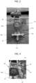
Figures 2 and 3 show an embodiment of a pneumatically-controlled actuator associated to a 3-way valve useable in the installation ofFigure 1 , -
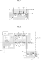
Figure 4 represents the gas regulation elements of the pressurized-gas line of the installation ofFigure 1 , -
Figure 5 shows a particular embodiment of the main gas line of the installation ofFig. 1 , and -
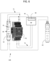
Figure 6 shows the cooperation between the timer device and the pneumatic electrovalve of the installation ofFigures 1-3 . -
Figure 1 shows aninstallation 100 for providing a gaseous compound, here gaseous oxygen or GOX, to thegas network 111 of ahospital 110, or similar facility, that delivers GOX to the different sites of use into the hospital, such as operation rooms, patient room or others. - The
Installation 100 comprises acryogenic storage vessel 1 for storing a cryogenic liquid compound, such as liquid oxygen or LOX in the present embodiment, at cryogenic temperature. Thestorage vessel 1 can contain a large volume of cryogenic liquid compound, e.g. LOX, preferably at least 3000 liters. Thecryogenic storage vessel 1 is preferably insulated for keeping LOX at cryogenic temperature, i.e. at about -196°C in the case of LOX. - The passage of LOX from the
cryogenic storage vessel 1 to afeeding line 2 is controled by adelivery valve 20, or similar means, arranged on thefeeding line 2, preferably arranged immediately at the exit 1a of thecryogenic storage vessel 1. - Optionally, the
installation 100 can comprise severalcryogenic storage vessels 1,1' arranged in parallel and fluidly connected to thefeeding line 2, that are used for providing LOX. For instance, as shown in [Fig. 1 ], theinstallation 100 can comprise amain storage vessel 1 and a secondary storage vessel 1' that is used in case of emergency, for instance when themain storage vessel 1 is empty, malfunctioning, in maintenance or the like. The secondary storage vessel 1' is fluidly connected to the thefeeding line 2 by an additional conduit 2' comprising an additional delivery valve 20' for controlling the delivery of LOX from the secondary storage vessel 1'. - The cryogenic storage vessel(s) 1 is further fluidly connected, via the
feeding line 2, such as a gas pipe, conduit or the like, to a first 3 and a second 4 derivation line that are arranged in parallel and fluidly connected to thefeeding line 2 so that LOX can be conveying in its liquid state from thecryogenic storage vessel 1 to saidderivation lines feeding line 2 is sub-divided in said (at least) twoderivation lines - Each of said
derivation lines atmospheric vaporizer atmospheric vaporizer 10 is arranged on thefirst derivation line 3 and a secondatmospheric vaporizer 11 is arranged on thesecond derivation line 4. - In said
atmospheric vaporizer - Each of said
derivation lines valve 18 arranged upstream of eachatmospheric vaporizer - Further, each of said
derivation lines atmospheric vaporizer derivation line - Furthermore, a
main gas line 5 is fluidly connected to the first andsecond derivation line atmospheric vaporizers atmospheric vaporizers main gas line 5 subsequently conveys the GOX to thegas network 111 of ahospital 110 or the like, namely to gas lines or conduits arranged in saidhospital 110 for delivering the gas in the different sites in need thereof. In other words, themain gas line 5 is fluidly connected to thegas network 111 of the hospital, i.e. conduits, pipes or similar. - Optionally, at least a part of the GOX produced in the
atmospheric vaporizers main gas line 5 can be stored, in gaseous form, in one or more buffer tank(s) 6 or the like, that is fluidly connected, by a buffer line 6', to saidmain gas line 5, downstream of theatmospheric vaporizers main gas line 5 are used for controlling the flow of GOX entering or exiting thebuffer tank 6. - Depending on the embodiment, the
main gas line 5 can be a unique conduit or the like or can be divided, i.e. ramified, in several sub-lines arranged in parallel. - First valve means 115 is arranged on the
main gas line 5 and/or on the first andsecond derivation lines atmospheric vaporizers atmospheric vaporizers second derivation lines main gas line 5. - During the conversion of LOX into GOX in one or the other of the
atmospheric vaporizers atmospheric vaporizer 10 as shown in [Fig. 1 ], anice layer 200 progressively appears around saidatmospheric vaporizer - As already mentioned, this progressive icing of the vaporizer 10 (or 11) is caused by a deposit/solidification of water vapour present in the ambient air surrounding the atmospheric vaporizer that contains LOX at cryogenic temperature (i.e. at about -196°C).
- This is a serious problem as said
ice layer 200 may deteriorate the structure of thevaporizers - According to the present invention, for trying to solve said icing issues, the first valve means 115 are configured for alternatingly allowing a flow of gaseous compound, e.g. here GOX, to be delivered by only one or the other of said first and second
atmospheric vaporizers - The duration dt is chosen so as to be sufficient for melting some to all the layer of
ice 200 formed around theatmospheric vaporizer - GOX thus produced is at a pressure of between 5 and 15 bar abs, typically of about 8 to 12 bar abs.
- Preferably, the first valve means 115 comprises a 3-
way valve 15 arranged at the point ofjunction 21 of the first andsecond derivation lines main line 5, namely downstream of theatmospheric vaporizers - Said 3-
way valve 15 comprises afirst inlet 15a fluidly connected to thefirst derivation line 3, asecond inlet 15b fluidly connected to thesecond derivation line 4 and anoutlet 15c fluidly connected to themain line 5, a shown in Fg. 1 & 2. - The first valve means 115 are configured for alternatingly providing GOX coming from one or the other of said
atmospheric vaprizers main line 5 for a prefixed duration dt, while no GOX is produced by theother vaporizer - In this way, the
ice layer 200 accumulated around theatmospheric vaporizer gas network 111 of thehospital 110 as only theatmospheric vaporizer ice layer 200 works and produces GOX. - In contrast, the other
atmospheric vaporizer ice layer 200 formed while it was running for producing GOX from LOX, does not work anymore during the prefixed duration dt so that said layer ofice 200 can naturally and slowly melt down by heat exchange with the surrounding atmosphere, and hence progressively disappears. - In other words, one of the
atmospheric vaporizers atmospheric vaporizer ice layer 200 surrounding said otheratmospheric vaporizer - The prefixed duration dt is chosen for allowing the
ice layer 200 to at least partially or completely melt down thereby freeing theatmospheric vaporizer - The alternating running of the
atmospheric vaporizers way valve 15 that is controlled for allowing LOX to circulate only in one of the two first andsecond derivation lines - The 3-
way valve 15 is controlled by actuator means 40 cooperating with said pneumatic 3-way valve 15. - The
installation 100 of the present invention further comprises pilot means 130 comprising duration setting means 31 and timer means 32 that can be embedded into atimer device 30, as shown inFigure 6 . - Duration setting means 31 can comprise one or several rotatable button(s) or selector(s), selection touch(es), cursor(s) or the like, that are configured for allowing the user choosing or selecting a desired duration dt, typically a duration dt of between 6 h and 30 h, preferably of between 8h to 24h.
- The duration setting means 31 and the timer means 32, such as a temporisation, a timer or the like, cooperate together for piloting a
pneumatic electrovalve 33, such as a solenoid valve or the like, based on the duration dt that has been set by the operator. - In short, the timer means 32 act on the coil of the
pneumatic electrovalve 33 for 'activating' or 'deactivating' said coil thereby allowing automatically-switching from one atmospheric vaporizer to the other 10, 11, and vice versa, based on the duration dt. - The
pneumatic electrovalve 33 is arranged, as shown inFig. 6 , between a pressurized-gas line 37 fluidly connected to themain line 5, and twopneumatic command lines way valve 15, as illustrated inFig. 1 ,4 & 5 . - The
pneumatic electrovalve 33 controls the delivery of gas pressure, i.e. underpressure gas, provided by the pressurized-gas line 37 to one or the other of the twopneumatic command lines way valve 15, i.e. to the actuator means 40. - Said cooperation between timer means 32 and the
pneumatic electrovalve 33 that pneumatically-controls the 3-way valve 15 useable in theinstallation 100 of the invention is illustrated inFigures 1 &4-6 . - The two pneumatic command lines 34 provide gas under pressure, such as GOX in the present embodiment,that can act on the actuator means 40 of the 3-
way valve 21 for controllling them, especially a pneumatic actuator 40-1. - The gas under pressure can be GOX provided by a pressurized-
gas line 37 fluidly connected to themain line 5, namely downstream of the 3-way valve 15, as represented inFig. 1 . - The pressurized-
gas line 37 preferably comprisesgas regulation elements 38 as detailed inFig. 4 , comprising an on/off valve 38-1, a pressure reducer 38-2 for controlling the pressure level, and an over-pressure safety valve 38-3 in fluid communication with the atmosphere for venting any over-pressure to the atmosphere. - Actuator means 40 preferably comprise a pneumatic actuator 40-1 as shown in
Fig. 2 and 3 , associated to the valve means 115, especially the 3-way valve 15 for pneumatically controlling said 3-way valve 15 in order to open or close the first and/orsecond inlets atmospheric vaporizers main line 5, via theoutlet 15c. - Thus, one of the two
pneumatic command lines first way 15a of the 3-way valve 15 for the duration dt, whereas the other of the twopneumatic command lines second way 15a of the 3-way valve 15, and vice versa. - In other words, pilot means 130 are configured for pneumatically-controlling the 3-
way valve 15 via thepneumatic electrovalve 33, the twopneumatic command lines timer device 30, as shown inFigure 6 . - As shown in
Fig. 2 & , the twopneumatic command lines pressure inlets 41 of the pneumatic actuator 40-1, i.e. the actuator means 40, preferably by threadedconnectors 42 or the like. - As shown in
Fig. 6 , electric power means 70, such as an AC/DC power supply, are provided for delivering electric current to all the elements or parts of theinstallation 100 that require electric power to work, in particular to thetimer device 30, to the coil of thepneumatic electrovalve 33, to amonitoring device 80 or any other elements in need thereof. - The electric power means 70, especially the AC/DC power supply, can be electrically-connected to the mains (110/220V) as the power source and, if need be, to a power converter for converting a high voltage, e.g. 110/220V, into a lower voltage, e.g. 24V or any other suitable voltage.
- As illustrated in
Fig. 6 , the electric power means 70 provide power, via electric lines,cables 71 or the like, to the coil of the pneumatic electrovalve 33 and to thetimer device 30, and further to themonitoring device 80. - In the present embodiment, the
installation 100 further comprises amonitoring device 80 comprising ahousing 81 and adisplay screen 82 for displaying various information, such as alarms, temperatures or any other information. - The
monitoring device 80 can comprise a (micro)processor or the like, for instance an electronic card, for processing data, signals or measurements provided by temperature sensors 55 as saidmonitoring device 80 is connected to temperature sensors 55 arranged upstream of the gas line portions 5-1, 5-2. Thanks to themonitoring device 80, it is possible to control the temperature of GOX provided by the twoatmospheric vaporizers -
Figure 5 shows a particular embodiment of themain gas line 5 of theinstallation 100 ofFig. 1 , wherein saidmain gas line 5 is divided into two gas line portions 5-1, 5-2, arranged in parallel. - Each gas line portion 5-1, 5-2 comprises, arranged in serial, a first
manual valve 50, apressure reducer 51, a secondmanual pressure sensor 52 for measuring the reduced pressure, and asecond valve 53. Further, afirst pressure sensor 54 can be arranged upstream of thefirst valve 50 on one of the gas line portions 5-1, 5-2 for measuring the inlet pressure, namely the pressure provided by the 3-way valve 15. - Such gas line portions 5-1, 5-2 can be helpful for controlling the gas pressure of GOX provided by the two
atmospheric vaporizers network 11 of thehospital 110 or the like. - Further, as already mentioned, the
main gas line 5 can also comprise temperature sensors 55 arranged upstream of the gas line portions 5-1, 5-2, so that it is possible to control the temperature of GOX provided by the twoatmospheric vaporizers atmospheric vaporizer - Optionally, the
main gas line 5 can also be provided with oxygen coming from the secondary storage vessel 1' that is used in case of emergency, via anemergency gas line 60 equiped with avalve 61 as shown inFig. 5 . If the secondary storage vessel 1' contains LOX, it will have to be vaporized before being conveyed byemergency gas line 60, for instance by means of an additional atmospheric vaporizer (not shown) arranged between the secondary storage vessel 1' and theemergency gas line 60. - Generally speaking, the
installation 100 and the process of the present invention can work automatically, once the duration dt is set by the operator, for instance a duration of about 6h to 24h. The switching between the first and thesecond derivation lines ice layer 200 of the not-usedatmospheric vaporizer atmospheric vaporizer - In other words, the
installation 100 and process of the present invention allow an automatic switch from one atmospheric vaporizer (that is stopped, i.e. does not work anymore) to otheratmospheric vaporizer
Claims (15)
- Installation (100) for providing a gaseous compound to a building (110), such as a hospital, comprising :- at least one cryogenic storage vessel (1) for storing a liquid compound at cryogenic temperature,- at least one feeding line (2) for conveying a flow of liquid compound from said at least one cryogenic storage vessel (1) to at least a first (3) and a second (4) derivation lines arranged in parallel and fluidly connected to said at least one feeding line (2),- at least a first atmospheric vaporizer (10) arranged on the first derivation line (3) and at least a second atmospheric vaporizer (11) arranged on the second derivation line (4), said first and second atmospheric vaporizers (10, 11) being configured for vaporizing said liquid compound thereby obtaining a gaseous compound,- at least one main gas line (5) fluidly connected to the first and second derivation line (3, 4), downstream of the first and second atmospheric vaporizers (10, 11), for recovering and conveying the gaseous compound vaporized in said atmospheric vaporizers (10, 11),- first valve means (115) arranged on the main line (5) and/or on the first and second derivation lines (3, 4), downstream of the first and second atmospheric vaporizers (10, 11), for controling the flow of gaseous compound provided by said first and second atmospheric vaporizers (10, 11),and wherein said first valve means (115) are piloted by pilot means (130) for alternatively providing to the main line (5), a flow of gaseous compound coming from one or the other of said first and second atmospheric vaporizers (10, 11), based on a prefixed duration (dt).
- Installation according to claim 1, characterized in that said first valve means (115) are piloted for allowing, for the prefixed duration (dt), a flow of gaseous compound coming from the first atmospheric vaporizer (10) to pass into the main line (5), and simultaneously interrupting the flow of gaseous compound coming from the second atmospheric vaporizer (11), and vice versa.
- Installation according to any one of claims 1 or 2, characterized in that the prefixed duration is of between 8 hours and 24 hours.
- Installation according to any one of claims 1 to 3, characterized in that said first valve means (115) comprise a 3-way valve (15) comprising :- a first inlet (15a) fluidly connected to the first derivation line (3),- a second inlet (15b) fluidly connected to second derivation line (4) and- an outlet (15c) fluidly connected to the main line (5).
- Installation according to claim 1, characterized in that said pilot means (130) comprise timer means (32) and duration setting means (31) for setting the desired duration (dt), preferably a rotative selector.
- Installation according to claim 5, characterized in that the first valve means (115) cooperate with actuator means (40) controlled by the pilot means (130) for alternatively providing to the main line (5), a flow of gaseous compound coming from one or the other of said first and second atmospheric vaporizers (10, 11).
- Installation according to claims 4 and 6, characterized in that the actuator means (40) are pneumatically-controlled by the pilot means (130).
- Installation according to claims 4 and 6 or 7, characterized in that said actuator means (40) are pneumatically controlled by the pilot means (130) for acting on the first valve means (115) for automatically switching the delivery of the flow of gaseous compound from the first inlet (15a) to the second inlet (15b) of the 3-way valve (15), or vice versa, to the main line (5), based on the prefixed duration (dt).
- Installation according to any one of the preceding claims, characterized in that said actuator means (40) comprise a pneumatic actuator (40-1) pneumatically controlled by the pilot means (130) via two pneumatic-control lines (35a, 35b) and a pneumatic electovalve (33).
- Installation according to claim 9, characterized in that the two pneumatic-control lines (35a, 35b) are in fluid communication, through the pneumatic electovalve (33), with a pressurized-gas line (37) fluidly connected to the main line (5), downstream of the 3-way valve (15).
- Installation according to any one of the preceding claims, characterized in that the pilot means (130) further comprise a timer device (30) comprising the timer means (32) and duration setting means (31).
- Installation according to any one of the preceding claims, characterized in that :- the liquid compound is liquid oxygen (LOX) and the gaseous compound is gaseous oxygen (GOX) or- the liquid compound is liquid nitrogen (LN2) and the gaseous compound is gaseous nitrogen (GN2).
- Process for providing a gaseous compound to a building (110), such as a hospital, comprising the steps of :a) storing a liquid compound at cryogenic temperature into at least one cryogenic storage vessel (1),b) conveying by means of at least one feeding line (2), a flow of liquid compound from said at least one cryogenic storage vessel (1) to at least a first (3) and a second (4) derivation lines arranged in parallel and fluidly connected to said at least one feeding line (2),c) vaporizing said liquid compound by means of at least a first atmospheric vaporizer (10) arranged on the first derivation line (3) and at least a second atmospheric vaporizer (11) arranged on the second derivation line (4), thereby obtaining a gaseous compound,d) recovering and conveying the gaseous compound vaporized in said atmospheric vaporizers (10, 11) by means of at least one main gas line (5) fluidly connected to the first and second derivation line (3, 4), downstream of the first and second atmospheric vaporizers (10, 11),e) controling the flow of gaseous compound provided by the first and second atmospheric vaporizers (10, 11), by means of first valve means (115) arranged on the main line (5) and/or on the first and second derivation lines (3, 4), downstream of the first and second atmospheric vaporizers (10, 11), said first valve means (115) being controlled by pilot means (130) andf) alternatively providing to the main line (5), through the first valve means (115), a flow of gaseous compound coming from one or the other of said first and second atmospheric vaporizers (10, 11), based on a prefixed duration (dt).
- Process according to Claim 13, characterized in that the first valve means (115) comprise a 3-way valve (15).
- Process according to Claim 13, characterized in that:- the liquid compound is liquid oxygen (LOX) and the gaseous compound is gaseous oxygen (GOX), or the liquid compound is liquid nitrogen (LN2) and the gaseous compound is gaseous nitrogen (GN2), and- the prefixed duration is of between 6 and 30 hours, preferably of between 8 and 24 hours.
Priority Applications (1)
| Application Number | Priority Date | Filing Date | Title |
|---|---|---|---|
| EP22170760.7A EP4269861B1 (en) | 2022-04-29 | 2022-04-29 | Installation and process for providing a medical gas to a hospital |
Applications Claiming Priority (1)
| Application Number | Priority Date | Filing Date | Title |
|---|---|---|---|
| EP22170760.7A EP4269861B1 (en) | 2022-04-29 | 2022-04-29 | Installation and process for providing a medical gas to a hospital |
Publications (2)
| Publication Number | Publication Date |
|---|---|
| EP4269861A1 true EP4269861A1 (en) | 2023-11-01 |
| EP4269861B1 EP4269861B1 (en) | 2026-01-28 |
Family
ID=81448694
Family Applications (1)
| Application Number | Title | Priority Date | Filing Date |
|---|---|---|---|
| EP22170760.7A Active EP4269861B1 (en) | 2022-04-29 | 2022-04-29 | Installation and process for providing a medical gas to a hospital |
Country Status (1)
| Country | Link |
|---|---|
| EP (1) | EP4269861B1 (en) |
Cited By (1)
| Publication number | Priority date | Publication date | Assignee | Title |
|---|---|---|---|---|
| EP4667813A1 (en) | 2024-06-20 | 2025-12-24 | L'air Liquide, Societe Anonyme Pour L'etude Et L'exploitation Des Procedes Georges Claude | Gas distribution plant for supplying gaseous oxygen to a hospital facility |
Citations (5)
| Publication number | Priority date | Publication date | Assignee | Title |
|---|---|---|---|---|
| US2833121A (en) * | 1953-11-24 | 1958-05-06 | Union Carbide Corp | Apparatus for vaporizing volatile liquids |
| DE4025138A1 (en) * | 1990-08-08 | 1992-02-13 | Messer Griesheim Gmbh | Defrosting liquefied gas vaporiser - involves directing some gas from after-heater through group being defrosted |
| DE102007008534A1 (en) * | 2007-02-21 | 2008-08-28 | Linde Ag | Apparatus for vaporizing cryogenic media and method for defrosting an evaporator unit of such apparatus |
| JP2011137608A (en) * | 2009-12-28 | 2011-07-14 | Creative Techno Solution Co Ltd | Liquefied fuel gas vaporizer |
| US8069678B1 (en) * | 2006-06-07 | 2011-12-06 | Bernert Robert E | Heat transfer in the liquefied gas regasification process |
-
2022
- 2022-04-29 EP EP22170760.7A patent/EP4269861B1/en active Active
Patent Citations (5)
| Publication number | Priority date | Publication date | Assignee | Title |
|---|---|---|---|---|
| US2833121A (en) * | 1953-11-24 | 1958-05-06 | Union Carbide Corp | Apparatus for vaporizing volatile liquids |
| DE4025138A1 (en) * | 1990-08-08 | 1992-02-13 | Messer Griesheim Gmbh | Defrosting liquefied gas vaporiser - involves directing some gas from after-heater through group being defrosted |
| US8069678B1 (en) * | 2006-06-07 | 2011-12-06 | Bernert Robert E | Heat transfer in the liquefied gas regasification process |
| DE102007008534A1 (en) * | 2007-02-21 | 2008-08-28 | Linde Ag | Apparatus for vaporizing cryogenic media and method for defrosting an evaporator unit of such apparatus |
| JP2011137608A (en) * | 2009-12-28 | 2011-07-14 | Creative Techno Solution Co Ltd | Liquefied fuel gas vaporizer |
Cited By (2)
| Publication number | Priority date | Publication date | Assignee | Title |
|---|---|---|---|---|
| EP4667813A1 (en) | 2024-06-20 | 2025-12-24 | L'air Liquide, Societe Anonyme Pour L'etude Et L'exploitation Des Procedes Georges Claude | Gas distribution plant for supplying gaseous oxygen to a hospital facility |
| FR3163709A1 (en) * | 2024-06-20 | 2025-12-26 | L'air Liquide, Societe Anonyme Pour L'etude Et L'exploitation Des Procedes Georges Claude | Gas distribution system to supply oxygen gas to a hospital facility |
Also Published As
| Publication number | Publication date |
|---|---|
| EP4269861B1 (en) | 2026-01-28 |
Similar Documents
| Publication | Publication Date | Title |
|---|---|---|
| US7594545B2 (en) | System and methods for preventing ignition and fire via a maintained hypoxic environment | |
| US7753049B2 (en) | Remote control fluid regulation system | |
| US8251057B2 (en) | Hyperbaric chamber control and/or monitoring system and methods for using the same | |
| US11596759B2 (en) | Methods and systems for a medical gas delivery module | |
| US7263995B2 (en) | Hyperbaric oxygen therapy system controls | |
| AU2005299616B2 (en) | Liquefying and storing a gas | |
| EP4269861B1 (en) | Installation and process for providing a medical gas to a hospital | |
| US20160003524A1 (en) | System and method for storage and delivery of cryogenic liquid air | |
| US3199303A (en) | Oxygen therapy system | |
| US6167318A (en) | Oil mist generating system and method | |
| US20110248856A1 (en) | Gas flow and pressure error alarm | |
| JP2010506641A (en) | Deactivation device with nitrogen generator | |
| EP0324310A1 (en) | Installation for the supply of oxygen in hospitals and the like | |
| JP2016532289A (en) | Remote delivery of chemical reagents | |
| CA2794646C (en) | Apparatus for purging hydrogen cooling gas from a turbine and high flow co2 delivery system | |
| EP2569570B1 (en) | Method for producing sterile cryogenic liquid | |
| EP4161622B1 (en) | Ventilator | |
| EP1139007B1 (en) | Apparatus and method for regulating gas flow | |
| KR20010015002A (en) | Pressure-regulating device for a cryogenic tank and plant for delivering corresponding fluid | |
| US2464835A (en) | Control system for gas supply apparatus | |
| JPS62290470A (en) | Apparatus for filling oxygen container used in medical oxygen remedyy with enriched respiration air | |
| JP6968525B2 (en) | Liquid nitrogen supply system | |
| EP3839393A1 (en) | A method and apparatus for supplying a cryogenic stream with a controlled temperature from a back-up system | |
| US20070204631A1 (en) | Liquefied Chemical Gas Delivery System | |
| JPH0654910A (en) | Oxygen-enriched gas feeding system and device therefor |
Legal Events
| Date | Code | Title | Description |
|---|---|---|---|
| PUAI | Public reference made under article 153(3) epc to a published international application that has entered the european phase |
Free format text: ORIGINAL CODE: 0009012 |
|
| STAA | Information on the status of an ep patent application or granted ep patent |
Free format text: STATUS: THE APPLICATION HAS BEEN PUBLISHED |
|
| AK | Designated contracting states |
Kind code of ref document: A1 Designated state(s): AL AT BE BG CH CY CZ DE DK EE ES FI FR GB GR HR HU IE IS IT LI LT LU LV MC MK MT NL NO PL PT RO RS SE SI SK SM TR |
|
| STAA | Information on the status of an ep patent application or granted ep patent |
Free format text: STATUS: REQUEST FOR EXAMINATION WAS MADE |
|
| 17P | Request for examination filed |
Effective date: 20240502 |
|
| RBV | Designated contracting states (corrected) |
Designated state(s): AL AT BE BG CH CY CZ DE DK EE ES FI FR GB GR HR HU IE IS IT LI LT LU LV MC MK MT NL NO PL PT RO RS SE SI SK SM TR |
|
| GRAP | Despatch of communication of intention to grant a patent |
Free format text: ORIGINAL CODE: EPIDOSNIGR1 |
|
| STAA | Information on the status of an ep patent application or granted ep patent |
Free format text: STATUS: GRANT OF PATENT IS INTENDED |
|
| GRAJ | Information related to disapproval of communication of intention to grant by the applicant or resumption of examination proceedings by the epo deleted |
Free format text: ORIGINAL CODE: EPIDOSDIGR1 |
|
| STAA | Information on the status of an ep patent application or granted ep patent |
Free format text: STATUS: REQUEST FOR EXAMINATION WAS MADE |
|
| RIC1 | Information provided on ipc code assigned before grant |
Ipc: F17C 9/02 20060101AFI20250620BHEP |
|
| INTG | Intention to grant announced |
Effective date: 20250702 |
|
| INTC | Intention to grant announced (deleted) | ||
| GRAP | Despatch of communication of intention to grant a patent |
Free format text: ORIGINAL CODE: EPIDOSNIGR1 |
|
| STAA | Information on the status of an ep patent application or granted ep patent |
Free format text: STATUS: GRANT OF PATENT IS INTENDED |
|
| RAP1 | Party data changed (applicant data changed or rights of an application transferred) |
Owner name: AIR LIQUIDE ITALIA GAS E SERVIZI S.R.L. Owner name: L'AIR LIQUIDE, SOCIETE ANONYME POUR L'ETUDE ETL'EXPLOITATION DES PROCEDES GEORGES CLAUDE |
|
| INTG | Intention to grant announced |
Effective date: 20250902 |
|
| GRAS | Grant fee paid |
Free format text: ORIGINAL CODE: EPIDOSNIGR3 |
|
| GRAA | (expected) grant |
Free format text: ORIGINAL CODE: 0009210 |
|
| STAA | Information on the status of an ep patent application or granted ep patent |
Free format text: STATUS: THE PATENT HAS BEEN GRANTED |
|
| AK | Designated contracting states |
Kind code of ref document: B1 Designated state(s): AL AT BE BG CH CY CZ DE DK EE ES FI FR GB GR HR HU IE IS IT LI LT LU LV MC MK MT NL NO PL PT RO RS SE SI SK SM TR |
|
| REG | Reference to a national code |
Ref country code: CH Ref legal event code: F10 Free format text: ST27 STATUS EVENT CODE: U-0-0-F10-F00 (AS PROVIDED BY THE NATIONAL OFFICE) Effective date: 20260128 Ref country code: GB Ref legal event code: FG4D |
|
| REG | Reference to a national code |
Ref country code: DE Ref legal event code: R096 Ref document number: 602022029078 Country of ref document: DE |
|
| REG | Reference to a national code |
Ref country code: IE Ref legal event code: FG4D |
|
| REG | Reference to a national code |
Ref country code: NL Ref legal event code: MP Effective date: 20260128 |
|
| PG25 | Lapsed in a contracting state [announced via postgrant information from national office to epo] |
Ref country code: NL Free format text: LAPSE BECAUSE OF FAILURE TO SUBMIT A TRANSLATION OF THE DESCRIPTION OR TO PAY THE FEE WITHIN THE PRESCRIBED TIME-LIMIT Effective date: 20260128 |
|
| REG | Reference to a national code |
Ref country code: AT Ref legal event code: MK05 Ref document number: 1881651 Country of ref document: AT Kind code of ref document: T Effective date: 20260128 |
|
| PG25 | Lapsed in a contracting state [announced via postgrant information from national office to epo] |
Ref country code: RS Free format text: LAPSE BECAUSE OF FAILURE TO SUBMIT A TRANSLATION OF THE DESCRIPTION OR TO PAY THE FEE WITHIN THE PRESCRIBED TIME-LIMIT Effective date: 20260428 |
|
| PG25 | Lapsed in a contracting state [announced via postgrant information from national office to epo] |
Ref country code: ES Free format text: LAPSE BECAUSE OF FAILURE TO SUBMIT A TRANSLATION OF THE DESCRIPTION OR TO PAY THE FEE WITHIN THE PRESCRIBED TIME-LIMIT Effective date: 20260128 |
|
| PG25 | Lapsed in a contracting state [announced via postgrant information from national office to epo] |
Ref country code: PL Free format text: LAPSE BECAUSE OF FAILURE TO SUBMIT A TRANSLATION OF THE DESCRIPTION OR TO PAY THE FEE WITHIN THE PRESCRIBED TIME-LIMIT Effective date: 20260128 |
|
| PG25 | Lapsed in a contracting state [announced via postgrant information from national office to epo] |
Ref country code: GR Free format text: LAPSE BECAUSE OF FAILURE TO SUBMIT A TRANSLATION OF THE DESCRIPTION OR TO PAY THE FEE WITHIN THE PRESCRIBED TIME-LIMIT Effective date: 20260429 |
|
| PGFP | Annual fee paid to national office [announced via postgrant information from national office to epo] |
Ref country code: IT Payment date: 20260429 Year of fee payment: 5 |
|
| REG | Reference to a national code |
Ref country code: LT Ref legal event code: MG9D |
|
| PG25 | Lapsed in a contracting state [announced via postgrant information from national office to epo] |
Ref country code: LT Free format text: LAPSE BECAUSE OF FAILURE TO SUBMIT A TRANSLATION OF THE DESCRIPTION OR TO PAY THE FEE WITHIN THE PRESCRIBED TIME-LIMIT Effective date: 20260128 |
|
| PG25 | Lapsed in a contracting state [announced via postgrant information from national office to epo] |
Ref country code: NO Free format text: LAPSE BECAUSE OF FAILURE TO SUBMIT A TRANSLATION OF THE DESCRIPTION OR TO PAY THE FEE WITHIN THE PRESCRIBED TIME-LIMIT Effective date: 20260428 |
|
| PG25 | Lapsed in a contracting state [announced via postgrant information from national office to epo] |
Ref country code: SE Free format text: LAPSE BECAUSE OF FAILURE TO SUBMIT A TRANSLATION OF THE DESCRIPTION OR TO PAY THE FEE WITHIN THE PRESCRIBED TIME-LIMIT Effective date: 20260128 Ref country code: AT Free format text: LAPSE BECAUSE OF FAILURE TO SUBMIT A TRANSLATION OF THE DESCRIPTION OR TO PAY THE FEE WITHIN THE PRESCRIBED TIME-LIMIT Effective date: 20260128 Ref country code: FI Free format text: LAPSE BECAUSE OF FAILURE TO SUBMIT A TRANSLATION OF THE DESCRIPTION OR TO PAY THE FEE WITHIN THE PRESCRIBED TIME-LIMIT Effective date: 20260128 |
|
| PG25 | Lapsed in a contracting state [announced via postgrant information from national office to epo] |
Ref country code: HR Free format text: LAPSE BECAUSE OF FAILURE TO SUBMIT A TRANSLATION OF THE DESCRIPTION OR TO PAY THE FEE WITHIN THE PRESCRIBED TIME-LIMIT Effective date: 20260128 |
|
| PG25 | Lapsed in a contracting state [announced via postgrant information from national office to epo] |
Ref country code: PT Free format text: LAPSE BECAUSE OF FAILURE TO SUBMIT A TRANSLATION OF THE DESCRIPTION OR TO PAY THE FEE WITHIN THE PRESCRIBED TIME-LIMIT Effective date: 20260528 Ref country code: IS Free format text: LAPSE BECAUSE OF FAILURE TO SUBMIT A TRANSLATION OF THE DESCRIPTION OR TO PAY THE FEE WITHIN THE PRESCRIBED TIME-LIMIT Effective date: 20260528 |
|
| PGFP | Annual fee paid to national office [announced via postgrant information from national office to epo] |
Ref country code: FR Payment date: 20260420 Year of fee payment: 5 |
|
| PG25 | Lapsed in a contracting state [announced via postgrant information from national office to epo] |
Ref country code: LV Free format text: LAPSE BECAUSE OF FAILURE TO SUBMIT A TRANSLATION OF THE DESCRIPTION OR TO PAY THE FEE WITHIN THE PRESCRIBED TIME-LIMIT Effective date: 20260128 |
|
| PG25 | Lapsed in a contracting state [announced via postgrant information from national office to epo] |
Ref country code: BG Free format text: LAPSE BECAUSE OF FAILURE TO SUBMIT A TRANSLATION OF THE DESCRIPTION OR TO PAY THE FEE WITHIN THE PRESCRIBED TIME-LIMIT Effective date: 20260128 |