EP4269858A1 - Apparatus for fuel cell system - Google Patents
Apparatus for fuel cell system Download PDFInfo
- Publication number
- EP4269858A1 EP4269858A1 EP22186333.5A EP22186333A EP4269858A1 EP 4269858 A1 EP4269858 A1 EP 4269858A1 EP 22186333 A EP22186333 A EP 22186333A EP 4269858 A1 EP4269858 A1 EP 4269858A1
- Authority
- EP
- European Patent Office
- Prior art keywords
- fuel cell
- cell system
- hydrogen tank
- controller
- slave
- Prior art date
- Legal status (The legal status is an assumption and is not a legal conclusion. Google has not performed a legal analysis and makes no representation as to the accuracy of the status listed.)
- Pending
Links
Images




Classifications
-
- H—ELECTRICITY
- H01—ELECTRIC ELEMENTS
- H01M—PROCESSES OR MEANS, e.g. BATTERIES, FOR THE DIRECT CONVERSION OF CHEMICAL ENERGY INTO ELECTRICAL ENERGY
- H01M8/00—Fuel cells; Manufacture thereof
- H01M8/04—Auxiliary arrangements, e.g. for control of pressure or for circulation of fluids
- H01M8/04298—Processes for controlling fuel cells or fuel cell systems
- H01M8/04694—Processes for controlling fuel cells or fuel cell systems characterised by variables to be controlled
- H01M8/04746—Pressure; Flow
- H01M8/04753—Pressure; Flow of fuel cell reactants
-
- H—ELECTRICITY
- H01—ELECTRIC ELEMENTS
- H01M—PROCESSES OR MEANS, e.g. BATTERIES, FOR THE DIRECT CONVERSION OF CHEMICAL ENERGY INTO ELECTRICAL ENERGY
- H01M8/00—Fuel cells; Manufacture thereof
- H01M8/04—Auxiliary arrangements, e.g. for control of pressure or for circulation of fluids
- H01M8/04082—Arrangements for control of reactant parameters, e.g. pressure or concentration
- H01M8/04201—Reactant storage and supply, e.g. means for feeding, pipes
-
- H—ELECTRICITY
- H01—ELECTRIC ELEMENTS
- H01M—PROCESSES OR MEANS, e.g. BATTERIES, FOR THE DIRECT CONVERSION OF CHEMICAL ENERGY INTO ELECTRICAL ENERGY
- H01M8/00—Fuel cells; Manufacture thereof
- H01M8/04—Auxiliary arrangements, e.g. for control of pressure or for circulation of fluids
- H01M8/04082—Arrangements for control of reactant parameters, e.g. pressure or concentration
- H01M8/04089—Arrangements for control of reactant parameters, e.g. pressure or concentration of gaseous reactants
-
- H—ELECTRICITY
- H01—ELECTRIC ELEMENTS
- H01M—PROCESSES OR MEANS, e.g. BATTERIES, FOR THE DIRECT CONVERSION OF CHEMICAL ENERGY INTO ELECTRICAL ENERGY
- H01M8/00—Fuel cells; Manufacture thereof
- H01M8/04—Auxiliary arrangements, e.g. for control of pressure or for circulation of fluids
- H01M8/04298—Processes for controlling fuel cells or fuel cell systems
-
- H—ELECTRICITY
- H01—ELECTRIC ELEMENTS
- H01M—PROCESSES OR MEANS, e.g. BATTERIES, FOR THE DIRECT CONVERSION OF CHEMICAL ENERGY INTO ELECTRICAL ENERGY
- H01M8/00—Fuel cells; Manufacture thereof
- H01M8/04—Auxiliary arrangements, e.g. for control of pressure or for circulation of fluids
- H01M8/04298—Processes for controlling fuel cells or fuel cell systems
- H01M8/04313—Processes for controlling fuel cells or fuel cell systems characterised by the detection or assessment of variables; characterised by the detection or assessment of failure or abnormal function
- H01M8/0432—Temperature; Ambient temperature
-
- H—ELECTRICITY
- H01—ELECTRIC ELEMENTS
- H01M—PROCESSES OR MEANS, e.g. BATTERIES, FOR THE DIRECT CONVERSION OF CHEMICAL ENERGY INTO ELECTRICAL ENERGY
- H01M8/00—Fuel cells; Manufacture thereof
- H01M8/04—Auxiliary arrangements, e.g. for control of pressure or for circulation of fluids
- H01M8/04298—Processes for controlling fuel cells or fuel cell systems
- H01M8/04313—Processes for controlling fuel cells or fuel cell systems characterised by the detection or assessment of variables; characterised by the detection or assessment of failure or abnormal function
- H01M8/0432—Temperature; Ambient temperature
- H01M8/04328—Temperature; Ambient temperature of anode reactants at the inlet or inside the fuel cell
-
- H—ELECTRICITY
- H01—ELECTRIC ELEMENTS
- H01M—PROCESSES OR MEANS, e.g. BATTERIES, FOR THE DIRECT CONVERSION OF CHEMICAL ENERGY INTO ELECTRICAL ENERGY
- H01M8/00—Fuel cells; Manufacture thereof
- H01M8/04—Auxiliary arrangements, e.g. for control of pressure or for circulation of fluids
- H01M8/04298—Processes for controlling fuel cells or fuel cell systems
- H01M8/04313—Processes for controlling fuel cells or fuel cell systems characterised by the detection or assessment of variables; characterised by the detection or assessment of failure or abnormal function
- H01M8/0432—Temperature; Ambient temperature
- H01M8/04373—Temperature; Ambient temperature of auxiliary devices, e.g. reformers, compressors, burners
-
- H—ELECTRICITY
- H01—ELECTRIC ELEMENTS
- H01M—PROCESSES OR MEANS, e.g. BATTERIES, FOR THE DIRECT CONVERSION OF CHEMICAL ENERGY INTO ELECTRICAL ENERGY
- H01M8/00—Fuel cells; Manufacture thereof
- H01M8/04—Auxiliary arrangements, e.g. for control of pressure or for circulation of fluids
- H01M8/04298—Processes for controlling fuel cells or fuel cell systems
- H01M8/04313—Processes for controlling fuel cells or fuel cell systems characterised by the detection or assessment of variables; characterised by the detection or assessment of failure or abnormal function
- H01M8/0438—Pressure; Ambient pressure; Flow
-
- H—ELECTRICITY
- H01—ELECTRIC ELEMENTS
- H01M—PROCESSES OR MEANS, e.g. BATTERIES, FOR THE DIRECT CONVERSION OF CHEMICAL ENERGY INTO ELECTRICAL ENERGY
- H01M8/00—Fuel cells; Manufacture thereof
- H01M8/04—Auxiliary arrangements, e.g. for control of pressure or for circulation of fluids
- H01M8/04298—Processes for controlling fuel cells or fuel cell systems
- H01M8/04313—Processes for controlling fuel cells or fuel cell systems characterised by the detection or assessment of variables; characterised by the detection or assessment of failure or abnormal function
- H01M8/0438—Pressure; Ambient pressure; Flow
- H01M8/04388—Pressure; Ambient pressure; Flow of anode reactants at the inlet or inside the fuel cell
-
- H—ELECTRICITY
- H01—ELECTRIC ELEMENTS
- H01M—PROCESSES OR MEANS, e.g. BATTERIES, FOR THE DIRECT CONVERSION OF CHEMICAL ENERGY INTO ELECTRICAL ENERGY
- H01M8/00—Fuel cells; Manufacture thereof
- H01M8/04—Auxiliary arrangements, e.g. for control of pressure or for circulation of fluids
- H01M8/04298—Processes for controlling fuel cells or fuel cell systems
- H01M8/04313—Processes for controlling fuel cells or fuel cell systems characterised by the detection or assessment of variables; characterised by the detection or assessment of failure or abnormal function
- H01M8/0438—Pressure; Ambient pressure; Flow
- H01M8/04425—Pressure; Ambient pressure; Flow at auxiliary devices, e.g. reformers, compressors, burners
-
- H—ELECTRICITY
- H01—ELECTRIC ELEMENTS
- H01M—PROCESSES OR MEANS, e.g. BATTERIES, FOR THE DIRECT CONVERSION OF CHEMICAL ENERGY INTO ELECTRICAL ENERGY
- H01M8/00—Fuel cells; Manufacture thereof
- H01M8/04—Auxiliary arrangements, e.g. for control of pressure or for circulation of fluids
- H01M8/04298—Processes for controlling fuel cells or fuel cell systems
- H01M8/04694—Processes for controlling fuel cells or fuel cell systems characterised by variables to be controlled
- H01M8/04701—Temperature
-
- H—ELECTRICITY
- H01—ELECTRIC ELEMENTS
- H01M—PROCESSES OR MEANS, e.g. BATTERIES, FOR THE DIRECT CONVERSION OF CHEMICAL ENERGY INTO ELECTRICAL ENERGY
- H01M8/00—Fuel cells; Manufacture thereof
- H01M8/04—Auxiliary arrangements, e.g. for control of pressure or for circulation of fluids
- H01M8/04298—Processes for controlling fuel cells or fuel cell systems
- H01M8/04694—Processes for controlling fuel cells or fuel cell systems characterised by variables to be controlled
- H01M8/04746—Pressure; Flow
-
- H—ELECTRICITY
- H01—ELECTRIC ELEMENTS
- H01M—PROCESSES OR MEANS, e.g. BATTERIES, FOR THE DIRECT CONVERSION OF CHEMICAL ENERGY INTO ELECTRICAL ENERGY
- H01M8/00—Fuel cells; Manufacture thereof
- H01M8/04—Auxiliary arrangements, e.g. for control of pressure or for circulation of fluids
- H01M8/04298—Processes for controlling fuel cells or fuel cell systems
- H01M8/04992—Processes for controlling fuel cells or fuel cell systems characterised by the implementation of mathematical or computational algorithms, e.g. feedback control loops, fuzzy logic, neural networks or artificial intelligence
-
- H—ELECTRICITY
- H01—ELECTRIC ELEMENTS
- H01M—PROCESSES OR MEANS, e.g. BATTERIES, FOR THE DIRECT CONVERSION OF CHEMICAL ENERGY INTO ELECTRICAL ENERGY
- H01M2250/00—Fuel cells for particular applications; Specific features of fuel cell system
- H01M2250/10—Fuel cells in stationary systems, e.g. emergency power source in plant
-
- H—ELECTRICITY
- H01—ELECTRIC ELEMENTS
- H01M—PROCESSES OR MEANS, e.g. BATTERIES, FOR THE DIRECT CONVERSION OF CHEMICAL ENERGY INTO ELECTRICAL ENERGY
- H01M8/00—Fuel cells; Manufacture thereof
- H01M8/04—Auxiliary arrangements, e.g. for control of pressure or for circulation of fluids
- H01M8/04298—Processes for controlling fuel cells or fuel cell systems
- H01M8/04694—Processes for controlling fuel cells or fuel cell systems characterised by variables to be controlled
- H01M8/04746—Pressure; Flow
- H01M8/04776—Pressure; Flow at auxiliary devices, e.g. reformer, compressor, burner
-
- Y—GENERAL TAGGING OF NEW TECHNOLOGICAL DEVELOPMENTS; GENERAL TAGGING OF CROSS-SECTIONAL TECHNOLOGIES SPANNING OVER SEVERAL SECTIONS OF THE IPC; TECHNICAL SUBJECTS COVERED BY FORMER USPC CROSS-REFERENCE ART COLLECTIONS [XRACs] AND DIGESTS
- Y02—TECHNOLOGIES OR APPLICATIONS FOR MITIGATION OR ADAPTATION AGAINST CLIMATE CHANGE
- Y02E—REDUCTION OF GREENHOUSE GAS [GHG] EMISSIONS, RELATED TO ENERGY GENERATION, TRANSMISSION OR DISTRIBUTION
- Y02E60/00—Enabling technologies; Technologies with a potential or indirect contribution to GHG emissions mitigation
- Y02E60/30—Hydrogen technology
- Y02E60/50—Fuel cells
Definitions
- An embodiment of the present disclosure relates to an apparatus for a fuel cell system and a control device and method for the fuel cell system, and more particularly, to a distributed control module for a fuel cell system.
- An apparatus for a fuel cell system includes a master controller and at least one slave controller connected to the master controller.
- the at least one slave controller may be connected to a valve connected to a hydrogen tank.
- the at least one slave controller may include a first slave controller and a second slave controller, the first slave controller may be connected to a first hydrogen tank valve, and the second slave controller may be connected to a second hydrogen tank valve.
- the apparatus for a fuel cell system may further include a first hydrogen tank connected to the first hydrogen tank valve, and a second hydrogen tank connected to the second hydrogen tank valve.
- the master controller may include a master connector for connection to the at least one slave controller.
- the at least one slave controller may include a slave connector for connection to the master controller.
- the at least one slave controller may further include a hydrogen tank valve connector for connection to a hydrogen tank valve.
- control device for a fuel cell system may further include a fuel cell controller configured to deliver a control command regarding the hydrogen tank valve to the master controller.
- a control device for a fuel cell system includes a master controller configured to manage the fuel cell system, and at least one slave controller configured to manage a fuel cell of the fuel cell system, wherein the at least one slave controller is connected to the master controller.
- the at least one slave controller may manage a valve connected to a hydrogen tank or the hydrogen tank.
- the at least one slave controller may manage the valve or the hydrogen tank on the basis of the temperature or pressure of the hydrogen tank.
- the at least one slave controller may transmit information about the valve or the hydrogen tank to the master controller.
- the master controller may manage the fuel cell system on the basis of the information about the valve or the hydrogen tank, the information being received from the at least one slave controller.
- the apparatus for a fuel cell system may further include a fuel cell controller configured to transmit a control command regarding the valve to the master controller.
- a control method of a fuel cell system includes managing the fuel cell system using a master controller, and managing a fuel cell of the fuel cell system using at least one slave controller, wherein the at least one slave controller is connected to the master controller.
- the managing of the fuel cell may include managing a valve connected to a hydrogen tank or the hydrogen tank.
- the managing of the fuel cell may include managing the valve or the hydrogen tank on the basis of the temperature or pressure of the hydrogen tank.
- the managing of the fuel cell may include transmitting information about the valve or the hydrogen tank to the master controller.
- the managing of the fuel cell system may include managing the fuel cell system on the basis of the information about the valve or the hydrogen tank, the information being received from the at least one slave controller.
- control method may further include transmitting a control command about the valve to the master controller using a fuel cell controller.
- FIG. 1 is a block diagram of an apparatus for a fuel cell system according to an embodiment.
- the apparatus for a fuel cell system may include a master controller 110 and at least one slave controller, e.g., slave controllers 121 and 122.
- the apparatus for a fuel cell system may include at least a part of a control device for a fuel cell system to be described below.
- the apparatus for a fuel cell system may include a distributed module for a non-vehicle fuel cell system.
- the apparatus for a fuel cell system may include a non-vehicle fuel cell system, or is applicable to or usable in a non-vehicle fuel cell system.
- the apparatus for a fuel cell system may include at least a part of the fuel cell system or a fuel cell.
- the apparatus for a fuel cell system may include at least some of an electrical circuit, an electronic circuit, a communication circuit, a processor, a semiconductor, a memory, a data transceiver, and a valve.
- the apparatus for a fuel cell system may include at least some of all components used herein to describe the present disclosure or perform at least some of all operations/functions of the present disclosure.
- the slave controllers 121 and 122 may be connected to the master controller 110.
- the slave controllers 121 and 122 may be connected to hydrogen tank valves 131 and 132 connected to hydrogen tanks.
- slave controllers may include the first slave controller 121 and the second/n th slave controller 122.
- n may be a natural number greater than or equal to 2.
- the first slave controller 121 may be connected to the first hydrogen tank valve 131, and the second/n th slave controller 122 may be connected to the second/n th hydrogen tank valve 132.
- the apparatus for a fuel cell system may further include a first hydrogen tank (not shown) connected to the first hydrogen tank valve 131, and a second/n th hydrogen tank (not shown) connected to the second/n th hydrogen tank valve 132.
- the master controller 110 may include a master connector for connection to the slave controllers 121 and 122.
- the slave controllers 121 and 122 may each include a slave connector for connection to the master controller 110.
- the slave controllers 121 and 122 may further include hydrogen tank valve connectors for connection to the hydrogen tank valves 131 and 132.
- the apparatus for a fuel cell system may further include a fuel cell controller (not shown) for transmitting a control command regarding the hydrogen tank valves 131 and 132 to the master controller 110.
- a fuel cell controller (not shown) for transmitting a control command regarding the hydrogen tank valves 131 and 132 to the master controller 110.
- the apparatus for a fuel cell system may be designed as a distributed type and may form a topology.
- the apparatus for a fuel cell system may be divided into a master controller and a slave controller and manufactured as a module type to facilitate scalability.
- HMU hydrogen storage system management unit
- the apparatus for a fuel cell system is capable of preventing a change of software (SW) and hardware (HW) of balance of plant (BoP).
- FIG. 2 is a diagram illustrating an apparatus for a fuel cell system according to an embodiment.
- the apparatus for a fuel cell system includes a printed circuit board (PCB) having a simpler wiring than a PCB of an existing centralized system and may contribute to reducing the artwork or time.
- the apparatus for a fuel cell system may contribute to making a diagnostic system and a fail-safety algorithm for finding problems simpler and easier to understand.
- AS after-sales service
- the apparatus for a fuel cell system may be supplied and managed in the form of an assembly of slave controllers and hydrogen tanks, because specifications of the hydrogen tanks may be unified.
- the apparatus for a fuel cell system is classified as a hydrogen-related machine part and thus may be classified as a high-risk product when certified as non-vehicle products, and the number of the possible routes may be increased by adding redundancy to a master-slave structure.
- the apparatus for a fuel cell system is capable of dealing with an unexpected situation on its own.
- the apparatus for a fuel cell system is capable of detecting an abnormal operation when at least a part of a fuel cell system or fuel cell does not operate normally, and controlling the part to operate normally or shutting off the part having the problem.
- a master controller and a slave controller of the apparatus for a fuel cell system need not be connected to each other via wire.
- the master controller may include a master HMU
- the slave controller may include a slave HMU
- the master controller and the slave controller may be directly coupled to each other through a connector.
- the master controller and the slave controller may be connected through a board-to-board (B to B) connector and included in a housing.
- the master controller 210 may include a master connector for connection to slave controllers 221, 222, 223 and 224.
- the master connector may include a connector or pin port.
- the master controller 210 may include a micro controller unit (MCU), a driver, etc.
- MCU micro controller unit
- each of the slave controllers 221, 222, 223, and 224 may include a slave connector for connection to the master controller 210.
- the slave connector may include a connector or pin port.
- the slave controllers 221, 222, 223, and 224 may further include hydrogen tank valve connectors for connection to hydrogen tank valves HTV1, HTV2, HTV3, ... HTVn respectively.
- the hydrogen tank valve connectors may each include a connector or pin port.
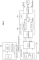
- FIG. 3 is a diagram illustrating a configuration of an apparatus for a fuel cell system according to an embodiment.
- the apparatus for a fuel cell system may further include a fuel cell controller (FCU) 301 for transmitting a control command regarding a hydrogen tank valve HTV1 to a master controller 310.
- FCU fuel cell controller
- the FCU 301 may include a fuel cell control connector for connection to the master controller 310.
- the fuel cell control connector may include a connector or pin port and include a 40-pin connector.
- the FCU 301 may include an MCU, a controller area network (CAN) driver, an interface, etc.
- CAN controller area network
- the master controller 310 may include a master connector 311 for connection to the slave controller 320 or the FCU 301.
- the master connector 311 may include a 40-pin connector.
- the master connector 311 may be connected up to about six to slave controllers or slave modules, and the number of pins of the master connector 311 may actually be increased.
- a master controller may be used as it is by changing only slave controllers.
- the slave controller 320 may include a slave connector for connection to the master controller 310.
- the slave connector may include a 6-pin connector.
- the slave controller 320 may include a hydrogen tank valve connector for connection to the hydrogen tank valve HTV1.
- the hydrogen tank valve connector may include a 4-pin connector.
- the slave controller 320 may include a power regulator, a field-effect transistor (FET) HTV1 FET for the hydrogen tank valve HTV1, a sensor or sensing unit, an MCU 321, etc.
- FET field-effect transistor
- the MCU 321 may be configured to have low specifications and added to a slave controller for more precise control of an HMU or bidirectional checking.
- a signal/control signal generated by the MCU of the FCU 301 may be transmitted/delivered to the master controller 310 through a CAN driver, an interface, or a connector.
- a command to open or close a valve which is delivered by the FCU 301, may be delivered to the MCU of the master controller 310 through a connector (the fuel cell control connector and a master connector).
- the MCU of the master controller 310 may deliver the signal of the pulse width modulation (PWM) to a driver of the master controller 310 or perform control using PWM according to duty.
- the driver of the master controller 310 may transmit a signal output therefrom to the FET of the slave controller 320 through a connector (the master connector and the slave connector).
- the FET of the slave controller 320 may receive and amplify the signal output from the driver.
- the slave controller 320 may receive information or a signal of pressure or temperature of a hydrogen tank/hydrogen tank valve from the hydrogen tank valve HTV1 through a connector (the hydrogen tank valve connector).
- the slave controller 320 may receive, be supplied with or sense current from the FET of the slave controller 320 using a sensor/sensing unit, and transmit/deliver the received/supplied or sensed information/signal to the MCU of the master controller 310 through a connector (the master connector or the slave connector).
- FIG. 4 is a diagram for describing replacement of each module of an apparatus for a fuel cell system according to an embodiment.
- an MCU 401 In the apparatus for a fuel cell system, an MCU 401, an FET 402, a hydrogen tank valve 403, etc. are highly likely to malfunction and each of the modules may be removed and replaced when a fault occurs.
- diagnosing and a fail-safety operation may be simplified and the operation of the decision logic may be accelerated in terms of an FCU.
- the system of the apparatus for a fuel cell system may be easily configured by adding a slave controller (slave HMU) for remaining pins corresponding to the number of hydrogen tanks to be used and modifying only software of the master controller (master HMU).
- slave HMU slave controller
- master HMU master controller
- FIG. 5 is a block diagram of a control device for a fuel cell system according to an embodiment.
- a control device 500 for a fuel cell system may include a master controller 501 for managing the fuel cell system, and at least one slave controller, e.g., slave controllers 502 and 503, for managing a fuel cell of the fuel cell system.
- the control device 500 for a fuel cell system may include at least some of the components of the apparatus for a fuel cell system device described above.
- the slave controllers 502 and 503 may be connected to the master controller 501.
- the slave controllers 502 and 503 may manage valves connected to hydrogen tanks or the hydrogen tanks.
- the slave controllers 502 and 503 may manage the valves or the hydrogen tanks on the basis of the temperature or pressure of the hydrogen tanks.
- the slave controllers 502 and 503 may transmit information about the valves or the hydrogen tanks to the master controller 501.
- the master controller 501 may manage the fuel cell system on the basis of the information about valves or the hydrogen tanks received from the slave controllers 502 and 503.
- control device 500 for a fuel cell system may further include a fuel cell controller (not shown) that delivers a control command regarding the valves to the master controller 501.
- FIG. 6 is a flowchart of a control method of a fuel cell system according to an embodiment.
- operations of the control method of a fuel cell system may be performed by at least some of the components of the control device for a fuel cell system described above.
- control device for a fuel cell system may manage the fuel cell system using a master controller.
- control device for a fuel cell system may manage a fuel cell of the fuel cell system using at least one slave controller.
- the at least one slave controller may be connected to the master controller.
- control device for a fuel cell system may manage a valve connected to a hydrogen tank or the hydrogen tank.
- control device for a fuel cell system may manage a valve or a hydrogen tank on the basis of the temperature or pressure of the hydrogen tank.
- control device for a fuel cell system may transmit information about the valve or the hydrogen tank to the master controller.
- control device for a fuel cell system may manage the fuel cell system on the basis of information about a valve or a hydrogen tank received from a slave controller.
- control device for a fuel cell system may deliver a control command regarding a valve to the master controller using a fuel cell controller.
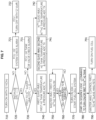
- FIG. 7 is a flowchart of a control method of a fuel cell system according to an embodiment.
- a control device for a fuel cell system may start a fuel cell system.
- 12 V under control of a user or administrator of the fuel cell system may be provided, and the control device for a fuel cell system would turn on at least a part of the fuel cell system with the control.
- control device for a fuel cell system may perform initialization using a master controller (HMU) and may check whether a diagnostic trouble code (DTC) is zero.
- HMU master controller
- DTC diagnostic trouble code
- the control device for a fuel cell system may provide an alarm for checking a hydrogen (H 2 ) system/fuel cell system or deliver/transmit the alarm to a user terminal/administrator terminal using an FCU.
- H 2 hydrogen
- control device for a fuel cell system may turn off at least a part of the fuel cell system with 12 V using an FCU.
- the control device for a fuel cell system may check whether the DTC of the first to n th slave controllers (HMUs) is zero using a master controller (master HMU).
- HMUs slave controllers
- the control device for a fuel cell system may provide an alarm for checking hydrogen tanks or valves connected to the slave controllers having the DTC that is not zero/alarm for a hydrogen tank valve or deliver/transmit the alarm to a user terminal/administrator terminal.
- the control device for a fuel cell system may allow information or a signal about the temperature and pressure of a first hydrogen tank to which the first slave controller is connected to be transmitted to a master controller using an analog-to-digital converter (ADC).
- ADC analog-to-digital converter
- control device for a fuel cell system may allow information or a signal about the temperature and pressure of a second hydrogen tank to which the second slave controller is connected to be transmitted to the master controller using the ADC.
- control device for a fuel cell system may allow information or a signal about the temperature and pressure of a third hydrogen tank to which the third slave controller is connected to be transmitted to the master controller using the ADC.
- the controller device for a fuel cell system may allow the master controller to receive data or information about the first to n th hydrogen tanks connected to the first to n th slave controllers respectively from all of the first to n th slave controllers.
- control device for a fuel cell system may check whether the fuel cell system is ready to be turned on(ON) using an FCU.
- operation 750 may be returned to and operations 750 and 760 may be performed repeatedly.
- the control device for a fuel cell system may start the fuel cell system by turning on an ignition/power device and so on, under control of a user or an administrator.
- control device for a fuel cell system may start an on-sequence logic and transmit a command of ON/OFF to turn on or off the first to n th hydrogen tanks using the FCU.
- control device for a fuel cell system may control FETs of the first to n th slave controllers using the master controller.
- control device for a fuel cell system may turn on a fuel cell under control of the user or administrator.
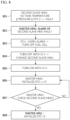
- FIG. 8 is a flowchart of a control method of a fuel cell system according to an embodiment.
- a control device for a fuel cell system may detect or fix/solve the error/problem in a hydrogen tank during an operation of the fuel cell system.
- control device for a fuel cell system may check whether there is a fault in the temperature/pressure/second hydrogen tank valve (or n th hydrogen tank valve) of a second hydrogen tank (or an n th hydrogen tank) using a second slave controller (or an n th slave controller).
- control device for a fuel cell system may provide or transmit an alarm about the fault of the second slave controller (or the n th slave controller) using the master controller.
- control device for a fuel cell system may provide or transmit a (user) alarm and turn off a fuel cell using an FCU.
- control device for a fuel cell system may perform turn off not to apply 12 V under control of the user or administrator and may control the second slave device.
- control device for a fuel cell system may perform turn on to apply 12 V under control of the user or administrator.
- control device for a fuel cell system may perform initialization using the master controller, and set a DTC to a non-zero value.
- control device for a fuel cell system may identify/check the second slave controller using the master controller.
- control device for a fuel cell system may return to operation 806 and perform operations 806 and 807.
- control device for a fuel cell system may perform initialization using the master controller and set the DTC to zero.
- control device for a fuel cell system may perform the start sequence of FIG. 7 .
- unit used in the embodiments set forth herein should be understood to mean a software or hardware component, such as a field-programmable gate array (FPGA) or an application-specific integrated circuit (ASIC), which performs certain functions.
- FPGA field-programmable gate array
- ASIC application-specific integrated circuit
- the term “unit” is not limited to software or hardware.
- a “unit” may be configured to be stored in an addressable storage medium or to reproduce one or more processors.
- the term “unit” may include, for example, components such as software components, object-oriented software components, class components, and task components, processes, functions, attributes, procedures, subroutines, segments of program code, drivers, firmware, microcode, circuits, data, databases, data structures, tables, arrays, and parameters.
- components and functions provided in “units” may be combined into a smaller number of components and “units” or may be divided into sub-components and “subunits.”
- the components and “units” may be implemented to execute one or more CPUs in a device or a secure multimedia card.
Landscapes
- Engineering & Computer Science (AREA)
- General Chemical & Material Sciences (AREA)
- Manufacturing & Machinery (AREA)
- Sustainable Development (AREA)
- Sustainable Energy (AREA)
- Chemical & Material Sciences (AREA)
- Chemical Kinetics & Catalysis (AREA)
- Electrochemistry (AREA)
- Life Sciences & Earth Sciences (AREA)
- Automation & Control Theory (AREA)
- Health & Medical Sciences (AREA)
- Artificial Intelligence (AREA)
- Computing Systems (AREA)
- Evolutionary Computation (AREA)
- Fuzzy Systems (AREA)
- Medical Informatics (AREA)
- Software Systems (AREA)
- Theoretical Computer Science (AREA)
- Fuel Cell (AREA)
Abstract
Description
- This application claims priority to and the benefit of
Korean Patent Application No. 10-2022-0052468, filed on April 28, 2022 - Due to the recent increase in use of fuel cell systems, technology for a control module for a fuel cell system is being studied. However, there is a limit to controlling various types of fuel cell systems by a control method for a fuel cell system of the related art.
- Although research is being conducted to solve problems of the control method of the related art, there are various problems, for example, in redesigning of a relevant control module, and these problems have yet to be solved.
- An embodiment of the present disclosure relates to an apparatus for a fuel cell system and a control device and method for the fuel cell system, and more particularly, to a distributed control module for a fuel cell system.
- An apparatus for a fuel cell system according to an embodiment includes a master controller and at least one slave controller connected to the master controller.
- According to an embodiment, the at least one slave controller may be connected to a valve connected to a hydrogen tank.
- According to an embodiment, the at least one slave controller may include a first slave controller and a second slave controller, the first slave controller may be connected to a first hydrogen tank valve, and the second slave controller may be connected to a second hydrogen tank valve.
- According to an embodiment, the apparatus for a fuel cell system may further include a first hydrogen tank connected to the first hydrogen tank valve, and a second hydrogen tank connected to the second hydrogen tank valve.
- According to an embodiment, the master controller may include a master connector for connection to the at least one slave controller.
- According to an embodiment, the at least one slave controller may include a slave connector for connection to the master controller.
- According to an embodiment, the at least one slave controller may further include a hydrogen tank valve connector for connection to a hydrogen tank valve.
- According to an embodiment, the control device for a fuel cell system may further include a fuel cell controller configured to deliver a control command regarding the hydrogen tank valve to the master controller.
- A control device for a fuel cell system according to an embodiment includes a master controller configured to manage the fuel cell system, and at least one slave controller configured to manage a fuel cell of the fuel cell system, wherein the at least one slave controller is connected to the master controller.
- According to an embodiment, the at least one slave controller may manage a valve connected to a hydrogen tank or the hydrogen tank.
- According to an embodiment, the at least one slave controller may manage the valve or the hydrogen tank on the basis of the temperature or pressure of the hydrogen tank.
- According to an embodiment, the at least one slave controller may transmit information about the valve or the hydrogen tank to the master controller.
- According to an embodiment, the master controller may manage the fuel cell system on the basis of the information about the valve or the hydrogen tank, the information being received from the at least one slave controller.
- According to an embodiment, the apparatus for a fuel cell system may further include a fuel cell controller configured to transmit a control command regarding the valve to the master controller.
- A control method of a fuel cell system according to an embodiment includes managing the fuel cell system using a master controller, and managing a fuel cell of the fuel cell system using at least one slave controller, wherein the at least one slave controller is connected to the master controller.
- According to an embodiment, the managing of the fuel cell may include managing a valve connected to a hydrogen tank or the hydrogen tank.
- According to an embodiment, the managing of the fuel cell may include managing the valve or the hydrogen tank on the basis of the temperature or pressure of the hydrogen tank.
- According to an embodiment, the managing of the fuel cell may include transmitting information about the valve or the hydrogen tank to the master controller.
- According to an embodiment, the managing of the fuel cell system may include managing the fuel cell system on the basis of the information about the valve or the hydrogen tank, the information being received from the at least one slave controller.
- According to an embodiment, the control method may further include transmitting a control command about the valve to the master controller using a fuel cell controller.
- The above and other objects, features and advantages of the present disclosure will become more apparent to those of ordinary skill in the art by describing exemplary embodiments thereof in detail with reference to the accompanying drawings, in which:
-
FIG. 1 is a block diagram of an apparatus for a fuel cell system according to an embodiment; -
FIG. 2 is a diagram illustrating an apparatus for a fuel cell system according to an embodiment; -
FIG. 3 is a diagram illustrating a configuration of an apparatus for a fuel cell system according to an embodiment; -
FIG. 4 is a diagram for describing replacement of each module of an apparatus for a fuel cell system according to an embodiment; -
FIG. 5 is a block diagram of a control device for a fuel cell system according to an embodiment; -
FIG. 6 is a flowchart of a control method of a fuel cell system according to an embodiment; -
FIG. 7 is a flowchart of a control method of a fuel cell system according to an embodiment; and -
FIG. 8 is a flowchart of a control method of a fuel cell system according to an embodiment. - Hereinafter, embodiments of the present disclosure will be described in detail with reference to the accompanying drawings.
- However, the technical idea of the present disclosure is not limited to the embodiments set forth herein and may be implemented in many different forms and one or more components in the embodiments may be selectively combined or replaced with other components without departing from the scope of the present disclosure.
- Unless otherwise defined, all terms (including technical and scientific terms) used in embodiments of the present disclosure have the same meaning as commonly understood by one of ordinary skill in the art to which the present disclosure belongs. It will be understood that terms, such as those defined in commonly used dictionaries, should be interpreted as having a meaning that is consistent with their meaning in the context of the relevant art.
- Terms used in embodiments of the present disclosure are for the purpose of describing the embodiments only and are not intended to be limiting of the present disclosure.
- As used herein, singular forms are intended to include plural forms as well, unless the context clearly indicates otherwise. It will be understood that "at least one of (or at least one or more of) A, B, and C" indicates at least one of all possible combinations of A, B, and C.
- Terms such as "first," "second," "A," "B," "(a)," and "(b)" may be used to describe components of embodiment of the present disclosure.
- Such terms are only for distinguishing one component from another, and the essence, order, or sequence of the components is not limited by the terms.
- When a component is referred to as being "coupled to," "combined with," or "connected to" another component, it will be understood that the component is directly coupled to, combined with or connected to the other component or is coupled to, combined with or connected to the other component through another component interposed therebetween.
- When one component is referred to as being formed or arranged "on (or above)" or "below (or under)" another, it will be understood that the components are in direct contact with each other or one or more components are formed or arranged therebetween. The expression "on (or above)" or "below (or under)" should be understood to include not only an upward direction but also a downward direction with respect to one component.
- Hereinafter, embodiments will be described in detail with reference to the accompanying drawings, but the same or corresponding components are assigned the same reference numbers even in different drawings and are not redundantly described herein.
-
FIG. 1 is a block diagram of an apparatus for a fuel cell system according to an embodiment. - According to an embodiment, the apparatus for a fuel cell system may include a
master controller 110 and at least one slave controller, e.g.,slave controllers - The apparatus for a fuel cell system may include at least a part of a control device for a fuel cell system to be described below. The apparatus for a fuel cell system may include a distributed module for a non-vehicle fuel cell system. The apparatus for a fuel cell system may include a non-vehicle fuel cell system, or is applicable to or usable in a non-vehicle fuel cell system.
- The apparatus for a fuel cell system may include at least a part of the fuel cell system or a fuel cell. The apparatus for a fuel cell system may include at least some of an electrical circuit, an electronic circuit, a communication circuit, a processor, a semiconductor, a memory, a data transceiver, and a valve.
- The apparatus for a fuel cell system may include at least some of all components used herein to describe the present disclosure or perform at least some of all operations/functions of the present disclosure.
- The
slave controllers master controller 110. - According to an embodiment, the
slave controllers hydrogen tank valves - According to an embodiment, slave controllers may include the
first slave controller 121 and the second/nth slave controller 122. n may be a natural number greater than or equal to 2. - The
first slave controller 121 may be connected to the firsthydrogen tank valve 131, and the second/nth slave controller 122 may be connected to the second/nthhydrogen tank valve 132. - According to an embodiment, the apparatus for a fuel cell system may further include a first hydrogen tank (not shown) connected to the first
hydrogen tank valve 131, and a second/nth hydrogen tank (not shown) connected to the second/nthhydrogen tank valve 132. - According to an embodiment, the
master controller 110 may include a master connector for connection to theslave controllers - According to an embodiment, the
slave controllers master controller 110. - According to an embodiment, the
slave controllers hydrogen tank valves - According to an embodiment, the apparatus for a fuel cell system may further include a fuel cell controller (not shown) for transmitting a control command regarding the
hydrogen tank valves master controller 110. - The apparatus for a fuel cell system may be designed as a distributed type and may form a topology.
- The apparatus for a fuel cell system may be divided into a master controller and a slave controller and manufactured as a module type to facilitate scalability.
- In the apparatus for a fuel cell system, only a component that malfunctions may be replaced.
- In the apparatus for a fuel cell system, elements to be modified may be limited as much as possible to replace a centralized hydrogen storage system management unit (HMU) of three hydrogen tanks.
- The apparatus for a fuel cell system is capable of preventing a change of software (SW) and hardware (HW) of balance of plant (BoP).
-
FIG. 2 is a diagram illustrating an apparatus for a fuel cell system according to an embodiment. - The apparatus for a fuel cell system includes a printed circuit board (PCB) having a simpler wiring than a PCB of an existing centralized system and may contribute to reducing the artwork or time. In addition, the apparatus for a fuel cell system may contribute to making a diagnostic system and a fail-safety algorithm for finding problems simpler and easier to understand.
- In the apparatus for a fuel cell system, after-sales service (AS) characteristics are considered, thus reducing replacement costs and time when a problem is found.
- The apparatus for a fuel cell system may be supplied and managed in the form of an assembly of slave controllers and hydrogen tanks, because specifications of the hydrogen tanks may be unified.
- The apparatus for a fuel cell system is classified as a hydrogen-related machine part and thus may be classified as a high-risk product when certified as non-vehicle products, and the number of the possible routes may be increased by adding redundancy to a master-slave structure.
- The apparatus for a fuel cell system is capable of dealing with an unexpected situation on its own. The apparatus for a fuel cell system is capable of detecting an abnormal operation when at least a part of a fuel cell system or fuel cell does not operate normally, and controlling the part to operate normally or shutting off the part having the problem.
- A master controller and a slave controller of the apparatus for a fuel cell system need not be connected to each other via wire. The master controller may include a master HMU, and the slave controller may include a slave HMU
- The master controller and the slave controller may be directly coupled to each other through a connector. The master controller and the slave controller may be connected through a board-to-board (B to B) connector and included in a housing.
- According to an embodiment, the
master controller 210 may include a master connector for connection toslave controllers master controller 210 may include a micro controller unit (MCU), a driver, etc. - According to an embodiment, each of the
slave controllers master controller 210. The slave connector may include a connector or pin port. - According to an embodiment, the
slave controllers -
FIG. 3 is a diagram illustrating a configuration of an apparatus for a fuel cell system according to an embodiment. - The apparatus for a fuel cell system may further include a fuel cell controller (FCU) 301 for transmitting a control command regarding a hydrogen tank valve HTV1 to a
master controller 310. - The
FCU 301 may include a fuel cell control connector for connection to themaster controller 310. The fuel cell control connector may include a connector or pin port and include a 40-pin connector. - The
FCU 301 may include an MCU, a controller area network (CAN) driver, an interface, etc. - The
master controller 310 may include amaster connector 311 for connection to theslave controller 320 or theFCU 301. Themaster connector 311 may include a 40-pin connector. - The
master connector 311 may be connected up to about six to slave controllers or slave modules, and the number of pins of themaster connector 311 may actually be increased. - Even when the size of a hydrogen tank or specifications of a hydrogen tank valve HTV are changed, a master controller may be used as it is by changing only slave controllers.
- The
slave controller 320 may include a slave connector for connection to themaster controller 310. The slave connector may include a 6-pin connector. Theslave controller 320 may include a hydrogen tank valve connector for connection to the hydrogen tank valve HTV1. The hydrogen tank valve connector may include a 4-pin connector. - The
slave controller 320 may include a power regulator, a field-effect transistor (FET) HTV1 FET for the hydrogen tank valve HTV1, a sensor or sensing unit, anMCU 321, etc. - The
MCU 321 may be configured to have low specifications and added to a slave controller for more precise control of an HMU or bidirectional checking. - A signal/control signal generated by the MCU of the
FCU 301 may be transmitted/delivered to themaster controller 310 through a CAN driver, an interface, or a connector. - A command to open or close a valve, which is delivered by the
FCU 301, may be delivered to the MCU of themaster controller 310 through a connector (the fuel cell control connector and a master connector). The MCU of themaster controller 310 may deliver the signal of the pulse width modulation (PWM) to a driver of themaster controller 310 or perform control using PWM according to duty. The driver of themaster controller 310 may transmit a signal output therefrom to the FET of theslave controller 320 through a connector (the master connector and the slave connector). The FET of theslave controller 320 may receive and amplify the signal output from the driver. - The
slave controller 320 may receive information or a signal of pressure or temperature of a hydrogen tank/hydrogen tank valve from the hydrogen tank valve HTV1 through a connector (the hydrogen tank valve connector). Theslave controller 320 may receive, be supplied with or sense current from the FET of theslave controller 320 using a sensor/sensing unit, and transmit/deliver the received/supplied or sensed information/signal to the MCU of themaster controller 310 through a connector (the master connector or the slave connector). -
FIG. 4 is a diagram for describing replacement of each module of an apparatus for a fuel cell system according to an embodiment. - In the apparatus for a fuel cell system, an
MCU 401, anFET 402, ahydrogen tank valve 403, etc. are highly likely to malfunction and each of the modules may be removed and replaced when a fault occurs. - If replacement can be performed in units of modules when the
FET 402 or thehydrogen tank valve 403 malfunctions, diagnosing and a fail-safety operation may be simplified and the operation of the decision logic may be accelerated in terms of an FCU. - To develop a power pack with various specifications, the system of the apparatus for a fuel cell system may be easily configured by adding a slave controller (slave HMU) for remaining pins corresponding to the number of hydrogen tanks to be used and modifying only software of the master controller (master HMU).
-
FIG. 5 is a block diagram of a control device for a fuel cell system according to an embodiment. - According to an embodiment, a
control device 500 for a fuel cell system may include amaster controller 501 for managing the fuel cell system, and at least one slave controller, e.g.,slave controllers - The
control device 500 for a fuel cell system may include at least some of the components of the apparatus for a fuel cell system device described above. - The
slave controllers master controller 501. - According to an embodiment, the
slave controllers - According to an embodiment, the
slave controllers - According to an embodiment, the
slave controllers master controller 501. - According to an embodiment, the
master controller 501 may manage the fuel cell system on the basis of the information about valves or the hydrogen tanks received from theslave controllers - According to an embodiment, the
control device 500 for a fuel cell system may further include a fuel cell controller (not shown) that delivers a control command regarding the valves to themaster controller 501. -
FIG. 6 is a flowchart of a control method of a fuel cell system according to an embodiment. - Referring to
FIG. 6 , operations of the control method of a fuel cell system may be performed by at least some of the components of the control device for a fuel cell system described above. - In
operation 601, the control device for a fuel cell system may manage the fuel cell system using a master controller. - In
operation 602, the control device for a fuel cell system may manage a fuel cell of the fuel cell system using at least one slave controller. - The at least one slave controller may be connected to the master controller.
- According to an embodiment, the control device for a fuel cell system may manage a valve connected to a hydrogen tank or the hydrogen tank.
- According to an embodiment, the control device for a fuel cell system may manage a valve or a hydrogen tank on the basis of the temperature or pressure of the hydrogen tank.
- According to an embodiment, the control device for a fuel cell system may transmit information about the valve or the hydrogen tank to the master controller.
- According to an embodiment, the control device for a fuel cell system may manage the fuel cell system on the basis of information about a valve or a hydrogen tank received from a slave controller.
- According to an embodiment, the control device for a fuel cell system may deliver a control command regarding a valve to the master controller using a fuel cell controller.
-
FIG. 7 is a flowchart of a control method of a fuel cell system according to an embodiment. - In the control method of a fuel cell system, a control device for a fuel cell system may start a fuel cell system.
- In
operation 710, 12 V under control of a user or administrator of the fuel cell system may be provided, and the control device for a fuel cell system would turn on at least a part of the fuel cell system with the control. - In
operation 720, the control device for a fuel cell system may perform initialization using a master controller (HMU) and may check whether a diagnostic trouble code (DTC) is zero. - In
operation 721, when the DTC is not zero, the control device for a fuel cell system may provide an alarm for checking a hydrogen (H2) system/fuel cell system or deliver/transmit the alarm to a user terminal/administrator terminal using an FCU. - In
operation 722, the control device for a fuel cell system may turn off at least a part of the fuel cell system with 12 V using an FCU. - In
operation 730, when the DTC is zero, the control device for a fuel cell system may check whether the DTC of the first to nth slave controllers (HMUs) is zero using a master controller (master HMU). - In
operation 731, when the DTC of at least some of the first to nth slave controllers is not zero, the control device for a fuel cell system may provide an alarm for checking hydrogen tanks or valves connected to the slave controllers having the DTC that is not zero/alarm for a hydrogen tank valve or deliver/transmit the alarm to a user terminal/administrator terminal. - In
operation 740, when a DTC of all of the first to nth slave controllers is zero, the control device for a fuel cell system may allow information or a signal about the temperature and pressure of a first hydrogen tank to which the first slave controller is connected to be transmitted to a master controller using an analog-to-digital converter (ADC). - In
operation 741, the control device for a fuel cell system may allow information or a signal about the temperature and pressure of a second hydrogen tank to which the second slave controller is connected to be transmitted to the master controller using the ADC. - In
operation 742, the control device for a fuel cell system may allow information or a signal about the temperature and pressure of a third hydrogen tank to which the third slave controller is connected to be transmitted to the master controller using the ADC. - In
operation 750, the controller device for a fuel cell system may allow the master controller to receive data or information about the first to nth hydrogen tanks connected to the first to nth slave controllers respectively from all of the first to nth slave controllers. - In
operation 760, the control device for a fuel cell system may check whether the fuel cell system is ready to be turned on(ON) using an FCU. - When the fuel cell system is not ready to be turned on(ON),
operation 750 may be returned to andoperations - In
operation 770, when the fuel cell system is ready to be turned on, the control device for a fuel cell system may start the fuel cell system by turning on an ignition/power device and so on, under control of a user or an administrator. - In
operation 780, the control device for a fuel cell system may start an on-sequence logic and transmit a command of ON/OFF to turn on or off the first to nth hydrogen tanks using the FCU. - In
operation 790, the control device for a fuel cell system may control FETs of the first to nth slave controllers using the master controller. - In
operation 791, the control device for a fuel cell system may turn on a fuel cell under control of the user or administrator. -
FIG. 8 is a flowchart of a control method of a fuel cell system according to an embodiment. - In the control method of a fuel cell system, a control device for a fuel cell system may detect or fix/solve the error/problem in a hydrogen tank during an operation of the fuel cell system.
- In
operation 801, the control device for a fuel cell system may check whether there is a fault in the temperature/pressure/second hydrogen tank valve (or nth hydrogen tank valve) of a second hydrogen tank (or an nth hydrogen tank) using a second slave controller (or an nth slave controller). - In
operation 802, the control device for a fuel cell system may provide or transmit an alarm about the fault of the second slave controller (or the nth slave controller) using the master controller. - In
operation 803, the control device for a fuel cell system may provide or transmit a (user) alarm and turn off a fuel cell using an FCU. - In
operation 804, the control device for a fuel cell system may perform turn off not to apply 12 V under control of the user or administrator and may control the second slave device. - In
operation 805, the control device for a fuel cell system may perform turn on to apply 12 V under control of the user or administrator. - In
operation 806, the control device for a fuel cell system may perform initialization using the master controller, and set a DTC to a non-zero value. - In
operation 807, the control device for a fuel cell system may identify/check the second slave controller using the master controller. - When the second slave controller is not identified/checked, the control device for a fuel cell system may return to
operation 806 and performoperations - In
operation 808, when the second slave controller is identified/checked, the control device for a fuel cell system may perform initialization using the master controller and set the DTC to zero. - Thereafter, the control device for a fuel cell system may perform the start sequence of
FIG. 7 . - The term "unit" used in the embodiments set forth herein should be understood to mean a software or hardware component, such as a field-programmable gate array (FPGA) or an application-specific integrated circuit (ASIC), which performs certain functions. However, the term "unit" is not limited to software or hardware. A "unit" may be configured to be stored in an addressable storage medium or to reproduce one or more processors. Thus, the term "unit" may include, for example, components such as software components, object-oriented software components, class components, and task components, processes, functions, attributes, procedures, subroutines, segments of program code, drivers, firmware, microcode, circuits, data, databases, data structures, tables, arrays, and parameters. Components and functions provided in "units" may be combined into a smaller number of components and "units" or may be divided into sub-components and "subunits." In addition, the components and "units" may be implemented to execute one or more CPUs in a device or a secure multimedia card.
- While the present disclosure has been described above with respect to exemplary embodiments thereof, it should be understood by those of ordinary skill in the art that various changes and modifications may be made without departing from the technical concept and scope of the present disclosure defined in the following claims.
Claims (15)
- An apparatus for a fuel cell system, comprising:a master controller; andat least one slave controller connected to the master controller.
- The apparatus of claim 1, wherein the at least one slave controller is connected to a valve connected to a hydrogen tank.
- The apparatus of claim 1 or 2, wherein the at least one slave controller comprises a first slave controller and a second slave controller,wherein the first slave controller is connected to a first hydrogen tank valve, andthe second slave controller is connected to a second hydrogen tank valve.
- The apparatus of claim 3, further comprising:a first hydrogen tank connected to the first hydrogen tank valve; anda second hydrogen tank connected to the second hydrogen tank valve.
- The apparatus of any one of claims 1 to 4, wherein the master controller comprises a master connector for connection to the at least one slave controller.
- The apparatus of any one of claims 1 to 5, wherein the at least one slave controller further comprises:a slave connector for connection to the master controller; anda hydrogen tank valve connector for connection to a hydrogen tank valve.
- The apparatus of claim 6, further comprising a fuel cell controller configured to deliver a control command regarding the hydrogen tank valve to the master controller.
- A control device for a fuel cell system, comprising:a master controller configured to manage the fuel cell system; andat least one slave controller configured to manage a fuel cell of the fuel cell system,wherein the at least one slave controller is connected to the master controller.
- The control device of claim 8, wherein the at least one slave controller manages a hydrogen tank or a valve connected to the hydrogen tank, and the at least one slave controller manages the valve or the hydrogen tank on the basis of temperature or pressure of the hydrogen tank.
- The control device of claim 9, wherein the at least one slave controller transmits information about the valve or the hydrogen tank to the master controller, and the master controller manages the fuel cell system on the basis of the information about the valve or the hydrogen tank received from the at least one slave controller.
- The control device of claim 9 or 10, further comprising a fuel cell controller configured to transmit a control command regarding the valve to the master controller.
- A control method of a fuel cell system, comprising:managing the fuel cell system using a master controller; andmanaging a fuel cell of the fuel cell system using at least one slave controller,wherein the at least one slave controller is connected to the master controller.
- The control method of claim 12, wherein the managing of the fuel cell comprises managing a hydrogen tank or a valve connected to the hydrogen tank, and the managing of the fuel cell comprises managing the valve or the hydrogen tank on the basis of temperature or pressure of the hydrogen tank.
- The control method of claim 13, wherein the managing of the fuel cell comprises transmitting information about the valve or the hydrogen tank to the master controller, and the managing of the fuel cell system comprises managing the fuel cell system on the basis of the information about the valve or the hydrogen tank received from the at least one slave controller.
- The control method of claim 13 or 14, further comprising transmitting a control command about the valve to the master controller using a fuel cell controller.
Applications Claiming Priority (1)
| Application Number | Priority Date | Filing Date | Title |
|---|---|---|---|
| KR1020220052468A KR102778281B1 (en) | 2022-04-28 | 2022-04-28 | Apparatus for fuel cell system |
Publications (1)
| Publication Number | Publication Date |
|---|---|
| EP4269858A1 true EP4269858A1 (en) | 2023-11-01 |
Family
ID=82656554
Family Applications (1)
| Application Number | Title | Priority Date | Filing Date |
|---|---|---|---|
| EP22186333.5A Pending EP4269858A1 (en) | 2022-04-28 | 2022-07-21 | Apparatus for fuel cell system |
Country Status (5)
| Country | Link |
|---|---|
| US (1) | US12469865B2 (en) |
| EP (1) | EP4269858A1 (en) |
| JP (1) | JP2023164241A (en) |
| KR (1) | KR102778281B1 (en) |
| CN (1) | CN116979095A (en) |
Citations (4)
| Publication number | Priority date | Publication date | Assignee | Title |
|---|---|---|---|---|
| EP1203418B1 (en) * | 1999-05-28 | 2009-11-11 | Relion, Inc. | Fuel cell power systems and methods of controlling a fuel cell power system |
| CN101958423A (en) * | 2010-09-25 | 2011-01-26 | 华为技术有限公司 | Hydrogen supply system, system and method for supplying hydrogen and hydrogen fuel cell system |
| US20200276909A1 (en) * | 2019-02-18 | 2020-09-03 | Nikola Corporation | Communications systems and methods for hydrogen fueling and electric charging |
| KR20220052468A (en) | 2020-10-21 | 2022-04-28 | 현대자동차주식회사 | Vehicle and control method thereof |
Family Cites Families (3)
| Publication number | Priority date | Publication date | Assignee | Title |
|---|---|---|---|---|
| JP5390564B2 (en) * | 2011-06-30 | 2014-01-15 | 本田技研工業株式会社 | Fuel cell system |
| JP6935762B2 (en) * | 2018-02-01 | 2021-09-15 | トヨタ自動車株式会社 | Hydrogen tank control system |
| JP2019219012A (en) * | 2018-06-20 | 2019-12-26 | トヨタ自動車株式会社 | Hydrogen tank control device |
-
2022
- 2022-04-28 KR KR1020220052468A patent/KR102778281B1/en active Active
- 2022-07-21 EP EP22186333.5A patent/EP4269858A1/en active Pending
- 2022-08-19 JP JP2022130979A patent/JP2023164241A/en active Pending
- 2022-08-23 US US17/893,551 patent/US12469865B2/en active Active
- 2022-11-16 CN CN202211438419.6A patent/CN116979095A/en active Pending
Patent Citations (4)
| Publication number | Priority date | Publication date | Assignee | Title |
|---|---|---|---|---|
| EP1203418B1 (en) * | 1999-05-28 | 2009-11-11 | Relion, Inc. | Fuel cell power systems and methods of controlling a fuel cell power system |
| CN101958423A (en) * | 2010-09-25 | 2011-01-26 | 华为技术有限公司 | Hydrogen supply system, system and method for supplying hydrogen and hydrogen fuel cell system |
| US20200276909A1 (en) * | 2019-02-18 | 2020-09-03 | Nikola Corporation | Communications systems and methods for hydrogen fueling and electric charging |
| KR20220052468A (en) | 2020-10-21 | 2022-04-28 | 현대자동차주식회사 | Vehicle and control method thereof |
Also Published As
| Publication number | Publication date |
|---|---|
| JP2023164241A (en) | 2023-11-10 |
| US12469865B2 (en) | 2025-11-11 |
| KR20230152923A (en) | 2023-11-06 |
| KR102778281B1 (en) | 2025-03-11 |
| CN116979095A (en) | 2023-10-31 |
| US20230352710A1 (en) | 2023-11-02 |
Similar Documents
| Publication | Publication Date | Title |
|---|---|---|
| US10579484B2 (en) | Apparatus and method for enhancing reliability of watchdog circuit for controlling central processing device for vehicle | |
| CN106055438B (en) | The method and system of memory bar exception on a kind of quick positioning mainboard | |
| US5519832A (en) | Method and apparatus for displaying module diagnostic results | |
| US5327435A (en) | Method for testing a processor module in a computer system | |
| EP3278185B1 (en) | Method and arrangement for providing redundancy in a vehicle electrical control system | |
| US5747889A (en) | Redundant power supply and storage system | |
| US7827442B2 (en) | Shelf management controller with hardware/software implemented dual redundant configuration | |
| US7028125B2 (en) | Hot-pluggable peripheral input device coupling system | |
| JPH0479005B2 (en) | ||
| EP0176342A2 (en) | Power control network using reliable communications protocol | |
| CN113261396A (en) | Basic module and functional module for a switchgear cabinet system and switchgear cabinet system | |
| US12466376B2 (en) | Switching device for a brake system for a vehicle, brake system with a switching device and method for operating a switching device | |
| US12469865B2 (en) | Apparatus for fuel cell system | |
| US20060271810A1 (en) | Backup control system and method | |
| CN115335263B (en) | Control device for controlling a vehicle function of a vehicle and method for operating a control device | |
| JPH04215140A (en) | Computer apparatus | |
| CN113868037A (en) | System and method for judging cable connection accuracy of hard disk backboard | |
| CN108779876B (en) | Expanding the functionality of process devices | |
| CN224263562U (en) | Test bench of drive-by-wire chassis | |
| CN214151684U (en) | Mainboard assembly with monitoring function and system thereof | |
| US11379297B2 (en) | System and method to provide safety partition for automotive system-on-a-chip | |
| JPH06348613A (en) | Self-diagnostic system for channel board | |
| CN120652859A (en) | Method for monitoring an insertion unit in a rack | |
| CN117826933A (en) | A computing device and a clock configuration method | |
| JPH04218805A (en) | Monitor device for programmable controller |
Legal Events
| Date | Code | Title | Description |
|---|---|---|---|
| PUAI | Public reference made under article 153(3) epc to a published international application that has entered the european phase |
Free format text: ORIGINAL CODE: 0009012 |
|
| STAA | Information on the status of an ep patent application or granted ep patent |
Free format text: STATUS: REQUEST FOR EXAMINATION WAS MADE |
|
| 17P | Request for examination filed |
Effective date: 20220721 |
|
| AK | Designated contracting states |
Kind code of ref document: A1 Designated state(s): AL AT BE BG CH CY CZ DE DK EE ES FI FR GB GR HR HU IE IS IT LI LT LU LV MC MK MT NL NO PL PT RO RS SE SI SK SM TR |
|
| RAP1 | Party data changed (applicant data changed or rights of an application transferred) |
Owner name: KIA CORPORATION Owner name: HYUNDAI MOTOR COMPANY |
|
| RAP3 | Party data changed (applicant data changed or rights of an application transferred) |
Owner name: KIA CORPORATION Owner name: HYUNDAI MOTOR COMPANY |
|
| P01 | Opt-out of the competence of the unified patent court (upc) registered |
Free format text: CASE NUMBER: APP_3823/2025 Effective date: 20250123 |