EP4269812A1 - Hydraulically locking actuator configuration - Google Patents
Hydraulically locking actuator configuration Download PDFInfo
- Publication number
- EP4269812A1 EP4269812A1 EP23169768.1A EP23169768A EP4269812A1 EP 4269812 A1 EP4269812 A1 EP 4269812A1 EP 23169768 A EP23169768 A EP 23169768A EP 4269812 A1 EP4269812 A1 EP 4269812A1
- Authority
- EP
- European Patent Office
- Prior art keywords
- actuator
- hydraulic
- cavity
- controller
- hydraulic line
- Prior art date
- Legal status (The legal status is an assumption and is not a legal conclusion. Google has not performed a legal analysis and makes no representation as to the accuracy of the status listed.)
- Pending
Links
Images


Classifications
-
- B—PERFORMING OPERATIONS; TRANSPORTING
- B64—AIRCRAFT; AVIATION; COSMONAUTICS
- B64C—AEROPLANES; HELICOPTERS
- B64C19/00—Aircraft control not otherwise provided for
-
- F—MECHANICAL ENGINEERING; LIGHTING; HEATING; WEAPONS; BLASTING
- F15—FLUID-PRESSURE ACTUATORS; HYDRAULICS OR PNEUMATICS IN GENERAL
- F15B—SYSTEMS ACTING BY MEANS OF FLUIDS IN GENERAL; FLUID-PRESSURE ACTUATORS, e.g. SERVOMOTORS; DETAILS OF FLUID-PRESSURE SYSTEMS, NOT OTHERWISE PROVIDED FOR
- F15B20/00—Safety arrangements for fluid actuator systems; Applications of safety devices in fluid actuator systems; Emergency measures for fluid actuator systems
- F15B20/002—Electrical failure
-
- F—MECHANICAL ENGINEERING; LIGHTING; HEATING; WEAPONS; BLASTING
- F15—FLUID-PRESSURE ACTUATORS; HYDRAULICS OR PNEUMATICS IN GENERAL
- F15B—SYSTEMS ACTING BY MEANS OF FLUIDS IN GENERAL; FLUID-PRESSURE ACTUATORS, e.g. SERVOMOTORS; DETAILS OF FLUID-PRESSURE SYSTEMS, NOT OTHERWISE PROVIDED FOR
- F15B11/00—Servomotor systems without provision for follow-up action; Circuits therefor
- F15B11/003—Systems with load-holding valves
-
- F—MECHANICAL ENGINEERING; LIGHTING; HEATING; WEAPONS; BLASTING
- F15—FLUID-PRESSURE ACTUATORS; HYDRAULICS OR PNEUMATICS IN GENERAL
- F15B—SYSTEMS ACTING BY MEANS OF FLUIDS IN GENERAL; FLUID-PRESSURE ACTUATORS, e.g. SERVOMOTORS; DETAILS OF FLUID-PRESSURE SYSTEMS, NOT OTHERWISE PROVIDED FOR
- F15B13/00—Details of servomotor systems ; Valves for servomotor systems
- F15B13/02—Fluid distribution or supply devices characterised by their adaptation to the control of servomotors
- F15B13/04—Fluid distribution or supply devices characterised by their adaptation to the control of servomotors for use with a single servomotor
- F15B13/044—Fluid distribution or supply devices characterised by their adaptation to the control of servomotors for use with a single servomotor operated by electrically-controlled means, e.g. solenoids, torque-motors
-
- F—MECHANICAL ENGINEERING; LIGHTING; HEATING; WEAPONS; BLASTING
- F15—FLUID-PRESSURE ACTUATORS; HYDRAULICS OR PNEUMATICS IN GENERAL
- F15B—SYSTEMS ACTING BY MEANS OF FLUIDS IN GENERAL; FLUID-PRESSURE ACTUATORS, e.g. SERVOMOTORS; DETAILS OF FLUID-PRESSURE SYSTEMS, NOT OTHERWISE PROVIDED FOR
- F15B15/00—Fluid-actuated devices for displacing a member from one position to another; Gearing associated therewith
- F15B15/20—Other details, e.g. assembly with regulating devices
- F15B15/26—Locking mechanisms
-
- B—PERFORMING OPERATIONS; TRANSPORTING
- B64—AIRCRAFT; AVIATION; COSMONAUTICS
- B64C—AEROPLANES; HELICOPTERS
- B64C13/00—Control systems or transmitting systems for actuating flying-control surfaces, lift-increasing flaps, air brakes, or spoilers
- B64C13/24—Transmitting means
- B64C13/38—Transmitting means with power amplification
- B64C13/40—Transmitting means with power amplification using fluid pressure
-
- F—MECHANICAL ENGINEERING; LIGHTING; HEATING; WEAPONS; BLASTING
- F15—FLUID-PRESSURE ACTUATORS; HYDRAULICS OR PNEUMATICS IN GENERAL
- F15B—SYSTEMS ACTING BY MEANS OF FLUIDS IN GENERAL; FLUID-PRESSURE ACTUATORS, e.g. SERVOMOTORS; DETAILS OF FLUID-PRESSURE SYSTEMS, NOT OTHERWISE PROVIDED FOR
- F15B2211/00—Circuits for servomotor systems
- F15B2211/30—Directional control
- F15B2211/305—Directional control characterised by the type of valves
- F15B2211/30505—Non-return valves, i.e. check valves
- F15B2211/30515—Load holding valves
-
- F—MECHANICAL ENGINEERING; LIGHTING; HEATING; WEAPONS; BLASTING
- F15—FLUID-PRESSURE ACTUATORS; HYDRAULICS OR PNEUMATICS IN GENERAL
- F15B—SYSTEMS ACTING BY MEANS OF FLUIDS IN GENERAL; FLUID-PRESSURE ACTUATORS, e.g. SERVOMOTORS; DETAILS OF FLUID-PRESSURE SYSTEMS, NOT OTHERWISE PROVIDED FOR
- F15B2211/00—Circuits for servomotor systems
- F15B2211/30—Directional control
- F15B2211/32—Directional control characterised by the type of actuation
- F15B2211/327—Directional control characterised by the type of actuation electrically or electronically
-
- F—MECHANICAL ENGINEERING; LIGHTING; HEATING; WEAPONS; BLASTING
- F15—FLUID-PRESSURE ACTUATORS; HYDRAULICS OR PNEUMATICS IN GENERAL
- F15B—SYSTEMS ACTING BY MEANS OF FLUIDS IN GENERAL; FLUID-PRESSURE ACTUATORS, e.g. SERVOMOTORS; DETAILS OF FLUID-PRESSURE SYSTEMS, NOT OTHERWISE PROVIDED FOR
- F15B2211/00—Circuits for servomotor systems
- F15B2211/80—Other types of control related to particular problems or conditions
- F15B2211/86—Control during or prevention of abnormal conditions
- F15B2211/862—Control during or prevention of abnormal conditions the abnormal condition being electric or electronic failure
- F15B2211/8623—Electric supply failure
-
- F—MECHANICAL ENGINEERING; LIGHTING; HEATING; WEAPONS; BLASTING
- F15—FLUID-PRESSURE ACTUATORS; HYDRAULICS OR PNEUMATICS IN GENERAL
- F15B—SYSTEMS ACTING BY MEANS OF FLUIDS IN GENERAL; FLUID-PRESSURE ACTUATORS, e.g. SERVOMOTORS; DETAILS OF FLUID-PRESSURE SYSTEMS, NOT OTHERWISE PROVIDED FOR
- F15B2211/00—Circuits for servomotor systems
- F15B2211/80—Other types of control related to particular problems or conditions
- F15B2211/86—Control during or prevention of abnormal conditions
- F15B2211/862—Control during or prevention of abnormal conditions the abnormal condition being electric or electronic failure
- F15B2211/8626—Electronic controller failure, e.g. software, EMV, electromagnetic interference
-
- F—MECHANICAL ENGINEERING; LIGHTING; HEATING; WEAPONS; BLASTING
- F15—FLUID-PRESSURE ACTUATORS; HYDRAULICS OR PNEUMATICS IN GENERAL
- F15B—SYSTEMS ACTING BY MEANS OF FLUIDS IN GENERAL; FLUID-PRESSURE ACTUATORS, e.g. SERVOMOTORS; DETAILS OF FLUID-PRESSURE SYSTEMS, NOT OTHERWISE PROVIDED FOR
- F15B2211/00—Circuits for servomotor systems
- F15B2211/80—Other types of control related to particular problems or conditions
- F15B2211/86—Control during or prevention of abnormal conditions
- F15B2211/863—Control during or prevention of abnormal conditions the abnormal condition being a hydraulic or pneumatic failure
- F15B2211/864—Failure of an output member, e.g. actuator or motor failure
-
- F—MECHANICAL ENGINEERING; LIGHTING; HEATING; WEAPONS; BLASTING
- F15—FLUID-PRESSURE ACTUATORS; HYDRAULICS OR PNEUMATICS IN GENERAL
- F15B—SYSTEMS ACTING BY MEANS OF FLUIDS IN GENERAL; FLUID-PRESSURE ACTUATORS, e.g. SERVOMOTORS; DETAILS OF FLUID-PRESSURE SYSTEMS, NOT OTHERWISE PROVIDED FOR
- F15B2211/00—Circuits for servomotor systems
- F15B2211/80—Other types of control related to particular problems or conditions
- F15B2211/875—Control measures for coping with failures
- F15B2211/8752—Emergency operation mode, e.g. fail-safe operation mode
Definitions
- the following description relates to hydraulic actuators and, more particularly, to hydraulic actuator systems that employ hydraulic locking to secure the actuator in a last scheduled position.
- an actuator In many engine actuator applications, an actuator is sent into or positioned in a fail-safe position in an event of an electrical failure.
- This fail-safe position may be an extended or retracted position.
- helicopters the notion of automatically positioning an actuator in a fail-safe position instead of a last-commanded position in the event of an electrical failure might not be desirable because of a need to maintain certain flight control parameters. Indeed, in at least some cases, while it is actually desirable to hold the actuator in the last commanded position instead of the fail-safe position in the event of an electrical failure, the nature of control systems of typical hydraulically powered actuators of helicopters makes doing so difficult. Accordingly, improved actuator systems are desirable.
- hydraulic actuator systems for aircraft include a hydraulic actuator having a housing with a piston arranged within the housing, the piston having a piston head separating the housing into a retract cavity and an extend cavity, an actuator controller hydraulically coupled to the retract cavity by a first hydraulic line and hydraulically coupled to the extend cavity by a second hydraulic line, wherein the actuator controller is configured to control a hydraulic pressure within each of the retract cavity and the extend cavity to control actuation of the hydraulic actuator, and a position-lock controller arranged along at least one of the first hydraulic line and the second hydraulic line, the position-lock controller configured to hydraulically decouple the actuator controller from at least one of the retract cavity and the extend cavity.
- further embodiments of the hydraulic actuator systems may include that the hydraulic decoupling occurs in response to a failure of the hydraulic actuator system.
- further embodiments of the hydraulic actuator systems may include that the failure is a power failure to the hydraulic actuator system.
- further embodiments of the hydraulic actuator systems may include that the position-lock controller is configured to maintain the at least one hydraulic line in an open state until the failure occurs.
- further embodiments of the hydraulic actuator systems may include that the position-lock controller is coupled along both the first hydraulic line and the second hydraulic line.
- further embodiments of the hydraulic actuator systems may include that the position-lock controller is a first position-lock controller arranged along the first hydraulic line, the system further comprising a second position-lock controller arranged along the second hydraulic line.
- further embodiments of the hydraulic actuator systems may include that the position-lock controller comprises a solenoid.
- further embodiments of the hydraulic actuator systems may include that the actuator controller is an electrohydraulic servo valve.
- hydraulic actuator systems may include an aircraft system, wherein the piston is configured to actuate a component of the aircraft system.
- methods of operating hydraulic actuator systems onboard aircraft include controlling hydraulic pressure to a retract cavity from an actuator controller through a first hydraulic line that hydraulically couples the actuator controller to the retract cavity, controlling hydraulic pressure to an extend cavity from the actuator controller through a second hydraulic line that hydraulically couples the actuator controller to the extend cavity, and operating a position-lock controller to hydraulically lock at least one of the retract cavity and the extend cavity, wherein the position-lock controller is arranged along at least one of the first hydraulic line and the second hydraulic line.
- further embodiments of the methods may include that the position-lock controller is operated in response to a failure of the hydraulic actuator system.
- further embodiments of the methods may include that the failure is a power failure to the hydraulic actuator system.
- further embodiments of the methods may include maintaining the at least one hydraulic line in an open state using the position-lock controller until the failure occurs.
- further embodiments of the methods may include that the position-lock controller is coupled along both the first hydraulic line and the second hydraulic line, wherein the position-lock controller is configured to hydraulically lock both the retract cavity and the extend cavity.
- further embodiments of the methods may include that the position-lock controller is a first position-lock controller arranged along the first hydraulic line and configured to hydraulically lock the retract cavity, the method further comprising operating a second position-lock controller arranged along the second hydraulic line and configured to hydraulically lock the extend cavity.
- further embodiments of the methods may include that the position-lock controller comprises a solenoid.
- actuator controller is an electrohydraulic servo valve.
- further embodiments of the methods may include that the position-lock controller is configured to hydraulically lock one of the retract cavity and the extend cavity by decoupling the respective hydraulic line, the method further comprising passing a hydraulic fluid through the other of the extend cavity and the retract cavity that is not hydraulically locked.
- Such actuator systems may be, for example and without limitation, fail-fixed hydraulic actuator systems or position-fixed hydraulic actuator systems.
- Hydraulic actuation systems are useful for high load and slew rate capabilities, but such actuators may tend to revert to an extend or retract stop point at a time of failure, even if the piston of the actuator is not at an end position. That is, in a failure condition, conventional actuators may be biased to one end-stop (e.g., fully retracted or fully extended). However, it may be desirable to have an actuator that remains in a last commanded position despite a failure.
- an actuator that remains in a current position rather than fully extending or fully retracting at a time of failure. Such failures may be the result of power loss, control loop failure, or the like. Additionally, last-commanded-position operation of an actuator system be beneficial outside of failure conditions, such as low pressure conditions which can benefit from allowing for reduced pressure out from a pumping system while maintaining sufficient force at the actuator.
- Actuator systems may be controlled by a servo valve and the actuator is slewed back and forth by a switching of a flow path in the servo valve. This is done by varying current to a torque motor that in one of many ways diverts flow and high pressure to either the extend or retract chamber of the actuator. In the event where the electrical control to the servo valve is lost or failed in one direction it can be beneficial to prevent the actuator from leaving its last scheduled position. By hydraulically locking one or both sides of the actuator chambers this can be efficiently accomplished and used to maintain position of the actuator even under great loads.
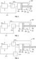
- the actuator system 100 may be used onboard aircraft to perform an actuating operation of an actuator 101 through actuation or movement of a piston 102 within a housing 104.
- the piston 102 includes a piston head 106 that is configured to have hydraulic pressure applied thereto such that the piston head 106 translates or otherwise moves within the housing 104.
- the housing 104 defines a retract cavity 108 and an extend cavity 110 which are defined on opposite sides of the piston head 106.
- the actuator 101 may be coupled to a component and/or system of an aircraft to perform actuation or operation of such component or system.
- Such components or systems can include, without limitation, valves, blades, flight structures (e.g., flaps, slats, etc.), and the like, as will be appreciated by those of skill in the art.
- the retract cavity 108 and the extend cavity are each hydraulically (and/or fluidly) coupled to an actuator controller 112 which can be controlled to increase or decrease a pressure within the cavities 108, 110.
- the actuator controller 112 may be an electrohydraulic servo valve or the like, as will be appreciated by those of skill in the art.
- the retract cavity 108 may be coupled (hydraulically and/or fluidly) to the actuator controller 112 by a first hydraulic line 114.
- the extend cavity 110 may be coupled (hydraulically and/or fluidly) to the actuator controller 112 by a second hydraulic line 116.
- hydraulic pressure is directed from the actuator controller 112 to fill the retract cavity 108 and the extend cavity 110.
- the pressure levels of the two cavities 108, 110 may be adjusted or controlled to control operation and actuation of the piston 102. For example, a low pressure within the retract cavity 108 and high pressure in the extend cavity 110 will cause the piston 102 to retract into the housing 104. Similarly, when the pressure within the extend cavity 110 is lower than the pressure within the retract cavity 108, the piston 102 will be extended outward from the housing 104.
- the pressures within the cavities 108, 110 are controlled by the supply from the actuator controller 112 through the hydraulic lines 114, 116.
- the actuator controller 112 is configured with a supply pressure 118 (e.g., high pressure) and a drain pressure 120 (e.g., low pressure). By regulating and controlling the hydraulic pressure through the hydraulic lines 114, 116, the actuator controller 112 controls operation of the actuator system 100.
- a supply pressure 118 e.g., high pressure
- a drain pressure 120 e.g., low pressure
- the position-lock controller 122 may include one or more solenoids that are configured to selectively connect and disconnect each of the hydraulic lines 114, 116.
- the position-lock controller 122 can include a first selective coupler 124 arranged along the first hydraulic line 114 and a second selective coupler 126 arranged along the second hydraulic line 116.
- FIG. 1A illustrates both the first and second selective couplers 124, 126 in an open position, allowing for hydraulic coupling between the actuator controller 112 and the cavities 108, 110 along the hydraulic lines 114, 116.
- FIG. 1B illustrates both the first and second selective couplers 124, 126 in a closed position, preventing hydraulic coupling between the actuator controller 112 and the cavities 108, 110 along the hydraulic lines 114, 116. That is, the position-lock controller 122 is configured to selectively lock pressures within the cavities 108, 110 to secure the position of the piston 102 and preventing changes in the relatively pressure across the piston head 106.
- the decoupling ( FIG. 1B ) may be initiated or activated in the event of a power failure (or other failure) of the actuator system 100. As such, when power is lost, the actuator system 100 may be fixed in a last commanded position and the piston 102 will not transition to a fully retracted or fully extended position upon such failure.
- the actuator controller 112 is configured to increase or decrease a hydraulic pressure in the cavities 108, 110. This change in hydraulic pressure causes the piston 102 to translate within the housing 104 (i.e., actuate).
- the hydraulic lines 114, 116 are decoupled from the respective cavities 108, 110, thus maintaining the pressure within the cavities 108, 110 at the existing pressure levels at the time of the failure. Accordingly, the piston 102 will be locked into place at the time of the failure.
- the position-lock controller 122 may be a switching solenoid that placed between the controlling actuator controller 112 and the actuator that can deadhead flow into and out of the actuator 101. If the actuator controller 112 fails or runs away in either direction the solenoid may be configured to hydraulically lock both sides of the actuator 101. In some embodiments, rather than locking both sides of the actuator 101 (e.g., decoupling hydraulic coupling to both cavities 108, 110), the position-lock controller 122 may be configured to lock one side of the actuator 101. Such single-sided locking of the actuator 101 may be helpful in a situation where cooling flow is dependent on flow through one of the cavities 108, 110 of the actuator 101.
- FIG. 2 a schematic illustration of an actuator system 200 in accordance with an embodiment of the present disclosure are shown.
- the actuator system 200 is substantially similar to that shown and described above and includes an actuator 201 having a piston 202 within a housing 204.
- the piston 202 includes a piston head 206 that is configured to have hydraulic pressure applied thereto from a retract cavity 208 and an extend cavity 210.
- an actuator controller 212 is hydraulically coupled to the retract cavity 208 by a first hydraulic line 214 and to the extend cavity 210 by a second hydraulic line 216.
- the first hydraulic line 214 is always connected and only the second hydraulic line 216 includes a position-lock controller 218 arranged along the second hydraulic line 216.
- the hydraulic pressure within the extend cavity 210 can be locked, while maintaining the hydraulic connection to the retract cavity 208.
- the hydraulic locking of the extend cavity 210 may be performed to secure the actuator 201 in a last commanded position while also permitting flow through the retract cavity 208, such as for the purpose of passing a cooling flow therethrough or the like.
- FIG. 3 a schematic illustration of an actuator system 300 in accordance with an embodiment of the present disclosure are shown.
- the actuator system 300 is substantially similar to that shown and described above and includes an actuator 301 having a piston 302 within a housing 304.
- the piston 302 includes a piston head 306 that is configured to have hydraulic pressure applied thereto from a retract cavity 308 and an extend cavity 310.
- an actuator controller 312 is hydraulically coupled to the retract cavity 308 by a first hydraulic line 314 and to the extend cavity 310 by a second hydraulic line 316.
- the second hydraulic line 316 is always connected and only the first hydraulic line 314 includes a position-lock controller 318 arranged along the first hydraulic line 316.
- the hydraulic pressure within the retract cavity 308 can be locked, while maintaining the hydraulic connection to the extend cavity 310.
- the hydraulic locking of the retract cavity 308 may be performed to secure the actuator 301 in a last commanded position while also permitting flow through the extend cavity 310, such as for the purpose of passing a cooling flow therethrough or the like.
- the configuration of FIG. 2 may be configured for resisting forces that act to extend the actuator.
- the configuration of FIG. 3 may be configured for resisting forces that act to retract the actuator.
- the solenoid/valve (position-lock controller 218) is only on the retract chamber line (second hydraulic line 216). Because of this, any forces acting in the retract direction may cause vaporization of the fluid and allow for movement of the piston.
- the solenoid/valve (position-lock controller 318) is only on the extend chamber line (first hydraulic line 314). In each case, the respective chamber is held in static pressure due to decoupling of the hydraulic lines, thus preventing a specific directional movement of the respective piston.
- FIG. 4 a schematic illustration of an actuator system 400 in accordance with an embodiment of the present disclosure are shown.
- the actuator system 400 is substantially similar to that shown and described above and includes an actuator 401 having a piston 402 within a housing 404.
- the piston 402 includes a piston head 406 that is configured to have hydraulic pressure applied thereto from a retract cavity 408 and an extend cavity 410.
- an actuator controller 412 is hydraulically coupled to the retract cavity 408 by a first hydraulic line 414 and to the extend cavity 410 by a second hydraulic line 416.
- each of the first hydraulic line 414 and the second hydraulic line 416 are selectively closable.
- each hydraulic line 414, 416 includes a respective position-lock controller 418, 420.
- FIG. 5 a flow process 500 for operating an actuator system in accordance with an embodiment of the present disclosure is shown.
- the flow process 500 is designed for operating an actuator system such as that shown and described above.
- the flow process 500 operation is functional with a hydraulic actuator having a piston actuator arranged within a housing with cavities defined on opposing sides of a piston head.
- an actuator controller is hydraulically coupled to a first cavity of an actuator.
- the first cavity may be a retract cavity of the actuator.
- the coupling may be through a first hydraulic line.
- the actuator controller is a device or system that can increase or decrease a hydraulic pressure through the hydraulic line.
- Such actuator controller may be an electrohydraulic servo valve or the like.
- a second hydraulic line is arranged between the actuator controller and a second cavity of the actuator.
- the second cavity may be an extend cavity of the actuator.
- the first and second cavities are defined on opposing sides of a piston head of a piston of the actuator.
- the actuator controller is configured to control a hydraulic pressure within the second cavity. In combination with control of hydraulic pressure within the first cavity, the actuator controller is configured to control movement of the piston head within a housing of the actuator to control actuation of the actuator.
- a position-lock controller is arranged between the actuator controller and one or both of the actuator cavities along the hydraulic lines.
- a single position-lock controller may be arranged to couple to both the first hydraulic line and the second hydraulic line and may be configured to selectively lock the pressure within each of the cavities of the actuator (e.g., as shown in FIGS. 1A-1B ).
- a position-lock controller may be arranged on only one of the two hydraulic lines (e.g., FIGS. 2-3 ).
- each hydraulic line may include a dedicated or discrete position-lock controller (e.g., FIG. 4 ).
- the position-lock controller is actuated or operated in response to a failure of the actuator.
- the actuation of the position-lock controller may be an actuation of a solenoid in response to a lack of power.
- the failure may be a loss of electrical power to the position-lock controller, to the actuator, to the actuator controller, or to some other systems associated with the actuator.
- the actuation of the position-lock controller may be configured to disconnect or disrupt fluid and/or hydraulic connection from the actuator controller and the respective cavities of the actuator.
- the position-lock controller is positioned to disconnect hydraulic connection between the actuator controller and at least one of the two cavities. That is, when the failure occurs, the position-lock controller is transitioned from an open state (e.g., FIG. 1A ) to a closed state (e.g., FIG. 1B ) at the end of the actuation of block 508. As a result, the piston of the actuator will be hydraulically locked in position. This position may be the last commanded position of the actuator, rather than a fail position where the piston is moved to a fully retracted or fully extended position.
- hydraulic actuators are provided with the ability to lock an actuator in a last commanded position after a detection of a failure to a control and/or in response to a commanded fixed position state.
- Such position locking of the actuator can help prevent damage to the system the actuator is controlling.
- any new or existing actuator can utilize the additional functionality described herein.
- Hydraulicly locking the actuator can also be used to simplify the controlling system for the actuator.
- the actuator may be positioned at some initial stage in flight and held there without the need for continuously supplied flow or pressure.
- removing (stopping) a supplied pressure and flow can prevent any internal leakage or unexpected flow from a pump or the like.
- the actuator can hold a position under greater loads than would be possible with given system pressures.
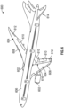
- FIG. 6 illustrates an example of an aircraft 600 having aircraft engines surrounded by (or otherwise carried in) nacelles 602.
- the aircraft 600 includes wings 604 that extend from an aircraft fuselage 606.
- Each wing 604 may include one or more slats 608 on a forward edge or leading edge and one or more flaps 610 on an aft, rear, or trailing edge thereof.
- the wings 604 may also include ailerons 612 on the trailing edges, as will be appreciated by those of skill in the art.
- the aircraft 600 as shown, includes a tail structure 614 which can include various flaps, ailerons, slats, and the like, as will be appreciated by those of skill in the art.
- the flaps, slats, ailerons, and the like are generally referred to herein as "aerostructures" as they are movable under aircraft power systems and are configured to control flight and motion of the aircraft 600.
- An aerostructure actuator system 616 may be connected to one or more of the aerostructures.
- each wing 604 and the tail structure 614 may include one or more aerostructure actuator systems 616.
- the aerostructure actuator systems 616 may be operably connected to the various aerostructures and configured control the operation/position of the aerostructures to control flight of the aircraft 600.
- the aerostructure actuator systems 616 can include one or more actuator systems such as shown and described above with respect to FIGS. 1A-4 .
- the engines of the aircraft 600 may include various actuators and control mechanisms that can incorporate one or more actuator systems such as shown and described above with respect to FIGS. 1A-4 .
- the described actuator systems of the present disclosure may be incorporated into aircraft engine systems and/or aircraft flight systems. It will be appreciated that such actuator systems as described herein may be used for other purposes onboard aircraft, such as for actuating doors, landing gear, or the like.
- embodiments of the present disclosure provide for improved actuators and fixed position operation and control for such actuators.
- one or more position-lock controllers may be actuated or operated to disconnect a hydraulic connection between an actuator controller and cavities of the actuator.
- the actuator will be held in a fixed position due to static pressures in the two cavities of the actuator.
- This advantageously, provides for a non-end stop point of the actuator and allows for the actuator to secure or hold position even against applied forces.
- improved actuators are provided by embodiments of the present disclosure.
- connection can include an indirect “connection” and a direct “connection”.
- each block in the flowchart or block diagrams may represent a module, segment, or portion of instructions, which comprises one or more executable instructions for implementing the specified logical function(s).
- the functions noted in the block may occur out of the order noted in the figures.
- two blocks shown in succession may, in fact, be executed substantially concurrently (or simultaneously), or the blocks may sometimes be executed in the reverse order, depending upon the functionality involved.
Landscapes
- Engineering & Computer Science (AREA)
- Physics & Mathematics (AREA)
- Fluid Mechanics (AREA)
- Mechanical Engineering (AREA)
- General Engineering & Computer Science (AREA)
- Aviation & Aerospace Engineering (AREA)
- Chemical & Material Sciences (AREA)
- Analytical Chemistry (AREA)
- Fluid-Pressure Circuits (AREA)
Abstract
Description
- The following description relates to hydraulic actuators and, more particularly, to hydraulic actuator systems that employ hydraulic locking to secure the actuator in a last scheduled position.
- In many engine actuator applications, an actuator is sent into or positioned in a fail-safe position in an event of an electrical failure. This fail-safe position may be an extended or retracted position. In helicopters, however, the notion of automatically positioning an actuator in a fail-safe position instead of a last-commanded position in the event of an electrical failure might not be desirable because of a need to maintain certain flight control parameters. Indeed, in at least some cases, while it is actually desirable to hold the actuator in the last commanded position instead of the fail-safe position in the event of an electrical failure, the nature of control systems of typical hydraulically powered actuators of helicopters makes doing so difficult. Accordingly, improved actuator systems are desirable.
- According to some aspects of the present disclosure, hydraulic actuator systems for aircraft are provided. The hydraulic actuator systems include a hydraulic actuator having a housing with a piston arranged within the housing, the piston having a piston head separating the housing into a retract cavity and an extend cavity, an actuator controller hydraulically coupled to the retract cavity by a first hydraulic line and hydraulically coupled to the extend cavity by a second hydraulic line, wherein the actuator controller is configured to control a hydraulic pressure within each of the retract cavity and the extend cavity to control actuation of the hydraulic actuator, and a position-lock controller arranged along at least one of the first hydraulic line and the second hydraulic line, the position-lock controller configured to hydraulically decouple the actuator controller from at least one of the retract cavity and the extend cavity.
- In addition to one or more of the features described herein, or as an alternative, further embodiments of the hydraulic actuator systems may include that the hydraulic decoupling occurs in response to a failure of the hydraulic actuator system.
- In addition to one or more of the features described herein, or as an alternative, further embodiments of the hydraulic actuator systems may include that the failure is a power failure to the hydraulic actuator system.
- In addition to one or more of the features described herein, or as an alternative, further embodiments of the hydraulic actuator systems may include that the position-lock controller is configured to maintain the at least one hydraulic line in an open state until the failure occurs.
- In addition to one or more of the features described herein, or as an alternative, further embodiments of the hydraulic actuator systems may include that the position-lock controller is coupled along both the first hydraulic line and the second hydraulic line.
- In addition to one or more of the features described herein, or as an alternative, further embodiments of the hydraulic actuator systems may include that the position-lock controller is a first position-lock controller arranged along the first hydraulic line, the system further comprising a second position-lock controller arranged along the second hydraulic line.
- In addition to one or more of the features described herein, or as an alternative, further embodiments of the hydraulic actuator systems may include that the position-lock controller comprises a solenoid.
- In addition to one or more of the features described herein, or as an alternative, further embodiments of the hydraulic actuator systems may include that the actuator controller is an electrohydraulic servo valve.
- In addition to one or more of the features described herein, or as an alternative, further embodiments of the hydraulic actuator systems may include an aircraft system, wherein the piston is configured to actuate a component of the aircraft system.
- According to some embodiments, methods of operating hydraulic actuator systems onboard aircraft are provided. The methods include controlling hydraulic pressure to a retract cavity from an actuator controller through a first hydraulic line that hydraulically couples the actuator controller to the retract cavity, controlling hydraulic pressure to an extend cavity from the actuator controller through a second hydraulic line that hydraulically couples the actuator controller to the extend cavity, and operating a position-lock controller to hydraulically lock at least one of the retract cavity and the extend cavity, wherein the position-lock controller is arranged along at least one of the first hydraulic line and the second hydraulic line.
- In addition to one or more of the features described herein, or as an alternative, further embodiments of the methods may include that the position-lock controller is operated in response to a failure of the hydraulic actuator system.
- In addition to one or more of the features described herein, or as an alternative, further embodiments of the methods may include that the failure is a power failure to the hydraulic actuator system.
- In addition to one or more of the features described herein, or as an alternative, further embodiments of the methods may include maintaining the at least one hydraulic line in an open state using the position-lock controller until the failure occurs.
- In addition to one or more of the features described herein, or as an alternative, further embodiments of the methods may include that the position-lock controller is coupled along both the first hydraulic line and the second hydraulic line, wherein the position-lock controller is configured to hydraulically lock both the retract cavity and the extend cavity.
- In addition to one or more of the features described herein, or as an alternative, further embodiments of the methods may include that the position-lock controller is a first position-lock controller arranged along the first hydraulic line and configured to hydraulically lock the retract cavity, the method further comprising operating a second position-lock controller arranged along the second hydraulic line and configured to hydraulically lock the extend cavity.
- In addition to one or more of the features described herein, or as an alternative, further embodiments of the methods may include that the position-lock controller comprises a solenoid.
- In addition to one or more of the features described herein, or as an alternative, further embodiments of the methods may include that the actuator controller is an electrohydraulic servo valve.
- In addition to one or more of the features described herein, or as an alternative, further embodiments of the methods may include that the position-lock controller is configured to hydraulically lock one of the retract cavity and the extend cavity by decoupling the respective hydraulic line, the method further comprising passing a hydraulic fluid through the other of the extend cavity and the retract cavity that is not hydraulically locked.
- The foregoing features and elements may be combined in various combinations without exclusivity, unless expressly indicated otherwise. These features and elements as well as the operation thereof will become more apparent in light of the following description and the accompanying drawings. It should be understood, however, the following description and drawings are intended to be illustrative and explanatory in nature and non-limiting.
- The subject matter, which is regarded as the disclosure, is particularly pointed out and distinctly claimed in the claims at the conclusion of the specification. The foregoing and other features, and advantages of the disclosure are apparent from the following detailed description taken in conjunction with the accompanying drawings in which:
-
FIG. 1A is a schematic illustration of an actuator system in accordance with an embodiment of the present disclosure, showing an open state; -
FIG. 1B is a schematic illustration of the actuator system ofFIG. 1A , showing a closed state with an actuator controller decoupled from cavities of a piston actuator; -
FIG. 2 is a schematic illustration of an actuator system in accordance with an embodiment of the present disclosure; -
FIG. 3 is a schematic illustration of and actuator system in accordance with an embodiment of the present disclosure; -
FIG. 4 is a schematic illustration of an actuator system in accordance with an embodiment of the present disclosure; -
FIG. 5 is a flow process for operation of an actuator system in accordance with an embodiment of the present disclosure; and -
FIG. 6 is a schematic illustration of an aircraft that may incorporate embodiments of the present disclosure. - As will be described below, a system and method are provided to allow for tight control of a position in a hydraulically controlled actuator system. Such actuator systems may be, for example and without limitation, fail-fixed hydraulic actuator systems or position-fixed hydraulic actuator systems. Hydraulic actuation systems are useful for high load and slew rate capabilities, but such actuators may tend to revert to an extend or retract stop point at a time of failure, even if the piston of the actuator is not at an end position. That is, in a failure condition, conventional actuators may be biased to one end-stop (e.g., fully retracted or fully extended). However, it may be desirable to have an actuator that remains in a last commanded position despite a failure. That is, it may be beneficial to have an actuator that remains in a current position rather than fully extending or fully retracting at a time of failure. Such failures may be the result of power loss, control loop failure, or the like. Additionally, last-commanded-position operation of an actuator system be beneficial outside of failure conditions, such as low pressure conditions which can benefit from allowing for reduced pressure out from a pumping system while maintaining sufficient force at the actuator.
- Actuator systems may be controlled by a servo valve and the actuator is slewed back and forth by a switching of a flow path in the servo valve. This is done by varying current to a torque motor that in one of many ways diverts flow and high pressure to either the extend or retract chamber of the actuator. In the event where the electrical control to the servo valve is lost or failed in one direction it can be beneficial to prevent the actuator from leaving its last scheduled position. By hydraulically locking one or both sides of the actuator chambers this can be efficiently accomplished and used to maintain position of the actuator even under great loads.
- Referring to
FIGS. 1A-1B , schematic illustrations of anactuator system 100 in accordance with an embodiment of the present disclosure are shown. Theactuator system 100 may be used onboard aircraft to perform an actuating operation of anactuator 101 through actuation or movement of apiston 102 within ahousing 104. Thepiston 102 includes apiston head 106 that is configured to have hydraulic pressure applied thereto such that thepiston head 106 translates or otherwise moves within thehousing 104. Thehousing 104 defines aretract cavity 108 and anextend cavity 110 which are defined on opposite sides of thepiston head 106. Theactuator 101 may be coupled to a component and/or system of an aircraft to perform actuation or operation of such component or system. Such components or systems can include, without limitation, valves, blades, flight structures (e.g., flaps, slats, etc.), and the like, as will be appreciated by those of skill in the art. - To cause movement of the
piston 102 relative to thehousing 104, theretract cavity 108 and the extend cavity are each hydraulically (and/or fluidly) coupled to anactuator controller 112 which can be controlled to increase or decrease a pressure within thecavities actuator controller 112 may be an electrohydraulic servo valve or the like, as will be appreciated by those of skill in the art. For example, the retractcavity 108 may be coupled (hydraulically and/or fluidly) to theactuator controller 112 by a firsthydraulic line 114. Similarly, the extendcavity 110 may be coupled (hydraulically and/or fluidly) to theactuator controller 112 by a secondhydraulic line 116. - In a normal state of operation, hydraulic pressure is directed from the
actuator controller 112 to fill the retractcavity 108 and the extendcavity 110. The pressure levels of the twocavities piston 102. For example, a low pressure within the retractcavity 108 and high pressure in the extendcavity 110 will cause thepiston 102 to retract into thehousing 104. Similarly, when the pressure within the extendcavity 110 is lower than the pressure within the retractcavity 108, thepiston 102 will be extended outward from thehousing 104. The pressures within thecavities actuator controller 112 through thehydraulic lines actuator controller 112 is configured with a supply pressure 118 (e.g., high pressure) and a drain pressure 120 (e.g., low pressure). By regulating and controlling the hydraulic pressure through thehydraulic lines actuator controller 112 controls operation of theactuator system 100. - Arranged along each of the
hydraulic lines lock controller 122. The position-lock controller 122 may include one or more solenoids that are configured to selectively connect and disconnect each of thehydraulic lines lock controller 122 can include a firstselective coupler 124 arranged along the firsthydraulic line 114 and a secondselective coupler 126 arranged along the secondhydraulic line 116.FIG. 1A illustrates both the first and secondselective couplers actuator controller 112 and thecavities hydraulic lines FIG. 1B illustrates both the first and secondselective couplers actuator controller 112 and thecavities hydraulic lines lock controller 122 is configured to selectively lock pressures within thecavities piston 102 and preventing changes in the relatively pressure across thepiston head 106. The decoupling (FIG. 1B ) may be initiated or activated in the event of a power failure (or other failure) of theactuator system 100. As such, when power is lost, theactuator system 100 may be fixed in a last commanded position and thepiston 102 will not transition to a fully retracted or fully extended position upon such failure. - In operation, the
actuator controller 112 is configured to increase or decrease a hydraulic pressure in thecavities piston 102 to translate within the housing 104 (i.e., actuate). When a failure occurs or in response to a command, thehydraulic lines respective cavities cavities piston 102 will be locked into place at the time of the failure. - In this configuration, the position-
lock controller 122 may be a switching solenoid that placed between the controllingactuator controller 112 and the actuator that can deadhead flow into and out of theactuator 101. If theactuator controller 112 fails or runs away in either direction the solenoid may be configured to hydraulically lock both sides of theactuator 101. In some embodiments, rather than locking both sides of the actuator 101 (e.g., decoupling hydraulic coupling to bothcavities 108, 110), the position-lock controller 122 may be configured to lock one side of theactuator 101. Such single-sided locking of theactuator 101 may be helpful in a situation where cooling flow is dependent on flow through one of thecavities actuator 101. - Referring to
FIG. 2 , a schematic illustration of anactuator system 200 in accordance with an embodiment of the present disclosure are shown. Theactuator system 200 is substantially similar to that shown and described above and includes anactuator 201 having apiston 202 within ahousing 204. Thepiston 202 includes apiston head 206 that is configured to have hydraulic pressure applied thereto from a retractcavity 208 and an extendcavity 210. In this embodiment, anactuator controller 212 is hydraulically coupled to the retractcavity 208 by a firsthydraulic line 214 and to the extendcavity 210 by a secondhydraulic line 216. In contrast to the embodiment ofFIGS. 1A-1B , the firsthydraulic line 214 is always connected and only the secondhydraulic line 216 includes a position-lock controller 218 arranged along the secondhydraulic line 216. In this configuration, the hydraulic pressure within the extendcavity 210 can be locked, while maintaining the hydraulic connection to the retractcavity 208. The hydraulic locking of the extendcavity 210 may be performed to secure theactuator 201 in a last commanded position while also permitting flow through the retractcavity 208, such as for the purpose of passing a cooling flow therethrough or the like. - Referring to
FIG. 3 , a schematic illustration of anactuator system 300 in accordance with an embodiment of the present disclosure are shown. Theactuator system 300 is substantially similar to that shown and described above and includes anactuator 301 having apiston 302 within ahousing 304. Thepiston 302 includes apiston head 306 that is configured to have hydraulic pressure applied thereto from a retractcavity 308 and an extendcavity 310. In this embodiment, anactuator controller 312 is hydraulically coupled to the retractcavity 308 by a firsthydraulic line 314 and to the extendcavity 310 by a secondhydraulic line 316. In this embodiment, the secondhydraulic line 316 is always connected and only the firsthydraulic line 314 includes a position-lock controller 318 arranged along the firsthydraulic line 316. In this configuration, the hydraulic pressure within the retractcavity 308 can be locked, while maintaining the hydraulic connection to the extendcavity 310. The hydraulic locking of the retractcavity 308 may be performed to secure theactuator 301 in a last commanded position while also permitting flow through the extendcavity 310, such as for the purpose of passing a cooling flow therethrough or the like. - The configuration of
FIG. 2 may be configured for resisting forces that act to extend the actuator. In contrast, the configuration ofFIG. 3 may be configured for resisting forces that act to retract the actuator. In the embodiment ofFIG. 2 , the solenoid/valve (position-lock controller 218) is only on the retract chamber line (second hydraulic line 216). Because of this, any forces acting in the retract direction may cause vaporization of the fluid and allow for movement of the piston. The opposite is true of the configuration ofFIG. 3 , where the solenoid/valve (position-lock controller 318) is only on the extend chamber line (first hydraulic line 314). In each case, the respective chamber is held in static pressure due to decoupling of the hydraulic lines, thus preventing a specific directional movement of the respective piston. - Referring to
FIG. 4 , a schematic illustration of anactuator system 400 in accordance with an embodiment of the present disclosure are shown. Theactuator system 400 is substantially similar to that shown and described above and includes anactuator 401 having apiston 402 within ahousing 404. Thepiston 402 includes apiston head 406 that is configured to have hydraulic pressure applied thereto from a retractcavity 408 and an extendcavity 410. In this embodiment, anactuator controller 412 is hydraulically coupled to the retractcavity 408 by a firsthydraulic line 414 and to the extendcavity 410 by a secondhydraulic line 416. In this embodiment, each of the firsthydraulic line 414 and the secondhydraulic line 416 are selectively closable. For example, as shown, a first position-lock controller 418 is arranged along the firsthydraulic line 414 and a second position-lock controller 420 is arranged along the secondhydraulic line 416. This configuration is similar to that shown and described above with respect toFIGS. 1A-1B , but rather than a single control valve that is coupled to both hydraulic lines, in this embodiment eachhydraulic line lock controller - The above described and illustrated embodiments are merely for example purposes. It will be appreciated that other various types of connections and components may be employed without departing from the scope of the present disclosure. The specific arrangement of parts and connections may be based on the specific actuator, control mechanisms, system in which the actuator is incorporated, and/or based on the component to be controlled/actuated by the actuator.
- Turning now to
FIG. 5 , aflow process 500 for operating an actuator system in accordance with an embodiment of the present disclosure is shown. Theflow process 500 is designed for operating an actuator system such as that shown and described above. Theflow process 500 operation is functional with a hydraulic actuator having a piston actuator arranged within a housing with cavities defined on opposing sides of a piston head. - At
block 502, an actuator controller is hydraulically coupled to a first cavity of an actuator. The first cavity may be a retract cavity of the actuator. The coupling may be through a first hydraulic line. The actuator controller is a device or system that can increase or decrease a hydraulic pressure through the hydraulic line. Such actuator controller may be an electrohydraulic servo valve or the like. - At
block 504, a second hydraulic line is arranged between the actuator controller and a second cavity of the actuator. The second cavity may be an extend cavity of the actuator. The first and second cavities are defined on opposing sides of a piston head of a piston of the actuator. The actuator controller is configured to control a hydraulic pressure within the second cavity. In combination with control of hydraulic pressure within the first cavity, the actuator controller is configured to control movement of the piston head within a housing of the actuator to control actuation of the actuator. - At
block 506, a position-lock controller is arranged between the actuator controller and one or both of the actuator cavities along the hydraulic lines. In some embodiments, a single position-lock controller may be arranged to couple to both the first hydraulic line and the second hydraulic line and may be configured to selectively lock the pressure within each of the cavities of the actuator (e.g., as shown inFIGS. 1A-1B ). In other embodiments, a position-lock controller may be arranged on only one of the two hydraulic lines (e.g.,FIGS. 2-3 ). In still other embodiments, each hydraulic line may include a dedicated or discrete position-lock controller (e.g.,FIG. 4 ). - At
block 508, the position-lock controller is actuated or operated in response to a failure of the actuator. The actuation of the position-lock controller may be an actuation of a solenoid in response to a lack of power. The failure may be a loss of electrical power to the position-lock controller, to the actuator, to the actuator controller, or to some other systems associated with the actuator. The actuation of the position-lock controller may be configured to disconnect or disrupt fluid and/or hydraulic connection from the actuator controller and the respective cavities of the actuator. - At
block 510, the position-lock controller is positioned to disconnect hydraulic connection between the actuator controller and at least one of the two cavities. That is, when the failure occurs, the position-lock controller is transitioned from an open state (e.g.,FIG. 1A ) to a closed state (e.g.,FIG. 1B ) at the end of the actuation ofblock 508. As a result, the piston of the actuator will be hydraulically locked in position. This position may be the last commanded position of the actuator, rather than a fail position where the piston is moved to a fully retracted or fully extended position. - In accordance with embodiments of the present disclosure, hydraulic actuators are provided with the ability to lock an actuator in a last commanded position after a detection of a failure to a control and/or in response to a commanded fixed position state. Such position locking of the actuator can help prevent damage to the system the actuator is controlling. Advantageously, with very little added complexity any new or existing actuator can utilize the additional functionality described herein. Hydraulicly locking the actuator can also be used to simplify the controlling system for the actuator. For example, in some embodiments, the actuator may be positioned at some initial stage in flight and held there without the need for continuously supplied flow or pressure. Additionally, in some embodiments, removing (stopping) a supplied pressure and flow can prevent any internal leakage or unexpected flow from a pump or the like. Advantageously, by providing the position locking described herein, the actuator can hold a position under greater loads than would be possible with given system pressures.
-
FIG. 6 illustrates an example of an aircraft 600 having aircraft engines surrounded by (or otherwise carried in)nacelles 602. The aircraft 600 includeswings 604 that extend from an aircraft fuselage 606. Eachwing 604 may include one ormore slats 608 on a forward edge or leading edge and one ormore flaps 610 on an aft, rear, or trailing edge thereof. Thewings 604 may also includeailerons 612 on the trailing edges, as will be appreciated by those of skill in the art. The aircraft 600, as shown, includes atail structure 614 which can include various flaps, ailerons, slats, and the like, as will be appreciated by those of skill in the art. The flaps, slats, ailerons, and the like are generally referred to herein as "aerostructures" as they are movable under aircraft power systems and are configured to control flight and motion of the aircraft 600. Anaerostructure actuator system 616 may be connected to one or more of the aerostructures. For example, eachwing 604 and thetail structure 614 may include one or moreaerostructure actuator systems 616. Theaerostructure actuator systems 616 may be operably connected to the various aerostructures and configured control the operation/position of the aerostructures to control flight of the aircraft 600. In some embodiments, theaerostructure actuator systems 616 can include one or more actuator systems such as shown and described above with respect toFIGS. 1A-4 . Further, the engines of the aircraft 600 may include various actuators and control mechanisms that can incorporate one or more actuator systems such as shown and described above with respect toFIGS. 1A-4 . As such, the described actuator systems of the present disclosure may be incorporated into aircraft engine systems and/or aircraft flight systems. It will be appreciated that such actuator systems as described herein may be used for other purposes onboard aircraft, such as for actuating doors, landing gear, or the like. - Advantageously, embodiments of the present disclosure provide for improved actuators and fixed position operation and control for such actuators. In accordance with embodiments of the present disclosure, upon failure of the actuator and/or power thereto, one or more position-lock controllers may be actuated or operated to disconnect a hydraulic connection between an actuator controller and cavities of the actuator. When the hydraulic connection is severed, the actuator will be held in a fixed position due to static pressures in the two cavities of the actuator. This, advantageously, provides for a non-end stop point of the actuator and allows for the actuator to secure or hold position even against applied forces. As such, improved actuators are provided by embodiments of the present disclosure.
- The terms "about" and "substantially" are intended to include the degree of error associated with measurement of the particular quantity based upon the equipment available at the time of filing the application. For example, "about" can include a range of ± 8% or 5%, or 2% of a given value.
- Additionally, the term "exemplary" is used herein to mean "serving as an example, instance or illustration." Any embodiment or design described herein as "exemplary" is not necessarily to be construed as preferred or advantageous over other embodiments or designs. The terms "at least one" and "one or more" are understood to include any integer number greater than or equal to one, i.e., one, two, three, four, etc. The term "a plurality" is understood to include any integer number greater than or equal to two, i.e., two, three, four, five, etc. The term "connection" can include an indirect "connection" and a direct "connection".
- The terminology used herein is for the purpose of describing particular embodiments only and is not intended to be limiting of the disclosure. As used herein, the singular forms "a", "an" and "the" are intended to include the plural forms as well, unless the context clearly indicates otherwise. It will be further understood that the terms "comprises" and/or "comprising," when used in this specification, specify the presence of stated features, integers, steps, operations, elements, and/or components, but do not preclude the presence or addition of one or more other features, integers, steps, operations, element components, and/or groups thereof.
- The flowchart and block diagrams in the Figures illustrate the architecture, functionality, and operation of possible implementations of systems, methods, and computer program products according to various embodiments of the present invention. In this regard, each block in the flowchart or block diagrams may represent a module, segment, or portion of instructions, which comprises one or more executable instructions for implementing the specified logical function(s). In some alternative implementations, the functions noted in the block may occur out of the order noted in the figures. For example, two blocks shown in succession may, in fact, be executed substantially concurrently (or simultaneously), or the blocks may sometimes be executed in the reverse order, depending upon the functionality involved. It is also noted that each block of the block diagrams and/or flowchart illustration, and combinations of blocks in the block diagrams and/or flowchart illustration, can be implemented by special purpose hardware-based systems that perform the specified functions or acts or carry out combinations of special purpose hardware and computer instructions.
- While the disclosure is provided in detail in connection with only a limited number of embodiments, it should be readily understood that the disclosure is not limited to such disclosed embodiments. Rather, the disclosure can be modified to incorporate any number of variations, alterations, substitutions or equivalent arrangements not heretofore described, but which are commensurate with the spirit and scope of the disclosure. Additionally, while various embodiments of the disclosure have been described, it is to be understood that the exemplary embodiment(s) may include only some of the described exemplary aspects. Accordingly, the disclosure is not to be seen as limited by the foregoing description but is only limited by the scope of the appended claims.
Claims (15)
- A hydraulic actuator system of an aircraft, the hydraulic actuator system comprising:a hydraulic actuator (101, 201, 301) having a housing with a piston arranged within the housing, the piston having a piston head separating the housing into a retract cavity and an extend cavity;an actuator controller (112) hydraulically coupled to the retract cavity by a first hydraulic line and hydraulically coupled to the extend cavity by a second hydraulic line, wherein the actuator controller (112) is configured to control a hydraulic pressure within each of the retract cavity and the extend cavity to control actuation of the hydraulic actuator (101, 201, 301); anda position-lock controller (122) along at least one of the first hydraulic line and the second hydraulic line, the position-lock controller (122) configured to hydraulically decouple the actuator controller (112) from at least one of the retract cavity and the extend cavity.
- The hydraulic actuator system of claim 1, wherein the hydraulic decoupling occurs in response to a failure of the hydraulic actuator system.
- The hydraulic actuator system of claim 2, wherein the failure is a power failure to the hydraulic actuator system.
- The hydraulic actuator system of claim 2, wherein the position-lock controller (122) is configured to maintain the at least one hydraulic line in an open state until the failure occurs.
- The hydraulic actuator system of any preceding claim, wherein the position-lock controller (122) coupled along both the first hydraulic line and the second hydraulic line.
- The hydraulic actuator system of any preceding claim, wherein the position-lock controller (122) is a first position-lock controller arranged along the first hydraulic line, the system further comprising a second position-lock controller arranged along the second hydraulic line, or wherein the position-lock controller comprises a solenoid, or wherein the actuator controller (112) is an electrohydraulic servo valve.
- The hydraulic actuator system of any preceding claim, further comprising an aircraft system, wherein the piston is configured to actuate a component of the aircraft system.
- A method of operating a hydraulic actuator system onboard an aircraft, the method comprising:controlling hydraulic pressure to a retract cavity from an actuator controller (112) through a first hydraulic line that hydraulically couples the actuator controller (112) to the retract cavity;controlling hydraulic pressure to an extend cavity from the actuator controller (112) through a second hydraulic line that hydraulically couples the actuator controller (112) to the extend cavity; andoperating a position-lock controller to hydraulically lock at least one of the retract cavity and the extend cavity, wherein the position-lock controller is arranged along at least one of the first hydraulic line and the second hydraulic line.
- The method of claim 8, wherein the position-lock controller is operated in response to a failure of the hydraulic actuator system, and optionally wherein the failure is a power failure to the hydraulic actuator system.
- The method of claim 9, further comprising maintaining the at least one hydraulic line in an open state using the position-lock controller (122) until the failure occurs.
- The method of any of claims 8 to 10, wherein the position-lock controller is coupled along both the first hydraulic line and the second hydraulic line, wherein the position-lock controller is configured to hydraulically lock both the retract cavity and the extend cavity.
- The method of any of claims 8 to 11, wherein the position-lock controller is a first position-lock controller arranged along the first hydraulic line and configured to hydraulically lock the retract cavity, the method further comprising operating a second position-lock controller arranged along the second hydraulic line and configured to hydraulically lock the extend cavity.
- The method of any of claims 8 to 12, wherein the position-lock controller comprises a solenoid.
- The method of any of claims 8 to 13, wherein the actuator controller (112) is an electrohydraulic servo valve.
- The method of any of claims 8 to 14, wherein the position-lock controller is configured to hydraulically lock one of the retract cavity and the extend cavity by decoupling the respective hydraulic line, the method further comprising passing a hydraulic fluid through the other of the extend cavity and the retract cavity that is not hydraulically locked.
Applications Claiming Priority (1)
| Application Number | Priority Date | Filing Date | Title |
|---|---|---|---|
| US17/728,002 US11851163B2 (en) | 2022-04-25 | 2022-04-25 | Hydraulically locking actuator configuration |
Publications (1)
| Publication Number | Publication Date |
|---|---|
| EP4269812A1 true EP4269812A1 (en) | 2023-11-01 |
Family
ID=86226370
Family Applications (1)
| Application Number | Title | Priority Date | Filing Date |
|---|---|---|---|
| EP23169768.1A Pending EP4269812A1 (en) | 2022-04-25 | 2023-04-25 | Hydraulically locking actuator configuration |
Country Status (2)
| Country | Link |
|---|---|
| US (1) | US11851163B2 (en) |
| EP (1) | EP4269812A1 (en) |
Citations (3)
| Publication number | Priority date | Publication date | Assignee | Title |
|---|---|---|---|---|
| US20040245386A1 (en) * | 2003-06-03 | 2004-12-09 | Huynh Neal V. | Systems, apparatuses, and methods for moving aircraft control surfaces |
| US20190203743A1 (en) * | 2017-12-29 | 2019-07-04 | Microtecnica S.R.L. | Hydraulic no-back device |
| EP3514056A1 (en) * | 2018-01-18 | 2019-07-24 | The Boeing Company | Distributed trailing edge wing flap systems |
Family Cites Families (15)
| Publication number | Priority date | Publication date | Assignee | Title |
|---|---|---|---|---|
| US4375780A (en) | 1980-01-28 | 1983-03-08 | General Electric Company | Fail-fixed electrohydraulic servosystem |
| US4343454A (en) | 1980-06-26 | 1982-08-10 | General Electric Company | Apparatus for individual isolation of hydraulically actuated valves |
| US5197516A (en) | 1992-05-01 | 1993-03-30 | Moog Controls, Inc. | Hydraulic servo valve with controlled disengagement feature |
| FR2760718B1 (en) * | 1997-03-14 | 1999-05-28 | Aerospatiale | METHOD AND DEVICE FOR CONTROLLING A TILT OR DEPTH GOVERNOR OF AN AIRCRAFT |
| US5950427A (en) | 1997-11-18 | 1999-09-14 | Worcester Controls Licensco, Inc. | Fail-safe electric hydraulic actuator |
| US7836676B2 (en) | 2007-06-04 | 2010-11-23 | Honeywell International Inc. | Fuel metering valve back-up position control system |
| US8201856B2 (en) | 2008-08-26 | 2012-06-19 | The Boeing Company | Flush-mounted latching assembly |
| CN102464200A (en) * | 2010-11-05 | 2012-05-23 | 江苏海陵机械有限公司 | Aviation building tray stopper driving device |
| US8831848B2 (en) | 2012-05-25 | 2014-09-09 | Gm Global Technology Operations, Llc | Electro-hydraulic clutch system |
| US11137000B2 (en) | 2014-10-10 | 2021-10-05 | MEA Inc. | Self-contained energy efficient hydraulic actuator system |
| EP3228853B1 (en) | 2016-04-08 | 2021-03-10 | Goodrich Actuation Systems Limited | Thrust reverser actuator |
| US10619654B2 (en) * | 2017-05-05 | 2020-04-14 | Hamilton Sundstrand Corporation | Fail-fixed hydraulic actuator |
| EP3431831B1 (en) | 2017-07-19 | 2022-06-08 | Transmisiones y Equipos Mecánicos, S.A. de C.V. | Parking lock actuation system and automatic gearbox for a vehicle |
| EP3693616A1 (en) | 2019-02-11 | 2020-08-12 | Goodrich Actuation Systems SAS | Actuator control valve arrangement |
| DE102019107976B3 (en) * | 2019-03-28 | 2020-07-09 | Alfred-Wegener-Institut, Helmholtz-Zentrum für Polar- und Meeresforschung | Maneuverable measuring body for determining measurement data with malfunction module |
-
2022
- 2022-04-25 US US17/728,002 patent/US11851163B2/en active Active
-
2023
- 2023-04-25 EP EP23169768.1A patent/EP4269812A1/en active Pending
Patent Citations (3)
| Publication number | Priority date | Publication date | Assignee | Title |
|---|---|---|---|---|
| US20040245386A1 (en) * | 2003-06-03 | 2004-12-09 | Huynh Neal V. | Systems, apparatuses, and methods for moving aircraft control surfaces |
| US20190203743A1 (en) * | 2017-12-29 | 2019-07-04 | Microtecnica S.R.L. | Hydraulic no-back device |
| EP3514056A1 (en) * | 2018-01-18 | 2019-07-24 | The Boeing Company | Distributed trailing edge wing flap systems |
Also Published As
| Publication number | Publication date |
|---|---|
| US11851163B2 (en) | 2023-12-26 |
| US20230339603A1 (en) | 2023-10-26 |
Similar Documents
| Publication | Publication Date | Title |
|---|---|---|
| EP3447315B1 (en) | Dual valve systems for actuator control | |
| EP4265921A1 (en) | Hydraulic actuator including a multi-head piston for hydraulic gearing | |
| US20040245386A1 (en) | Systems, apparatuses, and methods for moving aircraft control surfaces | |
| EP3290332B1 (en) | Propeller pitch control actuation system | |
| CN110304238B (en) | Distributed trailing edge wing flap system | |
| JPH0539093A (en) | Hydraulic actuater in hydrostatic mode functional preferably in emergency and steering system provided with said actuator | |
| US12345216B2 (en) | Limited flow thrust reverser actuating | |
| CN111550468B (en) | Actuator control valve arrangement | |
| AU2019268152B2 (en) | Bootstrap hydraulic reservoir | |
| US10458557B2 (en) | Hydraulic actuator force fight mitigation mechanism | |
| EP4265924A1 (en) | Actuator with end stop valve | |
| CN112238935B (en) | Actuator control arrangement | |
| US11851163B2 (en) | Hydraulically locking actuator configuration | |
| EP4269811B1 (en) | Fail-fixed hydraulic actuator | |
| CN114829789B (en) | Fail-safe electro-hydraulic servo valve | |
| EP4542058A1 (en) | Three way transfer valve for parallel electrohydraulic servo valve control of actuator | |
| US12392361B1 (en) | Cross-bleed safety mechanism for a linear hydraulic actuator | |
| US9260179B2 (en) | Propeller and system of counter-rotating propellers comprising improved means for limiting pitch, and a turbine engine comprising them | |
| CN112208745A (en) | hydraulic actuation system | |
| EP4542057A1 (en) | Parallel electrohydraulic servo valve controlled actuator with failure accommodation | |
| US12145719B2 (en) | Hydraulic actuator including a multi-head piston for hydraulic gearing | |
| BR102015011738A2 (en) | hydraulically actuated mechanical lock assembly, and thrust reverser system for an aircraft | |
| CN119551180A (en) | Aircraft wing folding system and control method thereof | |
| DE102017127784A1 (en) | Electrohydraulic reserve module for the emergency supply of hydraulic consumers of an aircraft | |
| CN118302607A (en) | Alleviation of hydraulic force disputes |
Legal Events
| Date | Code | Title | Description |
|---|---|---|---|
| PUAI | Public reference made under article 153(3) epc to a published international application that has entered the european phase |
Free format text: ORIGINAL CODE: 0009012 |
|
| STAA | Information on the status of an ep patent application or granted ep patent |
Free format text: STATUS: THE APPLICATION HAS BEEN PUBLISHED |
|
| AK | Designated contracting states |
Kind code of ref document: A1 Designated state(s): AL AT BE BG CH CY CZ DE DK EE ES FI FR GB GR HR HU IE IS IT LI LT LU LV MC ME MK MT NL NO PL PT RO RS SE SI SK SM TR |
|
| STAA | Information on the status of an ep patent application or granted ep patent |
Free format text: STATUS: REQUEST FOR EXAMINATION WAS MADE |
|
| 17P | Request for examination filed |
Effective date: 20240429 |
|
| RBV | Designated contracting states (corrected) |
Designated state(s): AL AT BE BG CH CY CZ DE DK EE ES FI FR GB GR HR HU IE IS IT LI LT LU LV MC ME MK MT NL NO PL PT RO RS SE SI SK SM TR |
|
| STAA | Information on the status of an ep patent application or granted ep patent |
Free format text: STATUS: EXAMINATION IS IN PROGRESS |
|
| 17Q | First examination report despatched |
Effective date: 20241002 |