EP4269716A1 - Roof window comprising one or more holding members - Google Patents
Roof window comprising one or more holding members Download PDFInfo
- Publication number
- EP4269716A1 EP4269716A1 EP22169650.3A EP22169650A EP4269716A1 EP 4269716 A1 EP4269716 A1 EP 4269716A1 EP 22169650 A EP22169650 A EP 22169650A EP 4269716 A1 EP4269716 A1 EP 4269716A1
- Authority
- EP
- European Patent Office
- Prior art keywords
- frame
- holding
- roof window
- glass sheet
- glass unit
- Prior art date
- Legal status (The legal status is an assumption and is not a legal conclusion. Google has not performed a legal analysis and makes no representation as to the accuracy of the status listed.)
- Granted
Links
Images


Classifications
-
- E—FIXED CONSTRUCTIONS
- E04—BUILDING
- E04D—ROOF COVERINGS; SKY-LIGHTS; GUTTERS; ROOF-WORKING TOOLS
- E04D13/00—Special arrangements or devices in connection with roof coverings; Protection against birds; Roof drainage ; Sky-lights
- E04D13/03—Sky-lights; Domes; Ventilating sky-lights
- E04D13/0305—Supports or connecting means for sky-lights of flat or domed shape
- E04D13/031—Supports or connecting means for sky-lights of flat or domed shape characterised by a frame for connection to an inclined roof
-
- E—FIXED CONSTRUCTIONS
- E04—BUILDING
- E04D—ROOF COVERINGS; SKY-LIGHTS; GUTTERS; ROOF-WORKING TOOLS
- E04D13/00—Special arrangements or devices in connection with roof coverings; Protection against birds; Roof drainage ; Sky-lights
- E04D13/03—Sky-lights; Domes; Ventilating sky-lights
- E04D13/035—Sky-lights; Domes; Ventilating sky-lights characterised by having movable parts
- E04D13/0351—Sky-lights; Domes; Ventilating sky-lights characterised by having movable parts the parts pivoting about a fixed axis
- E04D13/0354—Sky-lights; Domes; Ventilating sky-lights characterised by having movable parts the parts pivoting about a fixed axis the parts being flat
-
- E—FIXED CONSTRUCTIONS
- E06—DOORS, WINDOWS, SHUTTERS, OR ROLLER BLINDS IN GENERAL; LADDERS
- E06B—FIXED OR MOVABLE CLOSURES FOR OPENINGS IN BUILDINGS, VEHICLES, FENCES OR LIKE ENCLOSURES IN GENERAL, e.g. DOORS, WINDOWS, BLINDS, GATES
- E06B3/00—Window sashes, door leaves, or like elements for closing wall or like openings; Layout of fixed or moving closures, e.g. windows in wall or like openings; Features of rigidly-mounted outer frames relating to the mounting of wing frames
- E06B3/66—Units comprising two or more parallel glass or like panes permanently secured together
- E06B3/6617—Units comprising two or more parallel glass or like panes permanently secured together one of the panes being larger than another
-
- E—FIXED CONSTRUCTIONS
- E06—DOORS, WINDOWS, SHUTTERS, OR ROLLER BLINDS IN GENERAL; LADDERS
- E06B—FIXED OR MOVABLE CLOSURES FOR OPENINGS IN BUILDINGS, VEHICLES, FENCES OR LIKE ENCLOSURES IN GENERAL, e.g. DOORS, WINDOWS, BLINDS, GATES
- E06B3/00—Window sashes, door leaves, or like elements for closing wall or like openings; Layout of fixed or moving closures, e.g. windows in wall or like openings; Features of rigidly-mounted outer frames relating to the mounting of wing frames
- E06B3/54—Fixing of glass panes or like plates
- E06B3/5481—Fixing of glass panes or like plates by means of discrete fixing elements, e.g. glazing clips, glaziers points
-
- E—FIXED CONSTRUCTIONS
- E06—DOORS, WINDOWS, SHUTTERS, OR ROLLER BLINDS IN GENERAL; LADDERS
- E06B—FIXED OR MOVABLE CLOSURES FOR OPENINGS IN BUILDINGS, VEHICLES, FENCES OR LIKE ENCLOSURES IN GENERAL, e.g. DOORS, WINDOWS, BLINDS, GATES
- E06B3/00—Window sashes, door leaves, or like elements for closing wall or like openings; Layout of fixed or moving closures, e.g. windows in wall or like openings; Features of rigidly-mounted outer frames relating to the mounting of wing frames
- E06B3/66—Units comprising two or more parallel glass or like panes permanently secured together
- E06B3/6621—Units comprising two or more parallel glass or like panes permanently secured together with special provisions for fitting in window frames or to adjacent units; Separate edge protecting strips
Definitions
- roof windows for installation in a roof structure of a building are popular, since such roof windows may provide e.g. increased/desired inflow of natural light/sunlight, help to provide heating, provide ventilation options and/or the like.
- roof windows may require a more complex window design in order to for example assure sufficient water tightening.
- Patent document US 5 355 644 discloses a roof window comprising a glass unit, a sash member, a glass retaining member and gaskets. This solution may e.g. suffer from aesthetic disadvantages.
- Patent document EP 3 677 734 discloses another solution where a holding part extends in between glass sheets of an insulating glass unit. This solution may suffer from drawbacks with regard to functionalities of the window, heat insulation performance and/or aesthetic disadvantages.
- the present disclosure provides a solution that may solve one or more of the above mentioned drawbacks and e.g. provide an aesthetically desirable, energy efficient and yet user friendly solution.
- the present disclosure relates to a roof window for installation in a roof structure of a building.
- the roof window comprises a frame arrangement comprising structural elongated frame profiles that encloses a frame opening.
- the frame profiles each comprises a first exterior side facing the frame opening and a second exterior side facing away from the frame opening.
- the roof window also comprises one or more holding members comprising a holding part, a wall part, and a fixation part.
- the roof window comprises an insulating glass unit comprising at least a first glass sheet and a second glass sheet. An insulating gap is provided between a major surface of the first glass sheet which faces the insulating gap and a major surface of the second glass sheet which faces the insulating gap.
- the insulating gap is sealed by means of an edge seal arranged between said major surface of the first glass sheet and said major surface of the second glass sheet.
- a side portion of the major surface of the second glass sheet extends with a distance past a part of the edge seal that faces away from the insulating gap so as to provide a space opposite to said side portion and where the space is located opposite to said part of the edge seal.
- the frame arrangement supports the insulating glass unit and the insulating glass unit overlaps one or more of the frame profiles.
- the wall part overlaps a side edge of the second glass sheet.
- the fixation part overlaps the second exterior side of the overlapped frame profile and is attached to the overlapped frame profile at the second exterior side.
- the holding part extends into the space and provides a holding force towards the side portion so as to secure the insulating glass unit at the frame arrangement.
- the present disclosure provides a solution where aesthetical advantages are obtainable as the outer surface of the first glass sheet that faces away from the insulating gap may hence be un-overlapped by the holding member while still providing a good fixation of the frame arrangement.
- the solution provides a reliable assembly of roof windows with glazing units which are exposed to more heat and thermal expansion/creep and also need to be watertight.
- the solution may help to provide a simplified frame design that may user friendly.
- the present disclosure may also provide advantages in relation to obtaining a mechanically simple, yet user friendly, solution for enabling adjusting/adapting the holding force at the side portion.
- Side part(s) of the insulating glass unit that comprises the elongated space may hence overlap the frame profile in the width direction of the frame profile, and the outermost part of the side part(s) of the insulating glass unit that overlaps the frame profile comprises the elongated space that receives the holding part.
- a resilient gasket is preferably placed sandwiched between the interior major surface of the insulating glass unit and surface of the overlapped frame member that faces towards the interior major surface of the insulating glass unit, and this gasket may in preferred embodiments of the present disclosure be compressed due to the holding force.
- the fixation part is attached to the overlapped frame profile at the second exterior side by means of mechanical fastening means.
- Such mechanical fastening means may e.g. help to enable advantageous replacement of the insulating glass unit.
- said mechanical fastening means may comprise one or more screws, clips and/or pop rivets.
- the mechanical fastening means may comprise a fastening member, such as an elongated fastening member, for engaging with the overlapped frame profile.
- the fastening member may here extend in an insertion direction, and the insertion direction may extend with an acute angle relative to a plane defined by the interior major surface of the insulating glass unit facing the frame opening, in a direction away from the plane.
- the direction may be towards a surface part of the second exterior side.
- the insertion direction is (partly) in a direction away from a plane defined by the interior major surface and in a direction away from the insulating glass unit. This may e.g. enable providing a gradual increase or decrease in the holding force dependent on how much the fastening means are "tightened” or displaced.
- the fastening member is preferably, in embodiments of the present disclosure, placed opposite to the interior major surface of the insulating glass unit.
- the insertion direction may also allow better access to the fastening member to allow subsequent replacement of the insulated glass unit - after the roof window is installed into the roof construction where tool access may be limited. This may for example, in some situations, be relevant if the roof window is of the type where the insulated/insulating glass unit is unmovable attached to a fixation frame not comprising a movable frame.
- the access to the fastening member may be covered - for example by a frame part.
- Another advantage of the insertion direction when/if the fastener is a screw may be that it may provide a higher strength when screwed diagonally into the frame.
- the mechanical fastening means may comprise manipulation means for operating the mechanical fastening means, wherein the interior major surface of the insulating glass unit overlaps the fastening member manipulation means.
- the insulating glass unit such as the interior major surface of the insulating glass unit overlaps the entire fastening part so that the fastening part do not extend beyond the edge of the first and/or second glass sheet.
- the interior major surface of the insulating glass unit preferably also overlaps the manipulation means.
- the manipulation means may comprise or be a screw head.
- the manipulation means may in embodiments of the present disclosure be configured to be manipulated by means of a tool (such as a hand held screw driver, a battery driven screw driver, hammer or the like), or by hand.
- a contact surface, such as a plane contact surface, of the second exterior side may face towards, such as abut, a contact surface of the fixation part.
- the contact surface of the second exterior side may be arranged with an acute angle relative to the interior major surface of the insulated glass unit so that the contact surface of the second exterior side faces towards a plane defined by the interior major surface of the insulating glass unit.
- Gaskets between the insulating glass unit and the overlapped profile may change characteristics over time, and adaption of the pressure provided by the insulating glass units onto such gaskets may be advantageous to adjust to adapt to the specific conditions at the window.
- a pulling force may be provided by the fixation part in a direction away from the interior major surface of the insulating glass unit. This provides that the holding part provides the holding force onto the said side portion so that the insulating glass unit is pulled towards the overlapped frame member.
- the fixation part such as a plate shaped fixation part
- the fixation part is arranged with an acute angle relative to a plane defined by an the interior major surface of the insulated glass unit so that a contact surface of the fixation part faces away from said plane and extends along, such as abuts, the contact surface of the second exterior side of the frame profile.
- the holding part, wall part (9c), and fixation part may be integrated in a unitary body of the holding member.
- the wall part preferably interconnects the holding part and fixation part.
- the holding member comprises metal or consist of metal such as steel, brass or aluminium.
- metal provides good strength and is long lasting.
- metal such as steel, brass or aluminium has a high thermal conductivity coefficient. Since the holding member is attached at the second exterior side facing away from the frame opening, it may hence not need extend in between, or at least not extend a larger distance in between, the insulating glass unit and the overlapped frame member. Hence, cold bridges in between e.g. the insulating glass unit and the overlapped frame profile due to the holding member may be omitted or reduced, and hence, heat insulation performance may be improved and/or condensation issues may be reduced while improving aesthetics and/or user friendliness.
- the insulating gap may overlap the frame profile with an overlapping distance.
- This provides enhanced heat insulation performance. Also it may help to enable a more space saving holding member and/or enable providing an improved "glass to frame edge" impression from the exterior of the roof window. Additionally or alternatively, it may e.g. provide the advantage of enhanced heat insulation due to increased insulated glazing unit area.
- a lamination glass sheet may be attached to a major surface of the second glass sheet by means of a lamination interlayer.
- the lamination glass sheet may provide the interior major surface of the insulating glass unit for facing the interior of the building.
- the holding part may hence clamp/press the second glass sheet and the lamination glass sheet towards the overlapped surface of the frame profile, and press a part of the interior major surface of the insulating glass unit (e.g. provided by a major surface of the lamination glass sheet) towards a gasket.
- the holding part may engage a holding bracket.
- the holding bracket may comprise a clamped part that is clamped between the holding part and the side portion subjected to the holding force.
- At least the clamped part may comprise or consists of a material that is softer than the material of the holding part. In embodiments of the present disclosure, at least the clamped part may comprise or consists of a resilient material that is softer than the material of the holding part. In embodiments of the present disclosure, at least the clamped part may comprise or consists of a polymer material that is softer than the material of the holding part.
- This may help to provide a more gentle fixation of the insulating glass unit, thereby reducing the risk of glass unit damage over time. It may also help to enable providing a holding member of a harder/stronger material, such as a metal. Additionally or alternatively, this may be advantageous in order to reduce heat transfer between the holding member and the glass sheet comprising the side portion of the major surface of the second glass sheet.
- said elongated frame profiles may be frame profiles of a movable frame, and the movable frame may be attached to a fixation frame of the roof window by means of a hinge arrangement.
- the roof window may be of the centre-hung type.
- roof windows may be configured so that the movable frame can be rotated to an open position where the exterior major surface of the first glass sheet faces inwards towards the building, thereby providing advantageous cleaning options.
- Such windows are exposed to changing gravity direction and exposed to slams and require reliable glass fixation.
- the fixation frame may overlap and hide the fixation part of the holding member when the movable frame is in a closed position.
- the fixation frame may surround the movable frame.
- the overlapped, elongated frame profile may be a side profile of a movable frame, wherein said side profile extends between top and bottom frame profiles of the movable frame.
- the movable frame may be configured to rotate around an axis of rotation that is perpendicular to a longitudinal direction of the overlapped side profile.
- the overlapped frame profile may be a bottom profile of the frame arrangement.
- the holding member may be configured so that all parts of the holding member is located at the same side of a plane defined by a major surface of the first glass sheet.
- said plane may be defined by an exterior major surface of the first glass sheet that faces away from the gap.
- the exterior major surface of the insulating glass unit is un-overlapped by the holding member, and this may provide aesthetic advantages.
- the said side portion may be terminated at an edge of the second glass sheet, and the first glass sheet may extend beyond said edge of the second glass sheet. In further embodiments of the present disclosure, this may be provided so as to overlap a frame profile of a fixation frame of the roof window.
- the insulating glass unit may comprise a plurality of said space located opposite different side portion and opposite to the part of different edge seal parts enclosing the gap.
- the plurality of spaces may be arranged along different sides of the insulating glass unit, and the insulating glass unit may be attached to the frame arrangement by means of a plurality of said holding members that are discretely arranged along said different sides of the insulating glass unit.
- said holding members may be arranged at opposing sides of the insulating glass unit so that holding parts of the holding members provides a holding force towards the side portion to secure the insulating glass unit at the frame arrangement at different frame profiles of the frame arrangement.
- Fig. 1 illustrates schematically a roof window 1 according to embodiments of the present disclosure.
- the roof window 1 may also be known as a skylight.
- the roof window 1 comprises a frame arrangement 2, 20.
- the frame arrangement comprises a fixation frame 20 and a movable frame 2.
- the movable frame 2 provides a support of an insulating glass unit 3.
- the movable frame 2 is movably attached to the fixation frame 20 by means of a hinge arrangement 30.
- the roof window 1 is of the centre-hung type.
- the hinge arrangement 30 provides an axis of rotation RAX for the movable frame 2 that is placed between the top T and the bottom B of the sash/movable frame 2. This provides that the movable frame 2 is configured to be opened by the lower part/bottom part B of the movable frame moving outwards, away from the interior of the building in which the roof window 1 is installed, and the upper part/top part T of the movable frame 2 moves inwards into the building upon opening of the movable frame 2 from a closed position.
- the axis of rotation RAX may be arranged around the centre of the lengths of the side profiles 2d, 2c of the movable frame. However, in some centre-hung configurations, the axis of rotation RAX may also be displaced towards the top or bottom part of the movable frame in order to e.g. provide a balancing of the weight of the movable frame 1. This is also understood as a centre hung roof window according to the present disclosure. Centre-hung windows may also be referred to pivot roof windows.
- the fixation frame 20 may surround movable frame 2.
- the maximum width of the movable frame 2 may be less than the interior, minimum width of the frame opening of the fixation frame 20 in order to allow top T and bottom B parts of the movable frame 2 to move into the frame opening of the fixation frame 20 when moving the movable frame 2 to a closed position.
- the movable frame 2 may be hinged in another way, for example top hung (not illustrated).
- the roof window may be of the type where the insulated/insulating glass unit 3 is unmovable attached to a fixation frame.
- the fixation frame 20 comprises parallel side profiles 20c, 20d, a top profile 20a and a bottom profile 20b placed parallel to the top profile. These profiles 20a-20d are elongated and together they provides a rectangular fixation frame opening 21.
- the movable frame 2 comprises elongated frame profiles comprising a top profile 2a, and a bottom profile 2b. These, 2a, 2b, are placed parallel to each other.
- the movable frame 2 also comprises parallel side profiles 2c, 2d. These profiles 2a-2d are elongated and together they provide a rectangular frame opening in the movable frame 2, and light passes through this frame opening.
- the movable frame 2 supports an insulated glass unit. The insulated glass unit is fixated to the movable frame 2, and covers the frame opening of the movable frame 2 that is placed between the profiles 2a-2d of the movable frame.
- the roof window 1 also comprises covers 9a, 9b such as side covers.
- a roof window of the centre hung type 1 may comprise fixed covers 9a that is fixed to the fixation frame, preferably proximate the top TF of the fixation frame 20.
- the window comprises movable covers 9b that are fixed to the movable frame 2 and moves together with the movable frame 2. These movable covers 9b are often placed proximate the lower part/bottom part B of the movable frame 2.
- the width of the covers 9a, 9b overlaps profiles at the fixation frame 20 and also the movable frame 2 (see e.g. fig. 3 ) in order to improve water tightening.
- the fixed covers 9a and the movable covers 9b may be placed in continuation of each other.
- the covers 9a, 9b extends along the sides of the roof window 1, between the top and bottom of the roof window 1.
- the covers 20 9a, 9b are exterior covers that are subjected to the weather
- the roof window 1 may also comprise a top cover 9c that is arranged at the top TF of the fixation frame 20. This top cover 9c also overlaps the top T of the movable frame when the movable frame 2 is placed in a closed position. In fig. 1 , the movable frame 2 is in an open position.
- Fig. 2 illustrates schematically a cross sectional view of a side part of an insulated glass unit 3 according to embodiments of the present disclosure, for installation in a roof window 1 (not illustrated in fig. 1 ) according to embodiments of the present disclosure.
- the insulated glass unit 3 of fig. 2 comprises a first, outer glass sheet 3a, and a second glass sheet 3b.
- the glass sheets 3a, 3b comprises major surfaces 3a2, 3a1, 3b2, 3b1 placed parallel to each other.
- the first glass sheet 3a may be configured to face the exterior EXT of the building (see fig. 3 ) when the roof window 1 is installed in a roof structure of the building and the insulated glass unit 3 is fixed to a fixed frame, or fixed to a movable frame 2 as in fig. 1 (when the movable frame 2 is in a closed position).
- An insulating gap 4a is provided between an inner, major surface 3a1 of the first, outer glass sheet 3a, and a major surface 3b2 of the second glass sheet 3b, these surfaces 3a1, 3b2 faces each other.
- the insulating gap 4a is sealed by means of an edge seal 6.
- the major surface 3b2 of the second glass sheet 3b may as illustrated face and preferably abut the insulating gap 4a.
- the major surface 3a1 of the first, outer glass sheet may as illustrated face and preferably abut the first insulating gap 4a.
- the edge seal(s) 6 of the insulated glass unit 3 may in embodiments of the present disclosure comprise spacer bars. Such spacer bars, that may be common, comprises a metal profile, a composite profile, a structural foam or TPS (thermoplastic) and/or the like. Other spacer bars may be used. Spacer bar may in some embodiments comprise a desiccant for absorbing moisture.
- the edge seal 6 functions as a gas barrier sealant to keep an insulating gas (commonly argon) in the insulating gap 4a for the lifetime of the insulated glass unit.
- the edge seal(s) 6 may also structurally hold the glass panes 3a-3c joined as a single, insulating glass unit 3.
- the side surfaces 6e, 6i of the edge seal 6 are opposing and faces in opposite directions, and extends between the glass sheet surfaces 3a1, 3b2.
- the surface 6e faces away from the insulating gap 4a whereas the surface 6i faces the insulating gap 4a, and the interior of the edge seal may be solid, hollow (partly or fully) and/or filled with a desired material such as an heat insulation material and/or desiccant for absorbing moisture.
- One or more of the glass sheets 3a, 3b, 3L may be thermally tempered or may be annealed glass sheets.
- the insulating glass unit 3 is a laminated glass unit, and hence, a further lamination glass sheet 3L is attached to the second glass sheet 3b surface 3b1 by means of a lamination layer LL, such as an adhesive.
- the lamination layer LL may for example comprise EVA (Ethylene Vinyl Acetate) or PVB (Polyvinyl butyral) and should be transparent to visible light so that sunlight can pass through the insulated glass unit.
- EVA Ethylene Vinyl Acetate
- PVB Polyvinyl butyral
- the lamination of the insulated glass unit provides safety, and may e.g. be advantageous in roof windows.
- the lamination glass sheet 3L is often arranged as the innermost glass sheet of the window (when the movable frame, if present, is in a closed position), and may provide the major surface 3Li for facing, such as abutting, the interior of the building. This surface 3Li is placed opposite to the surface of the glass sheet 3L that is attached to the glass sheet 3c by means of the lamination lay LL.
- the first glass sheet 3a comprises the major surface 3a2 that faces away from the first insulating gap 4a.
- This surface 3a2 may in some embodiments of the present disclosure be the major outer surface configured to face the exterior of the building (see fig. 3 ) when the movable frame 2 (see fig 1 ) is in a closed position, and may hence be subjected to weather such as rain, snow, hail and/or the like.
- the major surface 3b 1 of the glass sheet 3b or the major surface of the lamination glass 3L may face the interior INT of the building (see e.g. fig. 4 ).
- a side portion 8 of the major surface 3b2 of the second glass sheet 3b extends with a distance DIS1 past a part 6e of the edge seal 6 that faces away from the insulating gap 4a so as to provide a space 10 opposite to said side portion 8.
- the space 10 is located opposite to the part 6e of the edge seal 6.
- the part of the edge seal 6e that faces away from the insulating gap 4a so as to provide the space 10 may be an outer side surface 6e, such as an outer side surface of the edge seal 6.
- the edge seal 6 also comprises an interior side surface 6i that faces towards and abuts the gap 4a.
- This solution provides an elongated space 10 which overlaps the side portion 8 and is placed next to the edge seal 6.
- a side portion 5 of a major surface 3a1 of the first glass sheet 3a may in further embodiments of the present disclosure extend with a distance past a part, such as the outer side surface 6e of the edge seal 6 that faces away from the first insulating gap 4a. At least a part of the side portion 5 of the major surface 3a1 of the first glass sheet 3a is thus here placed opposite to the side portion 8 of the major surface 3b2 of the second glass sheet 3b, and the elongated space 10 is accordingly placed/located between said side portions 5, 8 of the major surfaces 3a1, 3b2.
- one or more of the major surfaces 3a1, 3a2, 3b1, 3b2 may be coated with various layers to provide features such as reflection and/or filtering, or other features.
- coatings may comprise so called low-e coatings.
- Such coatings may be considered part of the respective glass sheet and hence provide the one or more of the major surfaces 3a1, 3a2, 3b1, 3b2.
- Such coatings may naturally also be omitted at one or more of said major surfaces.
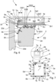
- Fig. 3 illustrates schematically a holding member 9 according to embodiments of the present disclosure.
- the holding member comprises a holding part 9a, a wall part 9c and a fixation part 9b.
- the holding member 9 may comprise, for example be made from, a metal or consist of metal such as steel, brass or aluminium.
- the holding member may comprise, for example be made from or consist of, a polymer material such as a fibre-reinforced polymer.
- the holding part 9a, wall part 9c, and fixation part 9b are integrated in a unitary body of the holding member 9.
- the holding part 9a of the holding member 9 is configured to extend into the space 10 (see fig. 2 ), and the fixation part 9b is configured to fixate the holding member, and hence the insulating glass unit 3, to a profile of a frame arrangement 2, 20. See e.g. fig. 4 .
- the fixation part 9b may in some embodiments of the present disclosure comprise fastening member engagement means 9d.
- the fastening member engagement means 9d comprises one or more holes 9d for receiving a fastening member 11a of mechanical fastening means 11.
- the fastening member engagement means 9d may comprise a slit, rim, recess and/or the like (not illustrated).
- the mechanical fastening means 11 may in embodiments of the present disclosure e.g. comprise one or more nails, screws, pop rivets, bolts and/or the like. In some embodiments, the mechanical fastening means may comprise one or more clips.
- Fig. 3 also illustrates a holding bracket 19 according to further embodiments of the present disclosure.
- the holding bracket 19 comprises a clamped part/part to be clamped 19a.
- This part 19a is configured to be clamped between the holding part 9a and the side portion 8, and thereby subjects a holding force as described in more details below.
- the clamped part 19a may comprises or consists of a resilient material and/or a polymer material that is softer than the material of the holding part 9a.
- the clamped part/part to be clamped 19a may be made from or comprise the same material as the holding part 9a.
- the holding bracket 19 may comprise or consist of a polymer, such as a plastic material, such as a fibre reinforced polymer.
- the holding bracket 19 comprises a recessed portion 19b for receiving the holding part.
- the recessed portion 19b may be provided as a hole, either a hole with a bottom or a bottomless hole (i.e. a through hole) a slit, or the like.
- the recessed portion 19b may be provided between wall parts 19a, 19c, where one of the wall parts may comprise the clamped part/part to be clamped 19a.
- the holding bracket 19 may (as illustrated in fig. 3 ) be a part that is separate to the holding member 9. In other embodiments of the present disclosure, the holding bracket may be integrated in or attached to the holding member 9, such as integrated in or attached to the holding part 9a.
- Fig. 4 illustrates schematically a cross sectional view of a roof window 1 according to embodiments of the present disclosure.
- the insulating glass unit 3 comprises the first and second glass sheets, and the insulating gap 4a placed there between.
- the insulating gap 4a is sealed by means of the edge seal 6 that may be arranged between the major surfaces 3a1 and 3b2 of the glass sheets 3a, 3b.
- the side portion 8 of the major surface 3b2 of the second glass sheet 3b extends with the distance DIS1 past the part 6e of the edge seal 6 that faces away from the insulating gap 4a, and thereby provides the space 10 opposite to the side portion 8 and where the space 10 is located opposite to said part 6e of the edge seal 6.
- the frame arrangement 2 supports the insulating glass unit 3 and the insulating glass unit 3 overlaps one or more of the frame profiles 2a-2d (see fig. 1 ) of the frame arrangement 2.
- the left elongated profile 2d is illustrated.
- the wall part 9c of the holding member 9 overlaps the side edge 7b of the second glass sheet 3b.
- the frame profile 2d comprises a first exterior side ES1 that faces the frame opening FO.
- the exterior side surface of the profile facing the frame opening FO provides the exterior side.
- the frame opening is provided between the profiles 2a-2d of the frame, and the profiles 2a-2d surrounds the frame opening, see fig. 1 .
- the frame profile 2d also comprises a second exterior side ES2 facing away from the frame opening FO.
- the second exterior side surface of the profile facing away from the frame opening FO provides the second exterior side ES2.
- the fixation part 9b overlaps the second exterior side ES2 of the overlapped frame profile 2d and is attached to the overlapped frame profile 2d at the second exterior side ES2 by means of the mechanical fastening means 11.
- the holding part 9a of the holding member 9 extends into the space 10 and provides a holding force towards the side portion 8 so as to secure the insulating glass unit 3 at the frame arrangement 2. It is generally understood that the holding force provided by the holding member 9 may be considered a clamping force that clamps the glass sheet 3b, and possibly also the lamination glass, if present, towards the overlapped frame profile 2a-2d and deforms a resilient gasket 12.
- the frame profiles 2a-2d, 20a-20d may be hollow (not illustrated in fig. 4 ) and comprise one or more interior spaces that are enclosed by walls of the profile. This/these spaces may be filled with a heat insulating material (not illustrated), and/or may comprise one or more air spaces for insulation purposes.
- the interior of the frame profiles may be massive, e.g. provided by a massive wood profile.
- the gasket 12 is placed between the interior major surface 3Li and a third external side ES3 of the profile 2d that faces and overlaps the insulating glass unit 3.
- the third external side ES3 is provided by the surface of the profile 2d that faces and overlaps the insulating glass unit 3.
- the gasket 12 is preferably resilient and is partly compressed between the insulating glass unit 3 and the overlapped profile 2d side surface ES3.
- the gasket may be made from a natural rubber or synthetic rubber material, a silicone material and/or the like. In some embodiments of the present disclosure, the gasket may overlap at least 25%, such as at least 33%, for example at least 50% of the maximum width MW1 of the profile 2d.
- the holding bracket 19 may be a loose, separate part.
- the holding bracket 19 may be an integrated part of the gasket 12, and the gasket 12 may thus comprise parts extending around the edge 7b to the portion 8 so as to provide at least the clamped part 19a that is clamped between the holding part 9a and the side portion 8 subjected to the holding force provided by the holding member 9 by means of the holding part 9a.
- both the clamped part19a, and the opposing wall part 19c (if present - it 19c may in some embodiments of the present disclosure be omitted) of the holding bracket 19 that is placed at the other side of the recessed portion 19b may be integrated in the gasket 12.
- the side portion 8 may as illustrated be placed opposite to the profile 2d.
- the edge 7b of the insulating glass unit glass sheet 3b may be placed opposite to the profile 2d and not extend out over the outermost exterior periphery of the profile that the second exterior side ES2.
- the second exterior surface ES2 may not be entirely plane, and may in some embodiments of the present disclosure comprise a contact surface ES2S, such as a plane surface.
- the contact surface ES2S faces away from the frame opening FO but may be arranged with an acute angle a1 relative to the interior major surface 3Li of the insulated glass unit 3.
- the angle a1 may be between 10° and 80°, such as between 20° and 75°.
- This part of the surface ES2S of the second exterior side ES2 faces towards a plane PL1 defined by/comprising the interior major surface 3Li of the insulating glass unit.
- the mechanical fastening means 11 comprises a fastening member 11a, such as an elongated fastening member, for engaging with the overlapped frame profile 2d at the contact surface part ES2S of the exterior side surface ES2.
- the fastening member 11a extends in an insertion direction IDIR.
- the insertion direction ISDR extends with an acute angle a2 relative to the plane PL1 of the interior major surface 3Li of the insulating glass unit 3 facing the frame opening.
- the insertion direction is in a direction away from the plane PL1.
- the insertion direction IDIR may preferably be within ⁇ 35°, such as within ⁇ 20°, for example within ⁇ 10° from a direction that is perpendicular to the contact surface ES2S.
- another part of the second exterior surface ES2 may extend with another angle to the plane PL1 than the contact surface ES2S of the second exterior surface ES2, for example substantially perpendicular to the plane PL1.
- the contact surface ES2S may extend substantially perpendicular to the plane PL1, and hence, the insertion direction IDIR may be substantially parallel to the plane PL1 or within ⁇ 35°, such as within ⁇ 20°, for example within ⁇ 10° from a direction that is parallel to the plane PL1.
- the fixation part 9b may extend in a direction that may be perpendicular to the plane PL1.
- the mechanical fastening means 11 comprises manipulation means 11b, such as a screw head, for operating the mechanical fastening means 11.
- manipulation means 11b such as a screw head
- the interior major surface 3Li of the insulating glass unit glass sheet 3b extends over a part ES2S of the surface ES2, so that the interior major surface 3Li of the insulating glass unit overlaps the fastening member manipulation means 11b.
- the insulating gap 4a overlaps the frame profile 2d with an overlapping distance DIS2.
- the insulating gap 4a may as illustrated in fig. 4 overlap the profile surface ES3.
- the insulating gap 4a may overlap at least 25% of the maximum width MW1 of the profile 2d, such as at least 33%, for example at least 50% or at least 65% of the maximum width MW1 of the profile 2d.
- the overlapped profile 2d is in fig. 4 a side profile 2d of a movable frame 2.
- the side profile extends between top and bottom frame profiles 2a, 2b of the movable frame 2 (see fig. 1 ).
- the movable frame 2 is configured to rotate around an axis of rotation RAX that is perpendicular to a longitudinal direction of the overlapped side profile 2d.
- the overlapped profile may additionally or alternatively comprise the other side profile 2c, the top profile 2a and/or the bottom profile 2b.
- the holding member 9 may as illustrated in fig. 4 be configured so that all parts 9a, 9b, 9c of the holding member 9 is located at the same side of a plane PL2 defined by a major surface 3a1, 3a2 of the first glass sheet 3a.
- said plane PL2 may be defined by an exterior major surface 3a2 of the first glass sheet 3a that faces away from the gap 4a.
- Fig. 5 illustrates schematically an embodiment of the present disclosure where the side portion 8 is terminated at the edge 7b of the second glass sheet 3b, and the first glass sheet 3a extend beyond said edge 7b of the second glass sheet 3b.
- the first glass sheet 3a may overlap a frame profile 20b of a fixation frame 20 of the roof window not illustrated in fig. 5 . This may additionally or alternatively help to hide the holding member(s) 9.
- Fig. 6 illustrates an embodiment of the present disclosure, where the roof window 1 is a centre hung type window.
- the fixation frame 20 (in the present example fixation frame profile 20d is illustrated) surrounds the movable frame 2 and the fixation frame profile 20d is thus placed opposite to the exterior side ES2 of the movable frame 2, at least when the movable frame is in a closed position as illustrated.
- the fixation frame hence hides a part of the holding member 9a.
- the fixation frame 20 may be placed opposite to both the holding part 9a, wall part 9c and fixation part 9b when the movable frame is in a closed position.
- Fig. 7 illustrates schematically an insulating glass unit according to embodiments of the present disclosure.
- the insulating glass unit 3 may comprise a plurality of said space 10 located opposite different side portions and opposite to the part 6e of different edge seal 6 parts enclosing the gap 4a. These plurality of spaces 10 are arranged along different sides Sa-Sd of the rectangular insulating glass unit 3.
- the insulating glass unit 3 is attached to the frame arrangement 2 (not illustrated in fig. 7 ) by means of a plurality of said holding members 9, and the holding members 9 are discretely arranged along the different sides of the insulating glass unit 3.
- the holding members 9 at the bottom may be fully overlapped by the first glass sheet 3a at the bottom Sb, whereas for example at the sides Sc and Sd and/or the top Sa, where some of the holding member may not be overlapped by the glass first sheet 3 a.
- one, two, three, four or even more holding members 9 may be arranged/distributed at each of one, two three or all sides Sa-Sd of the insulating glass unit 3.
- two holding members 9 are arranged/distributed at each of the four sides Sa-Sd of the insulating glass unit 3.
Landscapes
- Engineering & Computer Science (AREA)
- Civil Engineering (AREA)
- Structural Engineering (AREA)
- Architecture (AREA)
- Securing Of Glass Panes Or The Like (AREA)
Abstract
Description
- The present disclosure relates to a roof window for installation in a roof structure of a building.
- Generally, roof windows for installation in a roof structure of a building are popular, since such roof windows may provide e.g. increased/desired inflow of natural light/sunlight, help to provide heating, provide ventilation options and/or the like. However, such roof windows may require a more complex window design in order to for example assure sufficient water tightening. Also, it is a desire to provide aesthetically advantageous roof window solutions that are also user friendly to install and/or maintain.
- Patent document
US 5 355 644 discloses a roof window comprising a glass unit, a sash member, a glass retaining member and gaskets. This solution may e.g. suffer from aesthetic disadvantages.Patent document EP 3 677 734 discloses another solution where a holding part extends in between glass sheets of an insulating glass unit. This solution may suffer from drawbacks with regard to functionalities of the window, heat insulation performance and/or aesthetic disadvantages. - The present disclosure provides a solution that may solve one or more of the above mentioned drawbacks and e.g. provide an aesthetically desirable, energy efficient and yet user friendly solution.
- The present disclosure relates to a roof window for installation in a roof structure of a building. The roof window comprises a frame arrangement comprising structural elongated frame profiles that encloses a frame opening. The frame profiles each comprises a first exterior side facing the frame opening and a second exterior side facing away from the frame opening. The roof window also comprises one or more holding members comprising a holding part, a wall part, and a fixation part. Moreover, the roof window comprises an insulating glass unit comprising at least a first glass sheet and a second glass sheet. An insulating gap is provided between a major surface of the first glass sheet which faces the insulating gap and a major surface of the second glass sheet which faces the insulating gap. The insulating gap is sealed by means of an edge seal arranged between said major surface of the first glass sheet and said major surface of the second glass sheet. A side portion of the major surface of the second glass sheet extends with a distance past a part of the edge seal that faces away from the insulating gap so as to provide a space opposite to said side portion and where the space is located opposite to said part of the edge seal. The frame arrangement supports the insulating glass unit and the insulating glass unit overlaps one or more of the frame profiles. The wall part overlaps a side edge of the second glass sheet. The fixation part overlaps the second exterior side of the overlapped frame profile and is attached to the overlapped frame profile at the second exterior side. The holding part extends into the space and provides a holding force towards the side portion so as to secure the insulating glass unit at the frame arrangement.
- The present disclosure provides a solution where aesthetical advantages are obtainable as the outer surface of the first glass sheet that faces away from the insulating gap may hence be un-overlapped by the holding member while still providing a good fixation of the frame arrangement.
- The solution provides a reliable assembly of roof windows with glazing units which are exposed to more heat and thermal expansion/creep and also need to be watertight.
- Additionally or alternatively, the solution may help to provide a simplified frame design that may user friendly. As the fixation part overlaps the second exterior side and is attached to the overlapped frame profile at the second exterior side, more easy access to the fixation part may be provided. This enables a user friendly solution when for example the insulating glass unit should be replaced and/or during manufacturing of the roof window. Additionally or alternatively, the fact that the fixation part is attached to the overlapped frame profile at the second exterior side may enable a mechanically simple, yet user friendly and aesthetically advantageous solution for glass unit fixation and replacement.
- The present disclosure may also provide advantages in relation to obtaining a mechanically simple, yet user friendly, solution for enabling adjusting/adapting the holding force at the side portion.
- Side part(s) of the insulating glass unit that comprises the elongated space may hence overlap the frame profile in the width direction of the frame profile, and the outermost part of the side part(s) of the insulating glass unit that overlaps the frame profile comprises the elongated space that receives the holding part.
- A resilient gasket is preferably placed sandwiched between the interior major surface of the insulating glass unit and surface of the overlapped frame member that faces towards the interior major surface of the insulating glass unit, and this gasket may in preferred embodiments of the present disclosure be compressed due to the holding force.
- In one or more embodiments of the present disclosure, a side portion of a major surface of the first glass sheet may extend with a distance past the outer side surface of the first edge seal that faces away from the first insulating gap, wherein said side portion of the major surface of the first glass sheet is placed opposite to the side portion of the major surface of the second glass sheet, and wherein said elongated space is placed between said side portions.
- This may help to provide an improved "glass to edge" design at the exterior side of the roof window, and also help to hide the holding part.
- In one or more embodiments of the present disclosure, the said part of the edge seal that faces away from the insulating gap may be an outer side surface of the edge seal.
- In one or more embodiments of the present disclosure, the fixation part is attached to the overlapped frame profile at the second exterior side by means of mechanical fastening means.
- Such mechanical fastening means may e.g. help to enable advantageous replacement of the insulating glass unit.
- In further embodiments of the present disclosure, said mechanical fastening means may comprise one or more screws, clips and/or pop rivets.
- In one or more embodiments of the present disclosure, the mechanical fastening means may comprise a fastening member, such as an elongated fastening member, for engaging with the overlapped frame profile. The fastening member may here extend in an insertion direction, and the insertion direction may extend with an acute angle relative to a plane defined by the interior major surface of the insulating glass unit facing the frame opening, in a direction away from the plane. In further embodiments of the present disclosure, the direction may be towards a surface part of the second exterior side.
- This may help to enable advantageous adjustment of the holding force. The insertion direction is (partly) in a direction away from a plane defined by the interior major surface and in a direction away from the insulating glass unit. This may e.g. enable providing a gradual increase or decrease in the holding force dependent on how much the fastening means are "tightened" or displaced.
- The fastening member is preferably, in embodiments of the present disclosure, placed opposite to the interior major surface of the insulating glass unit.
- The insertion direction may also allow better access to the fastening member to allow subsequent replacement of the insulated glass unit - after the roof window is installed into the roof construction where tool access may be limited. This may for example, in some situations, be relevant if the roof window is of the type where the insulated/insulating glass unit is unmovable attached to a fixation frame not comprising a movable frame.
- However if burglar resistance is a concern then the access to the fastening member may be covered - for example by a frame part.
- Another advantage of the insertion direction when/if the fastener is a screw may be that it may provide a higher strength when screwed diagonally into the frame.
- In one or more embodiments of the present disclosure, the mechanical fastening means may comprise manipulation means for operating the mechanical fastening means, wherein the interior major surface of the insulating glass unit overlaps the fastening member manipulation means.
- This provides that the mechanical fastening means, and preferably also the fixation part is/are hidden underneath the insulting glass unit, and this may e.g. provide aesthetical advantages and/or advantages in relation to burglary protection.
- It may generally be preferred that the insulating glass unit, such as the interior major surface of the insulating glass unit overlaps the entire fastening part so that the fastening part do not extend beyond the edge of the first and/or second glass sheet.
- In embodiments, the interior major surface of the insulating glass unit preferably also overlaps the manipulation means.
- In some embodiments of the present disclosure, the manipulation means may comprise or be a screw head. The manipulation means may in embodiments of the present disclosure be configured to be manipulated by means of a tool (such as a hand held screw driver, a battery driven screw driver, hammer or the like), or by hand.
- In one or more embodiments of the present disclosure, a contact surface, such as a plane contact surface, of the second exterior side may face towards, such as abut, a contact surface of the fixation part. The contact surface of the second exterior side may be arranged with an acute angle relative to the interior major surface of the insulated glass unit so that the contact surface of the second exterior side faces towards a plane defined by the interior major surface of the insulating glass unit.
- This may enable an advantageous adaption of the pressure force applied at the insulating glass unit. Gaskets between the insulating glass unit and the overlapped profile may change characteristics over time, and adaption of the pressure provided by the insulating glass units onto such gaskets may be advantageous to adjust to adapt to the specific conditions at the window.
- When making the mechanical fastening means engage with the profile, a pulling force may be provided by the fixation part in a direction away from the interior major surface of the insulating glass unit. This provides that the holding part provides the holding force onto the said side portion so that the insulating glass unit is pulled towards the overlapped frame member.
- In one or more embodiments of the present disclosure, the fixation part, such as a plate shaped fixation part, is arranged with an acute angle relative to a plane defined by an the interior major surface of the insulated glass unit so that a contact surface of the fixation part faces away from said plane and extends along, such as abuts, the contact surface of the second exterior side of the frame profile.
- In one or more embodiments of the present disclosure, the holding part, wall part (9c), and fixation part may be integrated in a unitary body of the holding member.
- This provides a mechanical simple, strong and cost efficient holding solution.
- The wall part preferably interconnects the holding part and fixation part.
- In one or more embodiments of the present disclosure, the holding member comprises metal or consist of metal such as steel, brass or aluminium.
- Metal provides good strength and is long lasting. However, metal such as steel, brass or aluminium has a high thermal conductivity coefficient. Since the holding member is attached at the second exterior side facing away from the frame opening, it may hence not need extend in between, or at least not extend a larger distance in between, the insulating glass unit and the overlapped frame member. Hence, cold bridges in between e.g. the insulating glass unit and the overlapped frame profile due to the holding member may be omitted or reduced, and hence, heat insulation performance may be improved and/or condensation issues may be reduced while improving aesthetics and/or user friendliness.
- In one or more embodiments of the present disclosure, the insulating gap may overlap the frame profile with an overlapping distance.
- This provides enhanced heat insulation performance. Also it may help to enable a more space saving holding member and/or enable providing an improved "glass to frame edge" impression from the exterior of the roof window. Additionally or alternatively, it may e.g. provide the advantage of enhanced heat insulation due to increased insulated glazing unit area.
- In one or more embodiments of the present disclosure, a lamination glass sheet may be attached to a major surface of the second glass sheet by means of a lamination interlayer. In further embodiments, the lamination glass sheet may provide the interior major surface of the insulating glass unit for facing the interior of the building.
- This provides improved safety. The holding part may hence clamp/press the second glass sheet and the lamination glass sheet towards the overlapped surface of the frame profile, and press a part of the interior major surface of the insulating glass unit (e.g. provided by a major surface of the lamination glass sheet) towards a gasket.
- In one or more embodiments of the present disclosure, the holding part may engage a holding bracket. The holding bracket may comprise a clamped part that is clamped between the holding part and the side portion subjected to the holding force.
- In embodiments of the present disclosure, at least the clamped part may comprise or consists of a material that is softer than the material of the holding part. In embodiments of the present disclosure, at least the clamped part may comprise or consists of a resilient material that is softer than the material of the holding part. In embodiments of the present disclosure, at least the clamped part may comprise or consists of a polymer material that is softer than the material of the holding part.
- This may help to provide a more gentle fixation of the insulating glass unit, thereby reducing the risk of glass unit damage over time. It may also help to enable providing a holding member of a harder/stronger material, such as a metal. Additionally or alternatively, this may be advantageous in order to reduce heat transfer between the holding member and the glass sheet comprising the side portion of the major surface of the second glass sheet.
- In one or more embodiments of the present disclosure, said elongated frame profiles may be frame profiles of a movable frame, and the movable frame may be attached to a fixation frame of the roof window by means of a hinge arrangement. In further embodiments of the present disclosure, the roof window may be of the centre-hung type.
- In some embodiments where the roof window is of the centre-hung type, such roof windows may be configured so that the movable frame can be rotated to an open position where the exterior major surface of the first glass sheet faces inwards towards the building, thereby providing advantageous cleaning options. Such windows are exposed to changing gravity direction and exposed to slams and require reliable glass fixation.
- In some embodiments where the roof window is of the centre-hung type, the fixation frame may overlap and hide the fixation part of the holding member when the movable frame is in a closed position.
- In some embodiments where the roof window is of the centre-hung type, the fixation frame may surround the movable frame.
- In one or more embodiments of the present disclosure, the overlapped, elongated frame profile may be a side profile of a movable frame, wherein said side profile extends between top and bottom frame profiles of the movable frame. In further embodiments, the movable frame may be configured to rotate around an axis of rotation that is perpendicular to a longitudinal direction of the overlapped side profile.
- In one or more embodiments of the present disclosure, the overlapped frame profile may be a bottom profile of the frame arrangement.
- In one or more embodiments of the present disclosure, the holding member may be configured so that all parts of the holding member is located at the same side of a plane defined by a major surface of the first glass sheet. In further embodiments of the present disclosure said plane may be defined by an exterior major surface of the first glass sheet that faces away from the gap.
- Hence the exterior major surface of the insulating glass unit is un-overlapped by the holding member, and this may provide aesthetic advantages.
- In one or more embodiments of the present disclosure, the said side portion may be terminated at an edge of the second glass sheet, and the first glass sheet may extend beyond said edge of the second glass sheet. In further embodiments of the present disclosure, this may be provided so as to overlap a frame profile of a fixation frame of the roof window.
- In one or more embodiments of the present disclosure, the insulating glass unit may comprise a plurality of said space located opposite different side portion and opposite to the part of different edge seal parts enclosing the gap. The plurality of spaces may be arranged along different sides of the insulating glass unit, and the insulating glass unit may be attached to the frame arrangement by means of a plurality of said holding members that are discretely arranged along said different sides of the insulating glass unit.
- In further embodiments, said holding members may be arranged at opposing sides of the insulating glass unit so that holding parts of the holding members provides a holding force towards the side portion to secure the insulating glass unit at the frame arrangement at different frame profiles of the frame arrangement.
- Aspects of the present disclosure will be described in the following with reference to the figures in which:
- fig. 1
- : illustrates a roof window according to embodiments of the present disclosure,
- fig. 2
- : illustrates a side part of an insulated glass unit according to embodiments of the present disclosure,
- fig. 3
- : illustrates a holding member according to embodiments of the present disclosure,
- fig. 4
- : illustrates a roof window comprising a holding member according to embodiments of the present disclosure
- fig. 5
- : illustrates a side part of an insulated glass unit according to further embodiments of the present disclosure,
- fig. 6
- : illustrates a
roof window 1 of the centre hung type comprising a movable frame and a fixation frame, and - Fig. 7
- : illustrates an insulating glass unit and discretely arranged holding members according to embodiments of the present disclosure.
-
Fig. 1 illustrates schematically aroof window 1 according to embodiments of the present disclosure. Theroof window 1 may also be known as a skylight. Theroof window 1 comprises aframe arrangement fixation frame 20 and amovable frame 2. Themovable frame 2 provides a support of an insulatingglass unit 3. - The
movable frame 2 is movably attached to thefixation frame 20 by means of ahinge arrangement 30. Infig. 1 , theroof window 1 is of the centre-hung type. In centre-hungtype roof windows 1, thehinge arrangement 30 provides an axis of rotation RAX for themovable frame 2 that is placed between the top T and the bottom B of the sash/movable frame 2. This provides that themovable frame 2 is configured to be opened by the lower part/bottom part B of the movable frame moving outwards, away from the interior of the building in which theroof window 1 is installed, and the upper part/top part T of themovable frame 2 moves inwards into the building upon opening of themovable frame 2 from a closed position. It is understood that the axis of rotation RAX may be arranged around the centre of the lengths of theside profiles movable frame 1. This is also understood as a centre hung roof window according to the present disclosure. Centre-hung windows may also be referred to pivot roof windows. - In roof windows of the centre-hung type, the
fixation frame 20 may surroundmovable frame 2. Inroof windows 1 of the centre-hung type, the maximum width of themovable frame 2 may be less than the interior, minimum width of the frame opening of thefixation frame 20 in order to allow top T and bottom B parts of themovable frame 2 to move into the frame opening of thefixation frame 20 when moving themovable frame 2 to a closed position. - In other embodiments of the present disclosure, the
movable frame 2 may be hinged in another way, for example top hung (not illustrated). In still further embodiments, the roof window may be of the type where the insulated/insulatingglass unit 3 is unmovable attached to a fixation frame. - The
fixation frame 20 comprisesparallel side profiles top profile 20a and abottom profile 20b placed parallel to the top profile. Theseprofiles 20a-20d are elongated and together they provides a rectangularfixation frame opening 21. - The
movable frame 2 comprises elongated frame profiles comprising atop profile 2a, and abottom profile 2b. These, 2a, 2b, are placed parallel to each other. Themovable frame 2 also comprises parallel side profiles 2c, 2d. Theseprofiles 2a-2d are elongated and together they provide a rectangular frame opening in themovable frame 2, and light passes through this frame opening. Themovable frame 2 supports an insulated glass unit. The insulated glass unit is fixated to themovable frame 2, and covers the frame opening of themovable frame 2 that is placed between theprofiles 2a-2d of the movable frame. - The
roof window 1 also comprisescovers type 1 may comprise fixedcovers 9a that is fixed to the fixation frame, preferably proximate the top TF of thefixation frame 20. Moreover, the window comprisesmovable covers 9b that are fixed to themovable frame 2 and moves together with themovable frame 2. Thesemovable covers 9b are often placed proximate the lower part/bottom part B of themovable frame 2. The width of thecovers fixation frame 20 and also the movable frame 2 (see e.g.fig. 3 ) in order to improve water tightening. When the movable frame is in a closed position, the fixed covers 9a and themovable covers 9b may be placed in continuation of each other. Thecovers roof window 1, between the top and bottom of theroof window 1. Thecovers 20 9a, 9b are exterior covers that are subjected to the weather - The
roof window 1 may also comprise atop cover 9c that is arranged at the top TF of thefixation frame 20. Thistop cover 9c also overlaps the top T of the movable frame when themovable frame 2 is placed in a closed position. Infig. 1 , themovable frame 2 is in an open position. -
Fig. 2 illustrates schematically a cross sectional view of a side part of aninsulated glass unit 3 according to embodiments of the present disclosure, for installation in a roof window 1 (not illustrated infig. 1 ) according to embodiments of the present disclosure. Theinsulated glass unit 3 offig. 2 comprises a first,outer glass sheet 3a, and asecond glass sheet 3b. Theglass sheets - Generally, the
first glass sheet 3a may be configured to face the exterior EXT of the building (seefig. 3 ) when theroof window 1 is installed in a roof structure of the building and theinsulated glass unit 3 is fixed to a fixed frame, or fixed to amovable frame 2 as infig. 1 (when themovable frame 2 is in a closed position). - An insulating
gap 4a is provided between an inner, major surface 3a1 of the first,outer glass sheet 3a, and a major surface 3b2 of thesecond glass sheet 3b, these surfaces 3a1, 3b2 faces each other. The insulatinggap 4a is sealed by means of anedge seal 6. - The major surface 3b2 of the
second glass sheet 3b may as illustrated face and preferably abut the insulatinggap 4a. The major surface 3a1 of the first, outer glass sheet may as illustrated face and preferably abut the first insulatinggap 4a. - The edge seal(s) 6 of the insulated
glass unit 3 may in embodiments of the present disclosure comprise spacer bars. Such spacer bars, that may be common, comprises a metal profile, a composite profile, a structural foam or TPS (thermoplastic) and/or the like. Other spacer bars may be used. Spacer bar may in some embodiments comprise a desiccant for absorbing moisture. Theedge seal 6 functions as a gas barrier sealant to keep an insulating gas (commonly argon) in the insulatinggap 4a for the lifetime of the insulated glass unit. The edge seal(s) 6 may also structurally hold theglass panes 3a-3c joined as a single, insulatingglass unit 3. - As can be seen, the
side surfaces edge seal 6 are opposing and faces in opposite directions, and extends between the glass sheet surfaces 3a1, 3b2. Thesurface 6e faces away from the insulatinggap 4a whereas thesurface 6i faces the insulatinggap 4a, and the interior of the edge seal may be solid, hollow (partly or fully) and/or filled with a desired material such as an heat insulation material and/or desiccant for absorbing moisture. - One or more of the
glass sheets - In
fig. 2 , the insulatingglass unit 3 is a laminated glass unit, and hence, a furtherlamination glass sheet 3L is attached to thesecond glass sheet 3b surface 3b1 by means of a lamination layer LL, such as an adhesive. The lamination layer LL may for example comprise EVA (Ethylene Vinyl Acetate) or PVB (Polyvinyl butyral) and should be transparent to visible light so that sunlight can pass through the insulated glass unit. The lamination of the insulated glass unit provides safety, and may e.g. be advantageous in roof windows. Although theglass sheet 3b may be considered the inner glass sheet of the insulated/insulatingglass unit 3, thelamination glass sheet 3L is often arranged as the innermost glass sheet of the window (when the movable frame, if present, is in a closed position), and may provide the major surface 3Li for facing, such as abutting, the interior of the building. This surface 3Li is placed opposite to the surface of theglass sheet 3L that is attached to the glass sheet 3c by means of the lamination lay LL. - The
first glass sheet 3a comprises the major surface 3a2 that faces away from the first insulatinggap 4a. This surface 3a2 may in some embodiments of the present disclosure be the major outer surface configured to face the exterior of the building (seefig. 3 ) when the movable frame 2 (seefig 1 ) is in a closed position, and may hence be subjected to weather such as rain, snow, hail and/or the like. - The
major surface 3bglass sheet 3b or the major surface of thelamination glass 3L may face the interior INT of the building (see e.g.fig. 4 ). - According to preferred embodiments of the present disclosure, a
side portion 8 of the major surface 3b2 of thesecond glass sheet 3b extends with a distance DIS1 past apart 6e of theedge seal 6 that faces away from the insulatinggap 4a so as to provide aspace 10 opposite to saidside portion 8. Thespace 10 is located opposite to thepart 6e of theedge seal 6. - In the example of
fig. 2 , the part of theedge seal 6e that faces away from the insulatinggap 4a so as to provide thespace 10 may be anouter side surface 6e, such as an outer side surface of theedge seal 6. Theedge seal 6 also comprises aninterior side surface 6i that faces towards and abuts thegap 4a. Infig. 2 , - This solution provides an
elongated space 10 which overlaps theside portion 8 and is placed next to theedge seal 6. - As can be seen in
fig. 2 a side portion 5 of a major surface 3a1 of thefirst glass sheet 3a may in further embodiments of the present disclosure extend with a distance past a part, such as theouter side surface 6e of theedge seal 6 that faces away from the first insulatinggap 4a. At least a part of the side portion 5 of the major surface 3a1 of thefirst glass sheet 3a is thus here placed opposite to theside portion 8 of the major surface 3b2 of thesecond glass sheet 3b, and theelongated space 10 is accordingly placed/located between saidside portions 5, 8 of the major surfaces 3a1, 3b2. - It is generally understood that one or more of the major surfaces 3a1, 3a2, 3b1, 3b2 may be coated with various layers to provide features such as reflection and/or filtering, or other features. For example such coatings may comprise so called low-e coatings. Such coatings may be considered part of the respective glass sheet and hence provide the one or more of the major surfaces 3a1, 3a2, 3b1, 3b2. Such coatings may naturally also be omitted at one or more of said major surfaces.
-
Fig. 3 illustrates schematically a holdingmember 9 according to embodiments of the present disclosure. The holding member comprises a holdingpart 9a, awall part 9c and afixation part 9b. In one or more embodiments of the present disclosure, the holdingmember 9 may comprise, for example be made from, a metal or consist of metal such as steel, brass or aluminium. In other embodiments, the holding member may comprise, for example be made from or consist of, a polymer material such as a fibre-reinforced polymer. - The holding
part 9a,wall part 9c, andfixation part 9b are integrated in a unitary body of the holdingmember 9. - The holding
part 9a of the holdingmember 9 is configured to extend into the space 10 (seefig. 2 ), and thefixation part 9b is configured to fixate the holding member, and hence the insulatingglass unit 3, to a profile of aframe arrangement fig. 4 . - The
fixation part 9b may in some embodiments of the present disclosure comprise fastening member engagement means 9d. In the present example, the fastening member engagement means 9d comprises one ormore holes 9d for receiving afastening member 11a of mechanical fastening means 11. In other embodiments of the present disclosure, the fastening member engagement means 9d may comprise a slit, rim, recess and/or the like (not illustrated). - The mechanical fastening means 11 may in embodiments of the present disclosure e.g. comprise one or more nails, screws, pop rivets, bolts and/or the like. In some embodiments, the mechanical fastening means may comprise one or more clips.
-
Fig. 3 also illustrates a holdingbracket 19 according to further embodiments of the present disclosure. The holdingbracket 19 comprises a clamped part/part to be clamped 19a. Thispart 19a is configured to be clamped between the holdingpart 9a and theside portion 8, and thereby subjects a holding force as described in more details below. In some embodiments of the present disclosure, the clampedpart 19a may comprises or consists of a resilient material and/or a polymer material that is softer than the material of the holdingpart 9a. In other embodiments, the clamped part/part to be clamped 19a may be made from or comprise the same material as the holdingpart 9a. The holdingbracket 19 may comprise or consist of a polymer, such as a plastic material, such as a fibre reinforced polymer. - The holding
bracket 19 comprises a recessedportion 19b for receiving the holding part. In some embodiments, the recessedportion 19b may be provided as a hole, either a hole with a bottom or a bottomless hole (i.e. a through hole) a slit, or the like. Hence, the recessedportion 19b may be provided betweenwall parts - The present disclosure, the holding
bracket 19 may (as illustrated infig. 3 ) be a part that is separate to the holdingmember 9. In other embodiments of the present disclosure, the holding bracket may be integrated in or attached to the holdingmember 9, such as integrated in or attached to the holdingpart 9a. -
Fig. 4 illustrates schematically a cross sectional view of aroof window 1 according to embodiments of the present disclosure. - As previously mentioned, the insulating
glass unit 3 comprises the first and second glass sheets, and the insulatinggap 4a placed there between. The insulatinggap 4a is sealed by means of theedge seal 6 that may be arranged between the major surfaces 3a1 and 3b2 of theglass sheets side portion 8 of the major surface 3b2 of thesecond glass sheet 3b extends with the distance DIS1 past thepart 6e of theedge seal 6 that faces away from the insulatinggap 4a, and thereby provides thespace 10 opposite to theside portion 8 and where thespace 10 is located opposite to saidpart 6e of theedge seal 6. - The
frame arrangement 2 supports the insulatingglass unit 3 and the insulatingglass unit 3 overlaps one or more of the frame profiles 2a-2d (seefig. 1 ) of theframe arrangement 2. In the present example, the leftelongated profile 2d is illustrated. - The
wall part 9c of the holdingmember 9 overlaps theside edge 7b of thesecond glass sheet 3b. - The
frame profile 2d comprises a first exterior side ES1 that faces the frame opening FO. The exterior side surface of the profile facing the frame opening FO provides the exterior side. The frame opening is provided between theprofiles 2a-2d of the frame, and theprofiles 2a-2d surrounds the frame opening, seefig. 1 . Theframe profile 2d also comprises a second exterior side ES2 facing away from the frame opening FO. The second exterior side surface of the profile facing away from the frame opening FO provides the second exterior side ES2. - The
fixation part 9b overlaps the second exterior side ES2 of the overlappedframe profile 2d and is attached to the overlappedframe profile 2d at the second exterior side ES2 by means of the mechanical fastening means 11. - The holding
part 9a of the holdingmember 9 extends into thespace 10 and provides a holding force towards theside portion 8 so as to secure the insulatingglass unit 3 at theframe arrangement 2. It is generally understood that the holding force provided by the holdingmember 9 may be considered a clamping force that clamps theglass sheet 3b, and possibly also the lamination glass, if present, towards the overlappedframe profile 2a-2d and deforms aresilient gasket 12. - It is generally understood that the frame profiles 2a-2d, 20a-20d (see
fig. 1 ) may be hollow (not illustrated infig. 4 ) and comprise one or more interior spaces that are enclosed by walls of the profile. This/these spaces may be filled with a heat insulating material (not illustrated), and/or may comprise one or more air spaces for insulation purposes. In further embodiments, the interior of the frame profiles may be massive, e.g. provided by a massive wood profile. - The
gasket 12 is placed between the interior major surface 3Li and a third external side ES3 of theprofile 2d that faces and overlaps the insulatingglass unit 3. The third external side ES3 is provided by the surface of theprofile 2d that faces and overlaps the insulatingglass unit 3. - The
gasket 12 is preferably resilient and is partly compressed between the insulatingglass unit 3 and the overlappedprofile 2d side surface ES3. The gasket may be made from a natural rubber or synthetic rubber material, a silicone material and/or the like. In some embodiments of the present disclosure, the gasket may overlap at least 25%, such as at least 33%, for example at least 50% of the maximum width MW1 of theprofile 2d. - It is generally understood that in some embodiments of the present disclosure, the holding
bracket 19 may be a loose, separate part. In other embodiments of the present disclosure (not illustrated), the holdingbracket 19 may be an integrated part of thegasket 12, and thegasket 12 may thus comprise parts extending around theedge 7b to theportion 8 so as to provide at least the clampedpart 19a that is clamped between the holdingpart 9a and theside portion 8 subjected to the holding force provided by the holdingmember 9 by means of the holdingpart 9a. In some further embodiments, both the clamped part19a, and the opposingwall part 19c (if present - it 19c may in some embodiments of the present disclosure be omitted) of the holdingbracket 19 that is placed at the other side of the recessedportion 19b may be integrated in thegasket 12. - In still further embodiments, the holding
bracket 19 may be attached to the holdingmember 9, such as attached to the holdingpart 9a, e.g. by mechanical and/or chemical fastening means. - In embodiments of the present disclosure, the
side portion 8 may as illustrated be placed opposite to theprofile 2d. In still further embodiments, theedge 7b of the insulating glassunit glass sheet 3b may be placed opposite to theprofile 2d and not extend out over the outermost exterior periphery of the profile that the second exterior side ES2. - As can be seen in
fig. 4 the second exterior surface ES2 may not be entirely plane, and may in some embodiments of the present disclosure comprise a contact surface ES2S, such as a plane surface. The contact surface ES2S faces away from the frame opening FO but may be arranged with an acute angle a1 relative to the interior major surface 3Li of the insulatedglass unit 3. The angle a1 may be between 10° and 80°, such as between 20° and 75°. This part of the surface ES2S of the second exterior side ES2 faces towards a plane PL1 defined by/comprising the interior major surface 3Li of the insulating glass unit. The surface ES2S acts as a contact surface for a contact surface 9CS of thefixation part 9b that faces the surface ES2S. The mechanical fastening means presses the surface 9CS towards the surface ES2S, thereby fixating the holding member to theprofile 9d. - The mechanical fastening means 11 comprises a
fastening member 11a, such as an elongated fastening member, for engaging with the overlappedframe profile 2d at the contact surface part ES2S of the exterior side surface ES2. Thefastening member 11a extends in an insertion direction IDIR. The insertion direction ISDR extends with an acute angle a2 relative to the plane PL1 of the interior major surface 3Li of the insulatingglass unit 3 facing the frame opening. The insertion direction is in a direction away from the plane PL1. The insertion direction IDIR may preferably be within ±35°, such as within ±20°, for example within ±10° from a direction that is perpendicular to the contact surface ES2S. As can be seen, another part of the second exterior surface ES2 may extend with another angle to the plane PL1 than the contact surface ES2S of the second exterior surface ES2, for example substantially perpendicular to the plane PL1. - In other embodiments of the present disclosure (not illustrated), the contact surface ES2S may extend substantially perpendicular to the plane PL1, and hence, the insertion direction IDIR may be substantially parallel to the plane PL1 or within ±35°, such as within ±20°, for example within ±10° from a direction that is parallel to the plane PL1. Hence, in this embodiment, the
fixation part 9b may extend in a direction that may be perpendicular to the plane PL1. - The mechanical fastening means 11 comprises manipulation means 11b, such as a screw head, for operating the mechanical fastening means 11. The interior major surface 3Li of the insulating glass
unit glass sheet 3b extends over a part ES2S of the surface ES2, so that the interior major surface 3Li of the insulating glass unit overlaps the fastening member manipulation means 11b. - As illustrated, the insulating
gap 4a overlaps theframe profile 2d with an overlapping distance DIS2. The insulatinggap 4a may as illustrated infig. 4 overlap the profile surface ES3. In some embodiments of the present disclosure, the insulatinggap 4a may overlap at least 25% of the maximum width MW1 of theprofile 2d, such as at least 33%, for example at least 50% or at least 65% of the maximum width MW1 of theprofile 2d. - The overlapped
profile 2d is infig. 4 aside profile 2d of amovable frame 2. The side profile extends between top andbottom frame profiles fig. 1 ). Preferably, themovable frame 2 is configured to rotate around an axis of rotation RAX that is perpendicular to a longitudinal direction of the overlappedside profile 2d. In other embodiments, the overlapped profile may additionally or alternatively comprise theother side profile 2c, thetop profile 2a and/or thebottom profile 2b. - The holding
member 9 may as illustrated infig. 4 be configured so that allparts member 9 is located at the same side of a plane PL2 defined by a major surface 3a1, 3a2 of thefirst glass sheet 3a. Preferably, said plane PL2 may be defined by an exterior major surface 3a2 of thefirst glass sheet 3a that faces away from thegap 4a. -
Fig. 5 illustrates schematically an embodiment of the present disclosure where theside portion 8 is terminated at theedge 7b of thesecond glass sheet 3b, and thefirst glass sheet 3a extend beyond saidedge 7b of thesecond glass sheet 3b. Thereby, thefirst glass sheet 3a may overlap aframe profile 20b of afixation frame 20 of the roof window not illustrated infig. 5 . This may additionally or alternatively help to hide the holding member(s) 9. -
Fig. 6 illustrates an embodiment of the present disclosure, where theroof window 1 is a centre hung type window. Here, the fixation frame 20 (in the present examplefixation frame profile 20d is illustrated) surrounds themovable frame 2 and thefixation frame profile 20d is thus placed opposite to the exterior side ES2 of themovable frame 2, at least when the movable frame is in a closed position as illustrated. The fixation frame hence hides a part of the holdingmember 9a. As illustrated, thefixation frame 20 may be placed opposite to both the holdingpart 9a,wall part 9c andfixation part 9b when the movable frame is in a closed position. -
Fig. 7 illustrates schematically an insulating glass unit according to embodiments of the present disclosure. It is generally understood that the insulatingglass unit 3 may comprise a plurality of saidspace 10 located opposite different side portions and opposite to thepart 6e ofdifferent edge seal 6 parts enclosing thegap 4a. These plurality ofspaces 10 are arranged along different sides Sa-Sd of the rectangular insulatingglass unit 3. The insulatingglass unit 3 is attached to the frame arrangement 2 (not illustrated infig. 7 ) by means of a plurality of said holdingmembers 9, and the holdingmembers 9 are discretely arranged along the different sides of the insulatingglass unit 3. - In
fig. 7 , the holdingmembers 9 are arranged at opposing sides Sa-Sd of the insulatingglass unit 3 so that holdingparts 9a of the holdingmembers 9 provides a holding force towards theside portion 8 to secure the insulatingglass unit 3 at theframe arrangement 2 at different frame profiles of the frame arrangement (not illustrated infig. 7 , see e.g.fig. 1 . As can be seen, the holdingbracket 19 is placed in thespace 10. - In
fig. 7 , the outer,first glass sheet 3a is larger than thesecond glass sheet 3b in length, while theglass sheets edge 7a overlap as illustrated infig. 2 , in this case at the bottom part of the insulating glass unit. Thereby, thefirst glass sheet 3a may overlap the fixation frame and move away from thebottom part 20b of the fixation frame and outwards when the movable frame is opened as for example illustratedfig. 1 . - Hence, the holding
members 9 at the bottom may be fully overlapped by thefirst glass sheet 3a at the bottom Sb, whereas for example at the sides Sc and Sd and/or the top Sa, where some of the holding member may not be overlapped by the glassfirst sheet 3 a. - In some embodiments of the present disclosure, one, two, three, four or even more holding
members 9 may be arranged/distributed at each of one, two three or all sides Sa-Sd of the insulatingglass unit 3. Infig. 7 , two holdingmembers 9 are arranged/distributed at each of the four sides Sa-Sd of the insulatingglass unit 3. - In general, it is to be understood that the present disclosure is not limited to the particular examples described above but may be adapted in a multitude of varieties within the scope of the invention as specified in e.g. the claims. Accordingly, for example, one or more of the described and/or illustrated embodiments above may be combined to provide further embodiments of the present disclosure.
Claims (15)
- A roof window (1) for installation in a roof structure of a building, wherein the roof window (1) comprises:- a frame arrangement (2) comprising structural elongated frame profiles (2a-2d) that encloses a frame opening (FO), wherein said frame profiles (2a-2d) each comprises a first exterior side (ES1) facing the frame opening (FO) and a second exterior side (ES2) facing away from the frame opening (FO),- one or more holding members (9) comprising a holding part (9a), a wall part (9c), and a fixation part (9b),- an insulating glass unit (3) comprising at least a first glass sheet (3a) and a second glass sheet (3b), wherein an insulating gap (4a) is provided between a major surface (3a1) of the first glass sheet (3a) which faces the insulating gap (4a) and a major surface (3b2) of the second glass sheet (3b) which faces the insulating gap (4a), where the insulating gap (4a) is sealed by means of an edge seal (6) arranged between said major surface (3a1) of the first glass sheet (3a) and said major surface (3b2) of the second glass sheet (3b),wherein a side portion (8) of the major surface (3b2) of the second glass sheet (3b) extends with a distance (DIS1) past a part (6e) of the edge seal (6) that faces away from the insulating gap (4a) so as to provide a space (10) opposite to said side portion (8) and where the space (10) is located opposite to said part (6e) of the edge seal (6),wherein the frame arrangement (2) supports the insulating glass unit (3) and wherein the insulating glass unit (3) overlaps one or more of the frame profiles (2a-2d), wherein the wall part (9c) overlaps a side edge (7b) of the second glass sheet (3b), and wherein the fixation part (9b) overlaps the second exterior side (ES2) of the overlapped frame profile (2a-2d) and is attached to the overlapped frame profile (2a-2d) at the second exterior side (ES2), andwherein the holding part (9a) extends (9) into the space (10) and provides a holding force towards the side portion (8) so as to secure the insulating glass unit (3) at the frame arrangement (2).
- A roof window (1) according to claim 1, wherein the fixation part (9b) is attached to the overlapped frame profile (2a-2d) at the second exterior side (ES2) by means of mechanical fastening means (11), preferably wherein said mechanical fastening means comprises one or more screws, clips and/or pop rivets.
- A roof window (1) according to claim 2, wherein the mechanical fastening means (11) comprises a fastening member (11a), such as an elongated fastening member, for engaging with the overlapped frame profile (2a-2d), wherein the fastening member (11a) extends in an insertion direction (IDIR), and wherein the insertion direction extends with an acute angle (a2) relative to a plane (PL1) defined by the interior major surface (3Li) of the insulating glass unit (3) facing the frame opening, in a direction away from the plane and towards a surface part (ES2S) of the second exterior side (ES2).
- A roof window (1) according to claim 2 or 3, wherein the mechanical fastening means (11) comprises manipulation means (11b), such as a screw head, for operating the mechanical fastening means (11), wherein the interior major surface (3Li) of the insulating glass unit overlaps the fastening member manipulation means (11b).
- A roof window (1) according to any of the preceding claims, wherein a contact surface (ES2S), such as a plane contact surface, of the second exterior side (ES2) faces towards, such as abuts, a contact surface (9CS) of the fixation part (9b), and wherein said contact surface (ES2S) of the second exterior side (ES2) is arranged with an acute angle (a1) relative to the interior major surface (3Li) of the insulated glass unit (3) so that the contact surface (ES2S) of the second exterior side (ES2) faces towards a plane (PL1) defined by the interior major surface (3Li) of the insulating glass unit.
- A roof window (1) according to any of the preceding claims, wherein the holding part (9a), wall part (9c), and fixation part (9b) are integrated in a unitary body of the holding member (9).
- A roof window (1) according to any of the preceding claims, wherein the holding member (9) comprises metal or consist of metal such as steel, brass or aluminium.
- A roof window (1) according to any of the preceding claims, wherein the insulating gap (4a) overlaps the frame profile (2a-2d) with an overlapping distance (DIS2).
- A roof window (1) according to any of the preceding claims, wherein a lamination glass sheet (3L) is attached to a major surface (3b1) of the second glass sheet (3b) by means of a lamination interlayer (LL), preferably wherein the lamination glass sheet (3L) provides the interior major surface (3Li) of the insulating glass unit (3) for facing the interior of the building.
- A roof window (1) according to any of the preceding claims, wherein the holding part (9a) engages a holding bracket (19), wherein the holding bracket (19) comprises a clamped part (19a) that is clamped between the holding part (9a) and the side portion (8) subjected to the holding force, preferably wherein at least the clamped part (19a) comprises or consists of a material, such as a resilient material and/or a polymer material, that is softer than the material of the holding part (9a).
- A roof window (1) according to any of the preceding claims, wherein said elongated frame profiles (2a-2d) are frame profiles of a movable frame (2), wherein the movable frame is attached to a fixation frame (20) by means of a hinge arrangement (30), such as wherein the roof window (1) is of the centre-hung type.
- A roof window (1) according to claim 11, wherein the overlapped, elongated frame profile is a side profile (2c, 2d) of a movable frame (2), wherein said side profile extends between top and bottom frame profiles (2a, 2b) of the movable frame (2), preferably wherein the movable frame (2) is configured to rotate around an axis of rotation (RAX) that is perpendicular to a longitudinal direction of the overlapped side profile (2c, 2d).
- A roof window (1) according to any of the preceding claims, wherein the holding member (9) is configured so that all parts (9a, 9b, 9c) of the holding member (9) is located at the same side of a plane (PL2) defined by a major surface (3a1, 3a2) of the first glass sheet (3a), preferably wherein said plane (PL2) is defined by an exterior major surface (3a2) of the first glass sheet (3a) that faces away from the gap (4a).
- A roof window (1) according to any of the preceding claims, wherein the side portion (8) is terminated at an edge (7b) of the second glass sheet (3b), and wherein the first glass sheet (3a) extend beyond said edge (7b) of the second glass sheet (3b), preferably so as to overlap a frame profile (20b) of a fixation frame (20) of the roof window.
- A roof window (1) according to any of the preceding claims, wherein the insulating glass unit (3) comprises a plurality of said space (10) located opposite different side portion (8) and opposite to the part (6e) of different edge seal (6) parts enclosing the gap (4a), wherein the plurality of spaces (10) are arranged along different sides (Sa-Sd) of the insulating glass unit (3),
wherein the insulating glass unit (3) is attached to the frame arrangement (2) by means of a plurality of said holding members (9), wherein the plurality of holding members (9) are discretely arranged along said different sides of the insulating glass unit (3), preferably wherein said holding members (9) are arranged at opposing sides (Sa-Sd) of the insulating glass unit (3) so that holding parts (9a) of the holding members (9) provides a holding force towards the side portion (8) to secure the insulating glass unit (3) at the frame arrangement (2) at different frame profiles (2a-2d) of the frame arrangement (2).
Priority Applications (1)
| Application Number | Priority Date | Filing Date | Title |
|---|---|---|---|
| EP22169650.3A EP4269716B1 (en) | 2022-04-25 | 2022-04-25 | Roof window comprising one or more holding members |
Applications Claiming Priority (1)
| Application Number | Priority Date | Filing Date | Title |
|---|---|---|---|
| EP22169650.3A EP4269716B1 (en) | 2022-04-25 | 2022-04-25 | Roof window comprising one or more holding members |
Publications (2)
| Publication Number | Publication Date |
|---|---|
| EP4269716A1 true EP4269716A1 (en) | 2023-11-01 |
| EP4269716B1 EP4269716B1 (en) | 2025-01-29 |
Family
ID=81386613
Family Applications (1)
| Application Number | Title | Priority Date | Filing Date |
|---|---|---|---|
| EP22169650.3A Active EP4269716B1 (en) | 2022-04-25 | 2022-04-25 | Roof window comprising one or more holding members |
Country Status (1)
| Country | Link |
|---|---|
| EP (1) | EP4269716B1 (en) |
Cited By (1)
| Publication number | Priority date | Publication date | Assignee | Title |
|---|---|---|---|---|
| EP4617449A1 (en) * | 2024-03-14 | 2025-09-17 | VKR Holding A/S | Roof window with a vacuum insulated glass unit comprising a projecting glass sheet portion at roof window bottom |
Citations (4)
| Publication number | Priority date | Publication date | Assignee | Title |
|---|---|---|---|---|
| US5355644A (en) | 1991-08-20 | 1994-10-18 | Andersen Corporation | Roof window-venting and stationary |
| EP3101195A1 (en) * | 2015-06-01 | 2016-12-07 | FAKRO PP Sp. z o.o. | Rooflight with glazed unit |
| EP3677734A2 (en) | 2019-01-04 | 2020-07-08 | Ergo Plus Polska | Terrace skylight |
| CN112502363A (en) * | 2020-09-21 | 2021-03-16 | 深圳时代装饰股份有限公司 | Assembled waterproof glass daylighting roof |
-
2022
- 2022-04-25 EP EP22169650.3A patent/EP4269716B1/en active Active
Patent Citations (4)
| Publication number | Priority date | Publication date | Assignee | Title |
|---|---|---|---|---|
| US5355644A (en) | 1991-08-20 | 1994-10-18 | Andersen Corporation | Roof window-venting and stationary |
| EP3101195A1 (en) * | 2015-06-01 | 2016-12-07 | FAKRO PP Sp. z o.o. | Rooflight with glazed unit |
| EP3677734A2 (en) | 2019-01-04 | 2020-07-08 | Ergo Plus Polska | Terrace skylight |
| CN112502363A (en) * | 2020-09-21 | 2021-03-16 | 深圳时代装饰股份有限公司 | Assembled waterproof glass daylighting roof |
Cited By (1)
| Publication number | Priority date | Publication date | Assignee | Title |
|---|---|---|---|---|
| EP4617449A1 (en) * | 2024-03-14 | 2025-09-17 | VKR Holding A/S | Roof window with a vacuum insulated glass unit comprising a projecting glass sheet portion at roof window bottom |
Also Published As
| Publication number | Publication date |
|---|---|
| EP4269716B1 (en) | 2025-01-29 |
Similar Documents
| Publication | Publication Date | Title |
|---|---|---|
| EP2188462B1 (en) | A pane module for use in a window | |
| US20040211134A1 (en) | Fenestration sealed frame, insulating glazing panels | |
| EP2672051B1 (en) | Door or window | |
| JPH05141152A (en) | Structure of mounting-section for fixing glass pane | |
| EP4134499B1 (en) | Skylight window | |
| US12523087B1 (en) | Apparatus and components for multi-pane window assembly and window insert | |
| EP4269716B1 (en) | Roof window comprising one or more holding members | |
| GB2464331A (en) | Glazing | |
| EP4269715B1 (en) | Roof window comprising an insulating glass unit with utility space | |
| EP4006254B1 (en) | Roof window comprising sash with outer weather shield | |
| EP4617466A1 (en) | Roof window with a vacuum insulated glass unit comprising multiple, insulating gaps | |
| EP4617447A1 (en) | Roof window comprising laminated glass unit with part which projects beyond edge of lamination glass | |
| CN213175313U (en) | Heat-insulation waterproof structure of glass curtain wall opening window | |
| EP4617467A1 (en) | Roof window comprising vacuum insulated glass unit with projecting glass sheet portion at roof window side | |
| EP4617450A1 (en) | Roof window with a vacuum insulated glass unit comprising an overlapping further gap | |
| EP4617449A1 (en) | Roof window with a vacuum insulated glass unit comprising a projecting glass sheet portion at roof window bottom | |
| EP4617448A1 (en) | Roof window comprising a vacuum insulated glass unit and an extension | |
| WO2005001214A1 (en) | A transparent thermal insulation and heat preservation panel | |
| WO2012145799A1 (en) | Window adaptor | |
| CN220203746U (en) | Ultra-low energy consumption door and window for building | |
| CN210289515U (en) | Frame and yarn integrated heat-insulation explosion-proof anti-theft casement window | |
| EP4609042A1 (en) | Roof window comprising polymer profile comprising a skin layer | |
| EP4379160A1 (en) | Roof window comprising polymer profiles with metal reinforcement | |
| CN215056852U (en) | Sound-insulation door and window glass | |
| EP4365385A1 (en) | Roof window comprising actuator attached at glass unit by means of adhesive connection |
Legal Events
| Date | Code | Title | Description |
|---|---|---|---|
| PUAI | Public reference made under article 153(3) epc to a published international application that has entered the european phase |
Free format text: ORIGINAL CODE: 0009012 |
|
| STAA | Information on the status of an ep patent application or granted ep patent |
Free format text: STATUS: THE APPLICATION HAS BEEN PUBLISHED |
|
| AK | Designated contracting states |
Kind code of ref document: A1 Designated state(s): AL AT BE BG CH CY CZ DE DK EE ES FI FR GB GR HR HU IE IS IT LI LT LU LV MC MK MT NL NO PL PT RO RS SE SI SK SM TR |
|
| STAA | Information on the status of an ep patent application or granted ep patent |
Free format text: STATUS: REQUEST FOR EXAMINATION WAS MADE |
|
| 17P | Request for examination filed |
Effective date: 20240424 |
|
| RBV | Designated contracting states (corrected) |
Designated state(s): AL AT BE BG CH CY CZ DE DK EE ES FI FR GB GR HR HU IE IS IT LI LT LU LV MC MK MT NL NO PL PT RO RS SE SI SK SM TR |
|
| GRAP | Despatch of communication of intention to grant a patent |
Free format text: ORIGINAL CODE: EPIDOSNIGR1 |
|
| STAA | Information on the status of an ep patent application or granted ep patent |
Free format text: STATUS: GRANT OF PATENT IS INTENDED |
|
| INTG | Intention to grant announced |
Effective date: 20240919 |
|
| GRAS | Grant fee paid |
Free format text: ORIGINAL CODE: EPIDOSNIGR3 |
|
| GRAA | (expected) grant |
Free format text: ORIGINAL CODE: 0009210 |
|
| STAA | Information on the status of an ep patent application or granted ep patent |
Free format text: STATUS: THE PATENT HAS BEEN GRANTED |
|
| AK | Designated contracting states |
Kind code of ref document: B1 Designated state(s): AL AT BE BG CH CY CZ DE DK EE ES FI FR GB GR HR HU IE IS IT LI LT LU LV MC MK MT NL NO PL PT RO RS SE SI SK SM TR |
|
| REG | Reference to a national code |
Ref country code: GB Ref legal event code: FG4D |
|
| REG | Reference to a national code |
Ref country code: CH Ref legal event code: EP |
|
| REG | Reference to a national code |
Ref country code: DE Ref legal event code: R096 Ref document number: 602022009945 Country of ref document: DE |
|
| REG | Reference to a national code |
Ref country code: IE Ref legal event code: FG4D |
|
| REG | Reference to a national code |
Ref country code: NL Ref legal event code: MP Effective date: 20250129 |
|
| PG25 | Lapsed in a contracting state [announced via postgrant information from national office to epo] |
Ref country code: NL Free format text: LAPSE BECAUSE OF FAILURE TO SUBMIT A TRANSLATION OF THE DESCRIPTION OR TO PAY THE FEE WITHIN THE PRESCRIBED TIME-LIMIT Effective date: 20250129 |
|
| PG25 | Lapsed in a contracting state [announced via postgrant information from national office to epo] |
Ref country code: RS Free format text: LAPSE BECAUSE OF FAILURE TO SUBMIT A TRANSLATION OF THE DESCRIPTION OR TO PAY THE FEE WITHIN THE PRESCRIBED TIME-LIMIT Effective date: 20250429 |
|
| PG25 | Lapsed in a contracting state [announced via postgrant information from national office to epo] |
Ref country code: FI Free format text: LAPSE BECAUSE OF FAILURE TO SUBMIT A TRANSLATION OF THE DESCRIPTION OR TO PAY THE FEE WITHIN THE PRESCRIBED TIME-LIMIT Effective date: 20250129 |
|
| PG25 | Lapsed in a contracting state [announced via postgrant information from national office to epo] |
Ref country code: PL Free format text: LAPSE BECAUSE OF FAILURE TO SUBMIT A TRANSLATION OF THE DESCRIPTION OR TO PAY THE FEE WITHIN THE PRESCRIBED TIME-LIMIT Effective date: 20250129 |
|
| PGFP | Annual fee paid to national office [announced via postgrant information from national office to epo] |
Ref country code: DE Payment date: 20250305 Year of fee payment: 4 |
|
| PG25 | Lapsed in a contracting state [announced via postgrant information from national office to epo] |
Ref country code: ES Free format text: LAPSE BECAUSE OF FAILURE TO SUBMIT A TRANSLATION OF THE DESCRIPTION OR TO PAY THE FEE WITHIN THE PRESCRIBED TIME-LIMIT Effective date: 20250129 |
|
| REG | Reference to a national code |
Ref country code: LT Ref legal event code: MG9D |
|
| PG25 | Lapsed in a contracting state [announced via postgrant information from national office to epo] |
Ref country code: NO Free format text: LAPSE BECAUSE OF FAILURE TO SUBMIT A TRANSLATION OF THE DESCRIPTION OR TO PAY THE FEE WITHIN THE PRESCRIBED TIME-LIMIT Effective date: 20250429 Ref country code: IS Free format text: LAPSE BECAUSE OF FAILURE TO SUBMIT A TRANSLATION OF THE DESCRIPTION OR TO PAY THE FEE WITHIN THE PRESCRIBED TIME-LIMIT Effective date: 20250529 |
|
| REG | Reference to a national code |
Ref country code: AT Ref legal event code: MK05 Ref document number: 1763566 Country of ref document: AT Kind code of ref document: T Effective date: 20250129 |
|
| PG25 | Lapsed in a contracting state [announced via postgrant information from national office to epo] |
Ref country code: HR Free format text: LAPSE BECAUSE OF FAILURE TO SUBMIT A TRANSLATION OF THE DESCRIPTION OR TO PAY THE FEE WITHIN THE PRESCRIBED TIME-LIMIT Effective date: 20250129 |
|
| PG25 | Lapsed in a contracting state [announced via postgrant information from national office to epo] |
Ref country code: LV Free format text: LAPSE BECAUSE OF FAILURE TO SUBMIT A TRANSLATION OF THE DESCRIPTION OR TO PAY THE FEE WITHIN THE PRESCRIBED TIME-LIMIT Effective date: 20250129 Ref country code: PT Free format text: LAPSE BECAUSE OF FAILURE TO SUBMIT A TRANSLATION OF THE DESCRIPTION OR TO PAY THE FEE WITHIN THE PRESCRIBED TIME-LIMIT Effective date: 20250529 |
|
| PG25 | Lapsed in a contracting state [announced via postgrant information from national office to epo] |
Ref country code: GR Free format text: LAPSE BECAUSE OF FAILURE TO SUBMIT A TRANSLATION OF THE DESCRIPTION OR TO PAY THE FEE WITHIN THE PRESCRIBED TIME-LIMIT Effective date: 20250430 Ref country code: BG Free format text: LAPSE BECAUSE OF FAILURE TO SUBMIT A TRANSLATION OF THE DESCRIPTION OR TO PAY THE FEE WITHIN THE PRESCRIBED TIME-LIMIT Effective date: 20250129 |
|
| PG25 | Lapsed in a contracting state [announced via postgrant information from national office to epo] |
Ref country code: AT Free format text: LAPSE BECAUSE OF FAILURE TO SUBMIT A TRANSLATION OF THE DESCRIPTION OR TO PAY THE FEE WITHIN THE PRESCRIBED TIME-LIMIT Effective date: 20250129 |
|
| PG25 | Lapsed in a contracting state [announced via postgrant information from national office to epo] |
Ref country code: SE Free format text: LAPSE BECAUSE OF FAILURE TO SUBMIT A TRANSLATION OF THE DESCRIPTION OR TO PAY THE FEE WITHIN THE PRESCRIBED TIME-LIMIT Effective date: 20250129 |
|
| PG25 | Lapsed in a contracting state [announced via postgrant information from national office to epo] |
Ref country code: SM Free format text: LAPSE BECAUSE OF FAILURE TO SUBMIT A TRANSLATION OF THE DESCRIPTION OR TO PAY THE FEE WITHIN THE PRESCRIBED TIME-LIMIT Effective date: 20250129 |
|
| PG25 | Lapsed in a contracting state [announced via postgrant information from national office to epo] |
Ref country code: DK Free format text: LAPSE BECAUSE OF FAILURE TO SUBMIT A TRANSLATION OF THE DESCRIPTION OR TO PAY THE FEE WITHIN THE PRESCRIBED TIME-LIMIT Effective date: 20250129 |
|
| PG25 | Lapsed in a contracting state [announced via postgrant information from national office to epo] |
Ref country code: IT Free format text: LAPSE BECAUSE OF FAILURE TO SUBMIT A TRANSLATION OF THE DESCRIPTION OR TO PAY THE FEE WITHIN THE PRESCRIBED TIME-LIMIT Effective date: 20250129 |
|
| PG25 | Lapsed in a contracting state [announced via postgrant information from national office to epo] |
Ref country code: EE Free format text: LAPSE BECAUSE OF FAILURE TO SUBMIT A TRANSLATION OF THE DESCRIPTION OR TO PAY THE FEE WITHIN THE PRESCRIBED TIME-LIMIT Effective date: 20250129 Ref country code: CZ Free format text: LAPSE BECAUSE OF FAILURE TO SUBMIT A TRANSLATION OF THE DESCRIPTION OR TO PAY THE FEE WITHIN THE PRESCRIBED TIME-LIMIT Effective date: 20250129 |
|
| PG25 | Lapsed in a contracting state [announced via postgrant information from national office to epo] |
Ref country code: RO Free format text: LAPSE BECAUSE OF FAILURE TO SUBMIT A TRANSLATION OF THE DESCRIPTION OR TO PAY THE FEE WITHIN THE PRESCRIBED TIME-LIMIT Effective date: 20250129 |
|
| PG25 | Lapsed in a contracting state [announced via postgrant information from national office to epo] |
Ref country code: SK Free format text: LAPSE BECAUSE OF FAILURE TO SUBMIT A TRANSLATION OF THE DESCRIPTION OR TO PAY THE FEE WITHIN THE PRESCRIBED TIME-LIMIT Effective date: 20250129 |
|
| REG | Reference to a national code |
Ref country code: DE Ref legal event code: R097 Ref document number: 602022009945 Country of ref document: DE |
|
| REG | Reference to a national code |
Ref country code: CH Ref legal event code: H13 Free format text: ST27 STATUS EVENT CODE: U-0-0-H10-H13 (AS PROVIDED BY THE NATIONAL OFFICE) Effective date: 20251125 |
|
| PLBE | No opposition filed within time limit |
Free format text: ORIGINAL CODE: 0009261 |
|
| STAA | Information on the status of an ep patent application or granted ep patent |
Free format text: STATUS: NO OPPOSITION FILED WITHIN TIME LIMIT |
|
| PG25 | Lapsed in a contracting state [announced via postgrant information from national office to epo] |
Ref country code: LU Free format text: LAPSE BECAUSE OF NON-PAYMENT OF DUE FEES Effective date: 20250425 |
|
| PG25 | Lapsed in a contracting state [announced via postgrant information from national office to epo] |
Ref country code: MC Free format text: LAPSE BECAUSE OF FAILURE TO SUBMIT A TRANSLATION OF THE DESCRIPTION OR TO PAY THE FEE WITHIN THE PRESCRIBED TIME-LIMIT Effective date: 20250129 |
|
| REG | Reference to a national code |
Ref country code: BE Ref legal event code: MM Effective date: 20250430 |
|
| 26N | No opposition filed |
Effective date: 20251030 |
|
| PG25 | Lapsed in a contracting state [announced via postgrant information from national office to epo] |
Ref country code: BE Free format text: LAPSE BECAUSE OF NON-PAYMENT OF DUE FEES Effective date: 20250430 |
|
| PG25 | Lapsed in a contracting state [announced via postgrant information from national office to epo] |
Ref country code: CH Free format text: LAPSE BECAUSE OF NON-PAYMENT OF DUE FEES Effective date: 20250430 |
|
| PGFP | Annual fee paid to national office [announced via postgrant information from national office to epo] |
Ref country code: GB Payment date: 20260312 Year of fee payment: 5 |
|
| PG25 | Lapsed in a contracting state [announced via postgrant information from national office to epo] |
Ref country code: IE Free format text: LAPSE BECAUSE OF NON-PAYMENT OF DUE FEES Effective date: 20250425 |
|
| PGFP | Annual fee paid to national office [announced via postgrant information from national office to epo] |
Ref country code: FR Payment date: 20260309 Year of fee payment: 5 |