EP4269706A1 - Construction machine - Google Patents
Construction machine Download PDFInfo
- Publication number
- EP4269706A1 EP4269706A1 EP21910275.3A EP21910275A EP4269706A1 EP 4269706 A1 EP4269706 A1 EP 4269706A1 EP 21910275 A EP21910275 A EP 21910275A EP 4269706 A1 EP4269706 A1 EP 4269706A1
- Authority
- EP
- European Patent Office
- Prior art keywords
- partition plate
- battery
- fuse box
- construction machine
- engine
- Prior art date
- Legal status (The legal status is an assumption and is not a legal conclusion. Google has not performed a legal analysis and makes no representation as to the accuracy of the status listed.)
- Pending
Links
Images



Classifications
-
- E—FIXED CONSTRUCTIONS
- E02—HYDRAULIC ENGINEERING; FOUNDATIONS; SOIL SHIFTING
- E02F—DREDGING; SOIL-SHIFTING
- E02F3/00—Dredgers; Soil-shifting machines
- E02F3/04—Dredgers; Soil-shifting machines mechanically-driven
- E02F3/28—Dredgers; Soil-shifting machines mechanically-driven with digging tools mounted on a dipper- or bucket-arm, i.e. there is either one arm or a pair of arms, e.g. dippers, buckets
- E02F3/30—Dredgers; Soil-shifting machines mechanically-driven with digging tools mounted on a dipper- or bucket-arm, i.e. there is either one arm or a pair of arms, e.g. dippers, buckets with a dipper-arm pivoted on a cantilever beam, i.e. boom
- E02F3/32—Dredgers; Soil-shifting machines mechanically-driven with digging tools mounted on a dipper- or bucket-arm, i.e. there is either one arm or a pair of arms, e.g. dippers, buckets with a dipper-arm pivoted on a cantilever beam, i.e. boom working downwardly and towards the machine, e.g. with backhoes
- E02F3/325—Backhoes of the miniature type
-
- B—PERFORMING OPERATIONS; TRANSPORTING
- B60—VEHICLES IN GENERAL
- B60R—VEHICLES, VEHICLE FITTINGS, OR VEHICLE PARTS, NOT OTHERWISE PROVIDED FOR
- B60R16/00—Electric or fluid circuits specially adapted for vehicles and not otherwise provided for; Arrangement of elements of electric or fluid circuits specially adapted for vehicles and not otherwise provided for
- B60R16/02—Electric or fluid circuits specially adapted for vehicles and not otherwise provided for; Arrangement of elements of electric or fluid circuits specially adapted for vehicles and not otherwise provided for electric constitutive elements
- B60R16/04—Arrangement of batteries
-
- E—FIXED CONSTRUCTIONS
- E02—HYDRAULIC ENGINEERING; FOUNDATIONS; SOIL SHIFTING
- E02F—DREDGING; SOIL-SHIFTING
- E02F9/00—Component parts of dredgers or soil-shifting machines, not restricted to one of the kinds covered by groups E02F3/00 - E02F7/00
- E02F9/08—Superstructures; Supports for superstructures
- E02F9/0858—Arrangement of component parts installed on superstructures not otherwise provided for, e.g. electric components, fenders, air-conditioning units
- E02F9/0866—Engine compartment, e.g. heat exchangers, exhaust filters, cooling devices, silencers, mufflers, position of hydraulic pumps in the engine compartment
-
- E—FIXED CONSTRUCTIONS
- E02—HYDRAULIC ENGINEERING; FOUNDATIONS; SOIL SHIFTING
- E02F—DREDGING; SOIL-SHIFTING
- E02F9/00—Component parts of dredgers or soil-shifting machines, not restricted to one of the kinds covered by groups E02F3/00 - E02F7/00
- E02F9/08—Superstructures; Supports for superstructures
- E02F9/0858—Arrangement of component parts installed on superstructures not otherwise provided for, e.g. electric components, fenders, air-conditioning units
- E02F9/0883—Tanks, e.g. oil tank, urea tank, fuel tank
Definitions
- the present invention relates to a construction machine.
- a fuel tank is arranged adjacent to the front of an engine arranged at a rear portion, and a battery and a fuse box are arranged at the side of the fuel tank.
- Patent Document 1 JP-A-2007-77700
- An object of the present invention is to provide a construction machine of which the component layout efficiency in an engine room is improved.
- the construction machine of the present invention includes an engine, a cooling fan, a hood, a heat exchanger, a partition plate, a battery, and a fuse box.
- the engine has an electric device.
- the cooling fan is assembled to the engine.
- the hood has an exhaust opening.
- the heat exchanger is arranged between the cooling fan and the exhaust opening.
- the partition plate forms an air discharge passage between the heat exchanger and the exhaust opening.
- the battery is arranged in a space below the partition plate.
- the fuse box is connected to a circuit connecting the electric device and the battery to each other.
- the fuse box is arranged between the battery and the partition plate.
- the construction machine of which the component layout efficiency in the engine room is improved is provided.
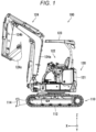
- FIG. 1 is a side view showing an example of the construction machine 100.
- the construction machine 100 is, for example, an excavator.
- a direction from the right to the left is a positive direction of an X-axis
- a direction from the rear to the front is a positive direction of a Y-axis
- a direction from the bottom to the top is a positive direction of a Z-axis.
- the construction machine 100 includes a lower traveling body 110 and an upper turning body 120.
- the upper turning body 120 is turnable relative to the lower traveling body 110.
- the lower traveling body 110 includes a traveling mechanism 112 and a blade 114.
- the traveling mechanism 112 is of a crawler type.
- the blade 114 is used for a soil discharging work and a ground leveling work.
- the upper turning body 120 includes a hood 121, a steering unit 122, a canopy 123, and a work machine 124.
- the hood 121, the steering unit 122, and the canopy 123 are arranged on an upper portion of the upper turning body 120.
- the hood 121 forms a substantially semi-cylindrical exterior of the upper turning body 120.
- the steering unit 122 enables an operator to steer the construction machine 100.
- the canopy 123 is provided as a canopy for the operator.
- the work machine 124 is arranged on the front side of the upper turning body 120.
- the work machine 124 includes a boom 124a, an arm 124b, and a bucket 124c.
- the boom 124a, the arm 124b, and the bucket 124c are driven by a hydraulic device in a well-known manner.
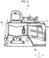
- Fig. 2 is a view showing an example of the appearance of the right rear portion of the upper turning body 120.
- the hood 121 has an exhaust opening 200.
- the exhaust opening 200 is covered with a grill 210 having a quadrangular shape.
- Fig. 3 is a plan view schematically showing an example of the component arrangement in the engine room 300.
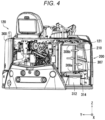
- Fig. 4 is a view showing a state in which part of the hood 121 is removed from the configuration of Fig. 2 , and shows an example of arrangement of a battery 312 and a fuse box 314.
- Fig. 5 is an enlarged perspective view of the battery 312 and the fuse box 314.
- the engine room 300 is defined below a driver's seat by the hood 121.
- an engine 302 a cooling fan 304, a radiator 306, a lower partition plate 308a, an upper partition plate 308b, a hydraulic oil tank 310, the battery 312, and the fuse box 314 are arranged.
- the radiator 306 is equivalent to an example of a "heat exchanger.”
- the engine 302 is a power source for the construction machine 100, and, for example, is a diesel engine.
- the engine 302 has an electric device.
- the cooling fan 304 and a not-shown hydraulic oil pump are assembled to an output shaft of the engine 302.
- the radiator 306 is arranged between the cooling fan 304 and the exhaust opening 200, and is supplied with coolant for the engine 302. Air sucked through a not-shown suction opening by the suction force of the cooling fan 304 passes through the engine 302, and exchanges heat with the radiator 306.
- the lower partition plate 308a and the upper partition plate 308b are plates having a substantially triangular shape.
- each of the lower partition plate 308a and the upper partition plate 308b is curved so as to contact the inner surface of the hood 121.
- the hydraulic oil tank 310 is arranged adjacent to the lower partition plate 308a and the upper partition plate 308b on the machine body front side, and stores hydraulic oil discharged from the hydraulic oil pump.
- the lower partition plate 308a and the upper partition plate 308b form an air discharge passage 307 between the radiator 306 and the exhaust opening 200.
- the lower partition plate 308a and the upper partition plate 308b are inclined upward in a direction from the radiator 306 toward the exhaust opening 200.
- the direction of air discharged from the hood 121 through the exhaust opening 200 is obliquely upward as indicated by arrows in Fig. 4 .
- the battery 312 is arranged in a space below the lower partition plate 308a, and supplies power to the electric device of the engine 302.
- the fuse box 314 is attached to the surface, which faces downward, of the lower partition plate 308a at a position adjacent to the hood 121, and is connected to a circuit connecting the electric device of the engine 302 and the battery 312 to each other.
- the battery 312 has a positive terminal 312a and a negative terminal 312b.
- the fuse box 314 is arranged in a space between the positive terminal 312a and the negative terminal 312b.
- the fuse box 314 has a center portion 314a, a first attachment portion 314b at one end, and a second attachment portion 314c at the other end.
- the fuse box 314 is attached to the surface, which faces downward, of the lower partition plate 308a through the first attachment portion 314b and the second attachment portion 314c, and the center portion 314a is separated from the lower partition plate 308a in order to dissipate heat.
- the fuse box 314 houses a first fuse and a second fuse.
- the first fuse is connected to a circuit that discharges the current of the battery 312.
- the first fuse includes a fuse connected to a circuit of a starting motor for starting the engine 302.
- the first fuse includes a fuse connected to a circuit of a glow plug for easily starting the engine 302 in a cold state.
- the second fuse is connected to a circuit that charges the battery 312.
- the second fuse includes a fuse connected to a circuit of an alternator which is a generator.
- Fig. 6 is a view showing another example of the arrangement of the battery 312 and the fuse box 314.
- Fig. 7 is a view showing the battery 312 and the fuse box 314 of Fig. 6 from another direction.
- the fuse box 314 is arranged, together with the battery 312, at a position adjacent to the hood 121 in a space below the lower partition plate 308a. Specifically, the fuse box 314 is attached to the side surface of the hydraulic oil tank 310 adjacent to the battery 312.
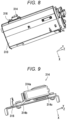
- Fig. 8 is an enlarged perspective view of the hydraulic oil tank 310 and the fuse box 314.
- Fig. 9 is an enlarged perspective view of the fuse box 314 and a mounting bracket 316.
- the mounting bracket 316 is interposed between the fuse box 314 and the hydraulic oil tank 310.
- the fuse box 314 is attached to the surface of the mounting bracket 316 through the first attachment portion 314b and the second attachment portion 314c, and the center portion 314a is separated from the mounting bracket 316 in order to dissipate heat.
- the mounting bracket 316 has two legs, and these legs are welded to the side surface of the hydraulic oil tank 310.
- the lower partition plate 308a and the upper partition plate 308b form the air discharge passage 307, and the battery 312 is arranged in the space below the lower partition plate 308a.
- the fuse box 314 is arranged between the lower partition plate 308a and the battery 312.
- the heat exchanger arranged between the cooling fan 304 and the exhaust opening 200 is the radiator 306, but the present invention is not limited thereto.
- the heat exchanger may be an oil cooler for cooling hydraulic oil.
- the fuse box 314 is attached to the side surface of the hydraulic oil tank 310, but the present invention is not limited thereto. In a case where a fuel tank storing fuel for the engine 302 is located adjacent to the battery 312, the fuse box 314 may be attached to the side surface of the combustion tank.
- the present invention is applicable to the field of construction machines.
Landscapes
- Engineering & Computer Science (AREA)
- Mining & Mineral Resources (AREA)
- Civil Engineering (AREA)
- General Engineering & Computer Science (AREA)
- Structural Engineering (AREA)
- Mechanical Engineering (AREA)
- Component Parts Of Construction Machinery (AREA)
- Cooling, Air Intake And Gas Exhaust, And Fuel Tank Arrangements In Propulsion Units (AREA)
Abstract
Description
- The present invention relates to a construction machine.
- In a construction machine described in Patent Document 1, a fuel tank is arranged adjacent to the front of an engine arranged at a rear portion, and a battery and a fuse box are arranged at the side of the fuel tank.
- Patent Document 1:
JP-A-2007-77700 - In the construction machine described in Patent Document 1, not only a harness connecting an engine-related electric device to the battery and the fuse box is long, but also it is hard to say that the space of an engine room housing the engine is effectively utilized.
- An object of the present invention is to provide a construction machine of which the component layout efficiency in an engine room is improved.
- The construction machine of the present invention includes an engine, a cooling fan, a hood, a heat exchanger, a partition plate, a battery, and a fuse box. The engine has an electric device. The cooling fan is assembled to the engine. The hood has an exhaust opening. The heat exchanger is arranged between the cooling fan and the exhaust opening. The partition plate forms an air discharge passage between the heat exchanger and the exhaust opening. The battery is arranged in a space below the partition plate. The fuse box is connected to a circuit connecting the electric device and the battery to each other. The fuse box is arranged between the battery and the partition plate.
- According to the present invention, the construction machine of which the component layout efficiency in the engine room is improved is provided.
-
-
Fig. 1 is a side view showing an example of a construction machine according to an embodiment. -
Fig. 2 is a view showing an example of the appearance of a right rear portion of an upper turning body. -
Fig. 3 is a plan view schematically showing an example of component arrangement in an engine room. -
Fig. 4 is a view showing an example of arrangement of a battery and a fuse box. -
Fig. 5 is an enlarged perspective view of the battery and the fuse box. -
Fig. 6 is a view showing another example of the arrangement of the battery and the fuse box. -
Fig. 7 is a view showing the battery and the fuse box ofFig. 6 from another direction. -
Fig. 8 is an enlarged perspective view of a hydraulic oil tank and the fuse box. -
Fig. 9 is an enlarged perspective view of the fuse box and a mounting bracket. - An embodiment of the present invention will be described with reference to the drawings. Note that in the drawings, the same reference numerals are used to represent the same or equivalent elements and description thereof will not be repeated.
- A
construction machine 100 according to the embodiment will be described with reference toFig. 1. Fig. 1 is a side view showing an example of theconstruction machine 100. Theconstruction machine 100 is, for example, an excavator. For the sake of convenience, inFig. 1 , a direction from the right to the left is a positive direction of an X-axis, a direction from the rear to the front is a positive direction of a Y-axis, and a direction from the bottom to the top is a positive direction of a Z-axis. - As shown in
Fig. 1 , theconstruction machine 100 includes a lowertraveling body 110 and an upper turningbody 120. The upper turningbody 120 is turnable relative to the lowertraveling body 110. - The lower
traveling body 110 includes atraveling mechanism 112 and ablade 114. Thetraveling mechanism 112 is of a crawler type. Theblade 114 is used for a soil discharging work and a ground leveling work. - The upper turning
body 120 includes ahood 121, asteering unit 122, acanopy 123, and awork machine 124. - The
hood 121, thesteering unit 122, and thecanopy 123 are arranged on an upper portion of the upper turningbody 120. Thehood 121 forms a substantially semi-cylindrical exterior of the upper turningbody 120. Thesteering unit 122 enables an operator to steer theconstruction machine 100. Thecanopy 123 is provided as a canopy for the operator. - The
work machine 124 is arranged on the front side of the upper turningbody 120. Thework machine 124 includes aboom 124a, anarm 124b, and abucket 124c. Theboom 124a, thearm 124b, and thebucket 124c are driven by a hydraulic device in a well-known manner. - Next, the appearance of a right rear portion of the upper turning
body 120 will be described with reference toFigs. 1 and2. Fig. 2 is a view showing an example of the appearance of the right rear portion of the upper turningbody 120. - As shown in
Fig. 2 , thehood 121 has an exhaust opening 200. Theexhaust opening 200 is covered with agrill 210 having a quadrangular shape. - Next, component arrangement in an
engine room 300 will be described with reference toFigs. 1 to 5 .Fig. 3 is a plan view schematically showing an example of the component arrangement in theengine room 300.Fig. 4 is a view showing a state in which part of thehood 121 is removed from the configuration ofFig. 2 , and shows an example of arrangement of abattery 312 and afuse box 314.Fig. 5 is an enlarged perspective view of thebattery 312 and thefuse box 314. - As shown in
Figs. 3 and4 , theengine room 300 is defined below a driver's seat by thehood 121. In theengine room 300, anengine 302, acooling fan 304, aradiator 306, alower partition plate 308a, anupper partition plate 308b, ahydraulic oil tank 310, thebattery 312, and thefuse box 314 are arranged. Theradiator 306 is equivalent to an example of a "heat exchanger." - The
engine 302 is a power source for theconstruction machine 100, and, for example, is a diesel engine. Theengine 302 has an electric device. Thecooling fan 304 and a not-shown hydraulic oil pump are assembled to an output shaft of theengine 302. Theradiator 306 is arranged between the coolingfan 304 and theexhaust opening 200, and is supplied with coolant for theengine 302. Air sucked through a not-shown suction opening by the suction force of the coolingfan 304 passes through theengine 302, and exchanges heat with theradiator 306. Thelower partition plate 308a and theupper partition plate 308b are plates having a substantially triangular shape. One side of each of thelower partition plate 308a and theupper partition plate 308b is curved so as to contact the inner surface of thehood 121. Thehydraulic oil tank 310 is arranged adjacent to thelower partition plate 308a and theupper partition plate 308b on the machine body front side, and stores hydraulic oil discharged from the hydraulic oil pump. - As shown in
Fig. 4 , thelower partition plate 308a and theupper partition plate 308b form anair discharge passage 307 between theradiator 306 and theexhaust opening 200. Moreover, thelower partition plate 308a and theupper partition plate 308b are inclined upward in a direction from theradiator 306 toward theexhaust opening 200. Thus, the direction of air discharged from thehood 121 through theexhaust opening 200 is obliquely upward as indicated by arrows inFig. 4 . - The
battery 312 is arranged in a space below thelower partition plate 308a, and supplies power to the electric device of theengine 302. Thefuse box 314 is attached to the surface, which faces downward, of thelower partition plate 308a at a position adjacent to thehood 121, and is connected to a circuit connecting the electric device of theengine 302 and thebattery 312 to each other. - As shown in
Fig. 5 , thebattery 312 has apositive terminal 312a and anegative terminal 312b. Thefuse box 314 is arranged in a space between thepositive terminal 312a and thenegative terminal 312b. - The
fuse box 314 has acenter portion 314a, afirst attachment portion 314b at one end, and asecond attachment portion 314c at the other end. Thefuse box 314 is attached to the surface, which faces downward, of thelower partition plate 308a through thefirst attachment portion 314b and thesecond attachment portion 314c, and thecenter portion 314a is separated from thelower partition plate 308a in order to dissipate heat. - The
fuse box 314 houses a first fuse and a second fuse. The first fuse is connected to a circuit that discharges the current of thebattery 312. The first fuse includes a fuse connected to a circuit of a starting motor for starting theengine 302. Moreover, the first fuse includes a fuse connected to a circuit of a glow plug for easily starting theengine 302 in a cold state. The second fuse is connected to a circuit that charges thebattery 312. The second fuse includes a fuse connected to a circuit of an alternator which is a generator. - Next, another example of the arrangement of the
battery 312 and thefuse box 314 will be described with reference toFigs. 1 to 3 ,6 , and7 .Fig. 6 is a view showing another example of the arrangement of thebattery 312 and thefuse box 314.Fig. 7 is a view showing thebattery 312 and thefuse box 314 ofFig. 6 from another direction. - As shown in
Figs. 6 and7 , thefuse box 314 is arranged, together with thebattery 312, at a position adjacent to thehood 121 in a space below thelower partition plate 308a. Specifically, thefuse box 314 is attached to the side surface of thehydraulic oil tank 310 adjacent to thebattery 312. -
Fig. 8 is an enlarged perspective view of thehydraulic oil tank 310 and thefuse box 314.Fig. 9 is an enlarged perspective view of thefuse box 314 and a mountingbracket 316. - As shown in
Figs. 8 and 9 , the mountingbracket 316 is interposed between thefuse box 314 and thehydraulic oil tank 310. Thefuse box 314 is attached to the surface of the mountingbracket 316 through thefirst attachment portion 314b and thesecond attachment portion 314c, and thecenter portion 314a is separated from the mountingbracket 316 in order to dissipate heat. The mountingbracket 316 has two legs, and these legs are welded to the side surface of thehydraulic oil tank 310. - According to the above-described embodiment, the
lower partition plate 308a and theupper partition plate 308b form theair discharge passage 307, and thebattery 312 is arranged in the space below thelower partition plate 308a. Moreover, thefuse box 314 is arranged between thelower partition plate 308a and thebattery 312. Thus, theconstruction machine 100 of which the component layout efficiency in theengine room 300 is improved is provided. In addition, thefuse box 314 is easily accessible from the outside, and therefore, maintainability is improved. - The embodiment of the present invention has been described above with reference to the drawings. Note that the present invention is not limited to the above-described embodiment and can be implemented in various forms without departing from the gist of the invention. In addition, various aspects of the invention can be made by appropriately combining a plurality of components disclosed above in the embodiment. For example, some components may be omitted from all the components described in the embodiment. For the sake of easy understanding, the drawings schematically show each component, and, e.g., the number of each component shown may be different from an actual number for the sake of convenience in preparation of the drawings. In addition, each component described above in the embodiment is an example and is not particularly limited, and various changes can be made without substantially departing from the advantageous effects of the present invention.
- In the embodiment, the heat exchanger arranged between the cooling
fan 304 and theexhaust opening 200 is theradiator 306, but the present invention is not limited thereto. The heat exchanger may be an oil cooler for cooling hydraulic oil. - In the embodiment, the
fuse box 314 is attached to the side surface of thehydraulic oil tank 310, but the present invention is not limited thereto. In a case where a fuel tank storing fuel for theengine 302 is located adjacent to thebattery 312, thefuse box 314 may be attached to the side surface of the combustion tank. - The present invention is applicable to the field of construction machines.
-
- 100
- Construction Machine
- 121
- Hood
- 200
- Exhaust Opening
- 300
- Engine Room
- 302
- Engine
- 304
- Cooling Fan
- 306
- Radiator (Heat Exchanger)
- 307
- Air Discharge Passage
- 308a
- Lower Partition Plate
- 308b
- Upper Partition Plate
- 310
- Hydraulic Oil Tank
- 312
- Battery
- 312a
- Positive Terminal
- 312b
- Negative Terminal
- 314
- Fuse Box
- 314a
- Center Portion
- 314b
- First Attachment Portion
- 314c
- Second Attachment Portion
- 316
- Mounting Bracket
Claims (6)
- A construction machine comprising:an engine that has an electric device;a cooling fan that is assembled to the engine;a hood that has an exhaust opening;a heat exchanger that is arranged between the cooling fan and the exhaust opening;a partition plate that forms an air discharge passage between the heat exchanger and the exhaust opening;a battery that is arranged in a space below the partition plate; anda fuse box that is connected to a circuit connecting the electric device and the battery to each other,wherein the fuse box is arranged between the battery and the partition plate.
- The construction machine according to claim 1, wherein the fuse box is attached to a surface of the partition plate.
- The construction machine according to claim 2, whereinthe fuse box has a center portion and attachment portions at both ends, andthe fuse box is arranged on the partition plate through the attachment portions, and the center portion is separated from the partition plate.
- The construction machine according to any one of claims 1 to 3, wherein the fuse box is arranged in a space between a positive terminal and a negative terminal of the battery.
- The construction machine according to any one of claims 1 to 4, whereinthe fuse box housesa first fuse that is connected to a circuit that discharges a current of the battery; anda second fuse that is connected to a circuit that charges the battery.
- The construction machine according any one of claims 1 to 5, wherein the partition plate is inclined upward in a direction from the heat exchanger toward the exhaust opening.
Applications Claiming Priority (2)
| Application Number | Priority Date | Filing Date | Title |
|---|---|---|---|
| JP2020212336A JP7530819B2 (en) | 2020-12-22 | 2020-12-22 | Construction Machinery |
| PCT/JP2021/044834 WO2022138126A1 (en) | 2020-12-22 | 2021-12-07 | Construction machine |
Publications (2)
| Publication Number | Publication Date |
|---|---|
| EP4269706A1 true EP4269706A1 (en) | 2023-11-01 |
| EP4269706A4 EP4269706A4 (en) | 2024-11-27 |
Family
ID=82159617
Family Applications (1)
| Application Number | Title | Priority Date | Filing Date |
|---|---|---|---|
| EP21910275.3A Pending EP4269706A4 (en) | 2020-12-22 | 2021-12-07 | CONSTRUCTION MACHINE |
Country Status (4)
| Country | Link |
|---|---|
| US (1) | US12553213B2 (en) |
| EP (1) | EP4269706A4 (en) |
| JP (2) | JP7530819B2 (en) |
| WO (1) | WO2022138126A1 (en) |
Families Citing this family (2)
| Publication number | Priority date | Publication date | Assignee | Title |
|---|---|---|---|---|
| JP7305843B2 (en) * | 2020-12-09 | 2023-07-10 | マクセル株式会社 | receiver |
| JP7530819B2 (en) | 2020-12-22 | 2024-08-08 | ヤンマーホールディングス株式会社 | Construction Machinery |
Family Cites Families (17)
| Publication number | Priority date | Publication date | Assignee | Title |
|---|---|---|---|---|
| JP3330517B2 (en) * | 1997-05-19 | 2002-09-30 | 富士通株式会社 | Protection circuit and battery unit |
| JP4561520B2 (en) * | 2004-07-31 | 2010-10-13 | 住友電装株式会社 | Electrical junction box |
| JP2007077700A (en) | 2005-09-15 | 2007-03-29 | Shin Caterpillar Mitsubishi Ltd | Wiring structure in construction machinery |
| KR100656068B1 (en) * | 2005-12-27 | 2006-12-11 | 두산인프라코어 주식회사 | Excavator chiller |
| JP4948314B2 (en) * | 2007-08-02 | 2012-06-06 | ヤンマー株式会社 | Swivel work vehicle |
| JP2009056918A (en) * | 2007-08-31 | 2009-03-19 | Iseki & Co Ltd | Work vehicle |
| JP5158967B2 (en) * | 2008-10-29 | 2013-03-06 | 矢崎総業株式会社 | Fuse box directly above the battery |
| JP2013087542A (en) * | 2011-10-20 | 2013-05-13 | Hitachi Constr Mach Co Ltd | Construction machine |
| JP5631842B2 (en) * | 2011-10-24 | 2014-11-26 | 日立建機株式会社 | Construction machinery |
| JP5867193B2 (en) * | 2012-03-13 | 2016-02-24 | コベルコ建機株式会社 | Upper swing body of construction machinery |
| JP6133111B2 (en) * | 2013-02-25 | 2017-05-24 | 本田技研工業株式会社 | Battery arrangement structure for saddle-ride type vehicles |
| JP6260298B2 (en) * | 2014-01-24 | 2018-01-17 | コベルコ建機株式会社 | Construction machinery |
| JP6189241B2 (en) * | 2014-03-26 | 2017-08-30 | 株式会社クボタ | Working machine |
| JP6738750B2 (en) * | 2017-02-22 | 2020-08-12 | 株式会社竹内製作所 | Work vehicle |
| US11413955B2 (en) * | 2018-06-29 | 2022-08-16 | Kubota Corporation | Working machine |
| JP7530819B2 (en) | 2020-12-22 | 2024-08-08 | ヤンマーホールディングス株式会社 | Construction Machinery |
| JP2025006871A (en) * | 2023-06-30 | 2025-01-17 | 株式会社クボタ | Work equipment |
-
2020
- 2020-12-22 JP JP2020212336A patent/JP7530819B2/en active Active
-
2021
- 2021-12-07 US US18/269,140 patent/US12553213B2/en active Active
- 2021-12-07 WO PCT/JP2021/044834 patent/WO2022138126A1/en not_active Ceased
- 2021-12-07 EP EP21910275.3A patent/EP4269706A4/en active Pending
-
2024
- 2024-06-20 JP JP2024099430A patent/JP2024114753A/en active Pending
Also Published As
| Publication number | Publication date |
|---|---|
| JP7530819B2 (en) | 2024-08-08 |
| US20240084551A1 (en) | 2024-03-14 |
| US12553213B2 (en) | 2026-02-17 |
| WO2022138126A1 (en) | 2022-06-30 |
| JP2024114753A (en) | 2024-08-23 |
| EP4269706A4 (en) | 2024-11-27 |
| JP2022098755A (en) | 2022-07-04 |
Similar Documents
| Publication | Publication Date | Title |
|---|---|---|
| JP4956687B2 (en) | Hybrid work vehicle | |
| JP2024114753A (en) | Construction Machinery | |
| KR101751086B1 (en) | Electrical construction machine | |
| CN103370515B (en) | Enclosed type engine-type working machine | |
| EP1775392B1 (en) | Construction machine | |
| EP2902549A1 (en) | Construction machine with a cooling means for an electrical component | |
| EP4170098B1 (en) | Electric work machine techinical field | |
| CN117306628A (en) | Electric working machine | |
| EP4299838A2 (en) | Electric work machine | |
| CN117403715A (en) | Electric working machine | |
| JP4042779B2 (en) | Hybrid construction machine | |
| US12618224B2 (en) | Electric work machine | |
| EP4269149A1 (en) | Construction machine | |
| JP2011190566A (en) | Partitioning structure inside engine room | |
| US11821173B2 (en) | Inverter location and orientation within a mobile machine | |
| US12371876B2 (en) | Work machine | |
| JP2001342644A (en) | Structure of frame inside of turning work vehicle | |
| CN120331324A (en) | Electric working machinery | |
| EP4624671A1 (en) | Working vehicle | |
| CN117306630A (en) | Electric working machine | |
| JP2003193509A (en) | Cooling device in construction equipment | |
| KR20260051958A (en) | Working machine | |
| JP2024078568A (en) | Electrical work machines | |
| KR20240010429A (en) | Electric work machine | |
| JP2024142726A (en) | Construction Machinery |
Legal Events
| Date | Code | Title | Description |
|---|---|---|---|
| STAA | Information on the status of an ep patent application or granted ep patent |
Free format text: STATUS: THE INTERNATIONAL PUBLICATION HAS BEEN MADE |
|
| PUAI | Public reference made under article 153(3) epc to a published international application that has entered the european phase |
Free format text: ORIGINAL CODE: 0009012 |
|
| STAA | Information on the status of an ep patent application or granted ep patent |
Free format text: STATUS: REQUEST FOR EXAMINATION WAS MADE |
|
| 17P | Request for examination filed |
Effective date: 20230703 |
|
| AK | Designated contracting states |
Kind code of ref document: A1 Designated state(s): AL AT BE BG CH CY CZ DE DK EE ES FI FR GB GR HR HU IE IS IT LI LT LU LV MC MK MT NL NO PL PT RO RS SE SI SK SM TR |
|
| DAV | Request for validation of the european patent (deleted) | ||
| DAX | Request for extension of the european patent (deleted) | ||
| A4 | Supplementary search report drawn up and despatched |
Effective date: 20241025 |
|
| RIC1 | Information provided on ipc code assigned before grant |
Ipc: B60R 16/02 20060101ALI20241021BHEP Ipc: E02F 9/00 20060101AFI20241021BHEP |
|
| GRAP | Despatch of communication of intention to grant a patent |
Free format text: ORIGINAL CODE: EPIDOSNIGR1 |
|
| STAA | Information on the status of an ep patent application or granted ep patent |
Free format text: STATUS: GRANT OF PATENT IS INTENDED |