EP4269701B1 - Selbstnivellierende ausrüstung zur manipulation fester oberflächen - Google Patents
Selbstnivellierende ausrüstung zur manipulation fester oberflächen Download PDFInfo
- Publication number
- EP4269701B1 EP4269701B1 EP23150679.1A EP23150679A EP4269701B1 EP 4269701 B1 EP4269701 B1 EP 4269701B1 EP 23150679 A EP23150679 A EP 23150679A EP 4269701 B1 EP4269701 B1 EP 4269701B1
- Authority
- EP
- European Patent Office
- Prior art keywords
- frame
- equipment
- bulkhead
- main plane
- support
- Prior art date
- Legal status (The legal status is an assumption and is not a legal conclusion. Google has not performed a legal analysis and makes no representation as to the accuracy of the status listed.)
- Active
Links
Images

Classifications
-
- E—FIXED CONSTRUCTIONS
- E02—HYDRAULIC ENGINEERING; FOUNDATIONS; SOIL SHIFTING
- E02F—DREDGING; SOIL-SHIFTING
- E02F3/00—Dredgers; Soil-shifting machines
- E02F3/04—Dredgers; Soil-shifting machines mechanically-driven
- E02F3/18—Dredgers; Soil-shifting machines mechanically-driven with digging wheels turning round an axis, e.g. bucket-type wheels
- E02F3/183—Dredgers; Soil-shifting machines mechanically-driven with digging wheels turning round an axis, e.g. bucket-type wheels with digging unit shiftable relative to the frame
-
- E—FIXED CONSTRUCTIONS
- E01—CONSTRUCTION OF ROADS, RAILWAYS, OR BRIDGES
- E01C—CONSTRUCTION OF, OR SURFACES FOR, ROADS, SPORTS GROUNDS, OR THE LIKE; MACHINES OR AUXILIARY TOOLS FOR CONSTRUCTION OR REPAIR
- E01C23/00—Auxiliary devices or arrangements for constructing, repairing, reconditioning, or taking-up road or like surfaces
- E01C23/06—Devices or arrangements for working the finished surface; Devices for repairing or reconditioning the surface of damaged paving; Recycling in place or on the road
- E01C23/08—Devices or arrangements for working the finished surface; Devices for repairing or reconditioning the surface of damaged paving; Recycling in place or on the road for roughening or patterning; for removing the surface down to a predetermined depth high spots or material bonded to the surface, e.g. markings; for maintaining earth roads, clay courts or like surfaces by means of surface working tools, e.g. scarifiers, levelling blades
- E01C23/085—Devices or arrangements for working the finished surface; Devices for repairing or reconditioning the surface of damaged paving; Recycling in place or on the road for roughening or patterning; for removing the surface down to a predetermined depth high spots or material bonded to the surface, e.g. markings; for maintaining earth roads, clay courts or like surfaces by means of surface working tools, e.g. scarifiers, levelling blades using power-driven tools, e.g. vibratory tools
- E01C23/088—Rotary tools, e.g. milling drums
-
- E—FIXED CONSTRUCTIONS
- E02—HYDRAULIC ENGINEERING; FOUNDATIONS; SOIL SHIFTING
- E02F—DREDGING; SOIL-SHIFTING
- E02F3/00—Dredgers; Soil-shifting machines
- E02F3/04—Dredgers; Soil-shifting machines mechanically-driven
- E02F3/18—Dredgers; Soil-shifting machines mechanically-driven with digging wheels turning round an axis, e.g. bucket-type wheels
- E02F3/188—Dredgers; Soil-shifting machines mechanically-driven with digging wheels turning round an axis, e.g. bucket-type wheels with the axis being horizontal and transverse to the direction of travel
-
- E—FIXED CONSTRUCTIONS
- E02—HYDRAULIC ENGINEERING; FOUNDATIONS; SOIL SHIFTING
- E02F—DREDGING; SOIL-SHIFTING
- E02F5/00—Dredgers or soil-shifting machines for special purposes
- E02F5/02—Dredgers or soil-shifting machines for special purposes for digging trenches or ditches
- E02F5/08—Dredgers or soil-shifting machines for special purposes for digging trenches or ditches with digging wheels turning round an axis
Definitions
- the present invention relates to a self-levelling equipment for manipulating solid surfaces of the type specified in the preamble to the first claim.
- the present invention has as its object a milling machine suitable for being installed on a self-propelled machine to enable the removal or milling of a solid surface layer, for example made of asphalt or concrete.
- auxiliary devices generally installed on self-propelled machines and used to remove or mill off predetermined portions of a solid surface that may be, for example, a road surface, soil or other solid pavement.
- the milling machines allow a layer of the solid surface to be manipulated in order to restore, or excavate for subsequent filling, the surface.
- the milling machines of the known technique may comprise lateral support elements to the solid surface, essentially skids, which run on the surface and control the relative position between the cutting edges and the surface, in particular by keeping the depth of the cutting edges constant even when the milling machine varies its inclination with respect to the support surface.
- the milling machines are therefore called self-levelling.
- Such milling machines are described, for example, in patent documents IT1019900790697 , EP-B-3191647 , EP-B-1222333 and US-A-2019/127930 .
- milling machines comprising working or digging means rotatably supported by a main frame, and a adjustment frame defining at least one substantially flat contact portion suitable for contacting a corresponding portion of the surface to be machined, wherein the position of the adjustment frame with respect to the main support frame can be set so as to control the working depth of the working means.
- the movement of the adjustment frame is performed by means of adjustment means comprising a first attachment arm articulated on the support frame by means of a first attachment pin extending from the first attachment arm in such a way that rotating the first attachment arm around the pin in two opposite directions of rotation results in translation of the adjustment frame.
- the adjustment frame is fixed to the main support frame in such a way as to be translatable with respect to the main support frame in a plane perpendicular to the rotation axis of the working or digging means or rotatable with respect to the main support frame in a main rotation axis substantially parallel to the rotation axis of the digging means.
- the main support frame and the adjustment frame are coupled together by means of a first engagement pin and guiding means.
- the first engagement pin extends along a direction parallel to the main rotation axis and comprises at least one free end portion engaged in a first engagement slot extending along an arched, or semi-circular shape, suitable to allow the engagement pin to translate along the first engagement slot.
- the guiding means comprise a proximity portion, extending along a direction substantially parallel to the rotation plane of the working or digging means, and an end portion, shaped like a plate extending from the proximity portion substantially parallel to the rotation plane of the working or digging means, defining therebetween an engagement gap in which a portion of the adjustment frame is smoothly received.
- the end portion interacting with the engagement guides and pins does not allow the adjustment frame to be stably engaged to the main frame especially when the adjustment frame is subjected to vibratory transverse forces.
- the technical task underlying the present invention is to devise a self-levelling equipment for manipulating solid surfaces capable of substantially obviating at least part of the aforementioned drawbacks.
- the measurements, values, shapes and geometric references (such as perpendicularity and parallelism), when associated with words like "about” or other similar terms such as “approximately” or “substantially”, are to be considered as except for measurement errors or inaccuracies due to production and/or manufacturing errors, and, above all, except for a slight divergence from the value, measurements, shape, or geometric reference with which it is associated.
- these terms if associated with a value, preferably indicate a divergence of not more than 10% of the value.
- treatment refers to the action and/or processes of a computer or similar electronic calculation device that manipulates and/or transforms data represented as physical, such as electronic quantities of registers of a computer system and/or memories in, other data similarly represented as physical quantities within computer systems, registers or other storage, transmission or information displaying devices.
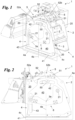
- the self-levelling equipment for manipulating solid surfaces is globally referred to as 1.
- the equipment 1 is substantially adapted to be installed on a self-propelled machine.
- the self-propelled machine may comprise the equipment 1 in addition to the organs known to enable self-propelled machines to move on a surface.
- the equipment 1 is adapted, when in use on a self-propelled machine in motion, to allow the removal or milling of a solid surface or, more accurately, a solid surface layer of selectable thickness or depth.
- the solid surface may be flat, curved or even irregular. It may, for example, be defined by a road surface and may, therefore, be made of asphalt or concrete.
- the equipment 1 comprises at least one frame 2.
- the frame 2 is essentially the portion of the equipment 1 capable of being integrally constrained to the self-propelled machine.
- the frame 2 is configured to be operatively connected to a self-propelled machine.
- the frame 2 may comprise constraining means configured to allow the overall equipment 1 to be constrained to the machine, for example at a front area of the machine.
- the constraining means may, for example, comprise a mechanical hinge with adjustable friction and suitable for connection to a lifting arm.
- the frame 2 is preferably a support frame. Thus, it is suitable for supporting the components of the equipment 1.
- the frame 2 may define shapes of various kinds.
- the frame 2 comprises at least a first bulkhead 20.
- the first bulkhead 20 is substantially a plate element, expanding predominantly along a plane and defining dimensions on the plane that are significantly larger than the third dimension transverse to the plane.
- the first bulkhead 20 is preferably transverse to the ground, when the equipment 1 is in use.
- ground preferably means, naturally, the solid surface on which the equipment 1 moves.
- the frame 2 may also include a pair of first bulkheads 20.
- the first bulkheads 20, if present in pairs, may expand parallel in such a way as to define, between them, a housing space. The latter, therefore, may contain one or more other components of the equipment 1. If present in pairs, preferably, the first bulkheads 20 are independent of each other.
- the equipment comprises manipulating means 3.
- the manipulating means 3 are substantially configured to manipulate the solid surface when the equipment 1 is in use.
- the manipulating means 3 are adapted to scratch the solid surface by means of elements moved relative to the solid surface.
- the manipulating means 3 enable at least the removal or scarification of a surface layer of the solid surface.
- the manipulating means 3 are connected in a compliant way to the frame 2.
- the manipulating means 3 are configured to rotate, relative to the frame 2, around a rotation axis 3a.
- the rotation axis 3a is preferably, but not necessarily, approximately parallel to the ground. Also preferably, the rotation axis 3a is transverse to the first bulkhead 20.
- the rotation axis 3a may, for example, be determined by a shaft rotating relative to the frame 2 and integral with at least part of the manipulating means 3.
- the rotation axis 3a may be transverse to both first bulkheads 20.
- the manipulating means 3 may be positioned at least partially in the housing space defined between the first bulkheads 20.
- the manipulating means 3 comprise a shaft rotating around the rotation axis 3a, it may be constrained to the frame 2 between the first bulkheads 20.
- the manipulating means 3 may comprise a toothed wheel integral with the shaft. Furthermore, the wheel may be configured to rotate so that the movement of the teeth relative to the solid surface is equivalent with respect to the movement of the driving machine, when the equipment 1 is in use.
- the equipment 1 or the driving machine may also comprise handling means, for example motors, configured to control the rotation of the handling means 3 about the rotation axis 3a.
- handling means for example motors, configured to control the rotation of the handling means 3 about the rotation axis 3a.
- Similar devices are, however, extremely well known to the person skilled in the art and are not particular subject matter of the present patent application.
- the equipment 1 therefore also includes support means 4.
- the support means 4 are substantially the portion of the equipment 1 that allows for levelling the frame 2, and thus also the manipulation depth of the manipulating means 3, with respect to the solid surface.
- the support means 4 are preferably constrained in a compliant way to the frame 2.
- the support means 4 are constrained to the frame 2 in such a way that they can move, relative to the frame 2, at least along a main plane 4a.
- the main plane 4a is preferably transverse to the rotation axis 3a.
- the main plane 4a may be just normal to the rotation axis 3a.
- the main plane 4a is preferably transverse to the ground or solid surface.
- the support means 4, similarly to the frame 2, comprise at least a second bulkhead 40.
- the second bulkhead 40 is also substantially a plate element, expanding predominantly along a plane and defining significantly larger dimensions on the plane than the third dimension transverse to the plane.
- the second bulkhead 40 expands parallel to the main plane 4a. Therefore, the second bulkhead 40 is also transverse to the ground or solid surface.
- the second bulkhead 40 in particular, preferably comprises at least one support surface 41.
- the support surface 41 is configured to move, when the equipment 1 is in use, in support of the solid surface. Thus, it preferably slides on the support surface while, at the same time, supporting the frame 2 to which the support means 4 are constrained in order to maintain the manipulation depth of the manipulating means 3 constant.
- the support surface 41 may predominantly expand along a support plane 4c.
- the support plane 4c is preferably transverse to the main plane 4a and parallel to the rotation axis 3a. It is also preferably parallel to the solid surface.
- the support surface 41 therefore may be predominantly flat, but may also have curvatures.
- the support means 4 are constrained in a compliant way to the frame 2 and substantially translatable relative to it along the main plane 4a.
- the equipment 1 preferably comprises further components.
- the equipment 1 further comprises adjustment means 5.
- the adjustment means 5 are configured to adjust the relative position between frame 2 and support means 4.
- the adjustment means 5 are essentially the component of equipment 1 through which the manipulation depth of the manipulating means 3 can be controlled and determined.
- the adjustment means in brief, comprise at least one first pin 50.
- the first pin 50 preferably expands transversely to the main plane 4a. Furthermore, the first pin 50 is preferably engaged in a compliant way to the frame 2. In particular, the first pin 50 is engaged in a compliant way to the frame 2 such that it can rotate, on command, relative to the frame 2, around an axis parallel to the rotation axis 3a. Preferably, the axis around which the first pin 50 rotates relative to the frame 20 is spaced with respect to the first pin 50. In other words, the first pin 50 can rotate eccentrically with respect to the rotation axis disposed at the engagement portion with the frame 2 and is not centred with respect thereto.
- the first pin 50 is engaged to the frame 2 in an indirect manner.
- the first pin 50 is engaged to the frame 2 via a transmission element 51.
- the transmission element 51 is essentially a connecting element between the first pin 50 and the constraint portion of the frame 2 around which the first pin 50 rotates.
- the transmission element 51 may be made from a simple bar, or an annular element, or more preferably from a triangular connector.
- the latter may be hinged on the frame 2 at its own vertex.
- the triangular connector may be laboriously constrained at another vertex to the first pin 50.
- the adjustment means 5 may also comprise an arm 52.
- the arm 52 is essentially a controllable extendable element. Therefore, the arm 52 may be realised by a linear actuator, for example a piston, having a fixed part and at least linearly movable rod.
- a linear actuator for example a piston, having a fixed part and at least linearly movable rod.
- the arm 52 may be pneumatic, hydraulic, electromechanical or other.
- the arm 52 defines a first end 52a and a second end 52b.
- the first end 52a and the second end 52b are mutually opposite. Therefore, the ends 52a, 52b are capable of being reciprocally approached or moved apart on command to reduce or increase the length of the arm 52.
- the arm 52 is therefore preferably constrained, at the first end 52a, to the frame 2.
- the arm 52 is constrained to the frame 2 such that it can rotate about an axis parallel to the rotation axis 3a with respect to the frame 2.
- the arm 52 may be constrained in a compliant way to the arm 52, in detail at the second end 52b.
- the latter may be constrained to one of the vertices of the transmission element 51.
- the transmission element 51 may rotate around an axis parallel to the rotation axis 3a relative to the arm 52.
- the first pin 50 is capable of being constrained in a compliant way to the support means 4.
- the support means 4 comprise at least one first guide 42.
- the first guide 42 is preferably arranged at one side of the support means 4 opposite the support surface 41.
- the first guide 42 is substantially on the opposite side of the solid surface from the rotation axis 3a.
- the first pin 50 is therefore movably engaged in the first guide 42 and is configured to move, in proportion to its rotation relative to the frame 2 as previously described, the support means 4 relative to the frame 2 along at least one direction parallel to the main plane 2a.
- the first pin 52 when the first pin 50 is rotated with respect to the frame 2, for example by virtue of an expansion of the arm 52 imparting a rotation of the transmission element 51 and thus of the first pin 50 with respect to the frame 2, the first pin 52 is capable of dragging the support means 4 along at least one direction parallel to the main plane 4a to move the support means 4 with respect to the frame 2.
- the drive element 51 rotates about an axis parallel to the rotation axis 3a also relative to the frame 2 and support means 4.
- the first guide 42 essentially defines a movement trajectory of the first pin 50 parallel to the main plane 4a. In particular, it allows the first pin 50 to move along the trajectory between two ends of the first guide 42.
- the first guide 42 is expanded along a circumferential arc with concavity towards the support plane 4c and approximately close to the intermediate trajectory 4b. Therefore, thanks to the first guide 42, the support means 4 are free to rotate at least partially around the rotation axis 3a, while maintaining the manipulation depth of the manipulating means 3 constant with respect to the solid surface.
- the frame 2 and the support means 4 are also mutually constrained in a compliant way by means of particular elements.
- the first bulkhead 20 runs parallel to the main plane 4a.
- the first bulkhead 20 is developed parallel to the second bulkhead 40.
- the first bulkhead 20 includes at least two second pins 21.
- the second pins 21 are substantially protruding elements from the first bulkhead 20.
- the second pins 21 expand transversely to the main plane 4a. Accordingly, the second pins 21 each define a constrained end to the first bulkhead 20 and a free end.
- the second bulkhead 40 comprises two second guides 43.
- the second guides 43 are separate from each other. Furthermore, the second guides 43 are mutually spaced apart. In detail, the second guides 43 are positioned at opposite sides of the support means 4 with respect to an intermediate trajectory 4b.
- the intermediate trajectory 4b is essentially a trajectory, preferably a line, that is virtual. It is preferably defined, when the equipment 1 is in use, by the normal to the solid surface passing through the rotation axis 3a. In any case, of course, the intermediate trajectory 4b turns out to be transverse, in some cases precisely normal, to the support surface 41, in detail to the support plane 4c. Therefore, in other words, the support surface 41, the second pins 43 and the first pin 42 are distributed around the rotation axis 3a almost quadrilateral.
- the two second pins 21 are each movably engaged in a respective second guide 43, Therefore, the second guides 43 also substantially define movement trajectories for each second pin 21 parallel to the main plane 4a.
- one of the second guides 43 expands along a trajectory parallel to the main plane 4a and transverse to the support plane 4c.
- the other second guide 43 defines, on the other hand, an approximately quadrangular movement area.
- the area may be approximately parallelogram-shaped.
- the second guides allow the second pins 21 to move in the second guides 43 respectively along a single direction parallel to the main plane 4a and a plurality of directions parallel to the main plane 4a and, thus, allow the support means 4 to move relative to the frame 2 in relation to what is allowed by the second pins 21 and second guides 43.
- the guides 42, 43 could be defined by grooves made on the second bulkhead 40 within which the pins 50, 21 can be engaged. Or, each of the guides 42, 43 could be made from a through-hole defined on the second bulkhead 40.
- each or at least part of the pins 50, 21 could comprise heads, at the free ends, configured to define an obstacle to mutual movement between pins 50, 21 and rails 42, 43 transversely to the main plane 4a.
- the equipment 1 also comprises a side plate 6.
- the side plate 6 is substantially an element for stabilising the mutual movement between the frames 2, 4 in particular with reference to directions transverse to the main plane 4a.
- the side plate 6 is constrained to the second pins 21 at ends of the second pins 21 opposite the first bulkhead 20.
- the side plate 6 runs parallel to the main plane 4a.
- the side plate 6 is configured to prevent relative translations between the frame 2 and the support means 4 transversely to the main plane 4a.
- the side plate 6 may, therefore, be part of the support means 4 themselves.
- the second bulkhead 40 could comprise the side plate 6. Even more in detail, the latter could be a portion of the second bulkhead 40.
- the side plate 6 could expand between the second pins 21 at least close to the rotation axis 3a.
- the side plate 6 could be a portion of the second bulkhead 40 defining a substantially L-shape and the second pins 21 could be constrained at ends of the side plate 6.
- the frame 2 could comprise the side plate 6.
- the second bulkhead 40 is distinct from the side plate 6. Furthermore, the second bulkhead 40 is engaged between the first bulkhead 20 and the side plate 6.
- the side plate 6 may expand between the second pins 21 at least close to the rotation axis 3a.
- the side plate 6 may, also in this embodiment, define a substantially L-shape and the second pins 21 may be constrained at the ends of the side plate 6.
- the frame 2 may comprise a pair of first bulkheads 20.
- the support means 4 also comprise a pair of second bulkheads 40. If present in pairs, preferably, the second bulkheads 40 are separate and distinct from each other. Accordingly, each of the second bulkheads 40 may move relative to the frame 2, in particular to a first bulkhead 20, independently of each other. Alternatively, the second bulkheads 40 may also be integral with each other, possibly in one piece.
- each second bulkhead 40 may be positioned between the manipulating means 3 and a respective first bulkhead 20, or, each first bulkhead 20 may be positioned between the manipulating means 3 and a respective second bulkhead 40.
- the second bulkheads 40 may move relative to the first bulkheads 20 within the accommodation space defined between the first bulkheads 20, or, the second bulkheads 40 may move outside the accommodation space and in fact contain the first bulkheads 20 and the handling means 3.
- the frame 2 comprises a pair of mutually parallel first bulkheads 20 arranged at opposite sides of the manipulating means 3 and the support means 4 comprises a pair of second bulkheads 40 each arranged between a respective first bulkhead 20 and a side plate 6.
- the adjustment means 5 also comprise a pair of first pins 50.
- Each of the first pins 50 is then constrained to a respective second bulkhead 40.
- the operation of the self-levelling equipment 1 for manipulating solid surfaces described above in structural terms is substantially similar to the operation of the equipment of the known technique.
- the self-levelling equipment 1 for manipulating solid surfaces according to the invention achieves important advantages.
- the equipment 1 results to be highly stable, thanks to the provision of the side plate 6, whether it is part of the second wall 40 and the frame 2.
- the self-levelling equipment 1 for manipulating solid surfaces allows for high-precision manipulations, wherein substantially the constancy of the manipulation depth is always ensured.
Landscapes
- Engineering & Computer Science (AREA)
- Mechanical Engineering (AREA)
- Mining & Mineral Resources (AREA)
- Civil Engineering (AREA)
- Structural Engineering (AREA)
- General Engineering & Computer Science (AREA)
- Architecture (AREA)
- Accommodation For Nursing Or Treatment Tables (AREA)
Claims (11)
- Selbstnivellierende Einrichtung (1) zum Handhaben von Festoberflächen, umfassend- einen Stützrahmen (2), der konfiguriert ist, operativ mit einer selbstfahrenden Maschine verbunden zu werden,- Handhabungsmittel (3), die entsprechend mit dem Rahmen (2) verbunden sind, um in der Lage zu sein, in Bezug auf den Rahmen (2) um eine Drehachse (3a) zu drehen und die konfiguriert sind, die Festoberfläche zu handhaben,- Stützmittel (4), die entsprechend an den Rahmen (2) befestigt sind, um in der Lage zu sein, entlang einer Hauptebene (4a) quer zu der Drehachse (3a) in Bezug auf den Rahmen (2) zu bewegen und die mindestens eine zweite Trennwand (40) umfassen, die sich parallel zu der Hauptebene (4a) erstreckt und die mindestens umfasst- eine Stützfläche (41), die konfiguriert ist, sich bei Verwendung der Einrichtung (1) als Stütze für die Festoberfläche zu bewegen,- eine erste Führung (42), die auf einer Seite der Stützmittel (4) gegenüber der Stützfläche (41) angeordnet ist,- zwei zweite Führungen (43), die getrennt sind und die an gegenüberliegenden Seiten der Stützmittel (4) in Bezug auf einen Zwischenweg (4b) angeordnet sind, der sich bei Verwendung der Einrichtung (1) senkrecht zur der Festoberfläche erstreckt und die Drehachse (3a) durchquert,- Einstellmittel (5), die konfiguriert sind, die relative Position zwischen dem Rahmen (2) und den Stützmitteln (4) einzustellen und umfassend einen ersten Bolzen (50), der sich quer zu der Hauptebene (4a) erstreckt, der beweglich in die erste Führung (42) eingreift und entsprechend an dem Rahmen (2) befestigt ist, um in der Lage zu sein, auf Befehl, in Bezug auf den Rahmen (2), um eine von dem ersten Bolzen (50) beabstandete Achse und parallel zu der Drehachse (3a) zu drehen, um die Stützmittel (4), im Verhältnis zu der Drehung, relativ zu dem Rahmen (2) entlang einer Richtung parallel zu der Hauptebene (4a) zu bewegen,wobei der Rahmen (2) eine erste Trennwand (20) umfasst, die sich parallel zu der Hauptebene (4a) erstreckt und die mindestens zwei zweite Bolzen (21) umfasst, die sich quer zu der Hauptebene (4a) erstrecken und jeweils beweglich in eine jeweilige zweite Führung (43) eingreift,und wobei die Einrichtung (1) ferner dadurch gekennzeichnet ist, dass sie Folgendes umfasst:- eine Seitenplatte (6), die an den Enden der zweiten Bolzen (21) gegenüber der ersten Trennwand (20) an den zweiten Bolzen (21) befestigt ist und sich parallel zu der Hauptebene (4a) erstreckt, sodass relative Verschiebungen zwischen dem Rahmen (2) und den Stützmitteln (4) quer zu der Hauptebene (4a) verhindert werden.
- Einrichtung (1) nach Anspruch 1, wobei die zweite Trennwand (40) die Seitenplatte (6) umfasst oder der Rahmen (2) die Seitenplatte (6) umfasst und die zweite Trennwand (40) von der Seitenplatte (6) getrennt ist und zwischen der ersten Trennwand (20) und der Seitenplatte (6) eingreift.
- Einrichtung (1) nach einem der vorhergehenden Ansprüche, wobei die Seitenplatte (6) sich zwischen den zweiten Bolzen (21) erstreckt, indem sie zumindest an der Drehachse (3a) anliegt.
- Einrichtung (1) nach einem der vorhergehenden Ansprüche, wobei die Seitenplatte (6) eine im Wesentlichen L-förmige Gestalt definiert und die zweiten Bolzen (21) an den Enden der Seitenplatte (6) befestigt sind.
- Einrichtung (1) nach einem der vorhergehenden Ansprüche, wobei die Stützfläche (41) sich entlang einer Stützebene (4c) quer zu der Hauptebene (4a) und parallel zur der Drehachse (3a) erstreckt.
- Einrichtung (1) nach einem der vorhergehenden Ansprüche, wobei die erste Führung (42) sich entlang eines Umfangsbogens mit Konkavität zu der Hauptebene erstreckt, wobei eine der zweiten Führungen (43) sich entlang eines Wegs parallel zu der Hauptebene (4a) und quer zu der Stützebene (4c) erstreckt und die andere der zweiten Führungen (43) einen annähernd viereckigen Handhabungsbereich definiert.
- Einrichtung (1) nach einem der vorhergehenden Ansprüche, wobei jede der Führungen (42, 43) durch ein Durchgangsloch ausgebildet wird.
- Einrichtung (1) nach einem der vorhergehenden Ansprüche, wobei die Einstellmittel (5) einen Arm (52), der auf Befehl dehnbar ist und entsprechend an dem Rahmen (2) an einem ersten Ende (52a) desselben befestigt ist, um in der Lage zu sein, relativ zu dem Rahmen (2) um eine Achse parallel zu der Drehachse (3a) zu drehen, und ein Übertragungselement (51) umfassen, das einen dreieckigen Stecker umfasst, der an einer Spitze an dem Rahmen (2) scharniert ist und entsprechend an den anderen Spitzen jeweils an dem ersten Bolzen (50) und an dem Arm (52) an einem zweiten Ende (52b) gegenüber dem ersten Ende (52a) befestigt ist, um in der Lage zu sein, um eine Achse parallel zu der Drehachse (3a) jeweils relativ zu dem Arm (52) und zu den Stützmitteln zu drehen.
- Einrichtung (1) nach einem der vorhergehenden Ansprüche, wobei der Rahmen (2) ein Paar der erster Trennwände (20) umfasst, die zueinander parallel liegen und an gegenüberliegenden Seiten der Handhabungsmittel (3) angeordnet sind, und wobei die Stützmittel (4) ein Paar der zweiten Trennwände (40) umfassen, die voneinander getrennt und separat sind und jeweils zwischen einer der ersten Trennwände (20) und einer Seitenplatte (6) angeordnet sind.
- Einrichtung (1) nach einem der vorhergehenden Ansprüche, wobei die Einstellmittel (5) mindestens ein Paar der ersten Bolzen (50) umfassen, von denen jeder an eine der zweiten Trennwände (40) befestigt ist.
- Selbstfahrende Maschine umfassend eine Einrichtung (1) nach einem der vorhergehenden Ansprüche.
Applications Claiming Priority (1)
| Application Number | Priority Date | Filing Date | Title |
|---|---|---|---|
| IT102022000008207A IT202200008207A1 (it) | 2022-04-26 | 2022-04-26 | Attrezzatura autolivellante per la manipolazione di superfici solide |
Publications (2)
| Publication Number | Publication Date |
|---|---|
| EP4269701A1 EP4269701A1 (de) | 2023-11-01 |
| EP4269701B1 true EP4269701B1 (de) | 2024-12-18 |
Family
ID=82608188
Family Applications (1)
| Application Number | Title | Priority Date | Filing Date |
|---|---|---|---|
| EP23150679.1A Active EP4269701B1 (de) | 2022-04-26 | 2023-01-09 | Selbstnivellierende ausrüstung zur manipulation fester oberflächen |
Country Status (2)
| Country | Link |
|---|---|
| EP (1) | EP4269701B1 (de) |
| IT (1) | IT202200008207A1 (de) |
Family Cites Families (3)
| Publication number | Priority date | Publication date | Assignee | Title |
|---|---|---|---|---|
| IT1311091B1 (it) * | 1999-10-05 | 2002-02-28 | Simex Engineering S R L | Attrezzatura per macchine di movimentazione terra, edili, stradali esemoventi in genere, per fresare e per scarificare il manto stradale, |
| US10358792B2 (en) | 2014-09-10 | 2019-07-23 | Simex Engineering S.R.L. | Excavating equipment for excavating surfaces, in particular solid surfaces, and operating machine equipped with said excavating equipment |
| US10309067B2 (en) * | 2017-10-30 | 2019-06-04 | Caterpillar Paving Products Inc. | Rotor deployment mechanism for a machine |
-
2022
- 2022-04-26 IT IT102022000008207A patent/IT202200008207A1/it unknown
-
2023
- 2023-01-09 EP EP23150679.1A patent/EP4269701B1/de active Active
Also Published As
| Publication number | Publication date |
|---|---|
| IT202200008207A1 (it) | 2023-10-26 |
| EP4269701A1 (de) | 2023-11-01 |
Similar Documents
| Publication | Publication Date | Title |
|---|---|---|
| AU2003221621B2 (en) | Rock cutting machine | |
| RU2424939C2 (ru) | Выравнивающая система с векторным управлением лесозаготовительной машины | |
| US8002360B2 (en) | Adjustable planer system | |
| US5375349A (en) | Wing assembly for moldboards of graders and other material moving equipment | |
| DE69428266T2 (de) | Vorrichtung zum positionieren eines sensors für grabenbaggergerät | |
| JP7444608B2 (ja) | スマートステアリング制御を有する舗装機械 | |
| JP4418441B2 (ja) | 制御装置を備える土壌中に溝を掘削する基礎工事機械 | |
| US10315255B2 (en) | Machine tool with an assembly configuration with a cantilevered tool | |
| CN110939044B (zh) | 用于改善能见度的可移动操作员站 | |
| US20190048552A1 (en) | Drilling machine. | |
| US10094216B2 (en) | Milling depth compensation system and method | |
| US20160230552A1 (en) | Tunnel boring device, and control method therefor | |
| EP4269701B1 (de) | Selbstnivellierende ausrüstung zur manipulation fester oberflächen | |
| US20160160472A1 (en) | System for Determining a Position of a Component | |
| US12497741B2 (en) | Mounted earth removal device having a split side plate | |
| BR112020012315B1 (pt) | Arranjo e método para nivelar uma cabine de uma máquina de trabalho | |
| BR102021020430A2 (pt) | Máquina de trabalho, e, conjunto de armação da sela | |
| JP4388037B2 (ja) | 切断刃傾斜機構並びに該切断刃傾斜機構を備える切断装置 | |
| US9387601B2 (en) | Adjustable width, thin blade, micro-trenching cutting machine | |
| US3920277A (en) | Tunnel boring machine roll correction | |
| CN113474515A (zh) | 作业机械 | |
| US20220396928A1 (en) | Systems and methods for automatically adjusting a motor grader | |
| EP0908562B1 (de) | Strassendeckenfertiger für Asphalt mit ausziehbarer Bohle | |
| US20240287753A1 (en) | Coupling device for a tool | |
| US20230323627A1 (en) | Shouldering Board Assembly |
Legal Events
| Date | Code | Title | Description |
|---|---|---|---|
| PUAI | Public reference made under article 153(3) epc to a published international application that has entered the european phase |
Free format text: ORIGINAL CODE: 0009012 |
|
| STAA | Information on the status of an ep patent application or granted ep patent |
Free format text: STATUS: REQUEST FOR EXAMINATION WAS MADE |
|
| 17P | Request for examination filed |
Effective date: 20230109 |
|
| AK | Designated contracting states |
Kind code of ref document: A1 Designated state(s): AL AT BE BG CH CY CZ DE DK EE ES FI FR GB GR HR HU IE IS IT LI LT LU LV MC ME MK MT NL NO PL PT RO RS SE SI SK SM TR |
|
| GRAP | Despatch of communication of intention to grant a patent |
Free format text: ORIGINAL CODE: EPIDOSNIGR1 |
|
| STAA | Information on the status of an ep patent application or granted ep patent |
Free format text: STATUS: GRANT OF PATENT IS INTENDED |
|
| INTG | Intention to grant announced |
Effective date: 20240723 |
|
| GRAS | Grant fee paid |
Free format text: ORIGINAL CODE: EPIDOSNIGR3 |
|
| GRAA | (expected) grant |
Free format text: ORIGINAL CODE: 0009210 |
|
| STAA | Information on the status of an ep patent application or granted ep patent |
Free format text: STATUS: THE PATENT HAS BEEN GRANTED |
|
| AK | Designated contracting states |
Kind code of ref document: B1 Designated state(s): AL AT BE BG CH CY CZ DE DK EE ES FI FR GB GR HR HU IE IS IT LI LT LU LV MC ME MK MT NL NO PL PT RO RS SE SI SK SM TR |
|
| REG | Reference to a national code |
Ref country code: CH Ref legal event code: EP |
|
| REG | Reference to a national code |
Ref country code: DE Ref legal event code: R096 Ref document number: 602023001344 Country of ref document: DE |
|
| REG | Reference to a national code |
Ref country code: IE Ref legal event code: FG4D |
|
| REG | Reference to a national code |
Ref country code: LT Ref legal event code: MG9D |
|
| PG25 | Lapsed in a contracting state [announced via postgrant information from national office to epo] |
Ref country code: HR Free format text: LAPSE BECAUSE OF FAILURE TO SUBMIT A TRANSLATION OF THE DESCRIPTION OR TO PAY THE FEE WITHIN THE PRESCRIBED TIME-LIMIT Effective date: 20241218 |
|
| PG25 | Lapsed in a contracting state [announced via postgrant information from national office to epo] |
Ref country code: FI Free format text: LAPSE BECAUSE OF FAILURE TO SUBMIT A TRANSLATION OF THE DESCRIPTION OR TO PAY THE FEE WITHIN THE PRESCRIBED TIME-LIMIT Effective date: 20241218 |
|
| PG25 | Lapsed in a contracting state [announced via postgrant information from national office to epo] |
Ref country code: BG Free format text: LAPSE BECAUSE OF FAILURE TO SUBMIT A TRANSLATION OF THE DESCRIPTION OR TO PAY THE FEE WITHIN THE PRESCRIBED TIME-LIMIT Effective date: 20241218 |
|
| PG25 | Lapsed in a contracting state [announced via postgrant information from national office to epo] |
Ref country code: NO Free format text: LAPSE BECAUSE OF FAILURE TO SUBMIT A TRANSLATION OF THE DESCRIPTION OR TO PAY THE FEE WITHIN THE PRESCRIBED TIME-LIMIT Effective date: 20250318 |
|
| REG | Reference to a national code |
Ref country code: NL Ref legal event code: MP Effective date: 20241218 |
|
| PG25 | Lapsed in a contracting state [announced via postgrant information from national office to epo] |
Ref country code: LV Free format text: LAPSE BECAUSE OF FAILURE TO SUBMIT A TRANSLATION OF THE DESCRIPTION OR TO PAY THE FEE WITHIN THE PRESCRIBED TIME-LIMIT Effective date: 20241218 Ref country code: GR Free format text: LAPSE BECAUSE OF FAILURE TO SUBMIT A TRANSLATION OF THE DESCRIPTION OR TO PAY THE FEE WITHIN THE PRESCRIBED TIME-LIMIT Effective date: 20250319 |
|
| PG25 | Lapsed in a contracting state [announced via postgrant information from national office to epo] |
Ref country code: RS Free format text: LAPSE BECAUSE OF FAILURE TO SUBMIT A TRANSLATION OF THE DESCRIPTION OR TO PAY THE FEE WITHIN THE PRESCRIBED TIME-LIMIT Effective date: 20250318 |
|
| PG25 | Lapsed in a contracting state [announced via postgrant information from national office to epo] |
Ref country code: NL Free format text: LAPSE BECAUSE OF FAILURE TO SUBMIT A TRANSLATION OF THE DESCRIPTION OR TO PAY THE FEE WITHIN THE PRESCRIBED TIME-LIMIT Effective date: 20241218 |
|
| REG | Reference to a national code |
Ref country code: AT Ref legal event code: MK05 Ref document number: 1752331 Country of ref document: AT Kind code of ref document: T Effective date: 20241218 |
|
| PG25 | Lapsed in a contracting state [announced via postgrant information from national office to epo] |
Ref country code: SM Free format text: LAPSE BECAUSE OF FAILURE TO SUBMIT A TRANSLATION OF THE DESCRIPTION OR TO PAY THE FEE WITHIN THE PRESCRIBED TIME-LIMIT Effective date: 20241218 |
|
| PG25 | Lapsed in a contracting state [announced via postgrant information from national office to epo] |
Ref country code: PL Free format text: LAPSE BECAUSE OF FAILURE TO SUBMIT A TRANSLATION OF THE DESCRIPTION OR TO PAY THE FEE WITHIN THE PRESCRIBED TIME-LIMIT Effective date: 20241218 |
|
| PG25 | Lapsed in a contracting state [announced via postgrant information from national office to epo] |
Ref country code: ES Free format text: LAPSE BECAUSE OF FAILURE TO SUBMIT A TRANSLATION OF THE DESCRIPTION OR TO PAY THE FEE WITHIN THE PRESCRIBED TIME-LIMIT Effective date: 20241218 |
|
| PG25 | Lapsed in a contracting state [announced via postgrant information from national office to epo] |
Ref country code: IS Free format text: LAPSE BECAUSE OF FAILURE TO SUBMIT A TRANSLATION OF THE DESCRIPTION OR TO PAY THE FEE WITHIN THE PRESCRIBED TIME-LIMIT Effective date: 20250418 |
|
| PG25 | Lapsed in a contracting state [announced via postgrant information from national office to epo] |
Ref country code: PT Free format text: LAPSE BECAUSE OF FAILURE TO SUBMIT A TRANSLATION OF THE DESCRIPTION OR TO PAY THE FEE WITHIN THE PRESCRIBED TIME-LIMIT Effective date: 20250421 |
|
| PG25 | Lapsed in a contracting state [announced via postgrant information from national office to epo] |
Ref country code: EE Free format text: LAPSE BECAUSE OF FAILURE TO SUBMIT A TRANSLATION OF THE DESCRIPTION OR TO PAY THE FEE WITHIN THE PRESCRIBED TIME-LIMIT Effective date: 20241218 |
|
| PG25 | Lapsed in a contracting state [announced via postgrant information from national office to epo] |
Ref country code: RO Free format text: LAPSE BECAUSE OF FAILURE TO SUBMIT A TRANSLATION OF THE DESCRIPTION OR TO PAY THE FEE WITHIN THE PRESCRIBED TIME-LIMIT Effective date: 20241218 Ref country code: AT Free format text: LAPSE BECAUSE OF FAILURE TO SUBMIT A TRANSLATION OF THE DESCRIPTION OR TO PAY THE FEE WITHIN THE PRESCRIBED TIME-LIMIT Effective date: 20241218 |
|
| PG25 | Lapsed in a contracting state [announced via postgrant information from national office to epo] |
Ref country code: SK Free format text: LAPSE BECAUSE OF FAILURE TO SUBMIT A TRANSLATION OF THE DESCRIPTION OR TO PAY THE FEE WITHIN THE PRESCRIBED TIME-LIMIT Effective date: 20241218 |
|
| PG25 | Lapsed in a contracting state [announced via postgrant information from national office to epo] |
Ref country code: CZ Free format text: LAPSE BECAUSE OF FAILURE TO SUBMIT A TRANSLATION OF THE DESCRIPTION OR TO PAY THE FEE WITHIN THE PRESCRIBED TIME-LIMIT Effective date: 20241218 |
|
| PG25 | Lapsed in a contracting state [announced via postgrant information from national office to epo] |
Ref country code: IT Free format text: LAPSE BECAUSE OF FAILURE TO SUBMIT A TRANSLATION OF THE DESCRIPTION OR TO PAY THE FEE WITHIN THE PRESCRIBED TIME-LIMIT Effective date: 20241218 |
|
| PG25 | Lapsed in a contracting state [announced via postgrant information from national office to epo] |
Ref country code: SE Free format text: LAPSE BECAUSE OF FAILURE TO SUBMIT A TRANSLATION OF THE DESCRIPTION OR TO PAY THE FEE WITHIN THE PRESCRIBED TIME-LIMIT Effective date: 20241218 |
|
| REG | Reference to a national code |
Ref country code: DE Ref legal event code: R097 Ref document number: 602023001344 Country of ref document: DE |
|
| PG25 | Lapsed in a contracting state [announced via postgrant information from national office to epo] |
Ref country code: DK Free format text: LAPSE BECAUSE OF FAILURE TO SUBMIT A TRANSLATION OF THE DESCRIPTION OR TO PAY THE FEE WITHIN THE PRESCRIBED TIME-LIMIT Effective date: 20241218 |
|
| PLBE | No opposition filed within time limit |
Free format text: ORIGINAL CODE: 0009261 |
|
| STAA | Information on the status of an ep patent application or granted ep patent |
Free format text: STATUS: NO OPPOSITION FILED WITHIN TIME LIMIT |
|
| REG | Reference to a national code |
Ref country code: CH Ref legal event code: L10 Free format text: ST27 STATUS EVENT CODE: U-0-0-L10-L00 (AS PROVIDED BY THE NATIONAL OFFICE) Effective date: 20251029 |
|
| 26N | No opposition filed |
Effective date: 20250919 |
|
| REG | Reference to a national code |
Ref country code: CH Ref legal event code: U11 Free format text: ST27 STATUS EVENT CODE: U-0-0-U10-U11 (AS PROVIDED BY THE NATIONAL OFFICE) Effective date: 20260201 |
|
| PGFP | Annual fee paid to national office [announced via postgrant information from national office to epo] |
Ref country code: LU Payment date: 20260121 Year of fee payment: 4 |
|
| PGFP | Annual fee paid to national office [announced via postgrant information from national office to epo] |
Ref country code: MC Payment date: 20260120 Year of fee payment: 4 |
|
| PGFP | Annual fee paid to national office [announced via postgrant information from national office to epo] |
Ref country code: IE Payment date: 20260121 Year of fee payment: 4 Ref country code: DE Payment date: 20260120 Year of fee payment: 4 |
|
| PGFP | Annual fee paid to national office [announced via postgrant information from national office to epo] |
Ref country code: BE Payment date: 20260121 Year of fee payment: 4 |
|
| PGFP | Annual fee paid to national office [announced via postgrant information from national office to epo] |
Ref country code: FR Payment date: 20260128 Year of fee payment: 4 |
|
| PGFP | Annual fee paid to national office [announced via postgrant information from national office to epo] |
Ref country code: CH Payment date: 20260201 Year of fee payment: 4 |