EP4269326A1 - Water supply device - Google Patents
Water supply device Download PDFInfo
- Publication number
- EP4269326A1 EP4269326A1 EP21915343.4A EP21915343A EP4269326A1 EP 4269326 A1 EP4269326 A1 EP 4269326A1 EP 21915343 A EP21915343 A EP 21915343A EP 4269326 A1 EP4269326 A1 EP 4269326A1
- Authority
- EP
- European Patent Office
- Prior art keywords
- water
- water supply
- supply device
- pump chamber
- detector
- Prior art date
- Legal status (The legal status is an assumption and is not a legal conclusion. Google has not performed a legal analysis and makes no representation as to the accuracy of the status listed.)
- Pending
Links
- XLYOFNOQVPJJNP-UHFFFAOYSA-N water Substances O XLYOFNOQVPJJNP-UHFFFAOYSA-N 0.000 title claims abstract description 74
- 239000007788 liquid Substances 0.000 claims abstract description 34
- 239000000654 additive Substances 0.000 claims abstract description 24
- 230000000996 additive effect Effects 0.000 claims abstract description 21
- 229910052500 inorganic mineral Inorganic materials 0.000 claims description 24
- 239000011707 mineral Substances 0.000 claims description 24
- 230000002093 peripheral effect Effects 0.000 claims description 8
- 235000020188 drinking water Nutrition 0.000 claims description 4
- 239000003651 drinking water Substances 0.000 claims description 4
- 235000010755 mineral Nutrition 0.000 description 20
- WCUXLLCKKVVCTQ-UHFFFAOYSA-M Potassium chloride Chemical compound [Cl-].[K+] WCUXLLCKKVVCTQ-UHFFFAOYSA-M 0.000 description 4
- 239000001103 potassium chloride Substances 0.000 description 2
- 235000011164 potassium chloride Nutrition 0.000 description 2
- 239000008399 tap water Substances 0.000 description 2
- 235000020679 tap water Nutrition 0.000 description 2
- 235000013361 beverage Nutrition 0.000 description 1
- 239000012141 concentrate Substances 0.000 description 1
- 239000000470 constituent Substances 0.000 description 1
- 238000010586 diagram Methods 0.000 description 1
- 230000000694 effects Effects 0.000 description 1
- 238000009434 installation Methods 0.000 description 1
- 239000000463 material Substances 0.000 description 1
- 238000000746 purification Methods 0.000 description 1
Images


Classifications
-
- B—PERFORMING OPERATIONS; TRANSPORTING
- B67—OPENING, CLOSING OR CLEANING BOTTLES, JARS OR SIMILAR CONTAINERS; LIQUID HANDLING
- B67D—DISPENSING, DELIVERING OR TRANSFERRING LIQUIDS, NOT OTHERWISE PROVIDED FOR
- B67D1/00—Apparatus or devices for dispensing beverages on draught
- B67D1/08—Details
- B67D1/10—Pump mechanism
-
- B—PERFORMING OPERATIONS; TRANSPORTING
- B67—OPENING, CLOSING OR CLEANING BOTTLES, JARS OR SIMILAR CONTAINERS; LIQUID HANDLING
- B67D—DISPENSING, DELIVERING OR TRANSFERRING LIQUIDS, NOT OTHERWISE PROVIDED FOR
- B67D1/00—Apparatus or devices for dispensing beverages on draught
- B67D1/0015—Apparatus or devices for dispensing beverages on draught the beverage being prepared by mixing at least two liquid components
- B67D1/0021—Apparatus or devices for dispensing beverages on draught the beverage being prepared by mixing at least two liquid components the components being mixed at the time of dispensing, i.e. post-mix dispensers
- B67D1/0022—Apparatus or devices for dispensing beverages on draught the beverage being prepared by mixing at least two liquid components the components being mixed at the time of dispensing, i.e. post-mix dispensers the apparatus comprising means for automatically controlling the amount to be dispensed
- B67D1/0027—Apparatus or devices for dispensing beverages on draught the beverage being prepared by mixing at least two liquid components the components being mixed at the time of dispensing, i.e. post-mix dispensers the apparatus comprising means for automatically controlling the amount to be dispensed control of the amount of one component, the amount of the other components(s) being dependent on that control
- B67D1/0029—Apparatus or devices for dispensing beverages on draught the beverage being prepared by mixing at least two liquid components the components being mixed at the time of dispensing, i.e. post-mix dispensers the apparatus comprising means for automatically controlling the amount to be dispensed control of the amount of one component, the amount of the other components(s) being dependent on that control based on volumetric dosing
- B67D1/0032—Apparatus or devices for dispensing beverages on draught the beverage being prepared by mixing at least two liquid components the components being mixed at the time of dispensing, i.e. post-mix dispensers the apparatus comprising means for automatically controlling the amount to be dispensed control of the amount of one component, the amount of the other components(s) being dependent on that control based on volumetric dosing using flow-rate sensors
-
- B—PERFORMING OPERATIONS; TRANSPORTING
- B67—OPENING, CLOSING OR CLEANING BOTTLES, JARS OR SIMILAR CONTAINERS; LIQUID HANDLING
- B67D—DISPENSING, DELIVERING OR TRANSFERRING LIQUIDS, NOT OTHERWISE PROVIDED FOR
- B67D1/00—Apparatus or devices for dispensing beverages on draught
- B67D1/08—Details
- B67D1/10—Pump mechanism
- B67D1/108—Pump mechanism of the peristaltic type
-
- B—PERFORMING OPERATIONS; TRANSPORTING
- B67—OPENING, CLOSING OR CLEANING BOTTLES, JARS OR SIMILAR CONTAINERS; LIQUID HANDLING
- B67D—DISPENSING, DELIVERING OR TRANSFERRING LIQUIDS, NOT OTHERWISE PROVIDED FOR
- B67D1/00—Apparatus or devices for dispensing beverages on draught
- B67D1/0015—Apparatus or devices for dispensing beverages on draught the beverage being prepared by mixing at least two liquid components
- B67D1/004—Apparatus or devices for dispensing beverages on draught the beverage being prepared by mixing at least two liquid components the diluent being supplied from water mains
-
- B—PERFORMING OPERATIONS; TRANSPORTING
- B67—OPENING, CLOSING OR CLEANING BOTTLES, JARS OR SIMILAR CONTAINERS; LIQUID HANDLING
- B67D—DISPENSING, DELIVERING OR TRANSFERRING LIQUIDS, NOT OTHERWISE PROVIDED FOR
- B67D1/00—Apparatus or devices for dispensing beverages on draught
- B67D1/08—Details
- B67D1/12—Flow or pressure control devices or systems, e.g. valves, gas pressure control, level control in storage containers
- B67D1/1202—Flow control, e.g. for controlling total amount or mixture ratio of liquids to be dispensed
- B67D1/1204—Flow control, e.g. for controlling total amount or mixture ratio of liquids to be dispensed for ratio control purposes
- B67D1/1206—Flow detectors
-
- B—PERFORMING OPERATIONS; TRANSPORTING
- B67—OPENING, CLOSING OR CLEANING BOTTLES, JARS OR SIMILAR CONTAINERS; LIQUID HANDLING
- B67D—DISPENSING, DELIVERING OR TRANSFERRING LIQUIDS, NOT OTHERWISE PROVIDED FOR
- B67D1/00—Apparatus or devices for dispensing beverages on draught
- B67D1/08—Details
- B67D1/12—Flow or pressure control devices or systems, e.g. valves, gas pressure control, level control in storage containers
- B67D1/1202—Flow control, e.g. for controlling total amount or mixture ratio of liquids to be dispensed
- B67D1/1204—Flow control, e.g. for controlling total amount or mixture ratio of liquids to be dispensed for ratio control purposes
- B67D1/1211—Flow rate sensor
-
- B—PERFORMING OPERATIONS; TRANSPORTING
- B67—OPENING, CLOSING OR CLEANING BOTTLES, JARS OR SIMILAR CONTAINERS; LIQUID HANDLING
- B67D—DISPENSING, DELIVERING OR TRANSFERRING LIQUIDS, NOT OTHERWISE PROVIDED FOR
- B67D1/00—Apparatus or devices for dispensing beverages on draught
- B67D1/08—Details
- B67D1/12—Flow or pressure control devices or systems, e.g. valves, gas pressure control, level control in storage containers
- B67D1/1202—Flow control, e.g. for controlling total amount or mixture ratio of liquids to be dispensed
- B67D1/1204—Flow control, e.g. for controlling total amount or mixture ratio of liquids to be dispensed for ratio control purposes
- B67D1/1231—Metering pumps
-
- B—PERFORMING OPERATIONS; TRANSPORTING
- B67—OPENING, CLOSING OR CLEANING BOTTLES, JARS OR SIMILAR CONTAINERS; LIQUID HANDLING
- B67D—DISPENSING, DELIVERING OR TRANSFERRING LIQUIDS, NOT OTHERWISE PROVIDED FOR
- B67D1/00—Apparatus or devices for dispensing beverages on draught
- B67D1/08—Details
- B67D1/12—Flow or pressure control devices or systems, e.g. valves, gas pressure control, level control in storage containers
- B67D1/1284—Ratio control
- B67D1/1295—Ratio defined by setting flow controllers
-
- C—CHEMISTRY; METALLURGY
- C02—TREATMENT OF WATER, WASTE WATER, SEWAGE, OR SLUDGE
- C02F—TREATMENT OF WATER, WASTE WATER, SEWAGE, OR SLUDGE
- C02F1/00—Treatment of water, waste water, or sewage
- C02F1/68—Treatment of water, waste water, or sewage by addition of specified substances, e.g. trace elements, for ameliorating potable water
-
- F—MECHANICAL ENGINEERING; LIGHTING; HEATING; WEAPONS; BLASTING
- F04—POSITIVE - DISPLACEMENT MACHINES FOR LIQUIDS; PUMPS FOR LIQUIDS OR ELASTIC FLUIDS
- F04B—POSITIVE-DISPLACEMENT MACHINES FOR LIQUIDS; PUMPS
- F04B43/00—Machines, pumps, or pumping installations having flexible working members
- F04B43/12—Machines, pumps, or pumping installations having flexible working members having peristaltic action
-
- F—MECHANICAL ENGINEERING; LIGHTING; HEATING; WEAPONS; BLASTING
- F04—POSITIVE - DISPLACEMENT MACHINES FOR LIQUIDS; PUMPS FOR LIQUIDS OR ELASTIC FLUIDS
- F04B—POSITIVE-DISPLACEMENT MACHINES FOR LIQUIDS; PUMPS
- F04B43/00—Machines, pumps, or pumping installations having flexible working members
- F04B43/12—Machines, pumps, or pumping installations having flexible working members having peristaltic action
- F04B43/1253—Machines, pumps, or pumping installations having flexible working members having peristaltic action by using two or more rollers as squeezing elements, the rollers moving on an arc of a circle during squeezing
-
- F—MECHANICAL ENGINEERING; LIGHTING; HEATING; WEAPONS; BLASTING
- F04—POSITIVE - DISPLACEMENT MACHINES FOR LIQUIDS; PUMPS FOR LIQUIDS OR ELASTIC FLUIDS
- F04C—ROTARY-PISTON, OR OSCILLATING-PISTON, POSITIVE-DISPLACEMENT MACHINES FOR LIQUIDS; ROTARY-PISTON, OR OSCILLATING-PISTON, POSITIVE-DISPLACEMENT PUMPS
- F04C5/00—Rotary-piston machines or pumps with the working-chamber walls at least partly resiliently deformable
-
- C—CHEMISTRY; METALLURGY
- C02—TREATMENT OF WATER, WASTE WATER, SEWAGE, OR SLUDGE
- C02F—TREATMENT OF WATER, WASTE WATER, SEWAGE, OR SLUDGE
- C02F2209/00—Controlling or monitoring parameters in water treatment
- C02F2209/40—Liquid flow rate
Definitions
- the present invention relates to a water supply device for adding an additive liquid such as a mineral concentrate to raw water such as tap water.
- Patent Literature 1 describes a water supply device which not only has a water purification function but also dispenses additives such as mineral components to water.
- a technical object of the present invention is to solve such problems of the prior art, and an object of the present invention is to provide a water supply device which is capable of adjusting additive concentration with high accuracy to enable addition thereof to water.
- a water supply device comprising an additive liquid holding part, a water flow path to which the additive liquid is added, and an additive liquid supply means, the water supply device further comprising a detector which detects water flow in the flow path, wherein when the detector detects water flow, the additive liquid is added from the supply means.
- the additive liquid can be supplied in proportion to the flow rate of the raw water with a simple structure without installing a special measuring device such as a flow meter for measuring the flow rate of the raw water to which the additive liquid is to be supplied. Furthermore, since the structure is simple, the required power can be the minimum power such as a general battery, whereby the additive device itself can be made compact.
- a water supply device 100 comprises a water supply conduit 102 for circulating tap water as raw water, a mineral source 104 connected to a tube pump 10 via a mineral liquid supply conduit 106, and a detector 108 for detecting whether or not water is flowing through the water supply conduit 102.
- the mineral source 104 can be, for example, a pouch-like container as a holding part for holding a concentrated liquid (mineral liquid) containing potassium chloride or a mineral component similar to potassium chloride, which are examples of the additive liquid.
- the tube pump 10 comprises a housing 12 defining a pump chamber 14, and a rotor assembly disposed within the pump chamber 14.
- the pump chamber 14 has an inner peripheral surface extending circumferentially about the center O.
- the mineral liquid supply conduit 106 is located partially within the pump chamber 14.
- the mineral liquid supply conduit 106 is flexible at least in the portion located inside the pump chamber 14. In the pump chamber 14, the mineral liquid supply conduit 106 extends along the inner peripheral surface of the pump chamber 14.
- the rotor assembly is arranged in the pump chamber 14 so as to be rotatable about the center O.
- the rotor assembly comprises a carrier 16 which is rotatable about the center O.
- the carrier 16 has a rotating shaft 18 extending along an axis passing through the center O perpendicular to the paper surface of FIG. 2 .
- the carrier 16 has a plurality of arms, four in the example of FIG. 2 , arranged at equal angular intervals relative to the center O, and a rotor 20 is attached to the tip of each arm.
- Each rotor 20 is attached to the tip of each arm so as to be rotatable around a rotating shaft 22 extending parallel to the rotating shaft 18.
- the portion of the mineral liquid supply conduit 106 located within the pump chamber 14 is pressed against the inner peripheral surface of the pump chamber 14 by each rotor 20 and partially deformed.
- the shape (the number of arms) and dimensions of the carrier 16 and the dimensions of the rotor 20 can be appropriately determined in consideration of the flow rate of the mineral liquid to be added.
- the tube pump 10 further comprises a drive motor 24 ( FIG. 1 ) coupled to the rotating shaft 18.
- the drive motor 24 is preferably powered by replaceable batteries (not illustrated) or rechargeable batteries (not illustrated).
- the detector 108 detects that water is flowing through the water supply conduit 102
- the drive motor 24 is supplied with power from a power source (not illustrated) and driven to rotate. The number of revolutions of the drive motor 24 at this time can be appropriately determined in consideration of the flow rate of the mineral liquid to be added.
- the carrier 16 When the drive motor 24 rotates, the carrier 16 also rotates about the center O as indicated by arrow A. As a result, the portion of the mineral liquid supply conduit 106 pressed and deformed by the rotor 20 also moves in the direction of arrow A about the center O along the inner peripheral surface of the pump chamber 14. As a result, the mineral liquid is supplied from the mineral source 104 to the water supply conduit 102 through the mineral liquid supply conduit 106, as indicated by arrow FM.
- a swing-type water flow detector 50 using a rotating opening/closing member is shown as an example of detector 108.
- the water flow detector 50 is disposed between an inlet conduit 52a and outlet conduit 52b forming the water supply conduit 102.
- the water flow detector 50 comprises, as primary constituent elements, an opening/closing member 56, a rotating shaft 58, a swing arm 60, a micro switch 66, and a hollow housing 54 which surrounds and houses the opening/closing member 56, the rotating shaft 58, and the swing arm 60.
- the inlet conduit 52a and the outlet conduit 52b are coupled to the housing 54 so as to communicate within the housing 54.
- the inlet conduit 52a and the outlet conduit 52b are perpendicular to each other, but the invention is not limited thereto, and they may be coupled to housing 54 at other angles.
- the rotating shaft 58 extends along an axis Os perpendicular to both the inlet conduit 52a and the outlet conduit 52b.
- the rotating shaft 58 is attached to the housing 54 so as to be rotatable about the axis Os.
- the opening/closing member 56 is coupled to the rotating shaft 58 so as to be capable of rotating therewith.
- the opening/closing member 56 is composed of a plate-like member which is capable of closing the inlet conduit 52a.
- the opening/closing member 56 is movable between a closed position and an open position by rotating about the axis Os. In the closed position, the opening/closing member 56 abuts the end surface of the inlet conduit 52a opening into the housing 54, and in the open position, the opening/closing member 56 is separated from the end surface of the inlet conduit 52a.
- the swing arm 60 is also coupled to the rotating shaft 58 so as to be capable of rotating with the rotating shaft 58.
- the swing arm 60 is connected at one end to the rotating shaft 58 and extends vertically from the rotating shaft 58 in the manner of a cantilever beam.
- the micro switch 66 having an actuator 66a is arranged near the tip of the swing arm 60. In the micro switch 66, when force is applied to the actuator 66a in the downward direction of FIG. 3 , this force is transmitted to the contacts of the micro switch 66, the micro switch 66 is closed (ON), and when the force applied to the actuator 66a is released, the micro switch 66 is opened (OFF). The opening/closing (ON/OFF) of the micro switch 66 may be reversed.
- the micro switch 66 is positioned within the housing 54 relative to the swing arm 60 such that when the opening/closing member 56 is in the closed position, the swing arm 60 presses the actuator 66a to close (ON) the micro switch 66, and when the opening/closing member 56 is in the open position, the swing arm 60 is spaced from the actuator 66a and the micro switch 66 is opened (OFF).
- a biasing member may be provided to bias the swing arm 60 toward the actuator 66a.
- the biasing member comprises a helical spring 64.
- the helical spring 64 is arranged on the lower side of the swing arm 60, i.e., on the micro switch side, and is connected to the swing arm 60 at one end (the upper end in FIG. 3 ), and the other end (the lower end in FIG. 3 ) is connected to a bracket 62 which is affixed to the inner wall of the outlet conduit 52b.
- the tip of the swing arm 60 is always biased toward the actuator 66a of the micro switch 66.
- the water pressure causes the opening/closing member 56 to move away from the end surface of the inlet conduit 52a against the weight of the rotating shaft 58 and swing arm 60 and/or the elastic force of the helical spring 64, as shown in FIG. 5 .
- the opening/closing member 56 moves from the closed position to the open position.
- the swing arm 60 rotates upward about the axis Os together with the rotating shaft 58, counterclockwise in FIG. 3 (the direction indicated by arrow B), i.e., in the direction away from the micro switch 66.
- the micro switch 66 is opened (OFF).
- the tube pump 10 operates.
- the weight of the rotating shaft 58 and swing arm 60 and/or the spring force of the helical spring 64 causes the swing arm 60 to rotate about the axis Os in the direction indicated by arrow A in FIG. 4 .
- the actuator 66a of the micro switch 66 is pushed toward the body of the micro switch 66 by the swing arm 60.
- the micro switch 66 is closed (ON), it is detected that water is not flowing through the water supply conduit 102 as described above, the power supply to the drive motor 24 is cut off, and the tube pump 10 is stopped.
- the spring constant and length of the helical spring 64, the inner diameter of the inlet conduit 52a, and the length of the swing arm 60 can be determined considering the flow rate and pressure of the water flowing through the inlet conduit 52a, as well as the force of the actuator 66a of the micro switch 66 pushing up the swing arm 60 so that the swing arm 60 presses and pushes down the actuator 66a when water is not flowing through the inlet conduit 52a, and the swing arm 60 can be separated from the actuator 66a when water is flowing through the inlet conduit 52a.
- the detector 108 is a swing water flow detector 50 in the embodiment described above, a water flow detector having an impeller and a generator driven by the impeller, or a flow meter which measures flow rate based on differential pressure may be used.
- the water supply device of the present invention can be incorporated into any drinking water supply system for providing drinking water, such as water servers and water purifiers. Even in such a case, since the water supply device of the present invention has a simple structure, the size of the installation area of the entire device can be reduced.
Landscapes
- Engineering & Computer Science (AREA)
- Chemical & Material Sciences (AREA)
- Mechanical Engineering (AREA)
- General Engineering & Computer Science (AREA)
- Hydrology & Water Resources (AREA)
- Life Sciences & Earth Sciences (AREA)
- Water Supply & Treatment (AREA)
- Health & Medical Sciences (AREA)
- Medicinal Chemistry (AREA)
- Environmental & Geological Engineering (AREA)
- Organic Chemistry (AREA)
- Analytical Chemistry (AREA)
- Fluid Mechanics (AREA)
- Physics & Mathematics (AREA)
- Measuring Volume Flow (AREA)
- Paper (AREA)
- Washing And Drying Of Tableware (AREA)
- Devices For Dispensing Beverages (AREA)
- Public Health (AREA)
- Feeding, Discharge, Calcimining, Fusing, And Gas-Generation Devices (AREA)
- Domestic Plumbing Installations (AREA)
- Reciprocating Pumps (AREA)
Abstract
Description
- The present invention relates to a water supply device for adding an additive liquid such as a mineral concentrate to raw water such as tap water.
- In today's diversified society, the needs for consumption materials such as food and beverages are diversifying, and in recent years, consumer interest in drinking water has increased against the backdrop of health-consciousnesses and taste-consciousnesses. In response to such a trend, for example, Patent Literature 1 describes a water supply device which not only has a water purification function but also dispenses additives such as mineral components to water.
- [PTL 1]
Japanese Unexamined PCT Patent Publication (Kohyo) No. 2007-537872 - Though attempts to add additives to water have been made for some time, the mineral balance required to achieve drinkable water is delicate, and it is necessary to improve the accuracy of the additives in order for this to stably be achieved. In particular when adopting an additive mechanism for a water purifier which is directly connected to the water supply, though a mechanism which allows the user to arbitrarily control the flow rate can also be adopted, in this case, it is difficult to adjust the additive concentration with high accuracy because the flow rate of the entire water flow is not constant or the discharge amount of the pump which supplies the additive liquid is not constant.
- A technical object of the present invention is to solve such problems of the prior art, and an object of the present invention is to provide a water supply device which is capable of adjusting additive concentration with high accuracy to enable addition thereof to water.
- In order to achieve the object described above, according to the present invention, there is provided a water supply device, comprising an additive liquid holding part, a water flow path to which the additive liquid is added, and an additive liquid supply means, the water supply device further comprising a detector which detects water flow in the flow path, wherein when the detector detects water flow, the additive liquid is added from the supply means.
- According to the present invention, the additive liquid can be supplied in proportion to the flow rate of the raw water with a simple structure without installing a special measuring device such as a flow meter for measuring the flow rate of the raw water to which the additive liquid is to be supplied. Furthermore, since the structure is simple, the required power can be the minimum power such as a general battery, whereby the additive device itself can be made compact.
-
-
FIG. 1 is a block diagram of a water supply device according to a preferred embodiment of the present invention. -
FIG. 2 is a partially cut-away perspective view showing a part of a housing of a tube pump. -
FIG. 3 is a partially cut-away perspective view of a swing-type water flow detector. -
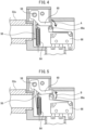
FIG. 4 is a partially cut-away side view of the swing-type water flow detector ofFIG. 3 when the opening/closing member is in the closed position. -
FIG. 5 is a partially cut-away side view of the swing-type water flow detector ofFIG. 3 when the opening/closing member is in the open position. - The preferred embodiments of the present invention will be described below with reference to the attached drawings.
- In
FIG. 1 , awater supply device 100 comprises awater supply conduit 102 for circulating tap water as raw water, amineral source 104 connected to atube pump 10 via a mineralliquid supply conduit 106, and adetector 108 for detecting whether or not water is flowing through thewater supply conduit 102. Themineral source 104 can be, for example, a pouch-like container as a holding part for holding a concentrated liquid (mineral liquid) containing potassium chloride or a mineral component similar to potassium chloride, which are examples of the additive liquid. - Referring to
FIG. 2 , thetube pump 10 comprises ahousing 12 defining apump chamber 14, and a rotor assembly disposed within thepump chamber 14. Thepump chamber 14 has an inner peripheral surface extending circumferentially about the center O. The mineralliquid supply conduit 106 is located partially within thepump chamber 14. The mineralliquid supply conduit 106 is flexible at least in the portion located inside thepump chamber 14. In thepump chamber 14, the mineralliquid supply conduit 106 extends along the inner peripheral surface of thepump chamber 14. - The rotor assembly is arranged in the
pump chamber 14 so as to be rotatable about the center O. The rotor assembly comprises acarrier 16 which is rotatable about the center O. Thecarrier 16 has arotating shaft 18 extending along an axis passing through the center O perpendicular to the paper surface ofFIG. 2 . Thecarrier 16 has a plurality of arms, four in the example ofFIG. 2 , arranged at equal angular intervals relative to the center O, and arotor 20 is attached to the tip of each arm. Eachrotor 20 is attached to the tip of each arm so as to be rotatable around a rotating shaft 22 extending parallel to the rotatingshaft 18. - The portion of the mineral
liquid supply conduit 106 located within thepump chamber 14 is pressed against the inner peripheral surface of thepump chamber 14 by eachrotor 20 and partially deformed. The shape (the number of arms) and dimensions of thecarrier 16 and the dimensions of therotor 20 can be appropriately determined in consideration of the flow rate of the mineral liquid to be added. - The
tube pump 10 further comprises a drive motor 24 (FIG. 1 ) coupled to the rotatingshaft 18. Thedrive motor 24 is preferably powered by replaceable batteries (not illustrated) or rechargeable batteries (not illustrated). When thedetector 108 detects that water is flowing through thewater supply conduit 102, thedrive motor 24 is supplied with power from a power source (not illustrated) and driven to rotate. The number of revolutions of thedrive motor 24 at this time can be appropriately determined in consideration of the flow rate of the mineral liquid to be added. - When the
drive motor 24 rotates, thecarrier 16 also rotates about the center O as indicated by arrow A. As a result, the portion of the mineralliquid supply conduit 106 pressed and deformed by therotor 20 also moves in the direction of arrow A about the center O along the inner peripheral surface of thepump chamber 14. As a result, the mineral liquid is supplied from themineral source 104 to thewater supply conduit 102 through the mineralliquid supply conduit 106, as indicated by arrow FM. - Referring to
FIG. 3 , a swing-type water flow detector 50 using a rotating opening/closing member is shown as an example ofdetector 108. The water flow detector 50 is disposed between aninlet conduit 52a andoutlet conduit 52b forming thewater supply conduit 102. The water flow detector 50 comprises, as primary constituent elements, an opening/closing member 56, a rotatingshaft 58, aswing arm 60, amicro switch 66, and ahollow housing 54 which surrounds and houses the opening/closing member 56, the rotatingshaft 58, and theswing arm 60. - The
inlet conduit 52a and theoutlet conduit 52b are coupled to thehousing 54 so as to communicate within thehousing 54. In the illustrated embodiment, theinlet conduit 52a and theoutlet conduit 52b are perpendicular to each other, but the invention is not limited thereto, and they may be coupled tohousing 54 at other angles. - Within the
housing 54, the rotatingshaft 58 extends along an axis Os perpendicular to both theinlet conduit 52a and theoutlet conduit 52b. The rotatingshaft 58 is attached to thehousing 54 so as to be rotatable about the axis Os. - The opening/
closing member 56 is coupled to the rotatingshaft 58 so as to be capable of rotating therewith. The opening/closing member 56 is composed of a plate-like member which is capable of closing theinlet conduit 52a. The opening/closing member 56 is movable between a closed position and an open position by rotating about the axis Os. In the closed position, the opening/closing member 56 abuts the end surface of theinlet conduit 52a opening into thehousing 54, and in the open position, the opening/closing member 56 is separated from the end surface of theinlet conduit 52a. - The
swing arm 60 is also coupled to the rotatingshaft 58 so as to be capable of rotating with the rotatingshaft 58. Theswing arm 60 is connected at one end to the rotatingshaft 58 and extends vertically from the rotatingshaft 58 in the manner of a cantilever beam. Themicro switch 66 having anactuator 66a is arranged near the tip of theswing arm 60. In themicro switch 66, when force is applied to theactuator 66a in the downward direction ofFIG. 3 , this force is transmitted to the contacts of themicro switch 66, themicro switch 66 is closed (ON), and when the force applied to theactuator 66a is released, themicro switch 66 is opened (OFF). The opening/closing (ON/OFF) of themicro switch 66 may be reversed. - The
micro switch 66 is positioned within thehousing 54 relative to theswing arm 60 such that when the opening/closing member 56 is in the closed position, theswing arm 60 presses theactuator 66a to close (ON) themicro switch 66, and when the opening/closing member 56 is in the open position, theswing arm 60 is spaced from theactuator 66a and themicro switch 66 is opened (OFF). - If the weight of the opening/
closing member 56 and theswing arm 60 prevents theswing arm 60 from fully pressing theactuator 66a of themicro switch 66, a biasing member may be provided to bias theswing arm 60 toward theactuator 66a. In the present embodiment, the biasing member comprises ahelical spring 64. InFIG. 3 , thehelical spring 64 is arranged on the lower side of theswing arm 60, i.e., on the micro switch side, and is connected to theswing arm 60 at one end (the upper end inFIG. 3 ), and the other end (the lower end inFIG. 3 ) is connected to abracket 62 which is affixed to the inner wall of theoutlet conduit 52b. Thus, the tip of theswing arm 60 is always biased toward theactuator 66a of themicro switch 66. - The mode of operation of the present embodiment will be described below.
- When water is not flowing through the
water supply conduit 102, in particular, theinlet conduit 52a, the weight of therotating shaft 58 andswing arm 60 and/or the elastic force of thehelical spring 64 positions the opening/closingmember 56 in the closed position as shown inFIGS. 3 and4 . At this time, theactuator 66a is pressed by theswing arm 60, and themicro switch 66 is closed (ON). As a result, it is detected that no water is flowing through thewater supply conduit 102, the power supply to thedrive motor 24 is cut off, and thetube pump 10 is stopped. - When water flows through the
water supply conduit 102, in particular, theinlet conduit 52a, toward thehousing 54, the water pressure causes the opening/closingmember 56 to move away from the end surface of theinlet conduit 52a against the weight of therotating shaft 58 andswing arm 60 and/or the elastic force of thehelical spring 64, as shown inFIG. 5 . Specifically, the opening/closingmember 56 moves from the closed position to the open position. As a result, theswing arm 60 rotates upward about the axis Os together with the rotatingshaft 58, counterclockwise inFIG. 3 (the direction indicated by arrow B), i.e., in the direction away from themicro switch 66. Thus, when theswing arm 60 separates from theactuator 66a, themicro switch 66 is opened (OFF). As a result, it is detected that water is flowing through thewater supply conduit 102, power is supplied to thedrive motor 24, and thetube pump 10 operates. - When the flow of water in the
inlet conduit 52a stops, the weight of therotating shaft 58 andswing arm 60 and/or the spring force of thehelical spring 64 causes theswing arm 60 to rotate about the axis Os in the direction indicated by arrow A inFIG. 4 . Thus, theactuator 66a of themicro switch 66 is pushed toward the body of themicro switch 66 by theswing arm 60. As a result, themicro switch 66 is closed (ON), it is detected that water is not flowing through thewater supply conduit 102 as described above, the power supply to thedrive motor 24 is cut off, and thetube pump 10 is stopped. - The spring constant and length of the
helical spring 64, the inner diameter of theinlet conduit 52a, and the length of theswing arm 60 can be determined considering the flow rate and pressure of the water flowing through theinlet conduit 52a, as well as the force of theactuator 66a of themicro switch 66 pushing up theswing arm 60 so that theswing arm 60 presses and pushes down theactuator 66a when water is not flowing through theinlet conduit 52a, and theswing arm 60 can be separated from theactuator 66a when water is flowing through theinlet conduit 52a. - Though the
detector 108 is a swing water flow detector 50 in the embodiment described above, a water flow detector having an impeller and a generator driven by the impeller, or a flow meter which measures flow rate based on differential pressure may be used. - The water supply device of the present invention can be incorporated into any drinking water supply system for providing drinking water, such as water servers and water purifiers. Even in such a case, since the water supply device of the present invention has a simple structure, the size of the installation area of the entire device can be reduced.
-
- 10
- Tube Pump
- 12
- Housing
- 14
- Pump Chamber
- 16
- Carrier
- 18
- Rotating shaft
- 20
- Rotor
- 22
- Rotating shaft
- 24
- Drive Motor
- 50
- Water Flow Detector
- 52a
- Inlet Conduit
- 52b
- Outlet Conduit
- 54
- Housing
- 56
- Opening/Closing Member
- 58
- Rotating shaft
- 60
- Swing Arm
- 62
- Bracket
- 66
- Micro Switch
- 66a
- Actuator
- 100
- Water Supply Device
- 102
- Water Supply Conduit
- 104
- Holding Part
- 104
- Mineral Source
- 106
- Mineral Liquid Supply Conduit
- 108
- Detector
Claims (5)
- A water supply device, comprising:an additive liquid holding part,a water flow path to which the additive liquid is added, andan additive liquid supply means, the water supply device further comprising:
a detector which detects water flow in the flow path, wherein when the detector detects water flow, the additive liquid is added from the supply means. - The water supply device according to claim 1, wherein the detector comprises an opening/closing member which opens or closes depending on water flow in the water flow path.
- The water supply device according to claim 1 or 2, wherein the additive liquid supply means is a tube pump.
- The water supply device according to claim 3, wherein the tube pump comprises a housing defining a pump chamber having a circumferentially extending inner peripheral surface, and a rotor assembly which is disposed within the pump chamber so as to be capable of rotating, and
a mineral liquid supply conduit extends along the inner peripheral surface of the pump chamber, the mineral liquid supply conduit is pressed and at least partially deformed against the inner peripheral surface of the pump chamber by the rotor assembly, and when the rotor assembly rotates, a portion which is deformed by the rotor assembly moves along the inner peripheral surface of the pump chamber so as to push out mineral liquid in the mineral liquid supply conduit. - A drinking water supply system, comprising the water supply device according to any one of claims 1 to 4.
Applications Claiming Priority (2)
| Application Number | Priority Date | Filing Date | Title |
|---|---|---|---|
| JP2020219551A JP2022104374A (en) | 2020-12-28 | 2020-12-28 | Water supply device |
| PCT/JP2021/049001 WO2022145485A1 (en) | 2020-12-28 | 2021-12-28 | Water supply device |
Publications (2)
| Publication Number | Publication Date |
|---|---|
| EP4269326A1 true EP4269326A1 (en) | 2023-11-01 |
| EP4269326A4 EP4269326A4 (en) | 2024-06-12 |
Family
ID=82260832
Family Applications (1)
| Application Number | Title | Priority Date | Filing Date |
|---|---|---|---|
| EP21915343.4A Pending EP4269326A4 (en) | 2020-12-28 | 2021-12-28 | Water supply device |
Country Status (9)
| Country | Link |
|---|---|
| US (1) | US20240068208A1 (en) |
| EP (1) | EP4269326A4 (en) |
| JP (1) | JP2022104374A (en) |
| KR (1) | KR20230104290A (en) |
| CN (1) | CN116710390A (en) |
| AU (1) | AU2021412682B2 (en) |
| CA (1) | CA3205087A1 (en) |
| IL (1) | IL304061A (en) |
| WO (1) | WO2022145485A1 (en) |
Families Citing this family (1)
| Publication number | Priority date | Publication date | Assignee | Title |
|---|---|---|---|---|
| CN119750741A (en) * | 2025-01-09 | 2025-04-04 | 扬州玖月玖工程科技有限公司 | An intelligent dosing control system and method for water affairs |
Family Cites Families (16)
| Publication number | Priority date | Publication date | Assignee | Title |
|---|---|---|---|---|
| US4955507A (en) * | 1980-10-29 | 1990-09-11 | The Coca-Cola Company | Orange juice dispensing system |
| US5000351A (en) * | 1986-03-21 | 1991-03-19 | The Coca-Cola Company | Concentrate dispensing system for a post-mix beverage dispenser |
| JPH07241555A (en) * | 1994-03-07 | 1995-09-19 | Mitsubishi Rayon Co Ltd | Water purifier |
| JPH0871571A (en) * | 1994-09-09 | 1996-03-19 | Tec Corp | Water generator |
| JP2002119968A (en) * | 2000-10-13 | 2002-04-23 | Sanden Corp | Mineral water production equipment |
| JP2002282872A (en) * | 2001-03-27 | 2002-10-02 | Matsushita Electric Works Ltd | Water treatment equipment |
| JP2003010661A (en) * | 2001-06-29 | 2003-01-14 | Mitsubishi Rayon Eng Co Ltd | Carbonated water production device and method of operating carbonated water production device |
| JP2005256812A (en) * | 2004-03-15 | 2005-09-22 | Ckd Corp | Tube pump |
| US20050258082A1 (en) | 2004-05-24 | 2005-11-24 | Lund Mark T | Additive dispensing system and water filtration system |
| GB2425523A (en) * | 2005-04-28 | 2006-11-01 | Senake Atureliya | Depositing doses of a fluid |
| JP2013151912A (en) * | 2012-01-25 | 2013-08-08 | Mimaki Engineering Co Ltd | Tube pump and inkjet printer |
| ITTO20120930A1 (en) * | 2012-10-23 | 2014-04-24 | Bruno Pirone | ADDITIVATION DEVICE FOR DRINKS AND ASSOCIATED METHOD. |
| CN109199120B (en) * | 2017-06-30 | 2021-07-30 | 佛山市顺德区美的电热电器制造有限公司 | Water inlet detection device, cooking utensil and water inlet detection method |
| JP2020028827A (en) * | 2018-08-21 | 2020-02-27 | 夕子 木村 | DRINKING WATER PRODUCING APPARATUS AND METHOD OF PRODUCING DRINKING WATER USING THE SA |
| KR102594512B1 (en) * | 2018-11-15 | 2023-10-25 | 엘지전자 주식회사 | Washing machine |
| EP4061766A1 (en) * | 2019-11-20 | 2022-09-28 | Sum LLC | Beverage apparatus and method |
-
2020
- 2020-12-28 JP JP2020219551A patent/JP2022104374A/en active Pending
-
2021
- 2021-12-28 KR KR1020237020495A patent/KR20230104290A/en not_active Ceased
- 2021-12-28 IL IL304061A patent/IL304061A/en unknown
- 2021-12-28 CN CN202180087858.4A patent/CN116710390A/en active Pending
- 2021-12-28 CA CA3205087A patent/CA3205087A1/en active Pending
- 2021-12-28 WO PCT/JP2021/049001 patent/WO2022145485A1/en not_active Ceased
- 2021-12-28 US US18/269,805 patent/US20240068208A1/en not_active Abandoned
- 2021-12-28 AU AU2021412682A patent/AU2021412682B2/en active Active
- 2021-12-28 EP EP21915343.4A patent/EP4269326A4/en active Pending
Also Published As
| Publication number | Publication date |
|---|---|
| EP4269326A4 (en) | 2024-06-12 |
| AU2021412682A1 (en) | 2023-07-06 |
| AU2021412682B2 (en) | 2025-05-08 |
| KR20230104290A (en) | 2023-07-07 |
| WO2022145485A1 (en) | 2022-07-07 |
| US20240068208A1 (en) | 2024-02-29 |
| IL304061A (en) | 2023-08-01 |
| JP2022104374A (en) | 2022-07-08 |
| CA3205087A1 (en) | 2022-07-07 |
| AU2021412682A9 (en) | 2024-10-24 |
| CN116710390A (en) | 2023-09-05 |
Similar Documents
| Publication | Publication Date | Title |
|---|---|---|
| JP4995569B2 (en) | Compact liquid processing system with built-in power supply | |
| US20240068208A1 (en) | Water supply device | |
| CA2707477C (en) | Low power electric operated thermostatic mixing valve | |
| EP3171027A2 (en) | Tube pump | |
| US9057632B2 (en) | Apparatus and method for measuring flow rate of meter | |
| US6082703A (en) | Hydraulic valve controlled by a photoelectric cell and operated by an electric motor | |
| CN101523051B (en) | Fluid system with pump activation device | |
| US4963857A (en) | Translatable dual magnets | |
| JP6007283B1 (en) | Flow rate detector | |
| EP0842361A1 (en) | Circulator pump check valve | |
| WO2008026537A1 (en) | Power generator for faucet | |
| JP4394588B2 (en) | Roller infusion pump | |
| CN219013383U (en) | Regulating butterfly valve | |
| CN219328014U (en) | Leak preventer | |
| JP5146900B2 (en) | Generator and faucet device | |
| JP2008050852A (en) | Water faucet fitting | |
| CN208900423U (en) | A kind of impeller inducer | |
| CA1185484A (en) | Constant delivery inertia pump | |
| JP4389905B2 (en) | Fluid control valve | |
| WO2005005871A1 (en) | Float valve type liquid flow control regulator | |
| SU1388762A1 (en) | Device for imparting wear by abrasive particles | |
| JP2023121113A (en) | Water meter unit and water meter unit control system | |
| JP2020097944A (en) | Fluid control valve and shutoff device using the same | |
| JP4389904B2 (en) | Fluid control valve | |
| JP2007274858A (en) | Generator for faucet, and automatic faucet device with generator |
Legal Events
| Date | Code | Title | Description |
|---|---|---|---|
| STAA | Information on the status of an ep patent application or granted ep patent |
Free format text: STATUS: THE INTERNATIONAL PUBLICATION HAS BEEN MADE |
|
| PUAI | Public reference made under article 153(3) epc to a published international application that has entered the european phase |
Free format text: ORIGINAL CODE: 0009012 |
|
| STAA | Information on the status of an ep patent application or granted ep patent |
Free format text: STATUS: REQUEST FOR EXAMINATION WAS MADE |
|
| 17P | Request for examination filed |
Effective date: 20230606 |
|
| AK | Designated contracting states |
Kind code of ref document: A1 Designated state(s): AL AT BE BG CH CY CZ DE DK EE ES FI FR GB GR HR HU IE IS IT LI LT LU LV MC MK MT NL NO PL PT RO RS SE SI SK SM TR |
|
| DAV | Request for validation of the european patent (deleted) | ||
| DAX | Request for extension of the european patent (deleted) | ||
| A4 | Supplementary search report drawn up and despatched |
Effective date: 20240513 |
|
| RIC1 | Information provided on ipc code assigned before grant |
Ipc: F04C 5/00 20060101ALI20240506BHEP Ipc: F04B 43/12 20060101ALI20240506BHEP Ipc: C02F 1/68 20060101ALI20240506BHEP Ipc: B67D 1/10 20060101AFI20240506BHEP |