EP4269234A1 - Skewed roller impeller cage for use with a rotary no-back device - Google Patents
Skewed roller impeller cage for use with a rotary no-back device Download PDFInfo
- Publication number
- EP4269234A1 EP4269234A1 EP23169750.9A EP23169750A EP4269234A1 EP 4269234 A1 EP4269234 A1 EP 4269234A1 EP 23169750 A EP23169750 A EP 23169750A EP 4269234 A1 EP4269234 A1 EP 4269234A1
- Authority
- EP
- European Patent Office
- Prior art keywords
- skewed
- disc
- flow channels
- roller assembly
- impeller flow
- Prior art date
- Legal status (The legal status is an assumption and is not a legal conclusion. Google has not performed a legal analysis and makes no representation as to the accuracy of the status listed.)
- Pending
Links
Images




Classifications
-
- B—PERFORMING OPERATIONS; TRANSPORTING
- B64—AIRCRAFT; AVIATION; COSMONAUTICS
- B64C—AEROPLANES; HELICOPTERS
- B64C13/00—Control systems or transmitting systems for actuating flying-control surfaces, lift-increasing flaps, air brakes, or spoilers
- B64C13/24—Transmitting means
-
- F—MECHANICAL ENGINEERING; LIGHTING; HEATING; WEAPONS; BLASTING
- F16—ENGINEERING ELEMENTS AND UNITS; GENERAL MEASURES FOR PRODUCING AND MAINTAINING EFFECTIVE FUNCTIONING OF MACHINES OR INSTALLATIONS; THERMAL INSULATION IN GENERAL
- F16D—COUPLINGS FOR TRANSMITTING ROTATION; CLUTCHES; BRAKES
- F16D65/00—Parts or details
- F16D65/78—Features relating to cooling
-
- F—MECHANICAL ENGINEERING; LIGHTING; HEATING; WEAPONS; BLASTING
- F16—ENGINEERING ELEMENTS AND UNITS; GENERAL MEASURES FOR PRODUCING AND MAINTAINING EFFECTIVE FUNCTIONING OF MACHINES OR INSTALLATIONS; THERMAL INSULATION IN GENERAL
- F16D—COUPLINGS FOR TRANSMITTING ROTATION; CLUTCHES; BRAKES
- F16D59/00—Self-acting brakes, e.g. coming into operation at a predetermined speed
-
- F—MECHANICAL ENGINEERING; LIGHTING; HEATING; WEAPONS; BLASTING
- F16—ENGINEERING ELEMENTS AND UNITS; GENERAL MEASURES FOR PRODUCING AND MAINTAINING EFFECTIVE FUNCTIONING OF MACHINES OR INSTALLATIONS; THERMAL INSULATION IN GENERAL
- F16D—COUPLINGS FOR TRANSMITTING ROTATION; CLUTCHES; BRAKES
- F16D63/00—Brakes not otherwise provided for; Brakes combining more than one of the types of groups F16D49/00 - F16D61/00
-
- F—MECHANICAL ENGINEERING; LIGHTING; HEATING; WEAPONS; BLASTING
- F16—ENGINEERING ELEMENTS AND UNITS; GENERAL MEASURES FOR PRODUCING AND MAINTAINING EFFECTIVE FUNCTIONING OF MACHINES OR INSTALLATIONS; THERMAL INSULATION IN GENERAL
- F16D—COUPLINGS FOR TRANSMITTING ROTATION; CLUTCHES; BRAKES
- F16D65/00—Parts or details
- F16D65/02—Braking members; Mounting thereof
- F16D65/028—Rollers
-
- B—PERFORMING OPERATIONS; TRANSPORTING
- B64—AIRCRAFT; AVIATION; COSMONAUTICS
- B64C—AEROPLANES; HELICOPTERS
- B64C13/00—Control systems or transmitting systems for actuating flying-control surfaces, lift-increasing flaps, air brakes, or spoilers
- B64C13/24—Transmitting means
- B64C13/38—Transmitting means with power amplification
-
- F—MECHANICAL ENGINEERING; LIGHTING; HEATING; WEAPONS; BLASTING
- F16—ENGINEERING ELEMENTS AND UNITS; GENERAL MEASURES FOR PRODUCING AND MAINTAINING EFFECTIVE FUNCTIONING OF MACHINES OR INSTALLATIONS; THERMAL INSULATION IN GENERAL
- F16D—COUPLINGS FOR TRANSMITTING ROTATION; CLUTCHES; BRAKES
- F16D65/00—Parts or details
- F16D65/02—Braking members; Mounting thereof
- F16D2065/022—Rollers
-
- F—MECHANICAL ENGINEERING; LIGHTING; HEATING; WEAPONS; BLASTING
- F16—ENGINEERING ELEMENTS AND UNITS; GENERAL MEASURES FOR PRODUCING AND MAINTAINING EFFECTIVE FUNCTIONING OF MACHINES OR INSTALLATIONS; THERMAL INSULATION IN GENERAL
- F16D—COUPLINGS FOR TRANSMITTING ROTATION; CLUTCHES; BRAKES
- F16D65/00—Parts or details
- F16D65/78—Features relating to cooling
- F16D2065/788—Internal cooling channels
-
- F—MECHANICAL ENGINEERING; LIGHTING; HEATING; WEAPONS; BLASTING
- F16—ENGINEERING ELEMENTS AND UNITS; GENERAL MEASURES FOR PRODUCING AND MAINTAINING EFFECTIVE FUNCTIONING OF MACHINES OR INSTALLATIONS; THERMAL INSULATION IN GENERAL
- F16D—COUPLINGS FOR TRANSMITTING ROTATION; CLUTCHES; BRAKES
- F16D41/00—Freewheels or freewheel clutches
- F16D41/06—Freewheels or freewheel clutches with intermediate wedging coupling members between an inner and an outer surface
- F16D41/064—Freewheels or freewheel clutches with intermediate wedging coupling members between an inner and an outer surface the intermediate members wedging by rolling and having a circular cross-section, e.g. balls
Definitions
- the present disclosure relates generally to a skewed-roller brake assembly, and more particularly, to a skewed-roller cage design with improved lubricating oil circulation.
- the maneuverability of an aircraft depends heavily on the movement of hinged sections or flaps located at the trailing edges of the wings.
- the aerodynamic flow conditions of the wings may be influenced so as to increase or decrease the lift generated by the wings.
- the position of the flaps of the aircraft are adjusted to optimize the lift and drag characteristics of the wing. It can be appreciated the reliable operation of the flaps is of importance to an aircraft.
- the flap control lever is connected by conventional and/or teleflex cables to a hydraulic actuating mechanism, which is commonly driven by a motor system.
- the flap actuator includes a shaft extending along a longitudinal axis and having a terminal end operatively connectable to the flap. The shaft is movable between a first retracted position and a second extended position.
- a no-back brake assembly is operatively connectable to the shaft.
- the no-back brake assembly can prevent movement of the shaft toward the retracted position in response to a compressive force generated by the flap.
- a skewed roller is one type of no-back brake. Skewed roller brakes develop friction between a pair of rotating axially loaded discs by rollers carried in a slotted cage. The axis of the slots in the cage are skewed or angled relative to a radial line from a center of rotation or rotational axis of the cage. As the rollers roll between the discs, they tend to provide sliding frictional resistance parallel to the rotational movement of the two discs.
- Skewed-rollers may be partially submerged in a lubricating oil to dissipate heat generated by the friction.
- the present disclosure addresses improvements in dissipating the heat generated.
- the present disclosure relates to a skewed roller assembly.
- the skewed roller assembly can include a disc formed as a thin metallic ring.
- the disc can have a first side and an opposite second side. In certain examples, the first side is a top side and the second side is a bottom side.
- the disc includes an inner diameter and an outer diameter. The disc is designed to be positioned against a flange on an actuator drive shaft.
- the disc can include rectangular slots arranged radially in which rollers of a no-back device are positioned.
- the slots are defined through the disc and are skewed at a specified angle to generate a specific amount of friction which can be determined by the subjected axial load and speed of the actuator.
- Impeller shaped channels are arranged on the first and second sides of the disc to force fluid to circulate from the outer diameter of the disc to the inner diameter of the disc when the disc is rotated in a first direction.
- the impeller shaped channels on the second side of the disc are in a reverse orientation to the impeller shaped channels on the first side of the disc.
- the impeller shaped channels on the second side of the disc force fluid to circulate from the inner diameter of the disc to the outer diameter of the disc when the disc is rotated in a second direction.
- Cutouts may be defined at the inner diameter of the disc. In other examples, the cutouts may be defined on an outer diameter of the shaft of the actuator, although alternatives are possible.
- the cutouts can be positioned adjacent to the first and second plurality of impeller flow channels to scoop fluid for continuous circulation around the disc.
- the fluid flows in the impeller shaped channels and centrifugal forces move the fluid from the top side to the bottom side or vice versa.
- the continuous circulation of fluid lubricates the rollers to improve heat dissipation in the system.
- a rotary no-back device may be integrated within an aircraft flight control actuation system, such a flap and/or slat system. There may be other applications the no-back device may be integrated with, including but not limited to, fuel doors.
- the no-back capability of the rotary no-back device will prevent an aircraft flight control surface from being displaced from a desired position if a failure occurs to the actuation system's drive line.
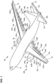
- the aircraft 10 includes a fuselage 12, left and right wings 14, 16, a vertical stabilizer 18, and left and right horizontal stabilizers 20, 22.
- the aircraft 10 is also provided with a number of primary flight control surfaces for operating the aircraft 10 during flight. Examples of such primary flight control surfaces are ailerons 14a, 14b and spoilers 16a, 16b associated with the left and right wings 14, 16, a rudder 18a associated with the vertical stabilizer 18, and elevators 20a, 22a associated with the left and right horizontal stabilizers 20, 22.
- the aircraft 10 is also shown as being provided with jet engines 24, 26 respectively associated with the left and right wings 14, 16.
- the aircraft 10 is also provided with a number of secondary control surfaces 100 which are generally used during take-off and landing procedures.
- secondary control surfaces 100 are slats 102 (102a - 102d) and flaps 106 (106a - 106c) associated with the left wing 14, slats 104 (104a - 104d) and flaps 108 (108a - 108c) associated with the right wing 16, and thrust reversers 110 (110a, 110b), 112 (112a, 112b) respectively associated with the left and right engines 24, 26.
- the slats 102, 104 and flaps 106, 108 can be extended during takeoff to increase the overall size and lift of the wings 14, 16. In the extended position, the slats 102, 104 and flaps 106, 108 greatly increase the lift generated by the wings 14, 16, which in turn enables the aircraft 10 to take off more capably and under heavier loads. When takeoff is complete and the aircraft 10 enters a cruising phase, the slats 102, 104 and flaps 106, 108 can be retracted to reduce drag on the wings 14, 16 and therefore allow for more efficient operation.
- the slats 102, 104 and/or flaps 106, 108 can also be used during the landing procedure to reduce the required distance and speed to safely land the aircraft 10.
- the slats 102, 104 and flaps 106, 108 can be characterized as being high-lift devices.
- thrust reversers 110, 112 can be activated into an extended position to temporarily divert the thrust of the engines 24, 26. By activating the thrust reversers 110, 112, the diverted thrust acts against the forward direction of the aircraft 10 to provide deceleration just after touchdown such that the diverted thrust acts against the forward travel of the aircraft.
- the incorporation of thrust reversers 110, 112 therefore enables the aircraft 10 to land over a shorter distance and reduces the wear on the brakes of the aircraft 10.
- the thrust reversers 110, 112 can be characterized as forming part of a thrust reverser actuation system (TRAS).
- TAS thrust reverser actuation system
- an example rotary device assembly 200 is illustrated in accordance with principles of the present disclosure.
- the rotary device assembly 200 may be configured as a brake to transmit force which restricts rotation of a member.
- the rotary device assembly 200 can relate generally to aircrafts, and in particular, to controlling the above-described primary and secondary control surfaces of the aircraft 10.
- the rotary device assembly 200 may be used in a wide variety of applications.
- the rotary device assembly 200 may include a nonrotatable brake member 202, two roller bearing assemblies 204 disposed at least partially between a rotating member 206 (e.g., a ball screw, a shaft, etc.) and a stationary member 208 (e.g., a housing). It will be appreciated that the rotary device assembly 200 may have a different construction. For example, the rotary device assembly 200 may include a single skewed roller assembly 204. It will be appreciated that the two roller bearing assemblies 204 can have the same construction and mode of operation. As such, only one skewed roller assembly 204 will be described in detail.
- the aircraft 10 may utilize the rotary device assembly 200 for controlling various aircraft flight surfaces.
- the slats 102 (102a - 102d) and flaps 106 (106a - 106c) associated with the left wing 14 and the slats 104 (104a - 104d) and flaps 108 (108a - 108c) associated with the right wing 16 can be pivoted by the rotary device assembly 200 provided in flap actuators or slat actuators of the aircraft 10.
- the rotary device assembly 200 can be operably coupled to the left and right wings 14, 16 of the aircraft 10 and to an associated one or more of the slats/flaps 102, 104, 106, 108 to execute the pivoting actions thereof.
- the rotary device assembly 200 is configured to transmit a torque from the rotating member 206 which is rotatable relative to the nonrotatable brake member 202.
- the rotary device assembly 200 can control pivoting of the slat/flap control surfaces with no-back capability. That is, the rotary device assembly 200 can prevent a loss of position control of the primary or secondary control surfaces by grounding the resultant torque to a structural ground to thereby lock the primary or secondary control surfaces in a fixed position.
- the rotary device assembly 200 can be used to prevent loss of position control of the slats/flaps 102, 104, 106, 108 by grounding the resultant torque to thereby lock the slats/flaps 102, 104, 106, 108 in a fixed position.
- a signal can be sent from a main system processor to a control surface actuation system usable to operate control surfaces of the aircraft 10, including but not limited to, the above-described primary and secondary control surfaces.
- the control surface can be driven by an actuator or multiple actuators. In some examples, a single actuator can be used to drive multiple control surfaces.
- the actuator can be used to drive a control surface by operating a member operably connected to the control surface.
- the actuator can be, for example, a linear acting actuator with a linear screw driven by a motor.
- the member is operably connected to an actuator via a gear set, such as a planetary gear set.
- the member is a part of an actuator, such as a shaft of an actuator.
- a position sensor can be provided on an actuator for use in feedback control of the motor.
- the control surface can correspond to any of the control surfaces 14a/b, 16a/b, 18a, 20a, 22a, 102, 104, 106, 108 shown in FIG. 1 .
- the rotating member 206 may be connected with a horizontal stabilizer on the aircraft 10.
- the rotating member 206 may extend along the longitudinal central axis 210 and have a terminal end operatively connectable to the flaps and/or slats.
- the roller bearing assemblies 204 may facilitate rotation of the rotating member 206 relative to the nonrotatable brake member 202.
- the rotating member 206 is rotatable about its longitudinal central axis 210 while the stationary member 208 is held against rotation about the longitudinal central axis 210.
- the rotating member 206 has an annular flange 212 which is enclosed by the stationary member 208.
- the rotating member 206 and thus the flaps and/or slats of the aircraft 10 may be movable between a first retracted position and a second extended position.
- the no-back capability of the rotary device assembly 200 prevents movement of the rotating member 206 toward the retracted position in response to a compressive force generated by the flaps and/or slats.
- the flange 212 may be pulled toward a respective one of the two roller bearing assemblies 204. If the actuator extends as a result of pulling forces imparted to it by the flaps and/or slats, the no-back assembly is configured to resist that back driving force so it is not felt by the actuator. That is, if the flap applies a compressive force on the actuator, the actuator will not feel the external compressive force applied to it due to the no-back assembly designed to resist the back driving forces allowing the actuator to retract when driven to retract or extend when driven to extend.
- the skewed roller assembly 204 may include a circular or annular disc 214 (e.g., retainer member) with an annular array of spaced apart skewed-roller slots 216.
- the skewed-roller slots 216 may be formed through the disc 214.
- the circular or annular disc 214 may include one or more of a variety of shapes, sizes, configurations, and/or materials.
- the disc 214 may be a thin metallic ring that can be positioned against the flange 212.
- the disc 214 may comprise a brass material, although alternatives are possible.
- the disc 214 may comprise a hardened steel, although alternatives are possible.
- the disc 214 may be machined or printed using an additive manufacturing process, although alternatives are possible.
- the skewed-roller slots 216 may be rectangular slots that each extend generally in a radial direction. In certain examples, the skewed-roller slots 216 may be machined slots preferably evenly spaced around the disc 214. It will be appreciated that the skewed-roller slots 216 may be formed using a variety of processes. Each of the skewed-roller slots 216 may have a longitudinal central axis 218 that is skewed at an angle ⁇ relative to a disc radius 220 (i.e., central axis) that extends through a center 222 of the skewed-roller slot 216. That is, the skewed-roller slots 216 are skewed by an angle ⁇ relative to a radial line from the center 220 of the disc 214.
- the skewed-roller slots 216 may be skewed at a specific angle to generate a desired amount of friction.
- the amount of friction can be determined by a subjected axial load and speed of an actuator drive shaft.
- the skewing angle ⁇ may be within the range of about 0 degrees to about 90 degrees. In certain examples, the skewing angle ⁇ may be within the range of about 30 degrees to about 60 degrees. In another example, the skewing angle ⁇ may be about 45 degrees. It will be appreciated that the skewing angle ⁇ may be optimized to provide a desired performance characteristics including, for example, friction and/or heat dissipation.
- a respective roller 224 may be disposed in each of the skewed-roller slots 216.
- the skewed-roller slots 216 may be used for guiding and spacing the rollers 224.
- the rollers 224 may be rotatably mounted in an annular array on the annular disc 214 a distance from the center of rotation 220 of the disc 214.
- the rollers 224 are rotatable in the skewed-roller slots 216 about their respective axis 218.
- the rollers 224 are effective to transmit force between a plate 225 (see FIG. 2 ) connected with the flange 212 and the stationary member 208.
- the rollers 224 When in use, the rollers 224 can be subject to high thrust loads and torques, resulting in high rotational speeds of the disc 214 and high friction on the roller surfaces which increases the temperature at the friction points. That is, friction may be transformed into and/or result in heat, and the amount of heat may correspond to a combination of thrust force, the coefficient of friction (COF), the friction radius R, and the spinning velocity of the disc 214, which may correspond, for example, to the spinning velocity of the rotating member 206. In some applications, it may be desirable to balance the heat dissipation of rollers such that they dissipate comparable, similar, and/or substantially the same amount of heat, independent of the friction radii R of the rollers.
- skewed rollers are partially submerged in a lubricating oil to help dissipate any heat generated in the system.
- a lubricating oil may be carried away by centrifugal forces from an inner diameter of the disc/cage.
- centrifugal forces carry the lubricating oil away from the friction surfaces of the rollers. Without the lubricating oil, the friction surfaces are left without lubrication and a means of dissipating the heat generated which may cause the friction surfaces to overheat and cause a no-back system to fail.
- An advantageous feature of the skewed roller assembly 204 configured according to the present disclosure is the ability to manage the direction of fluid flow in the system by forcing fluid (e.g., lubricating oil, etc.) to circulate around the disc 214 continuously to lubricate the rollers 224 in the skewed roller slots 216 and improve heat dissipation from the friction points.
- fluid e.g., lubricating oil, etc.
- FIGS. 10-11 show a perspective view of the skewed roller assembly 204.
- the disc 214 includes a plurality of impeller flow channels 226 (e.g., slots) defined by impeller shaped structures 228 arranged on a first side 230 (e.g., top side, high pressure side) of the disc 214. That is, the plurality of impeller flow channels 226 are formed across a surface of the first side 230 from an outer periphery or outer diameter OD of the disc 214 to an inner periphery or inner diameter ID of the disc 214.
- the plurality of impeller flow channels 226 are arranged in an annular array on the first side 230 of the disc 214 to force lubricating oil between the outer and inner peripheries.
- the lubricating oil is forced to circulate from the outer diameter OD (see FIG. 12 ) of the disc 214 to the inner diameter ID (see FIG. 12 ) of the disc 214 or vice versa.
- the lubricating oil is designed to flow through the plurality of impeller flow channels 226 on the first side 230 of the disc 214 in a direction from the outer diameter OD toward the inner diameter ID.
- each roller 224 extends across a respective one of the impeller flow channels 226 so that lubricating fluid flowing through the impeller flow channels 226 also flows over the rollers 224.
- the center of the rollers 224 may be positioned generally in a center of the plurality of impeller flow channels 226 to allow the lubricating oil to flow over the rollers 224.
- the disc 214 further includes cutouts 232, for example semi-circular cutouts, positioned at the inner diameter ID thereof.
- the cutouts 232 allow lubricating oil to circulate between the first and second sides 230, 234 while the remaining portions of the inner diameter between the cutouts 232 allow the disc 214 to keep tight tolerances for positioning the disc 214 about the rotating member 206.
- the cutouts 232 provide flow paths past the rotating member 206 to enable the lubricating oil to pass from one side of the disc 214 to the other side of the disc 214.
- the cutouts 232 allow the lubricating oil to momentarily stay at the inner diameter ID.
- the cutouts 232 can be defined at both the entrance and exit of the plurality of impeller flow channels 226.
- FIGS. 14-17 perspective views of the disc 214 is depicted showing the second side 234 (e.g., bottom side, low pressure side) thereof.
- a plurality of impeller flow channels 226a are defined by impeller shaped structures 228a formed on the second side 234 of the disc 214.
- the plurality of impeller flow channels 226a are arranged in a reverse orientation compared to the plurality of impeller flow channels 226 on the first side 230 of the disc 214. That is, the plurality of impeller flow channels 226a can have a mirrored image to the plurality of impeller flow channels 226.
- the plurality of impeller flow channels 226, 226a are designed to scoop lubricating oil over the sides 230, 234 of the disc 214.
- the impeller flow channels 226, 226a can be provided with sidewalls 226b, 226c oriented at an oblique angle to a radius line of the disc 214 (e.g., see FIG. 15 ).
- the impeller flow channel 226, 226a has a concave shape.
- the first sidewall 226b can have a convex surface and the second sidewall 226c can have a concave surface.
- the cutouts 232 are designed to scoop and circulate the lubricating oil from the inner diameter ID of one side of the disc 214 to the opposite side and then outward to the outer diameter OD. That is, lubricating oil can exit the plurality of impeller flow channels 226 on the first side 230 of the disc 214, pass through the cutouts 232, and enter the plurality of impeller flow channels 226a formed on the second side 234 of the disc 214 to keep the lubricating oil circulating over and under the disc 214 between the first and second sides 230, 234.
- the disc 214 can rotate either in a clockwise or counterclockwise direction. As such, the lubricating oil can be pulled from either the lower pressure side 234 to the higher-pressure side 230 of the disc 214 or from the higher-pressure side 230 to the lower pressure side 234 of the disc 214.
- the plurality of impeller flow channels 226 on the first side 230 can create a high-pressure force such that the lubricating oil flows over the rollers 224 into the cutouts 232 (see FIG. 11 ).
- the plurality of impeller flow channels 226 at the first side 230 can act as an impeller, such as a centrifugal pump impeller or a Francis turbine impeller, to create a boost and thereby flow.
- the cutouts 232 are designed to scoop the lubricating oil against centrifugal forces such that the lubricating oil flows back over to the second side 234 of the disc 214 where the pressure is lower.
- the impeller flow channels 226a on the second side 234 guide the lubricant oil from the cutouts 232 to the outer diameter OD of the disc 214 when rotating in the direction D1 (see FIG. 15 ), whereby the lubricant oil can be recaptured by the impeller flow channels 226 on the first side 230.
- a skewed roller assembly (204), comprising:
- Aspect 2 The skewed roller assembly of aspect 1, wherein the plurality of impeller flow channels (226) is a first plurality; and wherein a second plurality of impeller flow channels (226s) are defined at a second side of the disc (214), the second side being opposite the first side.
- Aspect 3 The skewed roller assembly of aspect 2, wherein the fluid is a lubricating oil.
- Aspect 4 The skewed roller assembly of aspect 2 or aspect 3, wherein the impeller flow channels (226a) of the second plurality are disposed in reverse orientation to the impeller flow channels (226) of the first plurality.
- Aspect 5 The skewed roller assembly of any of aspects 1-4, wherein a plurality of cutouts (232) are defined at an inner diameter of the disc (214), each of the impeller flow channels (226) extending to a respective one of the cutouts (232).
- Aspect 6 The skewed roller assembly of any of aspects 2-4, wherein a plurality of cutouts (232) are defined at an inner diameter of the disc (214), each cutout (232) forming a path from one of the impeller flow channels (226) of the first plurality to a corresponding impeller flow channel (226a) of the second plurality.
- Aspect 7 The skewed roller assembly of aspect 6, wherein fluid flow is directed to circulate through the first plurality of impeller flow channels (226), through the cutouts (232), and then through the second plurality of impeller flow channels (226a).
- Aspect 8 The skewed roller assembly of any of aspects 5-7, wherein the cutouts (232) define semi-circles disposed about an inner circumference of the disc (214).
- Aspect 9 The skewed roller assembly of any of aspects 5-8, wherein the cutouts (232) allow fluid to remain momentarily before circulating from the inner diameter (ID) out to the outer diameter (OD).
- Aspect 10 The skewed roller assembly of any of aspects 1-9, wherein each one of the plurality of skewed slots (216) has a longitudinal axis (218) that extends through a center of the skewed slot (216), the longitudinal axis (218) being skewed at an angle relative to a radius (220) of the disc (214).
- Aspect 11 The skewed roller assembly of any of aspects 1-10, wherein a plurality of rollers (224) are disposed at the disc (214), each roller (224) being retained at one of the skewed slots (216) so that the roller (224) extends across the respective impeller flow channel (226, 226a).
- Aspect 12 The skewed roller assembly of any of aspects 1-11, wherein the plurality of skewed slots (216) are spaced in an annular array.
- Aspect 13 The skewed roller assembly of any of aspects 1-12, wherein the impeller flow channels (226, 226a) of the first and second pluralities are oriented at an oblique angle relative to a radius line (220) of the disc (214).
- a rotary device (200) comprising:
- Aspect 15 The rotary device of aspect 14, wherein the rotary device (200) is a no back rotary device.
- a skewed roller assembly comprising:
- Aspect 17 The skewed roller assembly of aspect 16, wherein fluid flow is directed to circulate through the first plurality of impeller flow channels, through the cutouts, and then through the second plurality of impeller flow channels.
- Aspect 18 The skewed roller assembly of aspect 16, wherein the cutouts are defined at the inner diameter of the disc.
- Aspect 19 The skewed roller assembly of aspect 16, wherein the fluid is a lubricating oil.
- each one of the plurality of skewed slots has a longitudinal axis that extends through a center of the skewed slot, the longitudinal axis being skewed at an angle relative to a disc radius.
- Aspect 21 The skewed roller assembly of aspect 16, wherein the plurality of skewed slots are spaced in an annular array.
- Aspect 22 The skewed roller assembly of aspect 21, wherein the plurality of skewed slots have a skewing angle within the range of about 0 degrees to about 90 degrees.
- Aspect 23 The skewed roller assembly of aspect 21, wherein the plurality of skewed slots have a skewing angle within the range of about 30 degrees to about 60 degrees.
- Aspect 24 The skewed roller assembly of aspect 16, wherein the first and second pluralities of impeller flow channels include sidewalls oriented at an oblique angle relative to a radius line of the disc.
- a skewed roller assembly comprising:
- Aspect 26 The skewed roller assembly of claim 25, wherein a plurality of cutouts are defined at an inner diameter of the disc, each of the impeller flow channels extending to a respective one of the cutouts.
- Aspect 27 The skewed roller assembly of aspect 25, wherein the plurality of impeller flow channels is a first plurality; and wherein a second plurality of impeller flow channels are defined at a second side of the disc, the second side being opposite the first side.
- Aspect 28 The skewed roller assembly of aspect 27, wherein the impeller flow channels of the second plurality are disposed in reverse orientation to the impeller flow channels of the first plurality.
- Aspect 29 The skewed roller assembly of aspect 28, wherein a plurality of cutouts are defined at an inner diameter of the disc, each cutout forming a path from one of the impeller flow channels of the first plurality to a corresponding impeller flow channel of the second plurality.
- Aspect 30 The skewed roller assembly of aspect 25, wherein the cutouts allow fluid to remain momentarily before circulating from the inner diameter out to the outer diameter.
- Aspect 31 The skewed roller assembly of aspect 25, wherein the fluid is a lubricating oil.
- each one of the plurality of skewed slots has a longitudinal axis that extends through a center of the skewed slot, the longitudinal axis being skewed at an angle relative to a radius of the disc.
- a disc for use in a skewed roller assembly comprising:
- Aspect 34 The disc of aspect 33, wherein a plurality of cutouts are positioned adjacent to the entrance and exit points of the first and second pluralities of impeller flow channels.
- Aspect 35 The disc of aspect 33, wherein the cutouts define semi-circles disposed about an inner circumference of the disc.
Landscapes
- Engineering & Computer Science (AREA)
- General Engineering & Computer Science (AREA)
- Mechanical Engineering (AREA)
- Automation & Control Theory (AREA)
- Aviation & Aerospace Engineering (AREA)
- Structures Of Non-Positive Displacement Pumps (AREA)
- Rolling Contact Bearings (AREA)
Abstract
Description
- The present disclosure relates generally to a skewed-roller brake assembly, and more particularly, to a skewed-roller cage design with improved lubricating oil circulation.
- The maneuverability of an aircraft depends heavily on the movement of hinged sections or flaps located at the trailing edges of the wings. By selectively extending and retracting the flaps, the aerodynamic flow conditions of the wings may be influenced so as to increase or decrease the lift generated by the wings. For example, during the takeoff and landing phases of a flight, the position of the flaps of the aircraft are adjusted to optimize the lift and drag characteristics of the wing. It can be appreciated the reliable operation of the flaps is of importance to an aircraft.
- The flap control lever is connected by conventional and/or teleflex cables to a hydraulic actuating mechanism, which is commonly driven by a motor system. The flap actuator includes a shaft extending along a longitudinal axis and having a terminal end operatively connectable to the flap. The shaft is movable between a first retracted position and a second extended position.
- In some examples, a no-back brake assembly is operatively connectable to the shaft. The no-back brake assembly can prevent movement of the shaft toward the retracted position in response to a compressive force generated by the flap. A skewed roller is one type of no-back brake. Skewed roller brakes develop friction between a pair of rotating axially loaded discs by rollers carried in a slotted cage. The axis of the slots in the cage are skewed or angled relative to a radial line from a center of rotation or rotational axis of the cage. As the rollers roll between the discs, they tend to provide sliding frictional resistance parallel to the rotational movement of the two discs. This allows the skewed-rollers to provide braking to a drive assembly through the application of frictional torque to the rotors. Skewed-rollers may be partially submerged in a lubricating oil to dissipate heat generated by the friction. The present disclosure addresses improvements in dissipating the heat generated.
- The present disclosure relates to a skewed roller assembly. The skewed roller assembly can include a disc formed as a thin metallic ring. The disc can have a first side and an opposite second side. In certain examples, the first side is a top side and the second side is a bottom side. The disc includes an inner diameter and an outer diameter. The disc is designed to be positioned against a flange on an actuator drive shaft.
- The disc can include rectangular slots arranged radially in which rollers of a no-back device are positioned. The slots are defined through the disc and are skewed at a specified angle to generate a specific amount of friction which can be determined by the subjected axial load and speed of the actuator.
- Impeller shaped channels are arranged on the first and second sides of the disc to force fluid to circulate from the outer diameter of the disc to the inner diameter of the disc when the disc is rotated in a first direction. The impeller shaped channels on the second side of the disc are in a reverse orientation to the impeller shaped channels on the first side of the disc. The impeller shaped channels on the second side of the disc force fluid to circulate from the inner diameter of the disc to the outer diameter of the disc when the disc is rotated in a second direction.
- Cutouts may be defined at the inner diameter of the disc. In other examples, the cutouts may be defined on an outer diameter of the shaft of the actuator, although alternatives are possible. The cutouts can be positioned adjacent to the first and second plurality of impeller flow channels to scoop fluid for continuous circulation around the disc.
- The fluid flows in the impeller shaped channels and centrifugal forces move the fluid from the top side to the bottom side or vice versa. The continuous circulation of fluid lubricates the rollers to improve heat dissipation in the system.
- The accompanying drawings, which are incorporated in and constitute a part of the description, illustrate several aspects of the present disclosure. A brief description of the drawings is as follows:
-
FIG. 1 illustrates a schematic view of an aircraft having features that are examples of aspects in accordance with principles of the present disclosure; -
FIG. 2 illustrates a cross-sectional view of an example coupling assembly including a skewed roller impeller cage according to the principles of the present disclosure; -
FIG. 3 illustrates a perspective view of a disc with skewed roller slots in accordance with the principles of the present disclosure; -
FIG. 4 illustrates a plan view of the disc ofFIG. 3 ; -
FIG. 5 illustrates an enlarged view of a portion of the disc ofFIG. 4 ; -
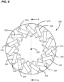
FIG. 6 illustrates a plan view of the disc ofFIG. 4 including rollers in the skewed roller slots in accordance with the principles of the present disclosure; -
FIG. 7 illustrates a side view of the disc ofFIG. 6 ; -
FIG. 8 illustrates a cross-sectional view taken along line 8-8 ofFIG. 6 ; -
FIG. 9 illustrates an enlarged view of a portion of the disc ofFIG. 8 ; -
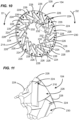
FIG. 10 illustrates a perspective view of a first side of the disc ofFIG. 6 with impeller flow channels and cutouts in accordance with the principles of the present disclosure; -
FIG. 11 illustrates an enlarged view of a portion of the disc ofFIG. 10 ; -
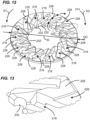
FIG. 12 illustrates another view of the disc ofFIG. 10 without the rollers; -
FIG. 13 illustrates an enlarged view of a portion of the disc ofFIG. 12 ; -
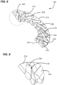
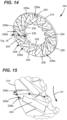
FIG. 14 illustrates a second side of the disc ofFIG. 6 illustrating impeller flow channels arranged at a reverse orientation to those shown inFIG. 10 ; -
FIG. 15 illustrates an enlarged view of a portion of the disc ofFIG. 14 ; -
FIG. 16 illustrates a perspective view of the disc ofFIG. 14 without the rollers; and -
FIG. 17 illustrates an enlarged view of a portion of the disc shown inFIG. 16 . - A rotary no-back device may be integrated within an aircraft flight control actuation system, such a flap and/or slat system. There may be other applications the no-back device may be integrated with, including but not limited to, fuel doors. The no-back capability of the rotary no-back device will prevent an aircraft flight control surface from being displaced from a desired position if a failure occurs to the actuation system's drive line.
- Referring to
FIG. 1 , a schematic representation of anexample aircraft 10 is presented. In general terms, theaircraft 10 includes afuselage 12, left andright wings vertical stabilizer 18, and left and righthorizontal stabilizers aircraft 10 is also provided with a number of primary flight control surfaces for operating theaircraft 10 during flight. Examples of such primary flight control surfaces areailerons spoilers right wings rudder 18a associated with thevertical stabilizer 18, andelevators horizontal stabilizers aircraft 10 is also shown as being provided withjet engines right wings - The
aircraft 10 is also provided with a number ofsecondary control surfaces 100 which are generally used during take-off and landing procedures. Examples of suchsecondary control surfaces 100 are slats 102 (102a - 102d) and flaps 106 (106a - 106c) associated with theleft wing 14, slats 104 (104a - 104d) and flaps 108 (108a - 108c) associated with theright wing 16, and thrust reversers 110 (110a, 110b), 112 (112a, 112b) respectively associated with the left andright engines - In one example use of the secondary control surfaces, the
slats wings slats wings aircraft 10 to take off more capably and under heavier loads. When takeoff is complete and theaircraft 10 enters a cruising phase, theslats wings slats aircraft 10. In one aspect, theslats - In another example use of the secondary control surfaces, thrust reversers 110, 112 can be activated into an extended position to temporarily divert the thrust of the
engines thrust reversers aircraft 10 to provide deceleration just after touchdown such that the diverted thrust acts against the forward travel of the aircraft. The incorporation ofthrust reversers aircraft 10 to land over a shorter distance and reduces the wear on the brakes of theaircraft 10. In one aspect, thethrust reversers - Although one example of an
aircraft 10 is presented with three examples of secondary control surfaces 100 (e.g.,slats 102/104, flaps 106/108, thrust reversers 110/112), many other configurations of theaircraft 10 andsecondary control surfaces 100 are possible without departing from the concepts presented herein. - Referring to
FIG. 2 , an examplerotary device assembly 200 is illustrated in accordance with principles of the present disclosure. In some examples, therotary device assembly 200 may be configured as a brake to transmit force which restricts rotation of a member. In accordance with the present disclosure, therotary device assembly 200 can relate generally to aircrafts, and in particular, to controlling the above-described primary and secondary control surfaces of theaircraft 10. However, it will be appreciated that therotary device assembly 200 may be used in a wide variety of applications. - The
rotary device assembly 200 may include anonrotatable brake member 202, tworoller bearing assemblies 204 disposed at least partially between a rotating member 206 (e.g., a ball screw, a shaft, etc.) and a stationary member 208 (e.g., a housing). It will be appreciated that therotary device assembly 200 may have a different construction. For example, therotary device assembly 200 may include a single skewedroller assembly 204. It will be appreciated that the tworoller bearing assemblies 204 can have the same construction and mode of operation. As such, only one skewedroller assembly 204 will be described in detail. - The
aircraft 10 may utilize therotary device assembly 200 for controlling various aircraft flight surfaces. In certain examples, the slats 102 (102a - 102d) and flaps 106 (106a - 106c) associated with theleft wing 14 and the slats 104 (104a - 104d) and flaps 108 (108a - 108c) associated with theright wing 16 can be pivoted by therotary device assembly 200 provided in flap actuators or slat actuators of theaircraft 10. Therotary device assembly 200 can be operably coupled to the left andright wings aircraft 10 and to an associated one or more of the slats/flaps rotary device assembly 200 is configured to transmit a torque from the rotatingmember 206 which is rotatable relative to thenonrotatable brake member 202. Therotary device assembly 200 can control pivoting of the slat/flap control surfaces with no-back capability. That is, therotary device assembly 200 can prevent a loss of position control of the primary or secondary control surfaces by grounding the resultant torque to a structural ground to thereby lock the primary or secondary control surfaces in a fixed position. For example, therotary device assembly 200 can be used to prevent loss of position control of the slats/flaps flaps - A signal can be sent from a main system processor to a control surface actuation system usable to operate control surfaces of the
aircraft 10, including but not limited to, the above-described primary and secondary control surfaces. The control surface can be driven by an actuator or multiple actuators. In some examples, a single actuator can be used to drive multiple control surfaces. In one aspect, the actuator can be used to drive a control surface by operating a member operably connected to the control surface. The actuator can be, for example, a linear acting actuator with a linear screw driven by a motor. In some examples, the member is operably connected to an actuator via a gear set, such as a planetary gear set. In some examples, the member is a part of an actuator, such as a shaft of an actuator. In some examples, a position sensor can be provided on an actuator for use in feedback control of the motor. The control surface can correspond to any of thecontrol surfaces 14a/b, 16a/b, 18a, 20a, 22a, 102, 104, 106, 108 shown inFIG. 1 . - The rotating
member 206 may be connected with a horizontal stabilizer on theaircraft 10. The rotatingmember 206 may extend along the longitudinalcentral axis 210 and have a terminal end operatively connectable to the flaps and/or slats. Theroller bearing assemblies 204 may facilitate rotation of the rotatingmember 206 relative to thenonrotatable brake member 202. The rotatingmember 206 is rotatable about its longitudinalcentral axis 210 while thestationary member 208 is held against rotation about the longitudinalcentral axis 210. The rotatingmember 206 has anannular flange 212 which is enclosed by thestationary member 208. The rotatingmember 206 and thus the flaps and/or slats of theaircraft 10 may be movable between a first retracted position and a second extended position. - The no-back capability of the
rotary device assembly 200 prevents movement of the rotatingmember 206 toward the retracted position in response to a compressive force generated by the flaps and/or slats. Depending on the direction in which the rotatingmember 206 overruns, theflange 212 may be pulled toward a respective one of the tworoller bearing assemblies 204. If the actuator extends as a result of pulling forces imparted to it by the flaps and/or slats, the no-back assembly is configured to resist that back driving force so it is not felt by the actuator. That is, if the flap applies a compressive force on the actuator, the actuator will not feel the external compressive force applied to it due to the no-back assembly designed to resist the back driving forces allowing the actuator to retract when driven to retract or extend when driven to extend. - Additional details about the construction and functioning of the
rotary device assembly 200 are provided inU.S. Patent No. 11,623,739 - Turning to
FIGS. 3-5 , the skewedroller assembly 204 may include a circular or annular disc 214 (e.g., retainer member) with an annular array of spaced apart skewed-roller slots 216. The skewed-roller slots 216 may be formed through thedisc 214. The circular orannular disc 214 may include one or more of a variety of shapes, sizes, configurations, and/or materials. Thedisc 214 may be a thin metallic ring that can be positioned against theflange 212. In certain examples, thedisc 214 may comprise a brass material, although alternatives are possible. In other examples, thedisc 214 may comprise a hardened steel, although alternatives are possible. In certain examples, thedisc 214 may be machined or printed using an additive manufacturing process, although alternatives are possible. - The skewed-
roller slots 216 may be rectangular slots that each extend generally in a radial direction. In certain examples, the skewed-roller slots 216 may be machined slots preferably evenly spaced around thedisc 214. It will be appreciated that the skewed-roller slots 216 may be formed using a variety of processes. Each of the skewed-roller slots 216 may have a longitudinalcentral axis 218 that is skewed at an angle α relative to a disc radius 220 (i.e., central axis) that extends through acenter 222 of the skewed-roller slot 216. That is, the skewed-roller slots 216 are skewed by an angle α relative to a radial line from thecenter 220 of thedisc 214. - The skewed-
roller slots 216 may be skewed at a specific angle to generate a desired amount of friction. The amount of friction can be determined by a subjected axial load and speed of an actuator drive shaft. In one example, the skewing angle α may be within the range of about 0 degrees to about 90 degrees. In certain examples, the skewing angle α may be within the range of about 30 degrees to about 60 degrees. In another example, the skewing angle α may be about 45 degrees. It will be appreciated that the skewing angle α may be optimized to provide a desired performance characteristics including, for example, friction and/or heat dissipation. - Referring to
FIGS. 6-9 , arespective roller 224 may be disposed in each of the skewed-roller slots 216. The skewed-roller slots 216 may be used for guiding and spacing therollers 224. Therollers 224 may be rotatably mounted in an annular array on the annular disc 214 a distance from the center ofrotation 220 of thedisc 214. Therollers 224 are rotatable in the skewed-roller slots 216 about theirrespective axis 218. Therollers 224 are effective to transmit force between a plate 225 (seeFIG. 2 ) connected with theflange 212 and thestationary member 208. When in use, therollers 224 can be subject to high thrust loads and torques, resulting in high rotational speeds of thedisc 214 and high friction on the roller surfaces which increases the temperature at the friction points. That is, friction may be transformed into and/or result in heat, and the amount of heat may correspond to a combination of thrust force, the coefficient of friction (COF), the friction radius R, and the spinning velocity of thedisc 214, which may correspond, for example, to the spinning velocity of the rotatingmember 206. In some applications, it may be desirable to balance the heat dissipation of rollers such that they dissipate comparable, similar, and/or substantially the same amount of heat, independent of the friction radii R of the rollers. - Typically, skewed rollers are partially submerged in a lubricating oil to help dissipate any heat generated in the system. Although partially immerged, high rotational speeds of a disc/cage and the orientation of the skewed rollers may cause the lubricating oil to be carried away by centrifugal forces from an inner diameter of the disc/cage. At high speeds and torques, centrifugal forces carry the lubricating oil away from the friction surfaces of the rollers. Without the lubricating oil, the friction surfaces are left without lubrication and a means of dissipating the heat generated which may cause the friction surfaces to overheat and cause a no-back system to fail.
- An advantageous feature of the skewed
roller assembly 204 configured according to the present disclosure is the ability to manage the direction of fluid flow in the system by forcing fluid (e.g., lubricating oil, etc.) to circulate around thedisc 214 continuously to lubricate therollers 224 in the skewedroller slots 216 and improve heat dissipation from the friction points. -
FIGS. 10-11 show a perspective view of the skewedroller assembly 204. Thedisc 214 includes a plurality of impeller flow channels 226 (e.g., slots) defined by impeller shapedstructures 228 arranged on a first side 230 (e.g., top side, high pressure side) of thedisc 214. That is, the plurality ofimpeller flow channels 226 are formed across a surface of thefirst side 230 from an outer periphery or outer diameter OD of thedisc 214 to an inner periphery or inner diameter ID of thedisc 214. The plurality ofimpeller flow channels 226 are arranged in an annular array on thefirst side 230 of thedisc 214 to force lubricating oil between the outer and inner peripheries. The lubricating oil is forced to circulate from the outer diameter OD (seeFIG. 12 ) of thedisc 214 to the inner diameter ID (seeFIG. 12 ) of thedisc 214 or vice versa. During use, for example when thedisc 214 is rotating clockwise, the lubricating oil is designed to flow through the plurality ofimpeller flow channels 226 on thefirst side 230 of thedisc 214 in a direction from the outer diameter OD toward the inner diameter ID. In certain examples, eachroller 224 extends across a respective one of theimpeller flow channels 226 so that lubricating fluid flowing through theimpeller flow channels 226 also flows over therollers 224. In certain examples, the center of therollers 224 may be positioned generally in a center of the plurality ofimpeller flow channels 226 to allow the lubricating oil to flow over therollers 224. - The
disc 214 further includescutouts 232, for example semi-circular cutouts, positioned at the inner diameter ID thereof. Thecutouts 232 allow lubricating oil to circulate between the first andsecond sides cutouts 232 allow thedisc 214 to keep tight tolerances for positioning thedisc 214 about the rotatingmember 206. Thecutouts 232 provide flow paths past the rotatingmember 206 to enable the lubricating oil to pass from one side of thedisc 214 to the other side of thedisc 214. Thecutouts 232 allow the lubricating oil to momentarily stay at the inner diameter ID. Thecutouts 232 can be defined at both the entrance and exit of the plurality ofimpeller flow channels 226. - Turning to
FIGS. 14-17 , perspective views of thedisc 214 is depicted showing the second side 234 (e.g., bottom side, low pressure side) thereof. A plurality ofimpeller flow channels 226a are defined by impeller shapedstructures 228a formed on thesecond side 234 of thedisc 214. The plurality ofimpeller flow channels 226a are arranged in a reverse orientation compared to the plurality ofimpeller flow channels 226 on thefirst side 230 of thedisc 214. That is, the plurality ofimpeller flow channels 226a can have a mirrored image to the plurality ofimpeller flow channels 226. - The plurality of
impeller flow channels sides disc 214. In one aspect, to provide this effect, theimpeller flow channels sidewalls FIG. 15 ). In the example shown, theimpeller flow channel first sidewall 226b can have a convex surface and thesecond sidewall 226c can have a concave surface. Thecutouts 232 are designed to scoop and circulate the lubricating oil from the inner diameter ID of one side of thedisc 214 to the opposite side and then outward to the outer diameter OD. That is, lubricating oil can exit the plurality ofimpeller flow channels 226 on thefirst side 230 of thedisc 214, pass through thecutouts 232, and enter the plurality ofimpeller flow channels 226a formed on thesecond side 234 of thedisc 214 to keep the lubricating oil circulating over and under thedisc 214 between the first andsecond sides - The
disc 214 can rotate either in a clockwise or counterclockwise direction. As such, the lubricating oil can be pulled from either thelower pressure side 234 to the higher-pressure side 230 of thedisc 214 or from the higher-pressure side 230 to thelower pressure side 234 of thedisc 214. - When the
disc 214 is rotating in a counterclockwise direction D1, the plurality ofimpeller flow channels 226 on thefirst side 230 can create a high-pressure force such that the lubricating oil flows over therollers 224 into the cutouts 232 (seeFIG. 11 ). The plurality ofimpeller flow channels 226 at thefirst side 230 can act as an impeller, such as a centrifugal pump impeller or a Francis turbine impeller, to create a boost and thereby flow. Thecutouts 232 are designed to scoop the lubricating oil against centrifugal forces such that the lubricating oil flows back over to thesecond side 234 of thedisc 214 where the pressure is lower. As the plurality ofimpeller flow channels 226a are oppositely arranged on thesecond side 234, theimpeller flow channels 226a on thesecond side 234 guide the lubricant oil from thecutouts 232 to the outer diameter OD of thedisc 214 when rotating in the direction D1 (seeFIG. 15 ), whereby the lubricant oil can be recaptured by theimpeller flow channels 226 on thefirst side 230. - When the
disc 214 is rotating in a clockwise direction D2, the plurality ofimpeller flow channels 226a at thesecond side 234, the opposite of the above-described dynamic occurs in which theimpeller flow channels 226a force the lubricant towards the inner diameter ID and thecutouts 232 and theimpeller flow channels 226 guide the lubricant back towards the outer diameter OD. - Examples of the disclosure may be described according to the following aspects.
- Aspect 1. A skewed roller assembly (204), comprising:
- a disc (214) having a plurality of skewed slots (216) defined therethrough; and
- a plurality of impeller flow channels (226) defined on a first side of the disc (214), each of the impeller flow channels (226) extending between inner and outer diameters (ID, OD) of the disc (214), each of the impeller flow channels (226) extending across a respective one of the skewed slots (216).
- Aspect 2. The skewed roller assembly of aspect 1, wherein the plurality of impeller flow channels (226) is a first plurality; and wherein a second plurality of impeller flow channels (226s) are defined at a second side of the disc (214), the second side being opposite the first side.
- Aspect 3. The skewed roller assembly of aspect 2, wherein the fluid is a lubricating oil.
- Aspect 4. The skewed roller assembly of aspect 2 or aspect 3, wherein the impeller flow channels (226a) of the second plurality are disposed in reverse orientation to the impeller flow channels (226) of the first plurality.
- Aspect 5. The skewed roller assembly of any of aspects 1-4, wherein a plurality of cutouts (232) are defined at an inner diameter of the disc (214), each of the impeller flow channels (226) extending to a respective one of the cutouts (232).
- Aspect 6. The skewed roller assembly of any of aspects 2-4, wherein a plurality of cutouts (232) are defined at an inner diameter of the disc (214), each cutout (232) forming a path from one of the impeller flow channels (226) of the first plurality to a corresponding impeller flow channel (226a) of the second plurality.
- Aspect 7. The skewed roller assembly of aspect 6, wherein fluid flow is directed to circulate through the first plurality of impeller flow channels (226), through the cutouts (232), and then through the second plurality of impeller flow channels (226a).
-
Aspect 8. The skewed roller assembly of any of aspects 5-7, wherein the cutouts (232) define semi-circles disposed about an inner circumference of the disc (214). - Aspect 9. The skewed roller assembly of any of aspects 5-8, wherein the cutouts (232) allow fluid to remain momentarily before circulating from the inner diameter (ID) out to the outer diameter (OD).
-
Aspect 10. The skewed roller assembly of any of aspects 1-9, wherein each one of the plurality of skewed slots (216) has a longitudinal axis (218) that extends through a center of the skewed slot (216), the longitudinal axis (218) being skewed at an angle relative to a radius (220) of the disc (214). - Aspect 11. The skewed roller assembly of any of aspects 1-10, wherein a plurality of rollers (224) are disposed at the disc (214), each roller (224) being retained at one of the skewed slots (216) so that the roller (224) extends across the respective impeller flow channel (226, 226a).
-
Aspect 12. The skewed roller assembly of any of aspects 1-11, wherein the plurality of skewed slots (216) are spaced in an annular array. - Aspect 13. The skewed roller assembly of any of aspects 1-12, wherein the impeller flow channels (226, 226a) of the first and second pluralities are oriented at an oblique angle relative to a radius line (220) of the disc (214).
-
Aspect 14. A rotary device (200) comprising: - a brake member (202);
- a rotating member (206) configured to rotate relative to the brake member (202), the rotating member (206) defining a flange (212); and
- the skewed roller assembly (204) as claimed in aspect 1, the skewed roller assembly (204) mounted over the rotating member (206), the skewed roller assembly (204) being axially disposed between the brake member (202) and the flange (212) of the rotating member (206).
- Aspect 15. The rotary device of
aspect 14, wherein the rotary device (200) is a no back rotary device. -
Aspect 16. A skewed roller assembly, comprising: - a disc having a first side and an opposite second side, the disc including an inner diameter and an outer diameter;
- a plurality of skewed slots defined through the disc;
- a roller retained in each one of the plurality of skewed slots;
- a first plurality of impeller flow channels defined on the first side of the disc;
- a second plurality of impeller flow channels defined on the second side of the disc, wherein the second plurality of impeller flow channels are formed in a reverse orientation to the first plurality of impeller flow channels; and
- cutouts positioned adjacent to the first and second pluralities of impeller flow channels to provide a fluid entrance and a fluid exit for continuously circulating fluid around the disc.
- Aspect 17. The skewed roller assembly of
aspect 16, wherein fluid flow is directed to circulate through the first plurality of impeller flow channels, through the cutouts, and then through the second plurality of impeller flow channels. -
Aspect 18. The skewed roller assembly ofaspect 16, wherein the cutouts are defined at the inner diameter of the disc. - Aspect 19. The skewed roller assembly of
aspect 16, wherein the fluid is a lubricating oil. -
Aspect 20. The skewed roller assembly ofaspect 16, wherein each one of the plurality of skewed slots has a longitudinal axis that extends through a center of the skewed slot, the longitudinal axis being skewed at an angle relative to a disc radius. - Aspect 21. The skewed roller assembly of
aspect 16, wherein the plurality of skewed slots are spaced in an annular array. -
Aspect 22. The skewed roller assembly of aspect 21, wherein the plurality of skewed slots have a skewing angle within the range of about 0 degrees to about 90 degrees. - Aspect 23. The skewed roller assembly of aspect 21, wherein the plurality of skewed slots have a skewing angle within the range of about 30 degrees to about 60 degrees.
-
Aspect 24. The skewed roller assembly ofaspect 16, wherein the first and second pluralities of impeller flow channels include sidewalls oriented at an oblique angle relative to a radius line of the disc. - Aspect 25. A skewed roller assembly, comprising:
- a disc having a plurality of skewed slots defined therethrough;
- a roller retained in each one of the plurality of skewed slots; and
- a plurality of impeller flow channels defined on a first side of the disc, each of the impeller flow channels extending past a respective one of the skewed slots so that each roller extends across a respective one of the impeller flow channels.
-
Aspect 26. The skewed roller assembly of claim 25, wherein a plurality of cutouts are defined at an inner diameter of the disc, each of the impeller flow channels extending to a respective one of the cutouts. - Aspect 27. The skewed roller assembly of aspect 25, wherein the plurality of impeller flow channels is a first plurality; and wherein a second plurality of impeller flow channels are defined at a second side of the disc, the second side being opposite the first side.
- Aspect 28. The skewed roller assembly of aspect 27, wherein the impeller flow channels of the second plurality are disposed in reverse orientation to the impeller flow channels of the first plurality.
- Aspect 29. The skewed roller assembly of aspect 28, wherein a plurality of cutouts are defined at an inner diameter of the disc, each cutout forming a path from one of the impeller flow channels of the first plurality to a corresponding impeller flow channel of the second plurality.
- Aspect 30. The skewed roller assembly of aspect 25, wherein the cutouts allow fluid to remain momentarily before circulating from the inner diameter out to the outer diameter.
- Aspect 31. The skewed roller assembly of aspect 25, wherein the fluid is a lubricating oil.
- Aspect 32. The skewed roller assembly of aspect 25, wherein each one of the plurality of skewed slots has a longitudinal axis that extends through a center of the skewed slot, the longitudinal axis being skewed at an angle relative to a radius of the disc.
- Aspect 33. A disc for use in a skewed roller assembly, comprising:
- a main body defining a plurality of skewed slots therethrough;
- a first plurality of impeller flow channels defined on a top side of the main body;
- a second plurality of impeller flow channels defined on a bottom side of the main body, wherein the second plurality of impeller flow channels are formed in a reverse orientation to the first plurality of impeller flow channels, the first and second pluralities of impeller flow channels each having entrance and exit points at an inner diameter of the main body.
- Aspect 34. The disc of aspect 33, wherein a plurality of cutouts are positioned adjacent to the entrance and exit points of the first and second pluralities of impeller flow channels.
- Aspect 35. The disc of aspect 33, wherein the cutouts define semi-circles disposed about an inner circumference of the disc.
- Various modifications and alterations of this disclosure will become apparent to those skilled in the art without departing from the scope and spirit of this disclosure, and it should be understood that the inventive scope of this disclosure is not to be unduly limited to the illustrative embodiments set forth herein.
Claims (15)
- A skewed roller assembly (204), comprising:a disc (214) having a plurality of skewed slots (216) defined therethrough; anda plurality of impeller flow channels (226) defined on a first side of the disc (214), each of the impeller flow channels (226) extending between inner and outer diameters (ID, OD) of the disc (214), each of the impeller flow channels (226) extending across a respective one of the skewed slots (216).
- The skewed roller assembly of claim 1, wherein the plurality of impeller flow channels (226) is a first plurality; and wherein a second plurality of impeller flow channels (226s) are defined at a second side of the disc (214), the second side being opposite the first side.
- The skewed roller assembly of claim 2, wherein the fluid is a lubricating oil.
- The skewed roller assembly of claim 2 or claim 3, wherein the impeller flow channels (226a) of the second plurality are disposed in reverse orientation to the impeller flow channels (226) of the first plurality.
- The skewed roller assembly of any of claims 1-4, wherein a plurality of cutouts (232) are defined at an inner diameter of the disc (214), each of the impeller flow channels (226) extending to a respective one of the cutouts (232).
- The skewed roller assembly of any of claims 2-4, wherein a plurality of cutouts (232) are defined at an inner diameter of the disc (214), each cutout (232) forming a path from one of the impeller flow channels (226) of the first plurality to a corresponding impeller flow channel (226a) of the second plurality.
- The skewed roller assembly of claim 6, wherein fluid flow is directed to circulate through the first plurality of impeller flow channels (226), through the cutouts (232), and then through the second plurality of impeller flow channels (226a).
- The skewed roller assembly of any of claims 5-7, wherein the cutouts (232) define semi-circles disposed about an inner circumference of the disc (214).
- The skewed roller assembly of any of claims 5-8, wherein the cutouts (232) allow fluid to remain momentarily before circulating from the inner diameter (ID) out to the outer diameter (OD).
- The skewed roller assembly of any of claims 1-9, wherein each one of the plurality of skewed slots (216) has a longitudinal axis (218) that extends through a center of the skewed slot (216), the longitudinal axis (218) being skewed at an angle relative to a radius (220) of the disc (214).
- The skewed roller assembly of any of claims 1-10, wherein a plurality of rollers (224) are disposed at the disc (214), each roller (224) being retained at one of the skewed slots (216) so that the roller (224) extends across the respective impeller flow channel (226, 226a).
- The skewed roller assembly of any of claims 1-11, wherein the plurality of skewed slots (216) are spaced in an annular array.
- The skewed roller assembly of any of claims 1-12, wherein the impeller flow channels (226, 226a) of the first and second pluralities are oriented at an oblique angle relative to a radius line (220) of the disc (214).
- A rotary device (200) comprising:a brake member (202);a rotating member (206) configured to rotate relative to the brake member (202), the rotating member (206) defining a flange (212); andthe skewed roller assembly (204) as claimed in claim 1, the skewed roller assembly (204) mounted over the rotating member (206), the skewed roller assembly (204) being axially disposed between the brake member (202) and the flange (212) of the rotating member (206).
- The rotary device of claim 14, wherein the rotary device (200) is a no back rotary device.
Applications Claiming Priority (1)
| Application Number | Priority Date | Filing Date | Title |
|---|---|---|---|
| US202263334554P | 2022-04-25 | 2022-04-25 |
Publications (1)
| Publication Number | Publication Date |
|---|---|
| EP4269234A1 true EP4269234A1 (en) | 2023-11-01 |
Family
ID=86226644
Family Applications (1)
| Application Number | Title | Priority Date | Filing Date |
|---|---|---|---|
| EP23169750.9A Pending EP4269234A1 (en) | 2022-04-25 | 2023-04-25 | Skewed roller impeller cage for use with a rotary no-back device |
Country Status (2)
| Country | Link |
|---|---|
| US (1) | US12510127B2 (en) |
| EP (1) | EP4269234A1 (en) |
Cited By (1)
| Publication number | Priority date | Publication date | Assignee | Title |
|---|---|---|---|---|
| EP4632212A1 (en) * | 2024-04-01 | 2025-10-15 | Hamilton Sundstrand Corporation | Actuator with back-to-back clutch and a no-back unit for an engine nacelle and a method of assembling an engine nacelle comprising the same |
Citations (5)
| Publication number | Priority date | Publication date | Assignee | Title |
|---|---|---|---|---|
| US6109415A (en) * | 1998-05-29 | 2000-08-29 | The Boeing Company | Bi-directional ballscrew no-back device |
| US8393568B2 (en) * | 2006-07-17 | 2013-03-12 | Eaton Corporation | Enhanced lubrication skewed roller clutch assembly and actuator including same |
| US9810261B1 (en) * | 2016-06-02 | 2017-11-07 | Eaton Corporation | Bearing |
| US20200148330A1 (en) * | 2014-07-18 | 2020-05-14 | Hamilton Sundstrand Corporation | Hybrid torque limiting rotary no-back device |
| US11623739B2 (en) | 2020-10-27 | 2023-04-11 | Eaton Intelligent Power Limited | Electromechanical actuator with no-back system |
Family Cites Families (24)
| Publication number | Priority date | Publication date | Assignee | Title |
|---|---|---|---|---|
| US3081842A (en) | 1959-09-16 | 1963-03-19 | Lambert & Brake Corp | Fluid-cooled heavy duty disc brake |
| US3897860A (en) | 1973-11-19 | 1975-08-05 | Borg Warner | Wet clutch with coolant distributor |
| US5101953A (en) * | 1986-09-16 | 1992-04-07 | Borg-Warner Automotive Transmission & Engine Components Corporation | High capacity viscous pumping groove pattern for a wet clutch |
| US4850458A (en) * | 1988-11-16 | 1989-07-25 | Boeing Company | Bidirectional rotary brake |
| US5183139A (en) | 1992-01-09 | 1993-02-02 | Borg-Warner Automotive Transmission & Engine Components Corporations | Overrunning clutch having a cage design for directing lube flow |
| JP3020017B2 (en) * | 1994-11-07 | 2000-03-15 | 大同メタル工業株式会社 | Wet friction member |
| US5582390A (en) * | 1994-11-17 | 1996-12-10 | Sundstrand Corporation | Drive apparatus with primary and secondary no-back features |
| DE69619277T2 (en) * | 1996-03-01 | 2002-10-24 | Kenji Mimura | FRICTION RESISTANCE GENERATOR |
| EP0979360B1 (en) | 1997-04-28 | 2004-06-16 | Means Industries, Inc. | Controllable overrunning coupling |
| JP3454502B2 (en) | 2000-03-15 | 2003-10-06 | Thk株式会社 | Lubricating oil supply device and rolling element screw device using the same |
| DE10107706A1 (en) | 2001-02-19 | 2002-10-02 | Rexroth Star Gmbh | Rotary bearing with lubrication channel arrangement, screw drive with rotating screw nut |
| DE10118921A1 (en) * | 2001-04-18 | 2002-11-14 | Sgl Carbon Ag | Friction disk and process for its manufacture |
| DE10305842B4 (en) | 2003-02-12 | 2015-07-09 | Matec Maschinenbau Gmbh | Spindle drive and machine tools with such a spindle drive |
| US6997297B2 (en) * | 2004-03-09 | 2006-02-14 | Eaton Corporation | Coupling assembly |
| WO2006035650A1 (en) | 2004-09-27 | 2006-04-06 | Ntn Corporation | Constant velocity universal joint and method of producing the same |
| AU2006220071A1 (en) * | 2005-03-03 | 2006-09-08 | Knorr-Bremse Systeme Fur Nutzfahrzeuge Gmbh | Brake-disc, in particular for a vehicle |
| JP2007192252A (en) | 2006-01-17 | 2007-08-02 | Jtekt Corp | Thrust roller bearing |
| US20080302616A1 (en) * | 2007-06-11 | 2008-12-11 | Ching-Wen Kao | Brake disk with grooves |
| JP5596575B2 (en) | 2011-01-21 | 2014-09-24 | Ntn株式会社 | Electric linear actuator and electric disc brake device |
| CN104454969A (en) | 2013-09-16 | 2015-03-25 | 天津日望环境技术有限公司 | Damping bearing |
| DE102015223641A1 (en) | 2015-06-10 | 2016-12-15 | Sms Group Gmbh | Device for transmitting a torque from a drive device to a roller in a rolling stand |
| FR3063532B1 (en) * | 2017-03-06 | 2019-04-05 | Safran Electronics & Defense | ACTUATOR EQUIPPED WITH A NO BACK SYSTEM WITH INHIBITION AREA |
| JP2018179009A (en) | 2017-04-03 | 2018-11-15 | 日本精工株式会社 | Thrust cylindrical roller bearing |
| EP4265931B1 (en) * | 2022-04-21 | 2025-02-12 | Goodrich Actuation Systems SAS | Asymmetric mechanical torque limiter |
-
2023
- 2023-04-25 EP EP23169750.9A patent/EP4269234A1/en active Pending
- 2023-04-25 US US18/306,590 patent/US12510127B2/en active Active
Patent Citations (5)
| Publication number | Priority date | Publication date | Assignee | Title |
|---|---|---|---|---|
| US6109415A (en) * | 1998-05-29 | 2000-08-29 | The Boeing Company | Bi-directional ballscrew no-back device |
| US8393568B2 (en) * | 2006-07-17 | 2013-03-12 | Eaton Corporation | Enhanced lubrication skewed roller clutch assembly and actuator including same |
| US20200148330A1 (en) * | 2014-07-18 | 2020-05-14 | Hamilton Sundstrand Corporation | Hybrid torque limiting rotary no-back device |
| US9810261B1 (en) * | 2016-06-02 | 2017-11-07 | Eaton Corporation | Bearing |
| US11623739B2 (en) | 2020-10-27 | 2023-04-11 | Eaton Intelligent Power Limited | Electromechanical actuator with no-back system |
Cited By (1)
| Publication number | Priority date | Publication date | Assignee | Title |
|---|---|---|---|---|
| EP4632212A1 (en) * | 2024-04-01 | 2025-10-15 | Hamilton Sundstrand Corporation | Actuator with back-to-back clutch and a no-back unit for an engine nacelle and a method of assembling an engine nacelle comprising the same |
Also Published As
| Publication number | Publication date |
|---|---|
| US12510127B2 (en) | 2025-12-30 |
| US20240360881A1 (en) | 2024-10-31 |
Similar Documents
| Publication | Publication Date | Title |
|---|---|---|
| EP2617978B1 (en) | Integrated thrust reverser actuator and variable area fan nozzle actuator | |
| CA1068493A (en) | Dual output variable pitch turbofan actuation system | |
| US7309043B2 (en) | Actuation device positioning systems and associated methods, including aircraft spoiler droop systems | |
| US4842484A (en) | Blade gearing and pitch changing mechanisms for coaxial counterrotating propellers | |
| EP2440453B1 (en) | Device for actuating a control surface of an aircraft | |
| EP4049925B1 (en) | An actuator assembly for moving a movable wing tip of an aircraft | |
| US11964751B2 (en) | Aircraft actuator with no-back, load detent assembly | |
| CA1258846A (en) | Aircraft propeller system | |
| CN102458985A (en) | Enhanced lubrication skewed roller clutch assembly and actuator including it | |
| EP2332829A2 (en) | Passive cyclic pitch control | |
| US12510127B2 (en) | Skewed roller impeller cage for use with a rotary no-back device | |
| US3212586A (en) | Pitch control system | |
| US9517839B2 (en) | Electromechanical linear actuator for in blade rotor control | |
| EP2340993B1 (en) | Propeller assembly pitch change apparatus | |
| CN111152911B (en) | Torsional deformation control device and method for flexible wing | |
| EP4160048B1 (en) | Ball screw rotary actuator with ball cage | |
| US20250146563A1 (en) | Fault tolerant rotary ema | |
| US7028602B2 (en) | Linear, hydraulic pivot drive | |
| US20240183325A1 (en) | Traveling finger lock for an actuator | |
| US11667374B2 (en) | Blade pitch actuation mechanism | |
| EP4265931B1 (en) | Asymmetric mechanical torque limiter | |
| US20230115546A1 (en) | Self-activated no-back device | |
| EP3318776B1 (en) | Rotating no-back brake system | |
| EP2942273B1 (en) | A unison ring system | |
| CN120773908A (en) | Rotating type unconventional pneumatic control surface structure of aircraft wing and control method thereof |
Legal Events
| Date | Code | Title | Description |
|---|---|---|---|
| PUAI | Public reference made under article 153(3) epc to a published international application that has entered the european phase |
Free format text: ORIGINAL CODE: 0009012 |
|
| STAA | Information on the status of an ep patent application or granted ep patent |
Free format text: STATUS: REQUEST FOR EXAMINATION WAS MADE |
|
| 17P | Request for examination filed |
Effective date: 20230425 |
|
| AK | Designated contracting states |
Kind code of ref document: A1 Designated state(s): AL AT BE BG CH CY CZ DE DK EE ES FI FR GB GR HR HU IE IS IT LI LT LU LV MC ME MK MT NL NO PL PT RO RS SE SI SK SM TR |
|
| STAA | Information on the status of an ep patent application or granted ep patent |
Free format text: STATUS: EXAMINATION IS IN PROGRESS |
|
| 17Q | First examination report despatched |
Effective date: 20250512 |
|
| REG | Reference to a national code |
Ref country code: DE Ref legal event code: R079 Free format text: PREVIOUS MAIN CLASS: B64C0013240000 Ipc: F16D0059000000 |
|
| GRAP | Despatch of communication of intention to grant a patent |
Free format text: ORIGINAL CODE: EPIDOSNIGR1 |
|
| STAA | Information on the status of an ep patent application or granted ep patent |
Free format text: STATUS: GRANT OF PATENT IS INTENDED |
|
| RIC1 | Information provided on ipc code assigned before grant |
Ipc: F16D 59/00 20060101AFI20260108BHEP Ipc: F16D 65/02 20060101ALI20260108BHEP Ipc: B64C 13/24 20060101ALI20260108BHEP Ipc: F16D 65/78 20060101ALI20260108BHEP Ipc: F16D 41/064 20060101ALN20260108BHEP |
|
| INTG | Intention to grant announced |
Effective date: 20260128 |