EP4269232A1 - Fairing attachment system for a wing of an aircraft, aircraft wing and method for mounting a fairing device - Google Patents
Fairing attachment system for a wing of an aircraft, aircraft wing and method for mounting a fairing device Download PDFInfo
- Publication number
- EP4269232A1 EP4269232A1 EP22170667.4A EP22170667A EP4269232A1 EP 4269232 A1 EP4269232 A1 EP 4269232A1 EP 22170667 A EP22170667 A EP 22170667A EP 4269232 A1 EP4269232 A1 EP 4269232A1
- Authority
- EP
- European Patent Office
- Prior art keywords
- fairing
- wing
- attachment
- adjustable
- high lift
- Prior art date
- Legal status (The legal status is an assumption and is not a legal conclusion. Google has not performed a legal analysis and makes no representation as to the accuracy of the status listed.)
- Granted
Links
Images

Classifications
-
- B—PERFORMING OPERATIONS; TRANSPORTING
- B64—AIRCRAFT; AVIATION; COSMONAUTICS
- B64C—AEROPLANES; HELICOPTERS
- B64C7/00—Structures or fairings not otherwise provided for
-
- B—PERFORMING OPERATIONS; TRANSPORTING
- B64—AIRCRAFT; AVIATION; COSMONAUTICS
- B64C—AEROPLANES; HELICOPTERS
- B64C3/00—Wings
- B64C3/38—Adjustment of complete wings or parts thereof
- B64C3/44—Varying camber
- B64C3/50—Varying camber by leading or trailing edge flaps
-
- B—PERFORMING OPERATIONS; TRANSPORTING
- B64—AIRCRAFT; AVIATION; COSMONAUTICS
- B64C—AEROPLANES; HELICOPTERS
- B64C9/00—Adjustable control surfaces or members, e.g. rudders
- B64C9/02—Mounting or supporting thereof
-
- B—PERFORMING OPERATIONS; TRANSPORTING
- B64—AIRCRAFT; AVIATION; COSMONAUTICS
- B64C—AEROPLANES; HELICOPTERS
- B64C9/00—Adjustable control surfaces or members, e.g. rudders
- B64C9/14—Adjustable control surfaces or members, e.g. rudders forming slots
- B64C9/16—Adjustable control surfaces or members, e.g. rudders forming slots at the rear of the wing
Definitions
- the invention relates to a fairing attachment system for attachment of a fairing device to a wing of an aircraft, an aircraft wing, and a method for mounting a fairing device to a wing of an aircraft.
- Modern aircrafts usually comprise wings having adjustable high lift airfoil devices which can be moved rotatably and translatory relative to the wing.
- Such high lift airfoil devices may be e.g. flaps and/or flaperons, which combine the functions of flaps and ailerons. They are driven by adjustment mechanisms comprising high lift support structures, which are exposed to high loads during flight and usually project beyond the underside of the wing on which the adjustable high lift airfoil devices are arranged.
- the high lift support structures are aerodynamically enclosed or covered by fairing elements or devices.
- the high lift support structures are assembled to the wing with close tolerances.
- the object is achieved by the fairing attachment system according to claim 1, the aircraft wing according to claim 11, and the method for mounting a fairing device to a wing of an aircraft according to claim 12.
- the invention provides a fairing attachment system for a wing of an aircraft, the fairing attachment system comprising a high lift support structure configured for movable supporting a high-lift airfoil element of a wing of an aircraft relative to the wing; a fairing device extending in a lengthwise direction, configured for providing an aerodynamic cover or housing of the high lift support structure when attached to a surface of the wing; an adjustable attachment element configured for attachment of the fairing device to the high lift support structure, wherein the adjustable attachment element is longitudinally extending and adjustable in length in order to compensate tolerances of the high lift support structure relative to the wing during assembly.
- the invention provides a fairing to wing connection which allows a quick installation of a fairing to a wing independently from the position and orientation of the high lift support structure relatively to the wing.
- High rates capable equipping of the flap on the wing and reducing cost and lead time in the final assembly line are achieved.
- the invention enables modular installation of high lift devices like e.g. flaps and flaperons with minimizing the number of connections to the wingbox, thus reducing complexity of installation.
- fairing installation independently from the high lift support structure is achieved.
- the fairing attachment system is designed for attachment of the fairing device to the aircraft.
- the high lift support structure is e.g. configured for movable attachment to the wing.
- the high lift airfoil element may e.g. be a flap or a flaperon.
- the adjustable attachment element is configured for being pivotally mounted to the high lift support structure.
- At least a component of a pivot axis of the pivotally mounted adjustable attachment element extends in the lengthwise direction of the fairing device.
- the fairing attachment system further comprises a support element configured for supporting the fairing device at the wing at a position distant from the adjustable attachment element in the lengthwise direction of the fairing device.
- the support element provides a rotational degree of freedom, wherein the rotation axis of the support element corresponds to the pivot axis of the adjustable attachment element.
- a second pivot axis of the adjustable attachment element extends in the spanwise direction of the wing.
- the fairing attachment system further comprises a seal element configured for being mounted between the fairing device and the wing, the seal advantageously being compressible by adjustment of the adjustable attachment element, e.g. in order to control a gap between the fairing device and the wing.
- the fairing device comprises a fixed fairing element and a movable fairing element which can be moved by the high lift support structure e.g. relative to the fixed fairing element, wherein the adjustable attachment element is preferably configured for attachment of the movable fairing element to the high lift support structure.
- the adjustable fairing element is configured as a strut for an aft attachment of the fairing device.
- the support element is configured as a bracket for providing a front attachment of the fairing device.
- an aircraft wing comprising a high lift airfoil arrangement, a fairing device and a fairing attachment system according to the invention is provided.
- a method for mounting a fairing device to a wing of an aircraft wherein a fairing attachment system according to the invention is used.
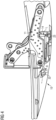
- FIG. 1 depicts a section of a wing 10 comprising a fairing attachment system according to a preferred embodiment of the invention.
- the fairing attachment system comprises a high lift support structure 11, which is configured as a kinematic support rib and designed for supporting and moving a high lift airfoil element designed as a flap 17 of wing 10. It further comprises a fairing device 12 which forms an aerodynamic housing covering the kinematic support rib 11 at the underside 13 of wing 10.
- the fairing attachment system comprises an adjustable attachment element 14 realized by a strut for attaching the fairing device 12 to the high lift support structure 11.
- the attachment element or strut 14 is longitudinally extending and adjustable in length in order to compensate tolerances of the high lift support structure 11 relative to the wing 10 during assembly.
- the fairing device 12 extends in a lengthwise direction X which corresponds to the longitudinal axis of the aircraft and the wing 10. It comprises a fixed fairing element 15 which forms a forward portion of the fairing device 12, and a movable fairing element 16, which forms an aft portion of the fairing device 12.
- the wing 10 comprises flap 17 as a high-lift airfoil element located at the trailing edge of the wing 10. Flap 17 is mechanically connected to the distal end 18 of an arm 19 of the kinematic support rib 11.
- Kinematic support rib 11 comprises a first fastener element 20 designed as a bolt and located at an end of support rib 11 opposite to the distal end 18. By the fastener element 20, kinematic support rib 11 is rotatably mounted within the wing 10.
- Support rib 11 comprises two support rib elements 11a, 11b formed as plates which are aligned parallel to each other with a distance between them.
- Support rib 11 further comprises a second fastener element 21 designed as a bolt and located at a further portion of the arm 19 of support rib 11.
- kinematic support arm 19 is rotatably mounted below the underside 13 of the wing 10.
- the distal end 18 of arm 19 is able to pivot around a pivot axis extending in the spanwise direction of the wing 10, i.e. arm 19 is pivotable around the longitudinal axis of bolt 20.
- flap 17 connected to distal end 18 of the arm 19 is moved by the rotational movement of kinematic support rib 11, which is built as a double rib and driven by driving means not shown in the figure.
- a support element 22 formed by a support bracket of the wing 10 is fixedly connected to the wing 10 and mechanically connects a portion of the fixed fairing element 15 to the wing 10, thus forming a forward attachment of the fixed fairing element 15.
- the forward attachment provides a rotational degree of freedom for the fixed fairing element 15, which will be explained in more detail further below.
- the wing fixed bracket 22 is installed during wing box assembly with close tolerances. The bracket 22 is used to attach the fairing by two bolts and serves as the forward attachment of the fixed fairing 15.
- strut 14 One end of strut 14 is attached to kinematic arm 19 of kinematic support rib 11 which is mechanically connected to the flap 17.
- the opposite end of strut 14 is attached to a support bracket 23 of the fixed fairing element 15, thus forming an aft attachment of the fixed fairing element 15.
- the fixed fairing element 15 is attached to the kinematic support rib 11 by strut 14.
- the fairing bracket 23 or aft attachment of the fixed fairing element 15 is located at a position distant from the forward attachment 22 in the longitudinal direction X of the wing 10 and the aircraft.
- the location of the support bracket 23 depends on the location of the kinematic support rib 11.
- Strut 14 installed at the aft attachment can be adjusted in length in order to compensate resulting tolerances of the high lift support rib 11 to wing assembly, i.e. during the final assembly line process.
- the final position of the fixed fairing element 15 is independent from the position of the kinematic support rib 15 which is usually installed with close tolerances.
- a seal 31 located between fairing 15 and wing 10 is compressible by the adjustment of strut 14 in order to control a gap between fairing 15 and wing 10.
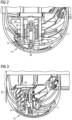
- Figures 2 and 3 depict the double kinematic support rib 11, the fixed fairing element 15 of fairing device 12, and the adjustable strut 14 attached to fixed fairing element 15 as a front view.
- Figure 2 shows the kinematic support rib 11 in a nominal position
- figure 3 depicts the support rib 11 in a position where it is misaligned due to build tolerances. Both figures show the situation after installation of strut 14 in order to attach fixed fairing 15 to kinematic support rib 11.
- strut 14 When the support rib 11 is in its nominal position, strut 14 is installed with its nominal length, as can be seen from figure 2 . However, when support rib 11 is misaligned due to build tolerances as shown in figure 3 , strut 14 is adjusted in length.
- end 24 of strut 14 attached to support rib 11 is pivotally installed in a support element 25 designed as a bracket and being part of support rib 11. Further, the opposite end 26 of strut 14 is also pivotally installed in support element or bracket 23 of the fixed fairing element 15.
- strut 14 is able to pivot around pivot axes extending through support elements 23 and 25 perpendicular to the image plane of figures 2 and 3 , i.e. in the direction X indicated in figure 1 , which corresponds to the longitudinal or forward direction of the wing 10 and the aircraft.
- strut 14 compensates an angular mismatch due to the misalignment of support rib 11.
- Figure 4 shows the length adjustment L of the strut 14 attached to fixed fairing element 15 at one side and to kinematic support rib 11 at the opposite side, as well as the rotational degree of freedom R provided by the forward attachment 22 and by the aft attachment 23 of fixed fairing element 15.
Landscapes
- Engineering & Computer Science (AREA)
- Aviation & Aerospace Engineering (AREA)
- Aerodynamic Tests, Hydrodynamic Tests, Wind Tunnels, And Water Tanks (AREA)
- Connection Of Plates (AREA)
Abstract
Description
- The invention relates to a fairing attachment system for attachment of a fairing device to a wing of an aircraft, an aircraft wing, and a method for mounting a fairing device to a wing of an aircraft.
- Modern aircrafts usually comprise wings having adjustable high lift airfoil devices which can be moved rotatably and translatory relative to the wing. Such high lift airfoil devices may be e.g. flaps and/or flaperons, which combine the functions of flaps and ailerons. They are driven by adjustment mechanisms comprising high lift support structures, which are exposed to high loads during flight and usually project beyond the underside of the wing on which the adjustable high lift airfoil devices are arranged. The high lift support structures are aerodynamically enclosed or covered by fairing elements or devices. Typically, the high lift support structures are assembled to the wing with close tolerances.
- The installation of the fairing to the wing is time consuming and thus leads to relatively high costs, as the position and the orientation of the high lift support structure relative to the wing needs exactly to be considered when the fairing is mounted. This is quite often particularly difficult because of the high number of connections to the wingbox.
- It is the object of the invention to allow a quicker installation of a fairing to a wing, to provide high rates when equipping wings with flaps, and to reduce lead time.
- The object is achieved by the fairing attachment system according to claim 1, the aircraft wing according to
claim 11, and the method for mounting a fairing device to a wing of an aircraft according toclaim 12. - The invention provides a fairing attachment system for a wing of an aircraft, the fairing attachment system comprising a high lift support structure configured for movable supporting a high-lift airfoil element of a wing of an aircraft relative to the wing; a fairing device extending in a lengthwise direction, configured for providing an aerodynamic cover or housing of the high lift support structure when attached to a surface of the wing; an adjustable attachment element configured for attachment of the fairing device to the high lift support structure, wherein the adjustable attachment element is longitudinally extending and adjustable in length in order to compensate tolerances of the high lift support structure relative to the wing during assembly.
- The invention provides a fairing to wing connection which allows a quick installation of a fairing to a wing independently from the position and orientation of the high lift support structure relatively to the wing. High rates capable equipping of the flap on the wing and reducing cost and lead time in the final assembly line are achieved. Moreover, the invention enables modular installation of high lift devices like e.g. flaps and flaperons with minimizing the number of connections to the wingbox, thus reducing complexity of installation. In particular, fairing installation independently from the high lift support structure is achieved. The fairing attachment system is designed for attachment of the fairing device to the aircraft.
- The high lift support structure is e.g. configured for movable attachment to the wing. In particular, the high lift airfoil element may e.g. be a flap or a flaperon.
- Preferably, the adjustable attachment element is configured for being pivotally mounted to the high lift support structure.
- Preferably, at least a component of a pivot axis of the pivotally mounted adjustable attachment element extends in the lengthwise direction of the fairing device.
- Preferably, the fairing attachment system further comprises a support element configured for supporting the fairing device at the wing at a position distant from the adjustable attachment element in the lengthwise direction of the fairing device.
- Preferably, the support element provides a rotational degree of freedom, wherein the rotation axis of the support element corresponds to the pivot axis of the adjustable attachment element.
- Preferably, a second pivot axis of the adjustable attachment element extends in the spanwise direction of the wing.
- Preferably, the fairing attachment system further comprises a seal element configured for being mounted between the fairing device and the wing, the seal advantageously being compressible by adjustment of the adjustable attachment element, e.g. in order to control a gap between the fairing device and the wing.
- Preferably, the fairing device comprises a fixed fairing element and a movable fairing element which can be moved by the high lift support structure e.g. relative to the fixed fairing element, wherein the adjustable attachment element is preferably configured for attachment of the movable fairing element to the high lift support structure.
- Preferably, the adjustable fairing element is configured as a strut for an aft attachment of the fairing device.
- Preferably, the support element is configured as a bracket for providing a front attachment of the fairing device.
- According to an aspect of the invention, an aircraft wing comprising a high lift airfoil arrangement, a fairing device and a fairing attachment system according to the invention is provided.
- According to a further aspect of the invention, a method for mounting a fairing device to a wing of an aircraft is provided, wherein a fairing attachment system according to the invention is used.
- Embodiments of the invention are described in more detail with reference to the accompanying drawings. In the drawings
- Figs. 1
- depicts a wing section with a fairing attachment system according to a preferred embodiment of the invention, as a 3-dimensional partial cut view;
- Fig. 2
- depicts a front view of the fairing attachment system shown in
Fig. 1 , with a support rib in a nominal position; - Fig. 3
- depicts a front view of the fairing attachment system shown in
Fig. 1 , wherein the support rib is misaligned due to build tolerances; and - Fig. 4
- depicts the fairing attachment system shown in
Fig. 1 , wherein a rotational degree of freedom provided by a support element and a length adjustment of an adjustable attachment element are indicated as arrows. -
Figure 1 depicts a section of awing 10 comprising a fairing attachment system according to a preferred embodiment of the invention. The fairing attachment system comprises a highlift support structure 11, which is configured as a kinematic support rib and designed for supporting and moving a high lift airfoil element designed as aflap 17 ofwing 10. It further comprises afairing device 12 which forms an aerodynamic housing covering thekinematic support rib 11 at theunderside 13 ofwing 10. Further, the fairing attachment system comprises anadjustable attachment element 14 realized by a strut for attaching thefairing device 12 to the highlift support structure 11. The attachment element orstrut 14 is longitudinally extending and adjustable in length in order to compensate tolerances of the highlift support structure 11 relative to thewing 10 during assembly. - The
fairing device 12 extends in a lengthwise direction X which corresponds to the longitudinal axis of the aircraft and thewing 10. It comprises a fixedfairing element 15 which forms a forward portion of thefairing device 12, and a movable fairing element 16, which forms an aft portion of thefairing device 12. - The
wing 10 comprisesflap 17 as a high-lift airfoil element located at the trailing edge of thewing 10.Flap 17 is mechanically connected to thedistal end 18 of anarm 19 of thekinematic support rib 11.Kinematic support rib 11 comprises afirst fastener element 20 designed as a bolt and located at an end ofsupport rib 11 opposite to thedistal end 18. By thefastener element 20,kinematic support rib 11 is rotatably mounted within thewing 10.Support rib 11 comprises twosupport rib elements -
Support rib 11 further comprises asecond fastener element 21 designed as a bolt and located at a further portion of thearm 19 ofsupport rib 11. By thesecond fastener element 21,kinematic support arm 19 is rotatably mounted below theunderside 13 of thewing 10. In this way, thedistal end 18 ofarm 19 is able to pivot around a pivot axis extending in the spanwise direction of thewing 10,i.e. arm 19 is pivotable around the longitudinal axis ofbolt 20. Thus,flap 17 connected todistal end 18 of thearm 19 is moved by the rotational movement ofkinematic support rib 11, which is built as a double rib and driven by driving means not shown in the figure. - A
support element 22 formed by a support bracket of thewing 10 is fixedly connected to thewing 10 and mechanically connects a portion of the fixedfairing element 15 to thewing 10, thus forming a forward attachment of the fixedfairing element 15. The forward attachment provides a rotational degree of freedom for the fixedfairing element 15, which will be explained in more detail further below. The wing fixedbracket 22 is installed during wing box assembly with close tolerances. Thebracket 22 is used to attach the fairing by two bolts and serves as the forward attachment of the fixedfairing 15. - One end of
strut 14 is attached tokinematic arm 19 ofkinematic support rib 11 which is mechanically connected to theflap 17. The opposite end ofstrut 14 is attached to asupport bracket 23 of the fixedfairing element 15, thus forming an aft attachment of the fixedfairing element 15. In this way, the fixedfairing element 15 is attached to thekinematic support rib 11 bystrut 14. - The
fairing bracket 23 or aft attachment of the fixedfairing element 15 is located at a position distant from theforward attachment 22 in the longitudinal direction X of thewing 10 and the aircraft. - Since the aft attachment of fixed
fairing 15 is located on thekinematic support rib 11, the location of thesupport bracket 23 depends on the location of thekinematic support rib 11.Strut 14 installed at the aft attachment can be adjusted in length in order to compensate resulting tolerances of the highlift support rib 11 to wing assembly, i.e. during the final assembly line process. Thus, the final position of the fixedfairing element 15 is independent from the position of thekinematic support rib 15 which is usually installed with close tolerances. - A
seal 31 located between fairing 15 andwing 10 is compressible by the adjustment ofstrut 14 in order to control a gap between fairing 15 andwing 10. - Referring now to
Figures 2 and 3 which depict the doublekinematic support rib 11, the fixedfairing element 15 of fairingdevice 12, and theadjustable strut 14 attached to fixedfairing element 15 as a front view.Figure 2 shows thekinematic support rib 11 in a nominal position, whereasfigure 3 depicts thesupport rib 11 in a position where it is misaligned due to build tolerances. Both figures show the situation after installation ofstrut 14 in order to attach fixedfairing 15 tokinematic support rib 11. - When the
support rib 11 is in its nominal position, strut 14 is installed with its nominal length, as can be seen fromfigure 2 . However, whensupport rib 11 is misaligned due to build tolerances as shown infigure 3 , strut 14 is adjusted in length. - Further, the
end 24 ofstrut 14 attached to supportrib 11 is pivotally installed in asupport element 25 designed as a bracket and being part ofsupport rib 11. Further, theopposite end 26 ofstrut 14 is also pivotally installed in support element orbracket 23 of the fixedfairing element 15. - Thus, strut 14 is able to pivot around pivot axes extending through
support elements figures 2 and 3 , i.e. in the direction X indicated infigure 1 , which corresponds to the longitudinal or forward direction of thewing 10 and the aircraft. Thus, strut 14 compensates an angular mismatch due to the misalignment ofsupport rib 11. -
Figure 4 shows the length adjustment L of thestrut 14 attached to fixedfairing element 15 at one side and tokinematic support rib 11 at the opposite side, as well as the rotational degree of freedom R provided by theforward attachment 22 and by theaft attachment 23 of fixedfairing element 15. - For the description of the other parts and elements shown in
figures 3 and4 , reference is made tofigures 1 to 3 . -
- 10
- wing
- 11
- high lift support structure
- 12
- fairing
- 13
- underside of the wing
- 14
- adjustable strut
- 15
- fixed fairing element
- 16
- movable fairing element
- 17
- flap
- 18
- distal end
- 19
- kinematic support arm
- 20
- first fastener element
- 11a, 11b
- support rib elements
- 21
- second fastener element
- 22
- support element / bracket
- 23
- support element / bracket
- 24
- end of strut
- 25
- support element/bracket
- 26
- end of strut
- 31
- seal
- L
- length adjustment of strut
- R
- rotational degree of freedom
- X
- lengthwise / longitudinal direction
Claims (12)
- Fairing attachment system for a wing of an aircraft, comprisinga high lift support structure (11) configured for movable supporting a high-lift airfoil element (17) of a wing (10) of an aircraft relative to the wing (10);a fairing device (12) extending in a lengthwise direction (X), configured for providing an aerodynamic housing of the high lift support structure (11) when attached to a surface (13) of the wing (10); andan adjustable attachment element configured for attachment of the fairing device (12) to the high lift support structure (11),wherein the adjustable attachment element (14) is longitudinally extending and adjustable in length in order to compensate tolerances of the high lift support structure (11) relative to the wing (10) during assembly.
- Fairing attachment system according to claim 1, wherein the adjustable attachment element (14) is configured for being pivotally mounted to the high lift support structure (11).
- Fairing attachment system according to claim 2, wherein at least a component of a pivot axis of the adjustable attachment element (14) extends in the lengthwise direction of the fairing device (12)
- Fairing attachment system according to any of the preceding claims, further comprising a support element (22) configured for supporting the fairing device (12) at the wing (10) at a position distant from the adjustable attachment element (14) in the lengthwise direction (X) of the fairing device (12).
- Fairing attachment system according to claim 4, wherein the support element (22) provides a rotational degree of freedom (R), wherein the rotation axis of the support element (22) corresponds to the pivot axis of the adjustable attachment element (14).
- Fairing attachment system according to any of claims 3 to 5, wherein a second pivot axis of the adjustable attachment element (14) extends in the spanwise direction of the wing (10).
- Fairing attachment system according to any of the preceding claims, further comprising a seal element (31) configured for being mounted between the fairing device (12) and the wing (10), the seal (31) being compressible by adjustment of the adjustable attachment element (14) in order to control a gap between the fairing device (12) and the wing (10).
- Fairing attachment system according to any of the preceding claims, wherein the fairing device (12) comprises a fixed fairing element (15) and a movable fairing element (16) which can be moved by the high lift support structure (11), wherein the adjustable attachment element (14) is configured for attachment of the fixed fairing element (15) to the high lift support structure (11).
- Fairing attachment system according to any of the preceding claims, wherein the adjustable attachment element (14) is configured as a strut for attachment to an aft attachment (23) of the fairing device (12).
- Fairing attachment system according to any of claims 4 to 9, wherein the support element (22) is configured as a bracket for providing a front attachment of the fairing device (12).
- Aircraft wing, comprising a high lift airfoil arrangement, a fairing device (12) and a fairing attachment system according to any of the preceding claims.
- Method for mounting a fairing device (12) to a wing (10) of an aircraft, wherein a fairing attachment system (11, 12, 14) according to any of claims 1 to 10 is used.
Priority Applications (2)
| Application Number | Priority Date | Filing Date | Title |
|---|---|---|---|
| EP22170667.4A EP4269232B1 (en) | 2022-04-28 | 2022-04-28 | Fairing attachment system for a wing of an aircraft, aircraft wing and method for mounting a fairing device |
| US18/307,222 US12371147B2 (en) | 2022-04-28 | 2023-04-26 | Fairing attachment system for a wing of an aircraft, aircraft wing and method for mounting a fairing device |
Applications Claiming Priority (1)
| Application Number | Priority Date | Filing Date | Title |
|---|---|---|---|
| EP22170667.4A EP4269232B1 (en) | 2022-04-28 | 2022-04-28 | Fairing attachment system for a wing of an aircraft, aircraft wing and method for mounting a fairing device |
Publications (2)
| Publication Number | Publication Date |
|---|---|
| EP4269232A1 true EP4269232A1 (en) | 2023-11-01 |
| EP4269232B1 EP4269232B1 (en) | 2025-03-19 |
Family
ID=81448309
Family Applications (1)
| Application Number | Title | Priority Date | Filing Date |
|---|---|---|---|
| EP22170667.4A Active EP4269232B1 (en) | 2022-04-28 | 2022-04-28 | Fairing attachment system for a wing of an aircraft, aircraft wing and method for mounting a fairing device |
Country Status (2)
| Country | Link |
|---|---|
| US (1) | US12371147B2 (en) |
| EP (1) | EP4269232B1 (en) |
Families Citing this family (1)
| Publication number | Priority date | Publication date | Assignee | Title |
|---|---|---|---|---|
| EP4663537A1 (en) * | 2024-06-14 | 2025-12-17 | AIRBUS Operations GmbH | Forward fairing, aircraft structure, flap support structure and aircraft |
Citations (8)
| Publication number | Priority date | Publication date | Assignee | Title |
|---|---|---|---|---|
| US3853289A (en) * | 1973-02-15 | 1974-12-10 | Boeing Co | Trailing edge flap and actuating mechanism therefor |
| EP0081610A1 (en) * | 1981-12-16 | 1983-06-22 | The Boeing Company | Flap assembly aircraft wing |
| US4448375A (en) * | 1982-09-29 | 1984-05-15 | The Boeing Company | Folding truss mechanism for trailing edge flaps |
| US4712752A (en) * | 1982-12-06 | 1987-12-15 | The Boeing Company | Wing trailing edge air dam |
| US6598834B2 (en) * | 2000-02-14 | 2003-07-29 | Aerotech Services Inc. | Method for reducing fuel consumption in aircraft |
| RU2394722C1 (en) * | 2009-04-29 | 2010-07-20 | Закрытое акционерное общество "Гражданские самолеты Сухого" | Aircraft wing flap sliding device |
| US20160340023A1 (en) * | 2015-05-21 | 2016-11-24 | Embraer S.A. | Airfoil flap assembly with split flap track fairing system |
| CN109278984A (en) * | 2017-07-19 | 2019-01-29 | 中国航空工业集团公司西安飞机设计研究所 | Aircraft flap slide fairing |
Family Cites Families (18)
| Publication number | Priority date | Publication date | Assignee | Title |
|---|---|---|---|---|
| US2206417A (en) * | 1936-12-23 | 1940-07-02 | Mercier Pierre Ernest | Cowling for aircraft engines |
| US2557426A (en) * | 1950-01-13 | 1951-06-19 | Lockheed Aircraft Corp | Tab actuating mechanism |
| US3706431A (en) * | 1971-01-14 | 1972-12-19 | Lockheed Aircraft Corp | Auxiliary flap actuator for aircraft |
| US4470569A (en) * | 1981-12-28 | 1984-09-11 | Mcdonnell Douglas Corporation | Locking, redundant slat drive mechanism |
| US4431149A (en) * | 1982-02-11 | 1984-02-14 | The United States Of America As Represented By The Secretary Of The Air Force | Geared tab |
| US7051982B1 (en) * | 1998-03-27 | 2006-05-30 | Bae Systems Plc | Fairing arrangements for aircraft |
| DE102008020390A1 (en) * | 2008-04-23 | 2009-11-05 | Airbus Deutschland Gmbh | Wing for an aircraft |
| US7997530B2 (en) * | 2008-06-12 | 2011-08-16 | The Boeing Company | Airplane fairing panel adjustable fitting assembly, kit and method |
| DE102009053126A1 (en) * | 2009-11-13 | 2011-05-19 | Airbus Operations Gmbh | Control system of an aircraft with a valve |
| GB201117340D0 (en) * | 2011-10-07 | 2011-11-23 | Airbus Uk Ltd | Flat support |
| DE102014106930B4 (en) * | 2014-05-16 | 2024-07-04 | Airbus Operations Gmbh | Load-bearing fairing element for a flap adjustment mechanism and aircraft with such a fairing element |
| US9856014B2 (en) * | 2015-12-03 | 2018-01-02 | The Boeing Company | Aircraft wing fairing drive assembly, system, and method |
| DE102018120250A1 (en) * | 2018-08-20 | 2020-02-20 | Airbus Operations Gmbh | Flap support for supporting a flap of a wing for an aircraft |
| US11059563B2 (en) * | 2018-09-06 | 2021-07-13 | The Boeing Company | Collapsible flap deployment system for a wing of an aircraft |
| US11192628B2 (en) * | 2019-06-30 | 2021-12-07 | The Boeing Company | Articulated flap support forward fairing |
| GB2605197B (en) * | 2021-03-26 | 2023-12-13 | Airbus Operations Ltd | Aircraft wing with trailing edge panel |
| EP4105119B1 (en) * | 2021-06-18 | 2023-09-06 | Airbus Operations GmbH | Attachment concept for a fairing on an aerofoil body such as a flap or a wing of an aircraft |
| EP4446217B1 (en) * | 2023-04-11 | 2026-01-21 | Airbus Operations GmbH | Fairing arrangement for a high-lift mechanism of an aircraft |
-
2022
- 2022-04-28 EP EP22170667.4A patent/EP4269232B1/en active Active
-
2023
- 2023-04-26 US US18/307,222 patent/US12371147B2/en active Active
Patent Citations (8)
| Publication number | Priority date | Publication date | Assignee | Title |
|---|---|---|---|---|
| US3853289A (en) * | 1973-02-15 | 1974-12-10 | Boeing Co | Trailing edge flap and actuating mechanism therefor |
| EP0081610A1 (en) * | 1981-12-16 | 1983-06-22 | The Boeing Company | Flap assembly aircraft wing |
| US4448375A (en) * | 1982-09-29 | 1984-05-15 | The Boeing Company | Folding truss mechanism for trailing edge flaps |
| US4712752A (en) * | 1982-12-06 | 1987-12-15 | The Boeing Company | Wing trailing edge air dam |
| US6598834B2 (en) * | 2000-02-14 | 2003-07-29 | Aerotech Services Inc. | Method for reducing fuel consumption in aircraft |
| RU2394722C1 (en) * | 2009-04-29 | 2010-07-20 | Закрытое акционерное общество "Гражданские самолеты Сухого" | Aircraft wing flap sliding device |
| US20160340023A1 (en) * | 2015-05-21 | 2016-11-24 | Embraer S.A. | Airfoil flap assembly with split flap track fairing system |
| CN109278984A (en) * | 2017-07-19 | 2019-01-29 | 中国航空工业集团公司西安飞机设计研究所 | Aircraft flap slide fairing |
Also Published As
| Publication number | Publication date |
|---|---|
| US20230348039A1 (en) | 2023-11-02 |
| EP4269232B1 (en) | 2025-03-19 |
| US12371147B2 (en) | 2025-07-29 |
Similar Documents
| Publication | Publication Date | Title |
|---|---|---|
| EP2851287B1 (en) | Trailing edge actuator system and associated method | |
| EP1799542B1 (en) | Leading edge flap apparatuses and associated methods | |
| EP2738087B1 (en) | Hinged panel operation systems and methods | |
| US8038093B2 (en) | Aircraft control device | |
| US11591067B2 (en) | Rotating double trapped roller auxiliary track mechanism | |
| US20100116928A1 (en) | Aircraft | |
| EP4105119A1 (en) | Attachment concept for a fairing on an aerofoil body such as a flap or a wing of an aircraft | |
| US20200070954A1 (en) | Wing system for an aircraft with a flow body and a cover panel | |
| US12371147B2 (en) | Fairing attachment system for a wing of an aircraft, aircraft wing and method for mounting a fairing device | |
| US12071222B2 (en) | Flight control device and method for increased rigging precision | |
| US20070131820A1 (en) | Rotorcraft control system and method of using | |
| EP1868888B1 (en) | Landing flap drive system | |
| EP4227212B1 (en) | Airplane wings | |
| CA3181439A1 (en) | Aircraft control surface actuation mechanism | |
| US3944170A (en) | Apparatus for producing pivotal movement | |
| US20200216168A1 (en) | Split gimbal | |
| US20240199195A1 (en) | Load introduction system and method for manufacturing a load introduction system | |
| US12043386B2 (en) | Wing assemblies and aircraft | |
| EP4155214B1 (en) | A kit of parts for forming an aerofoil assembly | |
| CN109533285B (en) | A kind of stopping method of moving airfoil | |
| US11866170B2 (en) | Leading-edge arrangement for an aircraft | |
| CN116176829A (en) | Aerodynamic control surface assembly | |
| US11338905B2 (en) | Offset drive arm actuation of inboard flaps | |
| EP4541711A1 (en) | An attachment device for a support structure of an aerodynamic system and method for providing an attachment device | |
| US12313148B2 (en) | Attachment for rotary actuator to wing |
Legal Events
| Date | Code | Title | Description |
|---|---|---|---|
| PUAI | Public reference made under article 153(3) epc to a published international application that has entered the european phase |
Free format text: ORIGINAL CODE: 0009012 |
|
| STAA | Information on the status of an ep patent application or granted ep patent |
Free format text: STATUS: THE APPLICATION HAS BEEN PUBLISHED |
|
| AK | Designated contracting states |
Kind code of ref document: A1 Designated state(s): AL AT BE BG CH CY CZ DE DK EE ES FI FR GB GR HR HU IE IS IT LI LT LU LV MC MK MT NL NO PL PT RO RS SE SI SK SM TR |
|
| STAA | Information on the status of an ep patent application or granted ep patent |
Free format text: STATUS: REQUEST FOR EXAMINATION WAS MADE |
|
| 17P | Request for examination filed |
Effective date: 20240425 |
|
| RBV | Designated contracting states (corrected) |
Designated state(s): AL AT BE BG CH CY CZ DE DK EE ES FI FR GB GR HR HU IE IS IT LI LT LU LV MC MK MT NL NO PL PT RO RS SE SI SK SM TR |
|
| GRAP | Despatch of communication of intention to grant a patent |
Free format text: ORIGINAL CODE: EPIDOSNIGR1 |
|
| STAA | Information on the status of an ep patent application or granted ep patent |
Free format text: STATUS: GRANT OF PATENT IS INTENDED |
|
| RIC1 | Information provided on ipc code assigned before grant |
Ipc: B64C 9/02 20060101ALN20240923BHEP Ipc: B64C 9/16 20060101ALN20240923BHEP Ipc: B64C 3/50 20060101ALN20240923BHEP Ipc: B64C 7/00 20060101AFI20240923BHEP |
|
| INTG | Intention to grant announced |
Effective date: 20241014 |
|
| GRAS | Grant fee paid |
Free format text: ORIGINAL CODE: EPIDOSNIGR3 |
|
| GRAA | (expected) grant |
Free format text: ORIGINAL CODE: 0009210 |
|
| STAA | Information on the status of an ep patent application or granted ep patent |
Free format text: STATUS: THE PATENT HAS BEEN GRANTED |
|
| AK | Designated contracting states |
Kind code of ref document: B1 Designated state(s): AL AT BE BG CH CY CZ DE DK EE ES FI FR GB GR HR HU IE IS IT LI LT LU LV MC MK MT NL NO PL PT RO RS SE SI SK SM TR |
|
| REG | Reference to a national code |
Ref country code: GB Ref legal event code: FG4D |
|
| REG | Reference to a national code |
Ref country code: CH Ref legal event code: EP |
|
| REG | Reference to a national code |
Ref country code: DE Ref legal event code: R096 Ref document number: 602022011847 Country of ref document: DE |
|
| REG | Reference to a national code |
Ref country code: IE Ref legal event code: FG4D |
|
| PG25 | Lapsed in a contracting state [announced via postgrant information from national office to epo] |
Ref country code: RS Free format text: LAPSE BECAUSE OF FAILURE TO SUBMIT A TRANSLATION OF THE DESCRIPTION OR TO PAY THE FEE WITHIN THE PRESCRIBED TIME-LIMIT Effective date: 20250619 |
|
| PG25 | Lapsed in a contracting state [announced via postgrant information from national office to epo] |
Ref country code: FI Free format text: LAPSE BECAUSE OF FAILURE TO SUBMIT A TRANSLATION OF THE DESCRIPTION OR TO PAY THE FEE WITHIN THE PRESCRIBED TIME-LIMIT Effective date: 20250319 |
|
| PGFP | Annual fee paid to national office [announced via postgrant information from national office to epo] |
Ref country code: DE Payment date: 20250422 Year of fee payment: 4 |
|
| REG | Reference to a national code |
Ref country code: LT Ref legal event code: MG9D |
|
| PG25 | Lapsed in a contracting state [announced via postgrant information from national office to epo] |
Ref country code: NO Free format text: LAPSE BECAUSE OF FAILURE TO SUBMIT A TRANSLATION OF THE DESCRIPTION OR TO PAY THE FEE WITHIN THE PRESCRIBED TIME-LIMIT Effective date: 20250619 |
|
| PG25 | Lapsed in a contracting state [announced via postgrant information from national office to epo] |
Ref country code: HR Free format text: LAPSE BECAUSE OF FAILURE TO SUBMIT A TRANSLATION OF THE DESCRIPTION OR TO PAY THE FEE WITHIN THE PRESCRIBED TIME-LIMIT Effective date: 20250319 |
|
| PG25 | Lapsed in a contracting state [announced via postgrant information from national office to epo] |
Ref country code: LV Free format text: LAPSE BECAUSE OF FAILURE TO SUBMIT A TRANSLATION OF THE DESCRIPTION OR TO PAY THE FEE WITHIN THE PRESCRIBED TIME-LIMIT Effective date: 20250319 |
|
| PGFP | Annual fee paid to national office [announced via postgrant information from national office to epo] |
Ref country code: FR Payment date: 20250513 Year of fee payment: 4 |
|
| PG25 | Lapsed in a contracting state [announced via postgrant information from national office to epo] |
Ref country code: GR Free format text: LAPSE BECAUSE OF FAILURE TO SUBMIT A TRANSLATION OF THE DESCRIPTION OR TO PAY THE FEE WITHIN THE PRESCRIBED TIME-LIMIT Effective date: 20250620 Ref country code: BG Free format text: LAPSE BECAUSE OF FAILURE TO SUBMIT A TRANSLATION OF THE DESCRIPTION OR TO PAY THE FEE WITHIN THE PRESCRIBED TIME-LIMIT Effective date: 20250319 |
|
| REG | Reference to a national code |
Ref country code: NL Ref legal event code: MP Effective date: 20250319 |
|
| REG | Reference to a national code |
Ref country code: AT Ref legal event code: MK05 Ref document number: 1776772 Country of ref document: AT Kind code of ref document: T Effective date: 20250319 |
|
| PG25 | Lapsed in a contracting state [announced via postgrant information from national office to epo] |
Ref country code: NL Free format text: LAPSE BECAUSE OF FAILURE TO SUBMIT A TRANSLATION OF THE DESCRIPTION OR TO PAY THE FEE WITHIN THE PRESCRIBED TIME-LIMIT Effective date: 20250319 |
|
| PG25 | Lapsed in a contracting state [announced via postgrant information from national office to epo] |
Ref country code: SE Free format text: LAPSE BECAUSE OF FAILURE TO SUBMIT A TRANSLATION OF THE DESCRIPTION OR TO PAY THE FEE WITHIN THE PRESCRIBED TIME-LIMIT Effective date: 20250319 |
|
| PG25 | Lapsed in a contracting state [announced via postgrant information from national office to epo] |
Ref country code: SM Free format text: LAPSE BECAUSE OF FAILURE TO SUBMIT A TRANSLATION OF THE DESCRIPTION OR TO PAY THE FEE WITHIN THE PRESCRIBED TIME-LIMIT Effective date: 20250319 |
|
| PG25 | Lapsed in a contracting state [announced via postgrant information from national office to epo] |
Ref country code: ES Free format text: LAPSE BECAUSE OF FAILURE TO SUBMIT A TRANSLATION OF THE DESCRIPTION OR TO PAY THE FEE WITHIN THE PRESCRIBED TIME-LIMIT Effective date: 20250319 Ref country code: PT Free format text: LAPSE BECAUSE OF FAILURE TO SUBMIT A TRANSLATION OF THE DESCRIPTION OR TO PAY THE FEE WITHIN THE PRESCRIBED TIME-LIMIT Effective date: 20250721 |
|
| PG25 | Lapsed in a contracting state [announced via postgrant information from national office to epo] |
Ref country code: IT Free format text: LAPSE BECAUSE OF FAILURE TO SUBMIT A TRANSLATION OF THE DESCRIPTION OR TO PAY THE FEE WITHIN THE PRESCRIBED TIME-LIMIT Effective date: 20250319 Ref country code: PL Free format text: LAPSE BECAUSE OF FAILURE TO SUBMIT A TRANSLATION OF THE DESCRIPTION OR TO PAY THE FEE WITHIN THE PRESCRIBED TIME-LIMIT Effective date: 20250319 |
|
| PG25 | Lapsed in a contracting state [announced via postgrant information from national office to epo] |
Ref country code: AT Free format text: LAPSE BECAUSE OF FAILURE TO SUBMIT A TRANSLATION OF THE DESCRIPTION OR TO PAY THE FEE WITHIN THE PRESCRIBED TIME-LIMIT Effective date: 20250319 |
|
| PG25 | Lapsed in a contracting state [announced via postgrant information from national office to epo] |
Ref country code: EE Free format text: LAPSE BECAUSE OF FAILURE TO SUBMIT A TRANSLATION OF THE DESCRIPTION OR TO PAY THE FEE WITHIN THE PRESCRIBED TIME-LIMIT Effective date: 20250319 Ref country code: CZ Free format text: LAPSE BECAUSE OF FAILURE TO SUBMIT A TRANSLATION OF THE DESCRIPTION OR TO PAY THE FEE WITHIN THE PRESCRIBED TIME-LIMIT Effective date: 20250319 |
|
| PG25 | Lapsed in a contracting state [announced via postgrant information from national office to epo] |
Ref country code: RO Free format text: LAPSE BECAUSE OF FAILURE TO SUBMIT A TRANSLATION OF THE DESCRIPTION OR TO PAY THE FEE WITHIN THE PRESCRIBED TIME-LIMIT Effective date: 20250319 |
|
| PG25 | Lapsed in a contracting state [announced via postgrant information from national office to epo] |
Ref country code: SK Free format text: LAPSE BECAUSE OF FAILURE TO SUBMIT A TRANSLATION OF THE DESCRIPTION OR TO PAY THE FEE WITHIN THE PRESCRIBED TIME-LIMIT Effective date: 20250319 |
|
| PG25 | Lapsed in a contracting state [announced via postgrant information from national office to epo] |
Ref country code: IS Free format text: LAPSE BECAUSE OF FAILURE TO SUBMIT A TRANSLATION OF THE DESCRIPTION OR TO PAY THE FEE WITHIN THE PRESCRIBED TIME-LIMIT Effective date: 20250719 |
|
| REG | Reference to a national code |
Ref country code: CH Ref legal event code: H13 Free format text: ST27 STATUS EVENT CODE: U-0-0-H10-H13 (AS PROVIDED BY THE NATIONAL OFFICE) Effective date: 20251125 |
|
| PG25 | Lapsed in a contracting state [announced via postgrant information from national office to epo] |
Ref country code: LU Free format text: LAPSE BECAUSE OF NON-PAYMENT OF DUE FEES Effective date: 20250428 |
|
| PG25 | Lapsed in a contracting state [announced via postgrant information from national office to epo] |
Ref country code: MC Free format text: LAPSE BECAUSE OF FAILURE TO SUBMIT A TRANSLATION OF THE DESCRIPTION OR TO PAY THE FEE WITHIN THE PRESCRIBED TIME-LIMIT Effective date: 20250319 |
|
| REG | Reference to a national code |
Ref country code: DE Ref legal event code: R097 Ref document number: 602022011847 Country of ref document: DE |
|
| REG | Reference to a national code |
Ref country code: BE Ref legal event code: MM Effective date: 20250430 |
|
| PG25 | Lapsed in a contracting state [announced via postgrant information from national office to epo] |
Ref country code: DK Free format text: LAPSE BECAUSE OF FAILURE TO SUBMIT A TRANSLATION OF THE DESCRIPTION OR TO PAY THE FEE WITHIN THE PRESCRIBED TIME-LIMIT Effective date: 20250319 |
|
| PG25 | Lapsed in a contracting state [announced via postgrant information from national office to epo] |
Ref country code: BE Free format text: LAPSE BECAUSE OF NON-PAYMENT OF DUE FEES Effective date: 20250430 |
|
| PG25 | Lapsed in a contracting state [announced via postgrant information from national office to epo] |
Ref country code: CH Free format text: LAPSE BECAUSE OF NON-PAYMENT OF DUE FEES Effective date: 20250430 |
|
| PLBE | No opposition filed within time limit |
Free format text: ORIGINAL CODE: 0009261 |
|
| STAA | Information on the status of an ep patent application or granted ep patent |
Free format text: STATUS: NO OPPOSITION FILED WITHIN TIME LIMIT |
|
| REG | Reference to a national code |
Ref country code: CH Ref legal event code: L10 Free format text: ST27 STATUS EVENT CODE: U-0-0-L10-L00 (AS PROVIDED BY THE NATIONAL OFFICE) Effective date: 20260128 |
|
| 26N | No opposition filed |
Effective date: 20251222 |
|
| PG25 | Lapsed in a contracting state [announced via postgrant information from national office to epo] |
Ref country code: IE Free format text: LAPSE BECAUSE OF NON-PAYMENT OF DUE FEES Effective date: 20250428 |