EP4269077A1 - Welding method for household appliance, welded assembly, appearance member, and household appliance - Google Patents
Welding method for household appliance, welded assembly, appearance member, and household appliance Download PDFInfo
- Publication number
- EP4269077A1 EP4269077A1 EP23168461.4A EP23168461A EP4269077A1 EP 4269077 A1 EP4269077 A1 EP 4269077A1 EP 23168461 A EP23168461 A EP 23168461A EP 4269077 A1 EP4269077 A1 EP 4269077A1
- Authority
- EP
- European Patent Office
- Prior art keywords
- component
- welding
- light
- household appliance
- base member
- Prior art date
- Legal status (The legal status is an assumption and is not a legal conclusion. Google has not performed a legal analysis and makes no representation as to the accuracy of the status listed.)
- Granted
Links
Images







Classifications
-
- B—PERFORMING OPERATIONS; TRANSPORTING
- B23—MACHINE TOOLS; METAL-WORKING NOT OTHERWISE PROVIDED FOR
- B23K—SOLDERING OR UNSOLDERING; WELDING; CLADDING OR PLATING BY SOLDERING OR WELDING; CUTTING BY APPLYING HEAT LOCALLY, e.g. FLAME CUTTING; WORKING BY LASER BEAM
- B23K26/00—Working by laser beam, e.g. welding, cutting or boring
- B23K26/20—Bonding
- B23K26/21—Bonding by welding
-
- B—PERFORMING OPERATIONS; TRANSPORTING
- B29—WORKING OF PLASTICS; WORKING OF SUBSTANCES IN A PLASTIC STATE IN GENERAL
- B29C—SHAPING OR JOINING OF PLASTICS; SHAPING OF MATERIAL IN A PLASTIC STATE, NOT OTHERWISE PROVIDED FOR; AFTER-TREATMENT OF THE SHAPED PRODUCTS, e.g. REPAIRING
- B29C65/00—Joining or sealing of preformed parts, e.g. welding of plastics materials; Apparatus therefor
- B29C65/02—Joining or sealing of preformed parts, e.g. welding of plastics materials; Apparatus therefor by heating, with or without pressure
- B29C65/14—Joining or sealing of preformed parts, e.g. welding of plastics materials; Apparatus therefor by heating, with or without pressure using wave energy, i.e. electromagnetic radiation, or particle radiation
- B29C65/16—Laser beams
- B29C65/1629—Laser beams characterised by the way of heating the interface
- B29C65/1635—Laser beams characterised by the way of heating the interface at least passing through one of the parts to be joined, i.e. laser transmission welding
-
- B—PERFORMING OPERATIONS; TRANSPORTING
- B23—MACHINE TOOLS; METAL-WORKING NOT OTHERWISE PROVIDED FOR
- B23K—SOLDERING OR UNSOLDERING; WELDING; CLADDING OR PLATING BY SOLDERING OR WELDING; CUTTING BY APPLYING HEAT LOCALLY, e.g. FLAME CUTTING; WORKING BY LASER BEAM
- B23K26/00—Working by laser beam, e.g. welding, cutting or boring
- B23K26/60—Preliminary treatment
-
- B—PERFORMING OPERATIONS; TRANSPORTING
- B29—WORKING OF PLASTICS; WORKING OF SUBSTANCES IN A PLASTIC STATE IN GENERAL
- B29C—SHAPING OR JOINING OF PLASTICS; SHAPING OF MATERIAL IN A PLASTIC STATE, NOT OTHERWISE PROVIDED FOR; AFTER-TREATMENT OF THE SHAPED PRODUCTS, e.g. REPAIRING
- B29C66/00—General aspects of processes or apparatus for joining preformed parts
- B29C66/01—General aspects dealing with the joint area or with the area to be joined
- B29C66/02—Preparation of the material, in the area to be joined, prior to joining or welding
- B29C66/028—Non-mechanical surface pre-treatments, i.e. by flame treatment, electric discharge treatment, plasma treatment, wave energy or particle radiation
-
- B—PERFORMING OPERATIONS; TRANSPORTING
- B29—WORKING OF PLASTICS; WORKING OF SUBSTANCES IN A PLASTIC STATE IN GENERAL
- B29C—SHAPING OR JOINING OF PLASTICS; SHAPING OF MATERIAL IN A PLASTIC STATE, NOT OTHERWISE PROVIDED FOR; AFTER-TREATMENT OF THE SHAPED PRODUCTS, e.g. REPAIRING
- B29C66/00—General aspects of processes or apparatus for joining preformed parts
- B29C66/01—General aspects dealing with the joint area or with the area to be joined
- B29C66/05—Particular design of joint configurations
- B29C66/10—Particular design of joint configurations particular design of the joint cross-sections
- B29C66/11—Joint cross-sections comprising a single joint-segment, i.e. one of the parts to be joined comprising a single joint-segment in the joint cross-section
- B29C66/112—Single lapped joints
- B29C66/1122—Single lap to lap joints, i.e. overlap joints
-
- B—PERFORMING OPERATIONS; TRANSPORTING
- B29—WORKING OF PLASTICS; WORKING OF SUBSTANCES IN A PLASTIC STATE IN GENERAL
- B29C—SHAPING OR JOINING OF PLASTICS; SHAPING OF MATERIAL IN A PLASTIC STATE, NOT OTHERWISE PROVIDED FOR; AFTER-TREATMENT OF THE SHAPED PRODUCTS, e.g. REPAIRING
- B29C66/00—General aspects of processes or apparatus for joining preformed parts
- B29C66/01—General aspects dealing with the joint area or with the area to be joined
- B29C66/05—Particular design of joint configurations
- B29C66/305—Decorative or coloured joints
-
- B—PERFORMING OPERATIONS; TRANSPORTING
- B29—WORKING OF PLASTICS; WORKING OF SUBSTANCES IN A PLASTIC STATE IN GENERAL
- B29C—SHAPING OR JOINING OF PLASTICS; SHAPING OF MATERIAL IN A PLASTIC STATE, NOT OTHERWISE PROVIDED FOR; AFTER-TREATMENT OF THE SHAPED PRODUCTS, e.g. REPAIRING
- B29C66/00—General aspects of processes or apparatus for joining preformed parts
- B29C66/50—General aspects of joining tubular articles; General aspects of joining long products, i.e. bars or profiled elements; General aspects of joining single elements to tubular articles, hollow articles or bars; General aspects of joining several hollow-preforms to form hollow or tubular articles
- B29C66/51—Joining tubular articles, profiled elements or bars; Joining single elements to tubular articles, hollow articles or bars; Joining several hollow-preforms to form hollow or tubular articles
- B29C66/53—Joining single elements to tubular articles, hollow articles or bars
- B29C66/532—Joining single elements to the wall of tubular articles, hollow articles or bars
-
- B—PERFORMING OPERATIONS; TRANSPORTING
- B29—WORKING OF PLASTICS; WORKING OF SUBSTANCES IN A PLASTIC STATE IN GENERAL
- B29C—SHAPING OR JOINING OF PLASTICS; SHAPING OF MATERIAL IN A PLASTIC STATE, NOT OTHERWISE PROVIDED FOR; AFTER-TREATMENT OF THE SHAPED PRODUCTS, e.g. REPAIRING
- B29C66/00—General aspects of processes or apparatus for joining preformed parts
- B29C66/70—General aspects of processes or apparatus for joining preformed parts characterised by the composition, physical properties or the structure of the material of the parts to be joined; Joining with non-plastics material
- B29C66/71—General aspects of processes or apparatus for joining preformed parts characterised by the composition, physical properties or the structure of the material of the parts to be joined; Joining with non-plastics material characterised by the composition of the plastics material of the parts to be joined
- B29C66/712—General aspects of processes or apparatus for joining preformed parts characterised by the composition, physical properties or the structure of the material of the parts to be joined; Joining with non-plastics material characterised by the composition of the plastics material of the parts to be joined the composition of one of the parts to be joined being different from the composition of the other part
-
- B—PERFORMING OPERATIONS; TRANSPORTING
- B29—WORKING OF PLASTICS; WORKING OF SUBSTANCES IN A PLASTIC STATE IN GENERAL
- B29C—SHAPING OR JOINING OF PLASTICS; SHAPING OF MATERIAL IN A PLASTIC STATE, NOT OTHERWISE PROVIDED FOR; AFTER-TREATMENT OF THE SHAPED PRODUCTS, e.g. REPAIRING
- B29C66/00—General aspects of processes or apparatus for joining preformed parts
- B29C66/70—General aspects of processes or apparatus for joining preformed parts characterised by the composition, physical properties or the structure of the material of the parts to be joined; Joining with non-plastics material
- B29C66/73—General aspects of processes or apparatus for joining preformed parts characterised by the composition, physical properties or the structure of the material of the parts to be joined; Joining with non-plastics material characterised by the intensive physical properties of the material of the parts to be joined, by the optical properties of the material of the parts to be joined, by the extensive physical properties of the parts to be joined, by the state of the material of the parts to be joined or by the material of the parts to be joined being a thermoplastic or a thermoset
- B29C66/733—General aspects of processes or apparatus for joining preformed parts characterised by the composition, physical properties or the structure of the material of the parts to be joined; Joining with non-plastics material characterised by the intensive physical properties of the material of the parts to be joined, by the optical properties of the material of the parts to be joined, by the extensive physical properties of the parts to be joined, by the state of the material of the parts to be joined or by the material of the parts to be joined being a thermoplastic or a thermoset characterised by the optical properties of the material of the parts to be joined, e.g. fluorescence, phosphorescence
- B29C66/7336—General aspects of processes or apparatus for joining preformed parts characterised by the composition, physical properties or the structure of the material of the parts to be joined; Joining with non-plastics material characterised by the intensive physical properties of the material of the parts to be joined, by the optical properties of the material of the parts to be joined, by the extensive physical properties of the parts to be joined, by the state of the material of the parts to be joined or by the material of the parts to be joined being a thermoplastic or a thermoset characterised by the optical properties of the material of the parts to be joined, e.g. fluorescence, phosphorescence at least one of the parts to be joined being opaque, transparent or translucent to visible light
- B29C66/73365—General aspects of processes or apparatus for joining preformed parts characterised by the composition, physical properties or the structure of the material of the parts to be joined; Joining with non-plastics material characterised by the intensive physical properties of the material of the parts to be joined, by the optical properties of the material of the parts to be joined, by the extensive physical properties of the parts to be joined, by the state of the material of the parts to be joined or by the material of the parts to be joined being a thermoplastic or a thermoset characterised by the optical properties of the material of the parts to be joined, e.g. fluorescence, phosphorescence at least one of the parts to be joined being opaque, transparent or translucent to visible light at least one of the parts to be joined being transparent or translucent to visible light
-
- A—HUMAN NECESSITIES
- A47—FURNITURE; DOMESTIC ARTICLES OR APPLIANCES; COFFEE MILLS; SPICE MILLS; SUCTION CLEANERS IN GENERAL
- A47L—DOMESTIC WASHING OR CLEANING; SUCTION CLEANERS IN GENERAL
- A47L15/00—Washing or rinsing machines for crockery or tableware
- A47L15/42—Details
- A47L15/4293—Arrangements for programme selection, e.g. control panels; Indication of the selected programme, programme progress or other parameters of the programme, e.g. by using display panels
-
- B—PERFORMING OPERATIONS; TRANSPORTING
- B29—WORKING OF PLASTICS; WORKING OF SUBSTANCES IN A PLASTIC STATE IN GENERAL
- B29C—SHAPING OR JOINING OF PLASTICS; SHAPING OF MATERIAL IN A PLASTIC STATE, NOT OTHERWISE PROVIDED FOR; AFTER-TREATMENT OF THE SHAPED PRODUCTS, e.g. REPAIRING
- B29C66/00—General aspects of processes or apparatus for joining preformed parts
- B29C66/70—General aspects of processes or apparatus for joining preformed parts characterised by the composition, physical properties or the structure of the material of the parts to be joined; Joining with non-plastics material
- B29C66/73—General aspects of processes or apparatus for joining preformed parts characterised by the composition, physical properties or the structure of the material of the parts to be joined; Joining with non-plastics material characterised by the intensive physical properties of the material of the parts to be joined, by the optical properties of the material of the parts to be joined, by the extensive physical properties of the parts to be joined, by the state of the material of the parts to be joined or by the material of the parts to be joined being a thermoplastic or a thermoset
- B29C66/733—General aspects of processes or apparatus for joining preformed parts characterised by the composition, physical properties or the structure of the material of the parts to be joined; Joining with non-plastics material characterised by the intensive physical properties of the material of the parts to be joined, by the optical properties of the material of the parts to be joined, by the extensive physical properties of the parts to be joined, by the state of the material of the parts to be joined or by the material of the parts to be joined being a thermoplastic or a thermoset characterised by the optical properties of the material of the parts to be joined, e.g. fluorescence, phosphorescence
- B29C66/7332—General aspects of processes or apparatus for joining preformed parts characterised by the composition, physical properties or the structure of the material of the parts to be joined; Joining with non-plastics material characterised by the intensive physical properties of the material of the parts to be joined, by the optical properties of the material of the parts to be joined, by the extensive physical properties of the parts to be joined, by the state of the material of the parts to be joined or by the material of the parts to be joined being a thermoplastic or a thermoset characterised by the optical properties of the material of the parts to be joined, e.g. fluorescence, phosphorescence at least one of the parts to be joined being coloured
-
- B—PERFORMING OPERATIONS; TRANSPORTING
- B29—WORKING OF PLASTICS; WORKING OF SUBSTANCES IN A PLASTIC STATE IN GENERAL
- B29L—INDEXING SCHEME ASSOCIATED WITH SUBCLASS B29C, RELATING TO PARTICULAR ARTICLES
- B29L2031/00—Other particular articles
- B29L2031/762—Household appliances
-
- D—TEXTILES; PAPER
- D06—TREATMENT OF TEXTILES OR THE LIKE; LAUNDERING; FLEXIBLE MATERIALS NOT OTHERWISE PROVIDED FOR
- D06F—LAUNDERING, DRYING, IRONING, PRESSING OR FOLDING TEXTILE ARTICLES
- D06F34/00—Details of control systems for washing machines, washer-dryers or laundry dryers
- D06F34/28—Arrangements for program selection, e.g. control panels therefor; Arrangements for indicating program parameters, e.g. the selected program or its progress
Definitions
- the present invention relates to the field of household appliances, in particular to a welding method for a household appliance, a welded assembly for a household appliance, an appearance member for a household appliance, and a corresponding household appliance.
- connection part such as the aforementioned snap-fit connection or adhesive bonding part
- An object of the embodiments of the present invention is to provide an improved welding method for a household appliance, an improved welded assembly, an improved appearance member for a household appliance and an improved household appliance, so as to solve at least some of the problems in the prior art.
- the embodiments of the present invention provide a welding method for a household appliance, the welding method comprising at least:
- the welding connection allows the two connected components to have higher connection strength and be less prone to aging and detachment; on the other hand, the welding portion that connects the two components together is hidden in the usage appearance region of the household appliance, which not only achieves permanent connection of the two components, but also makes the welding portion that connects the two components together less visible to a user during regular use of the household appliance, so that the household appliance is durable and has a high-quality decorative appearance effect.
- the welding method comprises:
- the first base member composed of the light-transmitting substrate is used, so that the welding method provided in the embodiment of the present invention is feasible, and thus the appearance member provided with a functional layer, which is not easily connected by laser welding, is connected by welding using the welding method provided in the embodiment of the present invention, thereby overcoming the problems, such as easy aging and detachment, of the appearance member provided with the functional layer caused by the snap-fit connection or adhesive bonding manner commonly used for an appearance member provided with a functional layer in the prior art.
- the welding method comprises:
- the second base member composed of the light-absorbing substrate is used, so that the welding method provided in the embodiment of the present invention is feasible, and thus the electroplated appearance member, which is not easily connected by laser welding, is connected by welding using the welding method provided in the embodiment of the present invention, thereby overcoming the problems, such as easy aging and detachment, of the electroplated appearance member caused by the snap-fit connection or adhesive bonding manner commonly used for an electroplated appearance member in the prior art.
- the welding method comprises:
- the functional layer is provided on the entirety of the surface of the first base member composed of the light-transmitting substrate, and then part of the functional layer is removed by means of the laser-etching laser, which not only simplifies the manufacturing process (because providing the functional layer in the entirety is easier than partially providing the functional layer), but also ensures the light transmission of the part where the functional layer is removed, because the laser-etching laser can remove the functional layer more completely as compared with other removal techniques such that there is no remaining functional layer affecting the fusion of the two components during laser welding.
- the welding method comprises:
- the second base member composed of the light-absorbing substrate is first provided with the anti-plating region and then subjected to electroplating treatment in the entirety, which not only simplifies the manufacturing process (because the electroplating treatment in the entirety is simpler than the partial electroplating treatment), but also ensures that the anti-plating region is not affected by the electroplating treatment, so that the anti-plating region absorbs the welding laser as completely as possible during laser welding, thereby ensuring the fusion of the two components during laser welding.
- the first welding section is configured as a recess and has a depth. In this way, the first welding section having the recess is easier to cover than another pair of welding components, which is convenient to hide the originally visible welding portion.
- the second welding section is configured as a protrusion, preferably an L-shaped welding rib, and has a thickness.
- the second welding section configured as a protrusion, preferably an L-shaped welding rib is easier to align during laser welding and is also easier to fit with another pair of welding components.
- the depth is substantially consistent with the thickness.
- the first component having the first welding section can fit flush with the second component having the second welding section, which is more conducive to a high-quality appearance effect.
- a side edge of the second welding section configured as a protrusion is also subjected to anti-plating treatment, preferably coated with an anti-plating layer. In this way, it is ensured that the side edge of the second welding section also fully absorbs the welding laser during laser welding, thereby achieving more complete fusion of the two components.
- the area of the light-transmitting portion is equal to the area of the light-absorbing portion, preferably, the area of the light-transmitting portion is greater than the area of the light-absorbing portion. This avoids the melting and welding damage of part of the non-welding region of the first component caused by the welding laser being accidentally absorbed by the functional layer region during laser welding.
- the first component and the second component are positioned abutting against each other under the action of a clamping force. This further ensures that the laser welding occurs between the light-transmitting portion of the first component and the light-absorbing portion of the second component without accidental displacement.
- a first front side of the first component is flush with a second front side of the second component to form an assembly front side of the welded assembly, wherein the assembly front side faces a user in the usage appearance region.
- the first base member and/or the second base member are made of a plastic material. This makes it easier to achieve fusion of the two components by means of the welding laser.
- the first base member and/or the second base member are integrally formed components. This simplifies the process and reduces the number of components.
- the first base member is composed of a light-transmitting substrate that has high transmissivity, preferably complete transmission, to the welding laser. This makes it easier for the first component to allow transmission of the welding laser during laser welding, avoiding unnecessary laser loss.
- the second base member is composed of a dark substrate, preferably a black substrate, which has high absorptivity, preferably complete absorption, for the welding laser. This makes it easier for the second component to absorb the welding laser during laser welding, avoiding unnecessary laser loss.
- the first base member and the second base member are made of different plastic materials, preferably plastic materials having similar melting points, for example, respectively made of ABS plastic and an acrylic material. This enables laser welding between different plastic materials, because the plastic materials having similar melting points are more conducive to achieving fusion between the two components.
- the first base member and the second base member are made of the same plastic material, for example, made of ABS plastic or an acrylic material.
- the two components made of the same plastic material are further conducive to fusion of the components.
- the embodiments of the present invention provide a welded assembly for a household appliance, the welded assembly comprising at least:
- such a welded assembly has at least the advantages mentioned in the first aspect described above that the household appliance has a high-quality decorative appearance effect and that the two connected components are less prone to aging and detachment.
- the welded assembly has an assembly front side facing a user in the usage appearance region, and the assembly front side is composed of a first front side of the first component and a second front side of the second component which are flush with each other.
- a height difference between the first front side of the first component and the second front side of the second component is at most 0.2 mm, preferably 0. This achieves a nearly completely smooth transition between the two components in the assembly front side.
- a gap between the first front side of the first component and the second front side of the second component is at most 0.3 mm, preferably 0. This achieves a nearly no-gap transition between the two components in the assembly front side.
- the embodiments of the present invention provide an appearance member for a household appliance, the appearance member comprising a welded assembly according to the embodiments in the second aspect of the present invention.
- an appearance member has at least the advantages mentioned in the second aspect described above that the household appliance has a high-quality decorative appearance effect and that the two connected components are less prone to aging and detachment.
- the appearance member further comprises electronic elements that are arranged on an assembly back side of the welded assembly facing away from the user and are configured to control the household appliance.
- these electronic elements can be well-protected on the assembly back side, especially achieving a waterproof function.
- the appearance member is a control panel.
- the control panel of a household appliance avoids the problems, such as aging and detachment, of the connection parts of the component while achieving the high-quality appearance effect.
- the appearance member is a door ring of a washing machine.
- the door ring of a washing machine avoids the problems, such as aging and detachment, of the connection parts of the components while achieving the high-quality appearance effect.
- the embodiments of the present invention provide a household appliance, comprising a welded assembly according to the embodiments in the second aspect of the present invention and/or an appearance member according to the embodiments in the third aspect of the present invention.
- a household appliance has at least the advantages mentioned in the second aspect and/or in the third aspect described above that the household appliance has a high-quality decorative appearance effect and that the two connected components are less prone to aging and detachment.
- the household appliance is a water-guided household appliance.
- the water-guided household appliance avoids the problems, such as aging and detachment, of the connection parts of the components, especially achieving a waterproof function for the electronic elements arranged near the welding part, while achieving the high-quality appearance effect.
- the household appliance is a washing machine, a dishwasher, or an electric coffee maker.
- the household appliance such as a washing machine, a dishwasher or an electric coffee maker avoids the problems, such as aging and detachment, of the connection parts of the components while achieving the high-quality appearance effect.
- orientations or position relationships indicated by the terms such as “upper”, “lower”, “front”, “rear”, “left”, “right”, “vertical”, “horizontal”, “top”, “bottom”, “inner”, “outer”, “longitudinal”, “transverse”, “high”, “front side”, or “back side”, are based on the orientations or position relationships shown in the accompanying drawings and are merely for ease of description of the present invention and simplification of the description, rather than indicating or implying that the devices or elements referred to necessarily have specific orientations or are configured and operated in specific orientations, and thus cannot be construed as limiting the present invention.
- the expression “A and/or B” denotes all possible combinations of A and B, such as A only, B only, or both A and B.
- the expression “at least one A or B” or “at least one of A and B” has a similar meaning as “A and/or B”, and may include A only, B only, or both A and B.
- the terms “first” and “second” are intended for descriptive purposes only and should not be construed as indicating or implying relative importance or implicitly indicating the number of technical features indicated. Thus, the features defined with “first” and “second” may explicitly or implicitly include one or more features.
- the expression “a plurality of” means two or more, unless explicitly and specifically defined otherwise.
- Fig. 1 is a schematic flowchart of a welding method for a household appliance 1000 according to an exemplary embodiment of the present invention. As shown in Fig. 1 , the welding method for a household appliance 1000 according to an exemplary embodiment of the present invention comprises at least:
- usage appearance region should particularly be understood as an appearance region that directly faces a user during regular use of the household appliance 1000 by the user, or an appearance region that is directly visible to the user during regular use of the household appliance 1000.
- the selection of parameters of the welding laser 400 is dependent on specific applications, such as the material and the fusion area, of the two components.
- the welding laser 400 has a laser wavelength in a range from 900 ⁇ m to 1000 ⁇ m, and a laser power in a range from 5 W to 20 W.
- the selection range of parameters of the welding laser 400 is particularly conducive to implementing the welding method provided in the embodiment of the present invention.
- the household appliance 1000 and the constituent parts for implementing the welding method should be particularly understood with reference to the embodiments that will be described below with respect to the figures.
- Fig. 2 shows a schematic diagram of a household appliance 1000 according to an exemplary embodiment of the present invention.
- the household appliance 1000 is shown as a washing machine. It should be understood that the household appliance 1000 can also be configured as a household appliance in another form, in particular a water-guided household appliance, such as a dishwasher or an electric coffee maker, etc.
- the household appliance 1000 comprises an appearance member 900.
- the appearance member 900 is configured as a control panel 910 and/or a door ring 920 of a washing machine, because the control panel 910 and the door ring 920 of the washing machine generally comprise electronic elements or electronic sensors and are generally configured by connection of two or more components, and thus are especially applicable for the welding method according to the embodiment of the present invention.
- the fusion of a display screen and a door cover plate can be achieved, and in the case of using integrated in-mold injection molding, the display screen can be hidden in the door cover plate when the display screen is turned off, for example, showing a one-piece black decoration effect, thereby achieving a high-quality appearance effect.
- the appearance member 900 for the household appliance 1000 comprises a welded assembly 300 manufactured according to the steps of the method in Fig. 1, and Fig. 2 schematically shows the welded assembly 300 as a portion of the appearance member 900 configured as the control panel 910.
- the appearance member 900 further comprises electronic elements (not shown here) which are arranged on an assembly back side 302 of the welded assembly 300 facing away from the user and are configured to control the household appliance 1000.
- the electronic elements here involve switch circuits that can trigger the start and stop of the household appliance 1000, and the electronic elements or switch circuits are electrically connected to switch buttons schematically shown in Fig. 2 and the subsequent figures.
- the electronic elements or switch circuits need to be attached to a rear surface of the control panel, and based on the conventional safety requirements of household appliances, it is necessary to ensure that the components covering the electronic elements or switch circuits will not age or come off.
- Fig. 2 further shows a width direction x, a height direction y and a depth direction z of the household appliance 1000 as a washing machine in a regular use state.
- the subsequent figures also use the xyz rectangular coordinate system shown in Fig. 2 .
- the corresponding orientations of the constituent parts of the welded assembly 300 that form the household appliance 1000 are shown in the subsequent figures based on the xyz rectangular coordinate system shown in Fig. 2 , in order to better illustrate a front side (i.e. a region surface of the finally formed household appliance 1000 that is directly visible to the user during regular use) of the constituent parts and a back side (i.e. a region surface of the finally formed household appliance 1000 that is not directly visible to the user during regular use) arranged opposite the front side.
- a front side i.e. a region surface of the finally formed household appliance 1000 that is directly visible to the user during regular use
- a back side i.e. a region surface of the finally formed household appliance 1000 that is not directly visible to
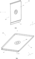
- Fig. 3 shows a schematic structural perspective view of a first component 100 having a light-transmitting portion 10 provided at step S 100 of the welding method for a household appliance 1000 according to an exemplary embodiment of the present invention.
- Fig. 4 shows a rear view of the first component 100 according to an exemplary embodiment of the present invention, as viewed in direction A in Fig. 3 , in order to better illustrate the details of the back side of the first component 100.
- the first component 100 has a first front side 101 and a first back side 102 arranged opposite the first front side 101.
- the first front side 101 is a region surface that is directly visible to the user during regular use of the household appliance 1000
- the first back side 102 is a region surface that is not directly visible to the user during regular use of the household appliance 1000.
- the light-transmitting portion 10 of the first component 100 is located at a lower portion thereof and has a depth h1.
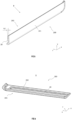
- Fig. 5 shows a schematic structural perspective view of a second component 200 having a light-absorbing portion 20 provided at step S200 of the welding method for a household appliance 1000 according to an exemplary embodiment of the present invention.
- Fig. 6 shows a rear view of the second component 200 according to an exemplary embodiment of the present invention, as viewed in direction B in Fig. 5 , in order to better illustrate the details of the back side of the second component 200.
- the second component 200 has a second front side 201 and a second back side 202 arranged opposite the second front side 201.
- the second front side 201 is a region surface that is directly visible to the user during regular use of the household appliance 1000
- the second back side 202 is a region surface that is not directly visible to the user during regular use of the household appliance 1000.
- the light-absorbing portion 20 of the first component 200 is located in the middle thereof, is configured as a protrusion (an L-shaped welding rib shown in Fig. 6 ), and has a thickness h2.
- Fig. 7 shows a schematic structural perspective view of step S300 of the welding method for a household appliance 1000 according to an exemplary embodiment of the present invention.
- Fig. 8 shows a schematic structural perspective view of step S400 of the welding method for a household appliance 1000 according to an exemplary embodiment of the present invention.
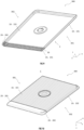
- Fig. 9 shows a schematic structural perspective view of a welded assembly 300 after performance of step S400 of the welding method for a household appliance 1000 according to an exemplary embodiment of the present invention.
- Fig. 10 shows a front view of the welded assembly according to an exemplary embodiment of the present invention, as viewed in direction C in Fig. 9 , in order to better illustrate the details of a front side of the welded assembly.
- first component 100 and the second component 200 are shown apart from each other, so that the positions of action of the welding laser 400 on the two components can be clearly seen.
- first component 100 and the second component 200 are positioned abutting against each other during actual laser welding.
- first component 100 and the second component 200 are positioned abutting against each other under the action of a clamping force F, as seen in Fig. 8 and Fig. 19(c) that is described later.
- the welded assembly 300 which is formed after performance of step S400 of the welding method for a household appliance 1000 according to an exemplary embodiment of the present invention, has an assembly front side 301 and an assembly back side 302 arranged opposite the assembly front side 301.
- the assembly front side 301 is a region surface that is directly visible to the user during regular use of the household appliance 1000
- the assembly back side 302 is a region surface that is not directly visible to the user during regular use of the household appliance 1000.
- the first front side 101 of the first component 100 and the second front side 201 of the second component 200 jointly form the assembly front side 301 of the welded assembly 300
- the first back side 102 of the first component 100 and the second back side 202 of the second component 200 jointly form the assembly back side 302 of the welded assembly 300.
- an electronic element (not shown here), which is included in the appearance member 900 having the welded assembly 300 and is configured to control the household appliance 1000, is arranged on the assembly back side 302. According to the examples in Figs.
- the assembly front side 301 of the welded assembly 300 is provided with a switch button which is convenient for the user to trigger by pressing, and the switch button is especially electrically connected to the electronic element provided on the assembly back side 302.
- the electronic element provided on the assembly back side 302 may also be understood as a circuit board or an electronic device provided with electronic elements.
- the welding portion 30 located behind the second component is just coated, so that there is no easily visible connection part on the assembly front side 301 of the welded assembly 300, thereby achieving a high-quality appearance decoration effect.
- Fig. 11 shows a schematic flowchart of sub-steps of step S100 of the welding method for a household appliance 1000 according to an exemplary embodiment of the present invention.
- Fig. 12 shows a schematic structural perspective view of the sub-steps of step S100 of the welding method for a household appliance 1000 according to an exemplary embodiment of the present invention.
- the welding method for a household appliance 1000 comprises the following sub-steps:
- the fusion of the two components will be affected during laser welding, and thus the part of the light-transmitting substrate that is not provided with the functional layer 12' is most suitable as the light-transmitting portion 10 to facilitate the implementation of laser welding.
- the integrated in-mold injection molding may be understood as in-mold decoration (IMD) or in-mold labeling (IML), in which a decorative layer or a decorative film is usually provided by means of injection molding or hot padding.
- IMD in-mold decoration
- IML in-mold labeling
- the region of the functional layer 12' is smaller than the surface region of the first base member 11, thereby achieving the effect of partially providing the functional layer 12', and the part that is not provided with the functional layer 12' forms the light-transmitting portion 10.
- Fig. 13 shows a schematic flowchart of sub-steps of step S100 of the welding method for a household appliance 1000 according to an exemplary embodiment of the present invention.
- Fig. 14 shows a schematic structural perspective view of the sub-steps of step S100 of the welding method for a household appliance 1000 according to an exemplary embodiment of the present invention.
- the welding method for a household appliance 1000 comprises the following sub-steps:
- the functional layer 12' is provided on the entirety of the surface of the first base member 11, and then the functional layer 12' in a welded region (i.e. the first welding section 110) is removed (e.g. by means of laser-etching removal), which is more in line with the actual process, because the process originally set for the in-mold injection molding machine commonly used is an injection molding process in the entirety rather than a partial injection molding process.
- this embodiment is more suitable for application based on a conventional injection molding machine without the need for excessive modification of the machinery.
- Fig. 15 shows a schematic flowchart of sub-steps of step S200 of the welding method for a household appliance 1000 according to an exemplary embodiment of the present invention.
- Fig. 16 shows a schematic structural perspective view of the sub-steps of step S200 of the welding method for a household appliance 1000 according to an exemplary embodiment of the present invention.
- the welding method for a household appliance 1000 comprises the following sub-steps:
- the electroplating layer provided in the electroplating treatment will significantly reduce the light absorption of the light-absorbing substrate and even cause reflection, which is not conducive to laser welding.
- providing an electroplating layer is necessary for both appearance and function.
- the partial electroplating treatment is used in this embodiment, especially presenting an electroplating layer on the entirety of the usage appearance region in the final application, with the region that is not electroplated being hidden on the back side of the usage appearance region and being not noticeable.
- Fig. 17 shows a schematic flowchart of sub-steps of step S200 of the welding method for a household appliance 1000 according to an exemplary embodiment of the present invention.
- Fig. 18 shows a schematic structural perspective view of the sub-steps of step S200 of the welding method for a household appliance 1000 according to an exemplary embodiment of the present invention.
- the welding method for a household appliance 1000 comprises the following sub-steps:
- the welded region (i.e. the second welding section 210) of the second base member 21 is subjected to anti-plating treatment (e.g. spraying with an anti-plating oil), and thus the effect of partial electroplating can be achieved without modification of the existing integral electroplating treatment machinery (typically, an electroplating tank).
- anti-plating treatment e.g. spraying with an anti-plating oil
- Figs. 19(a) to 19(c) show schematic structural sectional views of the steps of the welding method for a household appliance 1000 according to an exemplary embodiment of the present invention.
- the first welding section 110 of the first component 100 is configured as a recess and has a depth h1.
- the second welding section 210 of the second component 200 is configured as a protrusion, preferably an L-shaped welding rib, and has a thickness h2.
- the depth h1 is substantially consistent with the thickness h2.
- a side edge 210' of the second welding section 210 configured as the protrusion is also subjected to anti-plating treatment (preferably coated with an anti-plating layer 22).
- anti-plating treatment preferably coated with an anti-plating layer 22.
- the second welding section 210 has a process allowance (e.g. about 2 mm) around the side edge 210' during the actual anti-plating treatment, which considers the splashing and overflow of an anti-plating coating during spraying/brushing, in order to better determine the anti-plating region.
- the area of the light-transmitting portion 10 is equal to the area of the light-absorbing portion 20.
- the area of the light-transmitting portion 10 is slightly greater than the area of the light-absorbing portion 20.
- the area of the light-transmitting portion 10 is equal to, especially slightly greater than, the area of the light-absorbing portion 20, during laser welding, it is especially possible to prevent the melting and welding damage of a non-welding region (e.g. the first treatment section) of the first component due to absorption of welding laser energy by the light-absorbing part of the second component 200 that is not subjected to electroplating treatment.
- the area of the light-transmitting portion 10 especially covers the side edge (e.g. the side edge 210') of the light-absorbing portion 20, it is especially possible to ensure that the side of the light-absorbing portion 20 is also sufficiently molten during laser welding. Moreover, the case where the area of the light-transmitting portion 10 is slightly greater than the area of the light-absorbing portion 20 can especially cover up the deviation during the movement of the welding laser in the actual production process.
- the first component 100 and the second component 200 are positioned abutting against each other under the action of the clamping force F.
- the clamping force F can be understood as the clamping force F that is provided by a clamping mechanism (e.g. a fixture of a laser welding machine) having a mutual opposing effect, so that the first component 100 and the second component 200 are less prone to displacement relative to each other.
- the first front side 101 of the first component 100 is flush with the second front side 201 of the second component 200 to form an assembly front side 301 of the welded assembly 300, with the assembly front side 301 facing the user in the usage appearance region.
- the first base member 11 and/or the second base member 21 are made of a plastic material.
- the first base member 11 and/or the second base member 21 are integrally formed components.
- the first base member 11 is composed of a light-transmitting substrate that has high transmissivity (preferably complete transmission) to the welding laser 400.
- the second base member 21 is composed of a dark substrate (preferably, a black substrate) that has high absorptivity (preferably complete absorption) for the welding laser 400.
- the first base member 11 and the second base member 21 are made of different plastic materials (preferably, plastic materials having similar melting points), for example, respectively made of ABS plastic and an acrylic material.
- the first base member 11 and the second base member 21 are made of the same plastic material, for example, made of ABS plastic or an acrylic material.
- the welded assembly 300 for a household appliance 1000 comprises at least:
- the welded assembly 300 has an assembly front side 301 facing the user in the usage appearance region, and the assembly front side 301 is composed of the first front side 101 of the first component 100 and the second front side 201 of the second component 200 which are flush with each other.
- a height difference ⁇ h between the first front side 101 of the first component 100 and the second front side 201 of the second component 200 is at most 0.2 mm, preferably 0.
- a gap ⁇ d between the first front side 101 of the first component 100 and the second front side 201 of the second component 200 is at most 0.3 mm, preferably 0.
- a first base member 11 composed of a light-transmitting substrate is first provided; then a functional layer 12' is provided on a surface of the first base member 11 by means of integrated in-mold injection molding so as to form a first prefabricated member 11' having a functional region 12 on the surface of the first base member 11; and then the functional layer 12' on a first welding section 110 of the first base member 11 is removed by means of laser-etching removal with laser-etching laser 500, so as to form the first component 100 having the light-transmitting portion 10 in the first welding section 110.
- a second base member 21 composed of a light-absorbing substrate is first provided; then a second welding section 210 of the second base member 21 is coated with an anti-plating layer 22 so as to form a second prefabricated member 21' having an anti-plating region 22 in the second welding section 210; and then electroplating is performed on the entirety of the second base member 21 such that the surface of the second base member 21 is coated with an electroplating layer 23 except for the second welding section 210 to form the second component 200 having the light-absorbing portion 20 in the second welding section 210.
- the first component 100 and the second component 200 are positioned abutting against each other under the action of a clamping force F such that the light-transmitting portion 10 of the first component 100 and the light-absorbing portion 20 of the second component 200 have an overlapping region 50; and then the welding laser 400 is directed onto the light-absorbing portion 20 through the light-transmitting portion 10 in the overlapping region 50 to form a welding portion 30 between the light-transmitting portion 10 and the light-absorbing portion 20, so that the first component 100 and the second component 200 are welded together to form a welded assembly 300, the welded assembly 300 forming a usage appearance region of the household appliance 1000, with the welding portion 30 being hidden in the usage appearance region.
Landscapes
- Engineering & Computer Science (AREA)
- Mechanical Engineering (AREA)
- Physics & Mathematics (AREA)
- Optics & Photonics (AREA)
- Plasma & Fusion (AREA)
- Health & Medical Sciences (AREA)
- Electromagnetism (AREA)
- Toxicology (AREA)
- Lining Or Joining Of Plastics Or The Like (AREA)
Abstract
Description
- The present invention relates to the field of household appliances, in particular to a welding method for a household appliance, a welded assembly for a household appliance, an appearance member for a household appliance, and a corresponding household appliance.
- With the improvement of living standards, people have increasingly higher demands on the appearance of household appliances.
- When an appearance region of a household appliance is manufactured, it is usually necessary to connect at least two different components together to form at least a portion of the appearance region of the household appliance.
- In the prior art, snap-fit connection or adhesive bonding is usually used in such a connecting process, but neither the snap-fit connection nor the adhesive bonding is a permanent connection, that is, the two different components connected together by means of such process may age or even come off over time, resulting in failure of the connection.
- On the other hand, people also do not want to see that there is a noticeable connection part (such as the aforementioned snap-fit connection or adhesive bonding part) in the appearance region of the household appliance during regular use of the household appliance, because such noticeable connection part would make a user think that the household appliance has a low-quality and cheap appearance.
- Therefore, there is still a need for continuous improvement in the manufacturing technology of the appearance region of existing household appliances.
- An object of the embodiments of the present invention is to provide an improved welding method for a household appliance, an improved welded assembly, an improved appearance member for a household appliance and an improved household appliance, so as to solve at least some of the problems in the prior art.
- According to a first aspect of the present invention, the embodiments of the present invention provide a welding method for a household appliance, the welding method comprising at least:
- step S100 of providing a first component having a light-transmitting portion;
- step S200 of providing a second component having a light-absorbing portion;
- step S300 of positioning the first component and the second component relative to each other such that the light-transmitting portion and the light-absorbing portion have an overlapping region; and
- step S400 of directing a welding laser onto the light-absorbing portion through the light-transmitting portion in the overlapping region to form a welding portion between the light-transmitting portion and the light-absorbing portion, so that the first component and the second component are welded together to form a welded assembly, wherein the welded assembly forms a usage appearance region of the household appliance, with the welding portion being hidden in the usage appearance region.
- In this way, on the one hand, compared with the snap-fit connection or adhesive bonding in the prior art, the welding connection allows the two connected components to have higher connection strength and be less prone to aging and detachment; on the other hand, the welding portion that connects the two components together is hidden in the usage appearance region of the household appliance, which not only achieves permanent connection of the two components, but also makes the welding portion that connects the two components together less visible to a user during regular use of the household appliance, so that the household appliance is durable and has a high-quality decorative appearance effect.
- According to an optional embodiment of the present invention, the welding method comprises:
- step S101 of providing a first base member composed of a light-transmitting substrate; and
- step S102 of carrying out partial process treatment (preferably by means of partial integrated in-mold injection molding) on the first base member to provide a functional layer (in particular an ink layer and/or a UV protective layer) so as to form a first component having a light-transmitting portion in the part that is not provided with the functional layer.
- In this way, the first base member composed of the light-transmitting substrate is used, so that the welding method provided in the embodiment of the present invention is feasible, and thus the appearance member provided with a functional layer, which is not easily connected by laser welding, is connected by welding using the welding method provided in the embodiment of the present invention, thereby overcoming the problems, such as easy aging and detachment, of the appearance member provided with the functional layer caused by the snap-fit connection or adhesive bonding manner commonly used for an appearance member provided with a functional layer in the prior art.
- According to an optional embodiment of the present invention, the welding method comprises:
- step S201 of providing a second base member composed of a light-absorbing substrate; and
- step S202 of carrying out partial electroplating treatment on the second base member to form the second component having the light-absorbing portion in the part that is not subjected to electroplating treatment.
- In this way, the second base member composed of the light-absorbing substrate is used, so that the welding method provided in the embodiment of the present invention is feasible, and thus the electroplated appearance member, which is not easily connected by laser welding, is connected by welding using the welding method provided in the embodiment of the present invention, thereby overcoming the problems, such as easy aging and detachment, of the electroplated appearance member caused by the snap-fit connection or adhesive bonding manner commonly used for an electroplated appearance member in the prior art.
- According to an optional embodiment of the present invention, the welding method comprises:
-
step S 111 of providing a first base member composed of a light-transmitting substrate, wherein a surface of the first base member has a first welding section and a first treatment section; - step S112 of carrying out process treatment (preferably by means of integrated in-mold injection molding) on the first welding section and the first treatment section to provide a functional layer (in particular an ink layer and/or a UV protective layer) so as to form a first prefabricated member having a functional region in the first welding section and the first treatment section; and
- step S113 of stripping the functional layer from the first welding section, preferably by means of laser-etching removal with a laser-etching laser, so as to form the first component having a light-transmitting portion in the first welding section.
- In this way, the functional layer is provided on the entirety of the surface of the first base member composed of the light-transmitting substrate, and then part of the functional layer is removed by means of the laser-etching laser, which not only simplifies the manufacturing process (because providing the functional layer in the entirety is easier than partially providing the functional layer), but also ensures the light transmission of the part where the functional layer is removed, because the laser-etching laser can remove the functional layer more completely as compared with other removal techniques such that there is no remaining functional layer affecting the fusion of the two components during laser welding.
- According to an optional embodiment of the present invention, the welding method comprises:
- step S211 of providing the second base member composed of the light-absorbing substrate, wherein a surface of the second base member has a second welding section and a second treatment section;
- step S212 of carrying out anti-plating treatment on the second welding section, preferably coating with an anti-plating layer, so as to form a second prefabricated member having an anti-plating region in the second welding section;
- step S213 of electroplating the entirety of the second base member such that the surface of the second base member is coated with an electroplating layer except for the second welding section to form the second component having the light-absorbing portion in the second welding section.
- In this way, the second base member composed of the light-absorbing substrate is first provided with the anti-plating region and then subjected to electroplating treatment in the entirety, which not only simplifies the manufacturing process (because the electroplating treatment in the entirety is simpler than the partial electroplating treatment), but also ensures that the anti-plating region is not affected by the electroplating treatment, so that the anti-plating region absorbs the welding laser as completely as possible during laser welding, thereby ensuring the fusion of the two components during laser welding.
- According to an optional embodiment of the present invention, the first welding section is configured as a recess and has a depth. In this way, the first welding section having the recess is easier to cover than another pair of welding components, which is convenient to hide the originally visible welding portion.
- According to an optional embodiment of the present invention, the second welding section is configured as a protrusion, preferably an L-shaped welding rib, and has a thickness. In this way, the second welding section configured as a protrusion, preferably an L-shaped welding rib, is easier to align during laser welding and is also easier to fit with another pair of welding components.
- According to an optional embodiment of the present invention, the depth is substantially consistent with the thickness. In this way, in the case where the depth of the first welding section configured as a recess is consistent with the thickness of the second welding section configured as a protrusion, preferably an L-shaped welding rib, the first component having the first welding section can fit flush with the second component having the second welding section, which is more conducive to a high-quality appearance effect.
- According to an optional embodiment of the present invention, in step S212, a side edge of the second welding section configured as a protrusion is also subjected to anti-plating treatment, preferably coated with an anti-plating layer. In this way, it is ensured that the side edge of the second welding section also fully absorbs the welding laser during laser welding, thereby achieving more complete fusion of the two components.
- According to an optional embodiment of the present invention, the area of the light-transmitting portion is equal to the area of the light-absorbing portion, preferably, the area of the light-transmitting portion is greater than the area of the light-absorbing portion. This avoids the melting and welding damage of part of the non-welding region of the first component caused by the welding laser being accidentally absorbed by the functional layer region during laser welding.
- According to an optional embodiment of the present invention, the first component and the second component are positioned abutting against each other under the action of a clamping force. This further ensures that the laser welding occurs between the light-transmitting portion of the first component and the light-absorbing portion of the second component without accidental displacement.
- According to an optional embodiment of the present invention, a first front side of the first component is flush with a second front side of the second component to form an assembly front side of the welded assembly, wherein the assembly front side faces a user in the usage appearance region. In this way, in the eyes of the user, there is no uneven and low-quality appearance decoration effect in the appearance region of the household appliance, thereby improving the use experience of the user.
- According to an optional embodiment of the present invention, the first base member and/or the second base member are made of a plastic material. This makes it easier to achieve fusion of the two components by means of the welding laser.
- According to an optional embodiment of the present invention, the first base member and/or the second base member are integrally formed components. This simplifies the process and reduces the number of components.
- According to an optional embodiment of the present invention, the first base member is composed of a light-transmitting substrate that has high transmissivity, preferably complete transmission, to the welding laser. This makes it easier for the first component to allow transmission of the welding laser during laser welding, avoiding unnecessary laser loss.
- According to an optional embodiment of the present invention, the second base member is composed of a dark substrate, preferably a black substrate, which has high absorptivity, preferably complete absorption, for the welding laser. This makes it easier for the second component to absorb the welding laser during laser welding, avoiding unnecessary laser loss.
- According to an optional embodiment of the present invention, the first base member and the second base member are made of different plastic materials, preferably plastic materials having similar melting points, for example, respectively made of ABS plastic and an acrylic material. This enables laser welding between different plastic materials, because the plastic materials having similar melting points are more conducive to achieving fusion between the two components.
- According to an optional embodiment of the present invention, the first base member and the second base member are made of the same plastic material, for example, made of ABS plastic or an acrylic material. In this way, the two components made of the same plastic material are further conducive to fusion of the components.
- According to a second aspect of the present invention, the embodiments of the present invention provide a welded assembly for a household appliance, the welded assembly comprising at least:
- a first component and a second component, and
- a welding portion between the first component and the second component, the welded assembly forming a usage appearance region of the household appliance, with the welding portion being hidden in the usage appearance region,
- wherein the welded assembly is manufactured by means of the welding method according to the embodiments in the first aspect of the present invention.
- In this way, such a welded assembly has at least the advantages mentioned in the first aspect described above that the household appliance has a high-quality decorative appearance effect and that the two connected components are less prone to aging and detachment.
- According to an optional embodiment of the present invention, the welded assembly has an assembly front side facing a user in the usage appearance region, and the assembly front side is composed of a first front side of the first component and a second front side of the second component which are flush with each other.
- In this way, in the eyes of the user, there is no uneven and low-quality appearance decoration effect in the appearance region of the household appliance, thereby improving the use experience of the user.
- According to an optional embodiment of the present invention, in the assembly front side, a height difference between the first front side of the first component and the second front side of the second component is at most 0.2 mm, preferably 0. This achieves a nearly completely smooth transition between the two components in the assembly front side.
- According to an optional embodiment of the present invention, in the assembly front side, a gap between the first front side of the first component and the second front side of the second component is at most 0.3 mm, preferably 0. This achieves a nearly no-gap transition between the two components in the assembly front side.
- According to a third aspect of the present invention, the embodiments of the present invention provide an appearance member for a household appliance, the appearance member comprising a welded assembly according to the embodiments in the second aspect of the present invention. In this way, such an appearance member has at least the advantages mentioned in the second aspect described above that the household appliance has a high-quality decorative appearance effect and that the two connected components are less prone to aging and detachment.
- According to an optional embodiment of the present invention, the appearance member further comprises electronic elements that are arranged on an assembly back side of the welded assembly facing away from the user and are configured to control the household appliance. In this way, by means of the welding method according to the embodiments of the present invention, these electronic elements can be well-protected on the assembly back side, especially achieving a waterproof function.
- According to an optional embodiment of the present invention, the appearance member is a control panel. In this way, by means of the welding method according to the embodiments of the present invention, the control panel of a household appliance avoids the problems, such as aging and detachment, of the connection parts of the component while achieving the high-quality appearance effect.
- According to an optional embodiment of the present invention, the appearance member is a door ring of a washing machine. In this way, by means of the welding method according to the embodiments of the present invention, the door ring of a washing machine avoids the problems, such as aging and detachment, of the connection parts of the components while achieving the high-quality appearance effect.
- According to a fourth aspect of the present invention, the embodiments of the present invention provide a household appliance, comprising a welded assembly according to the embodiments in the second aspect of the present invention and/or an appearance member according to the embodiments in the third aspect of the present invention. In this way, such a household appliance has at least the advantages mentioned in the second aspect and/or in the third aspect described above that the household appliance has a high-quality decorative appearance effect and that the two connected components are less prone to aging and detachment.
- According to an optional embodiment of the present invention, the household appliance is a water-guided household appliance. In this way, by means of the welding method according to the embodiments of the present invention, the water-guided household appliance avoids the problems, such as aging and detachment, of the connection parts of the components, especially achieving a waterproof function for the electronic elements arranged near the welding part, while achieving the high-quality appearance effect.
- According to an optional embodiment of the present invention, the household appliance is a washing machine, a dishwasher, or an electric coffee maker. In this way, by means of the welding method according to the embodiments of the present invention, the household appliance such as a washing machine, a dishwasher or an electric coffee maker avoids the problems, such as aging and detachment, of the connection parts of the components while achieving the high-quality appearance effect.
- In the following, the principles, features and advantages of the present invention can be better understood by describing the present invention in more detail with reference to the accompanying drawings. In the drawings:
-
Fig. 1 shows a schematic flowchart of a welding method for a household appliance according to an exemplary embodiment of the present invention; -
Fig. 2 shows a schematic diagram of a household appliance according to an exemplary embodiment of the present invention; -
Fig. 3 shows a schematic structural perspective view of a first component having a light-transmitting portion provided at step S100 of the welding method for a household appliance according to an exemplary embodiment of the present invention; -
Fig. 4 shows a rear view of the first component according to an exemplary embodiment of the present invention, as viewed in direction A inFig. 3 , in order to better illustrate the details of a back side of the first component; -
Fig. 5 shows a schematic structural perspective view of a second component having a light-absorbing portion provided at step S200 of the welding method for a household appliance according to an exemplary embodiment of the present invention; -
Fig. 6 shows a rear view of the second component according to an exemplary embodiment of the present invention, as viewed in direction B inFig. 5 , in order to better illustrate the details of the back side of the second component; -
Fig. 7 shows a schematic structural perspective view of step S300 of the welding method for a household appliance according to an exemplary embodiment of the present invention; -
Fig. 8 shows a schematic structural perspective view of step S400 of the welding method for a household appliance according to an exemplary embodiment of the present invention; -
Fig. 9 shows a schematic structural perspective view of a welded assembly formed after performance of step S400 of the welding method for a household appliance according to an exemplary embodiment of the present invention; -
Fig. 10 shows a front view of the welded assembly according to an exemplary embodiment of the present invention, as viewed in direction C inFig. 9 , in order to better illustrate the details of a front side of the welded assembly; -
Fig. 11 shows a schematic flowchart of sub-steps of step S100 of the welding method for a household appliance according to an exemplary embodiment of the present invention; -
Fig. 12 shows a schematic structural perspective view of the sub-steps of step S100 of the welding method for a household appliance according to an exemplary embodiment of the present invention; -
Fig. 13 shows a schematic flowchart of sub-steps of step S100 of the welding method for a household appliance according to an exemplary embodiment of the present invention; -
Fig. 14 shows a schematic structural perspective view of the sub-steps of step S100 of the welding method for a household appliance according to an exemplary embodiment of the present invention; -
Fig. 15 shows a schematic flowchart of sub-steps of step S200 of the welding method for a household appliance according to an exemplary embodiment of the present invention; -
Fig. 16 shows a schematic structural perspective view of the sub-steps of step S200 of the welding method for a household appliance according to an exemplary embodiment of the present invention; -
Fig. 17 shows a schematic flowchart of sub-steps of step S200 of the welding method for a household appliance according to an exemplary embodiment of the present invention; -
Fig. 18 shows a schematic structural perspective view of the sub-steps of step S200 of the welding method for a household appliance according to an exemplary embodiment of the present invention; and -
Figs. 19(a) to 19(c) show schematic structural sectional views of the steps of the welding method for a household appliance according to an exemplary embodiment of the present invention. - Embodiments of the present invention will be described in detail below, and exemplary embodiments are shown in the drawings, with the same or similar reference numerals throughout the drawings representing the same or similar elements or the elements having the same or similar functions. The embodiments described below with reference to the accompanying drawings are exemplary and are intended to be illustrative of the present invention, and will not be interpreted as limiting the present invention.
- In the description of the present invention, it should be understood that the orientations or position relationships indicated by the terms, such as "upper", "lower", "front", "rear", "left", "right", "vertical", "horizontal", "top", "bottom", "inner", "outer", "longitudinal", "transverse", "high", "front side", or "back side", are based on the orientations or position relationships shown in the accompanying drawings and are merely for ease of description of the present invention and simplification of the description, rather than indicating or implying that the devices or elements referred to necessarily have specific orientations or are configured and operated in specific orientations, and thus cannot be construed as limiting the present invention.
- In addition, the expression "A and/or B" denotes all possible combinations of A and B, such as A only, B only, or both A and B. The expression "at least one A or B" or "at least one of A and B" has a similar meaning as "A and/or B", and may include A only, B only, or both A and B. The terms "first" and "second" are intended for descriptive purposes only and should not be construed as indicating or implying relative importance or implicitly indicating the number of technical features indicated. Thus, the features defined with "first" and "second" may explicitly or implicitly include one or more features. In the description of the present invention, the expression "a plurality of" means two or more, unless explicitly and specifically defined otherwise.
- The exemplary embodiments of the present invention will be described below with respect to the accompanying drawings.
-
Fig. 1 is a schematic flowchart of a welding method for ahousehold appliance 1000 according to an exemplary embodiment of the present invention. As shown inFig. 1 , the welding method for ahousehold appliance 1000 according to an exemplary embodiment of the present invention comprises at least: - step S100 of providing a
first component 100 having a light-transmittingportion 10; - step S200 of providing a
second component 200 having a light-absorbingportion 20; - step S300 of positioning the
first component 100 and thesecond component 200 relative to each other such that the light-transmittingportion 10 and the light-absorbingportion 20 have anoverlapping region 50; and - step S400 of directing
welding laser 400 onto the light-absorbingportion 20 through the light-transmittingportion 10 in the overlappingregion 50 to form awelding portion 30 between the light-transmittingportion 10 and the light-absorbingportion 20, so that thefirst component 100 and thesecond component 200 are welded together to form a weldedassembly 300, wherein the weldedassembly 300 forms a usage appearance region of thehousehold appliance 1000, with thewelding portion 30 being hidden in the usage appearance region. - It should be noted that, within the scope of the present invention, the term "usage appearance region" should particularly be understood as an appearance region that directly faces a user during regular use of the
household appliance 1000 by the user, or an appearance region that is directly visible to the user during regular use of thehousehold appliance 1000. - Here, the selection of parameters of the
welding laser 400 is dependent on specific applications, such as the material and the fusion area, of the two components. Optionally, thewelding laser 400 has a laser wavelength in a range from 900 µm to 1000 µm, and a laser power in a range from 5 W to 20 W. The selection range of parameters of thewelding laser 400 is particularly conducive to implementing the welding method provided in the embodiment of the present invention. - The
household appliance 1000 and the constituent parts for implementing the welding method should be particularly understood with reference to the embodiments that will be described below with respect to the figures. -
Fig. 2 shows a schematic diagram of ahousehold appliance 1000 according to an exemplary embodiment of the present invention. InFig. 2 , thehousehold appliance 1000 is shown as a washing machine. It should be understood that thehousehold appliance 1000 can also be configured as a household appliance in another form, in particular a water-guided household appliance, such as a dishwasher or an electric coffee maker, etc. - According to an exemplary embodiment of the present invention, as also shown in
Fig. 2 , thehousehold appliance 1000 comprises an appearance member 900. Exemplarily, the appearance member 900 is configured as a control panel 910 and/or a door ring 920 of a washing machine, because the control panel 910 and the door ring 920 of the washing machine generally comprise electronic elements or electronic sensors and are generally configured by connection of two or more components, and thus are especially applicable for the welding method according to the embodiment of the present invention. For the door ring 920 of the washing machine, by means of the welding method provided in the embodiment of the present invention, the fusion of a display screen and a door cover plate can be achieved, and in the case of using integrated in-mold injection molding, the display screen can be hidden in the door cover plate when the display screen is turned off, for example, showing a one-piece black decoration effect, thereby achieving a high-quality appearance effect. - According to an exemplary embodiment of the present invention, the appearance member 900 for the
household appliance 1000 comprises a weldedassembly 300 manufactured according to the steps of the method inFig. 1, and Fig. 2 schematically shows the weldedassembly 300 as a portion of the appearance member 900 configured as the control panel 910. - According to an exemplary embodiment of the present invention, the appearance member 900 further comprises electronic elements (not shown here) which are arranged on an assembly back
side 302 of the weldedassembly 300 facing away from the user and are configured to control thehousehold appliance 1000. Exemplarily, the electronic elements here involve switch circuits that can trigger the start and stop of thehousehold appliance 1000, and the electronic elements or switch circuits are electrically connected to switch buttons schematically shown inFig. 2 and the subsequent figures. In general, the electronic elements or switch circuits need to be attached to a rear surface of the control panel, and based on the conventional safety requirements of household appliances, it is necessary to ensure that the components covering the electronic elements or switch circuits will not age or come off. -
Fig. 2 further shows a width direction x, a height direction y and a depth direction z of thehousehold appliance 1000 as a washing machine in a regular use state. For clarity, the subsequent figures also use the xyz rectangular coordinate system shown inFig. 2 . In other words, the corresponding orientations of the constituent parts of the weldedassembly 300 that form thehousehold appliance 1000 are shown in the subsequent figures based on the xyz rectangular coordinate system shown inFig. 2 , in order to better illustrate a front side (i.e. a region surface of the finally formedhousehold appliance 1000 that is directly visible to the user during regular use) of the constituent parts and a back side (i.e. a region surface of the finally formedhousehold appliance 1000 that is not directly visible to the user during regular use) arranged opposite the front side. -
Fig. 3 shows a schematic structural perspective view of afirst component 100 having a light-transmittingportion 10 provided at step S 100 of the welding method for ahousehold appliance 1000 according to an exemplary embodiment of the present invention.Fig. 4 shows a rear view of thefirst component 100 according to an exemplary embodiment of the present invention, as viewed in direction A inFig. 3 , in order to better illustrate the details of the back side of thefirst component 100. - As shown in
Figs. 3 and 4 , according to an exemplary embodiment of the present invention, thefirst component 100 has a firstfront side 101 and a firstback side 102 arranged opposite the firstfront side 101. Here, the firstfront side 101 is a region surface that is directly visible to the user during regular use of thehousehold appliance 1000, and the firstback side 102 is a region surface that is not directly visible to the user during regular use of thehousehold appliance 1000. Here, exemplarily, the light-transmittingportion 10 of thefirst component 100 is located at a lower portion thereof and has a depth h1. -
Fig. 5 shows a schematic structural perspective view of asecond component 200 having a light-absorbingportion 20 provided at step S200 of the welding method for ahousehold appliance 1000 according to an exemplary embodiment of the present invention.Fig. 6 shows a rear view of thesecond component 200 according to an exemplary embodiment of the present invention, as viewed in direction B inFig. 5 , in order to better illustrate the details of the back side of thesecond component 200. - As shown in
Figs. 5 and 6 , thesecond component 200 according to an exemplary embodiment of the present invention has a secondfront side 201 and a secondback side 202 arranged opposite the secondfront side 201. Here, the secondfront side 201 is a region surface that is directly visible to the user during regular use of thehousehold appliance 1000, and the secondback side 202 is a region surface that is not directly visible to the user during regular use of thehousehold appliance 1000. Here, exemplarily, the light-absorbingportion 20 of thefirst component 200 is located in the middle thereof, is configured as a protrusion (an L-shaped welding rib shown inFig. 6 ), and has a thickness h2. -
Fig. 7 shows a schematic structural perspective view of step S300 of the welding method for ahousehold appliance 1000 according to an exemplary embodiment of the present invention.Fig. 8 shows a schematic structural perspective view of step S400 of the welding method for ahousehold appliance 1000 according to an exemplary embodiment of the present invention.Fig. 9 shows a schematic structural perspective view of a weldedassembly 300 after performance of step S400 of the welding method for ahousehold appliance 1000 according to an exemplary embodiment of the present invention.Fig. 10 shows a front view of the welded assembly according to an exemplary embodiment of the present invention, as viewed in direction C inFig. 9 , in order to better illustrate the details of a front side of the welded assembly. - Here, for ease of understanding, in
Figs. 7 and 8 , thefirst component 100 and thesecond component 200 are shown apart from each other, so that the positions of action of thewelding laser 400 on the two components can be clearly seen. However, it should be understood that thefirst component 100 and thesecond component 200 are positioned abutting against each other during actual laser welding. Optionally, thefirst component 100 and thesecond component 200 are positioned abutting against each other under the action of a clamping force F, as seen inFig. 8 andFig. 19(c) that is described later. - As shown in
Figs. 7 to 10 , particularly with reference toFigs. 9 and 10 , the weldedassembly 300, which is formed after performance of step S400 of the welding method for ahousehold appliance 1000 according to an exemplary embodiment of the present invention, has anassembly front side 301 and an assembly backside 302 arranged opposite theassembly front side 301. Here, theassembly front side 301 is a region surface that is directly visible to the user during regular use of thehousehold appliance 1000, and the assembly backside 302 is a region surface that is not directly visible to the user during regular use of thehousehold appliance 1000. With respect toFigs. 3 to 6 , in the weldedassembly 300 formed after performance of step S400, the firstfront side 101 of thefirst component 100 and the secondfront side 201 of thesecond component 200 jointly form theassembly front side 301 of the weldedassembly 300, and the firstback side 102 of thefirst component 100 and the secondback side 202 of thesecond component 200 jointly form the assembly backside 302 of the weldedassembly 300. With respect toFig. 2 , an electronic element (not shown here), which is included in the appearance member 900 having the weldedassembly 300 and is configured to control thehousehold appliance 1000, is arranged on the assembly backside 302. According to the examples inFigs. 9 and 10 , theassembly front side 301 of the weldedassembly 300 is provided with a switch button which is convenient for the user to trigger by pressing, and the switch button is especially electrically connected to the electronic element provided on the assembly backside 302. Here, the electronic element provided on the assembly backside 302 may also be understood as a circuit board or an electronic device provided with electronic elements. In particular, based on the example inFig. 10 , since the secondfront side 201 of thesecond component 200 is an electroplated opaque surface, thewelding portion 30 located behind the second component is just coated, so that there is no easily visible connection part on theassembly front side 301 of the weldedassembly 300, thereby achieving a high-quality appearance decoration effect. -
Fig. 11 shows a schematic flowchart of sub-steps of step S100 of the welding method for ahousehold appliance 1000 according to an exemplary embodiment of the present invention.Fig. 12 shows a schematic structural perspective view of the sub-steps of step S100 of the welding method for ahousehold appliance 1000 according to an exemplary embodiment of the present invention. - As shown in
Figs. 11 and 12 , the welding method for ahousehold appliance 1000 according to an exemplary embodiment of the present invention (more specifically, step S100 of the welding method) comprises the following sub-steps: - step S101 of providing a
first base member 11 composed of a light-transmitting substrate; and - step S102 of carrying out partial process treatment (preferably by means of partial integrated in-mold injection molding) on the
first base member 11 to provide a functional layer 12' (in particular an ink layer and/or a UV protective layer) so as to form afirst component 100 having a light-transmittingportion 10 in the part that is not provided with the functional layer 12'. - For the functional layer 12', whether it is the colored ink layer or the UV protective layer that looks transparent, the fusion of the two components will be affected during laser welding, and thus the part of the light-transmitting substrate that is not provided with the functional layer 12' is most suitable as the light-transmitting
portion 10 to facilitate the implementation of laser welding. - Within the scope of the present invention, the integrated in-mold injection molding may be understood as in-mold decoration (IMD) or in-mold labeling (IML), in which a decorative layer or a decorative film is usually provided by means of injection molding or hot padding.
- As schematically shown in
Fig. 12 , the region of the functional layer 12' is smaller than the surface region of thefirst base member 11, thereby achieving the effect of partially providing the functional layer 12', and the part that is not provided with the functional layer 12' forms the light-transmittingportion 10. -
Fig. 13 shows a schematic flowchart of sub-steps of step S100 of the welding method for ahousehold appliance 1000 according to an exemplary embodiment of the present invention.Fig. 14 shows a schematic structural perspective view of the sub-steps of step S100 of the welding method for ahousehold appliance 1000 according to an exemplary embodiment of the present invention. - As shown in
Figs. 13 and14 , the welding method for ahousehold appliance 1000 according to an exemplary embodiment of the present invention (more specifically, step S100 of the welding method) comprises the following sub-steps: - step 5111 of providing a
first base member 11 composed of a light-transmitting substrate, with a surface of thefirst base member 11 having afirst welding section 110 and afirst treatment section 120; - step S112 of carrying out process treatment (preferably by means of integrated in-mold injection molding) on the
first welding section 110 and thefirst treatment section 120 to provide the functional layer 12' (in particular the ink layer and/or the UV protective layer) so as to form a first prefabricated member 11' having afunctional region 12 in thefirst welding section 110 and thefirst treatment section 120; and - step S113 of stripping the functional layer 12' from the first welding section 110 (preferably by means of laser-etching removal with laser-etching laser 500) so as to form the
first component 100 having the light-transmittingportion 10 in thefirst welding section 110. - In this embodiment, the functional layer 12' is provided on the entirety of the surface of the
first base member 11, and then the functional layer 12' in a welded region (i.e. the first welding section 110) is removed (e.g. by means of laser-etching removal), which is more in line with the actual process, because the process originally set for the in-mold injection molding machine commonly used is an injection molding process in the entirety rather than a partial injection molding process. Thus, this embodiment is more suitable for application based on a conventional injection molding machine without the need for excessive modification of the machinery. -
Fig. 15 shows a schematic flowchart of sub-steps of step S200 of the welding method for ahousehold appliance 1000 according to an exemplary embodiment of the present invention.Fig. 16 shows a schematic structural perspective view of the sub-steps of step S200 of the welding method for ahousehold appliance 1000 according to an exemplary embodiment of the present invention. - As shown in
Figs. 15 and 16 , the welding method for ahousehold appliance 1000 according to an exemplary embodiment of the present invention (more specifically, step S200 of the welding method) comprises the following sub-steps: - step S201 of providing a
second base member 21 composed of a light-absorbing substrate; and - step S202 of carrying out partial electroplating treatment on the
second base member 21 to form thesecond component 200 having the light-absorbingportion 20 in the part that is not subjected to electroplating treatment. - Here, the electroplating layer provided in the electroplating treatment will significantly reduce the light absorption of the light-absorbing substrate and even cause reflection, which is not conducive to laser welding. However, for household appliances, providing an electroplating layer is necessary for both appearance and function. Thus, in order to further facilitate the implementation of the welding method provided in the embodiment of the present invention, the partial electroplating treatment is used in this embodiment, especially presenting an electroplating layer on the entirety of the usage appearance region in the final application, with the region that is not electroplated being hidden on the back side of the usage appearance region and being not noticeable.
-
Fig. 17 shows a schematic flowchart of sub-steps of step S200 of the welding method for ahousehold appliance 1000 according to an exemplary embodiment of the present invention.Fig. 18 shows a schematic structural perspective view of the sub-steps of step S200 of the welding method for ahousehold appliance 1000 according to an exemplary embodiment of the present invention. - As shown in
Figs. 17 and 18 , the welding method for ahousehold appliance 1000 according to an exemplary embodiment of the present invention (more specifically, step S200 of the welding method) comprises the following sub-steps: - step S211 of providing the
second base member 21 composed of the light-absorbing substrate, with a surface of thesecond base member 21 having asecond welding section 210 and asecond treatment section 220; - step S212 of carrying out anti-plating treatment on the second welding section 210 (preferably by means of coating with an anti-plating layer 22) so as to form a second prefabricated member 21' having an
anti-plating region 22 in thesecond welding section 210; and - step S213 of electroplating the entirety of the second base member 21 (in particular, as schematically shown in
Fig. 18 , immersing the entirety of thesecond base member 21 in an electroplating tank for electroplating) such that the surface of thesecond base member 21 is coated with anelectroplating layer 23 except for thesecond welding section 210 to form thesecond component 200 having the light-absorbingportion 20 in thesecond welding section 210. - In this embodiment, before the regular electroplating treatment, the welded region (i.e. the second welding section 210) of the
second base member 21 is subjected to anti-plating treatment (e.g. spraying with an anti-plating oil), and thus the effect of partial electroplating can be achieved without modification of the existing integral electroplating treatment machinery (typically, an electroplating tank). -
Figs. 19(a) to 19(c) show schematic structural sectional views of the steps of the welding method for ahousehold appliance 1000 according to an exemplary embodiment of the present invention. - According to an exemplary embodiment of the present invention, as shown in
Fig. 19(a) and also with respect toFig. 4 , thefirst welding section 110 of thefirst component 100 is configured as a recess and has a depth h1. - According to an exemplary embodiment of the present invention, as shown in
Fig. 19(b) and also with respect toFigs. 5 and 6 , thesecond welding section 210 of thesecond component 200 is configured as a protrusion, preferably an L-shaped welding rib, and has a thickness h2. - According to an exemplary embodiment of the present invention, the depth h1 is substantially consistent with the thickness h2.
- According to an exemplary embodiment of the present invention, as shown in
Fig. 19(b) and also with respect toFigs. 17 and 18 , in step S212, a side edge 210' of thesecond welding section 210 configured as the protrusion is also subjected to anti-plating treatment (preferably coated with an anti-plating layer 22). In addition to the side edge 210' as schematically shown inFig. 19(b) , thesecond welding section 210 has a process allowance (e.g. about 2 mm) around the side edge 210' during the actual anti-plating treatment, which considers the splashing and overflow of an anti-plating coating during spraying/brushing, in order to better determine the anti-plating region. - According to an exemplary embodiment of the present invention, the area of the light-transmitting
portion 10 is equal to the area of the light-absorbingportion 20. Optionally, as also shown inFig. 19(c) , the area of the light-transmittingportion 10 is slightly greater than the area of the light-absorbingportion 20. In the case where the area of the light-transmittingportion 10 is equal to, especially slightly greater than, the area of the light-absorbingportion 20, during laser welding, it is especially possible to prevent the melting and welding damage of a non-welding region (e.g. the first treatment section) of the first component due to absorption of welding laser energy by the light-absorbing part of thesecond component 200 that is not subjected to electroplating treatment. In the case where the area of the light-transmittingportion 10 especially covers the side edge (e.g. the side edge 210') of the light-absorbingportion 20, it is especially possible to ensure that the side of the light-absorbingportion 20 is also sufficiently molten during laser welding. Moreover, the case where the area of the light-transmittingportion 10 is slightly greater than the area of the light-absorbingportion 20 can especially cover up the deviation during the movement of the welding laser in the actual production process. - According to an exemplary embodiment of the present invention, as shown in
Fig. 19(c) and also with respect toFig. 8 , thefirst component 100 and thesecond component 200 are positioned abutting against each other under the action of the clamping force F. Here, the clamping force F can be understood as the clamping force F that is provided by a clamping mechanism (e.g. a fixture of a laser welding machine) having a mutual opposing effect, so that thefirst component 100 and thesecond component 200 are less prone to displacement relative to each other. - According to an exemplary embodiment of the present invention, as shown in
Fig. 19(c) and also with respect toFig. 10 , the firstfront side 101 of thefirst component 100 is flush with the secondfront side 201 of thesecond component 200 to form anassembly front side 301 of the weldedassembly 300, with theassembly front side 301 facing the user in the usage appearance region. - According to an exemplary embodiment of the present invention, as shown in
Figs. 19(a) and19(b) , thefirst base member 11 and/or thesecond base member 21 are made of a plastic material. - According to an exemplary embodiment of the present invention, as shown in
Figs. 19(a) and19(b) , thefirst base member 11 and/or thesecond base member 21 are integrally formed components. - According to an exemplary embodiment of the present invention, as shown in
Fig. 19(a) , thefirst base member 11 is composed of a light-transmitting substrate that has high transmissivity (preferably complete transmission) to thewelding laser 400. - According to an exemplary embodiment of the present invention, as shown in
Fig. 19(b) , thesecond base member 21 is composed of a dark substrate (preferably, a black substrate) that has high absorptivity (preferably complete absorption) for thewelding laser 400. - According to an exemplary embodiment of the present invention, as shown in
Figs. 19(a) and19(b) , thefirst base member 11 and thesecond base member 21 are made of different plastic materials (preferably, plastic materials having similar melting points), for example, respectively made of ABS plastic and an acrylic material. - According to an exemplary embodiment of the present invention, as shown in
Figs. 19(a) and19(b) , thefirst base member 11 and thesecond base member 21 are made of the same plastic material, for example, made of ABS plastic or an acrylic material. - As shown in
Fig. 19(c) and also with respect toFigs. 9 and 10 , the weldedassembly 300 for ahousehold appliance 1000 according to an exemplary embodiment of the present invention comprises at least: - a
first component 100 and asecond component 200, and - a
welding portion 30 between thefirst component 100 and thesecond component 200, the weldedassembly 300 forming a usage appearance region of thehousehold appliance 1000, with thewelding portion 30 being hidden in the usage appearance region. The weldedassembly 300 is manufactured by means of the welding method according to the embodiments of the present invention. - According to an exemplary embodiment of the present invention, as shown in
Fig. 19(c) , the weldedassembly 300 has anassembly front side 301 facing the user in the usage appearance region, and theassembly front side 301 is composed of the firstfront side 101 of thefirst component 100 and the secondfront side 201 of thesecond component 200 which are flush with each other. - According to an exemplary embodiment of the present invention, as shown in
Fig. 19(c) , in theassembly front side 301, a height difference Δh between the firstfront side 101 of thefirst component 100 and the secondfront side 201 of thesecond component 200 is at most 0.2 mm, preferably 0. - According to an exemplary embodiment of the present invention, as shown in
Fig. 19(c) , in theassembly front side 301, a gap Δd between the firstfront side 101 of thefirst component 100 and the secondfront side 201 of thesecond component 200 is at most 0.3 mm, preferably 0. - Next, an exemplary embodiment of the present invention is described with respect to
Figs. 19(a) to 19(c) :
as shown inFig. 19(a) , afirst base member 11 composed of a light-transmitting substrate is first provided; then a functional layer 12' is provided on a surface of thefirst base member 11 by means of integrated in-mold injection molding so as to form a first prefabricated member 11' having afunctional region 12 on the surface of thefirst base member 11; and then the functional layer 12' on afirst welding section 110 of thefirst base member 11 is removed by means of laser-etching removal with laser-etching laser 500, so as to form thefirst component 100 having the light-transmittingportion 10 in thefirst welding section 110. - As shown in
Fig. 19(b) , asecond base member 21 composed of a light-absorbing substrate is first provided; then asecond welding section 210 of thesecond base member 21 is coated with ananti-plating layer 22 so as to form a second prefabricated member 21' having ananti-plating region 22 in thesecond welding section 210; and then electroplating is performed on the entirety of thesecond base member 21 such that the surface of thesecond base member 21 is coated with anelectroplating layer 23 except for thesecond welding section 210 to form thesecond component 200 having the light-absorbingportion 20 in thesecond welding section 210. - Finally, as shown in
Fig. 19(c) , thefirst component 100 and thesecond component 200 are positioned abutting against each other under the action of a clamping force F such that the light-transmittingportion 10 of thefirst component 100 and the light-absorbingportion 20 of thesecond component 200 have anoverlapping region 50; and then thewelding laser 400 is directed onto the light-absorbingportion 20 through the light-transmittingportion 10 in the overlappingregion 50 to form awelding portion 30 between the light-transmittingportion 10 and the light-absorbingportion 20, so that thefirst component 100 and thesecond component 200 are welded together to form a weldedassembly 300, the weldedassembly 300 forming a usage appearance region of thehousehold appliance 1000, with thewelding portion 30 being hidden in the usage appearance region. Although the specific embodiments are described above, these embodiments are not intended to limit the scope of the present invention, even in situations where only a single embodiment is described with reference to the particular features. The features exemplarily provided in the disclosure of the present invention are intended to be illustrative rather than limiting, unless expressly stated otherwise. In the specific implementation, multiple features can be combined with each other under technically feasible conditions according to practical needs. Various substitutions, alterations and modifications may also be devised without departing from the spirit and scope of the present invention.
Claims (15)
- A welding method for a household appliance (1000), characterized by comprising at least:step S 100 of providing a first component (100) having a light-transmitting portion (10);step S200 of providing a second component (200) having a light-absorbing portion (20);step S300 of positioning the first component (100) and the second component (200) relative to each other such that the light-transmitting portion (10) and the light-absorbing portion (20) have an overlapping region (50); andstep S400 of directing a welding laser (400) onto the light-absorbing portion (20) through the light-transmitting portion (10) in the overlapping region (50) to form a welding portion (30) between the light-transmitting portion (10) and the light-absorbing portion (20), so that the first component (100) and the second component (200) are welded together to form a welded assembly (300), wherein the welded assembly (300) forms a usage appearance region of the household appliance (1000), with the welding portion (30) being hidden in the usage appearance region.
- The welding method as claimed in claim 1, characterized in that the welding method comprises:step S101 of providing a first base member (11) composed of a light-transmitting substrate; andstep S102 of carrying out partial process treatment, preferably by means of partial integrated in-mold injection molding, on the first base member (11) to provide a functional layer (12'), in particular an ink layer and/or a UV protective layer, so as to form the first component (100) having the light-transmitting portion (10) in a part that is not provided with the functional layer (12'); and/orstep S201 of providing a second base member (21) composed of a light-absorbing substrate; andstep S202 of carrying out partial electroplating treatment on the second base member (21) to form the second component (200) having the light-absorbing portion (20) in a part that is not subjected to the electroplating treatment.
- The welding method as claimed in claim 1 or 2, characterized in that the welding method comprises:step S 111 of providing the first base member (11) composed of the light-transmitting substrate, wherein a surface of the first base member (11) has a first welding section (110) and a first treatment section (120);step S112 of carrying out process treatment, preferably by means of integrated in-mold injection molding, on the first welding section (110) and the first treatment section (120) to provide the functional layer (12'), in particular the ink layer and/or the UV protective layer, so as to form a first prefabricated member (11') having a functional region (12) in the first welding section (110) and the first treatment section (120); andstep S113 of stripping the functional layer (12') from the first welding section (110), preferably by means of laser-etching removal with laser-etching laser (500), so as to form the first component (100) having the light-transmitting portion (10) in the first welding section (110); and/orstep S211 of providing the second base member (21) composed of the light-absorbing substrate, wherein a surface of the second base member (21) has a second welding section (210) and a second treatment section (220);step S212 of carrying out anti-plating treatment on the second welding section (210), preferably coating with an anti-plating layer (22), so as to form a second prefabricated member (21') having an anti-plating region (22) in the second welding section (210); andstep S213 of electroplating the entirety of the second base member (21) such that the surface of the second base member (21) is coated with an electroplating layer (23) except for the second welding section (210) to form the second component (200) having the light-absorbing portion (20) in the second welding section (210).
- The welding method as claimed in any one of claims 1 to 3, characterized in thatthe first welding section (110) is configured as a recess and has a depth (h1); and/orthe second welding section (210) is configured as a protrusion, preferably an L-shaped welding rib, and has a thickness (h2);preferably, the depth (h1) is substantially consistent with the thickness (h2); and/orpreferably, in step S212, a side edge (210') of the second welding section (210) configured as the protrusion is also subjected to anti-plating treatment, preferably coated with the anti-plating layer (22).
- The welding method as claimed in any one of claims 1 to 4, characterized in thatthe area of the light-transmitting portion (10) is equal to the area of the light-absorbing portion (20), preferably, the area of the light-transmitting portion (10) is greater than the area of the light-absorbing portion (20); and/orthe first component (100) and the second component (200) are positioned abutting against each other under the action of a clamping force (F); and/ora first front side (101) of the first component (100) is flush with a second front side (201) of the second component (200) to form an assembly front side (301) of the welded assembly (300), wherein the assembly front side (301) faces a user in the usage appearance region.
- The welding method as claimed in any one of claims 2 to 5, characterized in thatthe first base member (11) and/or the second base member (21) are made of a plastic material; and/orthe first base member (11) and/or the second base member (21) are integrally formed components; and/orthe first base member (11) is composed of a light-transmitting substrate that has high transmissivity, preferably complete transmission, to the welding laser (400); and/orthe second base member (21) is composed of a dark substrate, preferably a black substrate, which has high absorptivity, preferably complete absorption, for the welding laser (400);preferably, the first base member (11) and the second base member (21) are made of different plastic materials, preferably plastic materials having similar melting points, for example, respectively made of ABS plastic and an acrylic material;particularly preferably, the first base member (11) and the second base member (21) are made of the same plastic material, for example, made of ABS plastic or an acrylic material.
- A welded assembly (300) for a household appliance (1000), characterized in that the welded assembly (300) comprises at least:a first component (100) and a second component (200), anda welding portion (30) between the first component (100) and the second component (200), the welded assembly (300) forming a usage appearance region of the household appliance (1000), with the welding portion (30) being hidden in the usage appearance region,wherein the welded assembly (300) is manufactured by means of the welding method as claimed in any one of claims 1 to 6.
- The welded assembly (300) as claimed in claim 7, characterized in that
the welded assembly (300) has an assembly front side (301) facing a user in the usage appearance region, and the assembly front side (301) is composed of a first front side (101) of the first component (100) and a second front side (201) of the second component (200) which are flush with each other. - The welded assembly (300) as claimed in claim 7 or 8, characterized in thatin the assembly front side (301), a height difference (Δh) between the first front side (101) of the first component (100) and the second front side (201) of the second component (200) is at most 0.2 mm, preferably 0; and/orin the assembly front side (301), a gap (Δd) between the first front side (101) of the first component (100) and the second front side (201) of the second component (200) is at most 0.3 mm, preferably 0.
- An appearance member (900) for a household appliance (1000), characterized in that the appearance member (900) comprises a welded assembly (300) as claimed in any one of claims 7 to 9.
- The appearance member (900) as claimed in claim 10, characterized in that
the appearance member (900) further comprises an electronic element that is arranged on an assembly back side (302) of the welded assembly (300) facing away from the user and is configured to control the household appliance (1000). - The appearance member (900) as claimed in claim 10 or 11, characterized in thatthe appearance member (900) is a control panel (910); and/orthe appearance member (900) is a door ring (920) of a washing machine.
- A household appliance (1000), characterized by comprising a welded assembly (300) as claimed in any one of claims 7 to 9 and/or an appearance member (900) as claimed in any one of claims 10 to 12.
- The household appliance (1000) as claimed in claim 13, characterized in that
the household appliance (1000) is a water-guided household appliance. - The household appliance (1000) as claimed in claim 13 or 14, characterized in that
the household appliance (1000) is a washing machine, a dishwasher, or an electric coffee maker.
Applications Claiming Priority (1)
| Application Number | Priority Date | Filing Date | Title |
|---|---|---|---|
| CN202210448810.8A CN116984734A (en) | 2022-04-26 | 2022-04-26 | Welding methods, welded components, appearance parts and household appliances for household appliances |
Publications (2)
| Publication Number | Publication Date |
|---|---|
| EP4269077A1 true EP4269077A1 (en) | 2023-11-01 |
| EP4269077B1 EP4269077B1 (en) | 2025-10-15 |
Family
ID=86053879
Family Applications (1)
| Application Number | Title | Priority Date | Filing Date |
|---|---|---|---|
| EP23168461.4A Active EP4269077B1 (en) | 2022-04-26 | 2023-04-18 | Welding method for household appliance, welded assembly, appearance member, and household appliance |
Country Status (2)
| Country | Link |
|---|---|
| EP (1) | EP4269077B1 (en) |
| CN (1) | CN116984734A (en) |
Citations (3)
| Publication number | Priority date | Publication date | Assignee | Title |
|---|---|---|---|---|
| WO2007000645A1 (en) * | 2005-06-29 | 2007-01-04 | Indesit Company S.P.A. | Door for a household appliance, in particular for a front-loading or substantially front-loading laundry washing machine, washing/drying machine or clothes dryer |
| DE202004021738U1 (en) * | 2003-08-14 | 2010-07-29 | BSH Bosch und Siemens Hausgeräte GmbH | Cover for a device housing |
| US20200170480A1 (en) * | 2017-07-07 | 2020-06-04 | BSH Hausgeräte GmbH | Water-using household appliance and method |
-
2022
- 2022-04-26 CN CN202210448810.8A patent/CN116984734A/en active Pending
-
2023
- 2023-04-18 EP EP23168461.4A patent/EP4269077B1/en active Active
Patent Citations (3)
| Publication number | Priority date | Publication date | Assignee | Title |
|---|---|---|---|---|
| DE202004021738U1 (en) * | 2003-08-14 | 2010-07-29 | BSH Bosch und Siemens Hausgeräte GmbH | Cover for a device housing |
| WO2007000645A1 (en) * | 2005-06-29 | 2007-01-04 | Indesit Company S.P.A. | Door for a household appliance, in particular for a front-loading or substantially front-loading laundry washing machine, washing/drying machine or clothes dryer |
| US20200170480A1 (en) * | 2017-07-07 | 2020-06-04 | BSH Hausgeräte GmbH | Water-using household appliance and method |
Also Published As
| Publication number | Publication date |
|---|---|
| CN116984734A (en) | 2023-11-03 |
| EP4269077B1 (en) | 2025-10-15 |
Similar Documents
| Publication | Publication Date | Title |
|---|---|---|
| KR100790915B1 (en) | Display device of electronic device with solar cell | |
| MXPA04002773A (en) | Method for making a plastic pane with electrical conductor structure and plastic pane with embedded wires. | |
| US20060117813A1 (en) | Door for drum type washing machine and method of manufacturing door with decorative part | |
| CN104080587A (en) | Manufacturing method of glass integrally molded product and glass integrally molded product | |
| JP6906074B2 (en) | Clothes processing equipment | |
| EP4269077A1 (en) | Welding method for household appliance, welded assembly, appearance member, and household appliance | |
| JP4054040B2 (en) | Molded simultaneous decorative molded product and method for producing molded simultaneous decorated molded product | |
| CN109830398A (en) | A kind of irradiation luminous keycap and preparation method thereof | |
| EP3660201A1 (en) | Laundry treating apparatus and method for fabricating door provided thereat | |
| KR20070060063A (en) | Door manufacturing method with door and decoration part of drum washing machine | |
| US6054699A (en) | Front panel assembly for microwave oven and method for assembling the same | |
| WO2019174528A1 (en) | Glass assembly manufacturing method, glass assembly, and display screen | |
| KR102085253B1 (en) | Manufacturing method for 3D cover structure | |
| CN219544577U (en) | Automobile seat decoration and backrest backboard | |
| CN209824178U (en) | Control panel | |
| CN117319534A (en) | A protective case for electronic equipment | |
| JP7411444B2 (en) | Toilet equipment cover material | |
| CN209401538U (en) | A kind of irradiation luminous keycap | |
| JP3150908B2 (en) | Simultaneous painting and molding method | |
| KR100352503B1 (en) | Panel for electric or electronic devices and injection molding apparatus for manufacturing the panel | |
| JPH07140262A (en) | Plastic case for timepiece | |
| CN114125204A (en) | Optical lens, preparation method thereof, camera module and electronic equipment | |
| CN213429666U (en) | Control panel assembly and electrical equipment | |
| CN213606197U (en) | Dish washing machine door body and dish washing machine applying door body | |
| JP4423756B2 (en) | Manufacturing method of inner panel in panel switch |
Legal Events
| Date | Code | Title | Description |
|---|---|---|---|
| PUAI | Public reference made under article 153(3) epc to a published international application that has entered the european phase |
Free format text: ORIGINAL CODE: 0009012 |
|
| STAA | Information on the status of an ep patent application or granted ep patent |
Free format text: STATUS: THE APPLICATION HAS BEEN PUBLISHED |
|
| AK | Designated contracting states |
Kind code of ref document: A1 Designated state(s): AL AT BE BG CH CY CZ DE DK EE ES FI FR GB GR HR HU IE IS IT LI LT LU LV MC ME MK MT NL NO PL PT RO RS SE SI SK SM TR |
|
| STAA | Information on the status of an ep patent application or granted ep patent |
Free format text: STATUS: REQUEST FOR EXAMINATION WAS MADE |
|
| 17P | Request for examination filed |
Effective date: 20240502 |
|
| RBV | Designated contracting states (corrected) |
Designated state(s): AL AT BE BG CH CY CZ DE DK EE ES FI FR GB GR HR HU IE IS IT LI LT LU LV MC ME MK MT NL NO PL PT RO RS SE SI SK SM TR |
|
| RIC1 | Information provided on ipc code assigned before grant |
Ipc: A47L 15/42 20060101ALN20250408BHEP Ipc: B29C 37/00 20060101ALN20250408BHEP Ipc: B29L 31/00 20060101ALN20250408BHEP Ipc: D06F 39/00 20200101ALI20250408BHEP Ipc: B29C 65/00 20060101ALI20250408BHEP Ipc: B29C 65/16 20060101AFI20250408BHEP |
|
| GRAP | Despatch of communication of intention to grant a patent |
Free format text: ORIGINAL CODE: EPIDOSNIGR1 |
|
| STAA | Information on the status of an ep patent application or granted ep patent |
Free format text: STATUS: GRANT OF PATENT IS INTENDED |
|
| RIC1 | Information provided on ipc code assigned before grant |
Ipc: A47L 15/42 20060101ALN20250415BHEP Ipc: B29C 37/00 20060101ALN20250415BHEP Ipc: B29L 31/00 20060101ALN20250415BHEP Ipc: D06F 39/00 20200101ALI20250415BHEP Ipc: B29C 65/00 20060101ALI20250415BHEP Ipc: B29C 65/16 20060101AFI20250415BHEP |
|
| INTG | Intention to grant announced |
Effective date: 20250519 |
|
| GRAS | Grant fee paid |
Free format text: ORIGINAL CODE: EPIDOSNIGR3 |
|
| GRAA | (expected) grant |
Free format text: ORIGINAL CODE: 0009210 |
|
| STAA | Information on the status of an ep patent application or granted ep patent |
Free format text: STATUS: THE PATENT HAS BEEN GRANTED |
|
| AK | Designated contracting states |
Kind code of ref document: B1 Designated state(s): AL AT BE BG CH CY CZ DE DK EE ES FI FR GB GR HR HU IE IS IT LI LT LU LV MC ME MK MT NL NO PL PT RO RS SE SI SK SM TR |
|
| REG | Reference to a national code |
Ref country code: GB Ref legal event code: FG4D Ref country code: CH Ref legal event code: F10 Free format text: ST27 STATUS EVENT CODE: U-0-0-F10-F00 (AS PROVIDED BY THE NATIONAL OFFICE) Effective date: 20251015 |
|
| REG | Reference to a national code |
Ref country code: DE Ref legal event code: R096 Ref document number: 602023007440 Country of ref document: DE |
|
| REG | Reference to a national code |
Ref country code: IE Ref legal event code: FG4D |
|
| REG | Reference to a national code |
Ref country code: NL Ref legal event code: MP Effective date: 20251015 |
|
| REG | Reference to a national code |
Ref country code: AT Ref legal event code: MK05 Ref document number: 1846611 Country of ref document: AT Kind code of ref document: T Effective date: 20251015 |
|
| PG25 | Lapsed in a contracting state [announced via postgrant information from national office to epo] |
Ref country code: NL Free format text: LAPSE BECAUSE OF FAILURE TO SUBMIT A TRANSLATION OF THE DESCRIPTION OR TO PAY THE FEE WITHIN THE PRESCRIBED TIME-LIMIT Effective date: 20251015 |
|
| PG25 | Lapsed in a contracting state [announced via postgrant information from national office to epo] |
Ref country code: ES Free format text: LAPSE BECAUSE OF FAILURE TO SUBMIT A TRANSLATION OF THE DESCRIPTION OR TO PAY THE FEE WITHIN THE PRESCRIBED TIME-LIMIT Effective date: 20251015 |
|
| REG | Reference to a national code |
Ref country code: LT Ref legal event code: MG9D |
|
| PG25 | Lapsed in a contracting state [announced via postgrant information from national office to epo] |
Ref country code: NO Free format text: LAPSE BECAUSE OF FAILURE TO SUBMIT A TRANSLATION OF THE DESCRIPTION OR TO PAY THE FEE WITHIN THE PRESCRIBED TIME-LIMIT Effective date: 20260115 |
|
| PG25 | Lapsed in a contracting state [announced via postgrant information from national office to epo] |
Ref country code: AT Free format text: LAPSE BECAUSE OF FAILURE TO SUBMIT A TRANSLATION OF THE DESCRIPTION OR TO PAY THE FEE WITHIN THE PRESCRIBED TIME-LIMIT Effective date: 20251015 Ref country code: HR Free format text: LAPSE BECAUSE OF FAILURE TO SUBMIT A TRANSLATION OF THE DESCRIPTION OR TO PAY THE FEE WITHIN THE PRESCRIBED TIME-LIMIT Effective date: 20251015 Ref country code: FI Free format text: LAPSE BECAUSE OF FAILURE TO SUBMIT A TRANSLATION OF THE DESCRIPTION OR TO PAY THE FEE WITHIN THE PRESCRIBED TIME-LIMIT Effective date: 20251015 |
|
| PG25 | Lapsed in a contracting state [announced via postgrant information from national office to epo] |
Ref country code: RS Free format text: LAPSE BECAUSE OF FAILURE TO SUBMIT A TRANSLATION OF THE DESCRIPTION OR TO PAY THE FEE WITHIN THE PRESCRIBED TIME-LIMIT Effective date: 20260115 |
|
| PG25 | Lapsed in a contracting state [announced via postgrant information from national office to epo] |
Ref country code: IS Free format text: LAPSE BECAUSE OF FAILURE TO SUBMIT A TRANSLATION OF THE DESCRIPTION OR TO PAY THE FEE WITHIN THE PRESCRIBED TIME-LIMIT Effective date: 20260215 |
|
| PG25 | Lapsed in a contracting state [announced via postgrant information from national office to epo] |
Ref country code: PT Free format text: LAPSE BECAUSE OF FAILURE TO SUBMIT A TRANSLATION OF THE DESCRIPTION OR TO PAY THE FEE WITHIN THE PRESCRIBED TIME-LIMIT Effective date: 20260216 |
|
| PG25 | Lapsed in a contracting state [announced via postgrant information from national office to epo] |
Ref country code: PL Free format text: LAPSE BECAUSE OF FAILURE TO SUBMIT A TRANSLATION OF THE DESCRIPTION OR TO PAY THE FEE WITHIN THE PRESCRIBED TIME-LIMIT Effective date: 20251015 |
|
| PG25 | Lapsed in a contracting state [announced via postgrant information from national office to epo] |
Ref country code: LV Free format text: LAPSE BECAUSE OF FAILURE TO SUBMIT A TRANSLATION OF THE DESCRIPTION OR TO PAY THE FEE WITHIN THE PRESCRIBED TIME-LIMIT Effective date: 20251015 |