EP4269076A1 - Procédé de production d'emballages, appareil et kit de pièces - Google Patents
Procédé de production d'emballages, appareil et kit de pièces Download PDFInfo
- Publication number
- EP4269076A1 EP4269076A1 EP23168281.6A EP23168281A EP4269076A1 EP 4269076 A1 EP4269076 A1 EP 4269076A1 EP 23168281 A EP23168281 A EP 23168281A EP 4269076 A1 EP4269076 A1 EP 4269076A1
- Authority
- EP
- European Patent Office
- Prior art keywords
- web
- longitudinal edge
- edge section
- packaging material
- flow
- Prior art date
- Legal status (The legal status is an assumption and is not a legal conclusion. Google has not performed a legal analysis and makes no representation as to the accuracy of the status listed.)
- Pending
Links
- 238000004519 manufacturing process Methods 0.000 title description 5
- 239000005022 packaging material Substances 0.000 claims abstract description 119
- 230000001681 protective effect Effects 0.000 claims abstract description 91
- 235000013305 food Nutrition 0.000 claims abstract description 78
- 239000010410 layer Substances 0.000 claims abstract description 54
- 238000007789 sealing Methods 0.000 claims abstract description 54
- 238000010438 heat treatment Methods 0.000 claims abstract description 49
- 238000000034 method Methods 0.000 claims abstract description 29
- 239000011241 protective layer Substances 0.000 claims abstract description 28
- 229920002678 cellulose Polymers 0.000 claims abstract description 21
- 239000001913 cellulose Substances 0.000 claims abstract description 21
- 238000005520 cutting process Methods 0.000 claims abstract description 7
- 230000004888 barrier function Effects 0.000 claims description 19
- 239000000463 material Substances 0.000 claims description 13
- QVGXLLKOCUKJST-UHFFFAOYSA-N atomic oxygen Chemical compound [O] QVGXLLKOCUKJST-UHFFFAOYSA-N 0.000 claims description 5
- 229910052760 oxygen Inorganic materials 0.000 claims description 5
- 239000001301 oxygen Substances 0.000 claims description 5
- 238000004806 packaging method and process Methods 0.000 description 12
- 230000008901 benefit Effects 0.000 description 11
- 230000032798 delamination Effects 0.000 description 7
- 230000000694 effects Effects 0.000 description 5
- 238000013021 overheating Methods 0.000 description 5
- 229920000642 polymer Polymers 0.000 description 5
- 230000006698 induction Effects 0.000 description 3
- 244000005700 microbiome Species 0.000 description 3
- MHAJPDPJQMAIIY-UHFFFAOYSA-N Hydrogen peroxide Chemical compound OO MHAJPDPJQMAIIY-UHFFFAOYSA-N 0.000 description 2
- 239000008267 milk Substances 0.000 description 2
- 210000004080 milk Anatomy 0.000 description 2
- 235000013336 milk Nutrition 0.000 description 2
- OKTJSMMVPCPJKN-UHFFFAOYSA-N Carbon Chemical compound [C] OKTJSMMVPCPJKN-UHFFFAOYSA-N 0.000 description 1
- XAGFODPZIPBFFR-UHFFFAOYSA-N aluminium Chemical compound [Al] XAGFODPZIPBFFR-UHFFFAOYSA-N 0.000 description 1
- 229910052782 aluminium Inorganic materials 0.000 description 1
- 230000009286 beneficial effect Effects 0.000 description 1
- 230000033228 biological regulation Effects 0.000 description 1
- 229910052799 carbon Inorganic materials 0.000 description 1
- 230000002950 deficient Effects 0.000 description 1
- 238000010894 electron beam technology Methods 0.000 description 1
- 238000005516 engineering process Methods 0.000 description 1
- 230000007613 environmental effect Effects 0.000 description 1
- 239000011888 foil Substances 0.000 description 1
- 230000001771 impaired effect Effects 0.000 description 1
- 238000009434 installation Methods 0.000 description 1
- 235000021056 liquid food Nutrition 0.000 description 1
- 238000005259 measurement Methods 0.000 description 1
- 238000002844 melting Methods 0.000 description 1
- 230000008018 melting Effects 0.000 description 1
- 238000012536 packaging technology Methods 0.000 description 1
- 238000003825 pressing Methods 0.000 description 1
- 230000002633 protecting effect Effects 0.000 description 1
- 230000001954 sterilising effect Effects 0.000 description 1
- 238000004659 sterilization and disinfection Methods 0.000 description 1
- 238000011144 upstream manufacturing Methods 0.000 description 1
- 238000005303 weighing Methods 0.000 description 1
- 238000003466 welding Methods 0.000 description 1
Images


Classifications
-
- B—PERFORMING OPERATIONS; TRANSPORTING
- B29—WORKING OF PLASTICS; WORKING OF SUBSTANCES IN A PLASTIC STATE IN GENERAL
- B29C—SHAPING OR JOINING OF PLASTICS; SHAPING OF MATERIAL IN A PLASTIC STATE, NOT OTHERWISE PROVIDED FOR; AFTER-TREATMENT OF THE SHAPED PRODUCTS, e.g. REPAIRING
- B29C65/00—Joining or sealing of preformed parts, e.g. welding of plastics materials; Apparatus therefor
- B29C65/02—Joining or sealing of preformed parts, e.g. welding of plastics materials; Apparatus therefor by heating, with or without pressure
- B29C65/10—Joining or sealing of preformed parts, e.g. welding of plastics materials; Apparatus therefor by heating, with or without pressure using hot gases (e.g. combustion gases) or flames coming in contact with at least one of the parts to be joined
- B29C65/103—Joining or sealing of preformed parts, e.g. welding of plastics materials; Apparatus therefor by heating, with or without pressure using hot gases (e.g. combustion gases) or flames coming in contact with at least one of the parts to be joined direct heating both surfaces to be joined
-
- B—PERFORMING OPERATIONS; TRANSPORTING
- B29—WORKING OF PLASTICS; WORKING OF SUBSTANCES IN A PLASTIC STATE IN GENERAL
- B29C—SHAPING OR JOINING OF PLASTICS; SHAPING OF MATERIAL IN A PLASTIC STATE, NOT OTHERWISE PROVIDED FOR; AFTER-TREATMENT OF THE SHAPED PRODUCTS, e.g. REPAIRING
- B29C65/00—Joining or sealing of preformed parts, e.g. welding of plastics materials; Apparatus therefor
- B29C65/48—Joining or sealing of preformed parts, e.g. welding of plastics materials; Apparatus therefor using adhesives, i.e. using supplementary joining material; solvent bonding
- B29C65/50—Joining or sealing of preformed parts, e.g. welding of plastics materials; Apparatus therefor using adhesives, i.e. using supplementary joining material; solvent bonding using adhesive tape, e.g. thermoplastic tape; using threads or the like
- B29C65/5042—Joining or sealing of preformed parts, e.g. welding of plastics materials; Apparatus therefor using adhesives, i.e. using supplementary joining material; solvent bonding using adhesive tape, e.g. thermoplastic tape; using threads or the like covering both elements to be joined
-
- B—PERFORMING OPERATIONS; TRANSPORTING
- B29—WORKING OF PLASTICS; WORKING OF SUBSTANCES IN A PLASTIC STATE IN GENERAL
- B29C—SHAPING OR JOINING OF PLASTICS; SHAPING OF MATERIAL IN A PLASTIC STATE, NOT OTHERWISE PROVIDED FOR; AFTER-TREATMENT OF THE SHAPED PRODUCTS, e.g. REPAIRING
- B29C66/00—General aspects of processes or apparatus for joining preformed parts
- B29C66/01—General aspects dealing with the joint area or with the area to be joined
- B29C66/03—After-treatments in the joint area
- B29C66/038—Covering the joint by a coating material
- B29C66/0384—Covering the joint by a coating material the coating material being in tape, strip or band form
-
- B—PERFORMING OPERATIONS; TRANSPORTING
- B29—WORKING OF PLASTICS; WORKING OF SUBSTANCES IN A PLASTIC STATE IN GENERAL
- B29C—SHAPING OR JOINING OF PLASTICS; SHAPING OF MATERIAL IN A PLASTIC STATE, NOT OTHERWISE PROVIDED FOR; AFTER-TREATMENT OF THE SHAPED PRODUCTS, e.g. REPAIRING
- B29C66/00—General aspects of processes or apparatus for joining preformed parts
- B29C66/01—General aspects dealing with the joint area or with the area to be joined
- B29C66/05—Particular design of joint configurations
- B29C66/10—Particular design of joint configurations particular design of the joint cross-sections
- B29C66/11—Joint cross-sections comprising a single joint-segment, i.e. one of the parts to be joined comprising a single joint-segment in the joint cross-section
- B29C66/112—Single lapped joints
- B29C66/1122—Single lap to lap joints, i.e. overlap joints
-
- B—PERFORMING OPERATIONS; TRANSPORTING
- B29—WORKING OF PLASTICS; WORKING OF SUBSTANCES IN A PLASTIC STATE IN GENERAL
- B29C—SHAPING OR JOINING OF PLASTICS; SHAPING OF MATERIAL IN A PLASTIC STATE, NOT OTHERWISE PROVIDED FOR; AFTER-TREATMENT OF THE SHAPED PRODUCTS, e.g. REPAIRING
- B29C66/00—General aspects of processes or apparatus for joining preformed parts
- B29C66/40—General aspects of joining substantially flat articles, e.g. plates, sheets or web-like materials; Making flat seams in tubular or hollow articles; Joining single elements to substantially flat surfaces
- B29C66/41—Joining substantially flat articles ; Making flat seams in tubular or hollow articles
- B29C66/43—Joining a relatively small portion of the surface of said articles
- B29C66/431—Joining the articles to themselves
- B29C66/4312—Joining the articles to themselves for making flat seams in tubular or hollow articles, e.g. transversal seams
-
- B—PERFORMING OPERATIONS; TRANSPORTING
- B29—WORKING OF PLASTICS; WORKING OF SUBSTANCES IN A PLASTIC STATE IN GENERAL
- B29C—SHAPING OR JOINING OF PLASTICS; SHAPING OF MATERIAL IN A PLASTIC STATE, NOT OTHERWISE PROVIDED FOR; AFTER-TREATMENT OF THE SHAPED PRODUCTS, e.g. REPAIRING
- B29C66/00—General aspects of processes or apparatus for joining preformed parts
- B29C66/40—General aspects of joining substantially flat articles, e.g. plates, sheets or web-like materials; Making flat seams in tubular or hollow articles; Joining single elements to substantially flat surfaces
- B29C66/41—Joining substantially flat articles ; Making flat seams in tubular or hollow articles
- B29C66/43—Joining a relatively small portion of the surface of said articles
- B29C66/432—Joining a relatively small portion of the surface of said articles for making tubular articles or closed loops, e.g. by joining several sheets ; for making hollow articles or hollow preforms
- B29C66/4322—Joining a relatively small portion of the surface of said articles for making tubular articles or closed loops, e.g. by joining several sheets ; for making hollow articles or hollow preforms by joining a single sheet to itself
-
- B—PERFORMING OPERATIONS; TRANSPORTING
- B29—WORKING OF PLASTICS; WORKING OF SUBSTANCES IN A PLASTIC STATE IN GENERAL
- B29C—SHAPING OR JOINING OF PLASTICS; SHAPING OF MATERIAL IN A PLASTIC STATE, NOT OTHERWISE PROVIDED FOR; AFTER-TREATMENT OF THE SHAPED PRODUCTS, e.g. REPAIRING
- B29C66/00—General aspects of processes or apparatus for joining preformed parts
- B29C66/40—General aspects of joining substantially flat articles, e.g. plates, sheets or web-like materials; Making flat seams in tubular or hollow articles; Joining single elements to substantially flat surfaces
- B29C66/47—Joining single elements to sheets, plates or other substantially flat surfaces
- B29C66/472—Joining single elements to sheets, plates or other substantially flat surfaces said single elements being substantially flat
- B29C66/4722—Fixing strips to surfaces other than edge faces
-
- B—PERFORMING OPERATIONS; TRANSPORTING
- B29—WORKING OF PLASTICS; WORKING OF SUBSTANCES IN A PLASTIC STATE IN GENERAL
- B29C—SHAPING OR JOINING OF PLASTICS; SHAPING OF MATERIAL IN A PLASTIC STATE, NOT OTHERWISE PROVIDED FOR; AFTER-TREATMENT OF THE SHAPED PRODUCTS, e.g. REPAIRING
- B29C66/00—General aspects of processes or apparatus for joining preformed parts
- B29C66/70—General aspects of processes or apparatus for joining preformed parts characterised by the composition, physical properties or the structure of the material of the parts to be joined; Joining with non-plastics material
- B29C66/72—General aspects of processes or apparatus for joining preformed parts characterised by the composition, physical properties or the structure of the material of the parts to be joined; Joining with non-plastics material characterised by the structure of the material of the parts to be joined
- B29C66/723—General aspects of processes or apparatus for joining preformed parts characterised by the composition, physical properties or the structure of the material of the parts to be joined; Joining with non-plastics material characterised by the structure of the material of the parts to be joined being multi-layered
- B29C66/7232—General aspects of processes or apparatus for joining preformed parts characterised by the composition, physical properties or the structure of the material of the parts to be joined; Joining with non-plastics material characterised by the structure of the material of the parts to be joined being multi-layered comprising a non-plastics layer
- B29C66/72321—General aspects of processes or apparatus for joining preformed parts characterised by the composition, physical properties or the structure of the material of the parts to be joined; Joining with non-plastics material characterised by the structure of the material of the parts to be joined being multi-layered comprising a non-plastics layer consisting of metals or their alloys
-
- B—PERFORMING OPERATIONS; TRANSPORTING
- B29—WORKING OF PLASTICS; WORKING OF SUBSTANCES IN A PLASTIC STATE IN GENERAL
- B29C—SHAPING OR JOINING OF PLASTICS; SHAPING OF MATERIAL IN A PLASTIC STATE, NOT OTHERWISE PROVIDED FOR; AFTER-TREATMENT OF THE SHAPED PRODUCTS, e.g. REPAIRING
- B29C66/00—General aspects of processes or apparatus for joining preformed parts
- B29C66/70—General aspects of processes or apparatus for joining preformed parts characterised by the composition, physical properties or the structure of the material of the parts to be joined; Joining with non-plastics material
- B29C66/72—General aspects of processes or apparatus for joining preformed parts characterised by the composition, physical properties or the structure of the material of the parts to be joined; Joining with non-plastics material characterised by the structure of the material of the parts to be joined
- B29C66/723—General aspects of processes or apparatus for joining preformed parts characterised by the composition, physical properties or the structure of the material of the parts to be joined; Joining with non-plastics material characterised by the structure of the material of the parts to be joined being multi-layered
- B29C66/7232—General aspects of processes or apparatus for joining preformed parts characterised by the composition, physical properties or the structure of the material of the parts to be joined; Joining with non-plastics material characterised by the structure of the material of the parts to be joined being multi-layered comprising a non-plastics layer
- B29C66/72327—General aspects of processes or apparatus for joining preformed parts characterised by the composition, physical properties or the structure of the material of the parts to be joined; Joining with non-plastics material characterised by the structure of the material of the parts to be joined being multi-layered comprising a non-plastics layer consisting of natural products or their composites, not provided for in B29C66/72321 - B29C66/72324
- B29C66/72328—Paper
-
- B—PERFORMING OPERATIONS; TRANSPORTING
- B29—WORKING OF PLASTICS; WORKING OF SUBSTANCES IN A PLASTIC STATE IN GENERAL
- B29C—SHAPING OR JOINING OF PLASTICS; SHAPING OF MATERIAL IN A PLASTIC STATE, NOT OTHERWISE PROVIDED FOR; AFTER-TREATMENT OF THE SHAPED PRODUCTS, e.g. REPAIRING
- B29C66/00—General aspects of processes or apparatus for joining preformed parts
- B29C66/70—General aspects of processes or apparatus for joining preformed parts characterised by the composition, physical properties or the structure of the material of the parts to be joined; Joining with non-plastics material
- B29C66/72—General aspects of processes or apparatus for joining preformed parts characterised by the composition, physical properties or the structure of the material of the parts to be joined; Joining with non-plastics material characterised by the structure of the material of the parts to be joined
- B29C66/723—General aspects of processes or apparatus for joining preformed parts characterised by the composition, physical properties or the structure of the material of the parts to be joined; Joining with non-plastics material characterised by the structure of the material of the parts to be joined being multi-layered
- B29C66/7234—General aspects of processes or apparatus for joining preformed parts characterised by the composition, physical properties or the structure of the material of the parts to be joined; Joining with non-plastics material characterised by the structure of the material of the parts to be joined being multi-layered comprising a barrier layer
- B29C66/72341—General aspects of processes or apparatus for joining preformed parts characterised by the composition, physical properties or the structure of the material of the parts to be joined; Joining with non-plastics material characterised by the structure of the material of the parts to be joined being multi-layered comprising a barrier layer for gases
-
- B—PERFORMING OPERATIONS; TRANSPORTING
- B29—WORKING OF PLASTICS; WORKING OF SUBSTANCES IN A PLASTIC STATE IN GENERAL
- B29C—SHAPING OR JOINING OF PLASTICS; SHAPING OF MATERIAL IN A PLASTIC STATE, NOT OTHERWISE PROVIDED FOR; AFTER-TREATMENT OF THE SHAPED PRODUCTS, e.g. REPAIRING
- B29C66/00—General aspects of processes or apparatus for joining preformed parts
- B29C66/80—General aspects of machine operations or constructions and parts thereof
- B29C66/84—Specific machine types or machines suitable for specific applications
- B29C66/849—Packaging machines
-
- B—PERFORMING OPERATIONS; TRANSPORTING
- B29—WORKING OF PLASTICS; WORKING OF SUBSTANCES IN A PLASTIC STATE IN GENERAL
- B29C—SHAPING OR JOINING OF PLASTICS; SHAPING OF MATERIAL IN A PLASTIC STATE, NOT OTHERWISE PROVIDED FOR; AFTER-TREATMENT OF THE SHAPED PRODUCTS, e.g. REPAIRING
- B29C66/00—General aspects of processes or apparatus for joining preformed parts
- B29C66/90—Measuring or controlling the joining process
- B29C66/91—Measuring or controlling the joining process by measuring or controlling the temperature, the heat or the thermal flux
- B29C66/914—Measuring or controlling the joining process by measuring or controlling the temperature, the heat or the thermal flux by controlling or regulating the temperature, the heat or the thermal flux
- B29C66/9141—Measuring or controlling the joining process by measuring or controlling the temperature, the heat or the thermal flux by controlling or regulating the temperature, the heat or the thermal flux by controlling or regulating the temperature
-
- B—PERFORMING OPERATIONS; TRANSPORTING
- B29—WORKING OF PLASTICS; WORKING OF SUBSTANCES IN A PLASTIC STATE IN GENERAL
- B29C—SHAPING OR JOINING OF PLASTICS; SHAPING OF MATERIAL IN A PLASTIC STATE, NOT OTHERWISE PROVIDED FOR; AFTER-TREATMENT OF THE SHAPED PRODUCTS, e.g. REPAIRING
- B29C66/00—General aspects of processes or apparatus for joining preformed parts
- B29C66/90—Measuring or controlling the joining process
- B29C66/91—Measuring or controlling the joining process by measuring or controlling the temperature, the heat or the thermal flux
- B29C66/914—Measuring or controlling the joining process by measuring or controlling the temperature, the heat or the thermal flux by controlling or regulating the temperature, the heat or the thermal flux
- B29C66/9161—Measuring or controlling the joining process by measuring or controlling the temperature, the heat or the thermal flux by controlling or regulating the temperature, the heat or the thermal flux by controlling or regulating the heat or the thermal flux, i.e. the heat flux
-
- B—PERFORMING OPERATIONS; TRANSPORTING
- B29—WORKING OF PLASTICS; WORKING OF SUBSTANCES IN A PLASTIC STATE IN GENERAL
- B29C—SHAPING OR JOINING OF PLASTICS; SHAPING OF MATERIAL IN A PLASTIC STATE, NOT OTHERWISE PROVIDED FOR; AFTER-TREATMENT OF THE SHAPED PRODUCTS, e.g. REPAIRING
- B29C66/00—General aspects of processes or apparatus for joining preformed parts
- B29C66/90—Measuring or controlling the joining process
- B29C66/95—Measuring or controlling the joining process by measuring or controlling specific variables not covered by groups B29C66/91 - B29C66/94
- B29C66/953—Measuring or controlling the joining process by measuring or controlling specific variables not covered by groups B29C66/91 - B29C66/94 by measuring or controlling the humidity
- B29C66/9534—Measuring or controlling the joining process by measuring or controlling specific variables not covered by groups B29C66/91 - B29C66/94 by measuring or controlling the humidity of the atmosphere, i.e. taking the ambient humidity into account
-
- B—PERFORMING OPERATIONS; TRANSPORTING
- B29—WORKING OF PLASTICS; WORKING OF SUBSTANCES IN A PLASTIC STATE IN GENERAL
- B29K—INDEXING SCHEME ASSOCIATED WITH SUBCLASSES B29B, B29C OR B29D, RELATING TO MOULDING MATERIALS OR TO MATERIALS FOR MOULDS, REINFORCEMENTS, FILLERS OR PREFORMED PARTS, e.g. INSERTS
- B29K2705/00—Use of metals, their alloys or their compounds, for preformed parts, e.g. for inserts
- B29K2705/02—Aluminium
-
- B—PERFORMING OPERATIONS; TRANSPORTING
- B29—WORKING OF PLASTICS; WORKING OF SUBSTANCES IN A PLASTIC STATE IN GENERAL
- B29L—INDEXING SCHEME ASSOCIATED WITH SUBCLASS B29C, RELATING TO PARTICULAR ARTICLES
- B29L2031/00—Other particular articles
- B29L2031/712—Containers; Packaging elements or accessories, Packages
- B29L2031/7162—Boxes, cartons, cases
- B29L2031/7166—Cartons of the fruit juice or milk type, i.e. containers of polygonal cross sections formed by folding blanks into a tubular body with end-closing or contents-supporting elements, e.g. gable type containers
Definitions
- the invention generally relates to packaging technology. More particularly, it is related to methods and apparatuses for attaching a protective strip over a longitudinal sealing.
- a protective strip sometimes referred to as longitudinal sealing (LS) strip, can be applied inside the tube over the longitudinal sealing to provide for that the food product is hindered from coming in contact with a carton layer of the packaging material, thereby avoiding that this is dissolved by the food product.
- LS longitudinal sealing
- Applying the protective strip onto the inside of the tube is today common practice for roll-fed carton packaging machines.
- a polymer-based strip this and the packaging material is first heated such that the protective strip and an inner plastic layer of the packaging material melt, and, secondly, the two are pressed together such that they adhere to each other.
- part of the protective strip can first be attached to a first longitudinal edge of a web of packaging material and once this has been formed into the tube, the other part of the protective strip can be attached to the inside of the tube such that the joint of the tube, that is, the longitudinal sealing, is covered by the protective strip from an inside of the tube.
- a further object is to provide for that less material is needed for providing food safe packages.
- a method for producing packages holding a food product comprising
- An advantage of heating the web by the first flow and the strip via the second flow is that individual heating of the two can be achieved. This provides for that a risk of over-heating can be reduced, resulting in that a risk of blisters being formed in the packaging material can be reduced, and that a risk of delamination in the packaging material can be reduced.
- the individual heating also comes with the benefit that the strip and the web can be optimized for the sake of the strip application process individually. As an effect, it is made possible to use less material and/or material with lower carbon footprint, but still provide reliable food packages.
- the first flow of heated air may have a first temperature
- the second flow of heated air has a second temperature
- the first temperature may be adjusted in accordance with properties of the packaging material
- the second temperature may be adjusted in accordance with properties of the protective strip
- the first temperature may be in the range 50 to 90 degrees Celsius and/or the second temperature may be in the range 70 to 250 degrees Celsius.
- the first flow of heated air provided via the first nozzle may be directed in a first flow direction and the second flow of heated air provided via the second nozzle may be directed in a second flow direction, and the first and second flow directions may be diverted at least 90 degrees.
- the first flow of heated air has a first volumetric flow rate
- the second flow of heated air has a second volumetric flow rate
- the first volumetric flow rate may be adjusted in accordance with properties of the packaging material
- the second volumetric flow rate may be adjusted in accordance with properties of the protective strip
- An advantage with having different volumetric flow rates in the first and second nozzle is that the heated air may be supplied from the same source, but that different heating is achieved by different volumetric flow rates.
- the web of packaging material may further comprise a barrier layer arranged between the outer protective layer and the inner protective layer, wherein the barrier layer may provide for that oxygen is hindered from passing through the packaging material into the food product, wherein the first temperature of the first flow and/or the first volumetric flow rate may be adjusted such that negative impact on the barrier layer is prevented.
- the first and second temperature and/or the first and second volumetric flow rate may be set based on measured humidity level, measured pressure and/or measured temperature in surrounding air.
- An advantage of taking into account the humidity level, the pressure and/or the temperature of the surrounding air is that the heating of the strip and/or the web can be dynamically set based on the specific conditions provided at the place of the heating arrangement.
- the heating of the strip and/or the web can be dynamically set based on the specific conditions provided at the place of the heating arrangement.
- an apparatus for producing package holding a food product comprising
- the first flow of heated air may have a first temperature and the second flow of heated air may have a second temperature, wherein the first temperature may be adjusted in accordance with properties of the packaging material, and the second temperature may be adjusted in accordance with properties of the protective strip.
- the first flow of heated air provided via the first nozzle may be directed in a first flow direction and the second flow of heated air provided via the second nozzle may be directed in a second flow direction, and the first and second flow directions may be diverted at least 90 degrees.
- the first flow of heated air may have a first volumetric flow rate
- the second flow of heated air may have a second volumetric flow rate, wherein the first volumetric flow rate may be adjusted in accordance with properties of the packaging material, and the second volumetric flow rate may be adjusted in accordance with properties of the protective strip.
- the web of packaging material may further comprise a barrier layer arranged between the outer protective layer and the inner protective layer, wherein the barrier layer may provide for that oxygen is hindered from passing through the packaging material into the food product, wherein the first temperature of the first flow and/or the first volumetric flow rate may be adjusted to prevent negative impact on the barrier layer as well as on the packages produced.
- the first and second temperature and/or the first and second volumetric flow rate may be set based on measured humidity level in surrounding air, measured pressure and/or measured temperature in surrounding air.
- a kit of parts arranged to be mounted onto an existing filling machine, said existing filling machine comprising
- a method for preparing a web of packaging material and a protective strip before attaching these to each other comprising
- An advantage with this fourth aspect is that the risk of overheating the packaging material, thereby potentially causing blisters and/or delamination, can be reduced. It is also made possible to use less material in the web and/or the strip since the heating of the two can be fine-tuned more in detail when having information the packaging material and the protective strip material, respectively.
- the information can be restricted to materials being used, but it is also possible to include production data for the protective strip material and/or the packaging material, i.e. weighing in production parameters.
- Fig 1 generally illustrates a packaging machine 100.
- the packaging machine 100 is a roll-fed carton packaging machine.
- the general principle of such a machine is that from a roll of packaging material PM, a web 102 is formed.
- the web 102 may be sterilized using a hydrogen peroxide bath, a Low Voltage Electron Beam (LVEB) device or any other apparatus capable of reducing a number of unwanted microorganisms.
- LVEB Low Voltage Electron Beam
- the web 102 can be formed into a tube 106.
- a food product FP for instance milk
- a product pipe 108 placed at least partly inside the tube 106.
- a transversal sealing can be made in a lower end of the tube by using a transversal sealing arrangement 112.
- this arrangement 112 has two main functions; 1) providing the transversal sealing, i.e. welding two opposite sides of the tube together such that the product in a lower part of the tube, placed downward the sealing arrangement, is separated from the product in the tube placed upward the sealing arrangement, and 2) cutting off the lower part of the tube such that the package 110 is formed.
- the step of cutting off the lower part may be made in a subsequent step by a different piece of equipment, or by the consumer if the packages are intended to be sold in a multi-pack.
- a protective strip 200 may be applied onto to the web 102 as illustrated in fig 2A and 2B .
- One way of providing for that the protective strip 200 and the web 102 can be attached to each other is to heat these by using an induction heating device 202. By heating the protective strip 200 and the web 102, the two at least partly melt. One these have melted a pressure roller 204 in combination with a counter-pressure roller 206 can be used for pressing the web 102 and the protective strip 200 together such that the web 102 and the strip 200 adhere to one another.
- a first longitudinal edge section 208 of the web 102 can be covered by a first longitudinal section 212 of the protective strip 200.
- the web 102 and the protective strip 200 can be attached to each other in that an outside surface 210 of the protective strip 200 in the first longitudinal section 212 is attached to an inside surface 214 of the web 102 in the first longitudinal edge section 208.
- the web 102 which may comprise an inner protective layer 300, an outer protective layer 302 and a cellulose-based mid-layer 304, can be folded such that the first longitudinal edge section 208 of the web 102 is placed inside a second longitudinal edge section 306 of the web 102, i.e. placed radially inwards, as illustrated by way of example in fig. 3A .
- an outside surface 308 of the first longitudinal edge section 208 can be attached to an inside surface 310 of the second longitudinal section 306 of the web 102. This attachment may be achieved by heating the two sections and by providing a pressure by using a pair of rollers similar to those illustrated in fig. 2A .
- a second longitudinal edge section 312 of the strip 200 can be attached to the web 102 such the food product FP is hindered from coming into contact with the cellulose-based mid-layer 304. More particularly, an inside surface 314 of the second longitudinal edge section 312 of the strip 200 can be attached to an outside surface 318 of a mid-section 316 of the web 102, wherein the mid-section 316 is placed between the first and second longitudinal edge sections 208, 306 of the web 102.
- the packaging material PM may comprise a barrier layer 320.
- a barrier layer may be an Aluminum foil, but it may also be e.g. a polymer-based layer and/or a barrier-coated film.
- a barrier layer 320, or a combination of such layers, serves for that oxygen is hindered from reaching the food product FP held in the packages 110.
- the tube 106 can be pressed together such that the protective strip 200 is also forming part of the transversal sealing sections 114.
- a problem that may arise when using induction heating, as illustrated in fig. 2A , for adhering the strip 200 to the web 102 is that the packaging material PM is negatively affected.
- the packaging material PM is negatively affected.
- generating excessive heat during strip application may result in delamination, that is, the different layers of the packaging material PM release from each other or that one of the layers, e.g. the cellulose-based mid-layer 304, is transformed into several layers.
- delamination is pointed to by white arrows.
- the problem with the delamination and the blisters are that the packaging material PM is weakened and that food protecting properties of this may be deteriorate once the strip 200 has been applied. This may be less of a problem if the layers of the packaging material PM are even more deteriorated by e.g. the transversal sealing process performed in the transversal sealing arrangement 112, but as more efficient and well-controlled processes are provided in e.g. the transversal sealing arrangement 112 it has been found that the effects of the packaging material PM caused by the strip application also should be considered and taken into account for.
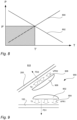
- Fig. 8 illustrates a simplified model on how blisters and pin-holes, may be formed.
- pressure P is held below a pressure threshold P' and temperature T is held below a temperature threshold T', no or at least few blisters and pinholes are formed.
- the thresholds P', T' can be determined by gauge pressure 800 and load bearing capacity of a polymer used for the strip 200.
- an air heating arrangement 900 as generally illustrated in fig. 9 can be used. Unlike present systems for strip application, the heating arrangement 900 provides individual heating of the strip 200 and the web 102. As illustrated, a first nozzle 902 may be used for providing a first flow 904 of heated air onto the web 102, and a second nozzle 906 may be used for providing a second flow 908 of heated air onto the strip 200.
- T1 for the first flow 90 and T2 for the second flow 904 it is made possible to provide sufficient heating for achieving melting of strip 200 and the web 102, respectively, such that the two can be adhered together reliably, at the same time as the risk of overheating, thereby causing blisters and delamination, can be held low.
- a first and a second volume flow rate VFR1, VFR2 may be set individually.
- the first flow 904 may be directed in a first flow direction FD1 and the second flow 904 may be directed in a second flow direction FD2.
- first flow direction FD1 the second flow 904 may be directed in a second flow direction FD2.
- Fig. 10A and 10B illustrate an example of the air heating arrangement 900 that can be attached to an existing apparatus 100.
- this air heating arrangement 900 directly upstream a PM reel holder easily accessible on one side of the apparatus 100, the strip 200 and the web 102 may be heated and adhered to each other before the web 102 is fed into the apparatus 100 and thereby not easily accessible.
- a mounting bracket 1000 can be provided such that the air heating arrangement 900 can easily be attached to the packaging machine 100.
- An advantage of having the air heating arrangement 900 placed on an outside of the packaging machine 100 and having the mounting bracket 1000, or other similar arrangement for providing easy installation, is that upgrading of existing filling machines is facilitated.
- An additional advantage of having the air heating arrangement 900 placed on the outside of the packaging machine 100 is that heating of the protective strip 200 and the web 102 can be monitored by an operator easily.
- Fig. 11 illustrates, also by way of example, the air heating arrangement 900, illustrated by way of example in fig. 10A and 10B , as well as parts of the packaging machine 100 arranged for feeding and directing the protective strip 200 such that this can be exposed to the heat via the second flow 908 from the second nozzle 906.
- Fig. 12 is a flowchart illustrating a method 1200 for producing packages 110 holding food product by way of example.
- the web 102 can be provided, and in a second step 1204, the protective strip 200 can be provided.
- the first longitudinal edge section 208 of the inside surface 214 of the web 102 can be heated by applying the first flow 904 of heated air via the first nozzle 902.
- the first longitudinal edge section 212 of the inside surface 210 of the protective strip 200 can be heated by applying the second flow 908 of heated air via the second nozzle 906.
- the outside surface 210 of the first longitudinal edge section 212 of the protective strip 200 can be attached onto the inside surface 214 of the first longitudinal edge section 212 of the web 102.
- the tube 106 can be formed from the web 102 of packaging material (PM) by directing the first longitudinal edge section 208 of the web 102 inside the second longitudinal edge section 306 of the web 102.
- PM packaging material
- a seventh step 1214 the outside surface 308 of the first longitudinal edge section 208 can be attached onto the inside surface 310 of the second longitudinal edge section 306.
- the inside surface 314 of the second longitudinal section 312 of the protective strip 200 can be attached onto the outside surface 318 of the mid-section 316 of the web 102, wherein the mid-section 316 can be placed between the first and second edge sections 208, 306, thereby providing for that the food product (FP) can be hindered from coming into contact with the cellulose-based mid-layer 304 of the packaging material (PM).
- the food product (FP) can be filled into the tube 106.
- the tube 106 can be transversally sealed in transversal sealing sections 114 in a lower end of the tube 106.
- the tube 106 can be cut in the transversal sealing sections 114 such that the packages 110 are formed.
- the different steps may also be performed in other orders and also some of the steps may be performed in parallel, e.g. the web and the protective strip may be heated in parallel.
- Fig. 13 generally illustrates an apparatus 1300 for producing packages 110 holding food product FP.
- the apparatus can comprise a web holder 1302 arranged to hold the web 102 of packaging material PM comprising at least the outer protective layer 300, the cellulose-based mid-layer 304 and the inner protective layer 302. Further, the apparatus may comprise a protective strip holder 1304 arranged to hold a protective strip (200).
- the apparatus 1300 may further comprise the air heating arrangement 900, illustrated by way of example in fig.
- first nozzle 902 can be arranged to heat the first longitudinal edge section 208 of the inside surface 214 of the web 102 by applying the first flow 904 of heated air
- second nozzle 906 can be arranged to heat the first longitudinal edge section 212 of the outside surface 210 of the protective strip 200 by applying the second flow 908 of heated air via the second nozzle 906.
- a first strip application arrangement 1306 arranged to attach the outside surface 210 of the first longitudinal edge section 212 of the protective strip 200 onto the inside surface 214 of the first longitudinal edge section 208 of the web 102.
- a tube forming arrangement 1308 may be arranged to form the tube 106 of the web 102 of packaging material PM by directing the first longitudinal edge section 208 inside the second longitudinal edge section 306 of the web 102.
- the apparatus may also comprise the longitudinal sealing arrangement 104 arranged to seal the web 102 longitudinally by attaching the outside surface 308 of the first longitudinal edge section 208 onto the inside surface 310 of the second longitudinal edge section 306.
- a second strip application arrangement 1310 arranged to attach the inside surface 314 of the second longitudinal edge section 312 of the protective strip 200 onto the outside surface 318 of the mid-section 316 of the web 102, wherein the mid-section 316 is placed between the first and second edge sections 208, 306, thereby providing for that the food product FP is restrained, or hindered, from coming into contact with the cellulose-based mid-layer 304 of the packaging material PM.
- the food product pipe 108 may be arranged to fill the food product FP into the tube 106, and also the apparatus 1300 can comprise the transversal sealing arrangement 112 arranged to seal the tube 106 transversally in transversal sealing sections 114 in the lower end of the tube 106, and to cut the tube 106 in the transversal sealing sections 114 such that the packages 110 are formed.
- Fig. 14 is a flowchart illustrating a method 1400 for preparing the web 102 of packaging material PM and a protective strip 200 before attaching these to each other.
- protective strip material data can be received.
- a first temperature T1 and/or a first volumetric flow rate VFR1 based on the protective strip material data can be determined.
- the air heating arrangement 900 can be controlled to expose the protective strip 200 to the first flow 904 of heated air via the first nozzle 902, wherein the first flow 904 has the first temperature T1 and/or the first volumetric flow rate VFR1.
- packaging material data can be received.
- a second temperature T2 and/or a second volumetric flow rate VFR2 can be determined based on the packaging material data.
- the air heating arrangement 900 can be controlled to expose the web 102 to the second flow 908 of heated air via the second nozzle 906, wherein the second flow 908 has the second temperature T2 and/or the second volumetric flow rate VFR2.
- the different steps may also be performed in other orders and also some of the steps may be performed in parallel, e.g. the web and the protective strip may be heated in parallel.
Landscapes
- Engineering & Computer Science (AREA)
- Mechanical Engineering (AREA)
- Chemical & Material Sciences (AREA)
- Physics & Mathematics (AREA)
- Thermal Sciences (AREA)
- Combustion & Propulsion (AREA)
- Composite Materials (AREA)
- Containers And Plastic Fillers For Packaging (AREA)
Applications Claiming Priority (1)
| Application Number | Priority Date | Filing Date | Title |
|---|---|---|---|
| EP22169797 | 2022-04-25 |
Publications (1)
| Publication Number | Publication Date |
|---|---|
| EP4269076A1 true EP4269076A1 (fr) | 2023-11-01 |
Family
ID=81386471
Family Applications (1)
| Application Number | Title | Priority Date | Filing Date |
|---|---|---|---|
| EP23168281.6A Pending EP4269076A1 (fr) | 2022-04-25 | 2023-04-17 | Procédé de production d'emballages, appareil et kit de pièces |
Country Status (2)
| Country | Link |
|---|---|
| EP (1) | EP4269076A1 (fr) |
| WO (1) | WO2023208628A1 (fr) |
Citations (2)
| Publication number | Priority date | Publication date | Assignee | Title |
|---|---|---|---|---|
| EP0955151A1 (fr) * | 1998-04-27 | 1999-11-10 | Tetra Laval Holdings & Finance SA | Dispositif pour le soudage d'une bande adhésive sur une feuille d'emballage pour produits alimentaires à l'état liquide |
| EP3967476A1 (fr) * | 2020-09-10 | 2022-03-16 | Tetra Laval Holdings & Finance S.A. | Procédé d'évaluation de la qualité d'un joint longitudinal et serveur |
-
2023
- 2023-04-17 EP EP23168281.6A patent/EP4269076A1/fr active Pending
- 2023-04-17 WO PCT/EP2023/059911 patent/WO2023208628A1/fr unknown
Patent Citations (2)
| Publication number | Priority date | Publication date | Assignee | Title |
|---|---|---|---|---|
| EP0955151A1 (fr) * | 1998-04-27 | 1999-11-10 | Tetra Laval Holdings & Finance SA | Dispositif pour le soudage d'une bande adhésive sur une feuille d'emballage pour produits alimentaires à l'état liquide |
| EP3967476A1 (fr) * | 2020-09-10 | 2022-03-16 | Tetra Laval Holdings & Finance S.A. | Procédé d'évaluation de la qualité d'un joint longitudinal et serveur |
Also Published As
| Publication number | Publication date |
|---|---|
| WO2023208628A1 (fr) | 2023-11-02 |
Similar Documents
| Publication | Publication Date | Title |
|---|---|---|
| EP0765818B1 (fr) | Ruban adhésif | |
| EP1666362B1 (fr) | Dispositif d'emballage/remplissage et dispositif de coupe de materiau d'emballage | |
| EP2284080B1 (fr) | Appareil d'emballage et de remplissage | |
| US5031380A (en) | Packaging machine | |
| EP1406817B1 (fr) | Procede d'epissurage d'une bande continue de paquets et bande ainsi obtenue | |
| EP1967451B1 (fr) | Dispositif de production d'un recipient d'emballage et procede de production d'un recipient d'emballage | |
| SE523861C2 (sv) | Förpackningslaminat, förfarande för tillverkning av detta, samt förpackningsbehållare tillverkad av förpackningslaminatet | |
| EP1184311B1 (fr) | Procédé de raccordement de matériaux multicouches pour emballer des produits alimentaires sous forme liquide | |
| RU2555582C2 (ru) | Устройство и способ для подачи полотна упаковочного материала | |
| US9170131B2 (en) | Apparatus and method for detecting the position of application of a sealing strip onto a web of packaging material for food products | |
| EP4269076A1 (fr) | Procédé de production d'emballages, appareil et kit de pièces | |
| US3770540A (en) | Method of splicing two laminated packaging materials together | |
| EP1010653B1 (fr) | Dispositif de raccordement de bande | |
| EP4140740A1 (fr) | Procédé de stratification et station de stratification | |
| CN216545005U (zh) | 一种缝线封口复合袋的加工制造设备 | |
| EP4368521A1 (fr) | Machine d'emballage pour produire des emballages scellés d'un produit pouvant être versé à partir d'une bande de matériau d'emballage | |
| EP4140739A1 (fr) | Procédé de stratification et station de stratification | |
| EP3398739A1 (fr) | Dispositif de découpe pour matériau d'emballage en feuille | |
| JP2012020776A (ja) | 縦型製袋充填包装機の縦シール装置 | |
| JP2004224343A (ja) | ストリップテープ及び包装容器 | |
| JP2010120695A (ja) | 包装充填装置及び包装充填方法 | |
| JP2009149364A (ja) | 包装充填装置及び包装充填方法 |
Legal Events
| Date | Code | Title | Description |
|---|---|---|---|
| PUAI | Public reference made under article 153(3) epc to a published international application that has entered the european phase |
Free format text: ORIGINAL CODE: 0009012 |
|
| STAA | Information on the status of an ep patent application or granted ep patent |
Free format text: STATUS: THE APPLICATION HAS BEEN PUBLISHED |
|
| AK | Designated contracting states |
Kind code of ref document: A1 Designated state(s): AL AT BE BG CH CY CZ DE DK EE ES FI FR GB GR HR HU IE IS IT LI LT LU LV MC ME MK MT NL NO PL PT RO RS SE SI SK SM TR |
|
| STAA | Information on the status of an ep patent application or granted ep patent |
Free format text: STATUS: REQUEST FOR EXAMINATION WAS MADE |
|
| 17P | Request for examination filed |
Effective date: 20240502 |
|
| RBV | Designated contracting states (corrected) |
Designated state(s): AL AT BE BG CH CY CZ DE DK EE ES FI FR GB GR HR HU IE IS IT LI LT LU LV MC ME MK MT NL NO PL PT RO RS SE SI SK SM TR |