EP4268994B1 - Refractory plate, method for the production of the refractory plate and use of the refractory plate - Google Patents
Refractory plate, method for the production of the refractory plate and use of the refractory plate Download PDFInfo
- Publication number
- EP4268994B1 EP4268994B1 EP22170298.8A EP22170298A EP4268994B1 EP 4268994 B1 EP4268994 B1 EP 4268994B1 EP 22170298 A EP22170298 A EP 22170298A EP 4268994 B1 EP4268994 B1 EP 4268994B1
- Authority
- EP
- European Patent Office
- Prior art keywords
- refractory
- plate
- mass
- refractory material
- refractory plate
- Prior art date
- Legal status (The legal status is an assumption and is not a legal conclusion. Google has not performed a legal analysis and makes no representation as to the accuracy of the status listed.)
- Active
Links
- 238000004519 manufacturing process Methods 0.000 title claims description 11
- 238000000034 method Methods 0.000 title claims description 7
- 239000011819 refractory material Substances 0.000 claims description 84
- PNEYBMLMFCGWSK-UHFFFAOYSA-N aluminium oxide Inorganic materials [O-2].[O-2].[O-2].[Al+3].[Al+3] PNEYBMLMFCGWSK-UHFFFAOYSA-N 0.000 claims description 38
- 229910052751 metal Inorganic materials 0.000 claims description 33
- 239000002184 metal Substances 0.000 claims description 33
- MCMNRKCIXSYSNV-UHFFFAOYSA-N Zirconium dioxide Chemical compound O=[Zr]=O MCMNRKCIXSYSNV-UHFFFAOYSA-N 0.000 claims description 32
- 229910052799 carbon Inorganic materials 0.000 claims description 31
- VYPSYNLAJGMNEJ-UHFFFAOYSA-N Silicium dioxide Chemical compound O=[Si]=O VYPSYNLAJGMNEJ-UHFFFAOYSA-N 0.000 claims description 26
- OKTJSMMVPCPJKN-UHFFFAOYSA-N Carbon Chemical compound [C] OKTJSMMVPCPJKN-UHFFFAOYSA-N 0.000 claims description 23
- 229910052593 corundum Inorganic materials 0.000 claims description 23
- 239000011230 binding agent Substances 0.000 claims description 22
- 238000004939 coking Methods 0.000 claims description 21
- 229910001845 yogo sapphire Inorganic materials 0.000 claims description 20
- CPLXHLVBOLITMK-UHFFFAOYSA-N Magnesium oxide Chemical compound [Mg]=O CPLXHLVBOLITMK-UHFFFAOYSA-N 0.000 claims description 18
- 238000005266 casting Methods 0.000 claims description 14
- 229910052681 coesite Inorganic materials 0.000 claims description 13
- 229910052906 cristobalite Inorganic materials 0.000 claims description 13
- 239000000377 silicon dioxide Substances 0.000 claims description 13
- 229910052682 stishovite Inorganic materials 0.000 claims description 13
- 229910052905 tridymite Inorganic materials 0.000 claims description 13
- JEIPFZHSYJVQDO-UHFFFAOYSA-N iron(III) oxide Inorganic materials O=[Fe]O[Fe]=O JEIPFZHSYJVQDO-UHFFFAOYSA-N 0.000 claims description 7
- ODINCKMPIJJUCX-UHFFFAOYSA-N calcium oxide Inorganic materials [Ca]=O ODINCKMPIJJUCX-UHFFFAOYSA-N 0.000 claims description 5
- 238000003825 pressing Methods 0.000 claims description 3
- 238000007599 discharging Methods 0.000 claims description 2
- 239000000463 material Substances 0.000 description 9
- 239000000395 magnesium oxide Substances 0.000 description 8
- 229910000831 Steel Inorganic materials 0.000 description 7
- 239000010959 steel Substances 0.000 description 7
- GWEVSGVZZGPLCZ-UHFFFAOYSA-N Titan oxide Chemical compound O=[Ti]=O GWEVSGVZZGPLCZ-UHFFFAOYSA-N 0.000 description 6
- 239000003963 antioxidant agent Substances 0.000 description 6
- 230000000694 effects Effects 0.000 description 6
- 239000002994 raw material Substances 0.000 description 6
- 229910001570 bauxite Inorganic materials 0.000 description 5
- 230000007797 corrosion Effects 0.000 description 5
- 238000005260 corrosion Methods 0.000 description 5
- 238000002844 melting Methods 0.000 description 5
- 230000008018 melting Effects 0.000 description 5
- 229920005989 resin Polymers 0.000 description 5
- 239000011347 resin Substances 0.000 description 5
- 230000035939 shock Effects 0.000 description 5
- 238000004088 simulation Methods 0.000 description 5
- 229910052596 spinel Inorganic materials 0.000 description 5
- 239000004568 cement Substances 0.000 description 4
- 238000006243 chemical reaction Methods 0.000 description 4
- 239000000654 additive Substances 0.000 description 3
- 150000001875 compounds Chemical class 0.000 description 3
- 238000009749 continuous casting Methods 0.000 description 3
- 239000010431 corundum Substances 0.000 description 3
- KZHJGOXRZJKJNY-UHFFFAOYSA-N dioxosilane;oxo(oxoalumanyloxy)alumane Chemical compound O=[Si]=O.O=[Si]=O.O=[Al]O[Al]=O.O=[Al]O[Al]=O.O=[Al]O[Al]=O KZHJGOXRZJKJNY-UHFFFAOYSA-N 0.000 description 3
- 239000002270 dispersing agent Substances 0.000 description 3
- 239000000203 mixture Substances 0.000 description 3
- 229910052863 mullite Inorganic materials 0.000 description 3
- 230000001590 oxidative effect Effects 0.000 description 3
- 239000011029 spinel Substances 0.000 description 3
- 229910026161 MgAl2O4 Inorganic materials 0.000 description 2
- CSDREXVUYHZDNP-UHFFFAOYSA-N alumanylidynesilicon Chemical compound [Al].[Si] CSDREXVUYHZDNP-UHFFFAOYSA-N 0.000 description 2
- SNAAJJQQZSMGQD-UHFFFAOYSA-N aluminum magnesium Chemical compound [Mg].[Al] SNAAJJQQZSMGQD-UHFFFAOYSA-N 0.000 description 2
- 230000015572 biosynthetic process Effects 0.000 description 2
- 239000000969 carrier Substances 0.000 description 2
- 229910010293 ceramic material Inorganic materials 0.000 description 2
- 238000010304 firing Methods 0.000 description 2
- 229910002804 graphite Inorganic materials 0.000 description 2
- 239000010439 graphite Substances 0.000 description 2
- 239000007788 liquid Substances 0.000 description 2
- 229910001338 liquidmetal Inorganic materials 0.000 description 2
- 229920003986 novolac Polymers 0.000 description 2
- 239000011214 refractory ceramic Substances 0.000 description 2
- 229910021487 silica fume Inorganic materials 0.000 description 2
- 238000005496 tempering Methods 0.000 description 2
- XUIMIQQOPSSXEZ-UHFFFAOYSA-N Silicon Chemical compound [Si] XUIMIQQOPSSXEZ-UHFFFAOYSA-N 0.000 description 1
- 238000010521 absorption reaction Methods 0.000 description 1
- 229910045601 alloy Inorganic materials 0.000 description 1
- 239000000956 alloy Substances 0.000 description 1
- 229910052782 aluminium Inorganic materials 0.000 description 1
- XAGFODPZIPBFFR-UHFFFAOYSA-N aluminium Chemical compound [Al] XAGFODPZIPBFFR-UHFFFAOYSA-N 0.000 description 1
- -1 aluminum magnesium silicon Chemical compound 0.000 description 1
- 229910052849 andalusite Inorganic materials 0.000 description 1
- INAHAJYZKVIDIZ-UHFFFAOYSA-N boron carbide Chemical compound B12B3B4C32B41 INAHAJYZKVIDIZ-UHFFFAOYSA-N 0.000 description 1
- 239000006229 carbon black Substances 0.000 description 1
- 239000003575 carbonaceous material Substances 0.000 description 1
- 239000011280 coal tar Substances 0.000 description 1
- 239000011294 coal tar pitch Substances 0.000 description 1
- 239000000571 coke Substances 0.000 description 1
- 238000005262 decarbonization Methods 0.000 description 1
- 238000000462 isostatic pressing Methods 0.000 description 1
- 239000011159 matrix material Substances 0.000 description 1
- 150000001247 metal acetylides Chemical class 0.000 description 1
- 150000002739 metals Chemical class 0.000 description 1
- 230000003647 oxidation Effects 0.000 description 1
- 238000007254 oxidation reaction Methods 0.000 description 1
- 239000011301 petroleum pitch Substances 0.000 description 1
- 229920001568 phenolic resin Polymers 0.000 description 1
- 239000011295 pitch Substances 0.000 description 1
- 239000000843 powder Substances 0.000 description 1
- 230000001902 propagating effect Effects 0.000 description 1
- 229910052710 silicon Inorganic materials 0.000 description 1
- 239000010703 silicon Substances 0.000 description 1
- HBMJWWWQQXIZIP-UHFFFAOYSA-N silicon carbide Chemical compound [Si+]#[C-] HBMJWWWQQXIZIP-UHFFFAOYSA-N 0.000 description 1
- 230000007704 transition Effects 0.000 description 1
- 238000003826 uniaxial pressing Methods 0.000 description 1
- XLYOFNOQVPJJNP-UHFFFAOYSA-N water Substances O XLYOFNOQVPJJNP-UHFFFAOYSA-N 0.000 description 1
Images


Classifications
-
- B—PERFORMING OPERATIONS; TRANSPORTING
- B22—CASTING; POWDER METALLURGY
- B22D—CASTING OF METALS; CASTING OF OTHER SUBSTANCES BY THE SAME PROCESSES OR DEVICES
- B22D41/00—Casting melt-holding vessels, e.g. ladles, tundishes, cups or the like
- B22D41/14—Closures
- B22D41/22—Closures sliding-gate type, i.e. having a fixed plate and a movable plate in sliding contact with each other for selective registry of their openings
- B22D41/28—Plates therefor
- B22D41/30—Manufacturing or repairing thereof
- B22D41/32—Manufacturing or repairing thereof characterised by the materials used therefor
-
- F—MECHANICAL ENGINEERING; LIGHTING; HEATING; WEAPONS; BLASTING
- F27—FURNACES; KILNS; OVENS; RETORTS
- F27D—DETAILS OR ACCESSORIES OF FURNACES, KILNS, OVENS, OR RETORTS, IN SO FAR AS THEY ARE OF KINDS OCCURRING IN MORE THAN ONE KIND OF FURNACE
- F27D3/00—Charging; Discharging; Manipulation of charge
- F27D3/15—Tapping equipment; Equipment for removing or retaining slag
- F27D3/1509—Tapping equipment
- F27D3/1518—Tapholes
Definitions
- the invention relates to a refractory plate for use in a slide gate valve for controlling a flow of molten metal, a method for the production of the refractory plate and a use of the refractory plate.
- Refractory plates in a slide gate valve serve to control a flow rate of molten (i.e., liquid) metal, especially steel, from a melting vessel for receiving liquid or molten metal, respectively.
- a vessel may in particular be a ladle or tundish in a continuous casting plant for casting steel.
- Such vessels In order to pour a metal melt in such a vessel into an aggregate downstream of the vessel in terms of production, such vessels have an opening which is arranged in particular at the bottom of such vessels.
- Refractory plates in a slide gate valve are used to control the flow of molten metal through such an opening.
- Such plates have a channel or passage opening through which liquid metal can flow.
- a slide gate valve is located in the area of the opening of the melting vessel.
- Such a slide gate valve comprises several refractory plates to control the flow of molten steel from the opening.
- a slide gate valve regularly comprises one or two fixed refractory plates, each of which has a channel which is aligned with the opening of the melting vessel.
- Another refractory plate, the so-called “slide gate plate” lies flat against the fixed plates and is arranged so as to be slidable relative to these fixed plates.
- the slide gate plate can be slid into a first position in which the channel of the slide gate plate is aligned with the channel openings of the fixed plates so that the molten metal can flow out of the melting vessel through the opening of the melting vessel and the aligned channel openings of the plates. Furthermore, the slide gate plate can be moved to a second position in which the channel openings of the fixed plates are closed by the slide gate plate. In addition, the slide gate plate can be used for throttling the steel flow by moving it to positions between first and second position. A hydraulic or electric drive can be provided to move the slide gate plate.
- Plates in a slide gate valve consist of refractory ceramic materials.
- the refractory ceramic material of the plate In order to withstand these extreme loads, the refractory ceramic material of the plate must not only have a high refractoriness but also a high thermal shock resistance and a high corrosion resistance.
- RU 2677400 C1 discloses a slide gate plate, having an insert, installed in a through-hole of a base, wherein the insert is made of refractory material on the basis of tabular alumina, containing not less than 80% by mass of Al 2 O 3 , not less than 5% by mass of ZrO 2 and not more than 7% by mass of C, and wherein the base material is made of refractory material based on tabular alumina containing at least 90% by mass of Al 2 O 3 .
- KR20000043950 A discloses a plate of a sliding gate valve, having an interpolation part, mortared into a body part, the interpolation part made of a carbon comprising material and the body part made of zirconia mullite and alumina.
- the plate shall have good refractory properties, such as high refractoriness, good thermal shock resistance and high corrosion resistance.
- the invention is directed to providing a vessel for holding molten metal comprising such a refractory plate.
- a refractory plate comprises the features of claim 1.
- a plate formed as above can solve the problems underlying the invention.
- a refractory plate can exhibit the aforementioned good refractory properties and at the same time form a high resistance to ratholing.
- the invention is based on the finding that it is not easily possible to provide a refractory plate that has both good refractory properties and a high resistance to ratholing when it is made of only one refractory material. Rather, it is necessary to form the refractory plate from different refractory materials, each having different properties and synergistically complementing each other in terms of their effect.
- the invention is further based on the finding that only refractory materials that are carbon bonded or have a coking binder, have the desired high refractory properties of good refractoriness (high temperature resistance), good thermal shock resistance and high corrosion resistance.
- a “coking binder” shall mean a binder capable of undergoing a coking reaction when exposed to high temperatures.
- the coking reaction leads to a carbon bond.
- the high temperatures necessary for such coking reaction are usually reached under operating conditions of such slide gate plates.
- the necessary temperatures for such coking reactions start at about 600°C.
- Examples of coking binders include coal tar pitch, phenol-formaldehyde resins (Novolaks, Resols) and petroleum pitch.
- the invention is further based on the finding that a refractory plate in a slide gate valve is exposed to an oxidizing atmosphere during its use substantially only in its outer region, i.e., the region spaced from the channel, while the region immediately surrounding the channel is hardly exposed to such an oxidizing atmosphere.
- a refractory plate comprising two different refractory materials, namely a first refractory material which is carbon-bonded or has a coking binder, which encompasses the channel, and a second refractory material which is spaced from the channel and encompasses the first refractory material and which is not bonded by a carbon bond and not having a coking binder.
- such a refractory slide plate also provides a high resistance to the effect of ratholing.
- cracks which form in the first refractory material in the region of the channel or passage opening, respectively run essentially only through the first refractory material and fizzle out or die at the outer edge of the first refractory material or the interface or transition region from the first refractory material to the second refractory material.
- cracks also form in the second refractory material, they are in no relationship to the cracks of the first refractory material. In turn, cracks are not propagating from first to second refractory material through the interface between the two materials. In this way, the effect of ratholing can be largely or even completely suppressed.
- the first refractory material can be made of any refractory material known from the art to be used for a refractory plate in a slide gate valve, and which is bonded by a carbon bond or has a coking binder.
- the first refractory material may be based on at least one of the following refractory materials: Alumina (i.e., refractory materials based on Al 2 O 3 ), magnesia (i.e., refractory materials based on MgO), spinel (i.e., refractory materials based on MgAl 2 O 4 ) and bauxite (i.e., a refractory material based on Al 2 O 3 with minor amounts of Fe 2 O 3 , SiO 2 and TiO 2 ).
- Alumina i.e., refractory materials based on Al 2 O 3
- magnesia i.e., refractory materials based on MgO
- spinel i.e.,
- refractory materials based on zirconia i.e., refractory materials based on ZrO 2
- zirconia mullite i.e., refractory materials based on ZrO 2 + 3Al 2 O 3 ⁇ 2SiO 2
- zirconia corundum zirconia spinel or micro silica.
- the refractory materials may comprise scrap or secondary (i.e., used and recycled) raw materials.
- the materials may comprise antioxidants known from the prior art, in particular metals or carbides. As known from the art, antioxidants are used to prevent decarbonization and to foster carbide formation in order to increase the strength of the refractory material.
- the antioxidants are present as a powder.
- the antioxidants are selected from the following group: aluminum (Al), silicon (Si), boron carbide (B 4 C), silicon carbide (SiC), and aluminum silicon (AlSi), aluminum magnesium (AIMg), and aluminum magnesium silicon (AlMgSi) alloys.
- the first refractory may further comprise carbon-containing materials, such as graphite, carbon black and petrol coke in order to decrease porosity and/or to flexibilize the matrix. In the case of a carbon bond, the aforementioned materials are bonded to each other via a carbon bond, as known from the prior art.
- the materials of the first refractory material are bonded via a coking binder.
- the coking binder may be one of the coking binders known from the prior art, which are coked by means of tempering and/or firing under reducing conditions and thereby form a binding carbon skeleton.
- the coking binder may be at least one of the following: coal tar pitches and resins. Resins may be at least one of the following: Novolaks and Resols.
- the coking binder may be at least one resins, particularly preferably at least one of the aforementioned resins.
- the first refractory material is comprised of 2 to 20% by mass of carbon and of 80 to 98% by mass of at least one oxide selected from the group consisting of: Al 2 O 3 , SiO 2 , ZrO 2 and MgO.
- the first refractory material is comprised of 3 to 15% by mass carbon, of 85 to 97% by mass of at least one oxide selected from the group consisting of: Al 2 O 3 , SiO 2 , ZrO 2 and MgO.
- the first refractory material is comprised of 3 to 11% by mass of carbon, of 89 to 97% by mass of at least one oxide selected from the group consisting of: Al 2 O 3 , SiO 2 , ZrO 2 and MgO.
- the first refractory material is comprised of 6 to 9% by mass carbon, of 91 to 94% by mass of at least one oxide selected from the group consisting of: Al 2 O 3 , SiO 2 , ZrO 2 and MgO.
- the above mass fractions of the components of the first refractory material are based on the total mass of the first refractory material.
- the second refractory material is not bonded by a carbon bond or a coking binder. Rather, the second refractory material has a carbon content of less than 2% by mass, particularly preferable of less than 1% by mass.
- the second refractory material can be made of any refractory material known from the art to be used for a refractory plate in a slide gate valve, and which is not bonded by a carbon bond and does not have a coking binder.
- the second refractory material can be made of any refractory material known from the art, and which is not bonded by a carbon bond and has no coking binder.
- the second refractory material may be based on at least one of the following refractory materials: Alumina (i.e., refractory materials based on Al 2 O 3 ), magnesia (i.e., refractory materials based on MgO), spinel (i.e., refractory materials based on MgAl 2 O 4 ), bauxite (i.e., a refractory material based on Al 2 O 3 with minor amounts of Fe 2 O 3 , SiO 2 and TiO 2 ), mullite and fireclay.
- Alumina i.e., refractory materials based on Al 2 O 3
- magnesia i.e., refractory materials based on MgO
- spinel i.e., refractory materials based on MgA
- the refractory materials may comprise scrap or secondary (i.e., used and recycled) raw materials. These materials may be supplemented, for example, by different additives, for example, microsilica, andalusite, alumina cement (i.e., cements based on Al 2 O 3 and CaO) and dispersing agents.
- microsilica, andalusite i.e., alumina cement (i.e., cements based on Al 2 O 3 and CaO) and dispersing agents.
- the second refractory material is based on alumina, i.e., a refractory material based on Al 2 O 3 .
- "Based on” means that, preferably, Al 2 O 3 is the main oxide, present in a higher mass fraction than any other oxide.
- the second refractory material is comprised of 35 to 99% by mass Al 2 O 3 , of below 2% by mass carbon and of 1 to 65% by mass at least one of the following: SiO 2 , CaO and Fe 2 O 3 .
- the second refractory material is comprised of 50 to 99% by mass Al 2 O 3 , of below 2% by mass carbon and of 1 to 50% by mass at least one of the following: SiO 2 , CaO and Fe 2 O 3 .
- the second refractory material is comprised of 65 to 99% by mass Al 2 O 3 , of below 2% by mass carbon and of 1 to 35% by mass at least one of the following: SiO 2 , CaO and Fe 2 O 3 .
- the above proportions of carbon and oxides in the first and second refractory materials are determined by a combination of the standards ISO 12677 and ISO 21068-2.
- the proportion of oxides was determined to 100% by mass according to ISO 12677.
- the proportion of carbon was determined according to ISO 21068-2.
- the determined 100% by mass of oxides and the determined % by mass of carbon were added.
- the resulting total mass (100% by mass oxides plus % by mass carbon) was then normalized to 100% by mass.
- the first portion of the refractory plate according to the invention is made of the first refractory material.
- the first portion is made by pressing.
- the first portion is made by uniaxial pressing or isostatic pressing.
- the first portion is one-piece.
- the first portion is particularly easy to manufacture and to handle for the manufacture of the refractory plate according to the invention.
- the second portion of the refractory plate according to the invention is made of the second refractory material.
- the second portion is monolithic.
- the second portion is made by casting.
- the second portion is monolithic or is produced by casting
- the second portion has the particular advantage that it is particularly easy to produce and has a particularly homogeneous structure.
- this also has the advantage of a very uniform force absorption, whereby stresses can be distributed and the crack propagation from first to second portion can be effectively prevented.
- the first portion and said second portion abut at an interface. To this extent, the first portion lies directly against the second portion. This has the particular advantage that forces emanating from the first portion can be absorbed by the second portion and dissipated to the outside. This can further prevent the formation of cracks.
- ratholing can be prevented particularly effectively if the second portion completely surrounds or encompasses, respectively, the first portion.
- the second portion completely surrounds the first portion in the plane of the refractory plate, i.e., in a plane normal to the longitudinal axis of the channel. It was found that ratholing can be reduced particularly effectively if the second portion completely surrounds the first portion with a thickness of at least 5 mm. According to a preferred embodiment, it is therefore provided that the second portion completely surrounds the first portion in a thickness of at least 5 mm, more preferably a thickness of at least 10 mm.
- the second portion occupies a minimum volume, in particular a volume of at least 10%, relative to the total volume of the first and second portion.
- the second portion has a volume in the range of 10 to 90% by volume and the first portion has a volume in the range of 90 to 10% by volume, even more preferably that the second portion has a volume in the range of 30 to 70% by volume and the first portion has a volume in the range of 70 to 30% by volume, each relative to the total volume of the first and second portion.
- the first portion and the second portion are arranged in a frame.
- Corresponding frames for holding a refractory material of a slide plate are known in the art.
- the frame of the refractory plate according to the invention can be designed according to frames known from the prior art.
- the frame is made of metal.
- the frame may preferably comprise a bottom part and a rim part, the rim part projecting, preferably perpendicularly, from the bottom part at the edge thereof.
- the frame only comprises a rim part without a bottom part; in this case, the rim part forms a bandage. To this extent, the rim part forms the radial outer circumference or periphery, respectively, of the frame.
- the first portion is arranged with a distance from a radial outer circumference of the frame. Accordingly, if the frame comprises a rim part, as set forth above, the first portion is arranged with a distance from a rim of the frame. Preferably, this distance is at least 5 mm and particularly preferably at least 10 mm.
- the second portion bridges the distance between the first portion and the radial outer circumference or rim of the frame.
- ratholing can be counteracted particularly effectively when said second portion bridges said distance or gap between the first portion and the radial outer circumference of the frame.
- the channel runs at least partially through the first portion.
- the channel is fully passing through the first portion.
- the channel is fully enclosed by the first portion, such that molten metal flowing through the channel does not contact the second portion and preferably only contacts the first portion and thus the first refractory material.
- the first portion is made from the first refractory material, preferably by pressing.
- a batch is provided from which the second portion can be made. Accordingly, the batch can be made according to the second refractory material described before. According to the invention, the batch is provided as a castable, i.e., a refractory castable compound. This has the particular advantage that the slide gate plate according to the invention is particularly easy to manufacture.
- the batch can be cast to form the second portion, so that, after casting, it forms the second portion, whereby the first portion can be embedded in the casting compound or the second portion formed therefrom.
- first the first portion is arranged and then the batch is cast around the first portion in such a way that the batch forms the second portion after casting and the first portion is arranged in the second portion.
- first the first portion is arranged in the frame and then the batch is cast around the first portion in the frame so that the batch forms the second portion and the first portion is embedded in the second portion.
- the first portion and the frame may be fixed relative to each other by means of a casting mold.
- a further object of the invention is the use a refractory plate, as disclosed herein, in a slide gate valve for controlling a flow of molten metal.
- a further object of the invention is a slide gate valve for controlling a flow of molten metal, comprising the refractory plate as disclosed herein.
- the slide gate valve for controlling a flow of molten metal may comprise one or several of the refractory plates as disclosed herein.
- a further object of the invention is to provide a vessel for containing molten metal comprising the following features:
- the vessel is a ladle or a tundish of a continuous casting machine for the continuous casting of molten metal, especially of molten steel.
- the vessel is a ladle of an ingot casting arrangement for the casting of molten metal, especially of molten steel.
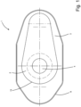
- Figure 1 shows a top view of an embodiment of a refractory plate according to the invention.
- the refractory plate in Figure 1 is denoted by the reference sign 1.
- the plate 1 comprises a first portion 2 made of a first refractory material and a second portion 3 made of a second refractory material.
- a channel 4 extends through the first portion 2 and is completely enclosed by the first portion 2.
- the plate 1 further comprises a metal frame 6 in which the first portion 2 and second portion 3 are fully incorporated.
- the first portion 2 and second portion 3 are in direct contact with each other and, hence, abut at an interface 15.
- the metal frame 6 comprises a bottom portion 7 and a radial outer rim portion 8 extending perpendicularly away from the edge 9 of the bottom portion 7.
- the bottom portion 7 has an opening 12.
- the frame 6 thus has a substantially bowl-shaped configuration with an opening 12 in its bottom 7.
- the first portion 2 has a central section 10 which is mainly arranged above the opening 12 of the bottom portion 7.
- the channel 4 extends along a longitudinal axis 11, and leads completely through this central section 10 and enters into opening 12, so that the channel 4 forms a free through-opening through the plate 1.
- the central section 10 has a circumferential collar 13, said collar 13 having an extended section 14 extending towards one side of the rim portion 8.
- the rim portion 8 of the frame 6 forms a radial outer circumference of the frame 6, to which the first portion 2 is always arranged with a distance.
- the second portion 3 occupies the entire space between the first portion 2 and the metal frame 6.
- the first portion 2 is thereby completely enclosed by the second portion 3, at any area with a minimum thickness of at least 10 mm.
- the first portion 2 occupies a volume of about 35% by volume and the second portion 3 a volume of about 65% by volume.
- the first portion 2 and second portion 3 are in direct contact with each other and, hence, abut at an interface 15.
- the first portion 2 is one-piece and is provided as a carbon-bonded first refractory material.
- Example 1 Tabular alumina > 0.045 - 2.0 mm 48 53 Tabular alumina > 0.0 - 0.045 mm 24 25 Zirconia corundum ⁇ 2.0 mm 14 Secondary raw material (alumina based) 9 Antioxidants 6 6 Carbon carriers 4 3 Binder 4 4
- Example 1 As shown in Table 1, a mixture of alumina refractories with zirconia corundum refractories was used in Example 1.
- Example 2 a mixture of alumina refractories with secondary raw materials (based on alumina) was used.
- the carbon carriers mentioned in Table 1 comprised graphite.
- the antioxidants mentioned in Table 1 comprised Si and/or Al. Both batches according to Examples 1 and 2 were further mixed with a resin binder.
- the second portion 3 is monolithic and made from a castable second refractory material. Two exemplary batches (Example 3 and 4) of such second refractory material were fabricated to produce the second portion 3, wherein raw materials in the form of alumina and bauxite were used (see Table 3).
- the batch further comprised additives and/or a dispersing agent and a binder (alumina refractory cement), as shown in Table 3 (all proportions in percent by mass, based on the respective total mass of the respective part): Table 3
- Example 3 Tabular alumina > 0.0 - 3.0 mm 58
- Additives/Dispersing Agent 1.5 Binder (alumina refractory cement) 6.5 5
- the castable was produced by adding water to the batches of Example 3 and 4.
- the oxide composition of the two embodiments of the castables, according to Examples 3 and 4, is shown in Table 4 below (all proportions in percent by mass, based on the respective total mass of the respective part): Table 4
- Example 3 Example 4 Al 2 O 3 97.8 85.0 SiO 2 0.1 10.0 TiO 2 2.5 Fe 2 O 3 0.1 1.1 Remainder 2.0 1.4
- the plate 1 was manufactured by first providing a metal frame 6 and then fixing the metal frame 6 and the first portion 2 relative to each other by means of a mold such that the first portion 2 was positioned within metal frame 6.
- the first portion 2 was one of the two parts according to the above Examples 1 or 2.
- the prior art plate 100 was made of a single refractory material 101. It is easy to see how cracks run throughout the refractory material 101 from the area of the channel 102 to the outer edge of the plate 100. In the practical application of such a plate 100, these cracks will result in increased ratholing.
Landscapes
- Engineering & Computer Science (AREA)
- Mechanical Engineering (AREA)
- Manufacturing & Machinery (AREA)
- General Engineering & Computer Science (AREA)
- Casting Support Devices, Ladles, And Melt Control Thereby (AREA)
Description
- The invention relates to a refractory plate for use in a slide gate valve for controlling a flow of molten metal, a method for the production of the refractory plate and a use of the refractory plate.
- Refractory plates in a slide gate valve serve to control a flow rate of molten (i.e., liquid) metal, especially steel, from a melting vessel for receiving liquid or molten metal, respectively. Such a vessel may in particular be a ladle or tundish in a continuous casting plant for casting steel. In order to pour a metal melt in such a vessel into an aggregate downstream of the vessel in terms of production, such vessels have an opening which is arranged in particular at the bottom of such vessels.
- Refractory plates in a slide gate valve are used to control the flow of molten metal through such an opening. Such plates have a channel or passage opening through which liquid metal can flow.
- A slide gate valve is located in the area of the opening of the melting vessel. Such a slide gate valve comprises several refractory plates to control the flow of molten steel from the opening. To this extent, such a slide gate valve regularly comprises one or two fixed refractory plates, each of which has a channel which is aligned with the opening of the melting vessel. Another refractory plate, the so-called "slide gate plate", lies flat against the fixed plates and is arranged so as to be slidable relative to these fixed plates. The slide gate plate can be slid into a first position in which the channel of the slide gate plate is aligned with the channel openings of the fixed plates so that the molten metal can flow out of the melting vessel through the opening of the melting vessel and the aligned channel openings of the plates. Furthermore, the slide gate plate can be moved to a second position in which the channel openings of the fixed plates are closed by the slide gate plate. In addition, the slide gate plate can be used for throttling the steel flow by moving it to positions between first and second position. A hydraulic or electric drive can be provided to move the slide gate plate.
- Plates in a slide gate valve consist of refractory ceramic materials.
- During the passage of liquid metal through the channel of the plate, it is exposed to extreme temperature changes, extreme temperatures and extreme mechanical or corrosive attack. The extreme temperature changes occur not only during the opening and closing of the gate valve but also during the passage of the molten metal through the channel due to temperature gradients within the plate.
- In order to withstand these extreme loads, the refractory ceramic material of the plate must not only have a high refractoriness but also a high thermal shock resistance and a high corrosion resistance.
- Despite the high thermal shock resistance and high corrosion resistance that prior art slide gate plates exhibit, the extreme temperature changes to which slide gate plates are subjected during their use lead to cracks in the plate. These cracks extend, starting from the channel, through the entire plate to its outer edge, where the plate is usually enclosed by a metal frame. Air can be drawn into the channel via these cracks due to the negative pressure that originates from adjusting the channel opening with the slide plate position to throttle the flow of steel during casting. This increases crack widening and crack propagation, which in turn increases the air intake. This effect is also known as "ratholing", which in turn leads to a significantly reduced performance of the slide plate and increased operating risks (such as break-outs, production losses, etc.).
- There has been no lack of attempts to counteract the effect of ratholing, for example by selecting special refractory materials for the refractory plate in a slide gate. In this respect, for example, carbon-bonded refractory materials are known to have excellent refractory properties, including in particular good refractoriness (high-temperature resistance), good thermal shock resistance and high corrosion resistance. However, carbon-bonded refractory materials are susceptible to oxidizing atmospheres, which the plate in a slide gate is sometimes exposed to during its service.
-
RU 2677400 C1 KR20000043950 A - It is an object of the invention to provide a refractory plate for a slide gate valve which has good refractory properties and which at the same time offers a high resistance to the effect of ratholing. In particular, the plate shall have good refractory properties, such as high refractoriness, good thermal shock resistance and high corrosion resistance.
- Furthermore, it is an object of the invention to provide a method for manufacturing such a plate.
- Furthermore, the invention is directed to providing a vessel for holding molten metal comprising such a refractory plate.
- In order to solve the problem, according to the invention, there is provided a refractory plate comprises the features of claim 1.
- Surprisingly, it has been found in accordance with the invention that a plate formed as above can solve the problems underlying the invention. In particular, such a refractory plate can exhibit the aforementioned good refractory properties and at the same time form a high resistance to ratholing.
- The invention is based on the finding that it is not easily possible to provide a refractory plate that has both good refractory properties and a high resistance to ratholing when it is made of only one refractory material. Rather, it is necessary to form the refractory plate from different refractory materials, each having different properties and synergistically complementing each other in terms of their effect.
- The invention is further based on the finding that only refractory materials that are carbon bonded or have a coking binder, have the desired high refractory properties of good refractoriness (high temperature resistance), good thermal shock resistance and high corrosion resistance.
- A "coking binder" shall mean a binder capable of undergoing a coking reaction when exposed to high temperatures. The coking reaction leads to a carbon bond. Further, as well known from the art, the high temperatures necessary for such coking reaction are usually reached under operating conditions of such slide gate plates. The necessary temperatures for such coking reactions start at about 600°C. Examples of coking binders include coal tar pitch, phenol-formaldehyde resins (Novolaks, Resols) and petroleum pitch.
- The invention is further based on the finding that a refractory plate in a slide gate valve is exposed to an oxidizing atmosphere during its use substantially only in its outer region, i.e., the region spaced from the channel, while the region immediately surrounding the channel is hardly exposed to such an oxidizing atmosphere.
- Against the background of these findings, the inventive idea arose to provide a refractory plate comprising two different refractory materials, namely a first refractory material which is carbon-bonded or has a coking binder, which encompasses the channel, and a second refractory material which is spaced from the channel and encompasses the first refractory material and which is not bonded by a carbon bond and not having a coking binder.
- In accordance with the invention, it has surprisingly been found that such a refractory slide plate also provides a high resistance to the effect of ratholing. This is because, surprisingly, it has been found that cracks which form in the first refractory material in the region of the channel or passage opening, respectively, run essentially only through the first refractory material and fizzle out or die at the outer edge of the first refractory material or the interface or transition region from the first refractory material to the second refractory material. Although cracks also form in the second refractory material, they are in no relationship to the cracks of the first refractory material. In turn, cracks are not propagating from first to second refractory material through the interface between the two materials. In this way, the effect of ratholing can be largely or even completely suppressed.
- In principle, the first refractory material can be made of any refractory material known from the art to be used for a refractory plate in a slide gate valve, and which is bonded by a carbon bond or has a coking binder. Preferably, the first refractory material may be based on at least one of the following refractory materials: Alumina (i.e., refractory materials based on Al2O3), magnesia (i.e., refractory materials based on MgO), spinel (i.e., refractory materials based on MgAl2O4) and bauxite (i.e., a refractory material based on Al2O3 with minor amounts of Fe2O3, SiO2 and TiO2). These materials may be supplemented, for example, by refractory materials based on zirconia (i.e., refractory materials based on ZrO2) or zirconia mullite (i.e., refractory materials based on ZrO2 + 3Al2O3 · 2SiO2), zirconia corundum, zirconia spinel or micro silica. The refractory materials may comprise scrap or secondary (i.e., used and recycled) raw materials. Furthermore, the materials may comprise antioxidants known from the prior art, in particular metals or carbides. As known from the art, antioxidants are used to prevent decarbonization and to foster carbide formation in order to increase the strength of the refractory material. Preferably, the antioxidants are present as a powder. Preferably, the antioxidants are selected from the following group: aluminum (Al), silicon (Si), boron carbide (B4C), silicon carbide (SiC), and aluminum silicon (AlSi), aluminum magnesium (AIMg), and aluminum magnesium silicon (AlMgSi) alloys. The first refractory may further comprise carbon-containing materials, such as graphite, carbon black and petrol coke in order to decrease porosity and/or to flexibilize the matrix. In the case of a carbon bond, the aforementioned materials are bonded to each other via a carbon bond, as known from the prior art. Insofar as the first refractory material comprises a coking binder, the materials of the first refractory material, in particular thus for example the aforementioned materials, are bonded via a coking binder. The coking binder may be one of the coking binders known from the prior art, which are coked by means of tempering and/or firing under reducing conditions and thereby form a binding carbon skeleton. In particular, the coking binder may be at least one of the following: coal tar pitches and resins. Resins may be at least one of the following: Novolaks and Resols. Preferably, the coking binder may be at least one resins, particularly preferably at least one of the aforementioned resins.
- According to a preferred embodiment, the first refractory material is comprised of 2 to 20% by mass of carbon and of 80 to 98% by mass of at least one oxide selected from the group consisting of: Al2O3, SiO2, ZrO2 and MgO.
- More preferably, the first refractory material is comprised of 3 to 15% by mass carbon, of 85 to 97% by mass of at least one oxide selected from the group consisting of: Al2O3, SiO2, ZrO2 and MgO.
- Even more preferably, the first refractory material is comprised of 3 to 11% by mass of carbon, of 89 to 97% by mass of at least one oxide selected from the group consisting of: Al2O3, SiO2, ZrO2 and MgO.
- Even more preferable, the first refractory material is comprised of 6 to 9% by mass carbon, of 91 to 94% by mass of at least one oxide selected from the group consisting of: Al2O3, SiO2, ZrO2 and MgO.
- The above mass fractions of the components of the first refractory material are based on the total mass of the first refractory material.
- The second refractory material is not bonded by a carbon bond or a coking binder. Rather, the second refractory material has a carbon content of less than 2% by mass, particularly preferable of less than 1% by mass.
- Generally, the second refractory material can be made of any refractory material known from the art to be used for a refractory plate in a slide gate valve, and which is not bonded by a carbon bond and does not have a coking binder.
- In principle, the second refractory material can be made of any refractory material known from the art, and which is not bonded by a carbon bond and has no coking binder. Preferably, the second refractory material may be based on at least one of the following refractory materials: Alumina (i.e., refractory materials based on Al2O3), magnesia (i.e., refractory materials based on MgO), spinel (i.e., refractory materials based on MgAl2O4), bauxite (i.e., a refractory material based on Al2O3 with minor amounts of Fe2O3, SiO2 and TiO2), mullite and fireclay. The refractory materials may comprise scrap or secondary (i.e., used and recycled) raw materials. These materials may be supplemented, for example, by different additives, for example, microsilica, andalusite, alumina cement (i.e., cements based on Al2O3 and CaO) and dispersing agents.
- Preferably, the second refractory material is based on alumina, i.e., a refractory material based on Al2O3. "Based on" means that, preferably, Al2O3 is the main oxide, present in a higher mass fraction than any other oxide.
- The second refractory material is comprised of 35 to 99% by mass Al2O3, of below 2% by mass carbon and of 1 to 65% by mass at least one of the following: SiO2, CaO and Fe2O3.
- More preferably, the second refractory material is comprised of 50 to 99% by mass Al2O3, of below 2% by mass carbon and of 1 to 50% by mass at least one of the following: SiO2, CaO and Fe2O3.
- Even more preferably, the second refractory material is comprised of 65 to 99% by mass Al2O3, of below 2% by mass carbon and of 1 to 35% by mass at least one of the following: SiO2, CaO and Fe2O3.
- The above proportions of carbon and oxides in the first and second refractory materials are determined by a combination of the standards ISO 12677 and ISO 21068-2. For this purpose, the proportion of oxides was determined to 100% by mass according to ISO 12677. Secondly, the proportion of carbon was determined according to ISO 21068-2. Then, the determined 100% by mass of oxides and the determined % by mass of carbon were added. The resulting total mass (100% by mass oxides plus % by mass carbon) was then normalized to 100% by mass.
- The first portion of the refractory plate according to the invention is made of the first refractory material.
- Preferably, the first portion is made by pressing. Particularly preferably, the first portion is made by uniaxial pressing or isostatic pressing.
- Preferably, the first portion is one-piece.
- By providing the first portion as one-piece, this is particularly easy to manufacture and to handle for the manufacture of the refractory plate according to the invention.
- The second portion of the refractory plate according to the invention is made of the second refractory material.
- Preferably, the second portion is monolithic.
- Particularly preferably, the second portion is made by casting.
- In that the second portion is monolithic or is produced by casting, the second portion has the particular advantage that it is particularly easy to produce and has a particularly homogeneous structure. In particular, this also has the advantage of a very uniform force absorption, whereby stresses can be distributed and the crack propagation from first to second portion can be effectively prevented.
- The first portion and said second portion abut at an interface. To this extent, the first portion lies directly against the second portion. This has the particular advantage that forces emanating from the first portion can be absorbed by the second portion and dissipated to the outside. This can further prevent the formation of cracks.
- According to the invention, it was found that ratholing can be prevented particularly effectively if the second portion completely surrounds or encompasses, respectively, the first portion. Preferably, the second portion completely surrounds the first portion in the plane of the refractory plate, i.e., in a plane normal to the longitudinal axis of the channel. It was found that ratholing can be reduced particularly effectively if the second portion completely surrounds the first portion with a thickness of at least 5 mm. According to a preferred embodiment, it is therefore provided that the second portion completely surrounds the first portion in a thickness of at least 5 mm, more preferably a thickness of at least 10 mm. Furthermore, it has been found according to the invention that ratholing can be counteracted particularly effectively if the second portion occupies a minimum volume, in particular a volume of at least 10%, relative to the total volume of the first and second portion. According to a preferred embodiment, it is therefore provided that the second portion has a volume in the range of 10 to 90% by volume and the first portion has a volume in the range of 90 to 10% by volume, even more preferably that the second portion has a volume in the range of 30 to 70% by volume and the first portion has a volume in the range of 70 to 30% by volume, each relative to the total volume of the first and second portion.
- Preferably, the first portion and the second portion are arranged in a frame.
- Corresponding frames for holding a refractory material of a slide plate are known in the art. The frame of the refractory plate according to the invention can be designed according to frames known from the prior art. Preferably, the frame is made of metal.
- As known from the prior art, the frame may preferably comprise a bottom part and a rim part, the rim part projecting, preferably perpendicularly, from the bottom part at the edge thereof. Alternatively, the frame only comprises a rim part without a bottom part; in this case, the rim part forms a bandage. To this extent, the rim part forms the radial outer circumference or periphery, respectively, of the frame.
- Preferably, the first portion is arranged with a distance from a radial outer circumference of the frame. Accordingly, if the frame comprises a rim part, as set forth above, the first portion is arranged with a distance from a rim of the frame. Preferably, this distance is at least 5 mm and particularly preferably at least 10 mm.
- According to the invention, it has been found that oxidation of the first portion as well as the occurrence of ratholing can be counteracted particularly effectively if the first portion is arranged with a distance from the radial outer circumference of the frame.
- According to a preferred embodiment, the second portion bridges the distance between the first portion and the radial outer circumference or rim of the frame.
- According to the invention, it was found that ratholing can be counteracted particularly effectively when said second portion bridges said distance or gap between the first portion and the radial outer circumference of the frame.
- The channel runs at least partially through the first portion. According to a particularly preferred embodiment, the channel is fully passing through the first portion. In other words, the channel is fully enclosed by the first portion, such that molten metal flowing through the channel does not contact the second portion and preferably only contacts the first portion and thus the first refractory material.
- It is also an object of the invention to provide a method for the production of the refractory plate according to the invention, the method comprising the following steps:
- providing the first portion;
- providing a batch from which the second portion is castable;
- casting the batch to form the second portion;
- embedding the first portion in the second portion.
- As previously disclosed, the first portion is made from the first refractory material, preferably by pressing.
- Further, a batch is provided from which the second portion can be made. Accordingly, the batch can be made according to the second refractory material described before. According to the invention, the batch is provided as a castable, i.e., a refractory castable compound. This has the particular advantage that the slide gate plate according to the invention is particularly easy to manufacture.
- In this respect, for the production of the slide gate plate according to the invention, the batch can be cast to form the second portion, so that, after casting, it forms the second portion, whereby the first portion can be embedded in the casting compound or the second portion formed therefrom.
- According to a particularly preferred embodiment, it is provided that first the first portion is arranged and then the batch is cast around the first portion in such a way that the batch forms the second portion after casting and the first portion is arranged in the second portion.
- According to a further embodiment of this method, it is particularly preferred to further provide a frame formed as above and to cast the batch into the frame.
- According to a particularly preferred further embodiment of this inventive idea, it is provided that first the first portion is arranged in the frame and then the batch is cast around the first portion in the frame so that the batch forms the second portion and the first portion is embedded in the second portion. For casting, the first portion and the frame may be fixed relative to each other by means of a casting mold.
- A further object of the invention is the use a refractory plate, as disclosed herein, in a slide gate valve for controlling a flow of molten metal.
- A further object of the invention is a slide gate valve for controlling a flow of molten metal, comprising the refractory plate as disclosed herein.
- The slide gate valve for controlling a flow of molten metal may comprise one or several of the refractory plates as disclosed herein.
- A further object of the invention is to provide a vessel for containing molten metal comprising the following features:
- an opening for discharging a flow of molten metal from said vessel; and
- a slide gate valve as disclosed herein; wherein
- the flow of molten metal through the opening is controllable by the slide gate valve.
- Preferably, the vessel is a ladle or a tundish of a continuous casting machine for the continuous casting of molten metal, especially of molten steel. Alternatively, the vessel is a ladle of an ingot casting arrangement for the casting of molten metal, especially of molten steel.
- Further features of the invention are apparent from the claims, the figures and the accompanying description of the figures.
- All features of the invention may, individually or in combination, be combined with each other in any manner.
- Examples of embodiments of the invention are also explained in more detail below with reference to the figures. In the Figures,
- Figure 1
- shows a top view of an embodiment of a refractory plate according to the invention;
- Figure 2
- shows a sectional view of a longitudinal cross-section through the plate according to
Figure 1 ; - Figure 3
- shows a perspective view of a longitudinal cross-section of the plate according to
Figure 1 ; - Figure 4
- shows the result of a simulation test on the occurrence of cracks due to stresses in a plate according to
Figure 1 ; and - Figure 5
- shows the result of simulation tests on the occurrence of cracks in a slide plate according to the state of the art.
-
Figure 1 shows a top view of an embodiment of a refractory plate according to the invention. In its entirety, the refractory plate inFigure 1 is denoted by the reference sign 1. The plate 1 comprises afirst portion 2 made of a first refractory material and asecond portion 3 made of a second refractory material. Achannel 4 extends through thefirst portion 2 and is completely enclosed by thefirst portion 2. The plate 1 further comprises ametal frame 6 in which thefirst portion 2 andsecond portion 3 are fully incorporated. Thefirst portion 2 andsecond portion 3 are in direct contact with each other and, hence, abut at aninterface 15. - The
metal frame 6 comprises abottom portion 7 and a radial outer rim portion 8 extending perpendicularly away from theedge 9 of thebottom portion 7. Thebottom portion 7 has anopening 12. Theframe 6 thus has a substantially bowl-shaped configuration with anopening 12 in itsbottom 7. Thefirst portion 2 has acentral section 10 which is mainly arranged above theopening 12 of thebottom portion 7. Thechannel 4 extends along alongitudinal axis 11, and leads completely through thiscentral section 10 and enters intoopening 12, so that thechannel 4 forms a free through-opening through the plate 1. At its section distal from thebottom portion 7, thecentral section 10 has acircumferential collar 13, saidcollar 13 having anextended section 14 extending towards one side of the rim portion 8. The rim portion 8 of theframe 6 forms a radial outer circumference of theframe 6, to which thefirst portion 2 is always arranged with a distance. - The
second portion 3 occupies the entire space between thefirst portion 2 and themetal frame 6. - In a plane normal to the
longitudinal axis 11, thefirst portion 2 is thereby completely enclosed by thesecond portion 3, at any area with a minimum thickness of at least 10 mm. - In relation to the total volume of the
first portion 2 andsecond portion 3, thefirst portion 2 occupies a volume of about 35% by volume and the second portion 3 a volume of about 65% by volume. - The
first portion 2 andsecond portion 3 are in direct contact with each other and, hence, abut at aninterface 15. - The
first portion 2 is one-piece and is provided as a carbon-bonded first refractory material. - With regard to Table 1, two exemplary batches of refractory materials were fabricated to produce the
first portion 2 comprising the following raw materials (all proportions in percent by mass, based on the respective total mass of the respective part):Table 1 Example 1 Example 2 Tabular alumina > 0.045 - 2.0 mm 48 53 Tabular alumina > 0.0 - 0.045 mm 24 25 Zirconia corundum < 2.0 mm 14 Secondary raw material (alumina based) 9 Antioxidants 6 6 Carbon carriers 4 3 Binder 4 4 - As shown in Table 1, a mixture of alumina refractories with zirconia corundum refractories was used in Example 1.
- In Example 2, a mixture of alumina refractories with secondary raw materials (based on alumina) was used.
- The carbon carriers mentioned in Table 1 comprised graphite. The antioxidants mentioned in Table 1 comprised Si and/or Al. Both batches according to Examples 1 and 2 were further mixed with a resin binder.
- In each case, the batches were mixed and pressed. Further, the batch according to Example 1 was fired under reducing conditions so that a carbon bond was formed, whereas the batch according to Example 2 was only tempered. After firing and tempering, respectively, the parts produced from the batches according to Examples 1 and 2 had the following proportions of oxides and carbon (all proportions in percent by mass, based on the respective total mass of the respective part), see Table 2 below:
Table 2 Example 1 Example 2 Al2O3 81.4 88.5 SiO2 8.7 4.0 ZrO2 3.5 2.0 C 6.0 5.1 Remainder 0.4 0.4 - The
second portion 3 is monolithic and made from a castable second refractory material. Two exemplary batches (Example 3 and 4) of such second refractory material were fabricated to produce thesecond portion 3, wherein raw materials in the form of alumina and bauxite were used (see Table 3). The batch further comprised additives and/or a dispersing agent and a binder (alumina refractory cement), as shown in Table 3 (all proportions in percent by mass, based on the respective total mass of the respective part):Table 3 Example 3 Example 4 Tabular alumina > 0.0 - 3.0 mm 58 Tabular alumina > 0.0 - 0.045 mm 34 Bauxite < 0.0 - 3.0 mm 71 Bauxite < 0.0 - 0.045 mm 23 Additives/Dispersing Agent 1.5 1 Binder (alumina refractory cement) 6.5 5 - The castable was produced by adding water to the batches of Example 3 and 4.
- The oxide composition of the two embodiments of the castables, according to Examples 3 and 4, is shown in Table 4 below (all proportions in percent by mass, based on the respective total mass of the respective part):
Table 4 Example 3 Example 4 Al2O3 97.8 85.0 SiO2 0.1 10.0 TiO2 2.5 Fe2O3 0.1 1.1 Remainder 2.0 1.4 - The above proportions of carbon and oxides in the first and second refractory materials according to Tables 2 and 4 are determined according to the standard by a combination of the standards ISO 12677 and ISO 21068-2 as set forth above.
- According to one embodiment, the plate 1 was manufactured by first providing a
metal frame 6 and then fixing themetal frame 6 and thefirst portion 2 relative to each other by means of a mold such that thefirst portion 2 was positioned withinmetal frame 6. Thefirst portion 2 was one of the two parts according to the above Examples 1 or 2. - Subsequently, one of the two castables according to the above Examples 3 or 4 was cast into the
frame 6 in the space between thefirst portion 2 and theframe 6. To cure the casting compound, the plate 1 was dried at 250°C. Subsequently, an exemplary embodiment of the refractory plate according to the invention was obtained. - In order to be able to determine the resistance of the plate according to the invention to ratholing, simulation tests were carried out. The occurrence of cracks in the area of the channel and their continuation in the plate caused by stresses in the area of the passage were simulated.
- In
Figure 4 , the results of such a simulation are shown. It can be clearly seen how cracks develop in thefirst portion 3, which extend from the area of thechannel 4 to the edge of thefirst portion 2. At theinterface 15 between thefirst portion 2 and thesecond portion 3, however, these cracks end so that they do not continue into thesecond portion 3. - For comparison purposes, corresponding simulation tests were carried out on a prior art slide plate. The results are shown in
Figure 5 . Theprior art plate 100 was made of a singlerefractory material 101. It is easy to see how cracks run throughout therefractory material 101 from the area of thechannel 102 to the outer edge of theplate 100. In the practical application of such aplate 100, these cracks will result in increased ratholing.
Claims (13)
- A refractory plate (1) for use in a slide gate valve for controlling a flow of molten metal, comprising the following features:1.1 a channel (4) passing through said plate (1) through which molten metal can flow;1.2 a first portion (2) made of a first refractory material; wherein1.3 said channel (4) is at least partially passing through said first portion (2); and1.4 a second portion (3) made of a second refractory material; wherein1.5 said channel (4) is spaced from said second portion (3); and wherein1.6 said first refractory material is bonded by a carbon bond or a coking binder; and wherein1.7 said second refractory material is not bonded by a carbon bond or a coking binder; and wherein1.8 said second refractory material is comprised of 35 to 99 % by mass Al2O3, of below 2 % by mass carbon and of 1 to 65 % by mass at least one of the following: SiO2, CaO and Fe2O3; and wherein1.9 said first portion (2) and said second portion (3) abut at an interface (15).
- The refractory plate (1) according to claim 1, wherein said channel (4) is fully passing through said first portion (2).
- The refractory plate (1) according to at least one of the preceding claims, wherein said first portion (2) is made by pressing.
- The refractory plate (1) according to at least one of the preceding claims, wherein said first portion (2) is one-piece.
- The refractory plate (1) according to at least one of the preceding claims, wherein said second portion (3) is monolithic.
- The refractory plate (1) according to at least one of the preceding claims, wherein said first portion (2) and said second portion (3) are arranged in a frame (6).
- The refractory plate (1) according to claim 6, wherein said first portion (2) is arranged with a distance from a radial outer rim portion (8) of said frame (6).
- The refractory (1) plate according to claim 7, wherein said second portion (3) bridges said distance between said first portion (2) and said radial outer rim portion (8) of said frame (6).
- The refractory plate (1) according to at least one of the preceding claims, wherein said first refractory material is comprised of 2 to 20 % by mass carbon and of 80 to 98 % by mass at least one oxide selected from the group consisting of: Al2O3, SiO2, ZrO2 and MgO.
- A method for the production of the refractory plate (1) according to at least one of the preceding claims, comprising the following steps:A. providing said first portion (2);B. providing a batch from which said second portion (3) is castable;C. casting said batch to form said second portion (3);D. embedding said first portion (2) in said second portion (3).
- Use of a refractory plate (1) according to at least one of claims 1 to 9 in a slide gate valve for controlling a flow of molten metal.
- A slide gate valve for controlling a flow of molten metal, comprising the refractory plate (1) according to at least one of claims 1 to 9.
- A vessel for containing molten metal comprising the following features:13.1 an opening for discharging a flow of molten metal from said vessel; and13.2 a slide gate valve according to claim 12; wherein13.3 said flow of molten metal through said opening is controllable by said slide gate valve.
Priority Applications (2)
| Application Number | Priority Date | Filing Date | Title |
|---|---|---|---|
| EP22170298.8A EP4268994B1 (en) | 2022-04-27 | 2022-04-27 | Refractory plate, method for the production of the refractory plate and use of the refractory plate |
| PCT/EP2023/060691 WO2023208859A1 (en) | 2022-04-27 | 2023-04-24 | Refractory plate, method for the production of the refractory plate, use of the refractory plate, slide gate valve for controlling a flow of molten metal and vessel for containing molten metal |
Applications Claiming Priority (1)
| Application Number | Priority Date | Filing Date | Title |
|---|---|---|---|
| EP22170298.8A EP4268994B1 (en) | 2022-04-27 | 2022-04-27 | Refractory plate, method for the production of the refractory plate and use of the refractory plate |
Publications (3)
| Publication Number | Publication Date |
|---|---|
| EP4268994A1 EP4268994A1 (en) | 2023-11-01 |
| EP4268994A8 EP4268994A8 (en) | 2023-12-06 |
| EP4268994B1 true EP4268994B1 (en) | 2024-05-08 |
Family
ID=81388883
Family Applications (1)
| Application Number | Title | Priority Date | Filing Date |
|---|---|---|---|
| EP22170298.8A Active EP4268994B1 (en) | 2022-04-27 | 2022-04-27 | Refractory plate, method for the production of the refractory plate and use of the refractory plate |
Country Status (2)
| Country | Link |
|---|---|
| EP (1) | EP4268994B1 (en) |
| WO (1) | WO2023208859A1 (en) |
Family Cites Families (2)
| Publication number | Priority date | Publication date | Assignee | Title |
|---|---|---|---|---|
| KR20000043950A (en) * | 1998-12-29 | 2000-07-15 | 손경호 | Fireproof material plate for injecting melted metal |
| RU2677400C1 (en) * | 2018-03-05 | 2019-01-16 | Общество с ограниченной ответственностью "Кералит" | Slide gate plate for casting ladle |
-
2022
- 2022-04-27 EP EP22170298.8A patent/EP4268994B1/en active Active
-
2023
- 2023-04-24 WO PCT/EP2023/060691 patent/WO2023208859A1/en unknown
Also Published As
| Publication number | Publication date |
|---|---|
| EP4268994A1 (en) | 2023-11-01 |
| WO2023208859A1 (en) | 2023-11-02 |
| EP4268994A8 (en) | 2023-12-06 |
Similar Documents
| Publication | Publication Date | Title |
|---|---|---|
| Ewais | Carbon based refractories | |
| RU2386604C2 (en) | Ceramic mixture for use in making refractory materials and corresponding product | |
| CA2897146C (en) | Magnesia carbon brick | |
| US8138109B2 (en) | Zirconia-mullite refractory raw material and a plate brick | |
| EP2263989A1 (en) | Hot spray repairing material | |
| AU2007318642A1 (en) | Durable sleeve bricks | |
| JP3615400B2 (en) | Unfired carbon-containing refractories and molten metal containers | |
| JP2015193511A (en) | Refractory for casting, nozzle for casting using the same and plate for sliding nozzle | |
| EP4268994B1 (en) | Refractory plate, method for the production of the refractory plate and use of the refractory plate | |
| US5007615A (en) | Refractory slide gate assembly and method | |
| JP2015193512A (en) | Refractory for casting, nozzle for casting using the same and plate for sliding nozzle | |
| WO2011058811A1 (en) | Sliding nozzle plate | |
| JP2022161032A (en) | Castable refractory and molten steel ladle | |
| JP3673961B2 (en) | Lined structure of vacuum degassing equipment vacuum chamber | |
| JPH03295847A (en) | Carbon-containing refractory | |
| JP2002362969A (en) | Plate brick | |
| CN114349523B (en) | High-thermal-conductivity unfired alumina-carbon sliding plate brick and preparation method thereof | |
| TWI762076B (en) | refractory | |
| EP4074433A1 (en) | Refractory material | |
| CN111278788A (en) | Refractory plate for a sliding gate valve, use of a fused starting material as material in such a plate, and melt container comprising such a plate | |
| JPH0465370A (en) | Casting material for molten pig iron pretreating vessel | |
| CN101519309B (en) | Zirconium spinel carbon based slide gate nozzle brick | |
| US20030127780A1 (en) | Refractory plate | |
| JP2795805B2 (en) | Ladle brick | |
| Feifang et al. | Innovative Lining of Unburnt Al2O3-MgO Brick for 300t Steel Ladle in Baosteel |
Legal Events
| Date | Code | Title | Description |
|---|---|---|---|
| STAA | Information on the status of an ep patent application or granted ep patent |
Free format text: STATUS: EXAMINATION IS IN PROGRESS |
|
| PUAI | Public reference made under article 153(3) epc to a published international application that has entered the european phase |
Free format text: ORIGINAL CODE: 0009012 |
|
| 17P | Request for examination filed |
Effective date: 20221201 |
|
| AK | Designated contracting states |
Kind code of ref document: A1 Designated state(s): AL AT BE BG CH CY CZ DE DK EE ES FI FR GB GR HR HU IE IS IT LI LT LU LV MC MK MT NL NO PL PT RO RS SE SI SK SM TR |
|
| RIN1 | Information on inventor provided before grant (corrected) |
Inventor name: SCHUGHART, TAMARA Inventor name: SAMPAYO RODRIGUEZ, LUIS Inventor name: NEXTL-ROESCHEL, STEPHAN Inventor name: GSCHIEL, SABINE |
|
| RBV | Designated contracting states (corrected) |
Designated state(s): AL AT BE BG CH CY CZ DE DK EE ES FI FR GB GR HR HU IE IS IT LI LT LU LV MC MK MT NL NO PL PT RO RS SE SI SK SM TR |
|
| GRAP | Despatch of communication of intention to grant a patent |
Free format text: ORIGINAL CODE: EPIDOSNIGR1 |
|
| RIC1 | Information provided on ipc code assigned before grant |
Ipc: B22D 41/30 20060101ALI20240103BHEP Ipc: F27D 3/15 20060101ALI20240103BHEP Ipc: B22D 41/32 20060101ALI20240103BHEP Ipc: B22D 41/28 20060101AFI20240103BHEP |
|
| STAA | Information on the status of an ep patent application or granted ep patent |
Free format text: STATUS: GRANT OF PATENT IS INTENDED |
|
| INTG | Intention to grant announced |
Effective date: 20240208 |
|
| GRAS | Grant fee paid |
Free format text: ORIGINAL CODE: EPIDOSNIGR3 |
|
| GRAA | (expected) grant |
Free format text: ORIGINAL CODE: 0009210 |
|
| STAA | Information on the status of an ep patent application or granted ep patent |
Free format text: STATUS: THE PATENT HAS BEEN GRANTED |
|
| AK | Designated contracting states |
Kind code of ref document: B1 Designated state(s): AL AT BE BG CH CY CZ DE DK EE ES FI FR GB GR HR HU IE IS IT LI LT LU LV MC MK MT NL NO PL PT RO RS SE SI SK SM TR |
|
| REG | Reference to a national code |
Ref country code: GB Ref legal event code: FG4D |
|
| REG | Reference to a national code |
Ref country code: CH Ref legal event code: EP |