EP4268671A2 - Refrigerator - Google Patents
Refrigerator Download PDFInfo
- Publication number
- EP4268671A2 EP4268671A2 EP23180149.9A EP23180149A EP4268671A2 EP 4268671 A2 EP4268671 A2 EP 4268671A2 EP 23180149 A EP23180149 A EP 23180149A EP 4268671 A2 EP4268671 A2 EP 4268671A2
- Authority
- EP
- European Patent Office
- Prior art keywords
- raising
- refrigerator
- cover
- lowering device
- storage room
- Prior art date
- Legal status (The legal status is an assumption and is not a legal conclusion. Google has not performed a legal analysis and makes no representation as to the accuracy of the status listed.)
- Pending
Links
- 238000001816 cooling Methods 0.000 claims abstract description 14
- 230000005540 biological transmission Effects 0.000 claims description 24
- 230000007423 decrease Effects 0.000 claims description 3
- 235000013305 food Nutrition 0.000 abstract description 29
- 239000000463 material Substances 0.000 description 54
- 238000001514 detection method Methods 0.000 description 9
- 239000007769 metal material Substances 0.000 description 9
- 230000000712 assembly Effects 0.000 description 7
- 238000000429 assembly Methods 0.000 description 7
- 229910052751 metal Inorganic materials 0.000 description 7
- 239000002184 metal Substances 0.000 description 7
- 230000002093 peripheral effect Effects 0.000 description 6
- 238000001746 injection moulding Methods 0.000 description 4
- 238000009434 installation Methods 0.000 description 4
- 238000005192 partition Methods 0.000 description 4
- 230000000994 depressogenic effect Effects 0.000 description 3
- 238000007792 addition Methods 0.000 description 2
- 229910052782 aluminium Inorganic materials 0.000 description 2
- XAGFODPZIPBFFR-UHFFFAOYSA-N aluminium Chemical compound [Al] XAGFODPZIPBFFR-UHFFFAOYSA-N 0.000 description 2
- 238000005452 bending Methods 0.000 description 2
- 230000008901 benefit Effects 0.000 description 2
- 230000003247 decreasing effect Effects 0.000 description 2
- 238000002347 injection Methods 0.000 description 2
- 239000007924 injection Substances 0.000 description 2
- 230000007246 mechanism Effects 0.000 description 2
- 238000012986 modification Methods 0.000 description 2
- 230000004048 modification Effects 0.000 description 2
- 230000000149 penetrating effect Effects 0.000 description 2
- 238000003825 pressing Methods 0.000 description 2
- 238000005057 refrigeration Methods 0.000 description 2
- 238000000638 solvent extraction Methods 0.000 description 2
- 239000010935 stainless steel Substances 0.000 description 2
- 229910001220 stainless steel Inorganic materials 0.000 description 2
- 238000006467 substitution reaction Methods 0.000 description 2
- 229910000838 Al alloy Inorganic materials 0.000 description 1
- 241000221535 Pucciniales Species 0.000 description 1
- 208000027418 Wounds and injury Diseases 0.000 description 1
- 239000002253 acid Substances 0.000 description 1
- 239000003513 alkali Substances 0.000 description 1
- 239000000956 alloy Substances 0.000 description 1
- 235000013361 beverage Nutrition 0.000 description 1
- 230000007797 corrosion Effects 0.000 description 1
- 238000005260 corrosion Methods 0.000 description 1
- 230000006378 damage Effects 0.000 description 1
- 238000004512 die casting Methods 0.000 description 1
- 208000014674 injury Diseases 0.000 description 1
- 238000003780 insertion Methods 0.000 description 1
- 230000037431 insertion Effects 0.000 description 1
- 238000009413 insulation Methods 0.000 description 1
- 235000021109 kimchi Nutrition 0.000 description 1
- 150000002739 metals Chemical class 0.000 description 1
- 238000000034 method Methods 0.000 description 1
- 238000004321 preservation Methods 0.000 description 1
- 230000009467 reduction Effects 0.000 description 1
- 239000003507 refrigerant Substances 0.000 description 1
Images


Classifications
-
- F—MECHANICAL ENGINEERING; LIGHTING; HEATING; WEAPONS; BLASTING
- F25—REFRIGERATION OR COOLING; COMBINED HEATING AND REFRIGERATION SYSTEMS; HEAT PUMP SYSTEMS; MANUFACTURE OR STORAGE OF ICE; LIQUEFACTION SOLIDIFICATION OF GASES
- F25D—REFRIGERATORS; COLD ROOMS; ICE-BOXES; COOLING OR FREEZING APPARATUS NOT OTHERWISE PROVIDED FOR
- F25D25/00—Charging, supporting, and discharging the articles to be cooled
- F25D25/005—Charging, supporting, and discharging the articles to be cooled using containers
-
- F—MECHANICAL ENGINEERING; LIGHTING; HEATING; WEAPONS; BLASTING
- F25—REFRIGERATION OR COOLING; COMBINED HEATING AND REFRIGERATION SYSTEMS; HEAT PUMP SYSTEMS; MANUFACTURE OR STORAGE OF ICE; LIQUEFACTION SOLIDIFICATION OF GASES
- F25D—REFRIGERATORS; COLD ROOMS; ICE-BOXES; COOLING OR FREEZING APPARATUS NOT OTHERWISE PROVIDED FOR
- F25D25/00—Charging, supporting, and discharging the articles to be cooled
- F25D25/02—Charging, supporting, and discharging the articles to be cooled by shelves
- F25D25/024—Slidable shelves
- F25D25/025—Drawers
-
- F—MECHANICAL ENGINEERING; LIGHTING; HEATING; WEAPONS; BLASTING
- F25—REFRIGERATION OR COOLING; COMBINED HEATING AND REFRIGERATION SYSTEMS; HEAT PUMP SYSTEMS; MANUFACTURE OR STORAGE OF ICE; LIQUEFACTION SOLIDIFICATION OF GASES
- F25D—REFRIGERATORS; COLD ROOMS; ICE-BOXES; COOLING OR FREEZING APPARATUS NOT OTHERWISE PROVIDED FOR
- F25D11/00—Self-contained movable devices, e.g. domestic refrigerators
- F25D11/02—Self-contained movable devices, e.g. domestic refrigerators with cooling compartments at different temperatures
-
- A—HUMAN NECESSITIES
- A47—FURNITURE; DOMESTIC ARTICLES OR APPLIANCES; COFFEE MILLS; SPICE MILLS; SUCTION CLEANERS IN GENERAL
- A47B—TABLES; DESKS; OFFICE FURNITURE; CABINETS; DRAWERS; GENERAL DETAILS OF FURNITURE
- A47B88/00—Drawers for tables, cabinets or like furniture; Guides for drawers
- A47B88/90—Constructional details of drawers
-
- F—MECHANICAL ENGINEERING; LIGHTING; HEATING; WEAPONS; BLASTING
- F25—REFRIGERATION OR COOLING; COMBINED HEATING AND REFRIGERATION SYSTEMS; HEAT PUMP SYSTEMS; MANUFACTURE OR STORAGE OF ICE; LIQUEFACTION SOLIDIFICATION OF GASES
- F25D—REFRIGERATORS; COLD ROOMS; ICE-BOXES; COOLING OR FREEZING APPARATUS NOT OTHERWISE PROVIDED FOR
- F25D23/00—General constructional features
- F25D23/08—Parts formed wholly or mainly of plastics materials
- F25D23/082—Strips
- F25D23/087—Sealing strips
-
- F—MECHANICAL ENGINEERING; LIGHTING; HEATING; WEAPONS; BLASTING
- F25—REFRIGERATION OR COOLING; COMBINED HEATING AND REFRIGERATION SYSTEMS; HEAT PUMP SYSTEMS; MANUFACTURE OR STORAGE OF ICE; LIQUEFACTION SOLIDIFICATION OF GASES
- F25D—REFRIGERATORS; COLD ROOMS; ICE-BOXES; COOLING OR FREEZING APPARATUS NOT OTHERWISE PROVIDED FOR
- F25D25/00—Charging, supporting, and discharging the articles to be cooled
- F25D25/02—Charging, supporting, and discharging the articles to be cooled by shelves
- F25D25/028—Cooled supporting means
-
- A—HUMAN NECESSITIES
- A47—FURNITURE; DOMESTIC ARTICLES OR APPLIANCES; COFFEE MILLS; SPICE MILLS; SUCTION CLEANERS IN GENERAL
- A47B—TABLES; DESKS; OFFICE FURNITURE; CABINETS; DRAWERS; GENERAL DETAILS OF FURNITURE
- A47B88/00—Drawers for tables, cabinets or like furniture; Guides for drawers
- A47B88/90—Constructional details of drawers
- A47B2088/901—Drawers having a lifting mechanism
-
- A—HUMAN NECESSITIES
- A47—FURNITURE; DOMESTIC ARTICLES OR APPLIANCES; COFFEE MILLS; SPICE MILLS; SUCTION CLEANERS IN GENERAL
- A47B—TABLES; DESKS; OFFICE FURNITURE; CABINETS; DRAWERS; GENERAL DETAILS OF FURNITURE
- A47B2210/00—General construction of drawers, guides and guide devices
- A47B2210/17—Drawers used in connection with household appliances
- A47B2210/175—Refrigerators or freezers
-
- F—MECHANICAL ENGINEERING; LIGHTING; HEATING; WEAPONS; BLASTING
- F25—REFRIGERATION OR COOLING; COMBINED HEATING AND REFRIGERATION SYSTEMS; HEAT PUMP SYSTEMS; MANUFACTURE OR STORAGE OF ICE; LIQUEFACTION SOLIDIFICATION OF GASES
- F25D—REFRIGERATORS; COLD ROOMS; ICE-BOXES; COOLING OR FREEZING APPARATUS NOT OTHERWISE PROVIDED FOR
- F25D2400/00—General features of, or devices for refrigerators, cold rooms, ice-boxes, or for cooling or freezing apparatus not covered by any other subclass
- F25D2400/18—Aesthetic features
-
- F—MECHANICAL ENGINEERING; LIGHTING; HEATING; WEAPONS; BLASTING
- F25—REFRIGERATION OR COOLING; COMBINED HEATING AND REFRIGERATION SYSTEMS; HEAT PUMP SYSTEMS; MANUFACTURE OR STORAGE OF ICE; LIQUEFACTION SOLIDIFICATION OF GASES
- F25D—REFRIGERATORS; COLD ROOMS; ICE-BOXES; COOLING OR FREEZING APPARATUS NOT OTHERWISE PROVIDED FOR
- F25D25/00—Charging, supporting, and discharging the articles to be cooled
- F25D25/04—Charging, supporting, and discharging the articles to be cooled by conveyors
Definitions
- the present invention generally relates to a refrigerator. More particularly, the present invention relates to a refrigerator configured to prevent a safety accident due to a raising/lowering device moving a container upward and downward.
- a refrigerator is a home appliance that is provided to store various foods or beverages for a long time by cold air generated by circulation of a refrigerant according to a refrigeration cycle.
- the refrigerator is divided into two types of refrigerators: a common refrigerator that can store storage items a user wants to store regardless of a type of food or drink; and an exclusive-use refrigerator that varies in size or function on the basis of a type of storage item to be stored.
- the exclusive use refrigerator includes a kimchi refrigerator, a wine refrigerator, and so on.
- the refrigerator may be classified into various types depending on a door opening and closing method of a storage chamber in a cabinet, such as a swinging door-type refrigerator, a drawer-type refrigerator, and a hybrid-type refrigerator having both doors and drawers.
- the hybrid-type refrigerator has a structure in which a swinging door is provided in an upper portion of the cabinet and a drawer is provided in a lower portion thereof.
- the drawer provided in the drawer refrigerator or the hybrid-type refrigerator is mainly provided in the lower portion of the cabinet. This is because, due to the weight of storage items stored in the storage room of the drawer, the drawer may be removed from the cabinet and fall down forward when the drawer is opened.
- U.S. Patent No. 9,377,238 discloses a refrigerator provided with a lifting mechanism for moving a bin upward and downward provided in a refrigerating chamber
- Korean Patent Application Publication No. 10-2019-0081331 discloses a refrigerator provided with a raising/lowering device.
- the lifting mechanism for moving the bin upward and downward has a structure that is disposed outside and exposed to the outside of the bin, so the appearance of the structure is not good and there is a safety accident such as finger trapping in a peripheral gap of a raising/lowering device or a raising/lowering member (container).
- Document of Related Art US 9,377,238 , and KR 10-2019-0081331 are examples of documents that are disposed outside and exposed to the outside of the bin, so the appearance of the structure is not good and there is a safety accident such as finger trapping in a peripheral gap of a raising/lowering device or a raising/lowering member (container).
- the present invention has been made keeping in mind the above problems occurring in the related art, and the present invention is intended to propose a refrigerator, wherein a peripheral gap of a raising/lowering device is blocked.
- the present invention is intended to propose a refrigerator, wherein a finger of a user is prevented from being inserted into the gap between the raising/lowering device and an inner cover of the storage room.
- the present invention is intended to propose a refrigerator, wherein even when a child's finger is inserted into the peripheral gap of the raising/lowering device, a safety accident such as trapping and crushing of the finger is prevented.
- the refrigerator according to the present invention may include a cabinet having a storage chamber therein, a cooling device provided to cool the storage chamber, a drawer provided with a storage room in which a container or food may be stored, a raising/lowering device provided to raise/lower a container storing food, an inner cover provided to cover a rear end portion of an inner space of the storage room
- a covering means provided to cover a peripheral gap of the raising/lowering device.
- the refrigerator according to the present invention may include a cabinet having a storage chamber therein, a cooling device provided to cool the storage chamber, a drawer provided with a storage room in which a container or food may be stored, a raising/lowering device provided to raise/lower a container storing food, an inner cover provided to cover a rear end portion of an inner space of the storage room.
- a cover piece may be provided by extending rearward at a rear end of the raising/lowering device so that a gap between the raising/lowering device and the inner cover may be formed less than a predetermined size.
- the refrigerator according to the present invention may include a cabinet having a storage chamber therein, a cooling device provided to cool the storage chamber, a drawer provided with a storage room in which a container or food may be stored, a raising/lowering device provided to raise/lower a container storing food, and an inner cover provided to cover a rear end portion of an inner space of the storage room.
- the refrigerator according to the present invention may include a cabinet having a storage chamber therein, a cooling device provided to cool the storage chamber, a drawer provided with a storage room in which a container or food may be stored, a raising/lowering device provided to raise/lower a container storing food, an inner cover provided to cover a rear end portion of an inner space of the storage room.
- a bump may be provided at a side surface in the storage room and preventing rearward movement of the inner cover.
- a covering means may be provided to cover a gap between the raising/lowering device and the inner cover.
- the covering may include a cover piece that is formed by extending rearward from a rear end of the raising/lowering device.
- a gap between the cover piece and the inner cover may be formed less than 6mm.
- a support plate may be provided to have a shape corresponding to a shape of a lower end of the container so as to support the lower end of the container, and the cover piece may be provided at a rear end of the support plate.
- the inner cover may include: a front surface cover partitioning the inner space of the storage room into a front space and a rear space and formed in a step shape; and an upper surface cover rotatably connected to an upper end of the front surface cover, and covering a rear upper surface of the front surface cover.
- the front surface cover may include an upper end portion at an upper end thereof for rotatable connection of the upper surface cover, a step surface formed by being bent perpendicularly forward from a lower end of the upper end portion and extending, and a lower end portion formed by being bent perpendicularly downward from an end of the step surface and extending.
- cover piece and the step surface may be provided to overlap up and down.
- a height between the cover piece and the step surface may be formed higher than 10mm.
- a bump may be provided at a side surface in the storage room to prevent rearward movement of the inner cover.
- the bump may be formed to have elasticity.
- the bump may protrude to interfere with a side surface of the inner cover.
- the bump may protrude to overlap the side surface of the inner cover by at least 0.5mm.
- a lower end of the inner cover may be rotatably connected to a bottom surface of the storage room.
- the lower end of the inner cover may be provided with at least one cover hinge, and a bottom surface in the storage room may be provided with a hinge receiving part for rotatably supporting the cover hinge.
- the cover hinge may include: a support end formed by extending perpendicularly rearward from the lower end of the inner cover; and a hinge shaft provided at a rear end of the support end and formed in a slender round bar.
- the hinge receiving part may be open upward and formed to have a semicircular inner section, and support the hinge shaft to be removable upward or mountable from above.
- the inner cover may include: a main member formed by injection molding and forming a frame of the inner cover; and an exterior material coupled to a front surface and an upper surface of the main member to form an exterior of the inner cover.
- the exterior material may be formed of a metal material or a clad material.
- the main member may include: a front surface member provided vertically inside the storage room; and an upper surface member that is rotatably connected to an upper end of the front surface member and covers a rear upper portion of the front surface member.
- the exterior material may include: a front exterior material provided in close contact with a front surface of the front surface member; and an upper exterior material provided in close contact with an upper surface of the front surface member, wherein each of the front exterior material and the upper exterior material are formed in a separate structure.
- a rear end of the inner cover may be coupled to a rear end of the upper surface of the storage room.
- the inner cover is provided in the storage room of the storage chamber to partition the inside of the storage room into a front space and a rear space, and the raising/lowering device is provided in front of the inner cover to move the container upward and downward.
- the covering means is provided between the inner cover and the raising/lowering device to cover the gap between the inner cover and the raising/lowering device. Accordingly, a safety accident such as a finger of a user being trapped in the peripheral gap of a raising/lowering device can be efficiently prevented.
- the cover piece is formed by extending rearward at the rear end of the upper surface of the raising/lowering device, and the gap between the cover piece and the inner cover is maintained less than 6mm. Accordingly, it is possible to prevent a finger of a user from being inserted into the gap between the inner cover and the raising/lowering device, when the raising/lowering device is folded and unfolded up and down.
- the front cover forming the front surface of the inner cover is formed in the step shape.
- the step surface of the front cover and the cover piece are installed to partially overlap up and down. Accordingly, even when a user's finger passes through the gap between the inner cover and the cover piece and enters downward, the step surface of the front cover prevents the finger from further entering downward so that a safety accident can be prevented.
- the step surface of the front cover and the cover piece are provided to overlap up and down, and the height between the cover piece and the step surface is maintained higher than 10mm. Accordingly, even when a child's finger passes through the gap between the inner cover and the cover piece and enters downward, the finger can be prevented from being trapped and crushed between the step surface and the cover piece.
- the bump is provided at the side surface in the storage room to prevent the rearward movement of the inner cover. Accordingly, even when the user's finger or the child's finger is inserted into the gap between the inner cover and the raising/lowering device, the inner cover is not pushed rearward so that the safety accident can be prevented.
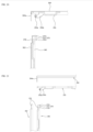
- FIG. 1 is a perspective view of a refrigerator having an anti-loosening device of a raising/lowering device thereof according to the present invention
- FIG. 2 is a sectional view of the refrigerator illustrating a state of a container moved upward by a raising/lowering device according to the embodiment of the present invention.
- the refrigerator 1 is formed to have a predetermined volume as a hexahedron as a whole and is provided with a storage chamber for storing food therein.
- the refrigerator includes: a cabinet 10 provided with a space including the storage chamber therein and an open surface thereof (a front thereof); and at least one door 20 covering the open surface (the front) of the cabinet 10.
- a cooling device (not shown) is provided in the refrigerator 1 to cool the storage chamber.
- the cabinet 10 of the refrigerator 1 is configured such that the front thereof is open, and the door 20 covers the front of the cabinet 10.
- An inner part of the cabinet 10 is preferably partitioned into multiple spaces. That is, a space of the storage chamber provided in the cabinet 10 is divided by at least one inner wall 30. In the present invention, the space is divided into upper and lower spaces by the parallel inner wall 30.
- the cabinet 10 includes an upper space 32 on an upper side thereof and a lower space 34 provided on a lower side thereof relative to the inner wall 30.
- the upper space 32 is used as a refrigerating compartment and the lower space 34 is used as a freezer compartment.
- the upper space 32 and the lower space 34 may be exchanged, all of the upper space 32 and the lower space 34 may be used as a refrigerating compartment, or all of the upper space 32 and the lower space 34 may be used as a freezer. Accordingly, the upper space 32 and the lower space 34 may be designed to be used as a freezer or a refrigerating compartment and may be designed to be used for other purposes when required.
- the upper space 32 includes a swinging door 22, and the lower space 34 includes drawers 24 and 26.
- the lower space 34 is divided into two inner spaces, and the two drawers 24 and 26 are arranged horizontally in the two spaces, respectively. Accordingly, of the drawers 24 and 26, the drawer covering an upper space is an upper drawer 24 and the drawer covering a lower space is a lower drawer 26.
- the number of the doors may be variously changed depending on an inner space of the cabinet 10, and the doors may be provided entirely as the swinging doors 22 or entirely as the drawers 24 and 26.
- the drawers 24 and 26 may be configured to be automatically moved forward or backward by an opening/closing device 100.
- such drawers 24 and 26 are provided with the raising/lowering device 200, which will be described hereinbelow, such that the container 40 provided therein is automatically moved upward and downward.
- a portion or all of the drawers 24 and 26 may be configured to automatically move forward and backward. That is, all of the upper drawer 24 and the lower drawer 26 may be configured to automatically move forward and backward, or the upper drawer 24 may be configured to manually move forward and backward and the lower drawer 26 may be configured to automatically move forward and backward.
- the opening/closing device 100 is provided to have a rack-pinion structure and forces the drawer 26 to move forward and backward (to opposite sides of FIG. 2 ).
- a rack 110 is provided on a lower surface of the lower drawer 26 and the pinion 120 meshing with the rack 110 by gear engagement is rotatably provided in a bottom surface of the refrigerator 1.
- a motor 130 is provided on a bottom surface of the refrigerator 1 and supplies a rotational force to the pinion 120.
- the motor 130 when the motor 130 generates the rotational force by using power supplied from the outside, the pinion 120 is rotated clockwise or counterclockwise by the rotational force. Accordingly, the lower drawer 26 combined with the rack 110 moves forward and backward (to the opposite sides of FIG. 2 ).
- the refrigerator 1 includes a machine room 60 provided at a lower rear side thereof.
- a compressor and a condenser performing a refrigeration cycle may be arranged in the machine room 60.
- FIGS. 3 and 4 a state of the lower drawer 26 of the drawers 24 and 26, which is completely opened forward (to a left side of FIG. 3 ), is illustrated. That is, as illustrated in FIG. 3 , the lower drawer 26 is completely opened forward, and the raising/lowering device 200 does not operate yet, and as illustrated in FIG. 4 , while the lower drawer 26 is completely opened forward, the container 40 is moved upward by the raising/lowering device 200.
- the lower drawer 26 is moved forward (to a left side of FIGS. 3 and 4 ) by a forward moving control by the button 50.
- the forward movement of the lower drawer 26 is performed by the opening/closing device 100.
- Such a lower drawer 26 is not configured to be opened and closed by a manual manipulation of a user, but preferably, the lower drawer 26 is automatically opened and closed by a manipulation of a user pressing the button 50. That is, when a user presses the button 50, the rotational force is generated by the motor 130, and the pinion 120 is rotated counterclockwise by the rotational force.
- a distance which the lower drawer 26 moves to be open to the left is a length allowing the container 40 received into the storage room 27 to be completely exposed to the outside from the front surface of the refrigerator 1. That is, the lower drawer 26 is required to be sufficiently opened such that a user takes out the container 40, or takes out or stores food in the container 40.
- the container 40 is moved upward by the raising/lowering device 200 provided at a lower side of the container 40. Even in this case, the lower drawer 26 is required to be sufficiently opened such that the container 40 does not hit the front surface of the refrigerator 1, that is, a lower end of a front surface of the upper drawer 24.
- the structure having the pinion 120 and the rack 110 may include the double rack structure.
- Whether the lower drawer 26 is sufficiently open is determined by an open/close detecting means 150.
- the open/close detecting means 150 detects whether the lower drawer 26 is sufficiently open to the outside (the left side of FIG. 3 ), and preferably includes permanent magnets 152 and 154, and a detection sensor 156.
- the permanent magnets 152 and 154 are fixed to a left end (a front end of the lower surface of the lower drawer) of the lower surface of the lower drawer 26 and a right end thereof (a rear end thereof), respectively, and the detection sensor 156 is fixed to a front end part of the bottom surface of the refrigerator 1.
- the permanent magnets 152 and 154 include a front end magnet 152 provided at the left end (the front end) of the lower surface of the lower drawer 26 and a rear end magnet 154 provided at the right end (the rear end) of the lower drawer 26.
- the lower drawer 26 is recognized to be closed and when the rear end magnet 154 is brought close to the detection sensor 156, the lower drawer 26 is recognized to be opened.
- the detection sensor 156 may be various sensors such as a hall sensor or a lead switch.
- the inner cover 300 is installed to have a section of an "L" shape as a whole and covers the remaining rear end space of the inner space of the storage room 27 except for a space corresponding to an occupying space of the container 40 in the inner space thereof.
- the rear end space in the storage room 27 is covered by the inner cover 300, whereby a neat appearance is provided to a user and a hand of the user is prevented from being trapped therein.
- the raising/lowering device 200 is configured to be folded or unfolded in an upper end and lower end thereof, and when the raising/lowering device is not used, volume thereof is minimized, so the raising/lowering device 200 is preferably received in the storage room 27. That is, the raising/lowering device 200 may be configured to have a scissor type link structure in which the height of the raising/lowering device 200 is minimized during the folding of the raising/lowering device 200 and the height of the raising/lowering device 200 is maximized during the unfolding of the raising/lowering device 200.
- the storage room 27 is configured to have the containing space of a predetermined size therein so as to constitute an outer surface thereof.
- the storage room 27 is provided with the raising/lowering device 200 therein such that the container 40 or food is moved upward and downward.
- the inner cover 300 is provided in the storage room 27 so as to cover the rear end part of the inner part of the storage room 27 and to partition the inner space of the storage room 27.
- the storage room 27 may be formed of plastic materials by injection molding to have an entire shape thereof.
- the storage room 27 has a shape of a basket having an open upper surface to have a space therein to allow food to be stored.
- An outer side plate 27a is provided on each of opposite surfaces of outer sides of the storage room 27.
- the outer side plate 27a is installed on each of the opposite surfaces of the storage room 27 to constitute outer surfaces thereof.
- the outer side plate 27a also functions such that components such as a door frame (not shown) mounted to each of opposite sides of a drawer body 38 and the rack 110 constituting the opening/closing device 100 are not exposed to the outside.
- the inner cover 300 is provided to divide the inner part of the storage room 27 into a front space and a rear space.
- the inner cover 300 includes a front surface cover 310 and an upper surface cover 320.
- the front surface cover 310 is formed in a step shape and partitions an inside space of the storage room 27 into a front space and a rear space, and the upper surface cover 320 is rotatably connected to an upper end of the front surface cover 310 and covers a rear upper surface of the front surface cover 310.
- the inner cover 300 includes the front surface cover 310 forming a vertical surface and the upper surface cover 320 formed horizontally by extending and rearward from the upper end of the front surface cover 310.
- the upper surface cover 320 is preferably connected to the upper end of the front surface cover 310 to be rotatable.
- the front surface cover 310 has the step shape lower end portion, and the step shape portion functions to prevent a user's finger from being inserted into a lower side of the drawer through a gap between the raising/lowering device 200 and the front surface cover 310.
- An outer surface of the inner cover 300 may be preferably made of a metal material as the outer side plate 27a. This is to allow a user to feel the texture of metal and create aesthetic qualities and have rigidity since the inner cover 300 is a part seen during the forward movement of the lower drawer 26 by the user.
- a front surface and side surfaces of the storage room 27 may also be made of a metal material. Accordingly, when each part of the storage room 27 is made of the metal material, inner sides of the containing space of the storage room 27 may entirely have the feel of metal, food stored therein may be stored to be entirely and evenly cold, and visually aesthetic qualities may be created for a user.
- the raising/lowering device 200 sits in the inner part of the storage room 27.
- the raising/lowering device 200 has a structure of being vertically moved upward and downward by the driving device 400 connected thereto, which will be described, and preferably, opposite sides of the raising/lowering device move upward and downward at the same rate
- connection hole 27b is provided at each of lower opposite sides of the front surface of the storage room 27 by being formed therethrough in a front to rear direction of the front surface.
- connection hole 27b is a part into which the scissor side connection part 250 provided at the front end of the raising/lowering device 200 is inserted to be received therein. Accordingly, a radius of the connection hole 27b is preferably configured to be the same as or larger than a radius of the scissor side connection part 250.
- FIGS. 6 to 10 the configuration of the raising/lowering device 200 is illustrated. That is, in FIG. 6 , a perspective view of configuration of the raising/lowering device is illustrated, and in FIGS. 7 and 8 , a front view and a right side view of the raising/lowering device 200 are illustrated. In addition, in FIG. 9 , a perspective view of a state of the raising/lowering device 200 from which a support plate 210 is removed is illustrated, and in FIG. 10 , a right side sectional view of the raising/lowering device 200 is illustrated.
- the raising/lowering device 200 which is configured to be a scissor type, is folded when the raising/lowering device is lowered and is unfolded when the raising/lowering device is raised such that the container 40 or food seated on the upper surface thereof is moved upward and downward.
- the raising/lowering device 200 is provided with the support plate 210 thereon. That is, as illustrated in the accompanying drawings, the support plate 210 is provided on an upper end of the raising/lowering device 200 to allow the container 40 laid on an upper side thereof to be efficiently seated.
- the support plate 210 which constitutes an outer surface of the upper surface of the raising/lowering device 200, is configured to have a predetermined thickness and may be made of a metal such as a stainless material to be aesthetic, and is preferably configured such that an inner part of the support plate is depressed so as to allow the container 40 to be efficiently seated and fixed.
- the raising/lowering device 200 may be provided on an inner bottom of the storage room 27 and, preferably, is removably provided at an inner side of the storage room 27.
- the raising/lowering device 200 includes the upper frame 220 provided at the upper side thereof, a lower frame 230 provided under the upper frame 220, and a pair of scissor assemblies 240 arranged between the upper frame 220 and the lower frame 230.
- the upper frame 220 is configured to have a rectangular frame shape, and the support plate 210 sits on and is fixed to an upper surface of the upper frame 220.
- the upper frame 220 of the raising/lowering device 200 moves in upward and downward directions and substantially supports food or the container 40 together with the support plate 210.
- the upper frame 220 may be configured to have a metal plate shape, and edges thereof are partially bent downward. Accordingly, the upper frame 220 is preferably configured to define a space to house each of the scissor assemblies 240 in cooperation with the lower frame 230.
- the lower frame 230 is provided under the upper frame 220 and sits on a bottom surface of the storage room 27. Furthermore, the lower frame 230 is preferably configured to have a shape corresponding to a shape of the upper frame 220.
- the lower frame 230 may also be configured to have a metal plate shape as the upper frame 220, and edges thereof are bent upward. Accordingly, the lower frame 230 is preferably configured to define the space to house each of the scissor assemblies 240 together with the upper frame 220.
- the raising/lowering device 200 is configured to be unfolded or folded upward and downward by the scissor assemblies 240. Accordingly, to allow the raising/lowering device 200 to be folded, a locking means 500 is required.
- the locking means 500 allows the lower frame 230 and the upper frame 220 to be brought close to each other to vertically fold the raising/lowering device 200 such that a vertical length of the locking means is minimized.
- the locking means 500 includes the upper locking means 510 provided in the upper frame 220 and the lower locking means 520 provided in the lower frame 230.
- the lower locking means 520 is provided at a middle of the lower frame 230.
- the lower locking means 520 functions to allow the upper frame 220 and the lower frame 230 to be not randomly separated from each other and to be in a state of restricting each other when the raising/lowering device 200 is removed from the storage room. That is, the lower locking means 520 allows the scissor assemblies 240 to maintain the folded state thereof without unfolding.
- the lower locking means 520 includes a locking means casing 522 fixed to the middle of the lower frame 230, a lower hook 530 moving in the locking means casing 522, and a force applying member 524 applying a unidirectional force to the lower hook 530.
- the lower locking means 520 is provided at the middle of an upper surface of the lower frame 230 by protruding upward therefrom.
- the locking means casing 522 is configured to have a predetermined front to rear length (to opposite sides of FIG. 10 ) and a hook space 526 having volume of a predetermined size is provided in the locking means casing 522.
- the lower hook 530 includes a hook body 532 having a predetermined vertical height, a support end 534 provided at a lower end of the hook body 532 to support the hook body 532, and a hook end 536 protruding by extending forward from an upper end of the hook body 532.
- the hook body 532 is configured to have the predetermined vertical height and a hook hole 532a is provided in an upper surface of the locking means casing 522 by being vertically formed therethrough. That is, the hook hole 532a having a predetermined front to rear length is provided in the upper surface of the locking means casing 522 by being vertically formed therethrough, and the hook body 532 is arranged by vertically passing through the hook hole 532a.
- the front to rear length of the hook hole 532a is configured to have a size larger than a size of the thickness of the hook body 532 provided to pass through the hook hole 532a. Accordingly, the hook body 532 is allowed to move a predetermined distance forward and backward while the hook body 532 is received in the hook hole 532a.
- the support end 534 is configured to extend forward and backward (to opposite sides of FIG. 10 ) at a lower end of the hook body 532 and vertically extend therefrom and is a part moving forward and backward (to the opposite sides of FIG. 10 ) in the locking means casing 522.
- the hook end 536 is provided to protrude by a predetermined portion by perpendicularly bending to a front (a left side of FIG. 10 ) of the hook body 532 from the upper end thereof and has a shape corresponding to a shape of an upper hook end 514 of the upper locking means 510, which will be described hereinbelow.
- the force applying member 524 is provided in the locking means casing 522 and functions to pull the lower hook 530 forward (to the left side of FIG. 10 ). More particularly, the force applying member 524 is configured as a tension spring and functions to pull the lower hook 530 forward by tensile elasticity.
- a front of the force applying member 524 is connected to a front surface of an inner side of the locking means casing 522 and a rear end of the force applying member is connected to a front end of the support end 534.
- the force applying member 524 may be made of various materials as long as the force applying member has function of pushing or pulling the lower hook 530 forward by the elasticity.
- the force applying member 524 may be provided as an elastic spring and installed at a rear side of the support end 534 to push the lower hook 530 forward by an elastic force.
- the upper frame 220 includes the upper locking means 510 provided on a middle portion of a lower surface of the upper frame.
- the upper locking means 510 is provided by protruding downward from the lower surface of the upper frame 220 and has a shape corresponding to a shape of the lower hook 530 such that the upper locking means and the lower hook are engaged with each other. That is, a lower end of the upper locking means 510 is bent perpendicularly rearward (to the right side of FIG. 10 ), thereby being held by the hook end 536 of the lower hook 530.
- the raising/lowering device 200 is required to freely fold and unfold, but when the raising/lowering device 200 is removed upward from the storage room, the raising/lowering device 200 is required to maintain the folded state thereof. That is, the raising/lowering device 200 is required to unfold when the container 40 sits on an upper side of the raising/lowering device 200 to be moved upward and downward. However, when the raising/lowering device 200 is removed to the outside since the raising/lowering device is not used, the raising/lowering device 200 is required to be removed upward with the raising/lowering device folded.
- the raising/lowering device 200 is naturally rotated relative to the front end thereof. Accordingly, the lower locking means 520 escapes from the spacing protrusion 27c, which will be described hereinbelow, and the folded state of the raising/lowering device 200 is maintained by the locking means 500.
- the scissor assemblies 240 are provided at opposite sides of the upper frame 220 and the lower frame 230 relative to a middle of each of the upper frame and the lower frame.
- each of the scissor assembly 240 is axially coupled to the upper frame 220 and the lower frame 230. Accordingly, the upper frame 220 may move upward and downward according to the movement of the scissor assembly 240.
- the plate unit 242 is rotatably mounted to the lower frame 230. That is, the plate unit 242 is rotatably installed at each of opposite ends of the lower frame 230.
- the rod unit 244 is rotatably connected to the upper frame 220. That is, preferably, the rod unit 244 is rotatably installed at each of opposite ends of the upper frame 220.
- the plate unit 242 may be configured to be a rectangular plate shape and be made of aluminum alloy materials. Accordingly, the plate unit may be formed to have high rigidity and be light, and may also be formed by die casting.
- the plate unit 242 includes the scissor side connection part 250 provided at a lower end thereof by protruding therefrom. That is, the scissor side connection part 250 is provided at a front end of the plate unit 242 by further protruding forward to be integrated with the plate unit.
- the rod unit 244 is preferably installed to intersect the plate unit 242. That is, the rod unit 244 and the plate unit 242 unfold to have an "X" shape (as viewed from a front thereof) by intersecting each other, and an intersecting shaft 246 is provided at a center portion at which the rod unit 244 and the plate unit 242 intersect each other such that the rod unit 244 and the plate unit 242 rotatably intersect each other.
- rod unit 244 and the plate unit 242 are in contact with the lower surface of the upper frame 220 and the upper surface of the lower frame 230 and accordingly, the rod unit 244 and the plate unit 242 are preferably configured to slidably move.
- a lower end (in FIG. 6 ) of the plate unit 242 is rotatably mounted to the lower frame 230 and an upper end of the plate unit 242 is installed on the lower surface of the upper frame 220 to slidably move.
- an upper moving guide 252 is provided on the lower surface of the upper frame 220 to have a predetermined length to opposite sides thereof and is in contact with the upper end of the plate unit 242 to guide the plate unit such that the plate unit slidably moves.
- a roller rotating along the upper moving guide 252 is provided at the upper end of the plate unit 242.
- An upper end (in FIG. 6 ) of the rod unit 244 is rotatably mounted to each of the opposite ends of the upper frame 220, and a lower end of the rod unit 244 is slidably installed on the upper surface of the lower frame 230.
- a lower moving guide 254 is installed on the upper surface of the lower frame 230 to have a predetermined length to opposite sides thereof and is in contact with the lower end of the rod unit 244 so as to guide a sliding movement of the rod unit.
- a roller rotating along the lower moving guide 254 may be provided at the lower end of the rod unit 244.
- the rear end hook 260 is held by a lower end of the inner cover 300 and the cover piece 270 covers a gap between the raising/lowering device 200 and the inner cover 300.
- the handle 215, which will be described hereinbelow, is preferably provided at each of rear end parts of the opposite side edges of the support plate 210.
- FIG. 11 is a perspective view illustrating configuration of a driving device 400
- FIGS. 12 and 13 are a rear perspective view and a front perspective view, respectively, illustrating a state at which the driving device 400 and the raising/lowering device 200 are connected to each other.
- the driving device 400 is preferably arranged in the front panel 28 and is connected to the raising/lowering device 200 provided at a rear side thereof. Accordingly, power generated by the driving device 400 is transmitted to the raising/lowering device 200.
- the driving device 400 transmits power simultaneously to the opposite sides of the raising/lowering device 200. Accordingly, preferably, the raising/lowering device 200 moves upward and downward in parallel in the opposite sides thereof without slanting.
- the driving device 400 includes a motor assembly 410, a screw unit 420 arranged at each of opposite sides of the motor assembly 410 to have a pair of screw units, and a lever 430 connected to each of the screw units 420 to have a pair of levers.
- the screw unit 420 includes a screw 422 and the screw holder 424, through which the screw 422 passes, moving upward and downward along the screw 422.
- a lever connection part 432 is provided at an end of the lever 430 and the lever connection part 432 is rotatably fixed to a rear surface of the front panel 28.
- the lever connection part 432 is combined with the scissor side connection part 250.
- a lever hole 434, into which a holder engaging member 440 is locked, may be provided in an inner end of each of the pair of the levers 430.
- the lever hole 434 which is configured to be a longitudinal hole, guides movement of the holder engaging member 440 and at the same time allows the holder engaging member 440 to be engaged with the screw holder 424. Accordingly, the lever 430 is rotated by the screw holder 424 moving upward and downward during rotation of the screw 422.
- the motor assembly 410 is positioned at a middle portion of the front panel 28.
- a drive motor 412 is provided in the motor assembly 410 and the screw units 420 and the levers 430 of the opposite sides of the motor assembly 410 are operated by the motor assembly 410 including the drive motor 412.
- the motor assembly 410 allows speed reduction and a magnitude of a transmitted force to be adjusted by combination of multiple gears.
- the motor assembly 410 has a structure of having the drive motor 412 and the gears vertically arranged so as to minimize a recessed space of the front panel when the motor assembly 410 is installed in the front panel 28.
- a width of opposite side directions thereof is preferably configured to be wide and a thickness of forward and backward directions thereof is configured to be minimized.
- the power transmission part is configured by the combination of the multiple gears and is covered by a cover member 450 mounted at a side (a front of the motor casing) opposite to the side of the drive motor 412.
- the second transmission gear 456 meshing with the first transmission gear 454 is preferably configured as a multi-stage gear to mesh with the upper and lower gears each other.
- the cross gears 460 are configured to include spur gears and helical gears.
- a first helical gear part (not shown) is provided at a rear of each of the cross gears 460 configured to have a spur gear shape, and the first helical gear part meshes with a second helical gear part 464 of a side of each of the cross gears.
- a rotation center line of the second helical gear part 464 is arranged to intersect a rotation center line of the cross gear 460. Accordingly, the first helical gear part (not shown) and the second helical gear part 464 are combined with each other in a state intersecting with each other and are configured to be engaged with each other so as to allow rotations thereof to be transmitted to each other.
- the motor assembly 410 may be arranged between the screw units 420 positioned at the opposite sides, and each of the screw units 420 arranged at the opposite sides is arranged to have a shorter distance therebetween toward a lower end thereof from an upper end thereof.
- the screw unit 420 includes the screw 422 rotated by receiving the power of the drive motor 412, wherein the screw 422 extends in upward and downward directions and is configured to be inclined such that an upper end thereof faces an outside thereof and a lower end thereof faces an inside thereof.
- the screw 422 is connected to the second helical gear part 464. Accordingly, the screw 422 rotates together with the second helical gear part 464 during rotation thereof.
- a magnet may be provided in the screw holder 424.
- the magnet is provided such that a position of the screw holder 424 is detected and when the screw holder 424 is positioned at a lowest end or a top end of the screw 422, the raising/lowering detection means (not shown) detects this. That is, completion of an upward or downward movement of the raising/lowering device can be determined by whether the magnet installed in the screw holder 424 is detected.
- the lever 430 connects the screw holder 424 with the raising/lowering device 200 and each of opposite sides of the lever is combined with each of the screw holder 424 and the raising/lowering device 200.
- the screw unit 420 may further include a housing 426 receiving the screw unit 420.
- the housing 426 is provided with at least one guide bar 428 to guide lifting of the screw holder 424.
- the at least one guide bar 428 extends in parallel with the screw 422 while being spaced apart from the screw 422.
- the motor casing 414 and a pair of housings 426 may be provided to be integrated with each other. Furthermore, a single cover member 450 may cover the motor casing 414 and the pair of housings 426. That is, the cover member 450 is combined with the motor casing 414 to cover the power transmission part, and is combined with the pair of housings 426 to cover the screw 422, the guide bars 428, and the screw holder 424.
- the driving device 400 exists as a module, the driving device 400 becomes compact and thus the driving device 400 can be easily installed in the front panel 28.
- FIG. 14 is a perspective view of a state of the raising/lowering device folded according to the embodiment of the present invention.
- the support plate 210 constitutes an upper outer surface of the raising/lowering device 200.
- the support plate 210 is a rectangular flat plate as a whole, and each of edges thereof protrudes upward to have a predetermined height. Accordingly, the upper surface of the support plate 210 is entirely formed such that an inner part of each of the edges thereof is depressed, so that a lower end of the container 40 is easily seated.
- the edges of the support plate 210 include a front edge 212 provided by protruding upward from an upper surface of a front end thereof, side edges 214 provided by protruding upward from opposite sides thereof, and a rear edge 216 provided by protruding upward from an upper surface of a rear end thereof.
- the handle 215 is a part held by fingers of a user when the user takes out the raising/lowering device 200 from the inner part of the storage room 27.
- the handle 215 is preferably configured to be recessed from an inner surface of each of the pair of the opposite side edges 214 to an outer side thereof. Accordingly, a user moves his/her fingers from a middle of the upper surface of the support plate 210 to each of the pair of side edges 214, puts his/her fingers in the recessed portion of the handle 215, and lifts the raising/lowering device upward.
- the raising/lowering device 200 rotates relative to the front end thereof and the rear end part thereof is lifted upward.
- FIG. 15 is a sectional view of a state of the raising/lowering device 200 mounted in the storage room 27, and FIG. 16 is a partial sectional view illustrating a state at which the raising/lowering device 200 mounted in the storage room 27 is lifted upward.
- the raising/lowering device 200 sits on the bottom surface of the inner part of the storage room 27.
- the scissor side connection part 250 of the raising/lowering device 200 passes through the connection hole 27b of the storage room 27 and accordingly, a front end of the scissor side connection part 250 protrudes to the front (a left side of FIG. 15 ) of the storage room 27.
- the lower hook 530 moves backward (a right side of FIG. 15 ) and is separated from the upper locking means 510. Accordingly, the upper frame 220 and the lower frame 230 are not locked to each other in the folded state.
- the storage room 27 includes the spacing protrusion 27c provided at a middle part thereof by protruding upward therefrom, and the lower hook 530 is moved backward (the right side of FIG. 15 ) by the spacing protrusion 27c.
- the spacing protrusion 27c is preferably configured to have a " ⁇ " shape having a pointed upper side. Particularly, although a front surface (a left-side surface of FIG. 15 ) of the spacing protrusion 27c may be vertically configured, a rear surface thereof (a right-side surface of FIG. 15 ) is required to be configured slantingly.
- the upper locking means 510 and the lower hook 530 of the raising/lowering device 200 are engaged with each other to maintain the folded state thereof outside of the storage room 27. Accordingly, when the raising/lowering device 200 of the folded state is installed on the bottom surface from an upper part of the storage room 27, the raising/lowering device 200 is brought into a close contact with the bottom surface of the storage room 27 by weight.
- the rear surface of the spacing protrusion 27c is in contact with a rear end of a lower surface of the hook body 532 of the lower hook 530.
- the elasticity of the force applying member 524 configured as the tension spring does not overcome a downward moving force of the raising/lowering device 200, and accordingly, the rear end of the lower surface of the hook body 532 of the lower hook 530 gradually slides along the rear surface of the spacing protrusion 27c as illustrated in FIG. 15 .
- the spacing protrusion 27c is received in the protrusion groove 532b provided in the hook body 532, and the lower hook 530 and the upper locking means 510 are spaced apart from each other and accordingly are not engaged with each other.
- the spacing protrusion 27c is received in the protrusion groove 532b, and the lower locking means 520 and the upper locking means 510 are separated from each other such that the locking means 500 is unlocked. Accordingly, the raising/lowering device 200 is in a state which can be unfolded.
- the handle 215 is lifted upward while the handle is held by each of the hands.
- the raising/lowering device 200 When the rear end of the raising/lowering device 200 moves up, the raising/lowering device 200 slants gradually. Since the force applying member 524 is the tension spring, the force applying member continuously pulls the lower hook 524 forward. Accordingly, the lower hook 524 moves forward while moving upward gradually and thus is engaged with the upper locking means 510.
- the raising/lowering device 200 is maintained at the folded state and the scissor side connection part 250 deviates from the connection hole 27b of the storage room 27. Accordingly, the raising/lowering device 200 is completely removed from the upper side of the storage room 27.
- FIG. 17 is an exploded-perspective view illustrating configuration of the inner cover 300 separated from the storage room 27 according to the embodiment of the present invention.
- the inner cover 300 functions to cover the rear end portion of the inner space of the storage room 27.
- the inner cover 300 is provided with the front surface cover 310 and the upper surface cover 320.
- the front surface cover 310 partitions the inner space of the storage room 27 into the front space and the rear space and is formed in a step shape, and the upper surface cover 320 is rotatably connected to the upper end of the front surface cover 310 and covers the rear upper surface of the front surface cover 310.
- the front surface cover 310 is preferably provided with the upper end portion 312, the step surface 314, and the lower end portion 316.
- the upper end portion 312 is provided for rotatable connection of the upper surface cover 320
- the step surface 314 is formed by being bent perpendicularly forward from the lower end of the upper end portion 312 and extending
- the lower end portion 316 is formed by being bent perpendicularly downward from the end of the step surface 314.
- the inner cover 300 includes a main member 330 forming a frame of the inner cover 300 and an exterior material 360 forming an exterior of the inner cover 300.
- the main member 330 is made of an injection molded article by injection molding, and an entire shape thereof is molded in a' ' shape (shown from right side).
- the exterior material 360 is coupled to each of a front surface and an upper surface of the main member 330 to form appearance of the front and upper surfaces thereof.
- the exterior material 360 is formed of metal material or a clad material. That is, the exterior material 360 is formed to cover the front and upper surfaces of the main member 330 made of the injection molded article and functions to form a neat appearance. Accordingly, the exterior material 360 is preferably formed of a material that creates a luxurious texture.
- the metal material is excellent in gloss and easy to be deformed and are frequently used in household goods and interior products.
- surfaces of the products may be coated or painted separately.
- the clad material is advanced new materials that combine several different metals together to take advantage of each metal. Among them, it is preferable to use a material in which aluminum having excellent thermal conductivity, heat preservation rate, and thermal efficiency is combined with stainless steel having excellent flame resistance, acid resistance, alkali resistance, and corrosion resistance.
- the main member 330 includes a front surface member 340 and an upper surface member 350.
- the front surface member 340 is installed vertically inside the storage room 27, and the upper surface member 350 is rotatably connected to an upper end of the front surface member 340 and covers a rear upper end of the front surface member 340.
- the exterior material 360 preferably includes a front exterior material 362 and an upper exterior material 364.
- the front exterior material 362 is installed in close contact with a front surface of the front surface member 340 and the upper exterior material 364 is installed in close contact with an upper surface of the upper surface member 350.
- the front exterior material 362 is preferably provided as a separate structure from the upper exterior material 364. That is, preferably, the front exterior material 362 and the upper exterior material 364 are configured separately from each other and are respectively installed to cover the front surface of the front surface member 340 and the upper surface of the upper surface member 350.
- a locking end 332 is provided on a lower end of the front surface member 340.
- the locking end 332 is a portion where the rear end hook 260 is held and fastened. Accordingly, the locking end 332 is preferably provided with a hook hole 332a penetrating vertically. That is, the rear end hook 260 is inserted into the hook hole 332a provided in the locking end 332.
- the hook hole 332a is formed by penetrating the locking end 332 vertically, but may be formed in a groove shape on the locking end 332. That is, the hook hole 332a may be formed in a groove depressed downward from an upper surface of the locking end 332.
- a bump 334 is provided on an inner side surface of the storage room 27 for preventing rearward movement of the inner cover 300. That is, on left and right inner side surfaces of the storage room 27, a pair of preventing steps 334 is formed to face each other.
- each of the preventing steps 334 is preferably formed on an upper half portion of the inner side surface of the storage room 27 with a predetermined length up and down.
- the bump 334 is preferably formed to have elasticity. That is, preferably, the bump 334 is integrally formed with the inner side surface of the storage room 27 which is formed of the same material of the exterior material 360 of the inner cover 300, and a part of the inner side surface of the storage room 27 protrudes inward to form the bump 334.
- the bump 334 has elasticity to be moveable from side to side. That is, the bump 334 may have elasticity by a shape or a material thereof, and may be configured to be moveable from side to side by elasticity of the inner side surface of the storage room 27 which is integrally formed therewith.
- the preventing steps 334 are retracted leftward and rightward by elasticity and the front surface cover 310 is moveable rearward.
- the bump 334 is designed to be retracted leftward and rightward so that an upper end of the front surface cover 310 is moved rearward.
- the front surface cover 310 When the upper half portion of the front surface cover 310 is moved rearward by passing through the bump 334, the front surface cover 310 is rotated clockwise to be in close contact with a rear surface 27a of the storage room 27 because a lower end of the front surface cover 310 is fixed to be rotatable.
- the bump 334 is preferably formed by protruding to interfere with a side surface of the inner cover 300.
- the bump 334 preferably protrudes inward by an amount that interferes with the side surface of the front surface cover 310 of the inner cover 300. That is, since the bump 334 functions to prevent rearward movement of the front surface cover 310 of the inner cover 300, when the bump 334 is installed not to contact with the side surface of the front surface cover 310, the function thereof is lost.
- the bump 334 protrudes to overlap the side surface of the inner cover 300 by at least 0.5mm. This is for user convenience. That is, if necessary, the user may push the inner cover 300 rearward to closely contact the rear surface of the storage room 27 and use the entire inner space of the storage room 27 as a storage space.
- the front surface cover 310 does not pass over the bump 334 when the user pushes the front surface cover 310 rearward.
- the bump 334 overlaps the side surface of the inner cover 300 by a side less than 0.5mm (equal to or less than 5mm)
- the front surface cover 310 falls rearward by passing over the bump 334, even when the user grasps the raising/lowering device 200 or only touches the front surface cover 310 during operation of putting food into the storage room 27 or taking out food in addition to the case of pushing the front surface cover 310 rearward. Therefore, there may be a safety accident or may be inconvenient to use.
- a fastening end 70 is provided in the step shape on a rear end of the storage room 27, that is, on an upper end of the rear surface 27a.
- the fastening end 70 has at least one fastening bar 72.
- the fastening end 70 is a portion where a rear end of the upper surface cover 320 of the inner cover 300 is seated, and the fastening bar 72 is a portion fitted into a cover fastening member 354, which will be described hereinbelow.
- At least one guide 80 is provided in an upward protruding shape in rear of the fastening end 70, and guides a position where the rear end of the upper surface cover 320 is mounted.
- the front exterior material 362 and the upper exterior material 364 are preferably provided as separate structures. That is, preferably, the front exterior material 362 and the upper exterior material 364 are formed separately from each other, and are respectively installed to cover the front surface of the front surface member 340 and the upper surface of the upper surface member 350. As illustrating in the drawings, the front exterior material 362 and the upper exterior material 364 are respectively formed in shapes corresponding to the front surface member 340 and the upper surface member 350 of the main member 330. That is, the front exterior material 362 is formed vertically in the step shape like the front surface member 340 and the upper exterior material 364 is formed of a flat plate having a predetermined width like the upper surface member 350.
- the lower end of the inner cover 300 is rotatably coupled to the bottom surface of the storage room 27.
- the lower end of the inner cover 300 has at least one cover hinge 348, which will be described hereinbelow, and the bottom surface in the storage room 27 is provided with a hinge receiving part 27d, which will be described hereinbelow, to rotatably support the cover hinge 348.
- the cover hinge 348 includes a support end 348a and a hinge shaft 348b, which will be described hereinbelow.
- the support end 348a is formed by extending perpendicularly rearward from the lower end of the inner cover 300, and the hinge shaft 348b is formed in a slender round bar shape at a rear end of the support end 348a.
- FIG. 18 is a perspective view illustrating the main member 330.
- the main member 330 includes the front surface member 340 installed vertically and the upper surface member 350 installed horizontally by being rotatably hinge-coupled to the upper end of the front surface member 340.
- the front surface member 340 is formed in the step shape like the front surface cover 310 described above, as illustrated in FIG. 18 . That is, the front surface member 340 includes a main upper end portion 342, a main step surface 344, and a main lower end portion 346.
- the main upper end portion 342 is provided to allow the upper surface member 350 to be rotatably connected
- the main step surface 344 is formed by being bent perpendicularly forward from a lower end of the main upper end portion 342 and extending
- the main lower end portion 346 is formed by being bent perpendicularly downward from an end of the main step surface 344 and extending.
- the locking end 332 is formed by protruding forward from a lower end of the main lower end portion 346 of the front surface member 340, and the locking end 332 has the hook hole 332a described above.
- the main lower end portion 346 of the front surface member 340 is provided with the cover hinge 348 at the lower end thereof.
- the cover hinge 348 includes the support end 348a formed by extending perpendicularly rearward from the lower end of the front surface member 340 and the hinge shaft 348b formed at the rear end of the support end 348a.
- the pair of support ends 348a is provided, and the hinge shaft 348b is connected between ends of the pair of support ends 348a.
- the hinge shaft 348b is formed in the slender round bar shape, and is mounted to the hinge receiving part 27d, which will be described hereinbelow.
- the upper surface member 350 is rotatably connected to the upper end of the front surface member 340.
- the upper surface member 350 is configured to be rotated clockwise (in FIG. 18 ) in a connection state to the upper end of the front surface member 340 so as to overlap the front surface member 340.
- the upper surface member 350 has a fastening step 352 protruding downward on a rear end of a lower surface.
- the fastening step 352 is seated in the fastening end 70 formed at the rear end of the storage room 27. That is, the fastening step 352 is seated to contact the front of the fastening end 70 formed in the step shape.
- the fastening step 352 is formed in a width direction of the lower surface of the upper surface member 350, and the cover fastening member 354 is formed in rear of the fastening step 352.
- the cover fastening member 354 is provided so that the fastening bar 72 of the storage room 27 is inserted therein by elasticity.
- the cover fastening member 354 includes a moving protrusion 354a and a fixed protrusion 354b, the moving protrusion 354a is formed such that a part of the fastening step 352 is cut and the fixed protrusion 354b is formed by protruding downward from the lower surface of the upper surface member 350.
- the moving protrusion 354a is formed such that a thickness thereof is gradually increased from an upper end thereof to a lower end thereof and the lower end is positioned further rearward than the upper end.
- the fixed protrusion 354b is formed to face the moving protrusion 354a at a predetermined distance, and is preferably provided such that a thickness thereof is gradually increased from an upper end thereof to a lower end thereof and the lower end is positioned further forward than the upper end.
- the moving protrusion 354a and the fixed protrusion 354b are paired, and are provided so that the fastening bar 72 is inserted therein. Accordingly, the moving protrusion 354a and the fixed protrusion 354b are preferably provided such that a distance therebetween is gradually decreased from the upper side to the lower side, and a lower gap between the moving protrusion 354a and the fixed protrusion 354b is formed to be smaller than an external diameter of the fastening bar 72.
- FIGS. 19 to 21 are sectional views illustrating configuration of the inner cover 300 in detail. That is, FIG. 19 is a right side sectional view of the inner cover 300, FIG. 20 is a sectional view illustrating a state of separating the front surface cover 310 and the upper surface cover 320 from each other, and FIG. 21 is an exploded sectional view illustrating each of the front surface cover 310 and the upper surface cover 320.
- the upper surface cover 320 is hinge-coupled to the front surface cover 310.
- the front surface cover 310 is configured of the front exterior material 362 and the front surface member 340, and the front surface member 340 has a shaft fixing means 370 at the upper end thereof.
- the shaft fixing means 370 is rotatably fixed to the front surface member with receiving a rotation shaft 350a.
- the rotation shaft 350a includes a shaft groove 372 receiving the rotation shaft therein, and an upper rib 374 and the lower rib 376 that are formed at an upper side and a lower side of the shaft groove 372.
- the shaft groove 372 is formed in a semicircular shape and formed to be open rightward.
- the upper rib 374 and the lower rib 376 are formed by being bent perpendicularly rightward from the upper end of the front surface member 340 and extending.
- right ends of the upper rib 374 and the lower rib 376 are formed closer to each other than left ends thereof.
- the right ends of the upper rib 374 and the lower rib 376 are close to each other and formed in a concave shape.
- a distance between the right ends of the upper rib 374 and the lower rib 376 is formed to be smaller than an external diameter of the rotation shaft 350a, which will be described hereinbelow. Accordingly, when the rotation shaft 350a is inserted into the shaft groove 372, the rotation shaft 350a is not removed rightward by elasticity of the upper rib 374 and the lower rib 376.
- Upper ends of the front surface member 340 and the front exterior material 362 are recessed rightward to form a rib groove 378.
- the rib groove 378 is a part where a tip rib 364a of the upper exterior material 364 is seated thereon.
- the upper surface cover 320 is configured of the upper exterior material 364 and the upper surface member 350.
- the rotation shaft 350a is formed by protruding downward on a left end of the upper surface member 350.
- the rotation shaft 350a is formed in the slender round bar shape, is inserted into the shaft groove 372, and is supported by the shaft holder 350b.
- a left end portion of the upper surface member 350 has the shaft holder 350b protruding downward and leftward, the rotation shaft 350a is provided on a left end portion of the shaft holder 350b.
- the upper surface member 350 and the front surface member 340 do not interfere with each other and the upper surface member 350 overlaps to a rear surface of the front surface member 340 (to a right surface in FIG. 20 ).
- the tip rib 364a is provided at an end (left end in FIG. 20 ) of the upper exterior material 364.
- the tip rib 364a is formed by being bent perpendicularly downward from the end of the upper exterior material 364, and is seated on the rib groove 378 that is the upper front surface (left surface in FIG. 20 ) of the front surface cover 310.
- FIG. 22 is a sectional view illustrating a state of an upper end portion of the inner cover 300 fastened to an upper end of the storage room.
- the rear end of the inner cover 300 is coupled to the rear end of the storage room 27. That is, the upper surface cover 320 is provided to cover the upper surface of the rear end of the storage room 27, and the rear end thereof is fixed to the rear end of the storage room 27 by elasticity.
- the guide 80 is provided by protruding upward on the rear end (right end in FIG. 22 ) of the storage room 27.
- the guide 80 protrudes upward higher than the fastening end 70, and guides the rear end (right end in FIG. 22 ) of the upper surface cover 320 not to pass over (right side in FIG. 22 ) the guide 80, when the upper surface cover 320 of the inner cover 300 is mounted (assembled) to the storage room 27.
- the covering means is required for covering the gap between the raising/lowering device 200 and the inner cover 300, and the cover piece 270 may be used as the covering means.
- the cover piece 270 and the step surface 314 are preferably installed to overlap each other up and down. That is, the cover piece 270 is positioned above the step surface 314 that is provided in the front surface cover 310 of the inner cover 300, and preferably, the step surface 314 and the cover piece 270 are provided to overlap each other.
- the raising/lowering device 200 since the raising/lowering device 200 is seated downward due to its own weight, when the height H between the cover piece 270 and the step surface 314 is formed less than 10mm, a child's finger may be pressed between the cover piece 270 and the step surface 314, thereby causing a safety accident.
- the height H of 10mm or more is to prevent the safety accident.
- the lower end of the inner cover 300 is rotatably coupled to the bottom surface of the storage room 27.
- the hinge receiving part 27d is provided to be open upward at the rear end of the bottom surface of the storage room 27. That is, as illustrated in the drawing, the hinge receiving part 27d is formed to have a semicircular inner section and supports the hinge shaft 348b to be removable upward and mountable from above.
- FIG. 24 is a partial cut sectional view illustrating an installation state of each of the front surface cover 310 and the bump 334. That is, the drawing illustrates a partial cut perspective view in which the upper surface cover 320 is rotated on the rotation shaft 350a so that the front surface cover 310, and the upper surface cover 320 are overlap and the bump 334 prevents the rearward movement of the front surface cover 310.
- the bump 334 is formed by protruding inward to interfere with the side surface of the inner cover 300. That is, the bump 334 protrudes inward from the inside surface of the storage room 27 to interfere with the side surface of the inner cover 300.
- the bump 334 is preferably formed by protruding to overlap the side surface of the inner cover 300 by at least 0.5mm. Accordingly, as described above, when the inner cover 300 is pushed over a predetermined force, the inner cover 300 is movable past the bump 334.
Abstract
Description
- The present application claims priority of
KR Appl. No. 10-2019-0084444, filed July 12, 2019 - The present invention generally relates to a refrigerator. More particularly, the present invention relates to a refrigerator configured to prevent a safety accident due to a raising/lowering device moving a container upward and downward.
- Generally, a refrigerator is a home appliance that is provided to store various foods or beverages for a long time by cold air generated by circulation of a refrigerant according to a refrigeration cycle.
- The refrigerator is divided into two types of refrigerators: a common refrigerator that can store storage items a user wants to store regardless of a type of food or drink; and an exclusive-use refrigerator that varies in size or function on the basis of a type of storage item to be stored. The exclusive use refrigerator includes a kimchi refrigerator, a wine refrigerator, and so on. In addition, the refrigerator may be classified into various types depending on a door opening and closing method of a storage chamber in a cabinet, such as a swinging door-type refrigerator, a drawer-type refrigerator, and a hybrid-type refrigerator having both doors and drawers.
- Here, the hybrid-type refrigerator has a structure in which a swinging door is provided in an upper portion of the cabinet and a drawer is provided in a lower portion thereof.
- The drawer provided in the drawer refrigerator or the hybrid-type refrigerator is opened from an inside space of the cabinet in a sliding manner by user's operation. In addition, the drawer is closed by being pushed into the inside space of the cabinet by user's pushing operation, thereby allowing an open front portion of the cabinet to be closed. The drawer includes a front panel and a storage room, the front panel forming a front surface of the refrigerator and being pulled out/pushed in, thereby allowing the inside space of the cabinet to be opened/closed and the storage room being provided in rear of the front panel and received in the inside space of the cabinet. By pulling the front panel, the storage room is opened from the inside space of the cabinet, thus various foods can be stored in and taken out from the storage room.
- Meanwhile, the drawer provided in the drawer refrigerator or the hybrid-type refrigerator is mainly provided in the lower portion of the cabinet. This is because, due to the weight of storage items stored in the storage room of the drawer, the drawer may be removed from the cabinet and fall down forward when the drawer is opened.
- Accordingly, as for the drawer provided at the lower part of the cabinet, a user is required to bend at the waist to take out a container or foods received in the drawer. Accordingly, when the container or the foods are heavy, the heavy container or foods may cause inconvenience or injury when used.
- In order to solve these problems, various structures have been developed in which the drawer can be moved upward and downward. Representatively,
U.S. Patent No. 9,377,238 Korean Patent Application Publication No. 10-2019-0081331 - However, in such a prior art, the lifting mechanism for moving the bin upward and downward has a structure that is disposed outside and exposed to the outside of the bin, so the appearance of the structure is not good and there is a safety accident such as finger trapping in a peripheral gap of a raising/lowering device or a raising/lowering member (container).
Document of Related ArtUS 9,377,238 KR 10-2019-0081331 - The present invention has been made keeping in mind the above problems occurring in the related art, and the present invention is intended to propose a refrigerator, wherein a peripheral gap of a raising/lowering device is blocked.
- In addition, the present invention is intended to propose a refrigerator, wherein a finger of a user is prevented from being inserted into the gap between the raising/lowering device and an inner cover of the storage room.
- In addition, the present invention is intended to propose a refrigerator, wherein even when a child's finger is inserted into the peripheral gap of the raising/lowering device, a safety accident such as trapping and crushing of the finger is prevented.
- In order to achieve the above objects, according to one aspect of the present invention, there is provided a refrigerator that includes a cabinet having a storage chamber therein, a cooling device provided to cool the storage chamber, a drawer provided with a storage room in which a container or food may be stored, a raising/lowering device provided to raise/lower a container storing food, and a covering means provided to cover a peripheral gap of the raising/lowering device.
- In addition, the refrigerator according to the present invention may include a cabinet having a storage chamber therein, a cooling device provided to cool the storage chamber, a drawer provided with a storage room in which a container or food may be stored, a raising/lowering device provided to raise/lower a container storing food, an inner cover provided to cover a rear end portion of an inner space of the storage room
- Preferably, a covering means provided to cover a peripheral gap of the raising/lowering device.
- In addition, the refrigerator according to the present invention may include a cabinet having a storage chamber therein, a cooling device provided to cool the storage chamber, a drawer provided with a storage room in which a container or food may be stored, a raising/lowering device provided to raise/lower a container storing food, an inner cover provided to cover a rear end portion of an inner space of the storage room.
- Preferably, a cover piece may be provided by extending rearward at a rear end of the raising/lowering device so that a gap between the raising/lowering device and the inner cover may be formed less than a predetermined size.
- In addition, the refrigerator according to the present invention may include a cabinet having a storage chamber therein, a cooling device provided to cool the storage chamber, a drawer provided with a storage room in which a container or food may be stored, a raising/lowering device provided to raise/lower a container storing food, and an inner cover provided to cover a rear end portion of an inner space of the storage room.
- Preferably, a cover piece may be provided by extending rearward at a rear end of the raising/lowering device and a front surface of the inner cover may be formed in a step shape, so that the cover piece and a step surface of the inner cover may be configured to overlap up and down.
- In addition, the refrigerator according to the present invention may include a cabinet having a storage chamber therein, a cooling device provided to cool the storage chamber, a drawer provided with a storage room in which a container or food may be stored, a raising/lowering device provided to raise/lower a container storing food, an inner cover provided to cover a rear end portion of an inner space of the storage room.
- Preferably, a bump may be provided at a side surface in the storage room and preventing rearward movement of the inner cover.
- In addition, the refrigerator according to the present invention includes a cabinet having a storage chamber therein and an open front; a cooling device provided at one side of the cabinet and cooling the storage chamber; a drawer provided with a front panel and a storage room, the front panel being pulled out and pushed in so that an open front portion of the storage chamber is opened and closed and the storage room being provided in rear of the front panel and storing a container or food therein; an inner cover provided at the storage room so as to cover a rear end portion of an inner space of the storage room; a raising/lowering device provided in front of the inner cover of the storage room, and configured to fold downward and unfold upward so as to move a container upward and downward in which food is stored.
- Preferably, a covering means may be provided to cover a gap between the raising/lowering device and the inner cover.
- The covering may include a cover piece that is formed by extending rearward from a rear end of the raising/lowering device.
- In addition, a gap between the cover piece and the inner cover may be formed less than 6mm.
- On an upper end of the raising/lowering device, a support plate may be provided to have a shape corresponding to a shape of a lower end of the container so as to support the lower end of the container, and the cover piece may be provided at a rear end of the support plate.
- The inner cover may include: a front surface cover partitioning the inner space of the storage room into a front space and a rear space and formed in a step shape; and an upper surface cover rotatably connected to an upper end of the front surface cover, and covering a rear upper surface of the front surface cover.
- The front surface cover may include an upper end portion at an upper end thereof for rotatable connection of the upper surface cover, a step surface formed by being bent perpendicularly forward from a lower end of the upper end portion and extending, and a lower end portion formed by being bent perpendicularly downward from an end of the step surface and extending.
- In addition, the cover piece and the step surface may be provided to overlap up and down.
- A height between the cover piece and the step surface may be formed higher than 10mm.
- A bump may be provided at a side surface in the storage room to prevent rearward movement of the inner cover.
- The bump may be formed to have elasticity.
- The bump may protrude to interfere with a side surface of the inner cover.
- In addition, the bump may protrude to overlap the side surface of the inner cover by at least 0.5mm.
- A lower end of the inner cover may be rotatably connected to a bottom surface of the storage room.
- In addition, the lower end of the inner cover may be provided with at least one cover hinge, and a bottom surface in the storage room may be provided with a hinge receiving part for rotatably supporting the cover hinge.
- The cover hinge may include: a support end formed by extending perpendicularly rearward from the lower end of the inner cover; and a hinge shaft provided at a rear end of the support end and formed in a slender round bar.
- The hinge receiving part may be open upward and formed to have a semicircular inner section, and support the hinge shaft to be removable upward or mountable from above.
- The inner cover may include: a main member formed by injection molding and forming a frame of the inner cover; and an exterior material coupled to a front surface and an upper surface of the main member to form an exterior of the inner cover.
- The exterior material may be formed of a metal material or a clad material.
- The main member may include: a front surface member provided vertically inside the storage room; and an upper surface member that is rotatably connected to an upper end of the front surface member and covers a rear upper portion of the front surface member.
- The exterior material may include: a front exterior material provided in close contact with a front surface of the front surface member; and an upper exterior material provided in close contact with an upper surface of the front surface member, wherein each of the front exterior material and the upper exterior material are formed in a separate structure.
- A rear end of the inner cover may be coupled to a rear end of the upper surface of the storage room.
- According to the refrigerator of the present invention, the inner cover is provided in the storage room of the storage chamber to partition the inside of the storage room into a front space and a rear space, and the raising/lowering device is provided in front of the inner cover to move the container upward and downward. In addition, the covering means is provided between the inner cover and the raising/lowering device to cover the gap between the inner cover and the raising/lowering device. Accordingly, a safety accident such as a finger of a user being trapped in the peripheral gap of a raising/lowering device can be efficiently prevented.
- In addition, according to the present invention, the cover piece is formed by extending rearward at the rear end of the upper surface of the raising/lowering device, and the gap between the cover piece and the inner cover is maintained less than 6mm. Accordingly, it is possible to prevent a finger of a user from being inserted into the gap between the inner cover and the raising/lowering device, when the raising/lowering device is folded and unfolded up and down.
- In addition, according to the present invention, while the cover piece is provided at the rear end of the raising/lowering device as described above, the front cover forming the front surface of the inner cover is formed in the step shape. In addition, the step surface of the front cover and the cover piece are installed to partially overlap up and down. Accordingly, even when a user's finger passes through the gap between the inner cover and the cover piece and enters downward, the step surface of the front cover prevents the finger from further entering downward so that a safety accident can be prevented.
- Furthermore, according to the present invention, while the step surface of the front cover and the cover piece are provided to overlap up and down, and the height between the cover piece and the step surface is maintained higher than 10mm. Accordingly, even when a child's finger passes through the gap between the inner cover and the cover piece and enters downward, the finger can be prevented from being trapped and crushed between the step surface and the cover piece.
- Meanwhile, according to the present invention, the bump is provided at the side surface in the storage room to prevent the rearward movement of the inner cover. Accordingly, even when the user's finger or the child's finger is inserted into the gap between the inner cover and the raising/lowering device, the inner cover is not pushed rearward so that the safety accident can be prevented.
- The above and other objects, features and other advantages of the present invention will be more clearly understood from the following detailed description when taken in conjunction with the accompanying drawings, in which:
-
FIG. 1 is a perspective view illustrating configuration of an exemplary embodiment of the refrigerator according to the present invention; -
FIG. 2 is a sectional view of the refrigerator illustrating a state of a container moved upward by a raising/lowering device according to the embodiment of the present invention; -
FIG. 3 is a partial sectional view illustrating a state of a lower drawer moved forward according to the embodiment of the present invention; -
FIG. 4 is a partial sectional view illustrating a state of the container moved upward by the raising/lowering device according to the embodiment of the present invention; -
FIG. 5 is an exploded perspective view illustrating components of a storage room of the lower drawer according to the embodiment of the present invention; -
FIG. 6 is a perspective view illustrating configuration of the raising/lowering device according to the embodiment of the present invention; -
FIG. 7 is a front view illustrating the configuration of the raising/lowering device according to the embodiment of the present invention; -
FIG. 8 is a right side view illustrating the configuration of the raising/lowering device according to the embodiment of the present invention; -
FIG. 9 is a perspective view illustrating configuration of a state of the raising/lowering device from which a support plate is removed according to the embodiment of the present invention; -
FIG. 10 is a right side sectional view illustrating the configuration of the raising/lowering device according to the embodiment of the present invention; -
FIG. 11 perspective view showing a driving device of an embodiment of the present invention; -
FIG. 12 is a rear perspective view illustrating the configuration of each of the driving device and the raising/lowering device according to the embodiment of the present invention; -
FIG. 13 is a front perspective view illustrating the configuration of each of the driving device and the raising/lowering device according to the embodiment of the present invention; -
FIG. 14 perspective view showing a state of the raising/lowering device folded; -
FIG. 15 is a sectional view illustrating a state of the raising/lowering device mounted in the storage room according to the embodiment of the present invention; -
FIG. 16 is a sectional view illustrating a state of the raising/lowering device lifted upward while being mounted in the storage room according to the embodiment of the present invention; -
FIG. 17 is an exploded-perspective view illustrating configuration of an inner cover separated from the storage room according to the embodiment of the present invention; -
FIG. 18 is a perspective view illustrating detailed configuration of a main member according to the embodiment of the present invention; -
FIG. 19 is a right side sectional view illustrating the inner cover according to the embodiment of the present invention; -
FIG. 20 is a partial sectional view illustrating a state of the inner cover separated into a front surface cover and upper surface cover according to the embodiment of the present invention; -
FIG. 21 is an exploded sectional view illustrating detailed configuration of each of the front surface cover and the upper surface cover according to the embodiment of the present invention; -
FIG. 22 is a partial sectional view illustrating a state of an upper end of the inner cover fastened to an upper end of the storage room according to the embodiment of the present invention; -
FIG. 23 is an enlarged sectional view illustrating a state of a lower end of the inner cover mounted to a bottom surface of the storage room according to the embodiment of the present invention; -
FIG. 24 is a partial cut sectional view illustrating an installation state of each of the front surface cover and a bump according to the embodiment of the present invention. - Hereinbelow, the refrigerator according to the present invention is illustrated. That is,
FIG. 1 is a perspective view of a refrigerator having an anti-loosening device of a raising/lowering device thereof according to the present invention, andFIG. 2 is a sectional view of the refrigerator illustrating a state of a container moved upward by a raising/lowering device according to the embodiment of the present invention. - As illustrated in these drawings, the
refrigerator 1 is formed to have a predetermined volume as a hexahedron as a whole and is provided with a storage chamber for storing food therein. - Accordingly, as for an appearance of the
refrigerator 1, the refrigerator includes: acabinet 10 provided with a space including the storage chamber therein and an open surface thereof (a front thereof); and at least onedoor 20 covering the open surface (the front) of thecabinet 10. A cooling device (not shown) is provided in therefrigerator 1 to cool the storage chamber. - Referring to
FIG. 1 , thecabinet 10 of therefrigerator 1 is configured such that the front thereof is open, and thedoor 20 covers the front of thecabinet 10. An inner part of thecabinet 10 is preferably partitioned into multiple spaces. That is, a space of the storage chamber provided in thecabinet 10 is divided by at least oneinner wall 30. In the present invention, the space is divided into upper and lower spaces by the parallelinner wall 30. - That is, the
cabinet 10 includes anupper space 32 on an upper side thereof and alower space 34 provided on a lower side thereof relative to theinner wall 30. Preferably, theupper space 32 is used as a refrigerating compartment and thelower space 34 is used as a freezer compartment. - Of course, a role of the
upper space 32 and a role of thelower space 34 may be exchanged, all of theupper space 32 and thelower space 34 may be used as a refrigerating compartment, or all of theupper space 32 and thelower space 34 may be used as a freezer. Accordingly, theupper space 32 and thelower space 34 may be designed to be used as a freezer or a refrigerating compartment and may be designed to be used for other purposes when required. - The
door 20 may be provided as a swinging type door or a drawer moving forward and backward. - In the embodiment of the present invention, the
upper space 32 includes a swingingdoor 22, and thelower space 34 includesdrawers - In addition, the
lower space 34 is divided into two inner spaces, and the twodrawers drawers upper drawer 24 and the drawer covering a lower space is alower drawer 26. - Of course, as for the configuration of the
door 20 described above, the number of the doors may be variously changed depending on an inner space of thecabinet 10, and the doors may be provided entirely as the swingingdoors 22 or entirely as thedrawers - The
drawers closing device 100. In addition,such drawers device 200, which will be described hereinbelow, such that thecontainer 40 provided therein is automatically moved upward and downward. - Furthermore, a portion or all of the
drawers upper drawer 24 and thelower drawer 26 may be configured to automatically move forward and backward, or theupper drawer 24 may be configured to manually move forward and backward and thelower drawer 26 may be configured to automatically move forward and backward. - In the present invention, the
upper drawer 24 is configured to manually move forward and backward, and only thelower drawer 26 is automatically moved forward and backward by the opening/closing device 100. Thecontainer 40 is configured to be automatically moved upward and downward by the raising/loweringdevice 200, which will be described hereinbelow. - The opening/
closing device 100 is provided to have a rack-pinion structure and forces thedrawer 26 to move forward and backward (to opposite sides ofFIG. 2 ). - More particularly, a
rack 110 is provided on a lower surface of thelower drawer 26 and thepinion 120 meshing with therack 110 by gear engagement is rotatably provided in a bottom surface of therefrigerator 1. - In addition, a
motor 130 is provided on a bottom surface of therefrigerator 1 and supplies a rotational force to thepinion 120. - Accordingly, when the
motor 130 generates the rotational force by using power supplied from the outside, thepinion 120 is rotated clockwise or counterclockwise by the rotational force. Accordingly, thelower drawer 26 combined with therack 110 moves forward and backward (to the opposite sides ofFIG. 2 ). - The
rack 110 may be configured to be a double rack. That is, to allow thelower drawer 26 to be sufficiently opened to the outside, therack 110 may be configured as a double rack having at least two racks. - Meanwhile, the
refrigerator 1 includes abutton 50 to control thelower drawer 26 such that thelower drawer 26 is automatically opened or closed. That is, as illustrated inFIG. 1 , thebutton 50 is provided on a front surface of a lower end of the swingingdoor 22 in therefrigerator 1, and thelower drawer 26 is configured to be opened or closed by a user pressing the button. - Of course, the
button 50 may be provided on a front surface of thelower drawer 26 or may be provided on various parts such as a front surface or side surface of therefrigerator 1. - The
drawer 26 includes astorage room 27 having a containing space or receiving thecontainer 40 therein and afront panel 28 provided at a front (a right side ofFIG. 2 ) of thestorage room 27 to be integrated therewith so as to constitute an outer surface of the front. - In addition, the
refrigerator 1 includes amachine room 60 provided at a lower rear side thereof. A compressor and a condenser performing a refrigeration cycle may be arranged in themachine room 60. - In
FIGS. 3 and 4 , a state of thelower drawer 26 of thedrawers FIG. 3 ), is illustrated. That is, as illustrated inFIG. 3 , thelower drawer 26 is completely opened forward, and the raising/loweringdevice 200 does not operate yet, and as illustrated inFIG. 4 , while thelower drawer 26 is completely opened forward, thecontainer 40 is moved upward by the raising/loweringdevice 200. - As illustrated in these drawings, the
lower drawer 26 is moved forward (to a left side ofFIGS. 3 and 4 ) by a forward moving control by thebutton 50. In this case, the forward movement of thelower drawer 26 is performed by the opening/closing device 100. - Such a
lower drawer 26 is not configured to be opened and closed by a manual manipulation of a user, but preferably, thelower drawer 26 is automatically opened and closed by a manipulation of a user pressing thebutton 50. That is, when a user presses thebutton 50, the rotational force is generated by themotor 130, and thepinion 120 is rotated counterclockwise by the rotational force. - Accordingly, when the
pinion 120 is rotated counterclockwise, therack 110 meshing with thepinion 120 is moved to the left, and an entirety of thelower drawer 26 to which therack 110 is fixed moves to the left and is open. - Preferably, a distance which the
lower drawer 26 moves to be open to the left is a length allowing thecontainer 40 received into thestorage room 27 to be completely exposed to the outside from the front surface of therefrigerator 1. That is, thelower drawer 26 is required to be sufficiently opened such that a user takes out thecontainer 40, or takes out or stores food in thecontainer 40. - In addition, the
container 40 is moved upward by the raising/loweringdevice 200 provided at a lower side of thecontainer 40. Even in this case, thelower drawer 26 is required to be sufficiently opened such that thecontainer 40 does not hit the front surface of therefrigerator 1, that is, a lower end of a front surface of theupper drawer 24. - Accordingly, to allow the
lower drawer 26 to be sufficiently removed forward, the structure having thepinion 120 and therack 110 may include the double rack structure. - Whether the
lower drawer 26 is sufficiently open is determined by an open/close detecting means 150. - The open/close detecting means 150 detects whether the
lower drawer 26 is sufficiently open to the outside (the left side ofFIG. 3 ), and preferably includespermanent magnets detection sensor 156. - The
permanent magnets lower drawer 26 and a right end thereof (a rear end thereof), respectively, and thedetection sensor 156 is fixed to a front end part of the bottom surface of therefrigerator 1. - Particularly, as illustrated in
FIG. 3 , thepermanent magnets front end magnet 152 provided at the left end (the front end) of the lower surface of thelower drawer 26 and arear end magnet 154 provided at the right end (the rear end) of thelower drawer 26. - Accordingly, when the
front end magnet 152 is brought close to thedetection sensor 156, thelower drawer 26 is recognized to be closed and when therear end magnet 154 is brought close to thedetection sensor 156, thelower drawer 26 is recognized to be opened. - The
detection sensor 156 may be various sensors such as a hall sensor or a lead switch. - The components of the open/close detecting means 150 may be installed at positions contrary to the above-described positions. That is, the
permanent magnets refrigerator 1 and thedetection sensor 156 may be installed at thelower drawer 26. - The
container 40 of a shape of a rectangular container having an open upper part is received in an inner space of thestorage room 27 and thecontainer 40 is configured to be moved upward and downward by the raising/loweringdevice 200. Accordingly, the raising/loweringdevice 200 is configured to be installed under thecontainer 40 so as to support thecontainer 40. - Meanwhile, a rear side of the inner space of the storage room 27 (right sides of
FIGS. 3 and 4 ) is covered by aninner cover 300. - As illustrated in
FIGS. 3 and 4 , theinner cover 300 is installed to have a section of an "L" shape as a whole and covers the remaining rear end space of the inner space of thestorage room 27 except for a space corresponding to an occupying space of thecontainer 40 in the inner space thereof. - Accordingly, the rear end space in the
storage room 27 is covered by theinner cover 300, whereby a neat appearance is provided to a user and a hand of the user is prevented from being trapped therein. - As illustrated in
FIG. 3 , when the forward movement of thelower drawer 26 is completed, then the raising/loweringdevice 200 operates and thecontainer 40 is moved upward. That is, the raising/loweringdevice 200 positioned under thecontainer 40 operates and thecontainer 40 is lifted to an upper side of thestorage room 27. Accordingly, inFIG. 4 , a state of thecontainer 40 completely moved upward by the raising/lowering device is illustrated. - A driving
device 400 is provided in thefront panel 28 of thelower drawer 26 and controls operation of the raising/loweringdevice 200. That is, a vertical height of the raising/loweringdevice 200 is changed such that a distance between an upper surface and a lower surface of the raising/lowering device increases or decreases. Accordingly, the raising/loweringdevice 200 moves thecontainer 40 at an upper side thereof upward and downward, and the operation of the raising/loweringdevice 200 is controlled by the drivingdevice 400. - The raising/lowering
device 200 is configured to be folded or unfolded in an upper end and lower end thereof, and when the raising/lowering device is not used, volume thereof is minimized, so the raising/loweringdevice 200 is preferably received in thestorage room 27. That is, the raising/loweringdevice 200 may be configured to have a scissor type link structure in which the height of the raising/loweringdevice 200 is minimized during the folding of the raising/loweringdevice 200 and the height of the raising/loweringdevice 200 is maximized during the unfolding of the raising/loweringdevice 200. - When a folded state of the raising/lowering
device 200 is detected while thelower drawer 26 is completely removed and the raising/loweringdevice 200 is also completely lowered, the drivingdevice 400 operates and allows the raising/loweringdevice 200 to unfold. - Accordingly, preferably, an additional raising/lowering detection means is provided in the
front panel 28, in thedriving device 400, or in an area adjacent thereto and detects whether the raising/loweringdevice 200 is folded or unfolded. Of course, due to the upward or downward moving position of thecontainer 40 detected, the folding or unfolding of the raising/loweringdevice 200 may also be determined. - In
FIG. 5 , an exploded perspective view of components provided in thestorage room 27 is illustrated. - As illustrated in
FIG. 5 , thestorage room 27 is configured to have the containing space of a predetermined size therein so as to constitute an outer surface thereof. Thestorage room 27 is provided with the raising/loweringdevice 200 therein such that thecontainer 40 or food is moved upward and downward. - In addition, the
inner cover 300 is provided in thestorage room 27 so as to cover the rear end part of the inner part of thestorage room 27 and to partition the inner space of thestorage room 27. - The
storage room 27 may be formed of plastic materials by injection molding to have an entire shape thereof. Thestorage room 27 has a shape of a basket having an open upper surface to have a space therein to allow food to be stored. - A rear surface of the
storage room 27 is configured to be an inclined surface and thestorage room 27 is preferably prevented from being interfered with by themachine room 60 provided at the lower rear side of therefrigerator 1. - An
outer side plate 27a is provided on each of opposite surfaces of outer sides of thestorage room 27. Theouter side plate 27a is installed on each of the opposite surfaces of thestorage room 27 to constitute outer surfaces thereof. - Furthermore, the
outer side plate 27a also functions such that components such as a door frame (not shown) mounted to each of opposite sides of a drawer body 38 and therack 110 constituting the opening/closing device 100 are not exposed to the outside. - The
inner cover 300 is provided to divide the inner part of thestorage room 27 into a front space and a rear space. - Accordingly, the
inner cover 300 covers the rear space of the inner space of thestorage room 27 so as to allow only the inner space of a front of the storage room to be exposed to the outside. That is, in the inner part of thestorage room 27, only the front space at which the raising/loweringdevice 200 is arranged is exposed to the outside and the rear space is covered by theinner cover 300. - The
inner cover 300 includes afront surface cover 310 and anupper surface cover 320. Thefront surface cover 310 is formed in a step shape and partitions an inside space of thestorage room 27 into a front space and a rear space, and theupper surface cover 320 is rotatably connected to an upper end of thefront surface cover 310 and covers a rear upper surface of thefront surface cover 310. - That is, as illustrated in the drawings, the
inner cover 300 includes thefront surface cover 310 forming a vertical surface and theupper surface cover 320 formed horizontally by extending and rearward from the upper end of thefront surface cover 310. In addition, theupper surface cover 320 is preferably connected to the upper end of thefront surface cover 310 to be rotatable. - In addition, preferably, the
front surface cover 310 includes anupper end portion 312, astep surface 314, and alower end portion 316. Theupper end portion 312 is provided on the upper end of thefront surface cover 310 to allow theupper surface cover 320 to be rotatably connected thereto, thestep surface 314 is formed by being bent perpendicularly forward from a lower end of theupper end portion 312 and extending, and thelower end portion 316 is formed by being bent perpendicularly downward from an end of thestep surface 314 and extending. - Accordingly, the
front surface cover 310 has the step shape lower end portion, and the step shape portion functions to prevent a user's finger from being inserted into a lower side of the drawer through a gap between the raising/loweringdevice 200 and thefront surface cover 310. - An outer surface of the
inner cover 300 may be preferably made of a metal material as theouter side plate 27a. This is to allow a user to feel the texture of metal and create aesthetic qualities and have rigidity since theinner cover 300 is a part seen during the forward movement of thelower drawer 26 by the user. - A front surface and side surfaces of the
storage room 27 may also be made of a metal material. Accordingly, when each part of thestorage room 27 is made of the metal material, inner sides of the containing space of thestorage room 27 may entirely have the feel of metal, food stored therein may be stored to be entirely and evenly cold, and visually aesthetic qualities may be created for a user. - The raising/lowering
device 200 sits in the inner part of thestorage room 27. - The raising/lowering
device 200 has a structure of being vertically moved upward and downward by the drivingdevice 400 connected thereto, which will be described, and preferably, opposite sides of the raising/lowering device move upward and downward at the same rate - To combine the raising/lowering
device 200 with thedriving device 400, aconnection hole 27b is provided at each of lower opposite sides of the front surface of thestorage room 27 by being formed therethrough in a front to rear direction of the front surface. - The
connection hole 27b is a part into which the scissorside connection part 250 provided at the front end of the raising/loweringdevice 200 is inserted to be received therein. Accordingly, a radius of theconnection hole 27b is preferably configured to be the same as or larger than a radius of the scissorside connection part 250. - In
FIGS. 6 to 10 , the configuration of the raising/loweringdevice 200 is illustrated. That is, inFIG. 6 , a perspective view of configuration of the raising/lowering device is illustrated, and inFIGS. 7 and 8 , a front view and a right side view of the raising/loweringdevice 200 are illustrated. In addition, inFIG. 9 , a perspective view of a state of the raising/loweringdevice 200 from which asupport plate 210 is removed is illustrated, and inFIG. 10 , a right side sectional view of the raising/loweringdevice 200 is illustrated. - As illustrated in the drawings, the raising/lowering
device 200, which is configured to be a scissor type, is folded when the raising/lowering device is lowered and is unfolded when the raising/lowering device is raised such that thecontainer 40 or food seated on the upper surface thereof is moved upward and downward. - In addition, the raising/lowering
device 200 is provided with thesupport plate 210 thereon. That is, as illustrated in the accompanying drawings, thesupport plate 210 is provided on an upper end of the raising/loweringdevice 200 to allow thecontainer 40 laid on an upper side thereof to be efficiently seated. - The
support plate 210, which constitutes an outer surface of the upper surface of the raising/loweringdevice 200, is configured to have a predetermined thickness and may be made of a metal such as a stainless material to be aesthetic, and is preferably configured such that an inner part of the support plate is depressed so as to allow thecontainer 40 to be efficiently seated and fixed. - The raising/lowering
device 200 may be provided on an inner bottom of thestorage room 27 and, preferably, is removably provided at an inner side of thestorage room 27. - The raising/lowering
device 200 includes theupper frame 220 provided at the upper side thereof, alower frame 230 provided under theupper frame 220, and a pair ofscissor assemblies 240 arranged between theupper frame 220 and thelower frame 230. - As illustrated in the drawings, the
upper frame 220 is configured to have a rectangular frame shape, and thesupport plate 210 sits on and is fixed to an upper surface of theupper frame 220. - The
upper frame 220 of the raising/loweringdevice 200 moves in upward and downward directions and substantially supports food or thecontainer 40 together with thesupport plate 210. - The
upper frame 220 may be configured to have a metal plate shape, and edges thereof are partially bent downward. Accordingly, theupper frame 220 is preferably configured to define a space to house each of thescissor assemblies 240 in cooperation with thelower frame 230. - The
lower frame 230 is provided under theupper frame 220 and sits on a bottom surface of thestorage room 27. Furthermore, thelower frame 230 is preferably configured to have a shape corresponding to a shape of theupper frame 220. - The
lower frame 230 may also be configured to have a metal plate shape as theupper frame 220, and edges thereof are bent upward. Accordingly, thelower frame 230 is preferably configured to define the space to house each of thescissor assemblies 240 together with theupper frame 220. - The raising/lowering
device 200 is configured to be unfolded or folded upward and downward by thescissor assemblies 240. Accordingly, to allow the raising/loweringdevice 200 to be folded, a locking means 500 is required. - The locking means 500 allows the
lower frame 230 and theupper frame 220 to be brought close to each other to vertically fold the raising/loweringdevice 200 such that a vertical length of the locking means is minimized. - Accordingly, the locking means 500 includes the upper locking means 510 provided in the
upper frame 220 and the lower locking means 520 provided in thelower frame 230. - More particularly, the lower locking means 520 is provided at a middle of the
lower frame 230. The lower locking means 520 functions to allow theupper frame 220 and thelower frame 230 to be not randomly separated from each other and to be in a state of restricting each other when the raising/loweringdevice 200 is removed from the storage room. That is, the lower locking means 520 allows thescissor assemblies 240 to maintain the folded state thereof without unfolding. - The lower locking means 520 includes a locking means casing 522 fixed to the middle of the
lower frame 230, alower hook 530 moving in the locking means casing 522, and aforce applying member 524 applying a unidirectional force to thelower hook 530. - More particularly, the lower locking means 520 is provided at the middle of an upper surface of the
lower frame 230 by protruding upward therefrom. - In addition, as illustrated in
FIG. 10 , the locking means casing 522 is configured to have a predetermined front to rear length (to opposite sides ofFIG. 10 ) and a hook space 526 having volume of a predetermined size is provided in the locking means casing 522. - The
lower hook 530 includes a hook body 532 having a predetermined vertical height, asupport end 534 provided at a lower end of the hook body 532 to support the hook body 532, and ahook end 536 protruding by extending forward from an upper end of the hook body 532. - The hook body 532 is configured to have the predetermined vertical height and a
hook hole 532a is provided in an upper surface of the locking means casing 522 by being vertically formed therethrough. That is, thehook hole 532a having a predetermined front to rear length is provided in the upper surface of the locking means casing 522 by being vertically formed therethrough, and the hook body 532 is arranged by vertically passing through thehook hole 532a. - The hook body 532 is configured such that an inner part thereof is hollow and a lower part thereof is open. That is, the inner part of the hook body 532 is hollow and the lower part thereof is open to have a
protrusion groove 532b. Aspacing protrusion 27c, which will be describe hereinbelow, is received in theprotrusion groove 532b. - More particularly, a front to rear thickness of the hook body 532 is configured to gradually decrease toward the upper end of the hook body. More preferably, as illustrated in
FIG. 10 , at least a rear surface (a right surface of the hook body ofFIG. 10 ) of the hook body 532 is configured to be gradually inclined so as to be positioned at a further rear side toward a lower side thereof. - The front to rear length of the
hook hole 532a is configured to have a size larger than a size of the thickness of the hook body 532 provided to pass through thehook hole 532a. Accordingly, the hook body 532 is allowed to move a predetermined distance forward and backward while the hook body 532 is received in thehook hole 532a. - As illustrated in
FIG. 10 , thesupport end 534 is configured to extend forward and backward (to opposite sides ofFIG. 10 ) at a lower end of the hook body 532 and vertically extend therefrom and is a part moving forward and backward (to the opposite sides ofFIG. 10 ) in the locking means casing 522. - The
hook end 536 is provided to protrude by a predetermined portion by perpendicularly bending to a front (a left side ofFIG. 10 ) of the hook body 532 from the upper end thereof and has a shape corresponding to a shape of anupper hook end 514 of the upper locking means 510, which will be described hereinbelow. - The
force applying member 524 is provided in the locking means casing 522 and functions to pull thelower hook 530 forward (to the left side ofFIG. 10 ). More particularly, theforce applying member 524 is configured as a tension spring and functions to pull thelower hook 530 forward by tensile elasticity. - A front of the
force applying member 524 is connected to a front surface of an inner side of the locking means casing 522 and a rear end of the force applying member is connected to a front end of thesupport end 534. - Of course, the
force applying member 524 may be made of various materials as long as the force applying member has function of pushing or pulling thelower hook 530 forward by the elasticity. For example, theforce applying member 524 may be provided as an elastic spring and installed at a rear side of thesupport end 534 to push thelower hook 530 forward by an elastic force. - The
upper frame 220 includes the upper locking means 510 provided on a middle portion of a lower surface of the upper frame. - As illustrated in the accompanying drawings, the upper locking means 510 is provided by protruding downward from the lower surface of the
upper frame 220 and has a shape corresponding to a shape of thelower hook 530 such that the upper locking means and the lower hook are engaged with each other. That is, a lower end of the upper locking means 510 is bent perpendicularly rearward (to the right side ofFIG. 10 ), thereby being held by thehook end 536 of thelower hook 530. - Meanwhile, the raising/lowering
device 200 is required to freely fold and unfold, but when the raising/loweringdevice 200 is removed upward from the storage room, the raising/loweringdevice 200 is required to maintain the folded state thereof. That is, the raising/loweringdevice 200 is required to unfold when thecontainer 40 sits on an upper side of the raising/loweringdevice 200 to be moved upward and downward. However, when the raising/loweringdevice 200 is removed to the outside since the raising/lowering device is not used, the raising/loweringdevice 200 is required to be removed upward with the raising/lowering device folded. - Accordingly, the anti-loosening device is provided to allow the raising/lowering
device 200 to be rotated relative to the front end thereof such that the folded state of the raising/loweringdevice 200 is maintained when the raising/loweringdevice 200 is moved upward and removed from the storage room. - Such an anti-loosening device preferably includes the locking means 500 preventing the raising/lowering
device 200 from unfolding and ahandle 215, which will be described hereinbelow. That is, apart from the locking means 500, thehandle 215 configured to be held by a user is provided at each of rear end parts of opposite side edges of the raising/loweringdevice 200 so as to allow the raising/loweringdevice 200 to be rotated relative to the front end thereof. - Accordingly, when a user holds and lifts the
handle 215 provided at the rear end part of the raising/loweringdevice 200, the raising/loweringdevice 200 is naturally rotated relative to the front end thereof. Accordingly, the lower locking means 520 escapes from thespacing protrusion 27c, which will be described hereinbelow, and the folded state of the raising/loweringdevice 200 is maintained by the locking means 500. - The
scissor assemblies 240 are provided at opposite sides of theupper frame 220 and thelower frame 230 relative to a middle of each of the upper frame and the lower frame. - Preferably, each of the
scissor assembly 240 is axially coupled to theupper frame 220 and thelower frame 230. Accordingly, theupper frame 220 may move upward and downward according to the movement of thescissor assembly 240. - Each of the pair of
scissor assemblies 240 provided at the opposite sides is different only in an installation position and is exactly the same in a structure and shape thereof. That is, as illustrated in the accompanying drawings, the distance between theupper frame 220 and thelower frame 230 is decreased or increased by the movement of thescissor assembly 240 having an "X" shape as a whole at each of the opposite sides. - The
scissor assembly 240 includes a plate-shapedplate unit 242 and arod unit 244 axially coupled to intersect with theplate unit 242. - Preferably, the
plate unit 242 is rotatably mounted to thelower frame 230. That is, theplate unit 242 is rotatably installed at each of opposite ends of thelower frame 230. - The
rod unit 244 is rotatably connected to theupper frame 220. That is, preferably, therod unit 244 is rotatably installed at each of opposite ends of theupper frame 220. - The
plate unit 242 may be configured to be a rectangular plate shape and be made of aluminum alloy materials. Accordingly, the plate unit may be formed to have high rigidity and be light, and may also be formed by die casting. - The
plate unit 242 includes the scissorside connection part 250 provided at a lower end thereof by protruding therefrom. That is, the scissorside connection part 250 is provided at a front end of theplate unit 242 by further protruding forward to be integrated with the plate unit. - The
rod unit 244 is preferably installed to intersect theplate unit 242. That is, therod unit 244 and theplate unit 242 unfold to have an "X" shape (as viewed from a front thereof) by intersecting each other, and an intersectingshaft 246 is provided at a center portion at which therod unit 244 and theplate unit 242 intersect each other such that therod unit 244 and theplate unit 242 rotatably intersect each other. - Ends of the
rod unit 244 and theplate unit 242 are in contact with the lower surface of theupper frame 220 and the upper surface of thelower frame 230 and accordingly, therod unit 244 and theplate unit 242 are preferably configured to slidably move. - Particularly, a lower end (in
FIG. 6 ) of theplate unit 242 is rotatably mounted to thelower frame 230 and an upper end of theplate unit 242 is installed on the lower surface of theupper frame 220 to slidably move. Accordingly, an upper movingguide 252 is provided on the lower surface of theupper frame 220 to have a predetermined length to opposite sides thereof and is in contact with the upper end of theplate unit 242 to guide the plate unit such that the plate unit slidably moves. Preferably, a roller rotating along the upper movingguide 252 is provided at the upper end of theplate unit 242. - An upper end (in
FIG. 6 ) of therod unit 244 is rotatably mounted to each of the opposite ends of theupper frame 220, and a lower end of therod unit 244 is slidably installed on the upper surface of thelower frame 230. - Accordingly, a lower moving
guide 254 is installed on the upper surface of thelower frame 230 to have a predetermined length to opposite sides thereof and is in contact with the lower end of therod unit 244 so as to guide a sliding movement of the rod unit. A roller rotating along the lower movingguide 254 may be provided at the lower end of therod unit 244. - Meanwhile, a
rear end hook 260 of a hook shape is provided at a rear end (a right end ofFIGS. 8 and10 ) of thelower frame 230 by extending backward, and acover piece 270 is provided at a rear end of thesupport plate 210 by extending backward therefrom to prevent a user's finger being trapped. - The
rear end hook 260 is held by a lower end of theinner cover 300 and thecover piece 270 covers a gap between the raising/loweringdevice 200 and theinner cover 300. - In addition, the
handle 215, which will be described hereinbelow, is preferably provided at each of rear end parts of the opposite side edges of thesupport plate 210. -
FIG. 11 is a perspective view illustrating configuration of adriving device 400, andFIGS. 12 and 13 are a rear perspective view and a front perspective view, respectively, illustrating a state at which thedriving device 400 and the raising/loweringdevice 200 are connected to each other. - As illustrated in these drawings, the driving
device 400 is preferably arranged in thefront panel 28 and is connected to the raising/loweringdevice 200 provided at a rear side thereof. Accordingly, power generated by the drivingdevice 400 is transmitted to the raising/loweringdevice 200. - The
driving device 400 transmits power simultaneously to the opposite sides of the raising/loweringdevice 200. Accordingly, preferably, the raising/loweringdevice 200 moves upward and downward in parallel in the opposite sides thereof without slanting. - The
driving device 400 includes amotor assembly 410, ascrew unit 420 arranged at each of opposite sides of themotor assembly 410 to have a pair of screw units, and alever 430 connected to each of thescrew units 420 to have a pair of levers. - In addition, the
screw unit 420 includes ascrew 422 and thescrew holder 424, through which thescrew 422 passes, moving upward and downward along thescrew 422. - A
lever connection part 432 is provided at an end of thelever 430 and thelever connection part 432 is rotatably fixed to a rear surface of thefront panel 28. Thelever connection part 432 is combined with the scissorside connection part 250. - A
lever hole 434, into which aholder engaging member 440 is locked, may be provided in an inner end of each of the pair of thelevers 430. - The
lever hole 434, which is configured to be a longitudinal hole, guides movement of theholder engaging member 440 and at the same time allows theholder engaging member 440 to be engaged with thescrew holder 424. Accordingly, thelever 430 is rotated by thescrew holder 424 moving upward and downward during rotation of thescrew 422. - The
motor assembly 410 is positioned at a middle portion of thefront panel 28. - A
drive motor 412 is provided in themotor assembly 410 and thescrew units 420 and thelevers 430 of the opposite sides of themotor assembly 410 are operated by themotor assembly 410 including thedrive motor 412. - The
motor assembly 410 allows speed reduction and a magnitude of a transmitted force to be adjusted by combination of multiple gears. In addition, themotor assembly 410 has a structure of having thedrive motor 412 and the gears vertically arranged so as to minimize a recessed space of the front panel when themotor assembly 410 is installed in thefront panel 28. Particularly, to minimize a thickness of themotor assembly 410, a width of opposite side directions thereof is preferably configured to be wide and a thickness of forward and backward directions thereof is configured to be minimized. - In addition, the
drive motor 412 constituting themotor assembly 410 preferably protrudes to thestorage room 27 so as to allow a recessed depth of thefront panel 28 to be minimized such that a thermal insulation performance of the front panel is guaranteed. - The
drive motor 412 provides power to the raising/loweringdevice 200 such that the raising/loweringdevice 200 is moved upward and downward and is preferably configured to rotate clockwise/counterclockwise. Accordingly, when an upward or downward moving signal of the raising/loweringdevice 200 is input, thedrive motor 412 rotates clockwise or counterclockwise and provides power to the raising/loweringdevice 200 so that the raising/lowering device is moved upward and downward. Furthermore, thedrive motor 412 is preferably stopped at the input of a stop signal by a load thereof or detection of a sensor. - The
motor assembly 410 includes thedrive motor 412, amotor casing 414 in which thedrive motor 412 is installed, and amotor cover 416 with which themotor casing 414 is combined and covers thedrive motor 412. - A rotating shaft of the
drive motor 412 may protrude from themotor casing 414 toward a side opposite to a side of themotor cover 416. Furthermore, themotor assembly 410 may further include a power transmission part to transmit the power of thedrive motor 412. - The power transmission part may be positioned at a side opposite to a side of the
drive motor 412 relative to themotor casing 414. - The power transmission part is configured by the combination of the multiple gears and is covered by a
cover member 450 mounted at a side (a front of the motor casing) opposite to the side of thedrive motor 412. - The power transmission part includes a
drive gear 452 connected to the shaft of thedrive motor 412 passing through themotor casing 414, afirst transmission gear 454 provided at a lower side of thedrive gear 452 to mesh therewith, asecond transmission gear 456 meshing with thefirst transmission gear 454, athird transmission gear 458 meshing with thesecond transmission gear 456, and a pair of cross gears 460 meshing with thethird transmission gear 458. - In addition, as illustrated in
FIG. 14 , thesecond transmission gear 456 meshing with thefirst transmission gear 454 is preferably configured as a multi-stage gear to mesh with the upper and lower gears each other. - The cross gears 460 are configured to include spur gears and helical gears.
- That is, a first helical gear part (not shown) is provided at a rear of each of the cross gears 460 configured to have a spur gear shape, and the first helical gear part meshes with a second
helical gear part 464 of a side of each of the cross gears. - A rotation center line of the second
helical gear part 464 is arranged to intersect a rotation center line of thecross gear 460. Accordingly, the first helical gear part (not shown) and the secondhelical gear part 464 are combined with each other in a state intersecting with each other and are configured to be engaged with each other so as to allow rotations thereof to be transmitted to each other. - The rotation center line of the
cross gear 460 extends in a front to rear direction thereof and the rotation center line of the secondhelical gear part 464 extends in an inclined vertical direction. Furthermore, as illustrated inFIG. 14 , each of the rotation center lines of the secondhelical gear parts 464 arranged at the opposite sides of the cross gears is arranged to be inclined in a direction gradually moving away from each other upward. - The
screw unit 420 is arranged at each of the opposite sides of themotor assembly 410. - The
screw unit 420 is arranged at each of the opposite sides of an inner side of thefront panel 28 and each of the pair of thescrew units 420 is different only in an installation position thereof, but is the same in a structure and shape thereof. - The power of the
drive motor 412 is transmitted to a lower part of thescrew unit 420. Each of thescrew units 420 of the opposite sides is configured to be symmetrical to each other relative to themotor assembly 410. - Accordingly, the
motor assembly 410 may be arranged between thescrew units 420 positioned at the opposite sides, and each of thescrew units 420 arranged at the opposite sides is arranged to have a shorter distance therebetween toward a lower end thereof from an upper end thereof. - The
screw unit 420 includes thescrew 422 rotated by receiving the power of thedrive motor 412, wherein thescrew 422 extends in upward and downward directions and is configured to be inclined such that an upper end thereof faces an outside thereof and a lower end thereof faces an inside thereof. - The
screw 422 is connected to the secondhelical gear part 464. Accordingly, thescrew 422 rotates together with the secondhelical gear part 464 during rotation thereof. - The
screw unit 420 is provided with thescrew holder 424 through which thescrew 422 passes to be combined therewith, wherein thescrew holder 424 moves upward and downward along thescrew 422 during rotation of thescrew 422. - In addition, since the
lever 430 is combined with thescrew holder 424, thelever 430 rotates during movement of thescrew holder 424. - Accordingly, during the rotation of the
screw 422, thescrew holder 424 moves along thescrew 422. - In addition, a magnet may be provided in the
screw holder 424. - The magnet is provided such that a position of the
screw holder 424 is detected and when thescrew holder 424 is positioned at a lowest end or a top end of thescrew 422, the raising/lowering detection means (not shown) detects this. That is, completion of an upward or downward movement of the raising/lowering device can be determined by whether the magnet installed in thescrew holder 424 is detected. - The
lever 430 connects thescrew holder 424 with the raising/loweringdevice 200 and each of opposite sides of the lever is combined with each of thescrew holder 424 and the raising/loweringdevice 200. - The
screw unit 420 may further include ahousing 426 receiving thescrew unit 420. - The
housing 426 constitutes an outer surface of thescrew unit 420 and includes a space in which thescrew unit 420 and thescrew holder 424 are received. - The
housing 426 may be formed by bending a plate shaped metal material or may be formed of a plastic material. - The
housing 426 is provided with at least oneguide bar 428 to guide lifting of thescrew holder 424. The at least oneguide bar 428 extends in parallel with thescrew 422 while being spaced apart from thescrew 422. - A plurality of guide bars 428 are provided in the
housing 426 such that thescrew holder 424 is not displaced to any side of a left or right side relative to thescrew 422, and thescrew 422 is preferably positioned between the plurality of guide bars 428. - The
motor casing 414 and a pair ofhousings 426 may be provided to be integrated with each other. Furthermore, asingle cover member 450 may cover themotor casing 414 and the pair ofhousings 426. That is, thecover member 450 is combined with themotor casing 414 to cover the power transmission part, and is combined with the pair ofhousings 426 to cover thescrew 422, the guide bars 428, and thescrew holder 424. - Since the
driving device 400 exists as a module, the drivingdevice 400 becomes compact and thus thedriving device 400 can be easily installed in thefront panel 28. -
FIG. 14 is a perspective view of a state of the raising/lowering device folded according to the embodiment of the present invention; - As illustrated in
FIG. 15 , thesupport plate 210 constitutes an upper outer surface of the raising/loweringdevice 200. - In addition, the
support plate 210 is a rectangular flat plate as a whole, and each of edges thereof protrudes upward to have a predetermined height. Accordingly, the upper surface of thesupport plate 210 is entirely formed such that an inner part of each of the edges thereof is depressed, so that a lower end of thecontainer 40 is easily seated. - The edges of the
support plate 210 include afront edge 212 provided by protruding upward from an upper surface of a front end thereof, side edges 214 provided by protruding upward from opposite sides thereof, and arear edge 216 provided by protruding upward from an upper surface of a rear end thereof. - An upper end of the
rear edge 216 extends backward to have thecover piece 270, and as described above, thecover piece 270 covers the gap between the raising/loweringdevice 200 and theinner cover 300 such that fingers of a user or a child are prevented from being trapped in the gap. - Each of the side edges 214 is provided with the
handle 215 at the rear end part thereof. - The
handle 215 is a part held by fingers of a user when the user takes out the raising/loweringdevice 200 from the inner part of thestorage room 27. - As illustrated in the drawings, the
handle 215 is preferably configured to be recessed from an inner surface of each of the pair of the opposite side edges 214 to an outer side thereof. Accordingly, a user moves his/her fingers from a middle of the upper surface of thesupport plate 210 to each of the pair of side edges 214, puts his/her fingers in the recessed portion of thehandle 215, and lifts the raising/lowering device upward. - Accordingly, the raising/lowering
device 200 rotates relative to the front end thereof and the rear end part thereof is lifted upward. -
FIG. 15 is a sectional view of a state of the raising/loweringdevice 200 mounted in thestorage room 27, andFIG. 16 is a partial sectional view illustrating a state at which the raising/loweringdevice 200 mounted in thestorage room 27 is lifted upward. - First, as illustrated in
FIG. 15 , the raising/loweringdevice 200 sits on the bottom surface of the inner part of thestorage room 27. In this case, the scissorside connection part 250 of the raising/loweringdevice 200 passes through theconnection hole 27b of thestorage room 27 and accordingly, a front end of the scissorside connection part 250 protrudes to the front (a left side ofFIG. 15 ) of thestorage room 27. - In addition, the
lower hook 530 moves backward (a right side ofFIG. 15 ) and is separated from the upper locking means 510. Accordingly, theupper frame 220 and thelower frame 230 are not locked to each other in the folded state. - More particularly, the
storage room 27 includes thespacing protrusion 27c provided at a middle part thereof by protruding upward therefrom, and thelower hook 530 is moved backward (the right side ofFIG. 15 ) by thespacing protrusion 27c. - As illustrated in
FIG. 16 , thespacing protrusion 27c is preferably configured to have a "Δ" shape having a pointed upper side. Particularly, although a front surface (a left-side surface ofFIG. 15 ) of thespacing protrusion 27c may be vertically configured, a rear surface thereof (a right-side surface ofFIG. 15 ) is required to be configured slantingly. - This is because a rear end part of the
protrusion groove 532b of thelower hook 530 is in a sliding contact with the rear surface of thespacing protrusion 27c therealong. - More particularly, the upper locking means 510 and the
lower hook 530 of the raising/loweringdevice 200 are engaged with each other to maintain the folded state thereof outside of thestorage room 27. Accordingly, when the raising/loweringdevice 200 of the folded state is installed on the bottom surface from an upper part of thestorage room 27, the raising/loweringdevice 200 is brought into a close contact with the bottom surface of thestorage room 27 by weight. - Accordingly, in this case, the rear surface of the
spacing protrusion 27c is in contact with a rear end of a lower surface of the hook body 532 of thelower hook 530. As the raising/loweringdevice 200 gradually lowers downward, the elasticity of theforce applying member 524 configured as the tension spring does not overcome a downward moving force of the raising/loweringdevice 200, and accordingly, the rear end of the lower surface of the hook body 532 of thelower hook 530 gradually slides along the rear surface of thespacing protrusion 27c as illustrated inFIG. 15 . - In this case, the
spacing protrusion 27c is received in theprotrusion groove 532b provided in the hook body 532, and thelower hook 530 and the upper locking means 510 are spaced apart from each other and accordingly are not engaged with each other. - Accordingly, the
spacing protrusion 27c is received in theprotrusion groove 532b, and the lower locking means 520 and the upper locking means 510 are separated from each other such that the locking means 500 is unlocked. Accordingly, the raising/loweringdevice 200 is in a state which can be unfolded. - Accordingly, to maintain the folded state of the raising/lowering
device 200, thespacing protrusion 27c is required to escape from theprotrusion groove 532b. - As described above, to take out the raising/lowering
device 200 upward while the raising/loweringdevice 200 sits on the bottom surface of thestorage room 27, thehandle 215 is lifted upward while the handle is held by each of the hands. - In this case, while the raising/lowering
device 200 rotates counterclockwise relative to the front end part thereof, the rear end part thereof (a right end ofFIG. 15 ) is lifted upward. - When the rear end part of the raising/lowering
device 200 is moved upward, the rear end of the lower surface of the hook body 532 of thelower hook 530 gradually is moved upward by sliding along the rear surface of thespacing protrusion 27c. - When the rear end of the raising/lowering
device 200 moves up, the raising/loweringdevice 200 slants gradually. Since theforce applying member 524 is the tension spring, the force applying member continuously pulls thelower hook 524 forward. Accordingly, thelower hook 524 moves forward while moving upward gradually and thus is engaged with the upper locking means 510. - That is, as illustrated in
FIG. 16 , before the lower end of thelower hook 524 moves away from the upper end of thespacing protrusion 27c, thelower hook 524 and the upper locking means 510 are engaged with each other. - Accordingly, since the
lower hook 524 of the lower locking means 520 and the upper locking means 510 are engaged with each other when the rear end part of the raising/loweringdevice 200 is lifted upward, the raising/loweringdevice 200 is maintained at the folded state and the scissorside connection part 250 deviates from theconnection hole 27b of thestorage room 27. Accordingly, the raising/loweringdevice 200 is completely removed from the upper side of thestorage room 27. - Although the embodiment of the present invention has been described for illustrative purposes, those skilled in the art will appreciate that various modifications, additions and substitutions are possible, without departing from the scope and spirit of the invention as disclosed in the accompanying claims.
- Meanwhile,
FIG. 17 is an exploded-perspective view illustrating configuration of theinner cover 300 separated from thestorage room 27 according to the embodiment of the present invention. - First, as described above, the
inner cover 300 functions to cover the rear end portion of the inner space of thestorage room 27. - More particularly, the
inner cover 300 is provided with thefront surface cover 310 and theupper surface cover 320. Thefront surface cover 310 partitions the inner space of thestorage room 27 into the front space and the rear space and is formed in a step shape, and theupper surface cover 320 is rotatably connected to the upper end of thefront surface cover 310 and covers the rear upper surface of thefront surface cover 310. - In addition, the
front surface cover 310 is preferably provided with theupper end portion 312, thestep surface 314, and thelower end portion 316. Theupper end portion 312 is provided for rotatable connection of theupper surface cover 320, thestep surface 314 is formed by being bent perpendicularly forward from the lower end of theupper end portion 312 and extending, and thelower end portion 316 is formed by being bent perpendicularly downward from the end of thestep surface 314. - In addition, the
inner cover 300 includes amain member 330 forming a frame of theinner cover 300 and anexterior material 360 forming an exterior of theinner cover 300. - Preferably, the
main member 330 is made of an injection molded article by injection molding, and an entire shape thereof is molded in a'' shape (shown from right side). In addition, the
exterior material 360 is coupled to each of a front surface and an upper surface of themain member 330 to form appearance of the front and upper surfaces thereof. - Preferably, the
exterior material 360 is formed of metal material or a clad material. That is, theexterior material 360 is formed to cover the front and upper surfaces of themain member 330 made of the injection molded article and functions to form a neat appearance. Accordingly, theexterior material 360 is preferably formed of a material that creates a luxurious texture. - The metal material is excellent in gloss and easy to be deformed and are frequently used in household goods and interior products. In addition, in order to prevent a disadvantage that the metal material rusts more than stainless steel and aluminum, surfaces of the products may be coated or painted separately.
- The clad material is advanced new materials that combine several different metals together to take advantage of each metal. Among them, it is preferable to use a material in which aluminum having excellent thermal conductivity, heat preservation rate, and thermal efficiency is combined with stainless steel having excellent flame resistance, acid resistance, alkali resistance, and corrosion resistance.
- The
main member 330 includes afront surface member 340 and anupper surface member 350. Thefront surface member 340 is installed vertically inside thestorage room 27, and theupper surface member 350 is rotatably connected to an upper end of thefront surface member 340 and covers a rear upper end of thefront surface member 340. - In addition, the
exterior material 360 preferably includes a frontexterior material 362 and an upperexterior material 364. The frontexterior material 362 is installed in close contact with a front surface of thefront surface member 340 and the upperexterior material 364 is installed in close contact with an upper surface of theupper surface member 350. - In addition, the front
exterior material 362 is preferably provided as a separate structure from the upperexterior material 364. That is, preferably, the frontexterior material 362 and the upperexterior material 364 are configured separately from each other and are respectively installed to cover the front surface of thefront surface member 340 and the upper surface of theupper surface member 350. - A locking
end 332 is provided on a lower end of thefront surface member 340. - As illustrating in the drawings, preferably, the locking
end 332 is formed by protruding forward from the lower end of thefront surface member 340, and is provided as two locking ends 332 from side to side. - The locking
end 332 is a portion where therear end hook 260 is held and fastened. Accordingly, the lockingend 332 is preferably provided with ahook hole 332a penetrating vertically. That is, therear end hook 260 is inserted into thehook hole 332a provided in the lockingend 332. - The
hook hole 332a is formed by penetrating the lockingend 332 vertically, but may be formed in a groove shape on the lockingend 332. That is, thehook hole 332a may be formed in a groove depressed downward from an upper surface of the lockingend 332. - A
bump 334 is provided on an inner side surface of thestorage room 27 for preventing rearward movement of theinner cover 300. That is, on left and right inner side surfaces of thestorage room 27, a pair of preventingsteps 334 is formed to face each other. - As illustrating in the drawings, each of the preventing
steps 334 is preferably formed on an upper half portion of the inner side surface of thestorage room 27 with a predetermined length up and down. - In addition, the
bump 334 is preferably formed to have elasticity. That is, preferably, thebump 334 is integrally formed with the inner side surface of thestorage room 27 which is formed of the same material of theexterior material 360 of theinner cover 300, and a part of the inner side surface of thestorage room 27 protrudes inward to form thebump 334. - The
bump 334 has elasticity to be moveable from side to side. That is, thebump 334 may have elasticity by a shape or a material thereof, and may be configured to be moveable from side to side by elasticity of the inner side surface of thestorage room 27 which is integrally formed therewith. - Accordingly, when a predetermined external force is applied to the
front surface cover 310 of theinner cover 300 which is positioned in front of thebump 334, the preventingsteps 334 are retracted leftward and rightward by elasticity and thefront surface cover 310 is moveable rearward. - Preferably, when at least a force of about 3N is applied to the
front surface cover 310 from the front, it is preferable that thebump 334 is designed to be retracted leftward and rightward so that an upper end of thefront surface cover 310 is moved rearward. - When the upper half portion of the
front surface cover 310 is moved rearward by passing through thebump 334, thefront surface cover 310 is rotated clockwise to be in close contact with arear surface 27a of thestorage room 27 because a lower end of thefront surface cover 310 is fixed to be rotatable. - The
bump 334 is preferably formed by protruding to interfere with a side surface of theinner cover 300. Thebump 334 preferably protrudes inward by an amount that interferes with the side surface of thefront surface cover 310 of theinner cover 300. That is, since thebump 334 functions to prevent rearward movement of thefront surface cover 310 of theinner cover 300, when thebump 334 is installed not to contact with the side surface of thefront surface cover 310, the function thereof is lost. - More preferably, the
bump 334 protrudes to overlap the side surface of theinner cover 300 by at least 0.5mm. This is for user convenience. That is, if necessary, the user may push theinner cover 300 rearward to closely contact the rear surface of thestorage room 27 and use the entire inner space of thestorage room 27 as a storage space. - For example, when a user, especially a child, inserts a finger of the user into the gap between the raising/lowering
device 200 and theinner cover 300, it is necessary to prevent that thefront surface cover 310 is easily pushed rearward in order to prevent the finger from being trapped. Therefore, appropriate elasticity may be provided to prevent thefront surface cover 310 from being pushed rearward. - However, when the
bump 334 excessively protrudes inward and overlaps the side surface of theinner cover 300 by a size larger than 0.5mm, thefront surface cover 310 does not pass over thebump 334 when the user pushes thefront surface cover 310 rearward. - Contrarily, when the
bump 334 overlaps the side surface of theinner cover 300 by a side less than 0.5mm (equal to or less than 5mm), thefront surface cover 310 falls rearward by passing over thebump 334, even when the user grasps the raising/loweringdevice 200 or only touches thefront surface cover 310 during operation of putting food into thestorage room 27 or taking out food in addition to the case of pushing thefront surface cover 310 rearward. Therefore, there may be a safety accident or may be inconvenient to use. - A
fastening end 70 is provided in the step shape on a rear end of thestorage room 27, that is, on an upper end of therear surface 27a. Thefastening end 70 has at least onefastening bar 72. - The
fastening end 70 is a portion where a rear end of theupper surface cover 320 of theinner cover 300 is seated, and thefastening bar 72 is a portion fitted into acover fastening member 354, which will be described hereinbelow. - In addition, at least one
guide 80 is provided in an upward protruding shape in rear of thefastening end 70, and guides a position where the rear end of theupper surface cover 320 is mounted. - The front
exterior material 362 and the upperexterior material 364 are preferably provided as separate structures. That is, preferably, the frontexterior material 362 and the upperexterior material 364 are formed separately from each other, and are respectively installed to cover the front surface of thefront surface member 340 and the upper surface of theupper surface member 350. As illustrating in the drawings, the frontexterior material 362 and the upperexterior material 364 are respectively formed in shapes corresponding to thefront surface member 340 and theupper surface member 350 of themain member 330. That is, the frontexterior material 362 is formed vertically in the step shape like thefront surface member 340 and the upperexterior material 364 is formed of a flat plate having a predetermined width like theupper surface member 350. - In addition, the lower end of the
inner cover 300 is rotatably coupled to the bottom surface of thestorage room 27. Specifically, the lower end of theinner cover 300 has at least onecover hinge 348, which will be described hereinbelow, and the bottom surface in thestorage room 27 is provided with ahinge receiving part 27d, which will be described hereinbelow, to rotatably support thecover hinge 348. - In addition, the
cover hinge 348 includes asupport end 348a and ahinge shaft 348b, which will be described hereinbelow. Thesupport end 348a is formed by extending perpendicularly rearward from the lower end of theinner cover 300, and thehinge shaft 348b is formed in a slender round bar shape at a rear end of thesupport end 348a. - Hereinbelow, configuration of the
cover hinge 348 will be described in detail. - Hereinbelow, configuration of the
main member 330 will be described in detail with reference toFIG. 18. FIG. 18 is a perspective view illustrating themain member 330. - As illustrating in
FIG. 18 , themain member 330 includes thefront surface member 340 installed vertically and theupper surface member 350 installed horizontally by being rotatably hinge-coupled to the upper end of thefront surface member 340. - The
front surface member 340 is formed in the step shape like thefront surface cover 310 described above, as illustrated inFIG. 18 . That is, thefront surface member 340 includes a mainupper end portion 342, amain step surface 344, and a mainlower end portion 346. The mainupper end portion 342 is provided to allow theupper surface member 350 to be rotatably connected, themain step surface 344 is formed by being bent perpendicularly forward from a lower end of the mainupper end portion 342 and extending, and the mainlower end portion 346 is formed by being bent perpendicularly downward from an end of themain step surface 344 and extending. - In addition, the locking
end 332 is formed by protruding forward from a lower end of the mainlower end portion 346 of thefront surface member 340, and the lockingend 332 has thehook hole 332a described above. - The main
lower end portion 346 of thefront surface member 340 is provided with thecover hinge 348 at the lower end thereof. - As illustrated in
FIG. 18 , thecover hinge 348 includes thesupport end 348a formed by extending perpendicularly rearward from the lower end of thefront surface member 340 and thehinge shaft 348b formed at the rear end of thesupport end 348a. - As illustrated in the drawings, the pair of support ends 348a is provided, and the
hinge shaft 348b is connected between ends of the pair of support ends 348a. Thehinge shaft 348b is formed in the slender round bar shape, and is mounted to thehinge receiving part 27d, which will be described hereinbelow. - The
upper surface member 350 is rotatably connected to the upper end of thefront surface member 340. In addition, theupper surface member 350 is configured to be rotated clockwise (inFIG. 18 ) in a connection state to the upper end of thefront surface member 340 so as to overlap thefront surface member 340. - The
upper surface member 350 has afastening step 352 protruding downward on a rear end of a lower surface. Thefastening step 352 is seated in thefastening end 70 formed at the rear end of thestorage room 27. That is, thefastening step 352 is seated to contact the front of thefastening end 70 formed in the step shape. - In addition, as illustrated in the drawings, the
fastening step 352 is formed in a width direction of the lower surface of theupper surface member 350, and thecover fastening member 354 is formed in rear of thefastening step 352. - The
cover fastening member 354 is provided so that thefastening bar 72 of thestorage room 27 is inserted therein by elasticity. Thecover fastening member 354 includes a movingprotrusion 354a and a fixedprotrusion 354b, the movingprotrusion 354a is formed such that a part of thefastening step 352 is cut and the fixedprotrusion 354b is formed by protruding downward from the lower surface of theupper surface member 350. - Preferably, the moving
protrusion 354a is formed such that a thickness thereof is gradually increased from an upper end thereof to a lower end thereof and the lower end is positioned further rearward than the upper end. - The fixed
protrusion 354b is formed to face the movingprotrusion 354a at a predetermined distance, and is preferably provided such that a thickness thereof is gradually increased from an upper end thereof to a lower end thereof and the lower end is positioned further forward than the upper end. - Likewise, the moving
protrusion 354a and the fixedprotrusion 354b are paired, and are provided so that thefastening bar 72 is inserted therein. Accordingly, the movingprotrusion 354a and the fixedprotrusion 354b are preferably provided such that a distance therebetween is gradually decreased from the upper side to the lower side, and a lower gap between the movingprotrusion 354a and the fixedprotrusion 354b is formed to be smaller than an external diameter of thefastening bar 72. - Accordingly, when the rear end of the
upper surface member 350 closely contacts the rear end of thestorage room 27 from the upper side to the lower side, a lower end of thecover fastening member 354 contacts an upper end of thefastening bar 72. In this state, when theupper surface member 350 is lowered continuously, thefastening bar 72 pushes between the movingprotrusion 354a and the fixedprotrusion 354b so that the movingprotrusion 354a and the fixedprotrusion 354b are separated from each other by their own elasticity. Thus, thefastening bar 72 is inserted between the movingprotrusion 354a and the fixedprotrusion 354b and fixed therein. -
FIGS. 19 to 21 are sectional views illustrating configuration of theinner cover 300 in detail. That is,FIG. 19 is a right side sectional view of theinner cover 300,FIG. 20 is a sectional view illustrating a state of separating thefront surface cover 310 and theupper surface cover 320 from each other, andFIG. 21 is an exploded sectional view illustrating each of thefront surface cover 310 and theupper surface cover 320. - As illustrating in the drawings, the
upper surface cover 320 is hinge-coupled to thefront surface cover 310. - Specifically, the
front surface cover 310 is configured of the frontexterior material 362 and thefront surface member 340, and thefront surface member 340 has a shaft fixing means 370 at the upper end thereof. - The shaft fixing means 370 is rotatably fixed to the front surface member with receiving a
rotation shaft 350a. Therotation shaft 350a includes ashaft groove 372 receiving the rotation shaft therein, and anupper rib 374 and thelower rib 376 that are formed at an upper side and a lower side of theshaft groove 372. - As illustrated in the drawings, the
shaft groove 372 is formed in a semicircular shape and formed to be open rightward. - As illustrated in the drawings, the
upper rib 374 and thelower rib 376 are formed by being bent perpendicularly rightward from the upper end of thefront surface member 340 and extending. In addition, right ends of theupper rib 374 and thelower rib 376 are formed closer to each other than left ends thereof. - More preferably, the right ends of the
upper rib 374 and thelower rib 376 are close to each other and formed in a concave shape. Preferably, a distance between the right ends of theupper rib 374 and thelower rib 376 is formed to be smaller than an external diameter of therotation shaft 350a, which will be described hereinbelow. Accordingly, when therotation shaft 350a is inserted into theshaft groove 372, therotation shaft 350a is not removed rightward by elasticity of theupper rib 374 and thelower rib 376. - Upper ends of the
front surface member 340 and the frontexterior material 362 are recessed rightward to form arib groove 378. Therib groove 378 is a part where atip rib 364a of the upperexterior material 364 is seated thereon. - As illustrated in the drawings, the
upper surface cover 320 is configured of the upperexterior material 364 and theupper surface member 350. - The
rotation shaft 350a is formed by protruding downward on a left end of theupper surface member 350. Therotation shaft 350a is formed in the slender round bar shape, is inserted into theshaft groove 372, and is supported by theshaft holder 350b. - Specifically, a left end portion of the
upper surface member 350 has theshaft holder 350b protruding downward and leftward, therotation shaft 350a is provided on a left end portion of theshaft holder 350b. - Accordingly, even when the
upper surface member 350 is rotated clockwise while therotation shaft 350a is inserted in theshaft groove 372, theupper surface member 350 and thefront surface member 340 do not interfere with each other and theupper surface member 350 overlaps to a rear surface of the front surface member 340 (to a right surface inFIG. 20 ). - The
tip rib 364a is provided at an end (left end inFIG. 20 ) of the upperexterior material 364. Thetip rib 364a is formed by being bent perpendicularly downward from the end of the upperexterior material 364, and is seated on therib groove 378 that is the upper front surface (left surface inFIG. 20 ) of thefront surface cover 310. -
FIG. 22 is a sectional view illustrating a state of an upper end portion of theinner cover 300 fastened to an upper end of the storage room. - As illustrated in the drawing, the rear end of the
inner cover 300 is coupled to the rear end of thestorage room 27. That is, theupper surface cover 320 is provided to cover the upper surface of the rear end of thestorage room 27, and the rear end thereof is fixed to the rear end of thestorage room 27 by elasticity. - In addition, the
guide 80 is provided by protruding upward on the rear end (right end inFIG. 22 ) of thestorage room 27. Theguide 80 protrudes upward higher than thefastening end 70, and guides the rear end (right end inFIG. 22 ) of theupper surface cover 320 not to pass over (right side inFIG. 22 ) theguide 80, when theupper surface cover 320 of theinner cover 300 is mounted (assembled) to thestorage room 27. - Preferably, the rear end of the
storage room 27 is further provided with adeodorizer 90, and thedeodorizer 90 is mounted to be detachable. -
FIG. 23 is an enlarged sectional view illustrating a state of the lower end of theinner cover 300 mounted to the bottom surface of thestorage room 27. As illustrated in the drawing, the raising/loweringdevice 200 is placed on the bottom surface of thestorage room 27 in the folded state. Specifically, as described above, the raising/loweringdevice 200 is positioned at a front lower end of theinner cover 300. That is, on the bottom surface of thestorage room 27, the raising/loweringdevice 200 for raising and lowering thecontainer 40 is installed, and the raising/loweringdevice 200 is positioned in front of thefront surface cover 310 of theinner cover 300. - Between the raising/lowering
device 200 and theinner cover 300, a covering means is provided. That is, since the raising/loweringdevice 200 is installed to be removable by being lifted upward, as described above, a gap is formed between the rear end of the raising/loweringdevice 200 and theinner cover 300. - Accordingly, there is a problem a user's inserting a finger into the gap. Especially, there may be a safety accident in which a child's finger is trapped in the gap.
- Accordingly, the covering means is required for covering the gap between the raising/lowering
device 200 and theinner cover 300, and thecover piece 270 may be used as the covering means. - As described above, on the upper end of the raising/lowering
device 200, thesupport plate 210 is provided to have the shape corresponding to the shape of the lower end of thecontainer 40 so as to support the lower end thereof. Thecover piece 270 is provided at the rear end of thesupport plate 210. - As described above, the
cover piece 270 is formed by extending rearward from the rear end of the raising/loweringdevice 200 at a predetermined length. Specifically, thecover piece 270 is formed of a flat plate having a predetermined thickness, and is formed by extending rearward from the rear end of thesupport plate 210 of the raising/loweringdevice 200 at a predetermined length. - Preferably, a gap L between the
cover piece 270 and theinner cover 300 is formed less than 6mm considering a thickness of a user's finger. That is, usually, a thickness of a person's finger is greater than 6mm, so that the gap L is formed with a width of 6mm to prevent the person's finger from being inserted therein. - In addition, as illustrated in the drawings, the
cover piece 270 and thestep surface 314 are preferably installed to overlap each other up and down. That is, thecover piece 270 is positioned above thestep surface 314 that is provided in thefront surface cover 310 of theinner cover 300, and preferably, thestep surface 314 and thecover piece 270 are provided to overlap each other. - When the
cover piece 270 and thestep surface 314 overlap up and down, even when the finger of a user is inserted from the upper side into the gap L between thecover piece 270 and theinner cover 300, thestep surface 314 prevents the insertion of the finger. - In addition, it is preferable that a height between the
cover piece 270 and thestep surface 314 is formed higher than 10mm. This is for protecting a child's finger. - For example, even when the gap L between the
cover piece 270 and theinner cover 300 is formed less than 6mm, the child's finger may be inserted into the gap L and lowered downward. Even in this case, it is possible that a child's finger is trapped between thecover piece 270 and thestep surface 314. - That is, since the raising/lowering
device 200 is seated downward due to its own weight, when the height H between thecover piece 270 and thestep surface 314 is formed less than 10mm, a child's finger may be pressed between thecover piece 270 and thestep surface 314, thereby causing a safety accident. The height H of 10mm or more is to prevent the safety accident. - In addition, the lower end of the
inner cover 300 is rotatably coupled to the bottom surface of thestorage room 27. - Accordingly, as described above, at least one
cover hinge 348 is provided at the lower end of theinner cover 300, and thehinge receiving part 27d rotatably supporting thecover hinge 348 is provided at the bottom surface in thestorage room 27. - The
hinge receiving part 27d is provided to be open upward at the rear end of the bottom surface of thestorage room 27. That is, as illustrated in the drawing, thehinge receiving part 27d is formed to have a semicircular inner section and supports thehinge shaft 348b to be removable upward and mountable from above. -
FIG. 24 is a partial cut sectional view illustrating an installation state of each of thefront surface cover 310 and thebump 334. That is, the drawing illustrates a partial cut perspective view in which theupper surface cover 320 is rotated on therotation shaft 350a so that thefront surface cover 310, and theupper surface cover 320 are overlap and thebump 334 prevents the rearward movement of thefront surface cover 310. - As illustrated in the drawing, the
front surface cover 310 is installed to be positioned in front of the bump 334 (left side inFIG. 24 ), and is prevented to be moved rearward (right side inFIG. 24 ). That is, thebump 334 prevents the rearward movement of thefront surface cover 310 by elasticity. - Accordingly, illustrated in the drawing, the
bump 334 is formed by protruding inward to interfere with the side surface of theinner cover 300. That is, thebump 334 protrudes inward from the inside surface of thestorage room 27 to interfere with the side surface of theinner cover 300. - In addition, the
bump 334 may be integrally formed with the inner surface of thestorage room 27 or may be provided as a separate structure to be attached to the inner surface of thestorage room 27. - The
bump 334 is preferably formed by protruding to overlap the side surface of theinner cover 300 by at least 0.5mm. Accordingly, as described above, when theinner cover 300 is pushed over a predetermined force, theinner cover 300 is movable past thebump 334. - Although the embodiment of the present invention has been described for illustrative purposes, those skilled in the art will appreciate that various modifications, additions and substitutions are possible, without departing from the scope and spirit of the invention as disclosed in the accompanying claims.
- It follows a list of examples:
- 1. A refrigerator, comprising: a cabinet (10) having a storage chamber provided therein and an open front; a cooling device for cooling the storage chamber, a drawer (26) provided with a front panel (28) and a storage room (27), the drawer (26) can be pulled out and pushed in so that an open front portion of the storage chamber is opened and closed, wherein the storage room (27) is provided for storing a container (40) and/or food therein; an inner cover (300) provided at the storage room (27) so as to cover a rear end portion of an inner space of the storage room (27); a raising/lowering device (200) provided in front of the inner cover (300) of the storage room (27), and configured to be folded downwardly and to be unfolded upwardly so as to move the container (40) upward and downward; and a covering means provided to cover a gap between the raising/lowering device (200) and the inner cover (300).
- 2. The refrigerator of example 1, wherein the covering means comprises a cover piece (270) extending rearward from a rear end of the raising/lowering device (200).
- 3. The refrigerator of example 2, wherein a gap between the cover piece and the inner cover is formed less than 6mm.
- 4. The refrigerator of example 2 or 3, wherein a support plate (210) is provided on an upper end of the raising/lowering device (200) to have a shape corresponding to a shape of a lower end of the container (40) so as to support the lower end of the container (40), and the cover piece (270) is provided at a rear end of the support plate (210).
- 5. The refrigerator of any one of the preceding examples, wherein the inner cover (300) comprises: a front surface cover partitioning the inner space of the storage room into a front space and a rear space and formed in a step shape; an upper surface cover (320) rotatably connected to an upper end of the front surface cover, and covering a rear upper surface of the front surface cover (310).
- 6. The refrigerator of example 5, wherein the front surface cover (310) comprises an upper end portion (312) at an upper end thereof for rotatable connection of the upper surface cover (320), a step surface (314) provided by being bent perpendicularly forward from a lower end of the upper end portion (312) and extending, and a lower end portion (316) provided by being bent perpendicularly downward from an end of the step surface (314) and extending.
- 7. The refrigerator of example 6, wherein the cover piece and the step surface are provided to overlap.
- 8. The refrigerator of example 6 or 7, wherein a height between the cover piece (270) and the step surface (314) is formed higher than 10mm.
- 9. The refrigerator of any one of the preceding examples, further comprising a bump (334) at a side surface in the storage room (27), the bump (334) is provided for preventing a rearward movement of the inner cover (300).
- 10. The refrigerator of example 9, wherein the bump (334) is elastic and/or provided by protruding to interfere with a side surface of the inner cover (300).
- 11. The refrigerator of example 9 or 10, wherein the bump (334) protrudes to overlap the side surface of the inner cover (300) by at least 0.5mm.
- 12. The refrigerator of any one of the preceding examples, wherein a lower end of the inner cover (300) is rotatably connected to a bottom surface of the storage room (27).
- 13. The refrigerator of any one of the preceding examples, wherein the inner cover (300) comprises: a main member (330) provided by injection molding and/or forming a frame of the inner cover (330); and an exterior material (362, 364) coupled to a front surface and an upper surface of the main member (330) forms an exterior of the inner cover (300).
- 14. The refrigerator of example 13, wherein the exterior material is formed of a metal material or a clad material.
- 15. The refrigerator of example 14, wherein the main member comprises a front surface member provided vertically inside the storage room and an upper surface member that is rotatably connected to an upper end of the front surface member and covers a rear upper portion of the front surface member, and the exterior material comprises a front exterior material provided in close contact with a front surface of the front surface member and an upper exterior material provided in close contact with an upper surface of the front surface member.
Claims (14)
- A refrigerator, comprising:a cabinet (10) having a storage chamber provided therein;a cooling device for cooling the storage chamber,a drawer (26) provided with a front panel (28) and a storage room (27), the drawer (26) configure to be pulled out and pushed in to open and close an open front portion of the storage chamber, the front panel (28) disposed at a front of the storage room (27); anda raising/lowering device (200) disposed in the storage room (27), the raising/lowering device (200) comprising:an upper frame (220) provided at an upper side thereof;a lower frame (230) provided under the upper frame (220); anda scissor assembly (240) arranged between the upper frame (220) and the lower frame (230) and configured to be folded and unfolded so that the upper frame (220) moves upward and downward according to a movement of the scissor assembly (240); anda driving device (400) disposed in the front panel (28) and connected to the raising/lowering device (200), wherein a power of the driving device (400) is configured to be transmitted to the raising/lowering device (200),wherein the scissor assembly (240) comprises:a plate unit (242) rotatably coupled to the lower frame (230), an upper end of the plate unit (242) sliding on a lower surface of the upper frame (220); anda rod unit (244) rotatably coupled to the upper frame (220) and axially coupled to intersect with the plate unit (242), a lower end of the rod unit (244) sliding on an upper surface of the lower frame (230),wherein the plate unit (242) comprises a plate shaped portion rotatably connected to the lower frame (230) and extending in a front-rear direction.
- The refrigerator of claim 2, wherein the plate unit (242) comprises a front rod portion and a rear rod portion and the plate shaped portion between the front rod portion and the rear rod portion, and
wherein the rod unit (244) comprises:a front rod passing through a front opening portion between the front rod portion and the plate shaped portion of the plate unit (242), the front rod axially coupled to the front rod portion to intersect with the plate unit (242); anda rear rod passing through a rear opening portion between the rear rod portion and the plate shaped portion of the plate unit (242), the rear rod axially coupled to the front rod portion to intersect with the plate unit (242). - The refrigerator of claim 2, wherein the plate shaped portion of the plate unit (242) is configured to be a rectangular shape extending from the lower frame (230) toward the upper frame (220) along the front and rear rod portions.
- The refrigerator of any one of claims 2 and 3, wherein each of the front rod and the rear rod of the rod unit (244) is axially coupled and intersects to the plate unit (242) by an intersecting shaft (246), and
wherein a width of the plate shaped portion in the front-rear direction decreases at a position next to the intersecting shaft (246). - The refrigerator of any one of preceding claims, wherein the plate unit (242) comprises a scissor side connection part (250) provided at the front rod portion and protruding toward the front panel (28) of the drawer (26) through a connection hole (27b) formed at a front surface of the storage room (27).
- The refrigerator of any one of preceding claims, wherein the driving device (400) comprises:a motor assembly (410) comprising a drive motor (412);a screw unit (420) arranged at a side of the motor assembly (410), the screw unit (420) comprising:a screw (422) extending to be inclined upward and being rotated by receiving power of the drive motor (412); anda screw holder (424) through which the screw (422) passes, the screw holder (424) moving upward and downward along the screw (422) by the rotation of the screw (422); anda lever (430) comprising a lever connection part (432) rotatably fixed at the front panel (28) and combined with the scissor side connection part (250), andwherein an end of the lever (430) connected to the screw holder (424) thereby being rotated by the screw holder (424) moving upward and downward during rotation of the screw (422) and the lever connection part (432) is provided at the other end of the lever (430), so that the lever (430) rotates with respect to the lever connection part (432) by the movement of the screw holder (424).
- The refrigerator of claim 6, wherein the lever connection part (432) is configured to receive a part of the scissor side connection part (250) therein to be combined to each other.
- The refrigerator of claim 6, wherein the scissor side connection part (250) is positioned at a lower end of the front rod portion of the plate unit (242) and extending along the front rod portion upward.
- The refrigerator of claim 6, wherein the motor assembly (410) comprises a power transmission part for transmitting the power of the drive motor (412) comprising gears that are arranged in up-down direction.
- The refrigerator of claim 6, further comprising a helical gear part (464) receiving the power of the drive motor (412) and connected to a lower part of the screw (422), the screw (422) rotating together with the helical gear part (464) during rotation of the helical gear part (464).
- The refrigerator of claim 10, wherein the power transmission part comprises:a drive gear (452) connected to a shaft of the drive motor (412);a first transmission gears (454) provided at a lower side of the drive gear (452) to mesh with the drive gear (452);a second transmission gear (456) provided at a lower side of the first transmission gear (454) to mesh with the first transmission gear (454);a third transmission gear (458) provided at a lower side of the second transmission gear (456) to mesh with the second transmission gear (456); anda cross gear (460) provided at a lower side of the third transmission gear (458) to mesh with the third transmission gear (458) and to mesh with the helical gear part (464).
- The refrigerator of claim 11, wherein a rotation center line of the second helical gear part (464) is arranged to intersect a rotation center line of the cross gear (460).
- The refrigerator of claim 4, wherein:an upper portion and a lower portion of the plate shaped portion of the plate unit (242) are connected to the front and rear rod portions, anda middle portion of the plate shaped portion near to the intersecting shaft (246) is spaced apart from the front and rear rod portions of the plate unit (242).
- The refrigerator of any one of proceeding claims, wherein the plate shaped portion of the plate unit (242) includes a plurality of hexagonal shaped portions,
Applications Claiming Priority (2)
| Application Number | Priority Date | Filing Date | Title |
|---|---|---|---|
| KR1020190084444A KR20210007639A (en) | 2019-07-12 | 2019-07-12 | Refrigerator |
| EP19199627.1A EP3764044B1 (en) | 2019-07-12 | 2019-09-25 | Refrigerator |
Related Parent Applications (1)
| Application Number | Title | Priority Date | Filing Date |
|---|---|---|---|
| EP19199627.1A Division EP3764044B1 (en) | 2019-07-12 | 2019-09-25 | Refrigerator |
Publications (2)
| Publication Number | Publication Date |
|---|---|
| EP4268671A2 true EP4268671A2 (en) | 2023-11-01 |
| EP4268671A3 EP4268671A3 (en) | 2024-01-03 |
Family
ID=68069586
Family Applications (3)
| Application Number | Title | Priority Date | Filing Date |
|---|---|---|---|
| EP23180149.9A Pending EP4268671A3 (en) | 2019-07-12 | 2019-09-25 | Refrigerator |
| EP23180145.7A Pending EP4268670A3 (en) | 2019-07-12 | 2019-09-25 | Refrigerator |
| EP19199627.1A Active EP3764044B1 (en) | 2019-07-12 | 2019-09-25 | Refrigerator |
Family Applications After (2)
| Application Number | Title | Priority Date | Filing Date |
|---|---|---|---|
| EP23180145.7A Pending EP4268670A3 (en) | 2019-07-12 | 2019-09-25 | Refrigerator |
| EP19199627.1A Active EP3764044B1 (en) | 2019-07-12 | 2019-09-25 | Refrigerator |
Country Status (4)
| Country | Link |
|---|---|
| US (1) | US11415364B2 (en) |
| EP (3) | EP4268671A3 (en) |
| KR (1) | KR20210007639A (en) |
| CN (1) | CN112212575B (en) |
Families Citing this family (4)
| Publication number | Priority date | Publication date | Assignee | Title |
|---|---|---|---|---|
| CN112197478B (en) * | 2019-07-08 | 2022-04-29 | 青岛海尔电冰箱有限公司 | Refrigerator with a door |
| CN112197481B (en) * | 2019-07-08 | 2022-07-05 | 青岛海尔电冰箱有限公司 | Refrigerator with a door |
| KR20210007643A (en) * | 2019-07-12 | 2021-01-20 | 엘지전자 주식회사 | Refrigerator |
| KR20210061708A (en) * | 2019-11-20 | 2021-05-28 | 엘지전자 주식회사 | Refrigerator |
Citations (3)
| Publication number | Priority date | Publication date | Assignee | Title |
|---|---|---|---|---|
| US9377238B2 (en) | 2013-03-14 | 2016-06-28 | Electrolux Home Products, Inc. | Refrigerator with a scissor-type lift mechanism |
| KR20190081331A (en) | 2017-12-29 | 2019-07-09 | 엘지전자 주식회사 | Refrigerator |
| KR20190084444A (en) | 2018-01-08 | 2019-07-17 | 동우 화인켐 주식회사 | Etchant composition for molybdenum-niobium alloy thin layer and manufacturing method for display |
Family Cites Families (148)
| Publication number | Priority date | Publication date | Assignee | Title |
|---|---|---|---|---|
| US658999A (en) | 1900-05-07 | 1900-10-02 | Michael E Scannell | Operating-table. |
| US1067404A (en) | 1911-01-19 | 1913-07-15 | William T Callaghan | Extension drawer-slide. |
| US2072244A (en) | 1934-12-28 | 1937-03-02 | Walter L Coursen | Deadening means for office machines and like shock and noise generating units |
| US2679658A (en) | 1950-03-25 | 1954-06-01 | George Candler | Combination shoeshine box, shoe rest, and bootblack seat |
| US2731318A (en) | 1953-07-17 | 1956-01-17 | Hoff David | Portable lavatory cabinet with step drawer |
| GB2108564A (en) | 1981-10-16 | 1983-05-18 | Marshall And Sons A | Cabinet drawer interlocks |
| US4545628A (en) | 1984-02-17 | 1985-10-08 | The Jacobs Manufacturing Co. | Tool chest with retractable step |
| JPH04138337A (en) | 1990-09-29 | 1992-05-12 | Idemitsu Kosan Co Ltd | Apparatus for testing corrosion prevention and rust prevention |
| WO1992014522A1 (en) | 1991-02-13 | 1992-09-03 | Connor/Aga, Connor Forest Industries, Inc. | Subflooring assembly for athletic playing surface |
| KR940002230B1 (en) | 1991-06-13 | 1994-03-19 | 삼성전자 주식회사 | Refrigerator |
| JP2758358B2 (en) | 1994-04-04 | 1998-05-28 | コクヨ株式会社 | Structure to prevent the desk from falling forward |
| JPH08303944A (en) | 1995-05-09 | 1996-11-22 | Fuji Electric Co Ltd | Merchandise display shelf of showcase |
| US6109774A (en) | 1995-08-01 | 2000-08-29 | Pyxis Corporation | Drawer operating system |
| US6044606A (en) | 1997-08-15 | 2000-04-04 | Horner Flooring, Inc. | Floor system |
| DE29620152U1 (en) | 1996-11-20 | 1997-04-03 | Hekna Hermann Knapp Gmbh & Co | Central locking for furniture |
| JP2001280824A (en) | 2000-03-30 | 2001-10-10 | Sanyo Electric Co Ltd | Door opener for refrigerator |
| JP2002264943A (en) * | 2001-03-12 | 2002-09-18 | Matsushita Refrig Co Ltd | Capacity variable container and refrigerator provided with the same |
| US6371584B1 (en) | 2001-03-28 | 2002-04-16 | Oden R. Alreck | Scale drawer adapted for under cabinet mounting |
| US6722749B1 (en) | 2001-08-14 | 2004-04-20 | Snap-On Technologies, Inc. | Drawer open position controller |
| KR100827777B1 (en) | 2002-04-24 | 2008-05-07 | 엘지전자 주식회사 | vegetable tray of refrigerator open/close structure |
| US20040031705A1 (en) | 2002-06-17 | 2004-02-19 | Detemple Thomas E. | Atmospheric controlled container |
| US6994410B2 (en) | 2002-09-10 | 2006-02-07 | Knape & Vogt Manufacturing Co. | Pocket door slide |
| KR20040025316A (en) | 2002-09-19 | 2004-03-24 | 삼성전자주식회사 | Drawer-type refrigerator |
| KR20050031603A (en) | 2003-09-30 | 2005-04-06 | 엘지전자 주식회사 | Deodorizer for refrigerator |
| CN100417900C (en) | 2004-04-12 | 2008-09-10 | 乐金电子(天津)电器有限公司 | Drawer type door open/close structure for electric refrigerator |
| DE102005016418B4 (en) | 2004-04-21 | 2016-08-04 | Grass Gmbh | drawer guide |
| KR100690645B1 (en) * | 2004-07-15 | 2007-03-09 | 엘지전자 주식회사 | Refrigerator having basket lift apparatus |
| KR100690647B1 (en) * | 2004-07-29 | 2007-03-09 | 엘지전자 주식회사 | Refrigerator having basket lift apparatus |
| KR100608688B1 (en) * | 2004-08-26 | 2006-08-09 | 엘지전자 주식회사 | Refrigerator having basket lift apparatus |
| KR100608689B1 (en) * | 2004-08-26 | 2006-08-09 | 엘지전자 주식회사 | Refrigerator having basket lift apparatus |
| KR100611317B1 (en) | 2004-08-28 | 2006-08-10 | 삼성전자주식회사 | Refrigerator |
| KR20060025806A (en) | 2004-09-17 | 2006-03-22 | 엘지전자 주식회사 | Refrigerator |
| KR100606728B1 (en) | 2004-09-23 | 2006-08-01 | 엘지전자 주식회사 | Degassing Apparatus of Container in Refrigerator |
| US20060087208A1 (en) | 2004-10-26 | 2006-04-27 | Lg Electronics Inc. | Refrigerator |
| US7784888B2 (en) * | 2004-10-26 | 2010-08-31 | Lg Electronics Inc. | Refrigerator |
| KR100640875B1 (en) | 2004-11-15 | 2006-11-02 | 엘지전자 주식회사 | Refrigerator |
| KR100700777B1 (en) | 2005-03-02 | 2007-03-27 | 엘지전자 주식회사 | Refrigerating machine and basket operating apparatus |
| US7566105B2 (en) | 2005-05-06 | 2009-07-28 | Whirlpool Corporation | Movable divider for a refrigerated drawer |
| DE102006020827B4 (en) | 2005-05-07 | 2020-02-13 | Lg Electronics Inc. | Refrigerator Kühlluftzuführvorrichtung |
| KR20070075671A (en) | 2006-01-14 | 2007-07-24 | 삼성전자주식회사 | Refrigerator |
| CA2537723A1 (en) * | 2006-02-27 | 2007-08-27 | Macnair Research Ltd. | Apparatus for elevating the interior contents of a freezer |
| US20070262686A1 (en) | 2006-05-10 | 2007-11-15 | Lg Electronics Inc. | Refrigerator |
| US7628461B2 (en) * | 2006-07-20 | 2009-12-08 | Maytag Corporation | Bottom mount refrigerator having an elevating freezer basket |
| KR101275563B1 (en) | 2006-09-07 | 2013-06-14 | 엘지전자 주식회사 | An accepting device for refrigerator |
| KR101362312B1 (en) | 2006-11-06 | 2014-02-12 | 엘지전자 주식회사 | Rail Assembly for Opening/Closing a Basket |
| IL180998A (en) | 2007-01-28 | 2011-07-31 | Shade On It Ltd | Modular construction units and uses thereof |
| KR20080101335A (en) | 2007-05-17 | 2008-11-21 | 삼성전자주식회사 | Refrigerator |
| US7594707B2 (en) | 2007-08-15 | 2009-09-29 | Whirlpool Corporation | Snap-in bearing rack and pinion system |
| KR100921380B1 (en) | 2007-09-11 | 2009-10-14 | 위니아만도 주식회사 | Drawer type refrigerator |
| KR100921379B1 (en) | 2007-09-11 | 2009-10-14 | 위니아만도 주식회사 | Drawer type refrigerator |
| KR100946784B1 (en) | 2007-09-11 | 2010-03-11 | 위니아만도 주식회사 | Drawer and Drawer type refrigerator using the Drawer |
| KR100906882B1 (en) | 2007-11-05 | 2009-07-08 | 엘지전자 주식회사 | Refrigerator and rail assembly of refrigerator and refrigerator door alignment method |
| US7823992B2 (en) | 2007-12-19 | 2010-11-02 | King Slide Works Co., Ltd. | Drawer interlock mechanism |
| KR101436640B1 (en) | 2008-03-26 | 2014-09-01 | 엘지전자 주식회사 | Refrigerator |
| KR101441133B1 (en) | 2008-03-26 | 2014-09-17 | 엘지전자 주식회사 | Controlling method for driving drawer of refrigerator |
| EP2283293B1 (en) | 2008-03-26 | 2019-06-12 | LG Electronics Inc. | Method for driving a drawer in a refrigerator |
| KR20090114265A (en) | 2008-04-29 | 2009-11-03 | 엘지전자 주식회사 | Refrigerator with deodorizing unit |
| US8966926B2 (en) | 2008-05-08 | 2015-03-03 | Whirlpool Corporation | Refrigerator with easy access drawer |
| KR20100012544A (en) | 2008-07-29 | 2010-02-08 | 엘지전자 주식회사 | Washing machine |
| KR101028466B1 (en) | 2008-12-30 | 2011-04-14 | 위니아만도 주식회사 | Device for safe locking of refrigerator |
| KR101592573B1 (en) | 2009-03-20 | 2016-02-05 | 엘지전자 주식회사 | A refrigerator |
| KR101592574B1 (en) | 2009-03-20 | 2016-02-05 | 엘지전자 주식회사 | A refrigerator for controlling refrigerator |
| TW201039777A (en) | 2009-05-05 | 2010-11-16 | Zong-Yao Chen | Drawing stabilization structure of cupboard-drawing bearing member |
| DE202009016105U1 (en) | 2009-07-06 | 2010-12-02 | Paul Hettich Gmbh & Co. Kg | Synchronous guide a push element and furniture |
| US8434837B2 (en) | 2009-07-08 | 2013-05-07 | Lg Electronics Inc. | Refrigerator |
| KR20110006145A (en) | 2009-07-13 | 2011-01-20 | 삼성전자주식회사 | Refrigerator |
| KR101143569B1 (en) | 2009-08-07 | 2012-05-09 | (주)삼우 | Adjusting device for auto-closed |
| US8328301B2 (en) | 2009-08-27 | 2012-12-11 | Samsung Electronics Co., Ltd. | Refrigerator |
| KR200460442Y1 (en) | 2009-09-01 | 2012-06-01 | (주)탑프레쉬 | Vegetable box in refrigerator maintaining freshness |
| KR20110024883A (en) | 2009-09-03 | 2011-03-09 | 삼성전자주식회사 | Apparatus for automatically opening/closing door and refrigerator having the same |
| US8282177B1 (en) | 2009-09-16 | 2012-10-09 | Whirlpool Corporation | Independent self-close mechanism for pullout drawer |
| US9217601B2 (en) | 2009-12-22 | 2015-12-22 | Lg Electronics Inc. | Refrigerator with a convertible compartment |
| KR101831614B1 (en) | 2010-01-28 | 2018-02-26 | 삼성전자주식회사 | Refrigerator |
| US8360539B2 (en) | 2010-02-26 | 2013-01-29 | Electrolux Home Products, Inc. | Drawer assembly |
| TW201200828A (en) | 2010-03-25 | 2012-01-01 | Panasonic Corp | Refrigerator |
| US8408663B2 (en) | 2010-11-22 | 2013-04-02 | General Electric Company | Consumer appliance drawer with improved anti-racking system |
| CN102155840B (en) * | 2011-04-22 | 2013-07-03 | 合肥美的荣事达电冰箱有限公司 | Drawer component and refrigerator having drawer component |
| CN102226626B (en) * | 2011-04-22 | 2013-07-03 | 合肥美的荣事达电冰箱有限公司 | Control method used for refrigerator |
| CN202254607U (en) | 2011-07-14 | 2012-05-30 | 合肥美的荣事达电冰箱有限公司 | Storage rack for refrigerator and refrigerator |
| TW201320926A (en) | 2011-11-18 | 2013-06-01 | Chong-Yao Chen | Pull synchronizing device and guiding rack and sliding rail unit thereof |
| US8544391B2 (en) | 2011-12-12 | 2013-10-01 | Ancra International Llc | Variable height support |
| KR20130071919A (en) | 2011-12-21 | 2013-07-01 | 엘지전자 주식회사 | An automatic drawing door having a autowinder and a refrigerator thereof |
| AT512382B1 (en) | 2011-12-27 | 2016-05-15 | Blum Gmbh Julius | SYNCHRONIZATION DEVICE FOR A DRAWER |
| KR101944106B1 (en) | 2012-04-10 | 2019-01-30 | 삼성전자주식회사 | Refrigerator |
| KR20130115546A (en) | 2012-04-12 | 2013-10-22 | 삼성전자주식회사 | Sliding apparatus and refrigerator having the same |
| KR20130116741A (en) | 2012-04-16 | 2013-10-24 | 엘지전자 주식회사 | A sealing structure for a vegetables container of a refrigerator |
| US20130270987A1 (en) | 2012-04-17 | 2013-10-17 | Electrolux Home Products, Inc. | Freezer slide rack alignment |
| DE102012209938A1 (en) | 2012-06-13 | 2013-12-19 | BSH Bosch und Siemens Hausgeräte GmbH | The refrigerator |
| CN202970226U (en) | 2012-09-11 | 2013-06-05 | 海信容声(广东)冷柜有限公司 | Automatic door-closing device and refrigerator and freezer comprising same |
| KR101949738B1 (en) | 2012-09-19 | 2019-02-19 | 엘지전자 주식회사 | Rail Assembly for Refrigerator and Refrigerator |
| EP2752632A3 (en) * | 2012-12-20 | 2018-06-27 | Whirlpool EMEA S.p.A | Refrigerator device with separator |
| US8794722B2 (en) | 2013-01-08 | 2014-08-05 | General Electric Company | Drawer assembly for an appliance |
| US9107494B2 (en) | 2013-03-14 | 2015-08-18 | Electrolux Home Products, Inc. | Refrigerator with a lift mechanism including at least one pivot arm |
| US9572475B2 (en) | 2013-04-29 | 2017-02-21 | Whirlpool Corporation | Appliance with closure element having an operative device |
| KR20150027360A (en) | 2013-08-30 | 2015-03-12 | 삼성전자주식회사 | Storage container and refrigerator having the same |
| US10465975B2 (en) | 2013-09-03 | 2019-11-05 | Lg Electronics Inc. | Refrigerator |
| KR101652591B1 (en) | 2014-11-20 | 2016-08-30 | 엘지전자 주식회사 | Refrigerator |
| US20160153704A1 (en) | 2014-12-02 | 2016-06-02 | Whirlpool Corporation | Multi-level drawer organization system for a refrigerating appliance |
| KR101641263B1 (en) | 2014-12-23 | 2016-07-20 | 엘지전자 주식회사 | Refrigerator |
| KR101708698B1 (en) | 2015-02-13 | 2017-02-21 | 엘지전자 주식회사 | Refrigerator |
| US9897370B2 (en) | 2015-03-11 | 2018-02-20 | Whirlpool Corporation | Self-contained pantry box system for insertion into an appliance |
| US9523530B2 (en) | 2015-04-14 | 2016-12-20 | Electrolux Home Products, Inc. | Removable freezer door |
| US20160320118A1 (en) | 2015-04-28 | 2016-11-03 | Whirlpool Corporation | Defrost chamber within freezer compartment |
| KR101723152B1 (en) | 2015-06-17 | 2017-04-04 | 동부대우전자 주식회사 | Refrigerator and method for supplying water of refrigerator |
| CN204902419U (en) | 2015-06-30 | 2015-12-23 | 合肥美的电冰箱有限公司 | Drawer reaches refrigerator freezer including this drawer |
| CN107949679B (en) | 2015-07-20 | 2020-12-29 | 雅固拉国际有限公司 | Electronically controlled drawer slide lock for cabinets and hub for drawer slide lock |
| US9982937B2 (en) | 2015-08-20 | 2018-05-29 | Dometic Sweden Ab | Appliance with geared drawer assembly |
| EP3358282B1 (en) | 2015-10-02 | 2020-08-19 | LG Electronics Inc. | Refrigerator |
| CN108351149A (en) | 2015-11-02 | 2018-07-31 | Bsh家用电器有限公司 | The refrigerating appliance of storage space with separation |
| CN105627682B (en) | 2015-12-29 | 2018-05-11 | 青岛海尔股份有限公司 | Closed enclosure |
| US10260794B2 (en) | 2016-05-18 | 2019-04-16 | Dandby Products Limited | Refrigerator support apparatus and method |
| KR102519038B1 (en) * | 2016-06-10 | 2023-04-05 | 엘지전자 주식회사 | Refrigerator and lift up drawer for refrigerator |
| US10513874B2 (en) | 2016-06-16 | 2019-12-24 | Dometic Sweden Ab | Lock assembly |
| JP6715439B2 (en) | 2016-09-16 | 2020-07-01 | パナソニックIpマネジメント株式会社 | refrigerator |
| WO2018088802A1 (en) | 2016-11-10 | 2018-05-17 | Samsung Electronics Co., Ltd. | Lifting device and refrigerator including the same |
| KR20180064761A (en) * | 2016-12-06 | 2018-06-15 | (주) 프렉코 | Lifting apparatus |
| KR102308080B1 (en) | 2017-04-05 | 2021-10-05 | 엘지전자 주식회사 | Refrigerator |
| KR102309154B1 (en) | 2017-06-20 | 2021-10-06 | 엘지전자 주식회사 | drawer and refrigerator with drawer |
| KR102309149B1 (en) | 2017-06-20 | 2021-10-06 | 엘지전자 주식회사 | drawer and refrigerator with drawer |
| CN208640001U (en) | 2017-08-22 | 2019-03-26 | 佛山市格菲卡金属制品有限公司 | A kind of double limit anti-collision structures of heavy type sliding rail |
| CN107388718B (en) | 2017-08-25 | 2019-12-20 | 合肥华凌股份有限公司 | Drawer assembly and refrigerator |
| EP3922935B1 (en) | 2017-12-29 | 2024-03-13 | LG Electronics Inc. | Refrigerator |
| WO2019151820A1 (en) | 2018-02-05 | 2019-08-08 | Samsung Electronics Co., Ltd. | Refrigerator |
| US20210003337A1 (en) | 2018-03-02 | 2021-01-07 | Electrolux Do Brasil S.A. | Variable climate zone wiring |
| KR20190109069A (en) * | 2018-03-16 | 2019-09-25 | 엘지전자 주식회사 | Refrigerator |
| EP3546862B1 (en) | 2018-03-26 | 2021-02-03 | LG Electronics Inc. | Refrigerator |
| KR102510856B1 (en) * | 2018-03-26 | 2023-03-15 | 엘지전자 주식회사 | Refrigerator |
| KR102640307B1 (en) * | 2018-03-26 | 2024-02-22 | 엘지전자 주식회사 | Refrigerator |
| CN108759281B (en) * | 2018-04-10 | 2021-04-23 | 海尔智家股份有限公司 | Lifting support device and refrigerator with same |
| KR102492728B1 (en) | 2018-05-08 | 2023-01-27 | 엘지전자 주식회사 | Refrigerator |
| KR102474912B1 (en) * | 2018-06-11 | 2022-12-06 | 엘지전자 주식회사 | Refrigerator |
| CN109028726B (en) | 2018-06-21 | 2020-04-21 | 合肥华凌股份有限公司 | Be applied to lead wire structure, pull, box and refrigerator of pull |
| KR102474913B1 (en) | 2018-06-22 | 2022-12-06 | 엘지전자 주식회사 | Refrigerator |
| KR20200005120A (en) | 2018-07-05 | 2020-01-15 | 주식회사 위니아대우 | Drawer type refrigerator |
| CN108645104B (en) | 2018-07-12 | 2023-06-23 | 四川虹美智能科技有限公司 | Automatic door closing control system and method for refrigerator |
| KR102115614B1 (en) | 2018-08-30 | 2020-05-27 | 엘지전자 주식회사 | Refrigerator |
| KR102595327B1 (en) | 2018-08-30 | 2023-10-30 | 엘지전자 주식회사 | A refrigerator |
| KR102580773B1 (en) | 2018-08-30 | 2023-09-20 | 엘지전자 주식회사 | A refrigerator |
| KR102542609B1 (en) | 2018-08-30 | 2023-06-12 | 엘지전자 주식회사 | Refrigerator |
| KR102580774B1 (en) | 2018-08-30 | 2023-09-20 | 엘지전자 주식회사 | Refrigerator |
| CN208736030U (en) | 2018-09-13 | 2019-04-12 | 广东奥马冰箱有限公司 | A kind of universal drawer of refrigerator |
| CN109579425A (en) * | 2018-12-25 | 2019-04-05 | 合肥华凌股份有限公司 | Drawer appliance and refrigeration equipment with it |
| KR102579883B1 (en) * | 2018-12-28 | 2023-09-18 | 엘지전자 주식회사 | Refrigerator |
| CN109838961B (en) | 2019-02-12 | 2020-08-28 | 青岛海尔电冰箱有限公司 | Walk line mechanism and have this refrigerator of walking line mechanism |
| KR20210007645A (en) | 2019-07-12 | 2021-01-20 | 엘지전자 주식회사 | refrigerator |
| KR20210007643A (en) * | 2019-07-12 | 2021-01-20 | 엘지전자 주식회사 | Refrigerator |
| US10932568B2 (en) | 2019-07-26 | 2021-03-02 | Haier Us Appliance Solutions, Inc. | Motorized basket lifting mechanism |
| US10758046B1 (en) | 2019-12-06 | 2020-09-01 | Dooli Products, LLC | L-shaped furniture anti-tipping mechanisms |
-
2019
- 2019-07-12 KR KR1020190084444A patent/KR20210007639A/en active Search and Examination
- 2019-09-24 CN CN201910905924.9A patent/CN112212575B/en active Active
- 2019-09-25 EP EP23180149.9A patent/EP4268671A3/en active Pending
- 2019-09-25 US US16/582,647 patent/US11415364B2/en active Active
- 2019-09-25 EP EP23180145.7A patent/EP4268670A3/en active Pending
- 2019-09-25 EP EP19199627.1A patent/EP3764044B1/en active Active
Patent Citations (3)
| Publication number | Priority date | Publication date | Assignee | Title |
|---|---|---|---|---|
| US9377238B2 (en) | 2013-03-14 | 2016-06-28 | Electrolux Home Products, Inc. | Refrigerator with a scissor-type lift mechanism |
| KR20190081331A (en) | 2017-12-29 | 2019-07-09 | 엘지전자 주식회사 | Refrigerator |
| KR20190084444A (en) | 2018-01-08 | 2019-07-17 | 동우 화인켐 주식회사 | Etchant composition for molybdenum-niobium alloy thin layer and manufacturing method for display |
Also Published As
| Publication number | Publication date |
|---|---|
| KR20210007639A (en) | 2021-01-20 |
| US20210010744A1 (en) | 2021-01-14 |
| EP3764044B1 (en) | 2023-06-21 |
| CN112212575A (en) | 2021-01-12 |
| EP4268670A3 (en) | 2024-01-03 |
| CN112212575B (en) | 2022-06-24 |
| EP4268670A2 (en) | 2023-11-01 |
| US11415364B2 (en) | 2022-08-16 |
| EP3764044A1 (en) | 2021-01-13 |
| EP4268671A3 (en) | 2024-01-03 |
Similar Documents
| Publication | Publication Date | Title |
|---|---|---|
| EP3764046B1 (en) | Refrigerator | |
| EP3764044B1 (en) | Refrigerator | |
| KR102609210B1 (en) | Refrigerator | |
| KR102622809B1 (en) | Refrigerator | |
| EP3546861B1 (en) | Refrigerator | |
| KR102580774B1 (en) | Refrigerator | |
| US20230304729A1 (en) | Refrigerator | |
| KR102309146B1 (en) | drawer and refrigerator with drawer | |
| KR102640808B1 (en) | Refrigerator | |
| KR20230133823A (en) | Refrigerator | |
| CN112212569B (en) | Refrigerator | |
| KR102617684B1 (en) | Refrigerator | |
| EP3985337B1 (en) | Refrigerator |
Legal Events
| Date | Code | Title | Description |
|---|---|---|---|
| PUAI | Public reference made under article 153(3) epc to a published international application that has entered the european phase |
Free format text: ORIGINAL CODE: 0009012 |
|
| STAA | Information on the status of an ep patent application or granted ep patent |
Free format text: STATUS: REQUEST FOR EXAMINATION WAS MADE |
|
| 17P | Request for examination filed |
Effective date: 20230619 |
|
| AC | Divisional application: reference to earlier application |
Ref document number: 3764044 Country of ref document: EP Kind code of ref document: P |
|
| AK | Designated contracting states |
Kind code of ref document: A2 Designated state(s): AL AT BE BG CH CY CZ DE DK EE ES FI FR GB GR HR HU IE IS IT LI LT LU LV MC MK MT NL NO PL PT RO RS SE SI SK SM TR |
|
| REG | Reference to a national code |
Ref country code: DE Ref legal event code: R079 Free format text: PREVIOUS MAIN CLASS: A47B0088457000 Ipc: F25D0025020000 |
|
| PUAL | Search report despatched |
Free format text: ORIGINAL CODE: 0009013 |
|
| AK | Designated contracting states |
Kind code of ref document: A3 Designated state(s): AL AT BE BG CH CY CZ DE DK EE ES FI FR GB GR HR HU IE IS IT LI LT LU LV MC MK MT NL NO PL PT RO RS SE SI SK SM TR |
|
| RIC1 | Information provided on ipc code assigned before grant |
Ipc: F25D 25/04 20060101ALN20231129BHEP Ipc: A47B 88/90 20170101ALI20231129BHEP Ipc: F25D 25/02 20060101AFI20231129BHEP |