EP4268641A2 - Aerosol generating device and operation method thereof - Google Patents
Aerosol generating device and operation method thereof Download PDFInfo
- Publication number
- EP4268641A2 EP4268641A2 EP23190138.0A EP23190138A EP4268641A2 EP 4268641 A2 EP4268641 A2 EP 4268641A2 EP 23190138 A EP23190138 A EP 23190138A EP 4268641 A2 EP4268641 A2 EP 4268641A2
- Authority
- EP
- European Patent Office
- Prior art keywords
- aerosol generating
- heater
- substance
- generating substance
- controller
- Prior art date
- Legal status (The legal status is an assumption and is not a legal conclusion. Google has not performed a legal analysis and makes no representation as to the accuracy of the status listed.)
- Granted
Links
Images




Classifications
-
- A—HUMAN NECESSITIES
- A24—TOBACCO; CIGARS; CIGARETTES; SIMULATED SMOKING DEVICES; SMOKERS' REQUISITES
- A24F—SMOKERS' REQUISITES; MATCH BOXES; SIMULATED SMOKING DEVICES
- A24F40/00—Electrically operated smoking devices; Component parts thereof; Manufacture thereof; Maintenance or testing thereof; Charging means specially adapted therefor
- A24F40/50—Control or monitoring
-
- A—HUMAN NECESSITIES
- A24—TOBACCO; CIGARS; CIGARETTES; SIMULATED SMOKING DEVICES; SMOKERS' REQUISITES
- A24F—SMOKERS' REQUISITES; MATCH BOXES; SIMULATED SMOKING DEVICES
- A24F40/00—Electrically operated smoking devices; Component parts thereof; Manufacture thereof; Maintenance or testing thereof; Charging means specially adapted therefor
- A24F40/40—Constructional details, e.g. connection of cartridges and battery parts
-
- A—HUMAN NECESSITIES
- A24—TOBACCO; CIGARS; CIGARETTES; SIMULATED SMOKING DEVICES; SMOKERS' REQUISITES
- A24F—SMOKERS' REQUISITES; MATCH BOXES; SIMULATED SMOKING DEVICES
- A24F40/00—Electrically operated smoking devices; Component parts thereof; Manufacture thereof; Maintenance or testing thereof; Charging means specially adapted therefor
- A24F40/10—Devices using liquid inhalable precursors
-
- A—HUMAN NECESSITIES
- A24—TOBACCO; CIGARS; CIGARETTES; SIMULATED SMOKING DEVICES; SMOKERS' REQUISITES
- A24F—SMOKERS' REQUISITES; MATCH BOXES; SIMULATED SMOKING DEVICES
- A24F40/00—Electrically operated smoking devices; Component parts thereof; Manufacture thereof; Maintenance or testing thereof; Charging means specially adapted therefor
- A24F40/20—Devices using solid inhalable precursors
-
- A—HUMAN NECESSITIES
- A24—TOBACCO; CIGARS; CIGARETTES; SIMULATED SMOKING DEVICES; SMOKERS' REQUISITES
- A24F—SMOKERS' REQUISITES; MATCH BOXES; SIMULATED SMOKING DEVICES
- A24F40/00—Electrically operated smoking devices; Component parts thereof; Manufacture thereof; Maintenance or testing thereof; Charging means specially adapted therefor
- A24F40/40—Constructional details, e.g. connection of cartridges and battery parts
- A24F40/46—Shape or structure of electric heating means
-
- A—HUMAN NECESSITIES
- A24—TOBACCO; CIGARS; CIGARETTES; SIMULATED SMOKING DEVICES; SMOKERS' REQUISITES
- A24F—SMOKERS' REQUISITES; MATCH BOXES; SIMULATED SMOKING DEVICES
- A24F40/00—Electrically operated smoking devices; Component parts thereof; Manufacture thereof; Maintenance or testing thereof; Charging means specially adapted therefor
- A24F40/50—Control or monitoring
- A24F40/51—Arrangement of sensors
-
- A—HUMAN NECESSITIES
- A24—TOBACCO; CIGARS; CIGARETTES; SIMULATED SMOKING DEVICES; SMOKERS' REQUISITES
- A24F—SMOKERS' REQUISITES; MATCH BOXES; SIMULATED SMOKING DEVICES
- A24F40/00—Electrically operated smoking devices; Component parts thereof; Manufacture thereof; Maintenance or testing thereof; Charging means specially adapted therefor
- A24F40/50—Control or monitoring
- A24F40/57—Temperature control
-
- A—HUMAN NECESSITIES
- A24—TOBACCO; CIGARS; CIGARETTES; SIMULATED SMOKING DEVICES; SMOKERS' REQUISITES
- A24F—SMOKERS' REQUISITES; MATCH BOXES; SIMULATED SMOKING DEVICES
- A24F40/00—Electrically operated smoking devices; Component parts thereof; Manufacture thereof; Maintenance or testing thereof; Charging means specially adapted therefor
- A24F40/30—Devices using two or more structurally separated inhalable precursors, e.g. using two liquid precursors in two cartridges
Definitions
- the disclosure relates to an aerosol generating device and an operation method thereof, and more particularly, to an aerosol generating device capable of automatically heating a heater by recognizing an aerosol generating substance, and an operation method thereof.
- One or more embodiments include an aerosol generating device capable of recognizing insertion of a cigarette and automatically heating a heater and an operation method thereof.
- One or more embodiments include an aerosol generating device capable of recognizing separation of a cigarette from the aerosol generating device and automatically stopping heating of a heater and an operation method thereof.
- an operation method of an aerosol generating device includes detecting whether an aerosol generating substance is inserted into a cavity based on an amount of change in inductance; heating the aerosol generating substance based on the aerosol generating substance being inserted into the cavity; detecting whether the aerosol generating substance is separated from the cavity based on the amount of change in the inductance while the aerosol generating substance is being heated; and, stopping the heating of the aerosol generating substance based on the amount of change in the inductance during a pre-set separation time when the aerosol generating substance is separated from the cavity.
- An aerosol generating device and an operation method thereof may improve user convenience by automatically heating a heater without an additional user input after a cigarette is recognized.
- the aerosol generating device and the operation method thereof may reduce a delay until a first puff of a user by automatically heating a heater after a cigarette is recognized.
- the aerosol generating device and the operation method thereof automatically stop heating a heater by recognizing separation of a cigarette, thereby preventing overheating of the aerosol generating device and reducing power consumption.
- an operation method of an aerosol generating device includes detecting whether an aerosol generating substance is inserted into a cavity based on an amount of change in inductance; heating the aerosol generating substance based on the aerosol generating substance being inserted into the cavity; detecting whether the aerosol generating substance is separated from the cavity based on the amount of change in the inductance while the aerosol generating substance is being heated; and based on determining that the aerosol generating substance is separated from the cavity, stopping the heating of the aerosol generating substance based on the amount of change in the inductance during a pre-set separation time.
- the detecting of whether the aerosol generating substance is inserted into the cavity may include activating a substance detector configured to detect a presence of the aerosol generating substance; periodically collecting inductance output values of the substance detector after the substance detector is activated; calculating the amount of change in the inductance based on the inductance output values; and determining that the aerosol generating substance is inserted into the cavity based on the amount of change in the inductance being equal to or greater than a pre-set upper-limit threshold value.
- the detecting of whether the aerosol generating substance is inserted into the cavity may further include, outputting a trigger signal for heating the aerosol generating substance based on determining that the aerosol generating substance is inserted into the cavity.
- the detecting of whether the aerosol generating substance is inserted into the cavity may further include visually or audibly outputting an insertion state of the aerosol generating substance.
- the heating of the aerosol generating substance may include pre-heating a heater for heating the aerosol generating substance during a pre-set pre-heating time; and heating the heater during a pre-set smoking time after the pre-set pre-heating time.
- the pre-heating of the heater may include initiating pre-heating of the heater based on a trigger signal generated by an insertion of the aerosol generating substance; and increasing a temperature of the heater to a vaporization temperature at which aerosol is generated.
- the temperature of the heater may be maintained equal to or above the vaporization temperature during the smoking time.
- the detecting of whether the aerosol generating substance is separated from the cavity may include correcting an inductance output value of a substance detector configured to detect a presence of the aerosol generating substance; calculating the amount of change in the inductance based on a corrected inductance output value; and determining that the aerosol generating substance is separated from the cavity based on the amount of change in the inductance being less than or equal to a pre-set lower-limit threshold value.
- the correcting of the inductance output value includes decreasing the inductance output value of the substance detector in response to an increase in a temperature of a heater configured to heat the aerosol generating substance.
- the detecting of whether the aerosol generating substance is separated from the cavity may further include visually or audibly outputting a separation state of the aerosol generating substance.
- the stopping of the heating of the aerosol generating substance may include periodically collecting inductance output values of the substance detector during the pre-set separation time; calculating the amount of change in the inductance based on the inductance output values; and, stopping heating of the aerosol generating substance based on the amount of change in the inductance being less than a pre-set upper-limit threshold value.
- an aerosol generating device includes a cavity configured to receive an aerosol generating substance; a heater configured to heat the aerosol generating substance in the cavity; a substance detector configured to measure an inductance that varies according to an insertion and a separation of the aerosol generating substance; a battery configured to supply power to the heater and the substance detector; and a controller configured to determine the insertion and the separation of the aerosol generating substance based on an amount of change in the inductance and control the heater to heat the aerosol generating substance based on a result of the determination.
- the controller may be further configured to activate the substance detector while the power is not supplied to the heater, periodically collect inductance output values of the substance detector, calculate the amount of change in the inductance based on the inductance output values, and determine that the aerosol generating substance is inserted into the cavity based on the amount of change in the inductance being equal to or greater than a pre-set upper-limit threshold value.
- the controller may be further configured to output a trigger signal for heating the aerosol generating substance based on determining that the aerosol generating substance is inserted into the cavity.
- a pre-heating of the heater may be initiated by the trigger signal, and the controller may be further configured to increase a temperature of the heater to a vaporization temperature at which aerosol is generated by pre-heating the heater during a pre-set pre-heating time.
- the controller may maintain the temperature of the heater equal to or above the vaporization temperature during a pre-set smoking time after the pre-heating time.
- the controller may be further configured to correct the inductance output value of the substance detector while the heater is being heated, calculate the amount of change in the inductance based on the corrected inductance output value, and determine that the aerosol generating substance is separated from the cavity based on the amount of change in the inductance being less than or equal to a pre-set lower-limit threshold value.
- controller may be further configured to correct the inductance output value by decreasing the inductance output value of the substance detector in response to an increase in the temperature of the heater.
- the controller may be further configured to, periodically collect the inductance output values of the substance detector during a pre-set separation time based on determining that the aerosol generating substance is separated from the cavity, calculate the amount of change in the inductance based on the inductance output values, and, stop heating of the aerosol generating substance based on the amount of change in the inductance being less than a pre-set upper-limit threshold value.
- the aerosol generating device may further include an output unit configured to visually or audibly output an insertion state and a separation state of the aerosol generating substance.
- the expression, "at least one of a, b, and c,” should be understood as including only a, only b, only c, both a and b, both a and c, both b and c, or all of a, b, and c.
- the word “comprise” and variations such as “comprises” or “comprising” will be understood to imply the inclusion of stated elements but not the exclusion of any other elements.
- the terms “-er”, “-or”, and “module” may mean units for processing at least one function and operation and can be implemented by hardware components or software components and/or a combinations thereof.
- puff may refer to an inhalation of certain aerosol by a user, and the inhalation may refer to an act of breathing in by a user through the user's mouth, nasal cavity, or lung.
- a pre-heating period refers to a period for increasing respective temperatures of a first heater and a second heater
- a smoking period may refer to a period for maintaining the temperature of the first heater and a period during which a user inhales aerosol.
- a pre-heating period and a smoking period may have the same meaning as a pre-heating time and a smoking time, respectively.
- FIGS. 1 and 2 are diagrams showing examples in which a cigarette is inserted into an aerosol generating device.
- the aerosol generating device 1 may include a battery 11, a controller 12, a heater 13 and vaporizer 14. Also, the cigarette 2 may be inserted into an inner space of the aerosol generating device 1.
- FIGS. 1 and 2 illustrate certain components of the aerosol generating device 1. It will be understood by one of ordinary skill in the art related to the present embodiment that other components may be further included in the aerosol generating device 1, in addition to the components illustrated in FIGS. 1 and 2 .
- FIG. 1 illustrates that the battery 11, the controller 12, the heater 13, and vaporizer 14 are arranged in series.
- FIG. 2 illustrates that the vaporizer 14 and the heater 13 are arranged in parallel.
- the internal structure of the aerosol generating device 1 is not limited to the structures illustrated in FIGS. 1 and 2 . In other words, according to the design of the aerosol generating device 1, the battery 11, the controller 12, the heater 13, and the vaporizer 14 may be arranged differently.
- the aerosol generating device 1 may operate the heater 13 and/or the vaporizer 14 to generate an aerosol.
- the aerosol generated by the heater 13 and/or the vaporizer 14 is delivered to a user by passing through the cigarette 2.
- the battery 11 may supply power to be used for the aerosol generating device 1 to operate.
- the battery 11 may supply power to heat the heater 13 or the vaporizer 14, and may supply power for operating the controller 12.
- the battery 11 may supply power for operations of a display, a sensor, a motor, etc. included in the aerosol generating device 1.
- the controller 12 may control overall operations of the aerosol generating device 1. In detail, the controller 12 may control not only operations of the battery 11, the heater 13, and the vaporizer 14, but also operations of other components included in the aerosol generating device 1. Also, the controller 12 may check a state of each of the components of the aerosol generating device 1 to determine whether or not the aerosol generating device 1 is in an operable state.
- the controller 12 may include at least one processor.
- a processor can be implemented as an array of a plurality of logic gates or can be implemented as a combination of a microprocessor and a memory in which a program executable by the microprocessor is stored. It will be understood by one of ordinary skill in the art that one or more processors can be implemented in other forms of hardware.
- the heater 13 may be heated by the power supplied from the battery 11. For example, when the cigarette 2 is inserted into the aerosol generating device 1, the heater 13 may be located outside the cigarette 2. Thus, the heated heater 13 may increase a temperature of an aerosol generating material in the cigarette 2.
- the heater 13 may include an electro-resistive heater.
- the heater 13 may include an electrically conductive track, and the heater 13 may be heated when currents flow through the electrically conductive track.
- the heater 13 is not limited to the example described above and may include any heaters which may be heated to a desired temperature.
- the desired temperature may be pre-set in the aerosol generating device 1 or may be set as a temperature desired by a user.
- the heater 13 may include an induction heater.
- the heater 13 may include an electrically conductive coil for heating a cigarette in an induction heating method, and the cigarette may include a susceptor which may be heated by the induction heater.
- the heater 13 may include a tube-type heating element, a plate-type heating element, a needle-type heating element, or a rod-type heating element, and may heat the inside or the outside of the cigarette 2, according to the shape of the heating element.
- the aerosol generating device 1 may include a plurality of heaters 13.
- the plurality of heaters 13 may be inserted into the cigarette 2 or may be arranged outside the cigarette 2. Also, some of the plurality of heaters 13 may be inserted into the cigarette 2 and the others may be arranged outside the cigarette 2.
- the shape of the heater 13 is not limited to the shapes illustrated in FIGS. 1 through 3 and may include various shapes.
- the vaporizer 14 may generate an aerosol by heating a liquid composition and the generated aerosol may pass through the cigarette 2 to be delivered to a user.
- the aerosol generated via the vaporizer 14 may move along an air flow passage of the aerosol generating device 1 and the air flow passage may be configured such that the aerosol generated via the vaporizer 14 passes through the cigarette 2 and delivered to the user.
- the vaporizer 14 may include a liquid storage, a liquid delivery element, and a heating element, but it is not limited thereto.
- the liquid storage, the liquid delivery element, and the heating element may be included in the aerosol generating device 1 as independent modules.
- the liquid storage may store a liquid composition.
- the liquid composition may be a liquid including a tobacco-containing material having a volatile tobacco flavor component, or a liquid including a non-tobacco material.
- the liquid storage may be formed to be attached to/detached from the vaporizer 14 or may be formed integrally with the vaporizer 14.
- the liquid composition may include water, a solvent, ethanol, plant extract, spices, flavors, or a vitamin mixture.
- the spices may include menthol, peppermint, spearmint oil, and various fruit-flavored ingredients, but are not limited thereto.
- the flavors may include ingredients capable of providing various flavors or tastes to a user.
- Vitamin mixtures may be a mixture of at least one of vitamin A, vitamin B, vitamin C, and vitamin E, but are not limited thereto.
- the liquid composition may include an aerosol forming substance, such as glycerin and propylene glycol.
- the liquid delivery element may deliver the liquid composition of the liquid storage to the heating element.
- the liquid delivery element may be a wick such as cotton fiber, ceramic fiber, glass fiber, or porous ceramic, but is not limited thereto.
- the heating element is an element for heating the liquid composition delivered by the liquid delivery element.
- the heating element may be a metal heating wire, a metal hot plate, a ceramic heater, or the like, but is not limited thereto.
- the heating element may include a conductive filament such as nichrome wire and may be positioned as being wound around the liquid delivery element. The heating element may be heated by a current supply and may transfer heat to the liquid composition in contact with the heating element, thereby heating the liquid composition. As a result, aerosol may be generated.
- the vaporizer 14 may be referred to as a cartomizer or an atomizer, but it is not limited thereto.
- the aerosol generating device 1 may further include other components in addition to the battery 11, the controller 12, the heater 13, and the vaporizer 14.
- the aerosol generating device 1 may include a display configured to output visual information and/or a motor for outputting haptic information.
- the aerosol generating device 1 may include at least one sensor (e.g., a puff detecting sensor, a temperature detecting sensor, a cigarette insertion detecting sensor, etc.).
- the aerosol generating device 1 may be formed as a structure where, even when the cigarette 2 is inserted into the aerosol generating device 1, external air may be introduced or internal air may be discharged.
- the aerosol generating device 1 and an additional cradle may form together a system.
- the cradle may be used to charge the battery 11 of the aerosol generating device 1.
- the heater 13 may be heated when the cradle and the aerosol generating device 1 are coupled to each other.
- the cigarette 2 may be a general combustive cigarette.
- the cigarette 2 may be divided into a first portion including an aerosol generating material and a second portion including a filter, etc.
- the second portion of the cigarette 2 may also include an aerosol generating material.
- an aerosol generating material made in the form of granules or capsules may be inserted into the second portion.
- the entire first portion may be inserted into the aerosol generating device 1, and the second portion may be exposed to the outside.
- only a portion of the first portion may be inserted into the aerosol generating device 1, or the entire first portion and a portion of the second portion may be inserted into the aerosol generating device 1.
- the user may puff aerosol while holding the second portion by the mouth of the user. In this case, the aerosol is generated by the external air passing through the first portion, and the generated aerosol passes through the second portion and is delivered to the user's mouth.
- the external air may flow into at least one air passage formed in the aerosol generating device 1.
- the opening and closing and/or a size of the air passage formed in the aerosol generating device 1 may be adjusted by the user. Accordingly, the amount of smoke and a smoking impression may be adjusted by the user.
- the external air may flow into the cigarette 2 through at least one hole formed in a surface of the cigarette 2.
- an example of the cigarette 2 will be described with reference to FIG. 3 .
- FIG. 3 illustrates an example of a cigarette shown in FIG. 1 and 2 .
- the cigarette 3 of FIG. 3 may correspond to the cigarette 2 of FIGS. 1 and 2 .
- the cigarette 3 may include a tobacco rod 31 and a filter rod 32.
- the first portion 31 described above with reference to FIGS. 1 and 2 may include the tobacco rod, and the second portion may include the filter rod 32.
- the cigarette 3 may include a front-end plug 33.
- the front-end plug 33 may be located on a side of the tobacco rod 31, the side opposite from the filter rod 32.
- the front-end plug 33 may prevent the tobacco rod 31 from being detached outward and prevent a liquefied aerosol from flowing into the aerosol generating device 1 from the tobacco rod 31 during smoking.
- the tobacco rod 31 may include an aerosol generating material.
- the aerosol generating material may include at least one of glycerin, propylene glycol, ethylene glycol, dipropylene glycol, diethylene glycol, triethylene glycol, tetraethylene glycol, and oleyl alcohol, but it is not limited thereto.
- the tobacco rod 31 may include other additives, such as flavors, a wetting agent, and/or organic acid.
- the tobacco rod 31 may include a flavored liquid, such as menthol or a moisturizer, which may be injected into the tobacco rod 31.
- the tobacco rod 31 may be manufactured in various forms.
- the tobacco rod 31 may be formed as a sheet or a strand.
- the tobacco rod 31 may be formed as a pipe tobacco, which is formed of tiny bits cut from a tobacco sheet.
- the tobacco rod 31 may be surrounded by a heat conductive material.
- the heat-conducting material may be, but is not limited to, a metal foil such as aluminum foil.
- the heat conductive material surrounding the tobacco rod 31 may uniformly distribute heat transmitted to the tobacco rod 31, and thus, the heat conductivity applied to the tobacco rod may be increased and taste of the tobacco may be improved.
- the heat conductive material surrounding the tobacco rod 31 may function as a susceptor heated by the induction heater.
- the tobacco rod 31 may further include an additional susceptor, in addition to the heat conductive material surrounding the tobacco rod 31.
- the filter rod 32 may include a first segment and a second segment.
- the filter rod 32 may include a cellulose acetate filter.
- the shape of the filter rod 32 are not limited.
- the filter rod 32 may include a cylinder-type rod or a tube-type rod having a hollow inside.
- the filter rod 32 may include a recess-type rod.
- the filter rod 32 includes a plurality of segments, at least one of the plurality of segments may have a different shape.
- the filter rod 32 may include at least one capsule 34.
- the capsule 34 may generate a flavor or an aerosol.
- the capsule 34 may have be formed such that a liquid containing a flavoring material is wrapped with a film.
- the capsule 34 may have a spherical or cylindrical shape, but is not limited thereto.
- the length of the front-end plug 33 may be about 7 mm, the length of the tobacco rod 31 may be about 15 mm, the length of the first segment 321 may be about 12 mm, and the length of the second segment 322 may be about 14 mm, however, the length of each component described above is not limited thereto.
- the cigarette 3 may be packaged by at least one wrapper 35.
- the wrapper 35 may have at least one hole through which external air may be introduced or internal air may be discharged.
- the front-end plug 33 may be packaged by a first wrapper 351, and the tobacco rod 31 may be packaged by a second wrapper 352, and the first segment 321 may be packaged by a third wrapper 353, and the second segment 322 may be packaged by a fourth wrapper 354.
- the entire cigarette 3 may be packaged by a fifth wrapper 355.
- the fifth wrapper 355 may have at least one hole 36.
- the hole 36 may be formed in an area surrounding the tobacco rod 31, but is not limited thereto.
- the hole 36 may serve to transfer heat formed by the heater 13 shown in Fig. 1 and Fig. 2 to the inside of the tobacco rod 31.
- the cigarette 3 may further include an electromagnetic inductor.
- the electromagnetic inductor may change the inductance of a substance detector 451 in FIG. 4 described below.
- the electromagnetic inductor may include a conductor capable of inducing an eddy current and a magnetic material capable of inducing a magnetic flux change.
- the electromagnetic inductor may include a metallic material, a magnetic ink, a magnetic tape, etc.
- the electromagnetic inductor may be an aluminum foil.
- the electromagnetic inductor may include materials that change the inductance of the substance detector 451 without limitation.
- At least one of the first to fifth wrappers 351 to 355 may include an electromagnetic inductor material.
- the electromagnetic inductor may surround at least one wrapper among the first to fifth wrappers 351 to 355 along the circumference of the cigarette 3 while one side surface of the electromagnetic inductor facing the inner surface of the at least one wrapper.
- the position at which the electromagnetic inductor is provided within the cigarette 3 may vary.
- the electromagnetic inductor may be provided in a region corresponding to the front-end plug 33.
- the electromagnetic inductor since the cigarette 3 is inserted into the aerosol generating device 1 in a direction in which the front-end plug 33 faces the aerosol generating device 1, the electromagnetic inductor may be inserted into the aerosol generating device 1 as soon as the insertion of the cigarette 3 is started. Therefore, the substance detector 451 may detect that the insertion of the cigarette 3 is started at an early point by detecting the proximity of the electromagnetic inductor.
- the front-end plug 33 is separated from the aerosol generating device 1 at the end, and thus the substance detector 451 may detect that the cigarette 3 is completely separated by detecting separation of the electromagnetic inductor.
- the electromagnetic inductor may be inside the tobacco rod 31 or surround the tobacco rod 31 while being overlapped with the fifth wrapper 355.
- the electromagnetic inductor may be inside the filter rod 32 or surround the filter rod 32 while being overlapped with the fifth wrapper 355.
- the electromagnetic inductor may be provided between segments.
- the electromagnetic inductor may be provided at the bottom or the top of the cigarette 3.
- FIG. 4 is a block diagram of an aerosol generating device according to one or more embodiments.
- the aerosol generating device 1 may include a controller 410, a battery 420, a first heater 430, a second heater 440, a detector 450, an output unit 460, an input unit 470, and a memory 480.
- the detector 450 may include a substance detector 451 that detects an aerosol generating substance, a puff detector 453 that detects a puff of a user, and a temperature detector that detects temperatures of the heaters 430 and 440.
- the controller 410 may collectively control the battery 420, the first heater 430, the second heater 440, the detector 450, the output unit 460, the input unit 470, and the memory 480 included in the aerosol generating device 1.
- the battery 420 supplies power to the first heater 430 and the second heater 440, and the amount of power supplied to each of the first heater 430 and the second heater 440 may be adjusted by the controller 410.
- the first heater 430 may generate a first aerosol by heating a first aerosol generating substance.
- a current is applied to the first heater 430, heat is generated by a specific resistance, and, when a first aerosol generating substance contacts (or combined with) the heated first heater 430, aerosol may be generated.
- the first heater 430 may be a component corresponding to the heater 13 of FIGS. 1 and 2 .
- the first aerosol generating substance may be the cigarette 2 of FIGS. 1 and 2 .
- the first aerosol generating substance may be a solid substrate including nicotine.
- the second heater 440 may generate a second aerosol by heating the second aerosol generating substance, and the generated second aerosol may pass through the first aerosol generating substance and be delivered to a user together with the first aerosol.
- the controller 410 may control power supplied to the first heater 430 and the second heater 440.
- the controller 410 may adjust power supplied to the first heater 430 and the second heater 440 by controlling the battery 420.
- the controller 410 may control power supplied to the first heater 430 and the second heater 440 through a pulse width modulation (PWM). To this end, the controller 410 may include a PWM module.
- PWM pulse width modulation
- the controller 410 may determine whether the first aerosol generating substance is inserted and extracted, and, based on a result of the determination, control power supplied to the first heater 430 and the second heater 440, thereby heating the first heater 430 and the second heater 440.
- the inductance of the substance detector 451 may vary as the first aerosol generating substance is inserted and separated.
- the substance detector 451 may include at least one inductance to digital converter (LDC).
- LDC inductance to digital converter
- the plurality of LDCs may detect the state of insertion and separation of the first aerosol generating substance at different positions.
- the substance detector 451 may be provided in the cavity 15 to detect the presence of the cigarette 2.
- the substance detector 451 may also be referred to as a cigarette detector.
- the controller 410 may determine whether the first aerosol generating substance is inserted or separated based on an amount of change in the inductance of the substance detector 451. The controller 410 may determine that the first aerosol generating substance is inserted into the cavity 15 when the amount of change in the inductance of the substance detector 451 is equal to or greater than a pre-set upper-limit threshold value. The controller 410 may determine that the first aerosol generating substance is separated from the cavity 15 when the amount of change in the inductance of the substance detector 451 is less than or equal to a pre-set lower-limit threshold value.
- the controller 410 may output a trigger signal for heating the first aerosol generating substance.
- the trigger signal may be a PWM type signal.
- the controller 410 may start supplying power to the first heater 430 through the trigger signal. In other words, when it is determined that the first aerosol generating substance is inserted into the cavity 15, the controller 410 may start pre-heating the first heater 430.
- the controller 410 may start pre-heating the second heater 440 at a first time point before the pre-heating of the first heater 430 is completed. For example, when a pre-heating time period for the first heater 430 is 30 seconds, the controller 410 may start pre-heating the second heater 440 from 27 seconds, that is, 3 seconds before the completion of the pre-heating of the first heater 430.
- the controller 410 may calculate a pre-heating start timing for the second heater 440 based on the pre-heating time of the first heater 430.
- the controller 410 may start pre-heating the second heater 440 at a predetermined time point before the pre-heating of the first heater 430 is completed.
- the reason for the controller 410, as the controller 410 enters a pre-heating period, controlling the second heater 440 to not to be heated simultaneously with the first heater 430 is that, the first heater 430 heats a solid substance like a cigarette while the second heater 440 heats a liquid composition absorbed by a wick, which may reach a target pre-heating temperature more easily.
- the controller 410 may control power supplied to the first heater 430 during a pre-set pre-heating time, such that the temperature of the first heater 430 rises to a vaporization temperature at which the first aerosol is generated by a time point at which the pre-heating of the first heater 430 is completed.
- the controller 410 may control the power supplied to the second heater 440 for a first time period after the pre-heating of the second heater 440 is started at the first time point, such that the temperature of the second heater 440 exceeds a vaporization temperature at which the second aerosol is generated at a second time point, which is a time point after the first time period from the first time point.
- the controller 410 may control power supplied to the second heater 440 during a second time period from the second time point, such that the temperature of the second heater 440 at a time point at which the pre-heating of the second heater 440 is completed becomes a temperature that is lower than, or close to, the vaporization temperature for generating the second aerosol.
- the reason for pre-heating the temperature of the second heater 440 to a temperature that is lower than, or close to, the vaporization temperature for generating the second aerosol is to prevent the second aerosol generating substance, which is installed to increase the amount of smoke, from generating the second aerosol regardless of a puff of a user and to quickly heat the second aerosol generating substance in response to a puff of the user.
- the controller 410 may not supply additional power to the second heater 440 during the second time period from the second time point even when a puff of a user is detected. The reason thereof is to prevent coil carbonization due to overheating of the second heater 440.
- the controller 410 may control the temperatures of the first heater 430 and the second heater 440 based on a temperature profile stored in the memory 480 during a pre-set smoking time after the pre-heating time.
- the controller 410 may correct an inductance output value of the substance detector 451 according to an increase in the temperature of the first heater 430 and/or the second heater 440.
- the controller 410 may decrease the inductance output value of the substance detector 451 in response to an increase in the temperature of any one of the first heater 430 and the second heater 440.
- the controller 410 may determine whether the first aerosol generating substance is separated based on the corrected inductance output value.
- the controller 410 may not immediately stop heating of the first heater 430 and the second heater 440 and continuously calculate the amount of change in the inductance of the substance detector 451. The reason for the continuous calculation is to detect a case in which the first aerosol generating substance is separated from the cavity 15 against the intention of a user.
- the controller 410 may determine whether the first aerosol generating substance is re-inserted based on the amount of change in the inductance of the substance detector 451 during a pre-set separation time. When the first aerosol generating substance is re-inserted within the pre-set separation time, the controller 410 may continuously heat the first heater 430 and the second heater 440. When the first aerosol generating substance is not re-inserted within the pre-set separation time, the controller 410 may stop heating the first heater 430 and the second heater 440. Therefore, the aerosol generating device 1 according to one or more embodiments may reduce unnecessary power consumption and prevent overheating of the aerosol generating device 1.
- the puff detector 453 may detect a puff of a user. To this end, the puff detector 453 may include at least one pressure sensor.
- the puff detector 453 may transmit a puff detection signal to the controller 410.
- the controller 410 may heat the second heater 440 in response to receiving the puff detection signal.
- the temperature detector 455 may be provided in each of the first heater 430 and the second heater 440 and detect the temperatures of the first heater 430 and the second heater 440. To this end, the temperature detector 455 may include a temperature sensor. For example, the temperature detector 455 may detect changes in thermal resistances of the first heater 430 and the second heater 440.
- the temperature detector 455 may transmit a temperature detection signal to the controller 410.
- the controller 410 may calculate the temperatures of the first heater 430 and the second heater 440 based on the temperature detection signal.
- the controller 410 may calculate heating time points, heating periods, and power to be supplied to the first heater 430 and the second heater 440 based on the temperatures of the first heater 430 and the second heater 440.
- the output unit 460 may output visual information and/or tactile information related to the aerosol generating device 1.
- the input unit 470 may receive a user input.
- the input unit 470 may be provided in the form of a press-push button.
- the input unit 470 may receive ON/OFF commands for the aerosol generating device 1. When an operation command for the aerosol generating device 1 is received, the input unit 470 may transmit a control signal corresponding to the operation command to the controller 410.
- the memory 480 may store information for the operation of the aerosol generating device 1.
- the memory 480 may store a temperature profile for the controller 410 to appropriately control power supply to the first heater 430 and the second heater 440 to provide various flavors to a user of the aerosol generating device 1.
- the temperature profile may include information, such as pre-heating time points, pre-heating periods, and pre-heating temperatures for the first heater 430 and the second heater 440.
- FIG. 5 is a flowchart for describing a method of operating a heater according to whether an aerosol generating substance is inserted and separated, according to one or more embodiments.
- the controller 410 may determine whether a first aerosol generating substance is inserted into the cavity 15 based on the amount of change in the inductance of the substance detector 451.
- the controller 410 may determine whether the first aerosol generating substance is inserted into the cavity 15 based on an inductance output value output by the substance detector 451. The controller 410 may determine that the first aerosol generating substance is inserted into the cavity 15 based on the amount of change in the inductance of the substance detector 451 being equal to or greater than a pre-set upper-limit threshold value.
- the controller 410 may control one or more heaters to heat the first aerosol generating substance.
- the controller 410 may automatically heat the first heater 430 when the first aerosol generating substance is inserted into the cavity 15. In other words, the controller 410 may heat the first heater 430 without a user input when the first aerosol generating substance is inserted into the cavity 15.
- the controller 410 may detect whether the first aerosol generating substance is separated from the cavity 15 based on an amount of change in the inductance of the substance detector 451 while the first aerosol generating substance is being heated.
- the inductance output value of the substance detector 451 may be increased according to an increase in the temperature of the first heater 430 and/or the second heater 440. Therefore, in order to accurately detect separation of the first aerosol generating substance, it is necessary to correct the inductance output value of the substance detector 451.
- the controller 410 may decrease the inductance output value of the substance detector 451 in response to an increase in the temperature of any one of the first heater 430 and the second heater 440.
- the controller 410 may determine whether the first aerosol generating substance is separated based on the corrected inductance output value. The controller 410 may determine that the first aerosol generating substance is separated from the cavity 15 based the amount of change in the corrected inductance of the substance detector 451 being less than or equal to a pre-set lower-limit threshold value.
- the controller 410 may stop heating the first aerosol generating substance based on an amount of change in the inductance of the substance detector 451 during a pre-set separation time.
- the controller 410 may determine whether the first aerosol generating substance is re-inserted based on the amount of change in the inductance of the substance detector 451 during the pre-set separation time.
- the pre-set separation time may be set to 5 seconds, but the pre-set separation time is not limited thereto.
- the controller 410 may block power supply to the first heater 430 and the second heater 440 when the amount of change in the inductance of the substance detector 451 during the pre-set separation time is less than the pre-set upper-limit threshold value. In other words, when the controller 410 fails to detect re-insertion of the first aerosol generating substance during the pre-set separation time after the first aerosol generating substance is separated, the controller 410 may stop heating the first heater 430 and the second heater 440 without a user input.
- the controller 410 may determine that the first aerosol generating substance is inserted and continue supplying power to the first heater 430 and the second heater 440.
- FIG. 6 is a flowchart for describing a method of detecting an insertion of an aerosol generating substance and corresponding operations of a heater and an output unit when an aerosol generating substance is inserted
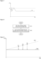
- FIG. 7 is a graph further describing FIG. 6 .
- the controller 410 may activate the substance detector 451 that detects the presence of a first aerosol generating substance.
- the controller 410 may block power supplied to the first heater 430 and the second heater 440 and supply power to the substance detector 451, in a standby mode.
- the standby mode may refer to a mode in which only a minimum amount of power is consumed to detect insertion of the first aerosol generating substance.
- the standby mode refers to any mode in which power supplied to remaining components other than components for detecting insertion of the first aerosol generating substance (e.g., a substance detector, etc.) is blocked before the first aerosol generating substance is inserted, and the standby mode according to one or more embodiments is not limited thereto.
- the standby mode may be similar to a mode like a power saving mode, a sleep mode, etc.
- the controller 410 may periodically collect inductance output values of the substance detector 451 after the substance detector 451 is activated.
- a period for collecting inductance output values may be appropriately set based on power consumption, an amount of change in inductance, etc.
- the controller 410 may collect inductance output values of the substance detector 451 at the interval of 0.5 ms, but one or more embodiments are not limited thereto.
- the controller 410 may collect inductance output values of the substance detector 451 in real time.
- the controller 410 may calculate an amount of change in inductance based on inductance output values.
- the first aerosol generating substance includes an electromagnetic inductor
- the inductance of a coil included in the substance detector 451 may be increased.
- FIG. 7 is a diagram showing an amount of change in inductance over time.
- the x-axis represents time
- the y-axis represents inductance output values of the substance detector 451
- a first graph 710 represents a change in inductance due to an insertion of the first aerosol generating substance.
- the substance detector 451 may output an inductance value to the controller 410 as a detection signal.
- the controller 410 may calculate an inductance increase ⁇ L1.
- the controller 410 may compare an amount of change in inductance with an upper-limit threshold value.
- the upper-limit threshold value may be set in consideration of self-inductance of the substance detector 451 and a mutual inductance between the substance detector 451 and the first aerosol generating substance.
- the upper-limit threshold value may be, but is not limited to, +0.32 mH.
- the controller 410 may determine that the first aerosol generating substance is inserted into the cavity 15 when the amount of change in inductance is equal to or greater than the upper-limit threshold value.
- the controller 410 may determine that the first aerosol generating substance is inserted into the cavity 15 since the inductance increase ⁇ L1 is equal to or greater than an upper-limit threshold value th1.
- the controller 410 may determine that the first aerosol generating substance is not inserted into the cavity 15 and maintain the standby mode. In other words, the controller 410 may block power supplied to the first heater 430 and the second heater 440, but continue to supply power to the substance detector 451. As such, the controller 410 may periodically collect inductance output values of the substance detector 451 while power is being supplied to the substance detector 451.
- the controller 410 may output a trigger signal for heating the first aerosol generating substance.
- the trigger signal may be a signal modulated through a PWM method.
- the controller 410 may output the trigger signal to the battery 420, and the battery 420 may supply power to the first heater 430 based on the trigger signal.
- pre-heating of the first heater 430 may be initiated by the trigger signal. Since the first heater 430 is automatically preheated in response to the insertion of the first aerosol generating substance even without a user input, thereby improving the user convenience.
- pre-heating of the second heater 440 may not be heated simultaneously as the first aerosol generating substance is inserted an detected.
- the reason for this is that the first heater 430 heats a solid substance, but the second heater 440 heats a liquid composition absorbed by a wick, which may reach a target pre-heating temperature more easily.
- the controller 410 may calculate a pre-heating start time for the second heater 440 based on the pre-heating time for the first heater 430 after the pre-heating of the first heater 430 is started. For example, when a pre-heating time for the first heater 430 is 30 seconds, the controller 410 may start pre-heating the second heater 440 from 27 seconds, that is, 3 seconds before the completion of the pre-heating of the first heater 430.
- the method of pre-heating the first heater 430 and the second heater 440 will be described below in more detail with reference to FIG. 8 .
- the output unit 460 may visually or audibly output an insertion state of the aerosol generating substance.
- the output unit 460 may further include a display and a speaker.
- the output unit 460 may display a screen image of detection of the first aerosol generating substance through the display and the speaker and may display whether entered a pre-heating mode.
- FIG. 8 is a flowchart of a method of heating a heater according to a pre-heating period and a smoking period.
- the controller 410 may pre-heat the first heater 430 during a pre-set pre-heating time.
- the controller 410 may output a trigger signal to the battery 420 for heating the first aerosol generating substance.
- the battery 420 may supply power to the first heater 430 based on the trigger signal. In other words, pre-heating of the first heater 430 may be initiated by the trigger signal.
- the controller 410 may heat the first heater 430 during the pre-set pre-heating time.
- the pre-heating time may be, but is not limited to, 30 seconds.
- the controller 410 may pre-heat the first heater 430 during a pre-set pre-heating time, thereby increasing the temperature of the first heater 430 to a vaporization temperature at which the first aerosol is generated. Therefore, the aerosol generating device according to one or more embodiments may provide a user with a rich flavor as soon as a smoking period is started.
- the controller 410 may calculate a pre-heating start timing for the second heater 440 based on the pre-heating time of the first heater 430.
- the controller 410 may start pre-heating the second heater 440 at a first time point before the pre-heating of the first heater 430 is completed. For example, when a pre-heating time for the first heater 430 is 30 seconds, the controller 410 may start pre-heating the second heater 440 from 27 seconds, that is, 3 seconds before the completion of the pre-heating of the first heater 430.
- the reason that the controller 410 does not control the second heater 440 to heat simultaneously as the controller 410 enters a pre-heating period is that, the first heater 430 heats a solid substance like a cigarette, but the second heater 440 heats a liquid composition absorbed by a wick, which may reach a target pre-heating temperature more easily.
- the controller 410 may control the power supplied to the second heater 440 for a first time period after the pre-heating of the second heater 440 is started at the first time point, such that the temperature of the second heater 440 exceeds a vaporization temperature at which the second aerosol is generated at a second time point, which is a time point after the first time period from the first time point.
- the controller 410 may control power supplied to the second heater 440 during a second time period from the second time point, such that the temperature of the second heater 440 at a time point at which the pre-heating of the second heater 440 is completed becomes a temperature that is lower than, and close to, the vaporization temperature for generating the second aerosol.
- the reason for pre-heating the temperature of the second heater 440 to a temperature that is lower than, and close to, the vaporization temperature for generating the second aerosol is to prevent the second aerosol generating substance, which is installed to increase the amount of smoke, from generating the second aerosol regardless of a puff of a user and to quickly heat the second aerosol generating substance in response to a puff of the user.
- the controller 410 may not supply additional power to the second heater 440 during the second time period from the second time point even when a puff of a user is detected. The reason thereof is to prevent coil carbonization due to overheating of the second heater 440.
- the controller 410 may heat the first heater 430 during a pre-set smoking time after the pre-heating time.
- the smoking time may be, but is not limited to, 4 minutes.
- the controller 410 may maintain the temperature of the first heater 430 above the temperature at which the first aerosol is generated and may heat the second heater 440 in response to a puff of a user.
- the controller 410 may control the temperature of the first heater 430 to maintain a first pre-heating temperature during the smoking period.
- the controller 410 may control the temperature of the first heater 430 through a proportional integral difference (PID) control method, but one or more embodiments are not limited thereto.
- PID proportional integral difference
- the controller 410 may increase the temperature of the second heater 440.
- the control unit 410 may not re-heat the second heater 440 even when the puff detector 453 detects successive puffs of the user during a pre-set rest period.
- the pre-set rest period may be 1 second. The reason thereof is to prevent coil carbonization due to overheating of the second heater 440.
- a liquid viscosity immediately before the smoking period may be reduced to a viscosity in which vaporization may easily occur. Therefore, an amount of smoke at the beginning of the smoking period may be significantly increased by increasing the transfer speed of a liquid composition to a wick. Also, user satisfaction may be improved due to the increase in the amount of smoke at the beginning of the smoking period.
- the inductance output value of the substance detector 451 may increase. Therefore, an error may occur when the presence of the first aerosol generating substance is determined based on the same criterion without the correction of the inductance output value.
- FIG. 9 is a diagram showing a change in an inductance output value according to an increase in the temperature of a heater.
- the inductance output value of the substance detector 451 may increase as the temperature of the first heater 430 and/or the second heater 440 increases.
- FIG. 9 shows an example of a change in an inductance output value according to a temperature change of the first heater 430.
- the x-axis represents the temperature of the first heater 430
- the y-axis represents the inductance output value of the substance detector 451.
- a second graph 910 shows the change in an actual inductance output values according to the temperature increase of the first heater 430
- a third graph 920 shows an ideal inductance output value according to the temperature increase of the first heater 430.
- FIG. 9 only shows that the second graph 910 linearly varies according to the temperature of the first heater 430.
- the second graph 910 may vary non-linearly according to the temperature change of the first heater 430.
- FIG. 10 is a flowchart for describing a method of detecting separation of an aerosol generating substance and a method of operating a heater and an output unit when an aerosol generating substance is separated
- FIG. 11 is a graph further describing FIG. 10 .
- the controller 410 may periodically collect inductance output values using the substance detector 451.
- a period for collecting inductance output values may be appropriately set based on power consumption, an amount of change in inductance, etc.
- the controller 410 may collect inductance output values of the substance detector 451 at the interval of 0.5 ms, but one or more embodiments are not limited thereto.
- the controller 410 may correct the inductance output value of the substance detector 451.
- the controller 410 may decrease the inductance output value of the substance detector 451 in response to an increase in the temperature of the first heater 430.
- the controller 410 may derive a first relational expression between the temperature of the first heater 430 and the inductance output value based on the inductance output values collected in operation S1010. For example, the controller 410 may estimate the first relational expression between the temperature of the first heater 430 and an inductance output value by using a method of least squares. The first relational expression between the temperature of the first heater 430 and the inductance output value may correspond to the second graph 910 of FIG. 9 . In FIG. 9 , the controller 410 may derive the second graph 910 based on three collected samples p1, p2, and p3.
- the memory 480 may store an ideal inductance output value according to the temperature increase of the first heater 430.
- the memory 480 may store a second relational expression between the temperature of the first heater 430 and the ideal inductance output value.
- the second relational expression between the temperature of the first heater 430 and the ideal inductance output value may correspond to the third graph 920 of FIG. 9 .
- the controller 410 may calculate a corrected value of a corresponding temperature based on the first relational expression and the second relational expression and subtract the corrected value from an actually measured inductance output value. Therefore, the second graph 910 of FIG. 9 may be corrected to be identical to the third graph 920.
- the controller 410 may calculate an amount of change in inductance based on the corrected inductance output value.
- the first aerosol generating substance includes an electromagnetic inductor, when the first aerosol generating substance is separated from the cavity 15, the inductance of a coil included in the substance detector 451 may be decreased.
- FIG. 11 is a diagram showing an amount of change in inductance over time.
- the x-axis represents time
- the y-axis represents inductance output values of the substance detector 451
- a fourth graph 1120 represents a change in inductance due to a separation of the first aerosol generating substance from the aerosol generating device.
- the substance detector 451 may output an inductance output value to the controller 410 as a detection signal.
- the controller 410 may calculate an inductance decrease ⁇ L2.
- the controller 410 may compare an amount of change in inductance with a lower-limit threshold value.
- the lower-limit threshold value may be set in consideration of self-inductance of the substance detector 451 and a mutual inductance between the substance detector 451 and the first aerosol generating substance.
- the lower-limit threshold value may be, but is not limited to, -0.32 mH.
- the controller 410 may determine that the first aerosol generating substance is separated from the cavity 15 when the amount of change in the inductance of the substance detector 451 is less than or equal to the lower-limit threshold value.
- the controller 410 may determine that the first aerosol generating substance is separated from the cavity 15 since the inductance decrease ⁇ L2 is less than or equal to a lower-limit threshold value th2.
- the controller 410 may determine that the first aerosol generating substance is still inserted into the cavity 15, heat the first heater 430 and the second heater 440, and calculate a change in the inductance based on a corrected inductance output value.
- the absolute value of the lower-limit threshold value th2 of FIG. 11 may be the same as the absolute value of the upper-limit threshold value th1 of FIG. 7 .
- the absolute value of the lower-limit threshold value th2 is set to be equal to the absolute value of the upper-limit threshold value th1, insertion and separation of the first aerosol generating substance may be determined more accurately.
- the controller 410 may determine whether to stop heating the first aerosol generating substance based on the amount of change in inductance.
- the output unit 460 may visually or audibly output a separation state of the aerosol generating substance.
- the output unit 460 may further include a display and a speaker.
- the output unit 460 may display a screen image of separation of the first aerosol generating substance through the display and the speaker and may display whether entered a standby mode.
- FIG. 12 is a flowchart of a method of stopping heating of a heater when an aerosol generating substance is separated.
- the controller 410 may periodically collect inductance output values of the substance detector 451 during a pre-set separation time.
- the pre-set separation time may be 5 seconds, but is not limited thereto.
- the controller 410 may calculate an amount of change in inductance based on inductance output values.
- the controller 410 may use a corrected inductance output value to more accurately determine the separation of the first aerosol generating substance. In other words, the controller 410 may calculate an amount of change in inductance based on the corrected inductance output value.
- the controller 410 may compare an amount of change in inductance with an upper-limit threshold value.
- the upper-limit threshold value may be set in consideration of self-inductance of the substance detector 451 and a mutual inductance between the substance detector 451 and the first aerosol generating substance.
- the upper-limit threshold value may be, but is not limited to, +0.32 mH.
- the controller 410 may stop heating the first aerosol generating substance when the amount of change in inductance is less than the upper-limit threshold value.
- the upper-limit threshold value of FIG. 12 may be the same as the upper-limit threshold value of FIGS. 6 and 7 .
- the controller 410 may alternatively determine that the first aerosol generating substance is re-inserted when the amount of change in inductance is equal to or greater than the upper-limit threshold value.
- the controller 410 may maintain heating of the first aerosol generating substance.
- the aerosol generating device 1 does not immediately stop heating a heater and stops heating the heater after a second determination of separation of the aerosol generating substance.
- the aerosol generating device 1 does not stop heating a heater and stops heating the heater based on detection of re-insertion of the aerosol generating substance.
- the aerosol generating device 1 may not only prevent heating of a heater from being stopped against an intention of a user, but also provide a rich flavor to the user by maintaining the temperature of the heater constantly during a smoking period.
- At least one of the components, elements, modules or units may be embodied as various numbers of hardware, software and/or firmware structures that execute respective functions described above, according to an exemplary embodiment.
- at least one of these components may use a direct circuit structure, such as a memory, a processor, a logic circuit, a look-up table, etc. that may execute the respective functions through controls of one or more microprocessors or other control apparatuses.
- At least one of these components may be specifically embodied by a module, a program, or a part of code, which contains one or more executable instructions for performing specified logic functions, and executed by one or more microprocessors or other control apparatuses.
- at least one of these components may include or may be implemented by a processor such as a central processing unit (CPU) that performs the respective functions, a microprocessor, or the like. Two or more of these components may be combined into one single component which performs all operations or functions of the combined two or more components. Also, at least part of functions of at least one of these components may be performed by another of these components.
- a bus is not illustrated in the above block diagrams, communication between the components may be performed through the bus. Functional aspects of the above exemplary embodiments may be implemented in algorithms that execute on one or more processors.
- the components represented by a block or processing steps may employ any number of related art techniques for electronics configuration, signal processing and/or control, data processing and the like.
- the embodiments of the inventive concept may be written as computer programs and can be implemented in computers that execute the programs using a non-transitory computer readable recording medium.
- the structure of the data used in the above-described method may be recorded on a computer-readable recording medium through various means.
- the computer readable recording medium include magnetic storage media (e.g., ROM, RAM, USB drives, floppy disks, hard disks, etc.), optical recording media (e.g., CD-ROMs, or DVDs), etc.
Landscapes
- Control Of Resistance Heating (AREA)
- Disinfection, Sterilisation Or Deodorisation Of Air (AREA)
- Sampling And Sample Adjustment (AREA)
- Investigating Or Analyzing Materials By The Use Of Fluid Adsorption Or Reactions (AREA)
- Other Investigation Or Analysis Of Materials By Electrical Means (AREA)
Abstract
Description
- The disclosure relates to an aerosol generating device and an operation method thereof, and more particularly, to an aerosol generating device capable of automatically heating a heater by recognizing an aerosol generating substance, and an operation method thereof.
- Recently, there is a growing demand for alternative methods of resolving problems of common cigarettes. For example, there is an increasing demand for a method of generating aerosols by heating an aerosol generating material in cigarettes or liquid storages rather than by burning cigarettes.
- However, in a conventional aerosol generating device, an additional input operation by a user is required to heat a heater after a cigarette is inserted, thereby causing inconvenience to the user and a delay until a first puff.
- One or more embodiments include an aerosol generating device capable of recognizing insertion of a cigarette and automatically heating a heater and an operation method thereof.
- One or more embodiments include an aerosol generating device capable of recognizing separation of a cigarette from the aerosol generating device and automatically stopping heating of a heater and an operation method thereof.
- The technical problems of the present disclosure are not limited to the above-description, and other technical problems may be solved from the embodiments described hereinafter.
- According to one or more embodiments, an operation method of an aerosol generating device, the method includes detecting whether an aerosol generating substance is inserted into a cavity based on an amount of change in inductance; heating the aerosol generating substance based on the aerosol generating substance being inserted into the cavity; detecting whether the aerosol generating substance is separated from the cavity based on the amount of change in the inductance while the aerosol generating substance is being heated; and, stopping the heating of the aerosol generating substance based on the amount of change in the inductance during a pre-set separation time when the aerosol generating substance is separated from the cavity.
- An aerosol generating device and an operation method thereof according to one or more embodiments may improve user convenience by automatically heating a heater without an additional user input after a cigarette is recognized.
- Also, the aerosol generating device and the operation method thereof may reduce a delay until a first puff of a user by automatically heating a heater after a cigarette is recognized.
- Also, the aerosol generating device and the operation method thereof automatically stop heating a heater by recognizing separation of a cigarette, thereby preventing overheating of the aerosol generating device and reducing power consumption.
- The advantages and effects according to the above-described embodiments are not limited thereto, and may include other advantages and effects that may be understood by one of ordinary skill in the art from the present disclosure.
-
-
FIGS. 1 and 2 are diagrams showing examples in which a cigarette is inserted into an aerosol generating device. -
FIG. 3 is a diagram showing an example of the cigarette shown inFIGS. 1 and 2 . -
FIG. 4 is a block diagram of an aerosol generating device according to one or more embodiments. -
FIG. 5 is a flowchart for describing a method of operation of a heater based on whether an aerosol generating substance is inserted and separated, according to one or more embodiments. -
FIG. 6 is a flowchart for describing a method of detecting an insertion of an aerosol generating substance and corresponding operations of a heater and an output unit when an aerosol generating substance is inserted. -
FIG. 7 is a graph further describingFIG. 6 . -
FIG. 8 is a flowchart of a method of heating a heater according to a pre-heating period and a smoking period. -
FIG. 9 is a graph showing a change in an inductance output value according to an increase in temperature of a heater. -
FIG. 10 is a flowchart for describing a method of detecting a separation of an aerosol generating substance and corresponding operations of a heater and an output unit when an aerosol generating substance is separated. -
FIG. 11 is a graph further describingFIG. 10 . -
FIG. 12 is a flowchart of a method of stopping heating of a heater when an aerosol generating substance is separated. - According to one or more embodiments, an operation method of an aerosol generating device, the method includes detecting whether an aerosol generating substance is inserted into a cavity based on an amount of change in inductance; heating the aerosol generating substance based on the aerosol generating substance being inserted into the cavity; detecting whether the aerosol generating substance is separated from the cavity based on the amount of change in the inductance while the aerosol generating substance is being heated; and based on determining that the aerosol generating substance is separated from the cavity, stopping the heating of the aerosol generating substance based on the amount of change in the inductance during a pre-set separation time.
- Also, the detecting of whether the aerosol generating substance is inserted into the cavity may include activating a substance detector configured to detect a presence of the aerosol generating substance; periodically collecting inductance output values of the substance detector after the substance detector is activated; calculating the amount of change in the inductance based on the inductance output values; and determining that the aerosol generating substance is inserted into the cavity based on the amount of change in the inductance being equal to or greater than a pre-set upper-limit threshold value.
- Also, the detecting of whether the aerosol generating substance is inserted into the cavity may further include, outputting a trigger signal for heating the aerosol generating substance based on determining that the aerosol generating substance is inserted into the cavity.
- Also, the detecting of whether the aerosol generating substance is inserted into the cavity may further include visually or audibly outputting an insertion state of the aerosol generating substance.
- Also, the heating of the aerosol generating substance may include pre-heating a heater for heating the aerosol generating substance during a pre-set pre-heating time; and heating the heater during a pre-set smoking time after the pre-set pre-heating time.
- Also, the pre-heating of the heater may include initiating pre-heating of the heater based on a trigger signal generated by an insertion of the aerosol generating substance; and increasing a temperature of the heater to a vaporization temperature at which aerosol is generated.
- Also, in the heating of the heater, the temperature of the heater may be maintained equal to or above the vaporization temperature during the smoking time.
- Also, the detecting of whether the aerosol generating substance is separated from the cavity may include correcting an inductance output value of a substance detector configured to detect a presence of the aerosol generating substance; calculating the amount of change in the inductance based on a corrected inductance output value; and determining that the aerosol generating substance is separated from the cavity based on the amount of change in the inductance being less than or equal to a pre-set lower-limit threshold value.
- Also, the correcting of the inductance output value includes decreasing the inductance output value of the substance detector in response to an increase in a temperature of a heater configured to heat the aerosol generating substance.
- Also, the detecting of whether the aerosol generating substance is separated from the cavity may further include visually or audibly outputting a separation state of the aerosol generating substance.
- Also, the stopping of the heating of the aerosol generating substance may include periodically collecting inductance output values of the substance detector during the pre-set separation time; calculating the amount of change in the inductance based on the inductance output values; and, stopping heating of the aerosol generating substance based on the amount of change in the inductance being less than a pre-set upper-limit threshold value.
- According to one or more embodiments, an aerosol generating device includes a cavity configured to receive an aerosol generating substance; a heater configured to heat the aerosol generating substance in the cavity; a substance detector configured to measure an inductance that varies according to an insertion and a separation of the aerosol generating substance; a battery configured to supply power to the heater and the substance detector; and a controller configured to determine the insertion and the separation of the aerosol generating substance based on an amount of change in the inductance and control the heater to heat the aerosol generating substance based on a result of the determination.
- Also, the controller may be further configured to activate the substance detector while the power is not supplied to the heater, periodically collect inductance output values of the substance detector, calculate the amount of change in the inductance based on the inductance output values, and determine that the aerosol generating substance is inserted into the cavity based on the amount of change in the inductance being equal to or greater than a pre-set upper-limit threshold value.
- Also, the controller may be further configured to output a trigger signal for heating the aerosol generating substance based on determining that the aerosol generating substance is inserted into the cavity.
- Also, a pre-heating of the heater may be initiated by the trigger signal, and the controller may be further configured to increase a temperature of the heater to a vaporization temperature at which aerosol is generated by pre-heating the heater during a pre-set pre-heating time.
- Also, the controller may maintain the temperature of the heater equal to or above the vaporization temperature during a pre-set smoking time after the pre-heating time.
- Also, the controller may be further configured to correct the inductance output value of the substance detector while the heater is being heated, calculate the amount of change in the inductance based on the corrected inductance output value, and determine that the aerosol generating substance is separated from the cavity based on the amount of change in the inductance being less than or equal to a pre-set lower-limit threshold value.
- Also, the controller may be further configured to correct the inductance output value by decreasing the inductance output value of the substance detector in response to an increase in the temperature of the heater.
- Also, the controller may be further configured to, periodically collect the inductance output values of the substance detector during a pre-set separation time based on determining that the aerosol generating substance is separated from the cavity, calculate the amount of change in the inductance based on the inductance output values, and, stop heating of the aerosol generating substance based on the amount of change in the inductance being less than a pre-set upper-limit threshold value.
- Also, the aerosol generating device may further include an output unit configured to visually or audibly output an insertion state and a separation state of the aerosol generating substance.
- As used herein, expressions such as "at least one of," when preceding a list of elements, modify the entire list of elements and do not modify the individual elements of the list. For example, the expression, "at least one of a, b, and c," should be understood as including only a, only b, only c, both a and b, both a and c, both b and c, or all of a, b, and c.
- It will be understood that when an element or layer is referred to as being "over," "above," "on," "connected to" or "coupled to" another element or layer, it can be directly over, above, on, connected or coupled to the other element or layer or intervening elements or layers may be present. In contrast, when an element is referred to as being "directly over," "directly above," "directly on," "directly connected to" or "directly coupled to" another element or layer, there are no intervening elements or layers present. Like numerals refer to like elements throughout.
- With respect to the terms in the various embodiments of the present disclosure, the general terms which are currently and widely used are selected in consideration of functions of structural elements in the various embodiments of the present disclosure. However, meanings of the terms may be changed according to intentions of one of ordinary skill in the art, a judicial precedent, an emergence of a new technology, and the like. In addition, in certain cases, there is also a term arbitrarily selected, in which case the meaning will be described in detail in the description of one or more embodiments. Therefore, the terms used in one or more embodiments should be defined based on the meanings of the terms and the context of the disclosure.
- In addition, unless explicitly indicated otherwise, the word "comprise" and variations such as "comprises" or "comprising" will be understood to imply the inclusion of stated elements but not the exclusion of any other elements. In addition, the terms "-er", "-or", and "module" may mean units for processing at least one function and operation and can be implemented by hardware components or software components and/or a combinations thereof.
- In the disclosure, "puff" may refer to an inhalation of certain aerosol by a user, and the inhalation may refer to an act of breathing in by a user through the user's mouth, nasal cavity, or lung.
- In the disclosure, a pre-heating period refers to a period for increasing respective temperatures of a first heater and a second heater, and a smoking period may refer to a period for maintaining the temperature of the first heater and a period during which a user inhales aerosol. Hereinafter, a pre-heating period and a smoking period may have the same meaning as a pre-heating time and a smoking time, respectively.
- Hereinafter, the present disclosure will be described in more detail with reference to the accompanying drawings, in which exemplary embodiments of the present disclosure are described such that one of ordinary skill in the art may understand and practice the one or more embodiments of the present disclosure. The inventive concept may, however, be embodied in many different forms and should not be construed as being limited to the embodiments set forth herein.
- Hereinafter, one or more embodiments of the inventive concept will be described in detail with reference to the drawings.
-
FIGS. 1 and 2 are diagrams showing examples in which a cigarette is inserted into an aerosol generating device. - Referring to
FIG. 1 and 2 , theaerosol generating device 1 may include abattery 11, acontroller 12, aheater 13 andvaporizer 14. Also, thecigarette 2 may be inserted into an inner space of theaerosol generating device 1. -
FIGS. 1 and 2 illustrate certain components of theaerosol generating device 1. It will be understood by one of ordinary skill in the art related to the present embodiment that other components may be further included in theaerosol generating device 1, in addition to the components illustrated inFIGS. 1 and 2 . -
FIG. 1 illustrates that thebattery 11, thecontroller 12, theheater 13, andvaporizer 14 are arranged in series. In addition,FIG. 2 illustrates that thevaporizer 14 and theheater 13 are arranged in parallel. However, the internal structure of theaerosol generating device 1 is not limited to the structures illustrated inFIGS. 1 and 2 . In other words, according to the design of theaerosol generating device 1, thebattery 11, thecontroller 12, theheater 13, and thevaporizer 14 may be arranged differently. - When the
cigarette 2 is inserted into acavity 15 of theaerosol generating device 1, theaerosol generating device 1 may operate theheater 13 and/or thevaporizer 14 to generate an aerosol. The aerosol generated by theheater 13 and/or thevaporizer 14 is delivered to a user by passing through thecigarette 2. - The
battery 11 may supply power to be used for theaerosol generating device 1 to operate. For example, thebattery 11 may supply power to heat theheater 13 or thevaporizer 14, and may supply power for operating thecontroller 12. Also, thebattery 11 may supply power for operations of a display, a sensor, a motor, etc. included in theaerosol generating device 1. - The
controller 12 may control overall operations of theaerosol generating device 1. In detail, thecontroller 12 may control not only operations of thebattery 11, theheater 13, and thevaporizer 14, but also operations of other components included in theaerosol generating device 1. Also, thecontroller 12 may check a state of each of the components of theaerosol generating device 1 to determine whether or not theaerosol generating device 1 is in an operable state. - The
controller 12 may include at least one processor. A processor can be implemented as an array of a plurality of logic gates or can be implemented as a combination of a microprocessor and a memory in which a program executable by the microprocessor is stored. It will be understood by one of ordinary skill in the art that one or more processors can be implemented in other forms of hardware. - The
heater 13 may be heated by the power supplied from thebattery 11. For example, when thecigarette 2 is inserted into theaerosol generating device 1, theheater 13 may be located outside thecigarette 2. Thus, theheated heater 13 may increase a temperature of an aerosol generating material in thecigarette 2. - The
heater 13 may include an electro-resistive heater. For example, theheater 13 may include an electrically conductive track, and theheater 13 may be heated when currents flow through the electrically conductive track. However, theheater 13 is not limited to the example described above and may include any heaters which may be heated to a desired temperature. Here, the desired temperature may be pre-set in theaerosol generating device 1 or may be set as a temperature desired by a user. - As another example, the
heater 13 may include an induction heater. In detail, theheater 13 may include an electrically conductive coil for heating a cigarette in an induction heating method, and the cigarette may include a susceptor which may be heated by the induction heater. - For example, the
heater 13 may include a tube-type heating element, a plate-type heating element, a needle-type heating element, or a rod-type heating element, and may heat the inside or the outside of thecigarette 2, according to the shape of the heating element. - Also, the
aerosol generating device 1 may include a plurality ofheaters 13. Here, the plurality ofheaters 13 may be inserted into thecigarette 2 or may be arranged outside thecigarette 2. Also, some of the plurality ofheaters 13 may be inserted into thecigarette 2 and the others may be arranged outside thecigarette 2. In addition, the shape of theheater 13 is not limited to the shapes illustrated inFIGS. 1 through 3 and may include various shapes. - The
vaporizer 14 may generate an aerosol by heating a liquid composition and the generated aerosol may pass through thecigarette 2 to be delivered to a user. In other words, the aerosol generated via thevaporizer 14 may move along an air flow passage of theaerosol generating device 1 and the air flow passage may be configured such that the aerosol generated via thevaporizer 14 passes through thecigarette 2 and delivered to the user. - For example, the
vaporizer 14 may include a liquid storage, a liquid delivery element, and a heating element, but it is not limited thereto. For example, the liquid storage, the liquid delivery element, and the heating element may be included in theaerosol generating device 1 as independent modules. - The liquid storage may store a liquid composition. For example, the liquid composition may be a liquid including a tobacco-containing material having a volatile tobacco flavor component, or a liquid including a non-tobacco material. The liquid storage may be formed to be attached to/detached from the
vaporizer 14 or may be formed integrally with thevaporizer 14. - For example, the liquid composition may include water, a solvent, ethanol, plant extract, spices, flavors, or a vitamin mixture. The spices may include menthol, peppermint, spearmint oil, and various fruit-flavored ingredients, but are not limited thereto. The flavors may include ingredients capable of providing various flavors or tastes to a user. Vitamin mixtures may be a mixture of at least one of vitamin A, vitamin B, vitamin C, and vitamin E, but are not limited thereto. Also, the liquid composition may include an aerosol forming substance, such as glycerin and propylene glycol.
- The liquid delivery element may deliver the liquid composition of the liquid storage to the heating element. For example, the liquid delivery element may be a wick such as cotton fiber, ceramic fiber, glass fiber, or porous ceramic, but is not limited thereto.
- The heating element is an element for heating the liquid composition delivered by the liquid delivery element. For example, the heating element may be a metal heating wire, a metal hot plate, a ceramic heater, or the like, but is not limited thereto. In addition, the heating element may include a conductive filament such as nichrome wire and may be positioned as being wound around the liquid delivery element. The heating element may be heated by a current supply and may transfer heat to the liquid composition in contact with the heating element, thereby heating the liquid composition. As a result, aerosol may be generated.
- In addition, the
vaporizer 14 may be referred to as a cartomizer or an atomizer, but it is not limited thereto. - The
aerosol generating device 1 may further include other components in addition to thebattery 11, thecontroller 12, theheater 13, and thevaporizer 14. For example, theaerosol generating device 1 may include a display configured to output visual information and/or a motor for outputting haptic information. Also, theaerosol generating device 1 may include at least one sensor (e.g., a puff detecting sensor, a temperature detecting sensor, a cigarette insertion detecting sensor, etc.). Also, theaerosol generating device 1 may be formed as a structure where, even when thecigarette 2 is inserted into theaerosol generating device 1, external air may be introduced or internal air may be discharged. - Although not illustrated in
FIGS. 1 and 2 , theaerosol generating device 1 and an additional cradle may form together a system. For example, the cradle may be used to charge thebattery 11 of theaerosol generating device 1. Alternatively, theheater 13 may be heated when the cradle and theaerosol generating device 1 are coupled to each other. - The
cigarette 2 may be a general combustive cigarette. For example, thecigarette 2 may be divided into a first portion including an aerosol generating material and a second portion including a filter, etc. Alternatively, the second portion of thecigarette 2 may also include an aerosol generating material. For example, an aerosol generating material made in the form of granules or capsules may be inserted into the second portion. - The entire first portion may be inserted into the
aerosol generating device 1, and the second portion may be exposed to the outside. Alternatively, only a portion of the first portion may be inserted into theaerosol generating device 1, or the entire first portion and a portion of the second portion may be inserted into theaerosol generating device 1. The user may puff aerosol while holding the second portion by the mouth of the user. In this case, the aerosol is generated by the external air passing through the first portion, and the generated aerosol passes through the second portion and is delivered to the user's mouth. - For example, the external air may flow into at least one air passage formed in the
aerosol generating device 1. For example, the opening and closing and/or a size of the air passage formed in theaerosol generating device 1 may be adjusted by the user. Accordingly, the amount of smoke and a smoking impression may be adjusted by the user. As another example, the external air may flow into thecigarette 2 through at least one hole formed in a surface of thecigarette 2. Hereinafter, an example of thecigarette 2 will be described with reference toFIG. 3 . -
FIG. 3 illustrates an example of a cigarette shown inFIG. 1 and 2 . - The
cigarette 3 ofFIG. 3 may correspond to thecigarette 2 ofFIGS. 1 and 2 . - Referring to
FIG. 3 , thecigarette 3 may include atobacco rod 31 and afilter rod 32. Thefirst portion 31 described above with reference toFIGS. 1 and 2 may include the tobacco rod, and the second portion may include thefilter rod 32. - According to embodiments, the
cigarette 3 may include a front-end plug 33. The front-end plug 33 may be located on a side of thetobacco rod 31, the side opposite from thefilter rod 32. The front-end plug 33 may prevent thetobacco rod 31 from being detached outward and prevent a liquefied aerosol from flowing into theaerosol generating device 1 from thetobacco rod 31 during smoking. - The
tobacco rod 31 may include an aerosol generating material. For example, the aerosol generating material may include at least one of glycerin, propylene glycol, ethylene glycol, dipropylene glycol, diethylene glycol, triethylene glycol, tetraethylene glycol, and oleyl alcohol, but it is not limited thereto. Also, thetobacco rod 31 may include other additives, such as flavors, a wetting agent, and/or organic acid. Also, thetobacco rod 31 may include a flavored liquid, such as menthol or a moisturizer, which may be injected into thetobacco rod 31. - The
tobacco rod 31 may be manufactured in various forms. For example, thetobacco rod 31 may be formed as a sheet or a strand. Also, thetobacco rod 31 may be formed as a pipe tobacco, which is formed of tiny bits cut from a tobacco sheet. Also, thetobacco rod 31 may be surrounded by a heat conductive material. For example, the heat-conducting material may be, but is not limited to, a metal foil such as aluminum foil. For example, the heat conductive material surrounding thetobacco rod 31 may uniformly distribute heat transmitted to thetobacco rod 31, and thus, the heat conductivity applied to the tobacco rod may be increased and taste of the tobacco may be improved. Also, the heat conductive material surrounding thetobacco rod 31 may function as a susceptor heated by the induction heater. Here, although not illustrated in the drawings, thetobacco rod 31 may further include an additional susceptor, in addition to the heat conductive material surrounding thetobacco rod 31. - The
filter rod 32 may include a first segment and a second segment. Thefilter rod 32 may include a cellulose acetate filter. Also, the shape of thefilter rod 32 are not limited. For example, thefilter rod 32 may include a cylinder-type rod or a tube-type rod having a hollow inside. Also, thefilter rod 32 may include a recess-type rod. When thefilter rod 32 includes a plurality of segments, at least one of the plurality of segments may have a different shape. - Also, the
filter rod 32 may include at least onecapsule 34. Here, thecapsule 34 may generate a flavor or an aerosol. For example, thecapsule 34 may have be formed such that a liquid containing a flavoring material is wrapped with a film. For example, thecapsule 34 may have a spherical or cylindrical shape, but is not limited thereto. - The length of the front-
end plug 33 may be about 7 mm, the length of thetobacco rod 31 may be about 15 mm, the length of thefirst segment 321 may be about 12 mm, and the length of thesecond segment 322 may be about 14 mm, however, the length of each component described above is not limited thereto. - The
cigarette 3 may be packaged by at least onewrapper 35. Thewrapper 35 may have at least one hole through which external air may be introduced or internal air may be discharged. For example, the front-end plug 33 may be packaged by afirst wrapper 351, and thetobacco rod 31 may be packaged by asecond wrapper 352, and thefirst segment 321 may be packaged by athird wrapper 353, and thesecond segment 322 may be packaged by afourth wrapper 354. Also, theentire cigarette 3 may be packaged by afifth wrapper 355. - Also, the
fifth wrapper 355 may have at least onehole 36. For example, thehole 36 may be formed in an area surrounding thetobacco rod 31, but is not limited thereto. Thehole 36 may serve to transfer heat formed by theheater 13 shown inFig. 1 and Fig. 2 to the inside of thetobacco rod 31. - On the other hand, the
cigarette 3 may further include an electromagnetic inductor. The electromagnetic inductor may change the inductance of asubstance detector 451 inFIG. 4 described below. The electromagnetic inductor may include a conductor capable of inducing an eddy current and a magnetic material capable of inducing a magnetic flux change. For example, the electromagnetic inductor may include a metallic material, a magnetic ink, a magnetic tape, etc. For example, the electromagnetic inductor may be an aluminum foil. Also, the electromagnetic inductor may include materials that change the inductance of thesubstance detector 451 without limitation. - In an embodiment, at least one of the first to
fifth wrappers 351 to 355 may include an electromagnetic inductor material. - In another embodiment, the electromagnetic inductor may surround at least one wrapper among the first to
fifth wrappers 351 to 355 along the circumference of thecigarette 3 while one side surface of the electromagnetic inductor facing the inner surface of the at least one wrapper. - The position at which the electromagnetic inductor is provided within the
cigarette 3 may vary. - In an embodiment, the electromagnetic inductor may be provided in a region corresponding to the front-
end plug 33. Here, since thecigarette 3 is inserted into theaerosol generating device 1 in a direction in which the front-end plug 33 faces theaerosol generating device 1, the electromagnetic inductor may be inserted into theaerosol generating device 1 as soon as the insertion of thecigarette 3 is started. Therefore, thesubstance detector 451 may detect that the insertion of thecigarette 3 is started at an early point by detecting the proximity of the electromagnetic inductor. - Also, when the
cigarette 3 is separated from the aerosol generating device, the front-end plug 33 is separated from theaerosol generating device 1 at the end, and thus thesubstance detector 451 may detect that thecigarette 3 is completely separated by detecting separation of the electromagnetic inductor. - In another embodiment, the electromagnetic inductor may be inside the
tobacco rod 31 or surround thetobacco rod 31 while being overlapped with thefifth wrapper 355. - In another embodiment, the electromagnetic inductor may be inside the
filter rod 32 or surround thefilter rod 32 while being overlapped with thefifth wrapper 355. - In another embodiment, the electromagnetic inductor may be provided between segments. Alternatively, the electromagnetic inductor may be provided at the bottom or the top of the
cigarette 3. -
FIG. 4 is a block diagram of an aerosol generating device according to one or more embodiments. - Referring to
FIG. 4 , theaerosol generating device 1 according to one or more embodiments may include acontroller 410, abattery 420, afirst heater 430, asecond heater 440, adetector 450, anoutput unit 460, aninput unit 470, and amemory 480. - Also, the
detector 450 may include asubstance detector 451 that detects an aerosol generating substance, apuff detector 453 that detects a puff of a user, and a temperature detector that detects temperatures of theheaters - The
controller 410 may collectively control thebattery 420, thefirst heater 430, thesecond heater 440, thedetector 450, theoutput unit 460, theinput unit 470, and thememory 480 included in theaerosol generating device 1. - The
battery 420 supplies power to thefirst heater 430 and thesecond heater 440, and the amount of power supplied to each of thefirst heater 430 and thesecond heater 440 may be adjusted by thecontroller 410. - The
first heater 430 may generate a first aerosol by heating a first aerosol generating substance. When a current is applied to thefirst heater 430, heat is generated by a specific resistance, and, when a first aerosol generating substance contacts (or combined with) the heatedfirst heater 430, aerosol may be generated. - The
first heater 430 may be a component corresponding to theheater 13 ofFIGS. 1 and 2 . Also, the first aerosol generating substance may be thecigarette 2 ofFIGS. 1 and 2 . The first aerosol generating substance may be a solid substrate including nicotine. - The
second heater 440 may generate a second aerosol by heating a second aerosol generating substance. Thesecond heater 440 may be a component corresponding to a heating element provided in thevaporizer 14 ofFIGS. 1 and 2 . Also, the second aerosol generating substance may be a liquid composition stored in the liquid storage ofFIGS. 1 and 2 . The second aerosol generating substance may be a liquid substance including an aerosol forming agent. - The
second heater 440 may generate a second aerosol by heating the second aerosol generating substance, and the generated second aerosol may pass through the first aerosol generating substance and be delivered to a user together with the first aerosol. - The
controller 410 may control power supplied to thefirst heater 430 and thesecond heater 440. Thecontroller 410 may adjust power supplied to thefirst heater 430 and thesecond heater 440 by controlling thebattery 420. - The
controller 410 may control power supplied to thefirst heater 430 and thesecond heater 440 through a pulse width modulation (PWM). To this end, thecontroller 410 may include a PWM module. - The
controller 410 may determine whether the first aerosol generating substance is inserted and extracted, and, based on a result of the determination, control power supplied to thefirst heater 430 and thesecond heater 440, thereby heating thefirst heater 430 and thesecond heater 440. - Specifically, the inductance of the
substance detector 451 may vary as the first aerosol generating substance is inserted and separated. For example, thesubstance detector 451 may include at least one inductance to digital converter (LDC). When there are a plurality of LDCs, the plurality of LDCs may detect the state of insertion and separation of the first aerosol generating substance at different positions. - When the first aerosol generating substance is the
cigarette 2 ofFIGS. 1 and 2 , thesubstance detector 451 may be provided in thecavity 15 to detect the presence of thecigarette 2. Here, thesubstance detector 451 may also be referred to as a cigarette detector. - The
controller 410 may determine whether the first aerosol generating substance is inserted or separated based on an amount of change in the inductance of thesubstance detector 451. Thecontroller 410 may determine that the first aerosol generating substance is inserted into thecavity 15 when the amount of change in the inductance of thesubstance detector 451 is equal to or greater than a pre-set upper-limit threshold value. Thecontroller 410 may determine that the first aerosol generating substance is separated from thecavity 15 when the amount of change in the inductance of thesubstance detector 451 is less than or equal to a pre-set lower-limit threshold value. - When it is determined that the first aerosol generating substance is inserted into the
cavity 15, thecontroller 410 may output a trigger signal for heating the first aerosol generating substance. The trigger signal may be a PWM type signal. Thecontroller 410 may start supplying power to thefirst heater 430 through the trigger signal. In other words, when it is determined that the first aerosol generating substance is inserted into thecavity 15, thecontroller 410 may start pre-heating thefirst heater 430. - Also, after the pre-heating of the
first heater 430 is started, thecontroller 410 may start pre-heating thesecond heater 440 at a first time point before the pre-heating of thefirst heater 430 is completed. For example, when a pre-heating time period for thefirst heater 430 is 30 seconds, thecontroller 410 may start pre-heating thesecond heater 440 from 27 seconds, that is, 3 seconds before the completion of the pre-heating of thefirst heater 430. - The
controller 410 may calculate a pre-heating start timing for thesecond heater 440 based on the pre-heating time of thefirst heater 430. Thecontroller 410 may start pre-heating thesecond heater 440 at a predetermined time point before the pre-heating of thefirst heater 430 is completed. The reason for thecontroller 410, as thecontroller 410 enters a pre-heating period, controlling thesecond heater 440 to not to be heated simultaneously with thefirst heater 430 is that, thefirst heater 430 heats a solid substance like a cigarette while thesecond heater 440 heats a liquid composition absorbed by a wick, which may reach a target pre-heating temperature more easily. - The
controller 410 may control power supplied to thefirst heater 430 during a pre-set pre-heating time, such that the temperature of thefirst heater 430 rises to a vaporization temperature at which the first aerosol is generated by a time point at which the pre-heating of thefirst heater 430 is completed. - Also, the
controller 410 may control the power supplied to thesecond heater 440 for a first time period after the pre-heating of thesecond heater 440 is started at the first time point, such that the temperature of thesecond heater 440 exceeds a vaporization temperature at which the second aerosol is generated at a second time point, which is a time point after the first time period from the first time point. - Also, the
controller 410 may control power supplied to thesecond heater 440 during a second time period from the second time point, such that the temperature of thesecond heater 440 at a time point at which the pre-heating of thesecond heater 440 is completed becomes a temperature that is lower than, or close to, the vaporization temperature for generating the second aerosol. - The reason for pre-heating the temperature of the
second heater 440 to a temperature that is lower than, or close to, the vaporization temperature for generating the second aerosol is to prevent the second aerosol generating substance, which is installed to increase the amount of smoke, from generating the second aerosol regardless of a puff of a user and to quickly heat the second aerosol generating substance in response to a puff of the user. - In addition, the
controller 410 may not supply additional power to thesecond heater 440 during the second time period from the second time point even when a puff of a user is detected. The reason thereof is to prevent coil carbonization due to overheating of thesecond heater 440. - The
controller 410 may control the temperatures of thefirst heater 430 and thesecond heater 440 based on a temperature profile stored in thememory 480 during a pre-set smoking time after the pre-heating time. - When the
first heater 430 and thesecond heater 440 are heated, thecontroller 410 may correct an inductance output value of thesubstance detector 451 according to an increase in the temperature of thefirst heater 430 and/or thesecond heater 440. Thecontroller 410 may decrease the inductance output value of thesubstance detector 451 in response to an increase in the temperature of any one of thefirst heater 430 and thesecond heater 440. - The
controller 410 may determine whether the first aerosol generating substance is separated based on the corrected inductance output value. - When it is determined that the first aerosol generating substance is separated from the
cavity 15 while thefirst heater 430 and thesecond heater 440 are being heated, thecontroller 410 may not immediately stop heating of thefirst heater 430 and thesecond heater 440 and continuously calculate the amount of change in the inductance of thesubstance detector 451. The reason for the continuous calculation is to detect a case in which the first aerosol generating substance is separated from thecavity 15 against the intention of a user. - The
controller 410 may determine whether the first aerosol generating substance is re-inserted based on the amount of change in the inductance of thesubstance detector 451 during a pre-set separation time. When the first aerosol generating substance is re-inserted within the pre-set separation time, thecontroller 410 may continuously heat thefirst heater 430 and thesecond heater 440. When the first aerosol generating substance is not re-inserted within the pre-set separation time, thecontroller 410 may stop heating thefirst heater 430 and thesecond heater 440. Therefore, theaerosol generating device 1 according to one or more embodiments may reduce unnecessary power consumption and prevent overheating of theaerosol generating device 1. - The
puff detector 453 may detect a puff of a user. To this end, thepuff detector 453 may include at least one pressure sensor. - When the pressure inside the
aerosol generating device 1 is less than or equal to a reference pressure, thepuff detector 453 may transmit a puff detection signal to thecontroller 410. Thecontroller 410 may heat thesecond heater 440 in response to receiving the puff detection signal. - The
temperature detector 455 may be provided in each of thefirst heater 430 and thesecond heater 440 and detect the temperatures of thefirst heater 430 and thesecond heater 440. To this end, thetemperature detector 455 may include a temperature sensor. For example, thetemperature detector 455 may detect changes in thermal resistances of thefirst heater 430 and thesecond heater 440. - The
temperature detector 455 may transmit a temperature detection signal to thecontroller 410. Thecontroller 410 may calculate the temperatures of thefirst heater 430 and thesecond heater 440 based on the temperature detection signal. Thecontroller 410 may calculate heating time points, heating periods, and power to be supplied to thefirst heater 430 and thesecond heater 440 based on the temperatures of thefirst heater 430 and thesecond heater 440. - The
output unit 460 may output visual information and/or tactile information related to theaerosol generating device 1. - The
input unit 470 may receive a user input. For example, theinput unit 470 may be provided in the form of a press-push button. - The
input unit 470 may receive ON/OFF commands for theaerosol generating device 1. When an operation command for theaerosol generating device 1 is received, theinput unit 470 may transmit a control signal corresponding to the operation command to thecontroller 410. - The
memory 480 may store information for the operation of theaerosol generating device 1. For example, thememory 480 may store a temperature profile for thecontroller 410 to appropriately control power supply to thefirst heater 430 and thesecond heater 440 to provide various flavors to a user of theaerosol generating device 1. The temperature profile may include information, such as pre-heating time points, pre-heating periods, and pre-heating temperatures for thefirst heater 430 and thesecond heater 440. -
FIG. 5 is a flowchart for describing a method of operating a heater according to whether an aerosol generating substance is inserted and separated, according to one or more embodiments. - Referring to
FIG. 5 , in operation S510, thecontroller 410 may determine whether a first aerosol generating substance is inserted into thecavity 15 based on the amount of change in the inductance of thesubstance detector 451. - The
controller 410 may determine whether the first aerosol generating substance is inserted into thecavity 15 based on an inductance output value output by thesubstance detector 451. Thecontroller 410 may determine that the first aerosol generating substance is inserted into thecavity 15 based on the amount of change in the inductance of thesubstance detector 451 being equal to or greater than a pre-set upper-limit threshold value. - In operation S520, when the first aerosol generating substance is inserted into the
cavity 15, thecontroller 410 may control one or more heaters to heat the first aerosol generating substance. - The
controller 410 may automatically heat thefirst heater 430 when the first aerosol generating substance is inserted into thecavity 15. In other words, thecontroller 410 may heat thefirst heater 430 without a user input when the first aerosol generating substance is inserted into thecavity 15. - In operation S530, the
controller 410 may detect whether the first aerosol generating substance is separated from thecavity 15 based on an amount of change in the inductance of thesubstance detector 451 while the first aerosol generating substance is being heated. - The inductance output value of the
substance detector 451 may be increased according to an increase in the temperature of thefirst heater 430 and/or thesecond heater 440. Therefore, in order to accurately detect separation of the first aerosol generating substance, it is necessary to correct the inductance output value of thesubstance detector 451. - The
controller 410 may decrease the inductance output value of thesubstance detector 451 in response to an increase in the temperature of any one of thefirst heater 430 and thesecond heater 440. - The
controller 410 may determine whether the first aerosol generating substance is separated based on the corrected inductance output value. Thecontroller 410 may determine that the first aerosol generating substance is separated from thecavity 15 based the amount of change in the corrected inductance of thesubstance detector 451 being less than or equal to a pre-set lower-limit threshold value. - In operation S540, when the first aerosol generating substance is separated from the
cavity 15, thecontroller 410 may stop heating the first aerosol generating substance based on an amount of change in the inductance of thesubstance detector 451 during a pre-set separation time. - The
controller 410 may determine whether the first aerosol generating substance is re-inserted based on the amount of change in the inductance of thesubstance detector 451 during the pre-set separation time. For example, the pre-set separation time may be set to 5 seconds, but the pre-set separation time is not limited thereto. - The
controller 410 may block power supply to thefirst heater 430 and thesecond heater 440 when the amount of change in the inductance of thesubstance detector 451 during the pre-set separation time is less than the pre-set upper-limit threshold value. In other words, when thecontroller 410 fails to detect re-insertion of the first aerosol generating substance during the pre-set separation time after the first aerosol generating substance is separated, thecontroller 410 may stop heating thefirst heater 430 and thesecond heater 440 without a user input. - When the amount of change in the inductance of the
substance detector 451 during the pre-set separation time is equal to or greater than the pre-set upper-limit threshold value, thecontroller 410 may determine that the first aerosol generating substance is inserted and continue supplying power to thefirst heater 430 and thesecond heater 440. -
FIG. 6 is a flowchart for describing a method of detecting an insertion of an aerosol generating substance and corresponding operations of a heater and an output unit when an aerosol generating substance is inserted, andFIG. 7 is a graph further describingFIG. 6 . - Referring to
FIG. 6 , in operation S610, thecontroller 410 may activate thesubstance detector 451 that detects the presence of a first aerosol generating substance. - The
controller 410 may block power supplied to thefirst heater 430 and thesecond heater 440 and supply power to thesubstance detector 451, in a standby mode. The standby mode may refer to a mode in which only a minimum amount of power is consumed to detect insertion of the first aerosol generating substance. The standby mode refers to any mode in which power supplied to remaining components other than components for detecting insertion of the first aerosol generating substance (e.g., a substance detector, etc.) is blocked before the first aerosol generating substance is inserted, and the standby mode according to one or more embodiments is not limited thereto. For example, the standby mode may be similar to a mode like a power saving mode, a sleep mode, etc. - In operation S620, the
controller 410 may periodically collect inductance output values of thesubstance detector 451 after thesubstance detector 451 is activated. - A period for collecting inductance output values may be appropriately set based on power consumption, an amount of change in inductance, etc. For example, the
controller 410 may collect inductance output values of thesubstance detector 451 at the interval of 0.5 ms, but one or more embodiments are not limited thereto. - According to an embodiment, the
controller 410 may collect inductance output values of thesubstance detector 451 in real time. - In operation S630, the
controller 410 may calculate an amount of change in inductance based on inductance output values. - Specifically, since the first aerosol generating substance includes an electromagnetic inductor, when the first aerosol generating substance is inserted into the
cavity 15, the inductance of a coil included in thesubstance detector 451 may be increased. -
FIG. 7 is a diagram showing an amount of change in inductance over time. InFIG. 7 , the x-axis represents time, the y-axis represents inductance output values of thesubstance detector 451, and afirst graph 710 represents a change in inductance due to an insertion of the first aerosol generating substance. - As shown in
FIG. 7 , it may be seen that, when the first aerosol generating substance is inserted into thecavity 15, the inductance output value increases. Thesubstance detector 451 may output an inductance value to thecontroller 410 as a detection signal. Thecontroller 410 may calculate an inductance increase ΔL1. - Referring back to
FIG. 6 , in operation S640, thecontroller 410 may compare an amount of change in inductance with an upper-limit threshold value. - The upper-limit threshold value may be set in consideration of self-inductance of the
substance detector 451 and a mutual inductance between thesubstance detector 451 and the first aerosol generating substance. For example, the upper-limit threshold value may be, but is not limited to, +0.32 mH. - In operation S650, the
controller 410 may determine that the first aerosol generating substance is inserted into thecavity 15 when the amount of change in inductance is equal to or greater than the upper-limit threshold value. - For example, in
FIG. 7 , thecontroller 410 may determine that the first aerosol generating substance is inserted into thecavity 15 since the inductance increase ΔL1 is equal to or greater than an upper-limit threshold value th1. - In another example, when the inductance increase ΔL1 is less than the upper-limit threshold value (th1), the
controller 410 may determine that the first aerosol generating substance is not inserted into thecavity 15 and maintain the standby mode. In other words, thecontroller 410 may block power supplied to thefirst heater 430 and thesecond heater 440, but continue to supply power to thesubstance detector 451. As such, thecontroller 410 may periodically collect inductance output values of thesubstance detector 451 while power is being supplied to thesubstance detector 451. - In operation S660, when it is determined that the first aerosol generating substance is inserted into the
cavity 15, thecontroller 410 may output a trigger signal for heating the first aerosol generating substance. - In an embodiment, the trigger signal may be a signal modulated through a PWM method. The
controller 410 may output the trigger signal to thebattery 420, and thebattery 420 may supply power to thefirst heater 430 based on the trigger signal. In other words, pre-heating of thefirst heater 430 may be initiated by the trigger signal. Since thefirst heater 430 is automatically preheated in response to the insertion of the first aerosol generating substance even without a user input, thereby improving the user convenience. - Further, pre-heating of the
second heater 440 may not be heated simultaneously as the first aerosol generating substance is inserted an detected. The reason for this is that thefirst heater 430 heats a solid substance, but thesecond heater 440 heats a liquid composition absorbed by a wick, which may reach a target pre-heating temperature more easily. - The
controller 410 may calculate a pre-heating start time for thesecond heater 440 based on the pre-heating time for thefirst heater 430 after the pre-heating of thefirst heater 430 is started. For example, when a pre-heating time for thefirst heater 430 is 30 seconds, thecontroller 410 may start pre-heating thesecond heater 440 from 27 seconds, that is, 3 seconds before the completion of the pre-heating of thefirst heater 430. The method of pre-heating thefirst heater 430 and thesecond heater 440 will be described below in more detail with reference toFIG. 8 . - In operation S670, the
output unit 460 may visually or audibly output an insertion state of the aerosol generating substance. - To this end, the
output unit 460 may further include a display and a speaker. Theoutput unit 460 may display a screen image of detection of the first aerosol generating substance through the display and the speaker and may display whether entered a pre-heating mode. -
FIG. 8 is a flowchart of a method of heating a heater according to a pre-heating period and a smoking period. - Referring to
FIG. 8 , in operation S810, thecontroller 410 may pre-heat thefirst heater 430 during a pre-set pre-heating time. - Specifically, when it is determined that a first aerosol generating substance is inserted into a cavity, the
controller 410 may output a trigger signal to thebattery 420 for heating the first aerosol generating substance. Thebattery 420 may supply power to thefirst heater 430 based on the trigger signal. In other words, pre-heating of thefirst heater 430 may be initiated by the trigger signal. - The
controller 410 may heat thefirst heater 430 during the pre-set pre-heating time. For example, the pre-heating time may be, but is not limited to, 30 seconds. - The
controller 410 may pre-heat thefirst heater 430 during a pre-set pre-heating time, thereby increasing the temperature of thefirst heater 430 to a vaporization temperature at which the first aerosol is generated. Therefore, the aerosol generating device according to one or more embodiments may provide a user with a rich flavor as soon as a smoking period is started. - The
controller 410 may calculate a pre-heating start timing for thesecond heater 440 based on the pre-heating time of thefirst heater 430. - After the pre-heating of the
first heater 430 is started, thecontroller 410 may start pre-heating thesecond heater 440 at a first time point before the pre-heating of thefirst heater 430 is completed. For example, when a pre-heating time for thefirst heater 430 is 30 seconds, thecontroller 410 may start pre-heating thesecond heater 440 from 27 seconds, that is, 3 seconds before the completion of the pre-heating of thefirst heater 430. - The reason that the
controller 410 does not control thesecond heater 440 to heat simultaneously as thecontroller 410 enters a pre-heating period is that, thefirst heater 430 heats a solid substance like a cigarette, but thesecond heater 440 heats a liquid composition absorbed by a wick, which may reach a target pre-heating temperature more easily. - The
controller 410 may control the power supplied to thesecond heater 440 for a first time period after the pre-heating of thesecond heater 440 is started at the first time point, such that the temperature of thesecond heater 440 exceeds a vaporization temperature at which the second aerosol is generated at a second time point, which is a time point after the first time period from the first time point. - Also, the
controller 410 may control power supplied to thesecond heater 440 during a second time period from the second time point, such that the temperature of thesecond heater 440 at a time point at which the pre-heating of thesecond heater 440 is completed becomes a temperature that is lower than, and close to, the vaporization temperature for generating the second aerosol. - The reason for pre-heating the temperature of the
second heater 440 to a temperature that is lower than, and close to, the vaporization temperature for generating the second aerosol is to prevent the second aerosol generating substance, which is installed to increase the amount of smoke, from generating the second aerosol regardless of a puff of a user and to quickly heat the second aerosol generating substance in response to a puff of the user. - In addition, the
controller 410 may not supply additional power to thesecond heater 440 during the second time period from the second time point even when a puff of a user is detected. The reason thereof is to prevent coil carbonization due to overheating of thesecond heater 440. - In operation S820, the
controller 410 may heat thefirst heater 430 during a pre-set smoking time after the pre-heating time. For example, the smoking time may be, but is not limited to, 4 minutes. - During the smoking period, the
controller 410 may maintain the temperature of thefirst heater 430 above the temperature at which the first aerosol is generated and may heat thesecond heater 440 in response to a puff of a user. - Specifically, the
controller 410 may control the temperature of thefirst heater 430 to maintain a first pre-heating temperature during the smoking period. For example, thecontroller 410 may control the temperature of thefirst heater 430 through a proportional integral difference (PID) control method, but one or more embodiments are not limited thereto. - When the
puff detector 453 detects a puff of a user while the temperature of thesecond heater 440 is being maintained at a temperature at which the second aerosol is not generated, thecontroller 410 may increase the temperature of thesecond heater 440. - Also, when the
controller 410 has increased the temperature of thesecond heater 440, thecontrol unit 410 may not re-heat thesecond heater 440 even when thepuff detector 453 detects successive puffs of the user during a pre-set rest period. For example, the pre-set rest period may be 1 second. The reason thereof is to prevent coil carbonization due to overheating of thesecond heater 440. - As described above, in one or more embodiments, by separately providing a pre-heating period before a smoking period, a liquid viscosity immediately before the smoking period may be reduced to a viscosity in which vaporization may easily occur. Therefore, an amount of smoke at the beginning of the smoking period may be significantly increased by increasing the transfer speed of a liquid composition to a wick. Also, user satisfaction may be improved due to the increase in the amount of smoke at the beginning of the smoking period.
- In addition, when the temperatures of the
first heater 430 and thesecond heater 440 increase, the inductance output value of thesubstance detector 451 may increase. Therefore, an error may occur when the presence of the first aerosol generating substance is determined based on the same criterion without the correction of the inductance output value. -
FIG. 9 is a diagram showing a change in an inductance output value according to an increase in the temperature of a heater. - As shown in
FIG. 9 , the inductance output value of thesubstance detector 451 may increase as the temperature of thefirst heater 430 and/or thesecond heater 440 increases. - Specifically,
FIG. 9 shows an example of a change in an inductance output value according to a temperature change of thefirst heater 430. InFIG. 9 , the x-axis represents the temperature of thefirst heater 430, and the y-axis represents the inductance output value of thesubstance detector 451. Also, asecond graph 910 shows the change in an actual inductance output values according to the temperature increase of thefirst heater 430, and athird graph 920 shows an ideal inductance output value according to the temperature increase of thefirst heater 430. - In
FIG. 9 , although the inductance output value needs to be constant regardless of the temperature increase of thefirst heater 430 as shown in thethird graph 920, it may be seen that the actual inductance output value increases as the temperature of thefirst heater 430 increases as shown in thesecond graph 910. Therefore, to accurately detect separation of the first aerosol generating substance, it is necessary to correct thesecond graph 910 as in thethird graph 920. - In addition,
FIG. 9 only shows that thesecond graph 910 linearly varies according to the temperature of thefirst heater 430. However, according to the embodiments, thesecond graph 910 may vary non-linearly according to the temperature change of thefirst heater 430. -
FIG. 10 is a flowchart for describing a method of detecting separation of an aerosol generating substance and a method of operating a heater and an output unit when an aerosol generating substance is separated, andFIG. 11 is a graph further describingFIG. 10 . - Referring to
FIG. 10 , in operation S1010, thecontroller 410 may periodically collect inductance output values using thesubstance detector 451. - A period for collecting inductance output values may be appropriately set based on power consumption, an amount of change in inductance, etc. For example, the
controller 410 may collect inductance output values of thesubstance detector 451 at the interval of 0.5 ms, but one or more embodiments are not limited thereto. - In operation S1020, the
controller 410 may correct the inductance output value of thesubstance detector 451. - The
controller 410 may decrease the inductance output value of thesubstance detector 451 in response to an increase in the temperature of thefirst heater 430. - That is, the
controller 410 may derive a first relational expression between the temperature of thefirst heater 430 and the inductance output value based on the inductance output values collected in operation S1010. For example, thecontroller 410 may estimate the first relational expression between the temperature of thefirst heater 430 and an inductance output value by using a method of least squares. The first relational expression between the temperature of thefirst heater 430 and the inductance output value may correspond to thesecond graph 910 ofFIG. 9 . InFIG. 9 , thecontroller 410 may derive thesecond graph 910 based on three collected samples p1, p2, and p3. - The
memory 480 may store an ideal inductance output value according to the temperature increase of thefirst heater 430. Thememory 480 may store a second relational expression between the temperature of thefirst heater 430 and the ideal inductance output value. The second relational expression between the temperature of thefirst heater 430 and the ideal inductance output value may correspond to thethird graph 920 ofFIG. 9 . - The
controller 410 may calculate a corrected value of a corresponding temperature based on the first relational expression and the second relational expression and subtract the corrected value from an actually measured inductance output value. Therefore, thesecond graph 910 ofFIG. 9 may be corrected to be identical to thethird graph 920. - In
operation S 1030, thecontroller 410 may calculate an amount of change in inductance based on the corrected inductance output value. - Specifically, since the first aerosol generating substance includes an electromagnetic inductor, when the first aerosol generating substance is separated from the
cavity 15, the inductance of a coil included in thesubstance detector 451 may be decreased. -
FIG. 11 is a diagram showing an amount of change in inductance over time. InFIG. 11 , the x-axis represents time, the y-axis represents inductance output values of thesubstance detector 451, and afourth graph 1120 represents a change in inductance due to a separation of the first aerosol generating substance from the aerosol generating device. - As shown in
FIG. 11 , it may be seen that, when the first aerosol generating substance is separated from thecavity 15, the inductance output value decreases. Thesubstance detector 451 may output an inductance output value to thecontroller 410 as a detection signal. Thecontroller 410 may calculate an inductance decrease ΔL2. - Referring back to
FIG. 10 , in operation S1040, thecontroller 410 may compare an amount of change in inductance with a lower-limit threshold value. - The lower-limit threshold value may be set in consideration of self-inductance of the
substance detector 451 and a mutual inductance between thesubstance detector 451 and the first aerosol generating substance. For example, the lower-limit threshold value may be, but is not limited to, -0.32 mH. - In operation S1050, the
controller 410 may determine that the first aerosol generating substance is separated from thecavity 15 when the amount of change in the inductance of thesubstance detector 451 is less than or equal to the lower-limit threshold value. - For example, in
FIG. 11 , thecontroller 410 may determine that the first aerosol generating substance is separated from thecavity 15 since the inductance decrease ΔL2 is less than or equal to a lower-limit threshold value th2. - In another example, when the inductance decrease ΔL2 is greater than the lower-limit threshold value, the
controller 410 may determine that the first aerosol generating substance is still inserted into thecavity 15, heat thefirst heater 430 and thesecond heater 440, and calculate a change in the inductance based on a corrected inductance output value. - The absolute value of the lower-limit threshold value th2 of
FIG. 11 may be the same as the absolute value of the upper-limit threshold value th1 ofFIG. 7 . When the absolute value of the lower-limit threshold value th2 is set to be equal to the absolute value of the upper-limit threshold value th1, insertion and separation of the first aerosol generating substance may be determined more accurately. - In operation S1060, when it is determined that the first aerosol generating substance is separated from the
cavity 15, thecontroller 410 may determine whether to stop heating the first aerosol generating substance based on the amount of change in inductance. - The method of determining whether to stop heating the
first heater 430 and thesecond heater 440 will be described below in more detail with reference toFIG. 12 . - In operation S1070, the
output unit 460 may visually or audibly output a separation state of the aerosol generating substance. - To this end, the
output unit 460 may further include a display and a speaker. Theoutput unit 460 may display a screen image of separation of the first aerosol generating substance through the display and the speaker and may display whether entered a standby mode. -
FIG. 12 is a flowchart of a method of stopping heating of a heater when an aerosol generating substance is separated. - Referring to
FIG. 12 , in operation S1210, thecontroller 410 may periodically collect inductance output values of thesubstance detector 451 during a pre-set separation time. For example, the pre-set separation time may be 5 seconds, but is not limited thereto. - In operation S1220, the
controller 410 may calculate an amount of change in inductance based on inductance output values. - As shown in
FIGS. 10 and11 , thecontroller 410 may use a corrected inductance output value to more accurately determine the separation of the first aerosol generating substance. In other words, thecontroller 410 may calculate an amount of change in inductance based on the corrected inductance output value. - In operation S1230, the
controller 410 may compare an amount of change in inductance with an upper-limit threshold value. - The upper-limit threshold value may be set in consideration of self-inductance of the
substance detector 451 and a mutual inductance between thesubstance detector 451 and the first aerosol generating substance. For example, the upper-limit threshold value may be, but is not limited to, +0.32 mH. - In operation S1240, the
controller 410 may stop heating the first aerosol generating substance when the amount of change in inductance is less than the upper-limit threshold value. The upper-limit threshold value ofFIG. 12 may be the same as the upper-limit threshold value ofFIGS. 6 and7 . - In operation S1250, the
controller 410 may alternatively determine that the first aerosol generating substance is re-inserted when the amount of change in inductance is equal to or greater than the upper-limit threshold value. - In operation S1260, when it is determined that the first aerosol generating substance is re-inserted, the
controller 410 may maintain heating of the first aerosol generating substance. - As described above, even when it is determined first that an aerosol generating substance is separated, the
aerosol generating device 1 according to one or more embodiments does not immediately stop heating a heater and stops heating the heater after a second determination of separation of the aerosol generating substance. In other words, when an aerosol generating substance is unintentionally separated due to a mistake of a user (e.g., dropping theaerosol generating device 1, the aerosol generating substance being stuck to lips of the user, etc.), theaerosol generating device 1 according to one or more embodiments does not stop heating a heater and stops heating the heater based on detection of re-insertion of the aerosol generating substance. - Therefore, the
aerosol generating device 1 according to one or more embodiments may not only prevent heating of a heater from being stopped against an intention of a user, but also provide a rich flavor to the user by maintaining the temperature of the heater constantly during a smoking period. - At least one of the components, elements, modules or units (collectively "components" in this paragraph) represented by a block in the drawings, such as the
controller 410 inFIG. 4 , may be embodied as various numbers of hardware, software and/or firmware structures that execute respective functions described above, according to an exemplary embodiment. For example, at least one of these components may use a direct circuit structure, such as a memory, a processor, a logic circuit, a look-up table, etc. that may execute the respective functions through controls of one or more microprocessors or other control apparatuses. Also, at least one of these components may be specifically embodied by a module, a program, or a part of code, which contains one or more executable instructions for performing specified logic functions, and executed by one or more microprocessors or other control apparatuses. Further, at least one of these components may include or may be implemented by a processor such as a central processing unit (CPU) that performs the respective functions, a microprocessor, or the like. Two or more of these components may be combined into one single component which performs all operations or functions of the combined two or more components. Also, at least part of functions of at least one of these components may be performed by another of these components. Further, although a bus is not illustrated in the above block diagrams, communication between the components may be performed through the bus. Functional aspects of the above exemplary embodiments may be implemented in algorithms that execute on one or more processors. Furthermore, the components represented by a block or processing steps may employ any number of related art techniques for electronics configuration, signal processing and/or control, data processing and the like. - The embodiments of the inventive concept may be written as computer programs and can be implemented in computers that execute the programs using a non-transitory computer readable recording medium. In addition, the structure of the data used in the above-described method may be recorded on a computer-readable recording medium through various means. Examples of the computer readable recording medium include magnetic storage media (e.g., ROM, RAM, USB drives, floppy disks, hard disks, etc.), optical recording media (e.g., CD-ROMs, or DVDs), etc.
- Those of ordinary skill in the art may understand that various changes in form and details can be made therein without departing from the scope of the embodiments of the inventive concept described above. The disclosed methods should be considered in a descriptive sense only, and not as limiting the one or more embodiments of the disclosure. In addition, the scope of the present disclosure is defined by the appended claims, and any modifications, substitutions, improvements and any equivalents thereof should be construed as falling within the scope of the present disclosure.
- It follows a list of examples:
- 1. An operation method of an aerosol generating device, the method comprising: detecting whether an aerosol generating substance is inserted into a cavity based on an amount of change in inductance; heating the aerosol generating substance based on the aerosol generating substance being inserted into the cavity; detecting whether the aerosol generating substance is separated from the cavity based on the amount of change in the inductance while the aerosol generating substance is being heated; and, based on determining that the aerosol generating substance is separated from the cavity, stopping the heating of the aerosol generating substance based on the amount of change in the inductance during a pre-set separation time.
- 2. The method of example 1, wherein the detecting of whether the aerosol generating substance is inserted into the cavity comprises: activating a substance detector configured to detect a presence of the aerosol generating substance; periodically collecting inductance output values of the substance detector after the substance detector is activated; calculating the amount of change in the inductance based on the inductance output values; and determining that the aerosol generating substance is inserted into the cavity based on the amount of change in the inductance being equal to or greater than a pre-set upper-limit threshold value.
- 3. The method of example 2, wherein the detecting of whether the aerosol generating substance is inserted into the cavity further comprises: outputting a trigger signal for heating the aerosol generating substance based on determining that the aerosol generating substance is inserted into the cavity.
- 4. The method of example 1, wherein the heating of the aerosol generating substance comprises: pre-heating a heater for heating the aerosol generating substance during a pre-set pre-heating time; and heating the heater during a pre-set smoking time after the pre-set pre-heating time.
- 5. The method of example 4, wherein the pre-heating of the heater comprises: initiating pre-heating of the heater based on a trigger signal generated by an insertion of the aerosol generating substance; and increasing a temperature of the heater to a vaporization temperature at which an aerosol is generated.
- 6. The method of example 1, wherein the detecting of whether the aerosol generating substance is separated from the cavity comprises: correcting an inductance output value of a substance detector configured to detect a presence of the aerosol generating substance; calculating the amount of change in the inductance based on a corrected inductance output value; and determining that the aerosol generating substance is separated from the cavity based on the amount of change in the inductance being less than or equal to a pre-set lower-limit threshold value.
- 7. The method of example 6, wherein the correcting of the inductance output value comprises: decreasing the inductance output value of the substance detector in response to an increase in a temperature of a heater configured to heat the aerosol generating substance.
- 8. The method of example 1, wherein the stopping of the heating of the aerosol generating substance comprises: periodically collecting inductance output values of the substance detector during the pre-set separation time; calculating the amount of change in the inductance based on the inductance output values; and, stopping heating of the aerosol generating substance based on the amount of change in the inductance being less than a pre-set upper-limit threshold value.
- 9. An aerosol generating device comprising: a cavity configured to receive an aerosol generating substance; a heater configured to heat the aerosol generating substance in the cavity;
a substance detector configured to measure an inductance that varies according to an insertion and a separation of the aerosol generating substance; a battery configured to supply power to the heater and the substance detector; and a controller configured to determine the insertion and the separation of the aerosol generating substance based on an amount of change in the inductance, and control the heater to heat the aerosol generating substance based on a result of the determination. - 10. The aerosol generating device of example 9, wherein the controller is further configured to: activate the substance detector while the power is not supplied to the heater, periodically collect inductance output values of the substance detector, calculate the amount of change in the inductance based on the inductance output values, and determine that the aerosol generating substance is inserted into the cavity based on the amount of change in the inductance being equal to or greater than a pre-set upper-limit threshold value.
- 11. The aerosol generating device of example 9, wherein the controller is further configured to output a trigger signal for heating the aerosol generating substance based on determining that the aerosol generating substance is inserted into the cavity.
- 12. The aerosol generating device of example 11, wherein a pre-heating of the heater is initiated by the trigger signal, and wherein the controller is further configured to increase a temperature of the heater to a vaporization temperature at which an aerosol is generated, by pre-heating the heater during a pre-set pre-heating time.
- 13. The aerosol generating device of example 9, wherein the controller is further configured to:
- correct the inductance output value of the substance detector while the heater is being heated, calculate the amount of change in the inductance based on an corrected inductance output value, and
- determine that the aerosol generating substance is separated from the cavity based on the amount of change in the inductance being less than or equal to a pre-set lower-limit threshold value.
- 14. The aerosol generating device of example 13, wherein the controller is further configured to correct the inductance output value by decreasing the inductance output value of the substance detector in response to an increase in a temperature of the heater.
- 15. The aerosol generating device of example 9, wherein the controller is further configured to:
- periodically collect inductance output values of the substance detector during a pre-set separation time based on determining that the aerosol generating substance is separated from the cavity, calculate the amount of change in the inductance based on the inductance output values, and,
- stop heating of the aerosol generating substance based on the amount of change in the inductance being less than a pre-set upper-limit threshold value.
Claims (10)
- An aerosol generating device comprising:cavity (15) configured to receive an aerosol generating substance;a first heater (430) configured to heat the aerosol generating substance in the cavity;a substrate detector (440) configured to detect whether the aerosol generating substance is inserted or separated; anda battery (420) configured to supply power to the first heater (430); anda controller (410) configured to control power supplied to the first heater (430);wherein the controller is configured to heat the aerosol generating substance when the aerosol generating substance is inserted into the cavity,stop heating the first heater if the aerosol generating substance is not re-inserted within a pre-set separation time after the aerosol generating substance is separated,maintain heating the first heater if the aerosol generating substance is separated and then re-inserted within the separation time.
- The aerosol generating device of claim 1, wherein the controller (410) is further configured to determine that the aerosol generating substance is inserted or separated based on an amount of change in a inductance of the substance detector (440).
- The aerosol generating device of claim 2, wherein the controller (410) is further configured to determine that the aerosol generating substance is inserted into the cavity, if the amount of change in the inductance is equal to or greater than a pre-set upper-limit threshold value in a state in which the aerosol generating substance is separated from the cavity (15), and
to determine that the aerosol generating substance is separated from the cavity (15), if the amount of change in the inductance is less than or equal to a pre-set lower-limit threshold value in a state in which the aerosol generating substance is inserted into the cavity (15). - The aerosol generating device of claim 2, wherein the controller (410) is further configured to stop heating of the aerosol generating substance, if the amount of change in the induction during the separation time is less than the pre-set upper-limit threshold value in which the aerosol generating substance is separated from the cavity (15).
- The aerosol generating device of claim 2 further comprising a temperature detector (455) configured to detect temperature of the first heater (430),
wherein the controller (410) is further configured to correct an induction output value of the substance detector (450) based on the temperature of the first heater (430). - The aerosol generating device of claim 5, wherein the controller (410) is further configured to decreasing the inductance output value of the substance detector (440) in response to an increase in a temperature of the first heater (430).
- The aerosol generating device of claim 1,wherein the controller (410) is further configured to control power supplied to the first heater (430) during a pre-set pre-heating time, such that a temperature of the first heater (430) rises to a vaporization temperature at which a first aerosol is generated,maintain the temperature of the first heater (430) above the temperature at which the first aerosol is generated during a smoking period after a pre-heating period.
- The aerosol generating device of claim 1, further comprising a output unit (460) configured to output information indicating that the aerosol generating substance is separated from the cavity (15) when the aerosol generating substance is extracted from the cavity (15).
- The aerosol generating device of claim 1, further comprising a vaporizer (14) configured to generate an aerosol by heating a liquid composition,
wherein the aerosol generated by the vaporizer (14) passes through the aerosol generating substance and is delivered to a user. - The aerosol generating device of claim 9, wherein the vaporizer (14) further comprisinga liquid storage configured to store the liquid composition;a second heater (440) configured to generate aerosol by heating the liquid composition;a liquid delivery element configured to deliver the liquid composition of the liquid storage to the second heater (440).
Applications Claiming Priority (3)
| Application Number | Priority Date | Filing Date | Title |
|---|---|---|---|
| KR1020200015173A KR102325373B1 (en) | 2020-02-07 | 2020-02-07 | Aerosol generating device and operation method thereof |
| EP20883280.8A EP3886616B1 (en) | 2020-02-07 | 2020-12-09 | Aerosol generating device and operation method thereof |
| PCT/KR2020/017967 WO2021157836A1 (en) | 2020-02-07 | 2020-12-09 | Aerosol generating device and operation method thereof |
Related Parent Applications (2)
| Application Number | Title | Priority Date | Filing Date |
|---|---|---|---|
| EP20883280.8A Division EP3886616B1 (en) | 2020-02-07 | 2020-12-09 | Aerosol generating device and operation method thereof |
| EP20883280.8A Division-Into EP3886616B1 (en) | 2020-02-07 | 2020-12-09 | Aerosol generating device and operation method thereof |
Publications (3)
| Publication Number | Publication Date |
|---|---|
| EP4268641A2 true EP4268641A2 (en) | 2023-11-01 |
| EP4268641A3 EP4268641A3 (en) | 2024-01-03 |
| EP4268641B1 EP4268641B1 (en) | 2026-04-29 |
Family
ID=76076190
Family Applications (2)
| Application Number | Title | Priority Date | Filing Date |
|---|---|---|---|
| EP23190138.0A Active EP4268641B1 (en) | 2020-02-07 | 2020-12-09 | Aerosol generating device and operation method thereof |
| EP20883280.8A Active EP3886616B1 (en) | 2020-02-07 | 2020-12-09 | Aerosol generating device and operation method thereof |
Family Applications After (1)
| Application Number | Title | Priority Date | Filing Date |
|---|---|---|---|
| EP20883280.8A Active EP3886616B1 (en) | 2020-02-07 | 2020-12-09 | Aerosol generating device and operation method thereof |
Country Status (9)
| Country | Link |
|---|---|
| US (1) | US12059038B2 (en) |
| EP (2) | EP4268641B1 (en) |
| JP (2) | JP7316361B2 (en) |
| KR (2) | KR102325373B1 (en) |
| CN (1) | CN113507851B (en) |
| ES (1) | ES2963589T3 (en) |
| PL (1) | PL3886616T3 (en) |
| UA (1) | UA128958C2 (en) |
| WO (1) | WO2021157836A1 (en) |
Families Citing this family (13)
| Publication number | Priority date | Publication date | Assignee | Title |
|---|---|---|---|---|
| KR102325373B1 (en) * | 2020-02-07 | 2021-11-11 | 주식회사 케이티앤지 | Aerosol generating device and operation method thereof |
| KR20220162472A (en) * | 2021-06-01 | 2022-12-08 | 주식회사 케이티앤지 | Aerosol generating apparatus for detecting an insertion of an aerosol generating article and operation method thereof |
| KR20220167981A (en) * | 2021-06-15 | 2022-12-22 | 주식회사 케이티앤지 | Aerosol generating apparatus for controlling power of a heater and operation method thereof |
| WO2023068644A1 (en) * | 2021-10-20 | 2023-04-27 | Kt&G Corporation | Aerosol-generating device and operation method thereof |
| KR102683588B1 (en) | 2021-10-28 | 2024-07-09 | 주식회사 케이티앤지 | Aerosol generating device |
| JP7741321B2 (en) * | 2021-11-01 | 2025-09-17 | ケーティー アンド ジー コーポレイション | Aerosol generating device and system including the same |
| KR102700994B1 (en) * | 2021-11-18 | 2024-09-02 | 주식회사 케이티앤지 | Method and apparatus for outputting videos |
| CN114617297A (en) * | 2022-04-12 | 2022-06-14 | 深圳麦时科技有限公司 | Aerosol generating device, control method and device thereof, and computer storage medium |
| WO2024053945A1 (en) * | 2022-09-05 | 2024-03-14 | Kt&G Corporation | Aerosol generating device and control method thereof |
| US20240277069A1 (en) * | 2023-02-22 | 2024-08-22 | Kt&G Corporation | Aerosol generating device and operating method thereof |
| KR102913662B1 (en) * | 2023-06-30 | 2026-01-19 | 주식회사 이엠텍 | Aerosol-generating device with cigarette insertion detecting |
| WO2025203252A1 (en) * | 2024-03-26 | 2025-10-02 | 日本たばこ産業株式会社 | Aerosol generation device |
| KR20250175191A (en) * | 2024-06-07 | 2025-12-16 | 주식회사 케이티앤지 | Aerosol generating device |
Family Cites Families (37)
| Publication number | Priority date | Publication date | Assignee | Title |
|---|---|---|---|---|
| US5902501A (en) | 1997-10-20 | 1999-05-11 | Philip Morris Incorporated | Lighter actuation system |
| CN100381083C (en) * | 2003-04-29 | 2008-04-16 | 韩力 | Non-combustible electronic spray cigarette |
| EP2201850A1 (en) | 2008-12-24 | 2010-06-30 | Philip Morris Products S.A. | An article including identification information for use in an electrically heated smoking system |
| US9800017B1 (en) * | 2009-05-29 | 2017-10-24 | Soraa Laser Diode, Inc. | Laser device and method for a vehicle |
| US9999250B2 (en) * | 2010-05-15 | 2018-06-19 | Rai Strategic Holdings, Inc. | Vaporizer related systems, methods, and apparatus |
| KR20130067831A (en) * | 2011-12-14 | 2013-06-25 | 고홍섭 | Therapeutics device for vagina |
| TWI608805B (en) | 2012-12-28 | 2017-12-21 | 菲利浦莫里斯製品股份有限公司 | Heated aerosol-generating device and method for generating aerosol with consistent properties |
| US10099916B2 (en) | 2014-02-28 | 2018-10-16 | Beyond Twenty Ltd. | Electronic vaporiser system |
| GB201413021D0 (en) * | 2014-02-28 | 2014-09-03 | Beyond Twenty Ltd | Beyond 2 |
| TWI670017B (en) * | 2014-05-21 | 2019-09-01 | 瑞士商菲利浦莫里斯製品股份有限公司 | Aerosol-forming substrate and aerosol-delivery system |
| TWI697289B (en) * | 2014-05-21 | 2020-07-01 | 瑞士商菲利浦莫里斯製品股份有限公司 | Aerosol-forming article, electrically heated aerosol-generating device and system and method of operating said system |
| US10820630B2 (en) * | 2015-11-06 | 2020-11-03 | Rai Strategic Holdings, Inc. | Aerosol delivery device including a wirelessly-heated atomizer and related method |
| CN108348008B (en) | 2015-11-17 | 2021-01-22 | 菲利普莫里斯生产公司 | Cartridge for an aerosol-generating system with an identification inductor |
| CN109714988A (en) * | 2016-09-28 | 2019-05-03 | 菲利普莫里斯生产公司 | The portable extinguisher of product is generated for aerosol |
| KR102306832B1 (en) * | 2016-10-19 | 2021-09-28 | 니코벤처스 트레이딩 리미티드 | induction heating arrangement |
| CN208192124U (en) * | 2016-12-16 | 2018-12-07 | 韩国烟草人参公社 | Aerosol generating system and the retainer used in aerosol generating system |
| RU2749137C2 (en) | 2016-12-16 | 2021-06-04 | Кей Ти Энд Джи Корпорейшн | Device and method for aerosol generation |
| JP6880861B2 (en) | 2017-03-15 | 2021-06-02 | オムロン株式会社 | Proximity sensor and detection method |
| KR102246245B1 (en) | 2017-03-30 | 2021-04-29 | 주식회사 케이티앤지 | aerosol-forming apparatus and cradle for accommodating the same |
| KR102231228B1 (en) * | 2017-05-26 | 2021-03-24 | 주식회사 케이티앤지 | Apparatus and method for generating aerosol having cigarette insertion detection function |
| HUE055702T2 (en) * | 2017-08-09 | 2021-12-28 | Philip Morris Products Sa | Aerosol generation system with multiple induction coils |
| KR20190049391A (en) * | 2017-10-30 | 2019-05-09 | 주식회사 케이티앤지 | Aerosol generating apparatus having heater |
| CN107692317B (en) * | 2017-09-11 | 2019-07-16 | 云南中烟工业有限责任公司 | A kind of device that can light or heat automatically cigarette |
| CN107713019A (en) * | 2017-10-26 | 2018-02-23 | 惠州市新泓威科技有限公司 | Heat-not-burn electronic cigarette set with automatic slide mechanism and control method thereof |
| EP3772248B1 (en) * | 2018-04-10 | 2026-05-06 | Philip Morris Products S.A. | An aerosol-generating article comprising a heatable element |
| JP2019205405A (en) * | 2018-05-30 | 2019-12-05 | 日本電産コパル株式会社 | Cigarette heating device |
| US10888125B2 (en) * | 2018-06-27 | 2021-01-12 | Juul Labs, Inc. | Vaporizer device with subassemblies |
| KR102376515B1 (en) | 2018-07-05 | 2022-03-18 | 주식회사 케이티앤지 | Method and apparatus for generating aerosols |
| KR102267000B1 (en) | 2018-11-23 | 2021-06-18 | 주식회사 케이티앤지 | Aerosol generating apparatus and method for operating the same |
| GB201903245D0 (en) * | 2019-03-11 | 2019-04-24 | Nicoventures Trading Ltd | Aerosol provision device |
| GB201917471D0 (en) * | 2019-11-29 | 2020-01-15 | Nicoventures Trading Ltd | Electronic aerosol provision system |
| KR102325373B1 (en) * | 2020-02-07 | 2021-11-11 | 주식회사 케이티앤지 | Aerosol generating device and operation method thereof |
| KR102451071B1 (en) * | 2020-06-03 | 2022-10-05 | 주식회사 케이티앤지 | External heating type aerosol generating apparatus comprising inductance channel |
| US12514294B2 (en) * | 2020-07-01 | 2026-01-06 | Nicoventures Trading Limited | 3D-printed substrate for aerosol delivery device |
| US20220183389A1 (en) * | 2020-12-11 | 2022-06-16 | Rai Strategic Holdings, Inc. | Sleeve for smoking article |
| US12426634B2 (en) * | 2021-04-02 | 2025-09-30 | R. J. Reynolds Tobacco Company | Aerosol delivery device with integrated lighter |
| US12136306B2 (en) * | 2021-05-17 | 2024-11-05 | Somnath Mukherjee | Locking system for portal |
-
2020
- 2020-02-07 KR KR1020200015173A patent/KR102325373B1/en active Active
- 2020-12-09 CN CN202080007014.XA patent/CN113507851B/en active Active
- 2020-12-09 EP EP23190138.0A patent/EP4268641B1/en active Active
- 2020-12-09 JP JP2021540802A patent/JP7316361B2/en active Active
- 2020-12-09 ES ES20883280T patent/ES2963589T3/en active Active
- 2020-12-09 US US17/291,666 patent/US12059038B2/en active Active
- 2020-12-09 WO PCT/KR2020/017967 patent/WO2021157836A1/en not_active Ceased
- 2020-12-09 EP EP20883280.8A patent/EP3886616B1/en active Active
- 2020-12-09 UA UAA202102936A patent/UA128958C2/en unknown
- 2020-12-09 PL PL20883280.8T patent/PL3886616T3/en unknown
-
2021
- 2021-09-01 KR KR1020210116508A patent/KR102576761B1/en active Active
-
2023
- 2023-07-14 JP JP2023115877A patent/JP7665690B2/en active Active
Also Published As
| Publication number | Publication date |
|---|---|
| KR102576761B1 (en) | 2023-09-08 |
| PL3886616T3 (en) | 2024-01-08 |
| JP7316361B2 (en) | 2023-07-27 |
| EP4268641A3 (en) | 2024-01-03 |
| KR20210101047A (en) | 2021-08-18 |
| CA3117188A1 (en) | 2021-08-07 |
| EP3886616A1 (en) | 2021-10-06 |
| EP4268641B1 (en) | 2026-04-29 |
| KR102325373B1 (en) | 2021-11-11 |
| KR20210111224A (en) | 2021-09-10 |
| CN113507851B (en) | 2023-11-17 |
| JP2022522610A (en) | 2022-04-20 |
| US20220361582A1 (en) | 2022-11-17 |
| JP2023134673A (en) | 2023-09-27 |
| JP7665690B2 (en) | 2025-04-21 |
| UA128958C2 (en) | 2024-12-11 |
| US12059038B2 (en) | 2024-08-13 |
| ES2963589T3 (en) | 2024-04-01 |
| WO2021157836A1 (en) | 2021-08-12 |
| CN113507851A (en) | 2021-10-15 |
| EP3886616B1 (en) | 2023-09-13 |
| EP3886616A4 (en) | 2021-12-01 |
Similar Documents
| Publication | Publication Date | Title |
|---|---|---|
| EP3886616B1 (en) | Aerosol generating device and operation method thereof | |
| US12022883B2 (en) | Aerosol-generating device and preheating method thereof | |
| EP3818860B1 (en) | Method for controlling temperature of heater and aerosol generating device performing same method | |
| EP3818870B1 (en) | Aerosol generating device supplying power to two heaters by using one battery | |
| US11925215B2 (en) | Aerosol generating device and method of controlling the same | |
| US12382986B2 (en) | Aerosol generating device and operation method thereof | |
| EP3883411B1 (en) | Aerosol generating device and operation method thereof | |
| EP3818858B1 (en) | Method for controlling temperature of heater of aerosol generation device for each interval and aerosol generation device for implementing same method | |
| EP3818859A1 (en) | Method for preventing overshoot of heater in aerosol generation apparatus, and aerosol generation apparatus for implementing method | |
| US11877602B2 (en) | Aerosol generating device and method of control of the same | |
| US20240114974A1 (en) | Aerosol-generating device and system | |
| CN113163876B (en) | Aerosol generating device and method of operating the same | |
| EP4088600B1 (en) | Aerosol-generation apparatus for determining whether aerosol-generation article is over-humidified | |
| CN113226081A (en) | Aerosol generating device and method of operating the same | |
| US20230148679A1 (en) | Aerosol generating device | |
| CA3117188C (en) | Aerosol generating device and operation method thereof | |
| RU2851728C2 (en) | Aerosol generating device | |
| RU2793883C1 (en) | Aerosol generation device and method for control of the device | |
| KR20230100433A (en) | Aerosol generating device and system comprising the same |
Legal Events
| Date | Code | Title | Description |
|---|---|---|---|
| PUAI | Public reference made under article 153(3) epc to a published international application that has entered the european phase |
Free format text: ORIGINAL CODE: 0009012 |
|
| STAA | Information on the status of an ep patent application or granted ep patent |
Free format text: STATUS: REQUEST FOR EXAMINATION WAS MADE |
|
| 17P | Request for examination filed |
Effective date: 20230807 |
|
| AC | Divisional application: reference to earlier application |
Ref document number: 3886616 Country of ref document: EP Kind code of ref document: P |
|
| AK | Designated contracting states |
Kind code of ref document: A2 Designated state(s): AL AT BE BG CH CY CZ DE DK EE ES FI FR GB GR HR HU IE IS IT LI LT LU LV MC MK MT NL NO PL PT RO RS SE SI SK SM TR |
|
| REG | Reference to a national code |
Ref country code: DE Ref legal event code: R079 Free format text: PREVIOUS MAIN CLASS: A24F0040510000 Ipc: A24F0040500000 Ref country code: DE Ref legal event code: R079 Ref document number: 602020071422 Country of ref document: DE Free format text: PREVIOUS MAIN CLASS: A24F0040510000 Ipc: A24F0040500000 |
|
| PUAL | Search report despatched |
Free format text: ORIGINAL CODE: 0009013 |
|
| AK | Designated contracting states |
Kind code of ref document: A3 Designated state(s): AL AT BE BG CH CY CZ DE DK EE ES FI FR GB GR HR HU IE IS IT LI LT LU LV MC MK MT NL NO PL PT RO RS SE SI SK SM TR |
|
| RIC1 | Information provided on ipc code assigned before grant |
Ipc: A24F 40/57 20200101ALN20231128BHEP Ipc: A24F 40/20 20200101ALN20231128BHEP Ipc: A24F 40/30 20200101ALN20231128BHEP Ipc: A24F 40/51 20200101ALI20231128BHEP Ipc: A24F 40/50 20200101AFI20231128BHEP |
|
| GRAP | Despatch of communication of intention to grant a patent |
Free format text: ORIGINAL CODE: EPIDOSNIGR1 |
|
| STAA | Information on the status of an ep patent application or granted ep patent |
Free format text: STATUS: GRANT OF PATENT IS INTENDED |
|
| RIC1 | Information provided on ipc code assigned before grant |
Ipc: A24F 40/50 20200101AFI20251001BHEP Ipc: A24F 40/51 20200101ALI20251001BHEP Ipc: A24F 40/30 20200101ALN20251001BHEP Ipc: A24F 40/20 20200101ALN20251001BHEP Ipc: A24F 40/57 20200101ALN20251001BHEP |
|
| INTG | Intention to grant announced |
Effective date: 20251027 |
|
| GRAJ | Information related to disapproval of communication of intention to grant by the applicant or resumption of examination proceedings by the epo deleted |
Free format text: ORIGINAL CODE: EPIDOSDIGR1 |
|
| STAA | Information on the status of an ep patent application or granted ep patent |
Free format text: STATUS: REQUEST FOR EXAMINATION WAS MADE |
|
| GRAP | Despatch of communication of intention to grant a patent |
Free format text: ORIGINAL CODE: EPIDOSNIGR1 |
|
| STAA | Information on the status of an ep patent application or granted ep patent |
Free format text: STATUS: GRANT OF PATENT IS INTENDED |
|
| INTC | Intention to grant announced (deleted) | ||
| RIC1 | Information provided on ipc code assigned before grant |
Ipc: A24F 40/50 20200101AFI20260212BHEP Ipc: A24F 40/51 20200101ALI20260212BHEP Ipc: A24F 40/30 20200101ALN20260212BHEP Ipc: A24F 40/20 20200101ALN20260212BHEP Ipc: A24F 40/57 20200101ALN20260212BHEP |
|
| GRAS | Grant fee paid |
Free format text: ORIGINAL CODE: EPIDOSNIGR3 |
|
| GRAA | (expected) grant |
Free format text: ORIGINAL CODE: 0009210 |
|
| STAA | Information on the status of an ep patent application or granted ep patent |
Free format text: STATUS: THE PATENT HAS BEEN GRANTED |
|
| INTG | Intention to grant announced |
Effective date: 20260312 |
|
| AC | Divisional application: reference to earlier application |
Ref document number: 3886616 Country of ref document: EP Kind code of ref document: P |
|
| AK | Designated contracting states |
Kind code of ref document: B1 Designated state(s): AL AT BE BG CH CY CZ DE DK EE ES FI FR GB GR HR HU IE IS IT LI LT LU LV MC MK MT NL NO PL PT RO RS SE SI SK SM TR |
|
| REG | Reference to a national code |
Ref country code: CH Ref legal event code: F10 Free format text: ST27 STATUS EVENT CODE: U-0-0-F10-F00 (AS PROVIDED BY THE NATIONAL OFFICE) Effective date: 20260429 Ref country code: GB Ref legal event code: FG4D |