EP4268192B1 - Method and apparatus for predicting scattered signal of x-ray, and method for correcting scattered beam - Google Patents
Method and apparatus for predicting scattered signal of x-ray, and method for correcting scattered beam Download PDFInfo
- Publication number
- EP4268192B1 EP4268192B1 EP21798265.1A EP21798265A EP4268192B1 EP 4268192 B1 EP4268192 B1 EP 4268192B1 EP 21798265 A EP21798265 A EP 21798265A EP 4268192 B1 EP4268192 B1 EP 4268192B1
- Authority
- EP
- European Patent Office
- Prior art keywords
- phantom
- scanning
- projection data
- scattered signal
- ray
- Prior art date
- Legal status (The legal status is an assumption and is not a legal conclusion. Google has not performed a legal analysis and makes no representation as to the accuracy of the status listed.)
- Active
Links
Images



Classifications
-
- G—PHYSICS
- G06—COMPUTING OR CALCULATING; COUNTING
- G06T—IMAGE DATA PROCESSING OR GENERATION, IN GENERAL
- G06T12/00—Tomographic reconstruction from projections
- G06T12/10—Image preprocessing, e.g. calibration, positioning of sources or scatter correction
-
- G—PHYSICS
- G06—COMPUTING OR CALCULATING; COUNTING
- G06N—COMPUTING ARRANGEMENTS BASED ON SPECIFIC COMPUTATIONAL MODELS
- G06N3/00—Computing arrangements based on biological models
- G06N3/02—Neural networks
- G06N3/04—Architecture, e.g. interconnection topology
-
- G—PHYSICS
- G06—COMPUTING OR CALCULATING; COUNTING
- G06N—COMPUTING ARRANGEMENTS BASED ON SPECIFIC COMPUTATIONAL MODELS
- G06N3/00—Computing arrangements based on biological models
- G06N3/02—Neural networks
- G06N3/08—Learning methods
-
- G—PHYSICS
- G06—COMPUTING OR CALCULATING; COUNTING
- G06T—IMAGE DATA PROCESSING OR GENERATION, IN GENERAL
- G06T12/00—Tomographic reconstruction from projections
- G06T12/30—Image post-processing, e.g. metal artefact correction
-
- G—PHYSICS
- G06—COMPUTING OR CALCULATING; COUNTING
- G06T—IMAGE DATA PROCESSING OR GENERATION, IN GENERAL
- G06T2207/00—Indexing scheme for image analysis or image enhancement
- G06T2207/20—Special algorithmic details
- G06T2207/20084—Artificial neural networks [ANN]
-
- G—PHYSICS
- G06—COMPUTING OR CALCULATING; COUNTING
- G06T—IMAGE DATA PROCESSING OR GENERATION, IN GENERAL
- G06T2211/00—Image generation
- G06T2211/40—Computed tomography
- G06T2211/441—AI-based methods, deep learning or artificial neural networks
Definitions
- This application generally relates to the technical field of computerized tomography (CT) projection signal correction and image processing, and more specifically, to a method for predicting a scattered signal of an X-ray based on a learning technology.
- CT computerized tomography
- CT Computerized tomography
- scattered radiation is an intrinsic X-ray characteristic
- scattered radiation rays that affect image quality are inevitably generated in a process of X-ray imaging of computerized tomography (CT).
- Scattered radiation rays deteriorate image quality in CT imaging.
- a CT system uses an anti-scatter grid (ASG) on detector hardware to reduce impact from a scattered signal.
- ASG anti-scatter grid
- CT manufacturers are more intended to calibrate the scattered signal by using a software algorithm.
- convolution kernel design and modeling work is a key point of the current scatter correction algorithm, and is used to estimate distribution of scattering after coming out of an object scanned by an X-ray and reaching a detector.
- Each new system type usually needs to rely on simulation of system attributes and measurement of specified scattered signals from a representative phantom scanned under different scanning conditions. Then, based on the simulated and measured data, the convolution kernel is designed and model parameters are adjusted. For systems with a relatively large scattering contribution, more complex models must be applied to compensate for scattering effects for different situations.
- EP 3 683 771 A1 describes a medical processing apparatus with a processor.
- the processor obtains projection data representing an intensity of an X-ray flux detected at a plurality of detector elements.
- the processor generates, based on the projection data, (i) a plurality of first projection images corresponding to a first material component and a plurality of energies and (ii) a plurality of second projection images corresponding to a second material component and a plurality of energies.
- the processor estimates an X-ray scatter flux included in the X-ray flux based on the first projection images and the second projection images.
- US 2012/263360 A1 teaches an imaging apparatus and associated methods to efficiently estimate scatter during multi-fraction treatments for improved quality and workflow. Estimated scatter from one fraction during a treatment course can be utilized during subsequent fractions, allowing for measurements with higher scatter-to-primary ratios.
- US 2020/170607 A1 describes methods for correcting cone beam computed tomography signals to reduce scatter contamination contained therein.
- the methods involve generating a plurality of two-dimensional projection images of a subject from a three-dimensional multi-detector computed tomography image of the subject. This is followed by subtracting the plurality of two-dimensional projection images from a plurality of two-dimensional cone beam projection images of the subject to produce a plurality of two-dimensional estimated error projections that comprise an estimated error in the plurality of two-dimensional cone beam projection images.
- a main objective of this application is to train a learning model by using real scattered signals of a phantom scanned under different scanning conditions and scatter fading data of an entire phantom obtained under different scanning conditions by using a standard clinical scanning width (that is, a reference scanning width mentioned in the following) as training data, so as to predict a corresponding scattered signal according to different scanning conditions (different object fading structures, different object positions, and different scanning powers (for example, kV)), so that a limitation that only a limited convolution kernel in a current convolution kernel algorithm can be used to predict a fixed scattered signal is removed, and more accurate scatter correction results can be obtained.
- a standard clinical scanning width that is, a reference scanning width mentioned in the following
- different scanning conditions different object fading structures, different object positions, and different scanning powers (for example, kV)
- a method for predicting a scattered signal of an X-ray for an examination object according to claim 1 is provided.
- the reference scattering degree refers to a scattering degree generated by scanning a phantom in a standard clinical mode.
- scatter-free projection data of a phantom is obtained by scanning the phantom in a scanning manner in which contribution of a scattered signal is so small and can be neglected.
- Scattered projection data of the phantom is obtained by scanning the phantom in a standard clinical mode.
- a real scattered signal of the phantom is obtained by subtracting the scattered projection data from the scatter-free projection data.
- the learning model is trained based on the real scattered signal of the phantom and the projection data under standard scanning of the phantom. All data used for training is measurement data of the phantom, that is, actual measurement data. Therefore, compared with a method for training a learning model based on analog data in the prior art, a more accurate scattered signal of projection data of an X-ray can be obtained.
- a data processing process of this application is not directly applied to an image, and therefore an image of an object does not need to be scanned. Therefore, the foregoing method has no impact on a structure of a current data processing pipeline, and all other calibration or correction steps (for correcting an effect of a system or a detector, etc.) remain the same.
- a method for performing scatter estimation according to an image generally has little or even no physical evidence. Therefore, it is difficult to control image quality (artifact or image noise).
- performing scatter prediction according to projection data can avoid the foregoing problem.
- the training a learning model based on the second projection data of each phantom and the real scattered signal of each phantom to obtain a trained learning model includes: performing pre-calculation processing on the second projection data of each phantom based on a physical model to obtain a calculated scattered signal of each phantom; and training the learning model by using the calculated scattered signal of each phantom and the real scattered signal of each phantom as training data.
- the calculated scattered signal of each phantom is used as input training data of the learning model, and the real scattered signal of each phantom is used as output training data of the learning model to train the learning model.
- the calculated scattered signal is still calculated from the physical model with a calibration preprocessing program, so that the learning model is only used to learn real distribution of the generated scattered radiation on a specific system, thereby reducing learning complexity.
- the scanning each phantom in a scanning manner in which a scattering degree of each phantom in a plurality of phantoms is less than a reference scattering degree, so as to obtain first projection data of each phantom includes: performing segmented scanning on each of the plurality of phantoms with a first width less than a reference scanning width under a plurality of different scanning conditions to collect projection data of each first segment of each phantom with the first width under each scanning condition, where the reference scanning width is a width used when standard clinical scanning is performed; and obtaining the first projection data of each phantom under each scanning condition by connecting the projection data of each first segment of each phantom collected under each scanning condition.
- the scatter-free projection data of the phantom can be obtained by performing segmented scanning on the phantom. For example, for a certain phantom, a small collimator width is first used to collect a signal, which may be considered as a scatter-free real signal, and a small collimator is moved to collect all signals in a range of a detector. Then, scatter-free projection data of the entire phantom can be obtained by connecting signals collected by using each small collimator width. In this way, precision of scatter-free projection data can be improved by controlling a collection width, so that suitable scatter-free projection data can be obtained.
- the scanning each phantom in a scanning manner in which the scattering degree of each phantom in the plurality of phantoms is equal to the reference scattering degree, so as to obtain second projection data of each phantom includes: scanning each of the plurality of phantoms with the reference scanning width under the plurality of different scanning conditions to collect the second projection data of each phantom under each scanning condition.
- the first projection data of each phantom and the second projection data of each phantom refer to distribution of absorption coefficients collected from each phantom.
- the learning model includes machine learning with different network types and deep learning.
- the method in this application may use various learning methods to perform scatter prediction, and any learning technology may be used in the method proposed in this application, for example, machine learning with different network types and deep learning such as a convolutional neural network.
- the plurality of different scanning conditions include at least one of the following: different phantom fading structures, different phantom positions, and different scanning powers.
- an apparatus for predicting a scattered signal of an X-ray for an examination object according to claim 8 is further provided.
- the learning model is trained based on the real scattered signal of the phantom and the projection data of the phantom in the standard clinical mode. Therefore, because data used for training is measurement data of the phantom, that is, actually measured data, a more accurate scattered signal of the projection data of the X-ray can be obtained compared with a method for training a learning model based on analog data in the prior art.
- a method for correcting a scattered beam of an X-ray for an examination object according to claim 9 is provided.
- the learning model is trained based on the real scattered signal of the phantom and the projection data of the phantom in the standard clinical mode. Therefore, because data used for training is measurement data of the phantom, that is, actually measured data, a more accurate scattered signal of the projection data of the X-ray can be obtained and the scattered signal of the X-ray for the examination object can be more correctly corrected compared with a method for training a learning model based on analog data in the prior art.
- a method for reconstructing an image of an X-ray for an examination object according to claim 10 is provided.
- the learning model is trained based on the real scattered signal of the phantom and the projection data of the phantom in the standard clinical mode. Therefore, because data used for training is measurement data of the phantom, that is, actually measured data, a more accurate scattered signal in the projection data of the X-ray can be obtained compared with a method for training a learning model based on analog data in the prior art, thereby improving quality of a reconstructed X-ray image.
- a computer storage medium storing a program according to claim 11 is provided.
- the program When being executed, the program causes a computer to perform the foregoing method.
- a learning model is trained by using real scattered signals of a phantom scanned under different scanning conditions and scatter fading data of an entire phantom obtained under different scanning conditions by using a standard clinical scanning width as training data, so as to predict a specific scattered signal according to different scanning conditions (different object fading structures, different object positions, and different scanning powers (for example, kV)), so that more accurate scatter correction results can be obtained.
- image data of a scanned object does not need to be used.
- the foregoing method does not need an additional iterative processing process and has no impact on a structure of a current data processing pipeline, and all other calibration or correction steps (for correcting an effect of a system or a detector, etc.) remain the same.
- scatter prediction is performed according to projection data, which can avoid image quality problems such as artifacts.
- orientation terms such as “up, down, top, and bottom” are generally used based on a direction shown in the accompanying drawings, or generally defined based on a vertical, perpendicular, or gravity direction; and similarly, for ease of understanding and description, “inside and outside” refer to inside and outside relative to a profile of a component.
- orientation terms are not intended to limit this application.
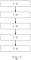
- FIG. 1 is a flowchart of a method for predicting a scattered signal of an X-ray for an examination object according to an embodiment of this application.
- the method for predicting a scattered signal of an X-ray for an examination object includes: Step S100: Scan each phantom in a scanning manner in which a scattering degree of each phantom in a plurality of phantoms is less than a reference scattering degree, so as to obtain first projection data of each phantom.
- the reference scattering degree refers to a scattering degree generated by scanning a phantom in a standard clinical mode, so that each phantom in the plurality of phantoms is scanned in the scanning manner in which the scattering degree of each phantom is less than the reference scattering degree, and a contribution of the scattered signal of the phantom is so small and can be neglected relative to absorption of the phantom.
- a scattering amount of the phantom is 0.01 times of an absorption amount of the phantom. That is, scattering in projection data obtained when the scattering degree of the phantom is less than the reference scattering degree has no impact on image quality and does not need to be considered.
- the first projection data may refer to projection data that can be considered as scatter-free projection data for the entire phantom.
- the scatter-free projection data of the phantom can be obtained by scanning the phantom in such a manner that the scattering degree of the phantom relative to the absorption degree of the phantom is so small and can be neglected.
- the first projection data of the phantom may be obtained by: performing segmented scanning on each of the plurality of phantoms with a first width less than a reference scanning width under a plurality of different scanning conditions to collect projection data of each first segment of each phantom with the first width under each scanning condition, where the reference scanning width is a width used when standard clinical scanning is performed; and obtaining the first projection data of each phantom under each scanning condition by connecting the projection data of each first segment of each phantom collected under each scanning condition.
- Different scanning conditions may include different phantom fading structures, different phantom positions, different scanning powers (energy), e.g., scanning kV, etc.
- a small collimator width (that is, the first width) is first used to collect a signal, which may be considered as a scatter-free real signal, and a small collimator is moved to collect all signals in a range of a detector. Then, scatter-free projection data (that is, the first projection data) of the entire phantom can be obtained by connecting signals collected by using each small collimator width.
- Step S101 Scan each phantom in a scanning manner in which the scattering degree of each phantom in the plurality of phantoms is equal to the reference scattering degree, so as to obtain second projection data of each phantom.
- the scattering degree generated when the phantom is scanned is the reference scattering degree generated when standard clinical scanning is performed. Scattering in the projection data of the phantom obtained during this scanning affects final image quality, and therefore cannot be neglected and should be removed.
- the second projection data may refer to scattered radiation that is included in the collected projection data and that affects image quality.
- each of the plurality of phantoms may be scanned with the reference scanning width under the plurality of different scanning conditions to collect the second projection data of each phantom under each scanning condition.
- different scanning conditions may include different phantom fading structures, different phantom positions, different scanning powers, e.g., scanning kV, etc.
- the collimator may be a sheet that is installed behind an X-ray generator of a CT imaging system and is configured to allow only X-rays from a specific direction range to scan and image the phantom
- the first and second projection data of the phantom may be, for example, distribution of absorption coefficients of the phantom under a certain projection.
- the phantom may be a simple phantom such as a water phantom; a diversified complex model such as a body phantom, for example, a head impersonation phantom or a lung impersonation phantom.
- Step S102 Obtain a real scattered signal of each phantom by subtracting the first projection data of each phantom from the second projection data of each phantom.
- the real scattered signal refers to a scattered signal value obtained when the phantom is scanned.
- Step S103 Train a learning model based on the second projection data of each phantom and the real scattered signal of each phantom to obtain a trained learning model.
- Real scattered signal values obtained in step S102 in each projection direction may be used as real values (signal 1) in training of the learning model by scanning diversified complex phantoms.
- the projection data of the phantom in each projection direction obtained in step S101 is used as a signal 2.
- a signal collected with a large collimator width may be used to obtain two-dimensional distribution (signal 2) of the absorption coefficients of the phantom in each projection direction.
- the learning model is trained based on the signal 1 and the signal 2, and a trained learning model may be obtained to predict a scattered signal of projection data of an X-ray for an examination object (e.g., one or some parts of a human body).
- pre-calculation processing may be performed on the second projection data of each phantom based on a physical model to obtain a calculated scattered signal of each phantom; and the learning model is trained by using the calculated scattered signal of each phantom and the real scattered signal of each phantom as training data.
- the calculated scattered signal may be a two-dimensional array
- the two-dimensional data may be used as an input to the learning model
- the signal 1 also as a two-dimensional array is used as an output of the learning model to perform pairing training on the learning model.
- learning algorithms for the learning model are not specifically required, such as but are not limited to, deep learning, such as neural network learning of convolutional neural networks and machine learning. There is also no special requirement for network selection.
- the first projection data of each phantom and the second projection data of each phantom refer to distribution of absorption coefficients collected from each phantom.
- data in the collected projection space is a transmitted X-ray, and each X-ray may be represented by using certain space-related absorption coefficient distribution.
- the signal 1 represents the real scattered signal obtained in step S102
- the signal 2 represents two-dimensional distribution of normalized absorption coefficients (that is, corresponding to the second projection data) of a scanned phantom under a certain projection (for brevity and clarity, only distribution of the absorption coefficients in a certain one-dimensional direction is shown), where the learning model may be trained by using the signals 1 and 2.
- a signal 3 indicates a scattered signal that needs to be corrected when the trained learning model is applied to the signal 2. Therefore, it can be learned that the scattered signal that needs to be corrected when the trained learning model is applied to the signal 2 is basically consistent with the real scattered signal.
- the learning model may be trained by using the calculated scattered signal (that is, a signal 2' shown in FIG. 5B ) generated by performing the foregoing physical model processing on the signal 2, and the signal 1 as training data, to simplify calculation complexity.
- Step S104 Apply the trained learning model to projection data of the X-ray for the examination object to predict the scattered signal in the projection data of the X-ray. Specifically, the projection data of the X-ray for the examination object is input into the learning model to generate a scattered signal prediction of the X-ray in the projection space.
- scattered projection data and scatter-free projection data may be collected under a plurality of different conditions for various types of complex phantoms (phantoms having different circumferences and heights), so as to provide sufficient and rich training data used to train the learning model, so that the method in this application can be applied to various systems, that is, is system-independent, and can be applied to scatter prediction under various conditions.
- the foregoing scatter correction method in this application may also be used in combination with a scattering reduction technology such as an anti-scatter grid.
- FIG. 2 shows an apparatus for predicting a scattered signal of an X-ray for an examination object according to an embodiment of this application.
- the apparatus 2 includes: a first obtaining module 20, configured to scan each phantom in a scanning manner in which a scattering degree of each phantom in a plurality of phantoms is less than a reference scattering degree, so as to obtain first projection data S1 of each phantom; a second obtaining module 21, configured to scan each phantom in a scanning manner in which the scattering degree of each phantom in the plurality of phantoms is equal to the reference scattering degree, so as to obtain second projection data S2 of each phantom; a subtraction module 22, configured to obtain a real scattered signal Sr of each phantom by subtracting the first projection data S1 of the phantom from the second projection data S2 of the phantom; a training module 23, configured to train a learning model based on the second projection
- the preprocessing phantom provides the calculated scattered signal obtained through physical model processing to the training phantom 23, so that the training phantom 23 trains the learning model by using the real scattered signal of the phantom and the calculated scattered signal of the phantom as the training data input and output.
- the first obtaining module 21 may perform an operation corresponding to the foregoing step S100 described with reference to FIG. 1
- the second obtaining module 22 may perform an operation corresponding to the foregoing step S101 described with reference to FIG. 1
- the subtraction module 23 may perform an operation corresponding to the foregoing step S102 described with reference to FIG. 1
- the training module 23 may perform an operation corresponding to the foregoing step S103 described with reference to FIG. 1
- the prediction module 24 may execute an operation corresponding to the foregoing step S104 described with reference to FIG. 1 .
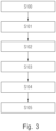
- FIG. 3 shows a method for correcting a scattered beam of an X-ray for an examination object according to an embodiment of this application.
- steps S100 to S104 are the same as steps S100 to S104 of FIG. 1 , and details are not described herein again.
- the method further includes step S105: correct the projection data of the X-ray for the examination object by using the predicted scattered signal to generate scatter-corrected projection data.
- the scatter-corrected projection data may be generated by subtracting the predicted scattered data from the projection data of the X-ray for the examination object (for example, a certain part of a human body in clinical practice, for example a head or a lung).
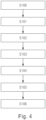
- FIG. 4 shows a method for reconstructing an image of an X-ray for an examination object according to an embodiment of this application.
- steps S100 to S104 are the same as steps S100 to S104 of FIG. 1
- step S105 is the same as step S105 of FIG. 3 , and details are not described herein again.
- the method further includes step S106: reconstruct the scatter-corrected projection data to generate a reconstructed X-ray image after scatter correction.
- FIG. 6A to FIG. 6E respectively verify the method of this application from aspects of a simple phantom (water phantom), a complex phantom (body phantom), and a real clinical image (head scanning).
- FIG. 6A shows a simple water phantom image
- FIG. 6B shows a head impersonation image
- FIG. 6C shows a lung impersonation image
- FIG. 6D shows a scanned image of a brain window of a head in clinic (a real person)
- FIG. 6E shows a scanned image of a bone window of a head in clinic (a real person)
- the left part of each figure is obtained by using a deep learning-based convolutional neural network-assisted scatter correction algorithm of this application, and the right part thereof is obtained by using an existing scatter correction algorithm.
- the foregoing method in this application may be implemented in a program manner.
- the program may be stored in a storage medium, and a computer may read the program from the storage medium, and execute the program to implement the foregoing method.
Landscapes
- Engineering & Computer Science (AREA)
- Physics & Mathematics (AREA)
- Theoretical Computer Science (AREA)
- General Physics & Mathematics (AREA)
- Biophysics (AREA)
- Evolutionary Computation (AREA)
- Artificial Intelligence (AREA)
- Biomedical Technology (AREA)
- Health & Medical Sciences (AREA)
- Computational Linguistics (AREA)
- Data Mining & Analysis (AREA)
- Life Sciences & Earth Sciences (AREA)
- General Health & Medical Sciences (AREA)
- Molecular Biology (AREA)
- Computing Systems (AREA)
- General Engineering & Computer Science (AREA)
- Mathematical Physics (AREA)
- Software Systems (AREA)
- Apparatus For Radiation Diagnosis (AREA)
Description
- This application generally relates to the technical field of computerized tomography (CT) projection signal correction and image processing, and more specifically, to a method for predicting a scattered signal of an X-ray based on a learning technology.
- Computerized tomography (CT) has been widely used in medical image fields. However, because scattered radiation is an intrinsic X-ray characteristic, scattered radiation rays that affect image quality are inevitably generated in a process of X-ray imaging of computerized tomography (CT). Scattered radiation rays deteriorate image quality in CT imaging.
- Usually, a CT system uses an anti-scatter grid (ASG) on detector hardware to reduce impact from a scattered signal. However, with use of an increasingly wide detector and pressure of hardware costs, CT manufacturers are more intended to calibrate the scattered signal by using a software algorithm.
- Various scatter correction algorithms and methods have been developed based on analysis models, which typically have more or less high calculation complexity, for example, some scatter correction algorithms and methods need to be simulated via iterative processes or statistics, such as Monte Carlo simulation. Scatter correction algorithms and methods developed based on analysis models, such as a Monte Carlo simulation-based algorithm, usually have high calculation complexity and require iterative processes and thus require much calculation and are therefore not widely used.
- In the current CT system, a convolution kernel algorithm based only on the raw data has been used, which is a simple and efficient scatter correction algorithm that does not involve an iterative method. However, the algorithm has a relatively strong model dependence and is difficult to extend for wider application. When contribution of scattered radiation becomes larger and scanning conditions become more complex, the current convolution kernel scatter correction algorithm is unable to predict a suitable scattered signal for all cases.
- In addition, convolution kernel design and modeling work is a key point of the current scatter correction algorithm, and is used to estimate distribution of scattering after coming out of an object scanned by an X-ray and reaching a detector. Each new system type usually needs to rely on simulation of system attributes and measurement of specified scattered signals from a representative phantom scanned under different scanning conditions. Then, based on the simulated and measured data, the convolution kernel is designed and model parameters are adjusted. For systems with a relatively large scattering contribution, more complex models must be applied to compensate for scattering effects for different situations.
-
EP 3 683 771 A1 -
US 2012/263360 A1 teaches an imaging apparatus and associated methods to efficiently estimate scatter during multi-fraction treatments for improved quality and workflow. Estimated scatter from one fraction during a treatment course can be utilized during subsequent fractions, allowing for measurements with higher scatter-to-primary ratios. -
US 2020/170607 A1 describes methods for correcting cone beam computed tomography signals to reduce scatter contamination contained therein. The methods involve generating a plurality of two-dimensional projection images of a subject from a three-dimensional multi-detector computed tomography image of the subject. This is followed by subtracting the plurality of two-dimensional projection images from a plurality of two-dimensional cone beam projection images of the subject to produce a plurality of two-dimensional estimated error projections that comprise an estimated error in the plurality of two-dimensional cone beam projection images. - A main objective of this application is to train a learning model by using real scattered signals of a phantom scanned under different scanning conditions and scatter fading data of an entire phantom obtained under different scanning conditions by using a standard clinical scanning width (that is, a reference scanning width mentioned in the following) as training data, so as to predict a corresponding scattered signal according to different scanning conditions (different object fading structures, different object positions, and different scanning powers (for example, kV)), so that a limitation that only a limited convolution kernel in a current convolution kernel algorithm can be used to predict a fixed scattered signal is removed, and more accurate scatter correction results can be obtained.
- To achieve the foregoing objective, according to one aspect of this application, a method for predicting a scattered signal of an X-ray for an examination object according to
claim 1 is provided. - In this specification, the reference scattering degree refers to a scattering degree generated by scanning a phantom in a standard clinical mode. In this manner, scatter-free projection data of a phantom is obtained by scanning the phantom in a scanning manner in which contribution of a scattered signal is so small and can be neglected. Scattered projection data of the phantom is obtained by scanning the phantom in a standard clinical mode. A real scattered signal of the phantom is obtained by subtracting the scattered projection data from the scatter-free projection data. The learning model is trained based on the real scattered signal of the phantom and the projection data under standard scanning of the phantom. All data used for training is measurement data of the phantom, that is, actual measurement data. Therefore, compared with a method for training a learning model based on analog data in the prior art, a more accurate scattered signal of projection data of an X-ray can be obtained.
- In addition, a data processing process of this application is not directly applied to an image, and therefore an image of an object does not need to be scanned. Therefore, the foregoing method has no impact on a structure of a current data processing pipeline, and all other calibration or correction steps (for correcting an effect of a system or a detector, etc.) remain the same. In addition, in the prior art, a method for performing scatter estimation according to an image generally has little or even no physical evidence. Therefore, it is difficult to control image quality (artifact or image noise). In contrast, in this application, performing scatter prediction according to projection data can avoid the foregoing problem.
- Further, according to an embodiment of this application, the training a learning model based on the second projection data of each phantom and the real scattered signal of each phantom to obtain a trained learning model includes: performing pre-calculation processing on the second projection data of each phantom based on a physical model to obtain a calculated scattered signal of each phantom; and training the learning model by using the calculated scattered signal of each phantom and the real scattered signal of each phantom as training data.
- In this manner, because the second projection data of each phantom is preprocessed based on the physical model, more physical evidence can be obtained in a scattered signal prediction process, thereby controlling image quality more easily.
- Further, according to an embodiment of this application, the calculated scattered signal of each phantom is used as input training data of the learning model, and the real scattered signal of each phantom is used as output training data of the learning model to train the learning model.
- In this manner, the calculated scattered signal is still calculated from the physical model with a calibration preprocessing program, so that the learning model is only used to learn real distribution of the generated scattered radiation on a specific system, thereby reducing learning complexity.
- The scanning each phantom in a scanning manner in which a scattering degree of each phantom in a plurality of phantoms is less than a reference scattering degree, so as to obtain first projection data of each phantom includes: performing segmented scanning on each of the plurality of phantoms with a first width less than a reference scanning width under a plurality of different scanning conditions to collect projection data of each first segment of each phantom with the first width under each scanning condition, where the reference scanning width is a width used when standard clinical scanning is performed; and obtaining the first projection data of each phantom under each scanning condition by connecting the projection data of each first segment of each phantom collected under each scanning condition.
- In this manner, the scatter-free projection data of the phantom can be obtained by performing segmented scanning on the phantom. For example, for a certain phantom, a small collimator width is first used to collect a signal, which may be considered as a scatter-free real signal, and a small collimator is moved to collect all signals in a range of a detector. Then, scatter-free projection data of the entire phantom can be obtained by connecting signals collected by using each small collimator width. In this way, precision of scatter-free projection data can be improved by controlling a collection width, so that suitable scatter-free projection data can be obtained. In addition, in this manner, specific scattered signals under different scanning conditions (different object fading structures, different object positions, and different scanning powers (kV)) can be predicted, so that a model obtained after learning training can compensate for scattering effects under different scanning conditions, and is also applicable to an existing CT system.
- The scanning each phantom in a scanning manner in which the scattering degree of each phantom in the plurality of phantoms is equal to the reference scattering degree, so as to obtain second projection data of each phantom includes: scanning each of the plurality of phantoms with the reference scanning width under the plurality of different scanning conditions to collect the second projection data of each phantom under each scanning condition.
- In this manner, for example, by collecting a signal (in a typical clinical mode) with a large collimator width for a certain phantom, required scattered projection data can be obtained by controlling the collection width according to a type of and an application a CT image system, thereby simplifying calculation complexity.
- Further, according to an embodiment of this application, the first projection data of each phantom and the second projection data of each phantom refer to distribution of absorption coefficients collected from each phantom.
- In this manner, the image of the object does not need to be scanned in the data processing process. Therefore, this does not affect the structure of the current data processing pipeline, and all other calibration or correction steps remain the same.
- Further, according to an embodiment of this application, the physical model is δ = γ - T 0 · exp (-κ · T), δ is the calculated scattered signal, T is a total absorption coefficient on the entire X-ray scanning path, T 0 is an absorption coefficient of each phantom, and κ and γ are model fitting parameters.
- In this manner, a calculated scattered signal with more physical evidence can be obtained, thereby improving prediction accuracy.
- Further, according to an embodiment of this application, the learning model includes machine learning with different network types and deep learning.
- In this manner, the method in this application may use various learning methods to perform scatter prediction, and any learning technology may be used in the method proposed in this application, for example, machine learning with different network types and deep learning such as a convolutional neural network.
- Further, according to an embodiment of this application, the plurality of different scanning conditions include at least one of the following: different phantom fading structures, different phantom positions, and different scanning powers.
- In this manner, even if the scanning conditions are complex and diverse, suitable scattered signals can be predicted for all cases.
- According to another aspect of this application, an apparatus for predicting a scattered signal of an X-ray for an examination object according to claim 8 is further provided.
- In this manner, the learning model is trained based on the real scattered signal of the phantom and the projection data of the phantom in the standard clinical mode. Therefore, because data used for training is measurement data of the phantom, that is, actually measured data, a more accurate scattered signal of the projection data of the X-ray can be obtained compared with a method for training a learning model based on analog data in the prior art.
- According to still another aspect of this application, a method for correcting a scattered beam of an X-ray for an examination object according to claim 9 is provided.
- In this manner, the learning model is trained based on the real scattered signal of the phantom and the projection data of the phantom in the standard clinical mode. Therefore, because data used for training is measurement data of the phantom, that is, actually measured data, a more accurate scattered signal of the projection data of the X-ray can be obtained and the scattered signal of the X-ray for the examination object can be more correctly corrected compared with a method for training a learning model based on analog data in the prior art.
- According to still another aspect of this application, a method for reconstructing an image of an X-ray for an examination object according to claim 10 is provided.
- In this manner, the learning model is trained based on the real scattered signal of the phantom and the projection data of the phantom in the standard clinical mode. Therefore, because data used for training is measurement data of the phantom, that is, actually measured data, a more accurate scattered signal in the projection data of the X-ray can be obtained compared with a method for training a learning model based on analog data in the prior art, thereby improving quality of a reconstructed X-ray image.
- According to still another aspect of this application, a computer storage medium storing a program according to claim 11 is provided. When being executed, the program causes a computer to perform the foregoing method.
- In the embodiments of this application, a learning model is trained by using real scattered signals of a phantom scanned under different scanning conditions and scatter fading data of an entire phantom obtained under different scanning conditions by using a standard clinical scanning width as training data, so as to predict a specific scattered signal according to different scanning conditions (different object fading structures, different object positions, and different scanning powers (for example, kV)), so that more accurate scatter correction results can be obtained. In the data processing process of this application, image data of a scanned object does not need to be used. Therefore, the foregoing method does not need an additional iterative processing process and has no impact on a structure of a current data processing pipeline, and all other calibration or correction steps (for correcting an effect of a system or a detector, etc.) remain the same. In addition, in this application, scatter prediction is performed according to projection data, which can avoid image quality problems such as artifacts.
- The accompanying drawings constituting a part of this application are used for providing further understanding for this application. Exemplary embodiments of this application and descriptions thereof are used for explaining this application and do not constitute any inappropriate limitation to this application. In the accompany drawings:
-
FIG. 1 is a flowchart of a method for predicting a scattered signal of an X-ray for an examination object according to an embodiment of this application. -
FIG. 2 is a block diagram of an apparatus for predicting a scattered signal of an X-ray for an examination object according to an embodiment of this application. -
FIG. 3 is a flowchart of a method for correcting a scattered beam of an X-ray for an examination object according to an embodiment of this application. -
FIG. 4 is a flowchart of a method for reconstructing an image of an X-ray for an examination object according to an embodiment of this application. -
FIG. 5A shows two-dimensional distribution of absorption coefficients of a scanned phantom under a certain projection, a scattered signal that needs to be corrected when a trained learning model is applied to two-dimensional distribution of absorption coefficients of a scanned phantom under a certain projection, and two-dimensional distribution of real scattered signals of a scanned phantom according to an embodiment of this application. -
FIG. 5B shows a calculated scattered signal obtained after pre-calculation processing of a physical model is performed on two-dimensional distribution of absorption coefficients of a scanned phantom under a certain projection, a scattered signal that needs to be corrected when a trained learning model is applied to two-dimensional distribution of absorption coefficients of a scanned phantom under a certain projection, and two-dimensional distribution of real scattered signals of a scanned phantom according to an embodiment of this application. -
FIG. 6A to FIG. 6E show comparisons between an image constructed by using the method inFIG. 4 in this application and an image obtained by using a currently used clinically verified algorithm in a CT system from aspects of a simple phantom (water phantom), a complex phantom (body phantom), and a real clinical image (head scanning). - It should be noted that the embodiments in this application and the features in the embodiments may be combined with each other in case of no conflicts. This application is described in detail below with reference to the drawings and the embodiments.
- It should be noted that, unless otherwise specified, all technical and scientific terms used herein have the same meaning as commonly understood by a person of ordinary skill in the art to which this application belongs.
- In this application, unless otherwise specified, orientation terms such as "up, down, top, and bottom" are generally used based on a direction shown in the accompanying drawings, or generally defined based on a vertical, perpendicular, or gravity direction; and similarly, for ease of understanding and description, "inside and outside" refer to inside and outside relative to a profile of a component. However, the foregoing orientation terms are not intended to limit this application.
-
FIG. 1 is a flowchart of a method for predicting a scattered signal of an X-ray for an examination object according to an embodiment of this application. As shown inFIG. 1 , the method for predicting a scattered signal of an X-ray for an examination object includes:
Step S100: Scan each phantom in a scanning manner in which a scattering degree of each phantom in a plurality of phantoms is less than a reference scattering degree, so as to obtain first projection data of each phantom. - In this step, the reference scattering degree refers to a scattering degree generated by scanning a phantom in a standard clinical mode, so that each phantom in the plurality of phantoms is scanned in the scanning manner in which the scattering degree of each phantom is less than the reference scattering degree, and a contribution of the scattered signal of the phantom is so small and can be neglected relative to absorption of the phantom. For example, a scattering amount of the phantom is 0.01 times of an absorption amount of the phantom. That is, scattering in projection data obtained when the scattering degree of the phantom is less than the reference scattering degree has no impact on image quality and does not need to be considered. Correspondingly, the first projection data may refer to projection data that can be considered as scatter-free projection data for the entire phantom.
- Specifically, the scatter-free projection data of the phantom can be obtained by scanning the phantom in such a manner that the scattering degree of the phantom relative to the absorption degree of the phantom is so small and can be neglected. In an implementation, the first projection data of the phantom may be obtained by: performing segmented scanning on each of the plurality of phantoms with a first width less than a reference scanning width under a plurality of different scanning conditions to collect projection data of each first segment of each phantom with the first width under each scanning condition, where the reference scanning width is a width used when standard clinical scanning is performed; and obtaining the first projection data of each phantom under each scanning condition by connecting the projection data of each first segment of each phantom collected under each scanning condition. Different scanning conditions may include different phantom fading structures, different phantom positions, different scanning powers (energy), e.g., scanning kV, etc.
- As a specific example, for a certain phantom, a small collimator width (that is, the first width) is first used to collect a signal, which may be considered as a scatter-free real signal, and a small collimator is moved to collect all signals in a range of a detector. Then, scatter-free projection data (that is, the first projection data) of the entire phantom can be obtained by connecting signals collected by using each small collimator width.
- Step S101: Scan each phantom in a scanning manner in which the scattering degree of each phantom in the plurality of phantoms is equal to the reference scattering degree, so as to obtain second projection data of each phantom.
- In this step, the scattering degree generated when the phantom is scanned is the reference scattering degree generated when standard clinical scanning is performed. Scattering in the projection data of the phantom obtained during this scanning affects final image quality, and therefore cannot be neglected and should be removed. Correspondingly, the second projection data may refer to scattered radiation that is included in the collected projection data and that affects image quality.
- In an implementation, each of the plurality of phantoms may be scanned with the reference scanning width under the plurality of different scanning conditions to collect the second projection data of each phantom under each scanning condition. Similarly, different scanning conditions may include different phantom fading structures, different phantom positions, different scanning powers, e.g., scanning kV, etc.
- As an instance, second projection data of a certain phantom is obtained by collecting a signal (in a clinically typical mode) with a large collimator width (i.e., a second width).
- In this specification, the collimator may be a sheet that is installed behind an X-ray generator of a CT imaging system and is configured to allow only X-rays from a specific direction range to scan and image the phantom, and the first and second projection data of the phantom may be, for example, distribution of absorption coefficients of the phantom under a certain projection. The phantom may be a simple phantom such as a water phantom; a diversified complex model such as a body phantom, for example, a head impersonation phantom or a lung impersonation phantom.
- Step S102: Obtain a real scattered signal of each phantom by subtracting the first projection data of each phantom from the second projection data of each phantom. In this step, the real scattered signal refers to a scattered signal value obtained when the phantom is scanned.
- Step S103: Train a learning model based on the second projection data of each phantom and the real scattered signal of each phantom to obtain a trained learning model.
- Real scattered signal values (e.g., two-dimensional arrays) obtained in step S102 in each projection direction may be used as real values (signal 1) in training of the learning model by scanning diversified complex phantoms. In addition, the projection data of the phantom in each projection direction obtained in step S101 is used as a
signal 2. For example, a signal collected with a large collimator width may be used to obtain two-dimensional distribution (signal 2) of the absorption coefficients of the phantom in each projection direction. The learning model is trained based on thesignal 1 and thesignal 2, and a trained learning model may be obtained to predict a scattered signal of projection data of an X-ray for an examination object (e.g., one or some parts of a human body). - In addition, in step S103, pre-calculation processing may be performed on the second projection data of each phantom based on a physical model to obtain a calculated scattered signal of each phantom; and the learning model is trained by using the calculated scattered signal of each phantom and the real scattered signal of each phantom as training data.
- For example, the calculated scattered signal may be a two-dimensional array, the two-dimensional data may be used as an input to the learning model, and the
signal 1 also as a two-dimensional array is used as an output of the learning model to perform pairing training on the learning model. In addition, learning algorithms for the learning model are not specifically required, such as but are not limited to, deep learning, such as neural network learning of convolutional neural networks and machine learning. There is also no special requirement for network selection. - As an example, the first projection data of each phantom and the second projection data of each phantom refer to distribution of absorption coefficients collected from each phantom. In other words, in this application, data in the collected projection space is a transmitted X-ray, and each X-ray may be represented by using certain space-related absorption coefficient distribution.
- The physical model is δ = γ · T 0 · exp (-κ · T), δ is the calculated scattered signal, T is a total absorption coefficient on the entire X-ray scanning path, T 0 is an absorption coefficient of each phantom, and κ and γ are model fitting parameters.
- As shown in
FIG. 5A , thesignal 1 represents the real scattered signal obtained in step S102, and thesignal 2 represents two-dimensional distribution of normalized absorption coefficients (that is, corresponding to the second projection data) of a scanned phantom under a certain projection (for brevity and clarity, only distribution of the absorption coefficients in a certain one-dimensional direction is shown), where the learning model may be trained by using thesignals FIG. 5A , asignal 3 indicates a scattered signal that needs to be corrected when the trained learning model is applied to thesignal 2. Therefore, it can be learned that the scattered signal that needs to be corrected when the trained learning model is applied to thesignal 2 is basically consistent with the real scattered signal. - In addition, as shown in
FIG. 5B , the learning model may be trained by using the calculated scattered signal (that is, a signal 2' shown inFIG. 5B ) generated by performing the foregoing physical model processing on thesignal 2, and thesignal 1 as training data, to simplify calculation complexity. - Step S104: Apply the trained learning model to projection data of the X-ray for the examination object to predict the scattered signal in the projection data of the X-ray. Specifically, the projection data of the X-ray for the examination object is input into the learning model to generate a scattered signal prediction of the X-ray in the projection space.
- In the foregoing method according to this application, scattered projection data and scatter-free projection data may be collected under a plurality of different conditions for various types of complex phantoms (phantoms having different circumferences and heights), so as to provide sufficient and rich training data used to train the learning model, so that the method in this application can be applied to various systems, that is, is system-independent, and can be applied to scatter prediction under various conditions.
- The foregoing scatter correction method in this application may also be used in combination with a scattering reduction technology such as an anti-scatter grid.
- Corresponding to the method shown in
FIG. 1 ,FIG. 2 shows an apparatus for predicting a scattered signal of an X-ray for an examination object according to an embodiment of this application. Theapparatus 2 includes: a first obtainingmodule 20, configured to scan each phantom in a scanning manner in which a scattering degree of each phantom in a plurality of phantoms is less than a reference scattering degree, so as to obtain first projection data S1 of each phantom; a second obtainingmodule 21, configured to scan each phantom in a scanning manner in which the scattering degree of each phantom in the plurality of phantoms is equal to the reference scattering degree, so as to obtain second projection data S2 of each phantom; asubtraction module 22, configured to obtain a real scattered signal Sr of each phantom by subtracting the first projection data S1 of the phantom from the second projection data S2 of the phantom; atraining module 23, configured to train a learning model based on the second projection data S2 of each phantom and the real scattered signal Sr of each phantom to obtain a trained learning model; and aprediction module 24, configured to apply the trained learning model to projection data of the X-ray for the examination object to predict the scattered signal in the projection data of the X-ray. - Preferably, before the second projection data S2 of each phantom is provided to the
training phantom 23, the second projection data S2 may be preprocessed by using a preprocessing module (not shown) by using a physical model, where the physical model may be δ = γ · T 0 · exp (-κ · T), δ is the calculated scattered signal, T is a total absorption coefficient on the entire X-ray scanning path, T 0 is an absorption coefficient of each phantom, and κ and γ are model fitting parameters. Then, the preprocessing phantom provides the calculated scattered signal obtained through physical model processing to thetraining phantom 23, so that thetraining phantom 23 trains the learning model by using the real scattered signal of the phantom and the calculated scattered signal of the phantom as the training data input and output. - In addition, it may be understood that the first obtaining
module 21 may perform an operation corresponding to the foregoing step S100 described with reference toFIG. 1 , the second obtainingmodule 22 may perform an operation corresponding to the foregoing step S101 described with reference toFIG. 1 , thesubtraction module 23 may perform an operation corresponding to the foregoing step S102 described with reference toFIG. 1 , thetraining module 23 may perform an operation corresponding to the foregoing step S103 described with reference toFIG. 1 , and theprediction module 24 may execute an operation corresponding to the foregoing step S104 described with reference toFIG. 1 . -
FIG. 3 shows a method for correcting a scattered beam of an X-ray for an examination object according to an embodiment of this application. In this method, steps S100 to S104 are the same as steps S100 to S104 ofFIG. 1 , and details are not described herein again. In addition, the method further includes step S105: correct the projection data of the X-ray for the examination object by using the predicted scattered signal to generate scatter-corrected projection data. In this step, the scatter-corrected projection data may be generated by subtracting the predicted scattered data from the projection data of the X-ray for the examination object (for example, a certain part of a human body in clinical practice, for example a head or a lung). -
FIG. 4 shows a method for reconstructing an image of an X-ray for an examination object according to an embodiment of this application. In this method, steps S100 to S104 are the same as steps S100 to S104 ofFIG. 1 , step S105 is the same as step S105 ofFIG. 3 , and details are not described herein again. In addition, the method further includes step S106: reconstruct the scatter-corrected projection data to generate a reconstructed X-ray image after scatter correction. - In addition, although the scatter prediction and correction involved in this application are applied to raw data in a certain projection direction, the image constructed based on the method provided in
FIG. 4 in this application is compared with an image obtained by using a clinically verified algorithm currently used by a CT system, and it is verified at an image level that a fading drift caused by scattered radiation can be well predicted by the prediction method provided in this application and suitable image quality can be obtained after the scattered signal is removed.FIG. 6A to FIG. 6E respectively verify the method of this application from aspects of a simple phantom (water phantom), a complex phantom (body phantom), and a real clinical image (head scanning).FIG. 6A shows a simple water phantom image,FIG. 6B shows a head impersonation image,FIG. 6C shows a lung impersonation image,FIG. 6D shows a scanned image of a brain window of a head in clinic (a real person), andFIG. 6E shows a scanned image of a bone window of a head in clinic (a real person), where the left part of each figure is obtained by using a deep learning-based convolutional neural network-assisted scatter correction algorithm of this application, and the right part thereof is obtained by using an existing scatter correction algorithm. - It can be learned from the figures that, images obtained by using the algorithm proposed in this application and images obtained by using the currently used clinically verified algorithm of the CT system are very close to each other, and images obtained by using both methods are based on same raw data. In the case of the simple water phantom images shown in
FIG. 6A , it can be seen through the comparison between the left and right parts inFIG. 6A that there is no difference in accuracy and uniformity of water values of the images obtained by using the two methods. In the case of the head impersonation images shown inFIG. 6B , it can be seen through comparison between the left and right parts inFIG. 6B that there is no visible difference in contrast, low contrast resolution, tissue shape structure, resolution, and noise level of the images obtained by using the two methods. In the case of the lung impersonation images shown inFIG. 6C , it can be seen through comparison between the left and right parts inFIG. 6C that there is no visible difference in high contrast resolution and tissue shape structure of the images obtained by using the two methods, and no extra artifact is visible in the image reconstructed by using the method in this application. In the case of the scanned image of a brain window of a head in clinic (a real person) shown inFIG. 6D , it can be seen through comparison between the left and right parts inFIG. 6D that there is no obvious difference in contrast (grey matter contrast), low contrast resolution, noise level, and tissue shape structure of the images obtained by using the two methods, and no artifact is visible in the image reconstructed by using the method in this application. In the case of the scanned image of a bone window of a head in clinic (a real person) shown inFIG. 6E , it can be seen through comparison between the left and right parts inFIG. 6E that the images obtained by using the two methods are not different in high contrast resolution (at an inner ear), image form details are consistent, and no artifact is visible in the image reconstructed by using the method in this application. - It can be learned from verification at the image level that quality of the X-ray image reconstructed in the manner in this application is similar to that of the image obtained by using the currently used clinically verified algorithm used in the CT system. For example, there is no visible difference in terms of image contrast, low contrast resolution, tissue morphology, resolution, and noise level, and there is no visible artifact. However, compared with the existing algorithm, the method in this application can simplify calculation complexity and doesn't rely on simulation of system attributes and measurement of a specified scattered signal by scanning a representative phantom under different scanning conditions. Therefore, the method in this application has better robustness.
- In addition, the foregoing method in this application may be implemented in a program manner. The program may be stored in a storage medium, and a computer may read the program from the storage medium, and execute the program to implement the foregoing method.
- The technology proposed in this application has at least the following technical effects:
- 1. Novel data training is proposed in this specification, that is, both input data and output data of a learning model are obtained from actual system measurement. By comparison, the learning model is trained based on simulated data in most current studies.
- 2. In this application, a learning method or a convolutional neural network (CNN) may not be completely used as a "black box" for entire scatter correction. For example, in the technology of this application, theoretical scattered radiation can be calculated by using a physical model in a data preprocessing process, so that a learning model such as the CNN is only used to learn distribution of generated scattered radiation.
- 3. The technology proposed in this application is not related to a separate system. The trained model is applicable to all systems with the same pattern type or configuration and therefore does not need to be adjusted during manufacturing.
- 4. The technology in this application is totally based on raw data, and the image of the object does not need to be scanned in the data processing process. Therefore, this does not affect the structure of the current data processing pipeline, and all other calibration or correction steps remain the same.
- 5. The technology in this application proposes a framework for performing scatter correction by using a learning method, and does not limit which learning technology to use. Machine learning with different network types and deep learning can be used in the framework proposed herein.
- Apparently, the described embodiments are only some embodiments rather than all the embodiments of this application. All other embodiments used by a person of ordinary skill in the art based on the embodiments of this application without creative efforts shall fall within the protection scope of this application, as defined by the appended claims.
- It should be noted that terms used herein are only for describing specific implementations and are not intended to limit exemplary implementations according to this application. As used herein, the singular form is intended to include the plural form, unless the context clearly indicates otherwise. In addition, it should further be understood that terms "comprise" and/or "include" used in this specification indicate that there are features, steps, operations, devices, components, and/or combinations thereof.
- It should be noted that, in the specification, claims, and accompanying drawings of this application, the terms "first", "second", and so on are intended to distinguish between similar objects but do not necessarily describe a specific order or sequence. It is to be understood that data used in this way is exchangeable in a proper case, so that the embodiments of this application described herein can be implemented in an order different from the order shown or described herein.
Claims (11)
- A computer-implemented method for predicting a scattered signal of an X-ray for an examination object, the method comprising:scanning (S100) each phantom in a scanning manner in which a scattering degree of each phantom in a plurality of phantoms is less than a reference scattering degree, so as to obtain first projection data (S1) of each phantom;scanning (S101) each phantom in a scanning manner in which the scattering degree of each phantom in the plurality of phantoms is equal to the reference scattering degree, so as to obtain second projection data (S2) of each phantom;obtaining (S102) a real scattered signal (Sr) of each phantom by subtracting the first projection data (S1) of the phantom from the second projection data (S2) of the phantom;training (S103) a learning model based on the second projection data (S2) of each phantom and the real scattered signal (Sr) of each phantom to obtain a trained learning model; andapplying (S104) the trained learning model to projection data of the X-ray for the examination object to predict the scattered signal in the projection data of the X-ray;wherein the scanning (S100) each phantom in a scanning manner in which a scattering degree of each phantom in a plurality of phantoms is less than a reference scattering degree, so as to obtain first projection data (S1) of each phantom comprises:performing segmented scanning on each of the plurality of phantoms with a first width less than a reference scanning width under a plurality of different scanning conditions to collect projection data of each first segment of each phantom with the first width under each scanning condition, wherein the reference scanning width is a width used when standard clinical scanning is performed; andobtaining the first projection data (S1) of each phantom under each scanning condition by connecting the projection data of each first segment of each phantom collected under each scanning condition;wherein the scanning (S105) each phantom in a scanning manner in which the scattering degree of each phantom in the plurality of phantoms is equal to the reference scattering degree, so as to obtain second projection data (S2) of each phantom comprises:
scanning each of the plurality of phantoms with the reference scanning width under the plurality of different scanning conditions to collect the second projection data (S2) of each phantom under each scanning condition. - The method according to claim 1, wherein the training (S103) a learning model based on the second projection data (S2) of each phantom and the real scattered signal (Sr) of each phantom to obtain a trained learning model comprises:performing pre-calculation processing on the second projection data (S2) of each phantom based on a physical model to obtain a calculated scattered signal of each phantom; andtraining the learning model by using the calculated scattered signal of each phantom and the real scattered signal (Sr) of each phantom as training data.
- The method according to claim 2, wherein the calculated scattered signal of each phantom is used as input training data of the learning model, and the real scattered signal (Sr) of each phantom is used as output training data of the learning model to train the learning model.
- The method according to claim 1, wherein the first projection data (S1) of each phantom and the second projection data (S2) of each phantom refer to distribution of absorption coefficients collected from each phantom.
- The method according to claim 2 or 4, wherein the physical model is δ = γ · T 0 · exp (-κ · T), δ is the calculated scattered signal, T is a total absorption coefficient on the entire X-ray scanning path, T 0 is an absorption coefficient of each phantom, and κ and γ are model fitting parameters.
- The method according to claim 1, wherein the learning model comprises machine learning with different network types and deep learning.
- The method according to claim 1, wherein the plurality of different scanning conditions comprise at least one of the following: different phantom fading structures, different phantom positions, and different scanning powers.
- An apparatus (2) for predicting a scattered signal of an X-ray for an examination object, the apparatus (2) comprising:A first obtaining module (20), configured to scan each phantom in a scanning manner in which a scattering degree of each phantom in a plurality of phantoms is less than a reference scattering degree, so as to obtain first projection data (S1) of each phantom;a second obtaining module (21), configured to scan each phantom in a scanning manner in which the scattering degree of each phantom in the plurality of phantoms is equal to the reference scattering degree, so as to obtain second projection data (S2) of each phantom;a subtraction module (22), configured to obtain a real scattered signal (Sr) of each phantom by subtracting the first projection data (S1) of the phantom from the second projection data (S2) of the phantom;a training module (23), configured to train a learning model based on the second projection data (S2) of each phantom and the real scattered signal (Sr) of each phantom to obtain a trained learning model; anda prediction module (24), configured to apply the trained learning model to projection data of the X-ray for the examination object to predict the scattered signal in the projection data of the X-raywherein the scanning (S100) each phantom in a scanning manner in which a scattering degree of each phantom in a plurality of phantoms is less than a reference scattering degree, so as to obtain first projection data (S1) of each phantom comprises:performing segmented scanning on each of the plurality of phantoms with a first width less than a reference scanning width under a plurality of different scanning conditions to collect projection data of each first segment of each phantom with the first width under each scanning condition, wherein the reference scanning width is a width used when standard clinical scanning is performed; andobtaining the first projection data (S1) of each phantom under each scanning condition by connecting the projection data of each first segment of each phantom collected under each scanning condition,wherein the scanning (S105) each phantom in a scanning manner in which the scattering degree of each phantom in the plurality of phantoms is equal to the reference scattering degree, so as to obtain second projection data (S2) of each phantom comprises:
scanning each of the plurality of phantoms with the reference scanning width under the plurality of different scanning conditions to collect the second projection data (S2) of each phantom under each scanning condition. - A computer-implemented method for correcting a scattered beam of an X-ray for an examination object, the method comprising the steps of the method for predicting a scattered signal according to claim 1; and
correcting (S105) the projection data of the X-ray for the examination object by using the predicted scattered signal to generate scatter-corrected projection data. - A computer-implementedmethod for reconstructing an image of an X-ray for an examination object, the method comprising the steps of the method for correcting a scattered beam according to claim 9; andreconstructing the scatter-corrected projection data to generate a reconstructed computerized tomography image after scatter correction.
- A computer storage medium storing a program that, when executed, causes a computer to perform the method according to any one of claims 1 to 7, 9, and 10.
Applications Claiming Priority (2)
| Application Number | Priority Date | Filing Date | Title |
|---|---|---|---|
| CN202110110542.4A CN114820833B (en) | 2021-01-27 | 2021-01-27 | Method and device for predicting X-ray scattered signals and method for correcting scattered beams |
| PCT/CN2021/118560 WO2022160735A1 (en) | 2021-01-27 | 2021-09-15 | Method and apparatus for predicting scattered signal of x-ray, and method for correcting scattered beam |
Publications (4)
| Publication Number | Publication Date |
|---|---|
| EP4268192A1 EP4268192A1 (en) | 2023-11-01 |
| EP4268192B1 true EP4268192B1 (en) | 2025-04-30 |
| EP4268192C0 EP4268192C0 (en) | 2025-04-30 |
| EP4268192B8 EP4268192B8 (en) | 2025-06-11 |
Family
ID=78371707
Family Applications (1)
| Application Number | Title | Priority Date | Filing Date |
|---|---|---|---|
| EP21798265.1A Active EP4268192B8 (en) | 2021-01-27 | 2021-09-15 | Method and apparatus for predicting scattered signal of x-ray, and method for correcting scattered beam |
Country Status (4)
| Country | Link |
|---|---|
| US (1) | US12592015B2 (en) |
| EP (1) | EP4268192B8 (en) |
| CN (1) | CN114820833B (en) |
| WO (1) | WO2022160735A1 (en) |
Family Cites Families (11)
| Publication number | Priority date | Publication date | Assignee | Title |
|---|---|---|---|---|
| JP5663245B2 (en) * | 2010-09-07 | 2015-02-04 | 株式会社日立メディコ | X-ray CT system |
| US8705827B2 (en) * | 2011-04-15 | 2014-04-22 | Georgia Tech Research Corporation | Scatter correction methods |
| US10977843B2 (en) * | 2017-06-28 | 2021-04-13 | Shanghai United Imaging Healthcare Co., Ltd. | Systems and methods for determining parameters for medical image processing |
| CN111526796B (en) * | 2017-12-29 | 2023-08-25 | 上海联影医疗科技股份有限公司 | Systems and methods for image scatter correction |
| CN108606805B (en) * | 2018-03-15 | 2022-02-11 | 东软医疗系统股份有限公司 | A kind of scattering correction method, device and equipment |
| JP7649240B2 (en) | 2018-11-30 | 2025-03-19 | アキュレイ インコーポレイテッド | Multimodal Radiation Devices and Methods |
| CN109717891B (en) * | 2018-12-29 | 2024-07-26 | 浙江明峰智能医疗科技有限公司 | PET scattering correction method based on deep learning |
| US10937206B2 (en) * | 2019-01-18 | 2021-03-02 | Canon Medical Systems Corporation | Deep-learning-based scatter estimation and correction for X-ray projection data and computer tomography (CT) |
| US11241212B2 (en) * | 2019-03-05 | 2022-02-08 | Canon Medical Systems Corporation | Medical apparatus |
| CN110097611B (en) * | 2019-04-28 | 2023-09-22 | 上海联影智能医疗科技有限公司 | Image reconstruction method, device, equipment and storage medium |
| CN111833410A (en) * | 2020-07-07 | 2020-10-27 | 南京革佳智能科技有限公司 | X-ray scattering suppression method based on deep learning |
-
2021
- 2021-01-27 CN CN202110110542.4A patent/CN114820833B/en active Active
- 2021-09-15 WO PCT/CN2021/118560 patent/WO2022160735A1/en not_active Ceased
- 2021-09-15 EP EP21798265.1A patent/EP4268192B8/en active Active
- 2021-09-15 US US18/262,849 patent/US12592015B2/en active Active
Also Published As
| Publication number | Publication date |
|---|---|
| CN114820833A (en) | 2022-07-29 |
| EP4268192B8 (en) | 2025-06-11 |
| WO2022160735A1 (en) | 2022-08-04 |
| US12592015B2 (en) | 2026-03-31 |
| EP4268192C0 (en) | 2025-04-30 |
| US20240312076A1 (en) | 2024-09-19 |
| EP4268192A1 (en) | 2023-11-01 |
| CN114820833B (en) | 2025-10-03 |
Similar Documents
| Publication | Publication Date | Title |
|---|---|---|
| Hansen et al. | ScatterNet: a convolutional neural network for cone‐beam CT intensity correction | |
| Lei et al. | Learning‐based CBCT correction using alternating random forest based on auto‐context model | |
| US8705827B2 (en) | Scatter correction methods | |
| Niu et al. | Shading correction for on‐board cone‐beam CT in radiation therapy using planning MDCT images | |
| US8144829B2 (en) | Cone-beam CT imaging scheme | |
| US9307949B2 (en) | X-ray CT device and method for correcting scattered X-rays | |
| US8818065B2 (en) | Methods and apparatus for scatter correction for CBCT system and cone-beam image reconstruction | |
| US7103139B2 (en) | X-ray CT device and image displaying method therefor | |
| US20130202079A1 (en) | System and Method for Controlling Radiation Dose for Radiological Applications | |
| KR102020221B1 (en) | Scatter Correction Method and Apparatus of Cone-beam CT for Dental Treatment | |
| US20180330233A1 (en) | Machine learning based scatter correction | |
| CN115797485B (en) | Image artifact removal methods, systems, electronic devices and storage media | |
| US10194884B2 (en) | Reducing image artifacts | |
| JP5590548B2 (en) | X-ray CT image processing method, X-ray CT program, and X-ray CT apparatus equipped with the program | |
| CN103578082A (en) | Cone beam CT scatter correction method and system | |
| Paudel et al. | Evaluation of normalized metal artifact reduction (NMAR) in kVCT using MVCT prior images for radiotherapy treatment planning | |
| US12053320B2 (en) | Computer-implemented method, computer program, systems and x-ray facility for correction of x-ray image data with regard to noise effects | |
| CN113177991A (en) | Method for correcting scattering artifacts in CBCT (cone beam computed tomography) based on planned CT (computed tomography) | |
| JP6446361B2 (en) | X-ray CT apparatus and correction processing apparatus | |
| EP4354395A1 (en) | Artificial intelligence-based dual energy x-ray image motion correction training method and system | |
| Trapp et al. | Empirical scatter correction: CBCT scatter artifact reduction without prior information | |
| CN110175957A (en) | Multipotency amount CT sill substance decomposition method | |
| JP2020179146A (en) | Medical image processing equipment, X-ray computed tomography equipment and programs | |
| US8938104B2 (en) | Systems and methods for adaptive filtering | |
| Fan et al. | Image‐domain shading correction for cone‐beam CT without prior patient information |
Legal Events
| Date | Code | Title | Description |
|---|---|---|---|
| STAA | Information on the status of an ep patent application or granted ep patent |
Free format text: STATUS: UNKNOWN |
|
| STAA | Information on the status of an ep patent application or granted ep patent |
Free format text: STATUS: THE INTERNATIONAL PUBLICATION HAS BEEN MADE |
|
| PUAI | Public reference made under article 153(3) epc to a published international application that has entered the european phase |
Free format text: ORIGINAL CODE: 0009012 |
|
| STAA | Information on the status of an ep patent application or granted ep patent |
Free format text: STATUS: REQUEST FOR EXAMINATION WAS MADE |
|
| 17P | Request for examination filed |
Effective date: 20230726 |
|
| AK | Designated contracting states |
Kind code of ref document: A1 Designated state(s): AL AT BE BG CH CY CZ DE DK EE ES FI FR GB GR HR HU IE IS IT LI LT LU LV MC MK MT NL NO PL PT RO RS SE SI SK SM TR |
|
| DAV | Request for validation of the european patent (deleted) | ||
| DAX | Request for extension of the european patent (deleted) | ||
| STAA | Information on the status of an ep patent application or granted ep patent |
Free format text: STATUS: EXAMINATION IS IN PROGRESS |
|
| 17Q | First examination report despatched |
Effective date: 20240822 |
|
| GRAP | Despatch of communication of intention to grant a patent |
Free format text: ORIGINAL CODE: EPIDOSNIGR1 |
|
| STAA | Information on the status of an ep patent application or granted ep patent |
Free format text: STATUS: GRANT OF PATENT IS INTENDED |
|
| INTG | Intention to grant announced |
Effective date: 20250204 |
|
| GRAS | Grant fee paid |
Free format text: ORIGINAL CODE: EPIDOSNIGR3 |
|
| GRAA | (expected) grant |
Free format text: ORIGINAL CODE: 0009210 |
|
| STAA | Information on the status of an ep patent application or granted ep patent |
Free format text: STATUS: THE PATENT HAS BEEN GRANTED |
|
| AK | Designated contracting states |
Kind code of ref document: B1 Designated state(s): AL AT BE BG CH CY CZ DE DK EE ES FI FR GB GR HR HU IE IS IT LI LT LU LV MC MK MT NL NO PL PT RO RS SE SI SK SM TR |
|
| REG | Reference to a national code |
Ref country code: CH Ref legal event code: EP Ref country code: GB Ref legal event code: FG4D |
|
| RAP4 | Party data changed (patent owner data changed or rights of a patent transferred) |
Owner name: SIEMENS SHANGHAI MEDICAL EQUIPMENT LTD. |
|
| REG | Reference to a national code |
Ref country code: CH Ref legal event code: PK Free format text: BERICHTIGUNG B8 Ref country code: DE Ref legal event code: R096 Ref document number: 602021030105 Country of ref document: DE |
|
| REG | Reference to a national code |
Ref country code: IE Ref legal event code: FG4D |
|
| U01 | Request for unitary effect filed |
Effective date: 20250502 |
|
| U07 | Unitary effect registered |
Designated state(s): AT BE BG DE DK EE FI FR IT LT LU LV MT NL PT RO SE SI Effective date: 20250508 |
|
| PG25 | Lapsed in a contracting state [announced via postgrant information from national office to epo] |
Ref country code: ES Free format text: LAPSE BECAUSE OF FAILURE TO SUBMIT A TRANSLATION OF THE DESCRIPTION OR TO PAY THE FEE WITHIN THE PRESCRIBED TIME-LIMIT Effective date: 20250430 |
|
| PG25 | Lapsed in a contracting state [announced via postgrant information from national office to epo] |
Ref country code: NO Free format text: LAPSE BECAUSE OF FAILURE TO SUBMIT A TRANSLATION OF THE DESCRIPTION OR TO PAY THE FEE WITHIN THE PRESCRIBED TIME-LIMIT Effective date: 20250730 Ref country code: GR Free format text: LAPSE BECAUSE OF FAILURE TO SUBMIT A TRANSLATION OF THE DESCRIPTION OR TO PAY THE FEE WITHIN THE PRESCRIBED TIME-LIMIT Effective date: 20250731 |
|
| PG25 | Lapsed in a contracting state [announced via postgrant information from national office to epo] |
Ref country code: PL Free format text: LAPSE BECAUSE OF FAILURE TO SUBMIT A TRANSLATION OF THE DESCRIPTION OR TO PAY THE FEE WITHIN THE PRESCRIBED TIME-LIMIT Effective date: 20250430 |
|
| PG25 | Lapsed in a contracting state [announced via postgrant information from national office to epo] |
Ref country code: HR Free format text: LAPSE BECAUSE OF FAILURE TO SUBMIT A TRANSLATION OF THE DESCRIPTION OR TO PAY THE FEE WITHIN THE PRESCRIBED TIME-LIMIT Effective date: 20250430 |
|
| PG25 | Lapsed in a contracting state [announced via postgrant information from national office to epo] |
Ref country code: RS Free format text: LAPSE BECAUSE OF FAILURE TO SUBMIT A TRANSLATION OF THE DESCRIPTION OR TO PAY THE FEE WITHIN THE PRESCRIBED TIME-LIMIT Effective date: 20250731 |
|
| PG25 | Lapsed in a contracting state [announced via postgrant information from national office to epo] |
Ref country code: IS Free format text: LAPSE BECAUSE OF FAILURE TO SUBMIT A TRANSLATION OF THE DESCRIPTION OR TO PAY THE FEE WITHIN THE PRESCRIBED TIME-LIMIT Effective date: 20250830 |
|
| U20 | Renewal fee for the european patent with unitary effect paid |
Year of fee payment: 5 Effective date: 20250919 |
|
| PG25 | Lapsed in a contracting state [announced via postgrant information from national office to epo] |
Ref country code: SM Free format text: LAPSE BECAUSE OF FAILURE TO SUBMIT A TRANSLATION OF THE DESCRIPTION OR TO PAY THE FEE WITHIN THE PRESCRIBED TIME-LIMIT Effective date: 20250430 |
|
| PG25 | Lapsed in a contracting state [announced via postgrant information from national office to epo] |
Ref country code: CZ Free format text: LAPSE BECAUSE OF FAILURE TO SUBMIT A TRANSLATION OF THE DESCRIPTION OR TO PAY THE FEE WITHIN THE PRESCRIBED TIME-LIMIT Effective date: 20250430 |
|
| PG25 | Lapsed in a contracting state [announced via postgrant information from national office to epo] |
Ref country code: SK Free format text: LAPSE BECAUSE OF FAILURE TO SUBMIT A TRANSLATION OF THE DESCRIPTION OR TO PAY THE FEE WITHIN THE PRESCRIBED TIME-LIMIT Effective date: 20250430 |
|
| PLBE | No opposition filed within time limit |
Free format text: ORIGINAL CODE: 0009261 |
|
| STAA | Information on the status of an ep patent application or granted ep patent |
Free format text: STATUS: NO OPPOSITION FILED WITHIN TIME LIMIT |
|
| REG | Reference to a national code |
Ref country code: CH Ref legal event code: L10 Free format text: ST27 STATUS EVENT CODE: U-0-0-L10-L00 (AS PROVIDED BY THE NATIONAL OFFICE) Effective date: 20260311 |
|
| 26N | No opposition filed |
Effective date: 20260202 |
|
| REG | Reference to a national code |
Ref country code: CH Ref legal event code: H13 Free format text: ST27 STATUS EVENT CODE: U-0-0-H10-H13 (AS PROVIDED BY THE NATIONAL OFFICE) Effective date: 20260504 |