EP4267412B1 - A tire tread - Google Patents
A tire tread Download PDFInfo
- Publication number
- EP4267412B1 EP4267412B1 EP20842329.3A EP20842329A EP4267412B1 EP 4267412 B1 EP4267412 B1 EP 4267412B1 EP 20842329 A EP20842329 A EP 20842329A EP 4267412 B1 EP4267412 B1 EP 4267412B1
- Authority
- EP
- European Patent Office
- Prior art keywords
- covering layer
- material constituting
- modulus
- contact element
- orientation
- Prior art date
- Legal status (The legal status is an assumption and is not a legal conclusion. Google has not performed a legal analysis and makes no representation as to the accuracy of the status listed.)
- Active
Links
Images


Classifications
-
- B—PERFORMING OPERATIONS; TRANSPORTING
- B60—VEHICLES IN GENERAL
- B60C—VEHICLE TYRES; TYRE INFLATION; TYRE CHANGING; CONNECTING VALVES TO INFLATABLE ELASTIC BODIES IN GENERAL; DEVICES OR ARRANGEMENTS RELATED TO TYRES
- B60C11/00—Tyre tread bands; Tread patterns; Anti-skid inserts
- B60C11/0041—Tyre tread bands; Tread patterns; Anti-skid inserts comprising different tread rubber layers
-
- B—PERFORMING OPERATIONS; TRANSPORTING
- B60—VEHICLES IN GENERAL
- B60C—VEHICLE TYRES; TYRE INFLATION; TYRE CHANGING; CONNECTING VALVES TO INFLATABLE ELASTIC BODIES IN GENERAL; DEVICES OR ARRANGEMENTS RELATED TO TYRES
- B60C11/00—Tyre tread bands; Tread patterns; Anti-skid inserts
- B60C11/0008—Tyre tread bands; Tread patterns; Anti-skid inserts characterised by the tread rubber
-
- B—PERFORMING OPERATIONS; TRANSPORTING
- B60—VEHICLES IN GENERAL
- B60C—VEHICLE TYRES; TYRE INFLATION; TYRE CHANGING; CONNECTING VALVES TO INFLATABLE ELASTIC BODIES IN GENERAL; DEVICES OR ARRANGEMENTS RELATED TO TYRES
- B60C11/00—Tyre tread bands; Tread patterns; Anti-skid inserts
- B60C11/03—Tread patterns
- B60C11/13—Tread patterns characterised by the groove cross-section, e.g. for buttressing or preventing stone-trapping
- B60C11/1307—Tread patterns characterised by the groove cross-section, e.g. for buttressing or preventing stone-trapping with special features of the groove walls
- B60C11/1346—Tread patterns characterised by the groove cross-section, e.g. for buttressing or preventing stone-trapping with special features of the groove walls covered by a rubber different from the tread rubber
-
- B—PERFORMING OPERATIONS; TRANSPORTING
- B60—VEHICLES IN GENERAL
- B60C—VEHICLE TYRES; TYRE INFLATION; TYRE CHANGING; CONNECTING VALVES TO INFLATABLE ELASTIC BODIES IN GENERAL; DEVICES OR ARRANGEMENTS RELATED TO TYRES
- B60C11/00—Tyre tread bands; Tread patterns; Anti-skid inserts
- B60C11/03—Tread patterns
- B60C11/0306—Patterns comprising block rows or discontinuous ribs
-
- B—PERFORMING OPERATIONS; TRANSPORTING
- B60—VEHICLES IN GENERAL
- B60C—VEHICLE TYRES; TYRE INFLATION; TYRE CHANGING; CONNECTING VALVES TO INFLATABLE ELASTIC BODIES IN GENERAL; DEVICES OR ARRANGEMENTS RELATED TO TYRES
- B60C11/00—Tyre tread bands; Tread patterns; Anti-skid inserts
- B60C11/0008—Tyre tread bands; Tread patterns; Anti-skid inserts characterised by the tread rubber
- B60C2011/0016—Physical properties or dimensions
-
- B—PERFORMING OPERATIONS; TRANSPORTING
- B60—VEHICLES IN GENERAL
- B60C—VEHICLE TYRES; TYRE INFLATION; TYRE CHANGING; CONNECTING VALVES TO INFLATABLE ELASTIC BODIES IN GENERAL; DEVICES OR ARRANGEMENTS RELATED TO TYRES
- B60C11/00—Tyre tread bands; Tread patterns; Anti-skid inserts
- B60C11/0008—Tyre tread bands; Tread patterns; Anti-skid inserts characterised by the tread rubber
- B60C2011/0016—Physical properties or dimensions
- B60C2011/0025—Modulus or tan delta
Definitions
- the present invention relates to a tread for a tire, in particular to a tread for a tire for providing improvement of performance on non-wintry surface while maintaining performance on wintry surface.
- introducing a hard layer onto a side face of a block is effective as the hard layer introduced onto the side face of the block increases efficiently so-called an edge pressure.
- WO2013088570 discloses a tread for a pneumatic tire in which a reinforcing layer is provided on a side wall portion of a ground-contacting element of a tread of a tire for improving performance on wintry surface, and in a pneumatic tire having such a tread, the reinforcing layer has a mean thickness of less than 0.5 mm, is provided over an area at least equal to 50% of the side wall portion, and has a material modulus at least equal to 200 MPa
- JP1995-047814 discloses a tread for a tire having reinforcing layers using rubber having a JIS A hardness of 80 to 95 degrees on block side walls facing a transverse groove and an auxiliary groove, in a block provided with three narrow incisions and one auxiliary groove for improving performance on wintry surface.
- JP2010-105509 discloses a tire provided with a composition in which 50 parts or more by weight of at least one of carbon black and silica is combined with 100 parts by weight of a diene rubber containing 30% or more by weight of a rubber component having a glass transition temperature at least equal to -60°C, and providing reinforcing layers employing rubber having a brittleness temperature at most equal to -30°C on the side walls of the blocks for improving performance on both wintry and non-wintry surfaces.
- a "radial direction/orientation” is a direction/orientation perpendicular to axis of rotation of the tire. This direction/orientation corresponds to thickness orientation of the tread.
- An "axial direction/orientation” is a direction/orientation parallel to axis of rotation of the tire.
- a "circumferential direction/orientation” is a direction/orientation which is tangential to any circle centered on axis of rotation. This direction/orientation is perpendicular to both the axial direction/orientation and the radial direction/orientation.
- a "tire” means all types of elastic tire whether or not subjected to an internal pressure.
- a "tread" of a tire means a quantity of rubber material bounded by lateral surfaces and by two main surfaces one of which is intended to come into contact with ground when the tire is rolling.
- a "groove” is a space between two rubber faces/sidewalls which do not contact between themselves under usual rolling condition connected by another rubber face/ bottom.
- a groove has a width and a depth.
- An “incision”, also referred to as a “sipe” is a narrow cutout formed toward radially inwardly from a surface of a tread made by, for example a thin blade having a shape like a knife blade.
- a width of the incision at the surface of the tread is narrower than a groove, for example less than or equal to 2.0mm. this incision may, different from the groove, be partly or completely closed when such the incision is in a contact patch and under usual rolling condition.
- a “contact patch” is a footprint of a tire mounted onto its standard rim as identified in tire standards such as ETRTO, JATMA or TRA, and inflated at its nominal pressure and under its nominal load.
- a “width TW” of a contact face is a maximum contact width of the contact patch along with an axis of rotation of the tire.
- a modulus G* is the dynamic shear complex modulus of the material at 60°C.
- the storage elastic modulus represented by G' and the loss elastic modulus represented by G" which are well known dynamic properties for one skilled in the art, are measured by means of a viscosity analyzer (microanalyzer: Metravib VB4000) using a test piece molded from the raw composition or a test piece which is combined with the composition after vulcanization.
- the test piece that is used is one that is described in Figure X2.1 (a circular method) of the standard ASTM D 5992-96 (version published September 2006, initially approved in 1996).
- the diameter'd' of the test piece is 10 mm (consequently the test piece has a circular cross section of 78.5 mm2), the thickness 'L' of each part of the rubber compound is 2 mm, and the ratio 'd/L' (described in paragraph X2.4 of the ASTM standard, in contrast to the ratio 'd/L' of 2 recommended in the standard ISO 2856) is 5.
- the response of a test piece comprising a vulcanized rubber composition subjected to a simple alternating sinusoidal shear load is measured at a frequency of 10 Hz.
- the maximum shear stress imposed during the test is 0.7 MPa.
- the test is conducted by varying the temperature from Tmin, which is a temperature lower than the glass transition temperature (Tg) of the rubber material, to a maximum temperature Tmax, in the vicinity of 100°C, at a rate of 1.5°C per minute.
- Tmin glass transition temperature
- Tmax glass transition temperature
- the test piece is stabilized for approximately 20 minutes at Tmin prior to the start of the test in order to obtain a satisfactory uniformity of temperature within the test piece.
- the results obtained are the storage elastic modulus (G') and the loss elastic modulus (G”) at the prescribed temperature.
- the present invention provides a tread for a tire having a contact face intended to come into contact with ground during rolling, the tread being provided with at least one principal groove of a depth Dp, and a plurality of sub grooves of a depth Ds extending in an orientation with an angle relative to an orientation the at least one principal groove being extending, the at least one principal groove and the plurality of sub grooves delimiting a plurality of contact elements, a material constituting the plurality of contact elements having a modulus G* at 60°C Mb and a glass transition temperature Tgb, at least one of a contact element among the plurality of contact elements being provided with a covering layer covering at least one of a lateral face of the contact element facing to circumferential orientation at least partly, the covering layer consists of at least two layers, an outer covering layer facing to outward of the contact element, a material constituting the outer covering layer has a modulus G* at 60°C Mo and a glass transition temperature Tgo, and an inner covering layer facing to inward of the contact element, a
- This arrangement provides an improvement of performance on non-wintry surface at wide range of temperature while maintaining or even still improving performance on wintry surface.
- the covering layer Since at least one of the contact element is provided with the covering layer covering at least one of the lateral face of the contact element facing to circumferential orientation at least partly, the covering layer generates a good edge effect especially on wintry surface. Therefore it is possible to improve performance on wintry surface.
- the covering layer consists of at least two layers, the outer covering layer facing to outward of the contact element, the material constituting the outer covering layer has the modulus G* at 60°C Mo and the glass transition temperature Tgo, and the inner covering layer facing to inward of the contact element, the material constituting the inner covering layer has the modulus G* at 60°C Mi and the glass transition temperature Tgi, the covering layer can adapt wide range of temperature in particular on non-wintry surface by combining different modulus G* and different glass transition temperature. Therefore it is possible to improve performance on non-wintry surface at wide range of temperature.
- the modulus G* at 60°C Mb of the material constituting the contact element is higher than the modulus G* at 60°C Mi of the material constituting the inner covering layer
- the modulus G* at 60°C Mo of the material constituting the outer covering layer is higher than the modulus G* at 60°C Mb of the material constituting the contact element and/or the glass transition temperature Tgb of the material constituting the contact element is higher than the glass transition temperature Tgi of the material constituting the inner covering layer
- the glass transition temperature Tgo of the material constituting the outer covering layer is higher than the glass transition temperature Tgb of the material constituting the contact element
- the modulus G* at 60°C Mo of the material constituting the outer covering layer higher than the modulus G* at 60°C Mb of the material constituting the contact element enables to generate efficiently the edge effect especially on wintry surface and on non-wintry surface with relatively lower temperature
- a thickness of the covering layer measured on a plane parallel to the contact face in an orientation perpendicular to an extending orientation of the principal groove or the sub groove in which the covering layer is facing is at most equal to 2.0 mm.
- the thickness of the covering layer is more than 2.0 mm, there is a risk that a distribution of contact pressure in the contact face of the contact element becomes inappropriate leading degradation of performance on wintry surface especially on ice surface.
- this thickness of the covering layer is possible to improve performance on non-wintry surface at wide range of temperature while maintaining or even still improving performance on wintry surface.
- This thickness of the covering layer measured on the plane parallel to the contact face in the orientation perpendicular to the extending orientation of the principal groove or the sub groove in which the covering layer is facing is preferably at most equal to 1.5 mm, more preferably at most equal to 1.0 mm.
- a thickness of the inner covering layer measured on a plane parallel to the contact face in an orientation perpendicular to an extending orientation of the principal groove or the sub groove in which the covering layer is facing is thicker than a thickness of the outer covering layer measured on the same plane.
- the inner covering layer increases its capability to generate higher mu via the outer covering layer by generating a bending at the inner covering layer especially on non-wintry surface with relatively higher temperature, it is possible to improve performance on non-wintry surface at further wide range of temperature while maintaining or even still improving performance on wintry surface.
- a thickness of the inner covering layer measured on a plane parallel to the contact face in an orientation perpendicular to an extending orientation of the principal groove or the sub groove in which the covering layer is facing is thinner than a thickness of the outer covering layer measured on the same plane.
- a width of the covering layer is at least equal to 35% of a width of the contact element.
- this width of the covering layer is less than 35% of the width of the contact element, there is a risk that both the generation of higher mu via the outer covering layer on non-wintry surface and of the edge effect on wintry surface and on non-wintry surface due to insufficient volume of the covering layer to function.
- the width of the covering layer at least equal to 35% of the width of the contact element, it is possible to improve performance on non-wintry surface at wide range of temperature while maintaining or even still improving performance on wintry surface.
- This width of the covering layer is preferably at least equal to 50% of the width of the contact element, more preferably at least equal to 60% of the width of the contact element and still more preferably at least equal to 80% of the width of the contact element.
- FIG. 1 is a schematic plan view of a tread according to a first embodiment of the present invention.
- Fig. 2 is a schematic cross sectional view taken along line II-II in Fig. 1 in different variations (a), (b) and (c).
- the tread 1 is a tread for a tire having dimension 225/45R17 and comprises a contact face 2 intended to come into contact with the ground during rolling, and at least one principal groove 3 of a depth Dp (shown in Fig. 2 ) and a plurality of sub grooves 4 of a depth Ds (shown in Fig. 2 ) extending in an orientation with an angle relative to an orientation the at least one principal groove 3 being extending.
- the tread 1 comprising a plurality of contact elements 5 delimited by the at least one principal groove 3 and the plurality of sub grooves 4.
- a material constituting the plurality of contact elements 5 have a modulus G* at 60°C Mb and a glass transition temperature Tgb.
- the tread 1 comprises at least two principal grooves 3 extending in circumferential orientation that is top-bottom orientation in Fig. 1 parallel to a center line indicated as line C-C', and the plurality of sub grooves 4 are extending in axial orientation perpendicular to the circumferential orientation.
- the at least one of a contact element 5 among the plurality of contact elements 5 is provided with a covering layer 6 covering at least one of a lateral face 7 of the contact element 5 facing to circumferential orientation at least partly.
- the covering layer 6 covers a full width of the contact element 5.
- the covering layer 6 consists of at least two layers, an outer covering layer 61 facing to outward of the contact element 5 and an inner covering layer 62 facing to inward of the contact element 5.
- a material constituting the outer covering layer 61 has a modulus G* at 60°C Mo and a glass transition temperature Tgo
- a material constituting the inner covering layer 62 has a modulus G* at 60°C Mi and a glass transition temperature Tgi.
- the contact element 5, the outer covering layer 61 and the inner covering layer 62 are configured as to have the modulus G* at 60°C Mb of the material constituting the contact element 5 is higher than the modulus G* at 60°C Mi of the material constituting the inner covering layer 62, and the modulus G* at 60°C Mo of the material constituting the outer covering layer 61 is higher than the modulus G* at 60°C Mb of the material constituting the contact element 5.
- the contact element 5, the outer covering layer 61 and the inner covering layer 62 are also configured as to have the glass transition temperature Tgb of the material constituting the contact element 5 is higher than the glass transition temperature Tgi of the material constituting the inner covering layer 62, and the glass transition temperature Tgo of the material constituting the outer covering layer 61 is higher than the glass transition temperature Tgb of the material constituting the contact element 5.
- a thickness of the covering layer 6 measured on a plane parallel to the contact face 2 in an orientation perpendicular to an extending orientation of the principal groove 3 or the sub groove 4 in which the covering layer 6 is facing is at most equal to 2.0 mm.
- a thickness of the inner covering layer 62 measured on a plane parallel to the contact face 2 in an orientation perpendicular to an extending orientation of the principal groove 3 or the sub groove 4 in which the covering layer 6 is facing is equal to a thickness of the outer covering layer 61 measured on the same plane.
- a thickness of the inner covering layer 62 measured on a plane parallel to the contact face 2 in an orientation perpendicular to an extending orientation of the principal groove 3 or the sub groove 4 in which the covering layer 6 is facing can be thinner than a thickness of the outer covering layer 61 measured on the same plane as shown in Fig 2 (b) , or a thickness of the inner covering layer 62 measured on a plane parallel to the contact face 2 in an orientation perpendicular to an extending orientation of the principal groove 3 or the sub groove 4 in which the covering layer 6 is facing can be thicker than a thickness of the outer covering layer 61 measured on the same plane as shown in Fig 2 (c) .
- the covering layer 6 Since at least one of the contact element 5 is provided with the covering layer 6 covering at least one of the lateral face 7 of the contact element 5 facing to circumferential orientation at least partly, the covering layer 6 generates a good edge effect especially on wintry surface. Therefore it is possible to improve performance on wintry surface.
- the covering layer 6 consists of at least two layers, the outer covering layer 61 facing to outward of the contact element 5, the material constituting the outer covering layer 61 has the modulus G* at 60°C Mo and the glass transition temperature Tgo, and the inner covering layer 62 facing to inward of the contact element 5, the material constituting the inner covering layer 62 has the modulus G* at 60°C Mi and the glass transition temperature Tgi, the covering layer 6 can adapt wide range of temperature in particular on non-wintry surface by combining different modulus G* and different glass transition temperature. Therefore it is possible to improve performance on non-wintry surface at wide range of temperature.
- the modulus G* at 60°C Mb of the material constituting the contact element 5 is higher than the modulus G* at 60°C Mi of the material constituting the inner covering layer 62, and the modulus G* at 60°C Mo of the material constituting the outer covering layer 61 is higher than the modulus G* at 60°C Mb of the material constituting the contact element 5, it is possible to improve performance on non-wintry surface at wide range of temperature while maintaining or even still improving performance on wintry surface as the modulus G* at 60°C Mo of the material constituting the outer covering layer 61 higher than the modulus G* at 60°C Mb of the material constituting the contact element 5 enables to generate efficiently the edge effect especially on wintry surface and on non-wintry surface with relatively lower temperature, and the modulus G* at 60°C Mb of the material constituting the contact element 5 higher than the modulus G* at 60°C Mi of the material constituting the inner covering layer 62 supports to generate higher mu via the outer covering layer 61 by generating a bending at the inner covering
- the glass transition temperature Tgb of the material constituting the contact element 5 is higher than the glass transition temperature Tgi of the material constituting the inner covering layer 62, and the glass transition temperature Tgo of the material constituting the outer covering layer 61 is higher than the glass transition temperature Tgb of the material constituting the contact element 5, it is possible to improve performance on non-wintry surface at wide range of temperature while maintaining or even still improving performance on wintry surface as the glass transition temperature Tgb of the material constituting the contact element 5 higher than the glass transition temperature Tgi of the material constituting the inner covering layer 62 supports to generate higher mu via the outer covering layer 61 by generating a bending at the inner covering layer 62 especially on non-wintry surface with relatively higher temperature thanks to the inner covering layer's relatively higher glass transition temperature, and the glass transition temperature Tgo of the material constituting the outer covering layer 61 higher than the glass transition temperature Tgb of the material constituting the contact element 5 enables to generate efficiently the edge effect especially on wintry surface and on non-wintry surface with relatively lower temperature.
- the thickness of the covering layer 6 measured on a plane parallel to the contact face 2 in an orientation perpendicular to an extending orientation of the principal groove 3 or the sub groove 4 in which the covering layer 6 is facing is at most equal to 2.0 mm, it is possible to improve performance on non-wintry surface at wide range of temperature while maintaining or even still improving performance on wintry surface.
- the thickness of the covering layer 6 is more than 2.0 mm, there is a risk that a distribution of contact pressure in the contact face 2 of the contact element 5 becomes inappropriate leading degradation of performance on wintry surface especially on ice surface.
- This thickness of the covering layer 6 measured on the plane parallel to the contact face 2 in the orientation perpendicular to the extending orientation of the principal groove 3 or the sub groove 4 in which the covering layer 6 is facing is preferably at most equal to 1.5 mm, more preferably at most equal to 1.0 mm.
- the thickness of the inner covering layer 62 measured on a plane parallel to the contact face 2 in an orientation perpendicular to an extending orientation of the principal groove 3 or the sub groove 4 in which the covering layer 6 is facing thicker than a thickness of the outer covering layer 61 measured on the same plane it is possible to improve performance on non-wintry surface at further wide range of temperature while maintaining or even still improving performance on wintry surface as the inner covering layer 62 increases its capability to generate higher mu via the outer covering layer 61 by generating a bending at the inner covering layer 62 especially on non-wintry surface with relatively higher temperature.
- the thickness of the inner covering layer 62 measured on a plane parallel to the contact face 2 in an orientation perpendicular to an extending orientation of the principal groove 3 or the sub groove 4 in which the covering layer 6 is facing thinner than a thickness of the outer covering layer 61 measured on the same plane it is further possible to improve performance on wintry surface as the outer covering layer 61 generates more certainly the edge effect especially on wintry surface by increasing scraping power and contact surface.
- the depth Dp of the principal groove 3 and the depth Ds of the sub groove 4 may be the same as in this first embodiment, or may be different.
- the covering layer 6 may be provided as to cover other lateral faces 7 including those not facing to circumferential orientation.
- the thickness of whole the covering layer 6, the outer covering layer 61 or the inner covering layer 62 may vary in radial and/or axial orientation.
- the outer covering layer 61 and the inner covering layer 62 may have different length. Preferably whole the covering layer 6, the outer covering layer 61 or the inner covering layer 62 may be available until a level equivalent to a mean to indicate legal wear limit of the tread 1.
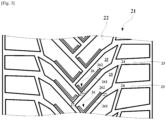
- FIG. 3 is schematic plan view of a tread according to a second embodiment of the present invention.
- the construction of this second embodiment is similar to that of the first embodiment other than the arrangement shown in Fig. 3 , thus description will be made referring to Fig. 3 .
- the tread 21 comprises a contact face 22 intended to come into contact with the ground during rolling, and at least one principal groove 23 of a depth D (not shown) extending in oblique to axial orientation from center to shoulder, and a plurality of sub grooves 24 of a depth Ds (not shown) extending in an orientation with an angle relative to an orientation the at least one principal groove 23 is extending.
- the at least one principal groove 23 and the plurality of sub grooves 24 delimiting a plurality of contact elements 25.
- a material constituting the plurality of contact elements 25 have a modulus G* at 60°C Mb and a glass transition temperature Tgb.
- the covering layer 26 consists of at least two layers, an outer covering layer 261 facing to outward of the contact element 25 and an inner covering layer 262 facing to inward of the contact element 25.
- a material constituting the outer covering layer 261 has a modulus G* at 60°C Mo and a glass transition temperature Tgo
- a material constituting the inner covering layer 262 has a modulus G* at 60°C Mi and a glass transition temperature Tgi.
- the covering layer 26 covers two lateral faces 27 of the contact element 25 placed at a center region of the tread 21.
- a width of the covering layer 26 is at least equal to 35% of a width of the contact element 25.
- the width of the covering layer 26 is at least equal to 35% of a width of the contact element 25, it is possible to improve performance on non-wintry surface at wide range of temperature while maintaining or even still improving performance on wintry surface.
- this width of the covering layer 26 is less than 35% of the width of the contact element 25, there is a risk that both the generation of higher mu via the outer covering layer 261 on non-wintry surface and of the edge effect on wintry surface and on non-wintry surface due to insufficient volume of the covering layer 26 to function.
- This width of the covering layer 26 is preferably at least equal to 50% of the width of the contact element 25, more preferably at least equal to 60% of the width of the contact element 25 and still more preferably at least equal to 80% of the width of the contact element 25.
- the covering layer 26 may be provided to only one of multiple side faces 27.
- the Examples were tires having the tread as described in the above the first embodiment with the contact elements provided with an incision opening to the contact face and extending fully in axial orientation.
- the covering layer was consisting of the outer covering layer and the inner covering layer.
- the Reference was a tire provided with one single covering layer. Internal construction of all the Examples, Comparative Example and the Reference was the same typical radial tire construction other than described above.
- Brand-new test tires were mounted onto all four wheel of a 2,000 cc front-wheel drive vehicle. On a straight path compacted snow surface, braking with ABS (Anti-lock Braking System) was applied at a speed of 50 km/h, distance until 5 km/h was measured.
- ABS Anti-lock Braking System
- results are shown in tables 1 and 2.
- results are represented by an index of 100 for Reference, higher the number indicates better the performance.
- Brand-new test tires were mounted onto all four wheel of a 2,000 cc front-wheel drive vehicle. On a straight path 1mm deep wet surface, braking with ABS (Anti-lock Braking System) was applied at a speed of 100 km/h, distance until 10 km/h was measured.
- ABS Anti-lock Braking System
Landscapes
- Engineering & Computer Science (AREA)
- Mechanical Engineering (AREA)
- Tires In General (AREA)
Description
- The present invention relates to a tread for a tire, in particular to a tread for a tire for providing improvement of performance on non-wintry surface while maintaining performance on wintry surface.
- In recent years, a tire so-called "all-season" tire which has capability to drive on wintry surface while maintaining high speed driving capability on non-wintry surface is beginning to popularize.
- Also to a tire so-called "studless" tire which is suitable for driving on ice covered and/or snow covered wintry surface, there is a desire to increase performance on non-wintry surface that is not covered by ice nor snow while still improving performance on wintry surface
- In order to increase performance on both wintry and non-wintry surface, introducing a hard layer onto a side face of a block is effective as the hard layer introduced onto the side face of the block increases efficiently so-called an edge pressure.
-
WO2013088570 discloses a tread for a pneumatic tire in which a reinforcing layer is provided on a side wall portion of a ground-contacting element of a tread of a tire for improving performance on wintry surface, and in a pneumatic tire having such a tread, the reinforcing layer has a mean thickness of less than 0.5 mm, is provided over an area at least equal to 50% of the side wall portion, and has a material modulus at least equal to 200 MPa -
JP1995-047814 -
JP2010-105509 - Attention is also drawn to the disclosure of
WO 2018/221630 A1 being relevant for the present invention. -
- [PTL 1]
WO2013088570 - [PTL 2]
JP1995-047814 - [PTL 3]
JP2010-105509 - However with the solutions disclosed in these documents, improvement of performance on non-wintry surface, especially wet performance is not satisfactory as a hard/a reinforcing layer providing a good edge effect has temperature dependency, in particular those providing an improvement of performance on wintry surface impacts negatively on wet performance at low surface temperature. Thus there is a desire to provide improvement of performance on non-wintry surface at wide range of temperature while maintaining or even still improving performance on wintry surface.
- Therefore, there is a need for a tread for a tire which provides improvement of performance on non-wintry surface at wide range of temperature while maintaining or even still improving performance on wintry surface.
- A "radial direction/orientation" is a direction/orientation perpendicular to axis of rotation of the tire. This direction/orientation corresponds to thickness orientation of the tread.
- An "axial direction/orientation" is a direction/orientation parallel to axis of rotation of the tire.
- A "circumferential direction/orientation" is a direction/orientation which is tangential to any circle centered on axis of rotation. This direction/orientation is perpendicular to both the axial direction/orientation and the radial direction/orientation.
- A "tire" means all types of elastic tire whether or not subjected to an internal pressure.
- A "tread" of a tire means a quantity of rubber material bounded by lateral surfaces and by two main surfaces one of which is intended to come into contact with ground when the tire is rolling.
- A "groove" is a space between two rubber faces/sidewalls which do not contact between themselves under usual rolling condition connected by another rubber face/ bottom. A groove has a width and a depth.
- An "incision", also referred to as a "sipe" is a narrow cutout formed toward radially inwardly from a surface of a tread made by, for example a thin blade having a shape like a knife blade. A width of the incision at the surface of the tread is narrower than a groove, for example less than or equal to 2.0mm. this incision may, different from the groove, be partly or completely closed when such the incision is in a contact patch and under usual rolling condition.
- A "contact patch" is a footprint of a tire mounted onto its standard rim as identified in tire standards such as ETRTO, JATMA or TRA, and inflated at its nominal pressure and under its nominal load. A "width TW" of a contact face is a maximum contact width of the contact patch along with an axis of rotation of the tire.
- A modulus G* is the dynamic shear complex modulus of the material at 60°C. The storage elastic modulus represented by G' and the loss elastic modulus represented by G", which are well known dynamic properties for one skilled in the art, are measured by means of a viscosity analyzer (microanalyzer: Metravib VB4000) using a test piece molded from the raw composition or a test piece which is combined with the composition after vulcanization. The test piece that is used is one that is described in Figure X2.1 (a circular method) of the standard ASTM D 5992-96 (version published September 2006, initially approved in 1996). The diameter'd' of the test piece is 10 mm (consequently the test piece has a circular cross section of 78.5 mm2), the thickness 'L' of each part of the rubber compound is 2 mm, and the ratio 'd/L' (described in paragraph X2.4 of the ASTM standard, in contrast to the ratio 'd/L' of 2 recommended in the standard ISO 2856) is 5. In the test, the response of a test piece comprising a vulcanized rubber composition subjected to a simple alternating sinusoidal shear load is measured at a frequency of 10 Hz. The maximum shear stress imposed during the test is 0.7 MPa. The test is conducted by varying the temperature from Tmin, which is a temperature lower than the glass transition temperature (Tg) of the rubber material, to a maximum temperature Tmax, in the vicinity of 100°C, at a rate of 1.5°C per minute. The test piece is stabilized for approximately 20 minutes at Tmin prior to the start of the test in order to obtain a satisfactory uniformity of temperature within the test piece. The results obtained are the storage elastic modulus (G') and the loss elastic modulus (G") at the prescribed temperature. The complex modulus G* is defined in terms of the absolute values of the storage elastic modulus and the loss elastic modulus using the following formula:

- It is thus an object of the invention to provide a tread for a tire which provides improvement of performance on non-wintry surface at wide range of temperature while maintaining or even still improving performance wintry surface.
- The present invention provides a tread for a tire having a contact face intended to come into contact with ground during rolling, the tread being provided with at least one principal groove of a depth Dp, and a plurality of sub grooves of a depth Ds extending in an orientation with an angle relative to an orientation the at least one principal groove being extending, the at least one principal groove and the plurality of sub grooves delimiting a plurality of contact elements, a material constituting the plurality of contact elements having a modulus G* at 60°C Mb and a glass transition temperature Tgb, at least one of a contact element among the plurality of contact elements being provided with a covering layer covering at least one of a lateral face of the contact element facing to circumferential orientation at least partly, the covering layer consists of at least two layers, an outer covering layer facing to outward of the contact element, a material constituting the outer covering layer has a modulus G* at 60°C Mo and a glass transition temperature Tgo, and an inner covering layer facing to inward of the contact element, a material constituting the inner covering layer has a modulus G* at 60°C Mi and a glass transition temperature Tgi and the modulus G* at 60°C Mb of the material constituting the contact element is higher than the modulus G* at 60°C Mi of the material constituting the inner covering layer, and the modulus G* at 60°C Mo of the material constituting the outer covering layer is higher than the modulus G* at 60°C Mb of the material constituting the contact element and/or the glass transition temperature Tgb of the material constituting the contact element is higher than the glass transition temperature Tgi of the material constituting the inner covering layer, and the glass transition temperature Tgo of the material constituting the outer covering layer is higher than the glass transition temperature Tgb of the material constituting the contact element.
- This arrangement provides an improvement of performance on non-wintry surface at wide range of temperature while maintaining or even still improving performance on wintry surface.
- Since at least one of the contact element is provided with the covering layer covering at least one of the lateral face of the contact element facing to circumferential orientation at least partly, the covering layer generates a good edge effect especially on wintry surface. Therefore it is possible to improve performance on wintry surface.
- Since the covering layer consists of at least two layers, the outer covering layer facing to outward of the contact element, the material constituting the outer covering layer has the modulus G* at 60°C Mo and the glass transition temperature Tgo, and the inner covering layer facing to inward of the contact element, the material constituting the inner covering layer has the modulus G* at 60°C Mi and the glass transition temperature Tgi, the covering layer can adapt wide range of temperature in particular on non-wintry surface by combining different modulus G* and different glass transition temperature. Therefore it is possible to improve performance on non-wintry surface at wide range of temperature.
- Since the modulus G* at 60°C Mb of the material constituting the contact element is higher than the modulus G* at 60°C Mi of the material constituting the inner covering layer, and the modulus G* at 60°C Mo of the material constituting the outer covering layer is higher than the modulus G* at 60°C Mb of the material constituting the contact element and/or the glass transition temperature Tgb of the material constituting the contact element is higher than the glass transition temperature Tgi of the material constituting the inner covering layer, and the glass transition temperature Tgo of the material constituting the outer covering layer is higher than the glass transition temperature Tgb of the material constituting the contact element, as the modulus G* at 60°C Mo of the material constituting the outer covering layer higher than the modulus G* at 60°C Mb of the material constituting the contact element enables to generate efficiently the edge effect especially on wintry surface and on non-wintry surface with relatively lower temperature, and the modulus G* at 60°C Mb of the material constituting the contact element higher than the modulus G* at 60°C Mi of the material constituting the inner covering layer supports to generate higher mu via the outer covering layer by generating a bending at the inner covering layer especially on non-wintry surface with relatively higher temperature thanks to the inner covering layer's relatively lower modulus G* at 60°C and/or as glass transition temperature Tgb of the material constituting the contact element higher than the glass transition temperature Tgi of the material constituting the inner covering layer supports to generate higher mu via the outer covering layer by generating a bending at the inner covering layer especially on non-wintry surface with relatively higher temperature thanks to the inner covering layer's relatively higher glass transition temperature, and the glass transition temperature Tgo of the material constituting the outer covering layer higher than the glass transition temperature Tgb of the material constituting the contact element enables to generate efficiently the edge effect especially on wintry surface and on non-wintry surface with relatively lower temperature. Therefore it is possible to improve performance on non-wintry surface at wide range of temperature while maintaining or even still improving performance on wintry surface.
- In another preferred embodiment, a thickness of the covering layer measured on a plane parallel to the contact face in an orientation perpendicular to an extending orientation of the principal groove or the sub groove in which the covering layer is facing is at most equal to 2.0 mm.
- If the thickness of the covering layer is more than 2.0 mm, there is a risk that a distribution of contact pressure in the contact face of the contact element becomes inappropriate leading degradation of performance on wintry surface especially on ice surface. By setting this thickness of the covering layer at most equal to 2.0 mm, it is possible to improve performance on non-wintry surface at wide range of temperature while maintaining or even still improving performance on wintry surface.
- This thickness of the covering layer measured on the plane parallel to the contact face in the orientation perpendicular to the extending orientation of the principal groove or the sub groove in which the covering layer is facing is preferably at most equal to 1.5 mm, more preferably at most equal to 1.0 mm.
- In another preferred embodiment, a thickness of the inner covering layer measured on a plane parallel to the contact face in an orientation perpendicular to an extending orientation of the principal groove or the sub groove in which the covering layer is facing is thicker than a thickness of the outer covering layer measured on the same plane.
- According to this arrangement, as the inner covering layer increases its capability to generate higher mu via the outer covering layer by generating a bending at the inner covering layer especially on non-wintry surface with relatively higher temperature, it is possible to improve performance on non-wintry surface at further wide range of temperature while maintaining or even still improving performance on wintry surface.
- In another preferred embodiment, a thickness of the inner covering layer measured on a plane parallel to the contact face in an orientation perpendicular to an extending orientation of the principal groove or the sub groove in which the covering layer is facing is thinner than a thickness of the outer covering layer measured on the same plane.
- According to this arrangement, as the outer covering layer generates more certainly the edge effect especially on wintry surface by increasing scraping power and contact surface, it is further possible to improve performance on wintry surface.
- In another preferred embodiment, a width of the covering layer is at least equal to 35% of a width of the contact element.
- If this width of the covering layer is less than 35% of the width of the contact element, there is a risk that both the generation of higher mu via the outer covering layer on non-wintry surface and of the edge effect on wintry surface and on non-wintry surface due to insufficient volume of the covering layer to function. By setting the width of the covering layer at least equal to 35% of the width of the contact element, it is possible to improve performance on non-wintry surface at wide range of temperature while maintaining or even still improving performance on wintry surface.
- This width of the covering layer is preferably at least equal to 50% of the width of the contact element, more preferably at least equal to 60% of the width of the contact element and still more preferably at least equal to 80% of the width of the contact element.
- According to the arrangements described above, it is possible to provide a tread for a tire which provides improvement of performance on non-wintry surface at wide range of temperature while maintaining or even still improving performance on wintry surface.
- Other characteristics and advantages of the invention arise from the description made hereafter in reference to the annexed drawings which show, as nonrestrictive examples, the embodiment of the invention.
- In these drawings:
- [
Fig. 1 ]
Fig. 1 is a schematic plan view of a tread according to a first embodiment of the present invention; - [
Fig. 2 ]
Fig. 2 is a schematic cross sectional view taken along line II-II inFig. 1 in different variations (a), (b) and (c); - [
Fig. 3 ]
Fig. 3 is a schematic plan view of a tread according to a second embodiment of the present invention; - Preferred embodiments of the present invention will be described below referring to the drawings.
- A
tread 1 for a tire according to a first embodiment of the present invention will be described referring toFigs. 1 and2 .Fig. 1 is a schematic plan view of a tread according to a first embodiment of the present invention.Fig. 2 is a schematic cross sectional view taken along line II-II inFig. 1 in different variations (a), (b) and (c). - The
tread 1 is a tread for a tire having dimension 225/45R17 and comprises acontact face 2 intended to come into contact with the ground during rolling, and at least one principal groove 3 of a depth Dp (shown inFig. 2 ) and a plurality ofsub grooves 4 of a depth Ds (shown inFig. 2 ) extending in an orientation with an angle relative to an orientation the at least one principal groove 3 being extending. Thetread 1 comprising a plurality ofcontact elements 5 delimited by the at least one principal groove 3 and the plurality ofsub grooves 4. A material constituting the plurality ofcontact elements 5 have a modulus G* at 60°C Mb and a glass transition temperature Tgb. In this first embodiment, thetread 1 comprises at least two principal grooves 3 extending in circumferential orientation that is top-bottom orientation inFig. 1 parallel to a center line indicated as line C-C', and the plurality ofsub grooves 4 are extending in axial orientation perpendicular to the circumferential orientation. - As shown in
Fig. 1 , the at least one of acontact element 5 among the plurality ofcontact elements 5 is provided with acovering layer 6 covering at least one of alateral face 7 of thecontact element 5 facing to circumferential orientation at least partly. In this first embodiment, thecovering layer 6 covers a full width of thecontact element 5. - As shown in
Figs. 1 and2 , thecovering layer 6 consists of at least two layers, anouter covering layer 61 facing to outward of thecontact element 5 and aninner covering layer 62 facing to inward of thecontact element 5. A material constituting theouter covering layer 61 has a modulus G* at 60°C Mo and a glass transition temperature Tgo, a material constituting theinner covering layer 62 has a modulus G* at 60°C Mi and a glass transition temperature Tgi. - The
contact element 5, theouter covering layer 61 and theinner covering layer 62 are configured as to have the modulus G* at 60°C Mb of the material constituting thecontact element 5 is higher than the modulus G* at 60°C Mi of the material constituting theinner covering layer 62, and the modulus G* at 60°C Mo of the material constituting theouter covering layer 61 is higher than the modulus G* at 60°C Mb of the material constituting thecontact element 5. - The
contact element 5, theouter covering layer 61 and theinner covering layer 62 are also configured as to have the glass transition temperature Tgb of the material constituting thecontact element 5 is higher than the glass transition temperature Tgi of the material constituting theinner covering layer 62, and the glass transition temperature Tgo of the material constituting theouter covering layer 61 is higher than the glass transition temperature Tgb of the material constituting thecontact element 5. - As shown in
Figs. 1 and2 , a thickness of thecovering layer 6 measured on a plane parallel to thecontact face 2 in an orientation perpendicular to an extending orientation of the principal groove 3 or thesub groove 4 in which thecovering layer 6 is facing is at most equal to 2.0 mm. - As shown in
Figs 1 and2 (a) , a thickness of theinner covering layer 62 measured on a plane parallel to thecontact face 2 in an orientation perpendicular to an extending orientation of the principal groove 3 or thesub groove 4 in which thecovering layer 6 is facing is equal to a thickness of theouter covering layer 61 measured on the same plane. As a variant, a thickness of theinner covering layer 62 measured on a plane parallel to thecontact face 2 in an orientation perpendicular to an extending orientation of the principal groove 3 or thesub groove 4 in which thecovering layer 6 is facing can be thinner than a thickness of theouter covering layer 61 measured on the same plane as shown inFig 2 (b) , or a thickness of theinner covering layer 62 measured on a plane parallel to thecontact face 2 in an orientation perpendicular to an extending orientation of the principal groove 3 or thesub groove 4 in which thecovering layer 6 is facing can be thicker than a thickness of theouter covering layer 61 measured on the same plane as shown inFig 2 (c) . - Since at least one of the
contact element 5 is provided with thecovering layer 6 covering at least one of thelateral face 7 of thecontact element 5 facing to circumferential orientation at least partly, thecovering layer 6 generates a good edge effect especially on wintry surface. Therefore it is possible to improve performance on wintry surface. - Since the
covering layer 6 consists of at least two layers, theouter covering layer 61 facing to outward of thecontact element 5, the material constituting theouter covering layer 61 has the modulus G* at 60°C Mo and the glass transition temperature Tgo, and theinner covering layer 62 facing to inward of thecontact element 5, the material constituting theinner covering layer 62 has the modulus G* at 60°C Mi and the glass transition temperature Tgi, thecovering layer 6 can adapt wide range of temperature in particular on non-wintry surface by combining different modulus G* and different glass transition temperature. Therefore it is possible to improve performance on non-wintry surface at wide range of temperature. - Since the modulus G* at 60°C Mb of the material constituting the
contact element 5 is higher than the modulus G* at 60°C Mi of the material constituting theinner covering layer 62, and the modulus G* at 60°C Mo of the material constituting theouter covering layer 61 is higher than the modulus G* at 60°C Mb of the material constituting thecontact element 5, it is possible to improve performance on non-wintry surface at wide range of temperature while maintaining or even still improving performance on wintry surface as the modulus G* at 60°C Mo of the material constituting theouter covering layer 61 higher than the modulus G* at 60°C Mb of the material constituting thecontact element 5 enables to generate efficiently the edge effect especially on wintry surface and on non-wintry surface with relatively lower temperature, and the modulus G* at 60°C Mb of the material constituting thecontact element 5 higher than the modulus G* at 60°C Mi of the material constituting theinner covering layer 62 supports to generate higher mu via theouter covering layer 61 by generating a bending at theinner covering layer 62 especially on non-wintry surface with relatively higher temperature thanks to the inner covering layer's relatively lower modulus G* at 60°C. - Since the glass transition temperature Tgb of the material constituting the
contact element 5 is higher than the glass transition temperature Tgi of the material constituting theinner covering layer 62, and the glass transition temperature Tgo of the material constituting theouter covering layer 61 is higher than the glass transition temperature Tgb of the material constituting thecontact element 5, it is possible to improve performance on non-wintry surface at wide range of temperature while maintaining or even still improving performance on wintry surface as the glass transition temperature Tgb of the material constituting thecontact element 5 higher than the glass transition temperature Tgi of the material constituting theinner covering layer 62 supports to generate higher mu via theouter covering layer 61 by generating a bending at theinner covering layer 62 especially on non-wintry surface with relatively higher temperature thanks to the inner covering layer's relatively higher glass transition temperature, and the glass transition temperature Tgo of the material constituting theouter covering layer 61 higher than the glass transition temperature Tgb of the material constituting thecontact element 5 enables to generate efficiently the edge effect especially on wintry surface and on non-wintry surface with relatively lower temperature. - Since the thickness of the
covering layer 6 measured on a plane parallel to thecontact face 2 in an orientation perpendicular to an extending orientation of the principal groove 3 or thesub groove 4 in which thecovering layer 6 is facing is at most equal to 2.0 mm, it is possible to improve performance on non-wintry surface at wide range of temperature while maintaining or even still improving performance on wintry surface. - If the thickness of the
covering layer 6 is more than 2.0 mm, there is a risk that a distribution of contact pressure in thecontact face 2 of thecontact element 5 becomes inappropriate leading degradation of performance on wintry surface especially on ice surface. - This thickness of the
covering layer 6 measured on the plane parallel to thecontact face 2 in the orientation perpendicular to the extending orientation of the principal groove 3 or thesub groove 4 in which thecovering layer 6 is facing is preferably at most equal to 1.5 mm, more preferably at most equal to 1.0 mm. - When designing the thickness of the
inner covering layer 62 measured on a plane parallel to thecontact face 2 in an orientation perpendicular to an extending orientation of the principal groove 3 or thesub groove 4 in which thecovering layer 6 is facing thicker than a thickness of theouter covering layer 61 measured on the same plane, it is possible to improve performance on non-wintry surface at further wide range of temperature while maintaining or even still improving performance on wintry surface as theinner covering layer 62 increases its capability to generate higher mu via theouter covering layer 61 by generating a bending at theinner covering layer 62 especially on non-wintry surface with relatively higher temperature. - When designing the thickness of the
inner covering layer 62 measured on a plane parallel to thecontact face 2 in an orientation perpendicular to an extending orientation of the principal groove 3 or thesub groove 4 in which thecovering layer 6 is facing thinner than a thickness of theouter covering layer 61 measured on the same plane, it is further possible to improve performance on wintry surface as theouter covering layer 61 generates more certainly the edge effect especially on wintry surface by increasing scraping power and contact surface. - The depth Dp of the principal groove 3 and the depth Ds of the
sub groove 4 may be the same as in this first embodiment, or may be different. - The
covering layer 6 may be provided as to cover other lateral faces 7 including those not facing to circumferential orientation. - The thickness of whole the
covering layer 6, theouter covering layer 61 or theinner covering layer 62 may vary in radial and/or axial orientation. - In radial orientation, the
outer covering layer 61 and theinner covering layer 62 may have different length. Preferably whole thecovering layer 6, theouter covering layer 61 or theinner covering layer 62 may be available until a level equivalent to a mean to indicate legal wear limit of thetread 1. - A
tread 21 according to a second embodiment of the present invention will be described referring toFig. 3. Fig. 3 is schematic plan view of a tread according to a second embodiment of the present invention. The construction of this second embodiment is similar to that of the first embodiment other than the arrangement shown inFig. 3 , thus description will be made referring toFig. 3 . - As shown in
Fig. 3 , thetread 21 comprises acontact face 22 intended to come into contact with the ground during rolling, and at least oneprincipal groove 23 of a depth D (not shown) extending in oblique to axial orientation from center to shoulder, and a plurality ofsub grooves 24 of a depth Ds (not shown) extending in an orientation with an angle relative to an orientation the at least oneprincipal groove 23 is extending. The at least oneprincipal groove 23 and the plurality ofsub grooves 24 delimiting a plurality ofcontact elements 25. A material constituting the plurality ofcontact elements 25 have a modulus G* at 60°C Mb and a glass transition temperature Tgb. - As shown in
Fig. 3 , at least one of acontact element 25 among the plurality ofcontact elements 25 being provided with acovering layer 26 covering at least one of alateral face 27 of thecontact element 25 facing to circumferential orientation at least partly, the coveringlayer 26 consists of at least two layers, anouter covering layer 261 facing to outward of thecontact element 25 and aninner covering layer 262 facing to inward of thecontact element 25. A material constituting theouter covering layer 261 has a modulus G* at 60°C Mo and a glass transition temperature Tgo, a material constituting theinner covering layer 262 has a modulus G* at 60°C Mi and a glass transition temperature Tgi. In this second embodiment, the coveringlayer 26 covers two lateral faces 27 of thecontact element 25 placed at a center region of thetread 21. - As shown in
Fig. 3 , a width of thecovering layer 26 is at least equal to 35% of a width of thecontact element 25. - Since the width of the
covering layer 26 is at least equal to 35% of a width of thecontact element 25, it is possible to improve performance on non-wintry surface at wide range of temperature while maintaining or even still improving performance on wintry surface. - If this width of the
covering layer 26 is less than 35% of the width of thecontact element 25, there is a risk that both the generation of higher mu via theouter covering layer 261 on non-wintry surface and of the edge effect on wintry surface and on non-wintry surface due to insufficient volume of thecovering layer 26 to function. - This width of the
covering layer 26 is preferably at least equal to 50% of the width of thecontact element 25, more preferably at least equal to 60% of the width of thecontact element 25 and still more preferably at least equal to 80% of the width of thecontact element 25. - Even multiple side faces 27 are facing to circumferential orientation, the covering
layer 26 may be provided to only one of multiple side faces 27. - The invention is not limited to the examples described and represented and various modifications can be made there without leaving its scope as defined by the claims.
- In order to confirm the effect of the present invention, two types of tires of Examples to which the present invention is applied and other types of tires of Reference and Comparative Example were prepared.
- The Examples were tires having the tread as described in the above the first embodiment with the contact elements provided with an incision opening to the contact face and extending fully in axial orientation. The covering layer was consisting of the outer covering layer and the inner covering layer. The Example 1 had been configured as to have the glass transition temperature Tgb of the material constituting the contact element higher than the glass transition temperature Tgi of the material constituting the inner covering layer (indicated as "=" for Tgb and "-" for Tgi), and the glass transition temperature Tgo of the material constituting the outer covering layer higher than the glass transition temperature Tgb of the material constituting the contact element (indicated as "=" for Tgb and "+" for Tgo). The Example 2 had been configured as to have the modulus G* at 60°C Mb of the material constituting the contact element higher than the modulus G* at 60°C Mi of the material constituting the inner covering layer (indicated as "=" for Mb and "-" for Mi), and the modulus G* at 60°C Mo of the material constituting the outer covering layer higher than the modulus G* at 60°C Mb of the material constituting the contact element (indicated as "=" for Mb and "+" for Mo). The Comparative Example was equivalent to the Example 2 but had been configured as to have the modulus G* at 60°C Mb of the material constituting the contact element higher than the modulus G* at 60°C Mi of the material constituting the inner covering layer (indicated as "=" for Mb and "-" for Mi), and the modulus G* at 60°C Mo of the material constituting the outer covering layer lower than the modulus G* at 60°C Mb of the material constituting the contact element (indicated as "=" for Mb and "--" for Mo). The Reference was a tire provided with one single covering layer. Internal construction of all the Examples, Comparative Example and the Reference was the same typical radial tire construction other than described above.
- Brand-new test tires were mounted onto all four wheel of a 2,000 cc front-wheel drive vehicle. On a straight path compacted snow surface, braking with ABS (Anti-lock Braking System) was applied at a speed of 50 km/h, distance until 5 km/h was measured.
- The results are shown in tables 1 and 2. In these tables 1 and 2, results are represented by an index of 100 for Reference, higher the number indicates better the performance.
- Brand-new test tires were mounted onto all four wheel of a 2,000 cc front-wheel drive vehicle. On a straight path 1mm deep wet surface, braking with ABS (Anti-lock Braking System) was applied at a speed of 100 km/h, distance until 10 km/h was measured.
- The results are also shown in tables 1 and 2. In these tables 1 and 2, results are represented by an index of 100 for Reference, higher the number indicates better the performance.
[Table 1] Example 1 Comparative Example Reference modulus G* at 60°C Mb = = = modulus G* at 60°C Mi - - = modulus G* at 60°C Mo + -- + Snow braking (index) 103 100 Wet braking at 8°C (index) 108 97 100 Wet braking at 15°C (index) 106 96 100 [Table 2] Example 2 Reference Glass transition temperature Tgb = = Glass transition temperature Tgi - = Glass transition temperature Tgo + + Snow braking (index) 100 100 Wet braking at 8°C (index) 104 1 00 Wet braking at 15°C (index) 103 100 - As seen from tables 1 and 2, the Examples show improvement of performance on non-wintry surface at wide range of temperature while maintaining or even still improving performance on wintry surface, which cannot be achieved by treads disclosed in prior arts.
-
- 1, 21
- tread
- 2, 22
- contact face
- 3, 23
- principal groove
- 4, 24
- sub groove
- 5, 25
- contact element
- 6, 26
- covering layer
- 61, 261
- outer covering layer
- 62, 262
- inner covering layer
- 7, 27
- lateral face
Claims (6)
- A tread (1) for a tire having a contact face (2) intended to come into contact with ground during rolling, the tread (1) being provided with at least one principal groove (3) of a depth Dp, and a plurality of sub grooves (4) of a depth Ds extending in an orientation with an angle relative to an orientation the at least one principal groove (3) being extending, the at least one principal groove (3) and the plurality of sub grooves (4) delimiting a plurality of contact elements (5), a material constituting the plurality of contact elements (5) having a modulus G* at 60°C Mb and a glass transition temperature Tgb,at least one of a contact element (5) among the plurality of contact elements (5) being provided with a covering layer (6) covering at least one of a lateral face (7) of the contact element (5) facing to circumferential orientation at least partly,the covering layer (6) consisting of at least two layers, an outer covering layer (61) facing to outward of the contact element (5), a material constituting the outer covering layer (61) has a modulus G* at 60°C Mo and a glass transition temperature Tgo, and an inner covering layer (62) facing to inward of the contact element (5), a material constituting the inner covering layer (62) has a modulus G* at 60°C Mi and a glass transition temperature Tgi, the tread being characterized in that the modulus G* at 60°C Mb of the material constituting the contact element (5) is higher than the modulus G* at 60°C Mi of the material constituting the inner covering layer (62), and wherein the modulus G* at 60°C Mo of the material constituting the outer covering layer (61) is higher than the modulus G* at 60°C Mb of the material constituting the contact element (5) and/or the glass transition temperature Tgb of the material constituting the contact element (5) is higher than the glass transition temperature Tgi of the material constituting the inner covering layer (62), and wherein the glass transition temperature Tgo of the material constituting the outer covering layer (61) is higher than the glass transition temperature Tgb of the material constituting the contact element (5), the modulus G* Mb, Mo and Mi being measured according to ASTM D 5992-96 standard by subjecting the material to a simple alternating sinusoidal shear load at a frequency of 10 Hz under a maximum shear stress imposed of 0.7 MPa.
- The tread (1) according to Claim 1, wherein a thickness of the covering layer (6) measured on a plane parallel to the contact face (2) in an orientation perpendicular to an extending orientation of the principal groove (3) or the sub groove (4) in which the covering layer (6) is facing is at most equal to 2.0 mm.
- The tread (1) according to Claim 1 or Claim 2, wherein a thickness of the inner covering layer (62) measured on a plane parallel to the contact face (2) in an orientation perpendicular to an extending orientation of the principal groove (3) or the sub groove (4) in which the covering layer (6) is facing is thicker than a thickness of the outer covering layer (61) measured on the same plane.
- The tread (1) according to Claim 1 or Claim 2, wherein a thickness of the inner covering layer (62) measured on a plane parallel to the contact face (2) in an orientation perpendicular to an extending orientation of the principal groove (3) or the sub groove (4) in which the covering layer (6) is facing is thinner than a thickness of the outer covering layer (61) measured on the same plane.
- The tread (1) according to any one of the Claims 1 to 4, wherein a width of the covering layer (6) is at least equal to 35% of a width of the contact element (5).
- A tire having a tread according to any one of the Claims 1 to 5.
Applications Claiming Priority (1)
| Application Number | Priority Date | Filing Date | Title |
|---|---|---|---|
| PCT/JP2020/047832 WO2022137317A1 (en) | 2020-12-22 | 2020-12-22 | A tire tread |
Publications (2)
| Publication Number | Publication Date |
|---|---|
| EP4267412A1 EP4267412A1 (en) | 2023-11-01 |
| EP4267412B1 true EP4267412B1 (en) | 2024-07-31 |
Family
ID=74186786
Family Applications (1)
| Application Number | Title | Priority Date | Filing Date |
|---|---|---|---|
| EP20842329.3A Active EP4267412B1 (en) | 2020-12-22 | 2020-12-22 | A tire tread |
Country Status (6)
| Country | Link |
|---|---|
| EP (1) | EP4267412B1 (en) |
| JP (1) | JP7676550B2 (en) |
| CN (1) | CN116601017B (en) |
| CA (1) | CA3199203A1 (en) |
| FI (1) | FI4267412T3 (en) |
| WO (1) | WO2022137317A1 (en) |
Family Cites Families (19)
| Publication number | Priority date | Publication date | Assignee | Title |
|---|---|---|---|---|
| JPS60124507A (en) * | 1983-12-09 | 1985-07-03 | Yokohama Rubber Co Ltd:The | Pneumatic tire |
| JP3373900B2 (en) * | 1993-08-03 | 2003-02-04 | 住友ゴム工業株式会社 | Pneumatic tire |
| EP1499507A1 (en) * | 2002-04-19 | 2005-01-26 | Société de Technologie Michelin | Tread with tread design elements which are formed from at least two mixtures of rubber |
| JP4318690B2 (en) | 2005-12-22 | 2009-08-26 | 住友ゴム工業株式会社 | Pneumatic tire for running on rough terrain |
| JP2010105509A (en) * | 2008-10-29 | 2010-05-13 | Yokohama Rubber Co Ltd:The | Pneumatic tire |
| BRPI0823387B1 (en) * | 2008-12-23 | 2020-10-13 | Pirelli Tyre S.P.A | vehicle wheel tire |
| RU2569147C1 (en) * | 2011-12-16 | 2015-11-20 | Компани Женераль Дез Этаблиссман Мишлен | Pneumatic tire tread |
| FR2984227B1 (en) * | 2011-12-16 | 2015-04-03 | Michelin Soc Tech | TREAD BAND HAVING SCULPTURE ELEMENTS COVERED WITH THERMOPLASTIC MATERIAL. |
| FR2984226B1 (en) | 2011-12-16 | 2014-06-20 | Michelin Soc Tech | METHOD FOR MANUFACTURING A TIRE TREAD FOR TIRES |
| FR2984228B1 (en) * | 2011-12-16 | 2016-09-30 | Soc De Tech Michelin | TREAD BAND HAVING SCULPTURE ELEMENTS COVERED WITH AN IMPREGNATED FIBER ASSEMBLY |
| FR2999118B1 (en) * | 2012-12-10 | 2015-01-16 | Michelin & Cie | PNEUMATIC COMPRISING A TREAD TAPE CONSISTING OF SEVERAL ELASTOMERIC MIXTURES |
| WO2014104339A1 (en) * | 2012-12-28 | 2014-07-03 | コンパニー ゼネラール デ エタブリッスマン ミシュラン | Tread for pneumatic tire and pneumatic tire having said tread |
| JP6214368B2 (en) | 2013-12-05 | 2017-10-18 | 住友ゴム工業株式会社 | Pneumatic tire |
| FR3014750B1 (en) * | 2013-12-17 | 2017-02-24 | Michelin & Cie | Tread comprising pavers and thin grooves on the paving stones |
| CN109789735B (en) * | 2016-09-27 | 2021-02-02 | 米其林企业总公司 | Tire tread and tire with the same |
| WO2018221630A1 (en) * | 2017-05-31 | 2018-12-06 | Compagnie Generale Des Etablissements Michelin | A tire comprising a tread |
| FR3068916A1 (en) * | 2017-07-17 | 2019-01-18 | Compagnie Generale Des Etablissements Michelin | PNEUMATIC TIRE SUB-LAYER WITH FLAT ROTATING BEARING SUB-LAYER AND HIGH MODULAR RUBBER REINFORCING ELEMENTS INTEGRATED WITH THE TREAD |
| FR3069485A1 (en) * | 2017-07-25 | 2019-02-01 | Compagnie Generale Des Etablissements Michelin | PNEUMATIC TIRE WITH TREAD COMPRISING AN EVOLVING SCULPTURE WITH INCISIONS |
| WO2020090884A1 (en) * | 2018-10-30 | 2020-05-07 | Compagnie Generale Des Etablissements Michelin | A tire tread for improved snow performance |
-
2020
- 2020-12-22 WO PCT/JP2020/047832 patent/WO2022137317A1/en not_active Ceased
- 2020-12-22 CN CN202080108066.6A patent/CN116601017B/en active Active
- 2020-12-22 CA CA3199203A patent/CA3199203A1/en active Pending
- 2020-12-22 FI FIEP20842329.3T patent/FI4267412T3/en active
- 2020-12-22 JP JP2023537615A patent/JP7676550B2/en active Active
- 2020-12-22 EP EP20842329.3A patent/EP4267412B1/en active Active
Also Published As
| Publication number | Publication date |
|---|---|
| CN116601017B (en) | 2024-10-25 |
| FI4267412T3 (en) | 2024-10-31 |
| WO2022137317A1 (en) | 2022-06-30 |
| JP7676550B2 (en) | 2025-05-14 |
| JP2024502560A (en) | 2024-01-22 |
| EP4267412A1 (en) | 2023-11-01 |
| CN116601017A (en) | 2023-08-15 |
| CA3199203A1 (en) | 2022-06-30 |
Similar Documents
| Publication | Publication Date | Title |
|---|---|---|
| EP1403098B1 (en) | Off the road tire | |
| EP2439083B1 (en) | Pneumatic tire | |
| EP3532314B1 (en) | A tread made from multi compounds | |
| EP2792504B1 (en) | Tread for pneumatic tire | |
| EP3647078A1 (en) | Tyre | |
| EP3437898B1 (en) | Tire | |
| EP3828011A1 (en) | Tyre tread | |
| EP4267412B1 (en) | A tire tread | |
| WO2020090884A1 (en) | A tire tread for improved snow performance | |
| EP3814151B1 (en) | A tread for improved snow performance | |
| EP3856536B1 (en) | A tire for multi performance | |
| EP4267411B1 (en) | A tire tread for long lasting performance | |
| EP4081412B1 (en) | A noise improving tread | |
| EP4065388B1 (en) | A tread for improving wintry performance | |
| EP4065389B1 (en) | A tread for improving snow performance | |
| JPH01297302A (en) | Pneumatic tyre | |
| EP4108475A1 (en) | Tyre | |
| WO2021130879A1 (en) | A tread for balanced performance |
Legal Events
| Date | Code | Title | Description |
|---|---|---|---|
| STAA | Information on the status of an ep patent application or granted ep patent |
Free format text: STATUS: UNKNOWN |
|
| STAA | Information on the status of an ep patent application or granted ep patent |
Free format text: STATUS: THE INTERNATIONAL PUBLICATION HAS BEEN MADE |
|
| PUAI | Public reference made under article 153(3) epc to a published international application that has entered the european phase |
Free format text: ORIGINAL CODE: 0009012 |
|
| STAA | Information on the status of an ep patent application or granted ep patent |
Free format text: STATUS: REQUEST FOR EXAMINATION WAS MADE |
|
| 17P | Request for examination filed |
Effective date: 20230724 |
|
| AK | Designated contracting states |
Kind code of ref document: A1 Designated state(s): AL AT BE BG CH CY CZ DE DK EE ES FI FR GB GR HR HU IE IS IT LI LT LU LV MC MK MT NL NO PL PT RO RS SE SI SK SM TR |
|
| DAV | Request for validation of the european patent (deleted) | ||
| DAX | Request for extension of the european patent (deleted) | ||
| GRAP | Despatch of communication of intention to grant a patent |
Free format text: ORIGINAL CODE: EPIDOSNIGR1 |
|
| STAA | Information on the status of an ep patent application or granted ep patent |
Free format text: STATUS: GRANT OF PATENT IS INTENDED |
|
| INTG | Intention to grant announced |
Effective date: 20240422 |
|
| GRAS | Grant fee paid |
Free format text: ORIGINAL CODE: EPIDOSNIGR3 |
|
| GRAA | (expected) grant |
Free format text: ORIGINAL CODE: 0009210 |
|
| STAA | Information on the status of an ep patent application or granted ep patent |
Free format text: STATUS: THE PATENT HAS BEEN GRANTED |
|
| AK | Designated contracting states |
Kind code of ref document: B1 Designated state(s): AL AT BE BG CH CY CZ DE DK EE ES FI FR GB GR HR HU IE IS IT LI LT LU LV MC MK MT NL NO PL PT RO RS SE SI SK SM TR |
|
| REG | Reference to a national code |
Ref country code: CH Ref legal event code: EP Ref country code: GB Ref legal event code: FG4D |
|
| REG | Reference to a national code |
Ref country code: DE Ref legal event code: R096 Ref document number: 602020035017 Country of ref document: DE |
|
| REG | Reference to a national code |
Ref country code: IE Ref legal event code: FG4D |
|
| REG | Reference to a national code |
Ref country code: FI Ref legal event code: FGE |
|
| REG | Reference to a national code |
Ref country code: SE Ref legal event code: TRGR |
|
| REG | Reference to a national code |
Ref country code: LT Ref legal event code: MG9D |
|
| REG | Reference to a national code |
Ref country code: NL Ref legal event code: MP Effective date: 20240731 |
|
| PG25 | Lapsed in a contracting state [announced via postgrant information from national office to epo] |
Ref country code: PT Free format text: LAPSE BECAUSE OF FAILURE TO SUBMIT A TRANSLATION OF THE DESCRIPTION OR TO PAY THE FEE WITHIN THE PRESCRIBED TIME-LIMIT Effective date: 20241202 |
|
| REG | Reference to a national code |
Ref country code: AT Ref legal event code: MK05 Ref document number: 1708143 Country of ref document: AT Kind code of ref document: T Effective date: 20240731 |
|
| PG25 | Lapsed in a contracting state [announced via postgrant information from national office to epo] |
Ref country code: PT Free format text: LAPSE BECAUSE OF FAILURE TO SUBMIT A TRANSLATION OF THE DESCRIPTION OR TO PAY THE FEE WITHIN THE PRESCRIBED TIME-LIMIT Effective date: 20241202 |
|
| PG25 | Lapsed in a contracting state [announced via postgrant information from national office to epo] |
Ref country code: NO Free format text: LAPSE BECAUSE OF FAILURE TO SUBMIT A TRANSLATION OF THE DESCRIPTION OR TO PAY THE FEE WITHIN THE PRESCRIBED TIME-LIMIT Effective date: 20241031 |
|
| PG25 | Lapsed in a contracting state [announced via postgrant information from national office to epo] |
Ref country code: NL Free format text: LAPSE BECAUSE OF FAILURE TO SUBMIT A TRANSLATION OF THE DESCRIPTION OR TO PAY THE FEE WITHIN THE PRESCRIBED TIME-LIMIT Effective date: 20240731 Ref country code: PL Free format text: LAPSE BECAUSE OF FAILURE TO SUBMIT A TRANSLATION OF THE DESCRIPTION OR TO PAY THE FEE WITHIN THE PRESCRIBED TIME-LIMIT Effective date: 20240731 Ref country code: GR Free format text: LAPSE BECAUSE OF FAILURE TO SUBMIT A TRANSLATION OF THE DESCRIPTION OR TO PAY THE FEE WITHIN THE PRESCRIBED TIME-LIMIT Effective date: 20241101 |
|
| PG25 | Lapsed in a contracting state [announced via postgrant information from national office to epo] |
Ref country code: BG Free format text: LAPSE BECAUSE OF FAILURE TO SUBMIT A TRANSLATION OF THE DESCRIPTION OR TO PAY THE FEE WITHIN THE PRESCRIBED TIME-LIMIT Effective date: 20240731 |
|
| PG25 | Lapsed in a contracting state [announced via postgrant information from national office to epo] |
Ref country code: LV Free format text: LAPSE BECAUSE OF FAILURE TO SUBMIT A TRANSLATION OF THE DESCRIPTION OR TO PAY THE FEE WITHIN THE PRESCRIBED TIME-LIMIT Effective date: 20240731 |
|
| PG25 | Lapsed in a contracting state [announced via postgrant information from national office to epo] |
Ref country code: AT Free format text: LAPSE BECAUSE OF FAILURE TO SUBMIT A TRANSLATION OF THE DESCRIPTION OR TO PAY THE FEE WITHIN THE PRESCRIBED TIME-LIMIT Effective date: 20240731 Ref country code: IS Free format text: LAPSE BECAUSE OF FAILURE TO SUBMIT A TRANSLATION OF THE DESCRIPTION OR TO PAY THE FEE WITHIN THE PRESCRIBED TIME-LIMIT Effective date: 20241130 |
|
| PG25 | Lapsed in a contracting state [announced via postgrant information from national office to epo] |
Ref country code: HR Free format text: LAPSE BECAUSE OF FAILURE TO SUBMIT A TRANSLATION OF THE DESCRIPTION OR TO PAY THE FEE WITHIN THE PRESCRIBED TIME-LIMIT Effective date: 20240731 |
|
| PG25 | Lapsed in a contracting state [announced via postgrant information from national office to epo] |
Ref country code: RS Free format text: LAPSE BECAUSE OF FAILURE TO SUBMIT A TRANSLATION OF THE DESCRIPTION OR TO PAY THE FEE WITHIN THE PRESCRIBED TIME-LIMIT Effective date: 20241031 Ref country code: ES Free format text: LAPSE BECAUSE OF FAILURE TO SUBMIT A TRANSLATION OF THE DESCRIPTION OR TO PAY THE FEE WITHIN THE PRESCRIBED TIME-LIMIT Effective date: 20240731 |
|
| PG25 | Lapsed in a contracting state [announced via postgrant information from national office to epo] |
Ref country code: RS Free format text: LAPSE BECAUSE OF FAILURE TO SUBMIT A TRANSLATION OF THE DESCRIPTION OR TO PAY THE FEE WITHIN THE PRESCRIBED TIME-LIMIT Effective date: 20241031 Ref country code: PL Free format text: LAPSE BECAUSE OF FAILURE TO SUBMIT A TRANSLATION OF THE DESCRIPTION OR TO PAY THE FEE WITHIN THE PRESCRIBED TIME-LIMIT Effective date: 20240731 Ref country code: NO Free format text: LAPSE BECAUSE OF FAILURE TO SUBMIT A TRANSLATION OF THE DESCRIPTION OR TO PAY THE FEE WITHIN THE PRESCRIBED TIME-LIMIT Effective date: 20241031 Ref country code: NL Free format text: LAPSE BECAUSE OF FAILURE TO SUBMIT A TRANSLATION OF THE DESCRIPTION OR TO PAY THE FEE WITHIN THE PRESCRIBED TIME-LIMIT Effective date: 20240731 Ref country code: LV Free format text: LAPSE BECAUSE OF FAILURE TO SUBMIT A TRANSLATION OF THE DESCRIPTION OR TO PAY THE FEE WITHIN THE PRESCRIBED TIME-LIMIT Effective date: 20240731 Ref country code: IS Free format text: LAPSE BECAUSE OF FAILURE TO SUBMIT A TRANSLATION OF THE DESCRIPTION OR TO PAY THE FEE WITHIN THE PRESCRIBED TIME-LIMIT Effective date: 20241130 Ref country code: HR Free format text: LAPSE BECAUSE OF FAILURE TO SUBMIT A TRANSLATION OF THE DESCRIPTION OR TO PAY THE FEE WITHIN THE PRESCRIBED TIME-LIMIT Effective date: 20240731 Ref country code: GR Free format text: LAPSE BECAUSE OF FAILURE TO SUBMIT A TRANSLATION OF THE DESCRIPTION OR TO PAY THE FEE WITHIN THE PRESCRIBED TIME-LIMIT Effective date: 20241101 Ref country code: ES Free format text: LAPSE BECAUSE OF FAILURE TO SUBMIT A TRANSLATION OF THE DESCRIPTION OR TO PAY THE FEE WITHIN THE PRESCRIBED TIME-LIMIT Effective date: 20240731 Ref country code: BG Free format text: LAPSE BECAUSE OF FAILURE TO SUBMIT A TRANSLATION OF THE DESCRIPTION OR TO PAY THE FEE WITHIN THE PRESCRIBED TIME-LIMIT Effective date: 20240731 Ref country code: AT Free format text: LAPSE BECAUSE OF FAILURE TO SUBMIT A TRANSLATION OF THE DESCRIPTION OR TO PAY THE FEE WITHIN THE PRESCRIBED TIME-LIMIT Effective date: 20240731 |
|
| PG25 | Lapsed in a contracting state [announced via postgrant information from national office to epo] |
Ref country code: SM Free format text: LAPSE BECAUSE OF FAILURE TO SUBMIT A TRANSLATION OF THE DESCRIPTION OR TO PAY THE FEE WITHIN THE PRESCRIBED TIME-LIMIT Effective date: 20240731 Ref country code: DK Free format text: LAPSE BECAUSE OF FAILURE TO SUBMIT A TRANSLATION OF THE DESCRIPTION OR TO PAY THE FEE WITHIN THE PRESCRIBED TIME-LIMIT Effective date: 20240731 Ref country code: RO Free format text: LAPSE BECAUSE OF FAILURE TO SUBMIT A TRANSLATION OF THE DESCRIPTION OR TO PAY THE FEE WITHIN THE PRESCRIBED TIME-LIMIT Effective date: 20240731 |
|
| PG25 | Lapsed in a contracting state [announced via postgrant information from national office to epo] |
Ref country code: EE Free format text: LAPSE BECAUSE OF FAILURE TO SUBMIT A TRANSLATION OF THE DESCRIPTION OR TO PAY THE FEE WITHIN THE PRESCRIBED TIME-LIMIT Effective date: 20240731 |
|
| PG25 | Lapsed in a contracting state [announced via postgrant information from national office to epo] |
Ref country code: CZ Free format text: LAPSE BECAUSE OF FAILURE TO SUBMIT A TRANSLATION OF THE DESCRIPTION OR TO PAY THE FEE WITHIN THE PRESCRIBED TIME-LIMIT Effective date: 20240731 |
|
| PG25 | Lapsed in a contracting state [announced via postgrant information from national office to epo] |
Ref country code: SK Free format text: LAPSE BECAUSE OF FAILURE TO SUBMIT A TRANSLATION OF THE DESCRIPTION OR TO PAY THE FEE WITHIN THE PRESCRIBED TIME-LIMIT Effective date: 20240731 Ref country code: IT Free format text: LAPSE BECAUSE OF FAILURE TO SUBMIT A TRANSLATION OF THE DESCRIPTION OR TO PAY THE FEE WITHIN THE PRESCRIBED TIME-LIMIT Effective date: 20240731 |
|
| REG | Reference to a national code |
Ref country code: DE Ref legal event code: R097 Ref document number: 602020035017 Country of ref document: DE |
|
| PLBE | No opposition filed within time limit |
Free format text: ORIGINAL CODE: 0009261 |
|
| STAA | Information on the status of an ep patent application or granted ep patent |
Free format text: STATUS: NO OPPOSITION FILED WITHIN TIME LIMIT |
|
| PG25 | Lapsed in a contracting state [announced via postgrant information from national office to epo] |
Ref country code: MC Free format text: LAPSE BECAUSE OF FAILURE TO SUBMIT A TRANSLATION OF THE DESCRIPTION OR TO PAY THE FEE WITHIN THE PRESCRIBED TIME-LIMIT Effective date: 20240731 |
|
| 26N | No opposition filed |
Effective date: 20250501 |
|
| REG | Reference to a national code |
Ref country code: CH Ref legal event code: PL |
|
| PG25 | Lapsed in a contracting state [announced via postgrant information from national office to epo] |
Ref country code: LU Free format text: LAPSE BECAUSE OF NON-PAYMENT OF DUE FEES Effective date: 20241222 |
|
| GBPC | Gb: european patent ceased through non-payment of renewal fee |
Effective date: 20241222 |
|
| REG | Reference to a national code |
Ref country code: BE Ref legal event code: MM Effective date: 20241231 |
|
| PG25 | Lapsed in a contracting state [announced via postgrant information from national office to epo] |
Ref country code: BE Free format text: LAPSE BECAUSE OF NON-PAYMENT OF DUE FEES Effective date: 20241231 Ref country code: GB Free format text: LAPSE BECAUSE OF NON-PAYMENT OF DUE FEES Effective date: 20241222 |
|
| PG25 | Lapsed in a contracting state [announced via postgrant information from national office to epo] |
Ref country code: CH Free format text: LAPSE BECAUSE OF NON-PAYMENT OF DUE FEES Effective date: 20241231 |
|
| PG25 | Lapsed in a contracting state [announced via postgrant information from national office to epo] |
Ref country code: IE Free format text: LAPSE BECAUSE OF NON-PAYMENT OF DUE FEES Effective date: 20241222 |
|
| PGFP | Annual fee paid to national office [announced via postgrant information from national office to epo] |
Ref country code: DE Payment date: 20251211 Year of fee payment: 6 |
|
| PGFP | Annual fee paid to national office [announced via postgrant information from national office to epo] |
Ref country code: FI Payment date: 20251224 Year of fee payment: 6 |
|
| PGFP | Annual fee paid to national office [announced via postgrant information from national office to epo] |
Ref country code: FR Payment date: 20251229 Year of fee payment: 6 |
|
| PGFP | Annual fee paid to national office [announced via postgrant information from national office to epo] |
Ref country code: SE Payment date: 20251219 Year of fee payment: 6 |