EP4267058B1 - Prozessorgesteuerte pumpe in einer spülleitung einer phakoemulsifikationssonde - Google Patents
Prozessorgesteuerte pumpe in einer spülleitung einer phakoemulsifikationssonde Download PDFInfo
- Publication number
- EP4267058B1 EP4267058B1 EP21827670.7A EP21827670A EP4267058B1 EP 4267058 B1 EP4267058 B1 EP 4267058B1 EP 21827670 A EP21827670 A EP 21827670A EP 4267058 B1 EP4267058 B1 EP 4267058B1
- Authority
- EP
- European Patent Office
- Prior art keywords
- irrigation
- aspiration
- processor
- pump
- line
- Prior art date
- Legal status (The legal status is an assumption and is not a legal conclusion. Google has not performed a legal analysis and makes no representation as to the accuracy of the status listed.)
- Active
Links
Images

Classifications
-
- A—HUMAN NECESSITIES
- A61—MEDICAL OR VETERINARY SCIENCE; HYGIENE
- A61F—FILTERS IMPLANTABLE INTO BLOOD VESSELS; PROSTHESES; DEVICES PROVIDING PATENCY TO, OR PREVENTING COLLAPSING OF, TUBULAR STRUCTURES OF THE BODY, e.g. STENTS; ORTHOPAEDIC, NURSING OR CONTRACEPTIVE DEVICES; FOMENTATION; TREATMENT OR PROTECTION OF EYES OR EARS; BANDAGES, DRESSINGS OR ABSORBENT PADS; FIRST-AID KITS
- A61F9/00—Methods or devices for treatment of the eyes; Devices for putting in contact-lenses; Devices to correct squinting; Apparatus to guide the blind; Protective devices for the eyes, carried on the body or in the hand
- A61F9/007—Methods or devices for eye surgery
- A61F9/00736—Instruments for removal of intra-ocular material or intra-ocular injection, e.g. cataract instruments
- A61F9/00745—Instruments for removal of intra-ocular material or intra-ocular injection, e.g. cataract instruments using mechanical vibrations, e.g. ultrasonic
-
- A—HUMAN NECESSITIES
- A61—MEDICAL OR VETERINARY SCIENCE; HYGIENE
- A61M—DEVICES FOR INTRODUCING MEDIA INTO, OR ONTO, THE BODY; DEVICES FOR TRANSDUCING BODY MEDIA OR FOR TAKING MEDIA FROM THE BODY; DEVICES FOR PRODUCING OR ENDING SLEEP OR STUPOR
- A61M1/00—Suction or pumping devices for medical purposes; Devices for carrying-off, for treatment of, or for carrying-over, body-liquids; Drainage systems
- A61M1/71—Suction drainage systems
- A61M1/74—Suction control
- A61M1/743—Suction control by changing the cross-section of the line, e.g. flow regulating valves
-
- A—HUMAN NECESSITIES
- A61—MEDICAL OR VETERINARY SCIENCE; HYGIENE
- A61M—DEVICES FOR INTRODUCING MEDIA INTO, OR ONTO, THE BODY; DEVICES FOR TRANSDUCING BODY MEDIA OR FOR TAKING MEDIA FROM THE BODY; DEVICES FOR PRODUCING OR ENDING SLEEP OR STUPOR
- A61M2205/00—General characteristics of the apparatus
- A61M2205/50—General characteristics of the apparatus with microprocessors or computers
-
- A—HUMAN NECESSITIES
- A61—MEDICAL OR VETERINARY SCIENCE; HYGIENE
- A61M—DEVICES FOR INTRODUCING MEDIA INTO, OR ONTO, THE BODY; DEVICES FOR TRANSDUCING BODY MEDIA OR FOR TAKING MEDIA FROM THE BODY; DEVICES FOR PRODUCING OR ENDING SLEEP OR STUPOR
- A61M2210/00—Anatomical parts of the body
- A61M2210/06—Head
- A61M2210/0612—Eyes
Definitions
- the present invention relates generally to phacoemulsification, and specifically to irrigation in phacoemulsification systems.
- a cataract is a clouding and hardening of the eye's natural lens, a structure which is positioned behind the cornea, iris and pupil.
- the lens is mostly made up of water and protein and as people age these proteins change and may begin to clump together obscuring portions of the lens.
- a physician may recommend phacoemulsification cataract surgery.
- the surgeon makes a small incision in the sclera or cornea of the eye.
- a portion of the anterior surface of the lens capsule is removed to gain access to the cataract.
- the surgeon uses a phacoemulsification probe, which has an ultrasonic handpiece with a needle.
- the tip of the needle vibrates at ultrasonic frequency to sculpt and emulsify the cataract while a pump aspirates particles and fluid from the eye through the tip. Aspirated fluids are replaced with irrigation of a balanced salt solution to maintain the anterior chamber of the eye. After removing the cataract with phacoemulsification, the softer outer lens cortex is removed with suction. An intraocular lens (IOL) is then introduced into the empty lens capsule restoring the patient's vision.
- IOL intraocular lens
- U.S. Patent 5,160,317 describes a method and apparatus for operating on the human eye that detects changes in load on the transducer and controls aspiration based on the load changes. A change from a lower load to a higher load indicates that harder tissue is being encountered and accordingly causes aspiration amount to increase. Conversely, a change from a higher load to a lower load indicates that aspiration amount should be quickly decreased since the tissue which is being encountered is softer.
- U.S. Patent 10,052,227 describes a surgical apparatus configurable for removal of the cortex and the polishing of the capsule during cataract extraction surgery.
- a microprocessor-controlled pump and valve are used to calculate the specific fluid exchange such that the velocity and volume of the fluids extracted and introduced are relatively matched.
- the microprocessor is equipped with sensors to detect the overall pressure in the ocular cavity and is configured to control the operation of the pump automatically.
- U.S. Patent Application Publication 2019/0133822 describes a phacoemulsification system includes a console connected to a hand piece that has an ultrasonically vibrated cutting tip.
- the console generates an ultrasonic electrical signal for the cutting tip, provides irrigation fluid and is the source of aspiration force.
- the console also has a pressure sensor.
- the control system has automatic operation such that the aspiration force lowers when a first preset pressure limit is reached, and the aspiration force and ultrasonic vibration are turned off at a second preset pressure limit higher than the first.
- the control system also lowers the aspiration force initially when a change in pressure per unit of time exceeds a preset limit and then increases the aspiration flow if the pressure level drops below the limit. Since it is helpful with respect to pressure in the eye to have the irrigation and aspiration fluid flows balanced, in the case where there is an irrigation pump it should be controlled in the same way as the aspiration pump described above.
- U.S. Patent Application Publication 2019/0099547 describes a system for detecting intraocular pressure events during phacoemulsification surgery having a surgical console, a handpiece having a proximal end being communicatively connected to an irrigation line and an aspiration line; a first sensor in communication with the aspiration line or the irrigation line for providing a first measurement value; and a second sensor in communication with the aspiration line for providing a second measurement value; and wherein at least one characteristic of the irrigation fluid or aspiration fluid in their respective lines is changed in accordance with the difference between the first measurement value and the second measurement value.
- the surgical console may also be in communication with a pump, a gas reservoir, and a pressure regulator, each of which may be used for pressurized irrigation.
- US10596033B2 provides a surgical instrument that includes a handpiece that includes a piezoelectric transducer.
- a hollow titanium needle having a substantially cylindrical portion and a free distal tip is attached to the handpiece by way of a threaded supported end structure.
- the piezoelectric transducer is driven by a circuit to periodically expand and contract at a highultrasound frequency that rings the hollow titanium needle with a high-ultrasonic frequency standing wave having a node of minimum amplitude residing in the substantially cylindrical portion between the supported end structure and the free distal tip, and to periodically expand and contract at an ultrasound frequency that rings the hollow titanium needle with an ultrasonic frequency standing wave, the circuit adapted to between the high-ultrasonic frequency and the ultrasonic frequency.
- a phacoemulsification system includes a phacoemulsification probe, an irrigation pump, an aspiration pump, circuitry, and a processor.
- the a phacoemulsification probe includes (i) a piezoelectric crystal configured to vibrate at a mechanical resonance frequency of the crystal, (ii) a needle, which is configured to be inserted into a lens capsule of an eye and to be vibrated by the piezoelectric crystal to emulsify a lens of the eye, (iii) an irrigation channel for receiving irrigation fluid from an irrigation line and flowing the irrigation fluid into the lens capsule, and (iv) an aspiration channel for removing material from the lens capsule and evacuating the removed material to an aspiration line.
- the irrigation pump is coupled with the irrigation line.
- the aspiration pump is coupled with the aspiration line.
- the circuitry is configured to measure electrical impedance of the piezoelectric crystal.
- the processor is configured to receive the measured electrical impedance, and to control an operation of the irrigation pump and the aspiration pump according to the measured electrical impedance.
- the processor is configured to control the operation by operating the irrigation pump and the aspiration pump simultaneously.
- the processor is configured to control the operation by operating a valve on at least one of the irrigation line and the aspiration line.
- the processor is configured to control the operation by operating a valve on at least one of an irrigation channel and an aspiration channel.
- a method including inserting into an eye a phacoemulsification probe including a piezoelectric crystal, a needle, an irrigation channel, and an aspiration channel.
- the phacoemulsification needle is vibrated to emulsify a lens of the eye.
- Irrigation fluid is received from an irrigation line into an irrigation channel and the irrigation fluid is flew into a lens capsule of the eye.
- Material is removed from the lens capsule into an aspiration channel and the removed material is evacuated to an aspiration line.
- measuring electrical impedance of the piezoelectric crystal An operation of an irrigation pump and an aspiration pump, that are coupled with the irrigation line and the aspiration line, respectively, is controlled according to the measured electrical impedance.
- the eye is irrigated with a balanced salt solution to replace liquid and lens particles that are aspirated from the eye.
- the rate of irrigation should closely correspond to the rate of aspiration in order to prevent either under-pressure or over-pressure in the eye, either of which can cause trauma.
- a phacoemulsification system may use a gravity feed for the irrigation, and the rate of irrigation may be controlled by an on/off valve and/or by adjusting the height of the irrigation source.
- the rate of irrigation may be controlled by an on/off valve and/or by adjusting the height of the irrigation source.
- such systems may produce traumatic effects, typically when there is a large change in a level of a vacuum in a pump-driven aspiration channel, for example due to blockage of the aspiration channel (e.g. an occlusion at the distal end of a needle), with either insufficient compensating change in the irrigation rate, or none at all.
- Embodiments of the present invention incorporate a processor-controlled irrigation pump into the irrigation line and sensors which are configured to detect a change in pressure in the aspiration channel (e.g. a decrease or increase in pressure) before the change of pressure is present in the aspiration line.
- a change in pressure in the aspiration channel e.g. a decrease or increase in pressure
- the disclosed technique ensures fast response over the aspiration channel, such as immediate stop of aspiration, but at a same time ensures, using the irrigation pump, that no fallout occurs either, at the irrigation channel, such as over flow of fluid into the eye due to shutdown of aspiration.
- a processor may command the irrigation pump to reduce rate of irrigation or halt the irrigation.
- the processor-controlled irrigation pump may be incorporated with different embodiments of an aspiration sub-system, one of which includes an additional pump, such as a venturi pump, on the aspiration line.
- an additional pump such as a venturi pump
- the disclosed technique provides an active processor-controlled irrigation and aspiration sub-system capable of suppressing the overall impact of a vacuum surge caused by an occlusion break by a large factor compared with existing solutions (e.g., to decrease time duration of the vacuum surge from 400 mSec to less than 200 mSec and amplitude of surge by factor of two, giving together a factor of 4 or more reduction in ratings of this traumatic event).
- Such fast response further requires fast response on the irrigation side.
- the processor can initiate pump response in less than 4ms.
- the vacuum surge time can be reduced to roughly 100-150ms, compared to 400ms in current systems, using the pumps alone.
- the irrigation pump responds to processor commands in a closed-loop control scheme, according to readings of a sensor located close to the eye, which, by sensing on the aspiration and/or irrigation channels in proximity to the eye, can indicate either an occurrence of an adverse event, such as a drop or an increase in intraocular pressure (IOP).
- an adverse event such as a drop or an increase in intraocular pressure (IOP).
- the processor causes the pump to adaptively change/adjust based on the sensed IOP (e.g., making major or minor adjustments to flow rate, or even stopping flow, if required), so as to maintain the IOP within prespecified limits.
- the same processor that operates the irrigation pump also operates one or more aspiration pumps, and in some cases, simultaneously.
- the flow of fluids and materials through the system can be regulated by controlling valves.
- the processor is configured to control an operation of the irrigation pump and/or the aspiration pump by opening and closing a valve on the irrigation and/or aspiration line. In another embodiment the processor controls an amount of partial opening of such valves.
- the processor receives readings in real time from a sensor, such as a pressure sensor or a flow sensor, that measures the irrigation fluid pressure (or flow rate) in the irrigation channel.
- the processor may receive readings from another sensor, such as a pressure sensor or a vacuum sensor, that measures the aspiration sub-pressure in the aspiration channel.
- the measurements of pressure/flow (of irrigation) and pressure/vacuum (of aspiration) are performed at the probe, close to the irrigation outlet and aspiration inlet, respectively, so as to provide an early and accurate indication of the actual pressures experienced by the eye and provide a quick response time to a control loop of the irrigation and aspiration sub-system.
- the processor adaptively operates the irrigation and aspiration pumps so as to maintain pressure and vacuum readings in the respective channels within prespecified limits.
- the disclosed technique provides a fast warning, and action to prevent a subsequent vacuum surge (e.g., indication within few milliseconds and suppression within several tens of mSec) to keep the IOP within prespecified limits, e.g., by early operating pumps simultaneously with both aspiration and irrigation lines.
- a subsequent vacuum surge e.g., indication within few milliseconds and suppression within several tens of mSec
- the irrigation pump responds to processor commands in a closed-loop control scheme, according to readings of sensing circuitry that senses an electrical impedance presented to the generator by the piezo-electric crystal that vibrates a needle comprising an aspiration channel.
- sensing circuitry that senses an electrical impedance presented to the generator by the piezo-electric crystal that vibrates a needle comprising an aspiration channel.
- the mechanical load of the needle on the piezo-electric crystal changes, and as a result the presented electrical impedance of the crystal changes, with that change being significant for a sensing signal having the resonance frequency or a frequency that falls within the resonance line shape.
- the impedance is measured using a circuitry that uses the drive frequency or a small amplitude signal with frequency falling in the line shape of the mechanical frequency (e.g., few % detuned from the resonance frequency).
- the aforementioned sensing circuitry measures the applied voltage and the current and determines from the voltage and current the changed impedance.
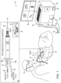
- Fig. 1 is a schematic, pictorial view, along with a side view, of a phacoemulsification system 10 comprising a processor-controlled irrigation pump 24, in accordance with an embodiment of the present invention.
- phacoemulsification probe 12 (e.g., a handpiece 12) comprises a needle 16 surrounded by an irrigation sleeve 56. Needle 16 is hollow and its lumen is used as an aspiration channel.
- Needle 16 is configured for insertion into a lens capsule 18 of an eye 20 of a patient 19 by a physician 15 to remove a cataract.
- the needle (and irrigation sleeve 56) are shown in inset 25 as a straight object.
- any suitable needle may be used with phacoemulsification probe 12, for example, a curved or bent tip needle commercially available from Johnson & Johnson Surgical Vision, Santa Ana, CA, USA.
- probe 12 includes a sensor 23 coupled with irrigation channel 43a, and a sensor 27 coupled with aspiration channel 46a.
- Channels 43a and 46a are coupled respectively to irrigation line 43 and aspiration line 46.
- Sensors 23 and 27 may be any sensor known in the art, including, but not limited to a vacuum sensor or flow sensor.
- the sensor measurements e.g. pressure, vacuum, and/or flow
- the sensor measurements are taken close to the proximal end of the handpiece where the irrigation outlet and the aspiration inlet are located, so as to provide processor 38 an accurate indication of the actual measurements occurring within an eye and provide a short response time to a control loop comprised in processor 38.
- a vacuum sensor as discussed herein includes types of pressure sensors that are configured to provide sufficiently accurate measurements of low sub-atmospheric pressures within a typical sub-pressures range at which aspiration is applied (e.g., between 1 mmHg and 650 mmHg).
- a typical sub-pressures range at which aspiration is applied e.g., between 1 mmHg and 650 mmHg.
- the same pressure sensor model is used to measure irrigation pressure and aspiration sub-pressure, using different sensor settings/calibrations.
- processor-controlled pump 24 comprised in a console 28 pumps irrigation fluid from an irrigation reservoir or tank (shown in Fig. 2 ) via irrigation sleeve 56, to irrigate the eye.
- the fluid is pumped via irrigation tubing line 43 running from console 28 to probe 12.
- Irrigation pump 24 may be any pump known in the art, for example, a peristaltic pump, and using sensors (e.g. as indicated by sensors 23 and/or 27), processor 38 controls a pump rate of irrigation pump 24 to maintain intraocular pressure within prespecified limits.
- Eye fluid and waste matter are aspirated via hollow needle 16 to a collection receptacle (not shown) by a processor-controlled aspiration pump 26 also comprised in console 28 and using aspiration tubing line 46 running from probe 12 to console 28.
- processor 38 controls an aspiration rate of aspiration pump 26 to maintain intraocular pressure (in case of sub-pressure indicated, for example, by sensor 27) within prespecified limits.
- phacoemulsification probe 12 includes a piezoelectric crystal 55, coupled to a horn (not shown), that drives needle 16 to vibrate in a resonant vibration mode that is used to break a cataract into small pieces during a phacoemulsification procedure.
- Console 28 comprises a piezoelectric drive module 30, coupled with the piezoelectric crystal, using electrical wiring running in cable 33.
- Drive module 30 is controlled by a processor 38 that uses the drive signal or a small-amplitude monitoring signal (e.g.
- Processor 38 further conveys processor-controlled driving signals via cable 33 to, for example, maintain needle 16 at maximal vibration amplitude.
- the drive module may be realized in hardware or software, for example, in a proportional-integral-derivative (PID) control architecture.
- PID proportional-integral-derivative
- Processor 38 may receive user-based commands via a user interface 40, which may include setting a vibration mode and/or frequency of the piezoelectric crystal, and setting or adjusting an irrigation and/or aspiration rate of the irrigation pump 24 and aspiration pump 26.
- Processor 38 may receive user-based commands via a user interface 40, which may include needle 16 stroke amplitude settings and turning on irrigation and/or aspiration.
- the physician uses a foot pedal (not shown) as a means of control. For example, pedal position one activates only irrigation, pedal position two activates both irrigation and aspiration, and pedal position three adds needle 16 vibration.
- processor 38 may receive the user-based commands from controls located in a handle 21 of probe 12.
- user interface 40 and display 36 may be integrated into a touch screen graphical user interface.
- processor 38 may be combined in a single physical component or, alternatively, implemented using multiple physical components. These physical components may comprise hard-wired or programmable devices, or a combination of the two. In some embodiments, at least some of the functions of processor 38 may be carried out by suitable software stored in a memory 35 (as shown in Fig. 1 ). This software may be downloaded to a device in electronic form, over a network, for example. Alternatively, or additionally, the software may be stored in tangible, non-transitory computer-readable storage media, such as optical, magnetic, or electronic memory.
- Fig. 1 may include further elements, which are omitted for clarity of presentation.
- physician 15 typically performs the procedure using a stereo microscope or magnifying glasses, neither of which are shown.
- Physician 15 may use other surgical tools in addition to probe 12, which are also not shown in order to maintain clarity and simplicity of presentation.
- Fig. 2 is a block diagram schematically describing processor-controlled irrigation and aspiration sub-systems of phacoemulsification system 10 of Fig. 1 , in accordance with an embodiment of the present invention.
- processor 38 controls (240) irrigation pump 24 to pump balanced salt solution from an irrigation tank 48 to sleeve 56 (shown in Fig. 1 ), via irrigation line 43.
- processor 38 controls (260) aspiration pump 26 to aspirate eye fluid into a collection bag 62, via aspiration line 46.
- Pumps 24 and 26 may include means to indicate actual pump performance (e.g., speed) to processor 38, for use by a feedback loop.
- sensor 23 and sensor 27 of probe 12 provide readings 230 (e.g. pressure, vacuum, or flow) of irrigation channel 43a, and readings 270 (e.g. pressure, vacuum, or flow) of aspiration channel 46a, respectively, to processor 38.
- the readings (230, 270) are provided in real time at a sufficiently high rate (e.g., 1 kHz) to allow a fast system response time (e.g., within several milliseconds).
- sensors 23 and 27 are seen as located in the back of handpiece 12.
- the sensors can be located in a case or module coupled with the handpiece (e.g., by including the sensors in a disposable case coupled to the aspiration and irrigation lines just proximally of the handle itself).
- processor 38 In response to readings (230, 270), adjusts a rate of pumping of irrigation pump 24 and/or aspiration pump 26, to maintain readings (230, 270) within prespecified limits.
- a typical system may include, for example, a complex aspiration apparatus, which may include two or more pumps, including a venturi pump.
- a phacoemulsification system such as shown in of Fig. 1 , additionally includes bypass protection, and may further include valves in irrigation/or aspiration lines.
- irrigation pump 24 represents an irrigation sub-system and aspiration pump 26 represents an aspiration sub-system, with their disclosed functionality described in essence above.
- sensors 23 and 27 comprise the same pressure sensor model, with different settings/calibrations to measure either irrigation pressure or aspiration sub-pressure.
- a sensor may be the aforementioned pressure sensor, or a fluid flow rate meter.
- Fig. 3 is a flow chart schematically illustrating a method for adaptively operating irrigation pump (24) and aspiration (26) pump of the irrigation and aspiration subsystems of Fig. 2 .
- the algorithm carries out a process that begins with needle insertion step 102, during which physician 15 inserts phacoemulsification needle 16 of probe 12 into a lens capsule 18 of an eye 20.
- physician 15 vibrates needle 16 to break up a cataract and, at the same time, processor 38 activates the aforementioned irrigation pump 24 and aspiration pump 26.
- processor 38 receives readings (230, 270) from irrigation and aspiration channels 43 and 46, acquired by sensors 23 and 27, respectively, which early-indicate (e.g., within several mSec) a change in IOP outside a prespecified limit, at a drop in IOP indication receiving step 106.
- processor 38 uses the early indication (e.g., at least one of readings (230, 270))
- processor 38 calculates required changes in rates of pumps 24 and 26, and using the feedback loop that receives the early indication (e.g., feedback signals), processor 38 commands pumps 24 and 26 to adjust pump rates such that readings (230 and 270), indicative of the IOP, are maintained within prespecified limits, at pumps control step 108.
- Fig. 3 The example flow chart shown in Fig. 3 is chosen purely for the sake of conceptual clarity. For example, additional steps, such as controlling pumping systems 24 and 26, are omitted for simplicity and clarity of presentation. Furthermore, various irrigation/aspiration termination criteria, such as, for example, if a predefined number of control cycles fails to bring pressures to within limits, or if the failure is due to other problems, are omitted for simplicity of presentation.
- processor 38 checks if readings (230, 270) are within prespecified limits or ranges, e.g. above or below a threshold or between two set points. If they do, processor 38 continues applying the same irrigation and aspiration rates and the process returns to reading step 106. If they do not, processor 38 checks if the reading is outside the limits or range, e.g. is too high (indicating a risk of vacuum surge has been detected). If the reading is too high, processor 38 increases irrigation rate and/or lowers aspiration rate. The entire cycle described above (as well as the cycles described below), where readings are checked and corrective actions applied, typically requires no more than few milliseconds, thereby protecting the eye from any damage caused by irrigation and/or aspiration problems.
- processor 38 may command pump 24 to lower irrigation flow. In yet another case, if reading 230 is too low (e.g., irrigation flow is insufficient), processor 38 may command pump 24 to increase irrigation flow.
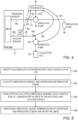
- Fig. 4 is a block diagram schematically describing processor-controlled irrigation and aspiration sub-systems of phacoemulsification system 10 of Fig. 1 , in accordance with another embodiment of the present invention.
- processor 38 controls (403) irrigation pump 24 to pump balance salt solution from an irrigation tank 48 to sleeve 56, via irrigation line 43.
- processor 38 controls (404) aspiration pump 26 to aspirate eye fluid into a collection bag 62, via aspiration line 46.
- Pumps 24 and 26 may include means to indicate actual pump performance (e.g., speed) to processor 38, for use by the feedback loop.
- electrical impedance of crystal 55 is sensed with readings (402), to detect occlusion and perform preemptive steps, such as adjusting irrigation rate and/or adjusting aspiration rate to prevent subsequent vacuum surge.
- Readings (402) are provided in real time at a sufficiently high rate (e.g., 1 kHz) to allow a fast system response time (e.g., within several milliseconds).
- a sufficiently high rate e.g. 1 kHz
- a fast system response time e.g., within several milliseconds.
- processor 38 In response to readings (402), adjusts a rate of pumping of irrigation pump 24 and/or aspiration pump 26, until readings (402) return to prespecified limits or ranges, e.g. above or below a threshold or between two set points.
- the flow of fluids and materials through the system can be regulated by controlling valves, such as controlling (453) valve 443 on the irrigation line and/or controlling (456) valve 446 on the aspiration line.
- the processor is configured to control an operation of irrigation pump 24 and/or aspiration pump 26 by opening and closing valves 443 and/or 446.
- the processor controls an amount of partial opening of valves 443 and/or 446.
- valves can be located inside handpiece 12, be coupled to irrigation and aspiration channels 43a and 46a, just proximally to handpiece 12, or be located elsewhere in the system, such as inside console 28.
- Fig. 5 is a flow chart schematically illustrating a method for adaptively operating irrigation pump (24) and aspiration (26) pump of the irrigation and aspiration subsystems of Fig. 4 .
- the algorithm carries out a process that begins with needle insertion step 502, during which physician 15 inserts phacoemulsification needle 16 of probe 12 into a lens capsule 18 of an eye 20.
- physician 15 vibrates needle 16 to break up a cataract and, at the same time, processor 38 activates the aforementioned irrigation pump 24 and aspiration pump 26.
- processor 38 receives pressure crystal's 55 electrical impedance readings (402) from crystal 55, which early-indicate (e.g., within several mSec) a risk of a change (e.g. drop) in IOP that is above or below a prespecified limit or outside a prespecified range, at a risk of IOP change indication receiving step 506.
- the IOP change may be a drop in IOP below a prespecified limit indicating a possible post occlusion surge risk.
- processor 38 calculates required changes in rates of pumps 24 and 26, and, using the feedback loop that receives the early indication (e.g., feedback signals), processor 38 commands pumps 24 and 26 to adjust pump rates until that readings (402), return to prespecified limits, at pumps control step 508.
- the early indication e.g., feedback signals
Landscapes
- Health & Medical Sciences (AREA)
- Ophthalmology & Optometry (AREA)
- Heart & Thoracic Surgery (AREA)
- Veterinary Medicine (AREA)
- Vascular Medicine (AREA)
- Engineering & Computer Science (AREA)
- Biomedical Technology (AREA)
- Life Sciences & Earth Sciences (AREA)
- Animal Behavior & Ethology (AREA)
- General Health & Medical Sciences (AREA)
- Public Health (AREA)
- Nuclear Medicine, Radiotherapy & Molecular Imaging (AREA)
- Surgery (AREA)
- Hematology (AREA)
- Anesthesiology (AREA)
- External Artificial Organs (AREA)
Claims (4)
- Phakoemulsifikationssystem (10), umfassend:
eine Phakoemulsifikationssonde (12), umfassend:einen piezoelektrischen Kristall (55), der konfiguriert ist, um bei einer mechanischen Resonanzfrequenz des Kristalls zu vibrieren;eine Nadel (16), die konfiguriert ist, um in eine Linsenkapsel (18) eines Auges (20) eingeführt zu werden und durch den piezoelektrischen Kristall in Vibration versetzt zu werden, um eine Linse des Auges zu emulgieren;einen Spülkanal (43a) zum Aufnehmen von Spülfluid aus einer Spülleitung (43) und zum Einströmen des Spülfluids in die Linsenkapsel; undeinen Aspirationskanal (46a) zum Entfernen von Material aus der Linsenkapsel und zum Ableiten des entfernten Materials zu einer Aspirationsleitung (46);eine Spülpumpe (24), die mit der Spülleitung gekoppelt ist;eine Aspirationspumpe (26), die mit der Aspirationsleitung gekoppelt ist;Schaltlogik (30, 33), die konfiguriert ist, um die elektrische Impedanz des piezoelektrischen Kristalls zu messen; undeinen Prozessor (38), der konfiguriert ist, um die gemessene elektrische Impedanz zu empfangen und einen Betrieb der Spülpumpe und der Aspirationspumpe gemäß der gemessenen elektrischen Impedanz zu steuern. - Phakoemulsifikationssystem nach Anspruch 1, wobei der Prozessor konfiguriert ist, um den Betrieb durch gleichzeitiges Betreiben der Spülpumpe und der Aspirationspumpe zu steuern.
- Phakoemulsifikationssystem nach Anspruch 1, wobei der Prozessor konfiguriert ist, um den Betrieb durch Betätigen eines Ventils (443, 446) an mindestens einer der Spülleitung und der Aspirationsleitung zu steuern.
- Phakoemulsifikationssystem nach Anspruch 1,
wobei der Prozessor konfiguriert ist, um den Betrieb durch Betätigen eines Ventils (443, 446) an mindestens einem des Spülkanals und des Aspirationskanals zu steuern.
Applications Claiming Priority (2)
| Application Number | Priority Date | Filing Date | Title |
|---|---|---|---|
| US17/130,846 US20220192878A1 (en) | 2020-12-22 | 2020-12-22 | Processor-controlled pump in irrigation line of phacoemulsification probe |
| PCT/IB2021/061633 WO2022137006A1 (en) | 2020-12-22 | 2021-12-13 | Processor-controlled pump in irrigation line of phacoemulsification probe |
Publications (2)
| Publication Number | Publication Date |
|---|---|
| EP4267058A1 EP4267058A1 (de) | 2023-11-01 |
| EP4267058B1 true EP4267058B1 (de) | 2025-01-01 |
Family
ID=78957709
Family Applications (1)
| Application Number | Title | Priority Date | Filing Date |
|---|---|---|---|
| EP21827670.7A Active EP4267058B1 (de) | 2020-12-22 | 2021-12-13 | Prozessorgesteuerte pumpe in einer spülleitung einer phakoemulsifikationssonde |
Country Status (3)
| Country | Link |
|---|---|
| US (1) | US20220192878A1 (de) |
| EP (1) | EP4267058B1 (de) |
| WO (1) | WO2022137006A1 (de) |
Families Citing this family (14)
| Publication number | Priority date | Publication date | Assignee | Title |
|---|---|---|---|---|
| US12472094B2 (en) | 2020-05-21 | 2025-11-18 | Johnson & Johnson Surgical Vision, Inc. | Phacoemulsification probe comprising magnetic sensors and/or multiple independent piezoelectric vibrators |
| US12178750B2 (en) | 2020-11-23 | 2024-12-31 | Johnson & Johnson Surgical Vision, Inc. | Removal of cataract debris |
| US12324770B2 (en) | 2021-04-15 | 2025-06-10 | Johnson & Johnson Surgical Vision, Inc. | Compensating for imperfect behavior of multi-piezoelectric crystal |
| US12150894B2 (en) * | 2021-04-21 | 2024-11-26 | Johnson & Johnson Surgical Vision, Inc. | Evaluation of phacoemulsification devices |
| US20230039808A1 (en) | 2021-08-07 | 2023-02-09 | Johnson & Johnson Surgical Vision, Inc. | Electronically detecting phacoemulsification tip engagement with a lens |
| US20240197524A1 (en) * | 2022-12-20 | 2024-06-20 | Johnson & Johnson Surgical Vision, Inc. | User selected confidence level for identification of an imminent vacuum surge during phacoemulsification |
| US20240207501A1 (en) * | 2022-12-27 | 2024-06-27 | Johnson & Johnson Surgical Vision, Inc. | Stabilizing intra-ocular pressure at onset of aspiration |
| US20240342003A1 (en) * | 2023-04-17 | 2024-10-17 | Johnson & Johnson Surgical Vision, Inc. | Intraocular pressure fluctuation cancellation |
| US20240350310A1 (en) | 2023-04-19 | 2024-10-24 | Johnson & Johnson Surgical Vision, Inc. | Control of irrigation in a phacoemulsification system |
| US20240350311A1 (en) | 2023-04-19 | 2024-10-24 | Johnson & Johnson Surgical Vision, Inc. | Control of Irrigation in a Phacoemulsification System |
| US20240374808A1 (en) * | 2023-05-08 | 2024-11-14 | Johnson & Johnson Surgical Vision, Inc. | Pressure regulator for ocular surgery |
| US20240398618A1 (en) * | 2023-05-31 | 2024-12-05 | Johnson & Johnson Surgical Vision, Inc. | Phacoemulsification system |
| US20250009556A1 (en) * | 2023-07-07 | 2025-01-09 | Johnson & Johnson Surgical Vision, Inc. | Method and system for cataract tissue sensing |
| CN120907614B (zh) * | 2025-10-10 | 2026-03-20 | 北京速迈医疗科技股份有限公司 | 一种堵塞检测方法、装置、设备、存储介质及程序产品 |
Family Cites Families (12)
| Publication number | Priority date | Publication date | Assignee | Title |
|---|---|---|---|---|
| US5160317A (en) * | 1991-01-03 | 1992-11-03 | Costin John A | Computer controlled smart phacoemulsification method and apparatus |
| US7169123B2 (en) * | 1997-01-22 | 2007-01-30 | Advanced Medical Optics, Inc. | Control of pulse duty cycle based upon footswitch displacement |
| EP2604235A1 (de) * | 2003-03-12 | 2013-06-19 | Abbott Medical Optics Inc. | System und Verfahren zur Bereitstellung gepulster Ultraschallenergie durch Anwendung von Kavitationseffekten |
| US10596033B2 (en) * | 2012-03-26 | 2020-03-24 | Alex Urich | Phacoemulsification ultrasonic device switching between different operational modes |
| US10052227B2 (en) | 2012-09-18 | 2018-08-21 | Liviu B. Saimovici | Cataract removal device and integrated tip |
| US20180318131A1 (en) * | 2012-10-22 | 2018-11-08 | Alcon Research, Ltd. | Pressure control in phacoemulsification system |
| CN104640523B (zh) * | 2012-12-11 | 2017-07-04 | 爱尔康研究有限公司 | 具有集成的抽吸和冲洗泵的白内障超声乳化手柄 |
| US9549850B2 (en) * | 2013-04-26 | 2017-01-24 | Novartis Ag | Partial venting system for occlusion surge mitigation |
| US11185623B2 (en) * | 2017-01-24 | 2021-11-30 | Alcon Inc. | On-demand fluidics system control based on frequency-domain processing |
| US11160602B2 (en) * | 2017-08-29 | 2021-11-02 | Cilag Gmbh International | Control of surgical field irrigation |
| US20190099547A1 (en) | 2017-10-04 | 2019-04-04 | Abbott Medical Optics Inc. | System, Apparatus and Method for Maintaining Anterior Chamber Intraoperative Intraocular Pressure |
| US10940039B2 (en) | 2017-10-31 | 2021-03-09 | Surgical Design Corporation | Automatic ultrasonic phacoemulsification control |
-
2020
- 2020-12-22 US US17/130,846 patent/US20220192878A1/en active Pending
-
2021
- 2021-12-13 EP EP21827670.7A patent/EP4267058B1/de active Active
- 2021-12-13 WO PCT/IB2021/061633 patent/WO2022137006A1/en not_active Ceased
Also Published As
| Publication number | Publication date |
|---|---|
| US20220192878A1 (en) | 2022-06-23 |
| EP4267058A1 (de) | 2023-11-01 |
| WO2022137006A1 (en) | 2022-06-30 |
Similar Documents
| Publication | Publication Date | Title |
|---|---|---|
| EP4267058B1 (de) | Prozessorgesteuerte pumpe in einer spülleitung einer phakoemulsifikationssonde | |
| EP4178508B1 (de) | Aspirationsbypasssteuerung in einer phakoemulsifikationssonde | |
| CA2696344C (en) | Systems and methods for phacoemulsification with vacuum based pumps | |
| AU2013360295A1 (en) | Phacoemulsification hand piece with integrated aspiration and irrigation pump | |
| WO2023170486A1 (en) | Automatic real-time control of activation of phacoemulsification | |
| US20230255824A1 (en) | Tip unclogging using controlled aspiration reflux | |
| WO2023126715A1 (en) | Pulse width modulation (pwm) operated vacuum relief valve in conjunction with an anti-vacuum surge (avs) module | |
| US20240350310A1 (en) | Control of irrigation in a phacoemulsification system | |
| US20240197524A1 (en) | User selected confidence level for identification of an imminent vacuum surge during phacoemulsification | |
| US20240115421A1 (en) | Reducing intraocular pressure (iop) fluctuations during phacoemulsification | |
| US20240358908A1 (en) | Anti-vacuum surge (avs) with improved followability | |
| US20250205082A1 (en) | Control of Irrigation in a Phacoemulsification System | |
| US12042429B2 (en) | Systems and methods for mass air flow control in vacuum based aspiration in surgical system | |
| US20240350311A1 (en) | Control of Irrigation in a Phacoemulsification System | |
| US20240382664A1 (en) | Phacoemulsification vacuum surge detection with correlated vacuum and pressure readings |
Legal Events
| Date | Code | Title | Description |
|---|---|---|---|
| STAA | Information on the status of an ep patent application or granted ep patent |
Free format text: STATUS: UNKNOWN |
|
| STAA | Information on the status of an ep patent application or granted ep patent |
Free format text: STATUS: THE INTERNATIONAL PUBLICATION HAS BEEN MADE |
|
| PUAI | Public reference made under article 153(3) epc to a published international application that has entered the european phase |
Free format text: ORIGINAL CODE: 0009012 |
|
| STAA | Information on the status of an ep patent application or granted ep patent |
Free format text: STATUS: REQUEST FOR EXAMINATION WAS MADE |
|
| 17P | Request for examination filed |
Effective date: 20230721 |
|
| AK | Designated contracting states |
Kind code of ref document: A1 Designated state(s): AL AT BE BG CH CY CZ DE DK EE ES FI FR GB GR HR HU IE IS IT LI LT LU LV MC MK MT NL NO PL PT RO RS SE SI SK SM TR |
|
| DAV | Request for validation of the european patent (deleted) | ||
| DAX | Request for extension of the european patent (deleted) | ||
| GRAP | Despatch of communication of intention to grant a patent |
Free format text: ORIGINAL CODE: EPIDOSNIGR1 |
|
| STAA | Information on the status of an ep patent application or granted ep patent |
Free format text: STATUS: GRANT OF PATENT IS INTENDED |
|
| INTG | Intention to grant announced |
Effective date: 20240726 |
|
| GRAS | Grant fee paid |
Free format text: ORIGINAL CODE: EPIDOSNIGR3 |
|
| GRAA | (expected) grant |
Free format text: ORIGINAL CODE: 0009210 |
|
| STAA | Information on the status of an ep patent application or granted ep patent |
Free format text: STATUS: THE PATENT HAS BEEN GRANTED |
|
| AK | Designated contracting states |
Kind code of ref document: B1 Designated state(s): AL AT BE BG CH CY CZ DE DK EE ES FI FR GB GR HR HU IE IS IT LI LT LU LV MC MK MT NL NO PL PT RO RS SE SI SK SM TR |
|
| REG | Reference to a national code |
Ref country code: GB Ref legal event code: FG4D |
|
| REG | Reference to a national code |
Ref country code: CH Ref legal event code: EP |
|
| REG | Reference to a national code |
Ref country code: DE Ref legal event code: R096 Ref document number: 602021024440 Country of ref document: DE |
|
| REG | Reference to a national code |
Ref country code: IE Ref legal event code: FG4D |
|
| REG | Reference to a national code |
Ref country code: LT Ref legal event code: MG9D |
|
| REG | Reference to a national code |
Ref country code: NL Ref legal event code: MP Effective date: 20250101 |
|
| REG | Reference to a national code |
Ref country code: AT Ref legal event code: MK05 Ref document number: 1755512 Country of ref document: AT Kind code of ref document: T Effective date: 20250101 |
|
| PG25 | Lapsed in a contracting state [announced via postgrant information from national office to epo] |
Ref country code: NL Free format text: LAPSE BECAUSE OF FAILURE TO SUBMIT A TRANSLATION OF THE DESCRIPTION OR TO PAY THE FEE WITHIN THE PRESCRIBED TIME-LIMIT Effective date: 20250101 |
|
| PG25 | Lapsed in a contracting state [announced via postgrant information from national office to epo] |
Ref country code: FI Free format text: LAPSE BECAUSE OF FAILURE TO SUBMIT A TRANSLATION OF THE DESCRIPTION OR TO PAY THE FEE WITHIN THE PRESCRIBED TIME-LIMIT Effective date: 20250101 |
|
| PG25 | Lapsed in a contracting state [announced via postgrant information from national office to epo] |
Ref country code: PL Free format text: LAPSE BECAUSE OF FAILURE TO SUBMIT A TRANSLATION OF THE DESCRIPTION OR TO PAY THE FEE WITHIN THE PRESCRIBED TIME-LIMIT Effective date: 20250101 |
|
| PG25 | Lapsed in a contracting state [announced via postgrant information from national office to epo] |
Ref country code: ES Free format text: LAPSE BECAUSE OF FAILURE TO SUBMIT A TRANSLATION OF THE DESCRIPTION OR TO PAY THE FEE WITHIN THE PRESCRIBED TIME-LIMIT Effective date: 20250101 |
|
| PG25 | Lapsed in a contracting state [announced via postgrant information from national office to epo] |
Ref country code: NO Free format text: LAPSE BECAUSE OF FAILURE TO SUBMIT A TRANSLATION OF THE DESCRIPTION OR TO PAY THE FEE WITHIN THE PRESCRIBED TIME-LIMIT Effective date: 20250401 Ref country code: IS Free format text: LAPSE BECAUSE OF FAILURE TO SUBMIT A TRANSLATION OF THE DESCRIPTION OR TO PAY THE FEE WITHIN THE PRESCRIBED TIME-LIMIT Effective date: 20250501 |
|
| PG25 | Lapsed in a contracting state [announced via postgrant information from national office to epo] |
Ref country code: HR Free format text: LAPSE BECAUSE OF FAILURE TO SUBMIT A TRANSLATION OF THE DESCRIPTION OR TO PAY THE FEE WITHIN THE PRESCRIBED TIME-LIMIT Effective date: 20250101 |
|
| PG25 | Lapsed in a contracting state [announced via postgrant information from national office to epo] |
Ref country code: LV Free format text: LAPSE BECAUSE OF FAILURE TO SUBMIT A TRANSLATION OF THE DESCRIPTION OR TO PAY THE FEE WITHIN THE PRESCRIBED TIME-LIMIT Effective date: 20250101 Ref country code: PT Free format text: LAPSE BECAUSE OF FAILURE TO SUBMIT A TRANSLATION OF THE DESCRIPTION OR TO PAY THE FEE WITHIN THE PRESCRIBED TIME-LIMIT Effective date: 20250502 |
|
| PG25 | Lapsed in a contracting state [announced via postgrant information from national office to epo] |
Ref country code: GR Free format text: LAPSE BECAUSE OF FAILURE TO SUBMIT A TRANSLATION OF THE DESCRIPTION OR TO PAY THE FEE WITHIN THE PRESCRIBED TIME-LIMIT Effective date: 20250402 Ref country code: BG Free format text: LAPSE BECAUSE OF FAILURE TO SUBMIT A TRANSLATION OF THE DESCRIPTION OR TO PAY THE FEE WITHIN THE PRESCRIBED TIME-LIMIT Effective date: 20250101 |
|
| PG25 | Lapsed in a contracting state [announced via postgrant information from national office to epo] |
Ref country code: AT Free format text: LAPSE BECAUSE OF FAILURE TO SUBMIT A TRANSLATION OF THE DESCRIPTION OR TO PAY THE FEE WITHIN THE PRESCRIBED TIME-LIMIT Effective date: 20250101 |
|
| PG25 | Lapsed in a contracting state [announced via postgrant information from national office to epo] |
Ref country code: CZ Free format text: LAPSE BECAUSE OF FAILURE TO SUBMIT A TRANSLATION OF THE DESCRIPTION OR TO PAY THE FEE WITHIN THE PRESCRIBED TIME-LIMIT Effective date: 20250101 |
|
| PG25 | Lapsed in a contracting state [announced via postgrant information from national office to epo] |
Ref country code: SE Free format text: LAPSE BECAUSE OF FAILURE TO SUBMIT A TRANSLATION OF THE DESCRIPTION OR TO PAY THE FEE WITHIN THE PRESCRIBED TIME-LIMIT Effective date: 20250101 |
|
| REG | Reference to a national code |
Ref country code: DE Ref legal event code: R097 Ref document number: 602021024440 Country of ref document: DE |
|
| PG25 | Lapsed in a contracting state [announced via postgrant information from national office to epo] |
Ref country code: SM Free format text: LAPSE BECAUSE OF FAILURE TO SUBMIT A TRANSLATION OF THE DESCRIPTION OR TO PAY THE FEE WITHIN THE PRESCRIBED TIME-LIMIT Effective date: 20250101 |
|
| PG25 | Lapsed in a contracting state [announced via postgrant information from national office to epo] |
Ref country code: DK Free format text: LAPSE BECAUSE OF FAILURE TO SUBMIT A TRANSLATION OF THE DESCRIPTION OR TO PAY THE FEE WITHIN THE PRESCRIBED TIME-LIMIT Effective date: 20250101 |
|
| PG25 | Lapsed in a contracting state [announced via postgrant information from national office to epo] |
Ref country code: IT Free format text: LAPSE BECAUSE OF FAILURE TO SUBMIT A TRANSLATION OF THE DESCRIPTION OR TO PAY THE FEE WITHIN THE PRESCRIBED TIME-LIMIT Effective date: 20250101 |
|
| PG25 | Lapsed in a contracting state [announced via postgrant information from national office to epo] |
Ref country code: EE Free format text: LAPSE BECAUSE OF FAILURE TO SUBMIT A TRANSLATION OF THE DESCRIPTION OR TO PAY THE FEE WITHIN THE PRESCRIBED TIME-LIMIT Effective date: 20250101 |
|
| PG25 | Lapsed in a contracting state [announced via postgrant information from national office to epo] |
Ref country code: RO Free format text: LAPSE BECAUSE OF FAILURE TO SUBMIT A TRANSLATION OF THE DESCRIPTION OR TO PAY THE FEE WITHIN THE PRESCRIBED TIME-LIMIT Effective date: 20250101 |
|
| PG25 | Lapsed in a contracting state [announced via postgrant information from national office to epo] |
Ref country code: SK Free format text: LAPSE BECAUSE OF FAILURE TO SUBMIT A TRANSLATION OF THE DESCRIPTION OR TO PAY THE FEE WITHIN THE PRESCRIBED TIME-LIMIT Effective date: 20250101 |
|
| PLBE | No opposition filed within time limit |
Free format text: ORIGINAL CODE: 0009261 |
|
| STAA | Information on the status of an ep patent application or granted ep patent |
Free format text: STATUS: NO OPPOSITION FILED WITHIN TIME LIMIT |
|
| 26N | No opposition filed |
Effective date: 20251002 |
|
| PGFP | Annual fee paid to national office [announced via postgrant information from national office to epo] |
Ref country code: DE Payment date: 20251028 Year of fee payment: 5 |