EP4266832A1 - Infrastructure monitoring by led driver - Google Patents
Infrastructure monitoring by led driver Download PDFInfo
- Publication number
- EP4266832A1 EP4266832A1 EP22169373.2A EP22169373A EP4266832A1 EP 4266832 A1 EP4266832 A1 EP 4266832A1 EP 22169373 A EP22169373 A EP 22169373A EP 4266832 A1 EP4266832 A1 EP 4266832A1
- Authority
- EP
- European Patent Office
- Prior art keywords
- building infrastructure
- parameter
- circuit
- mains supply
- infrastructure system
- Prior art date
- Legal status (The legal status is an assumption and is not a legal conclusion. Google has not performed a legal analysis and makes no representation as to the accuracy of the status listed.)
- Pending
Links
Images

Classifications
-
- H—ELECTRICITY
- H05—ELECTRIC TECHNIQUES NOT OTHERWISE PROVIDED FOR
- H05B—ELECTRIC HEATING; ELECTRIC LIGHT SOURCES NOT OTHERWISE PROVIDED FOR; CIRCUIT ARRANGEMENTS FOR ELECTRIC LIGHT SOURCES, IN GENERAL
- H05B47/00—Circuit arrangements for operating light sources in general, i.e. where the type of light source is not relevant
- H05B47/10—Controlling the light source
- H05B47/105—Controlling the light source in response to determined parameters
-
- H—ELECTRICITY
- H05—ELECTRIC TECHNIQUES NOT OTHERWISE PROVIDED FOR
- H05B—ELECTRIC HEATING; ELECTRIC LIGHT SOURCES NOT OTHERWISE PROVIDED FOR; CIRCUIT ARRANGEMENTS FOR ELECTRIC LIGHT SOURCES, IN GENERAL
- H05B47/00—Circuit arrangements for operating light sources in general, i.e. where the type of light source is not relevant
- H05B47/10—Controlling the light source
- H05B47/175—Controlling the light source by remote control
- H05B47/196—Controlling the light source by remote control characterised by user interface arrangements
-
- H—ELECTRICITY
- H05—ELECTRIC TECHNIQUES NOT OTHERWISE PROVIDED FOR
- H05B—ELECTRIC HEATING; ELECTRIC LIGHT SOURCES NOT OTHERWISE PROVIDED FOR; CIRCUIT ARRANGEMENTS FOR ELECTRIC LIGHT SOURCES, IN GENERAL
- H05B45/00—Circuit arrangements for operating light-emitting diodes [LED]
- H05B45/10—Controlling the intensity of the light
- H05B45/18—Controlling the intensity of the light using temperature feedback
Definitions
- the invention relates to the field of technical building infrastructure and, in particular, concerns a monitoring system for using light driver devices for obtaining and evaluating external parameters commonly acting on a plurality of devices, and a corresponding monitoring method.
- the technical building infrastructure includes infrastructure systems that typically arrange a large number of devices over the extensive area of a building.
- the devices may include luminaires, lighting modules for emitting light, driver devices for driving the lighting modules, presence detectors, switches, dimmers, further control gear, lighting system management servers, dedicated communication equipment for a DALI TM , Bluetooth mesh (Casambi ZigBee TM , etc) or IP based network (matter), and emergency power supply including batteries for storing electric energy.
- a power grid within the building provides electric energy via mains supply to the devices of the lighting system and extends over the entire building.
- the mentioned devices of the lighting system include electrical circuitry consisting of electrical components, whose lifespan may depend on the respective temperature profiles they experience over their service life and on the characteristics of the mains supply over time. For example, frequent occurrences of voltage surges or spikes on the mains supply lines may adversely affect the lifespan of a connected electric circuit, and therefore the respective device.
- the first aspect concerns the monitoring system for monitoring at least one parameter in an environment of a building infrastructure system.
- the building infrastructure system includes the monitoring system, and the monitoring system comprises a sensor circuit for obtaining sensor data on the at least one parameter and providing this data, wherein the sensor circuit is arranged in a building infrastructure device of the building infrastructure system.
- the monitoring system further comprises an evaluator circuit for generating an evaluation signal by evaluating the sensor data provided by the sensor circuit.
- the at least one parameter is an external parameter such as an environmental parameter or a technical parameter, which commonly influences a plurality of devices of the building infrastructure system.
- the monitoring system is configured to provide the evaluation signal to at least one other device.
- the monitoring system increases the functionality of the building infrastructure device beyond its basic function, which comprises, for example, providing light, in order to add the functionality of acting as a diagnostic device for external parameters.
- the building infrastructure system arranges a plurality of infrastructure devices, for example LED drivers, all over the building. All individual infrastructure devices may be connected with mains supply. If then, for example, a surge voltage occurs on the mains supply line, the infrastructure device can detect the mains voltage surge via the sensor circuit.
- the individual luminaires and light driver devices are connected via a communication network, and an intelligent lighting control, based on a DALI, Bluetooth mesh or IP based network for example, becomes increasingly state-of-the-art.
- the following explanations may use DALI as an example. However, the explanations are also valid for the other mentioned network systems.
- the LED driver device connected to the lighting system via the DALI network provides the data generated by the LED driver on the driver device, which are used for additional applications as well, for example, tracking of power consumption, tracking of the LED current, communicating an actual demo letter, indicating current failure modes.
- internal states of the driver devices may be determined and the internal states communicated via DALI 2 interface of the driver device to interfaces of other devices, and in particular to a light management server.
- the invention now uses the building infrastructure device as a diagnostic device for measuring external parameters, which are valid for and make an impact on a plurality of devices.
- the external parameters influence the interface between each device of a plurality of devices and a common environment of the devices.
- the monitoring system monitors parameters characterizing a mains supply, or an ambient temperature, or a humidity level or a dust level of a common environment of the common environment of the building infrastructure devices, and thus over the space covered by the building infrastructure system.
- the monitoring system reports in the evaluation signal detected events based on the monitored parameters to other building infrastructure devices, for example to a system management server, or to other light driver devices.
- the provided sensor data may enable to determine where to arrange new building infrastructure devices within the building by taking humidity and ambient temperature for potential locations into account.
- the building infrastructure device now senses and provides parameter data on its vicinity and the environment surrounding the building infrastructure device, which enables to deduce a current state of other devices located in the same environment, for example, a nearby machine.
- the machine may emit an unusual amount of heat thereby increasing the ambient temperature around the building infrastructure device.
- Communicating the evaluation signal via a communication interface of the building infrastructure device to other building infrastructure devices or a central control server of the building infrastructure system enables to implement additional functions for the building infrastructure system, which extend beyond its intended basic purpose of, for example, providing light to the environment.
- the building infrastructure system is a lighting system
- the building infrastructure device is a light driver device, and in particular an LED driver device.
- the at least one other infrastructure device includes a system management server (12) or a light driver device, in particular an LED driver device.
- Current LED drivers often include a communication interface, e.g. implementing a communication capability based on a light standard such as DALI RTM or DALI 2 RTM standard, which enables to provide at least one of the sensor data including obtained parameter values, and the evaluation signal generated based on the sensor data, to other elements of the lighting system.
- a communication interface e.g. implementing a communication capability based on a light standard such as DALI RTM or DALI 2 RTM standard, which enables to provide at least one of the sensor data including obtained parameter values, and the evaluation signal generated based on the sensor data, to other elements of the lighting system.
- current LED drivers may already include already basic measurement capabilities concerning a mains supply current and the mains supply voltage, for example for estimating a power consumption as an internal parameter of the LED driver.
- the monitoring system extends this determination of internal parameters of the LED driver to determining external parameters, which are relevant to a plurality of devices forming part of the lighting system.
- Providing the evaluation signal to a central system management server enables analysis of the environment covered by the plurality of individual infrastructure devices with respect to the monitored parameter and variations of the monitored parameter over time and with regard to specific events defined based on the monitored parameter.
- Performing predictive maintenance for the infrastructure system becomes possible by a further evaluation of at least one of the sensor data and the evaluation signal.
- Based on gained knowledge on, for example, the ambient temperature over time, or characteristics of the mains supply replacement of faulty equipment with infrastructure devices, which are considered more suited to the particular environment based on historic data on the monitored parameter is now possible.
- neighbouring infrastructure devices may be shut down as a preventive measure, for example, when receiving prediction information from the infrastructure device on this this a potentially harmful event.
- the at least one parameter is an external parameter, which characterizes the environment and/or an interface of a plurality of infrastructure devices including the building infrastructure device and the at least one other infrastructure device.
- the external parameter may include at least one of a characteristic parameter of a mains supply, an ambient temperature, an ambient humidity, and an ambient dust level.
- Mains supply characteristics, temperature ranges or the capability to cope with an environment exhibiting a certain humidity level or level of dust are key requirements for employment of electric devices in the environment of the building infrastructure.
- the monitoring system generates and evaluates sensor data and thereby acquires knowledge on actual parameters values for these key requirements, which supports selecting of suitable device types for a particular infrastructure system, or for suitable replacement devices.
- the characteristic parameter of the mains supply includes at least one of a mains supply voltage, a mains supply input current, a mains supply frequency, a mains supply frequency deviation, a mains supply surge voltage, mains supply under-voltage, mains voltage spikes, mains supply voltage drops at an mains supply interface of the building infrastructure device.
- the ambient temperature may include a global environmental temperature that is independent from an internal temperature (device temperature) of the infrastructure device.
- the evaluator circuit in an embodiment of the monitoring system is configured to detect an event based on the obtained sensor data on the at least one parameter, and to output information on the detected event in the evaluation signal.
- the evaluator circuit maybe configured to detect the event based on the obtained at least one parameter and further based on at least one predefined event pattern for the at least one parameter.
- the evaluator circuit may comprise a memory configured to store a plurality of predefined event patterns for the at least one parameter.
- the monitoring circuit may use learning algorithms for learning specific patterns fur the specific building infrastructure system and its specific environment.
- the evaluator circuit comprises a counter configured to count a number of occurrences of a predefined event detected by the evaluator circuit.
- the event counter enables evaluating those events, which occur with a certain frequency over time.
- the monitoring system comprises an actuator configured to perform an action based on the detected event, wherein the active action comprises outputting a measurement signal to the monitored environment based on the detected event, and measuring a reaction in the monitored environment to the output measurement signal.
- the monitoring system may comprise an actuator configured to perform a passive action based on the detected event, wherein the passive action includes generating an output signal including information on the detected event, and providing the output signal to the at least one other infrastructure device.
- the output signal may indicate the detected event, for example visually on a display to an operator for providing a basis for deciding whether to take a further action based on the detected event.
- the actuator is configured to perform an active action based on the detected event, wherein the active action comprises outputting the measurement signal based on the detected event, and measuring the reaction in the monitored environment in response to the output measurement signal.
- the actuator may include a time domain reflectometer. The time domain reflectometer enables to determine discontinuities on electrical lines, thus on mains supply lines on which, based on the monitored mains supply parameters, an event indicating some sort of failure was detected.
- the monitoring system implements an automated mains supply failure detection, which includes additional information where a failure originating in a faulty mains supply line occurred.
- the information where a failure occurred may include information on which line connected to a mains supply interface of the building infrastructure device, and/or at which distance from the mains supply interface the failure is located.
- the sensor circuit comprises a temperature probe for measuring an ambient temperature in the environment in a vicinity of the building infrastructure device.
- the evaluator circuit is configured to determine and store temperature profiles as temperature patterns, and to determine a state of a machine located in the vicinity based on the measured ambient temperature and the stored determined temperature patterns.
- This embodiment of the monitoring system is advantageous as the building infrastructure system provides the additional functionality of monitoring machines in the environment with only limited additional expense.
- the infrastructure device may comprise a control circuit, in particular a microcontroller or an ASIC configured to perform at least partially functions of the sensor circuit and the evaluator circuit.
- a light driver includes one or plural microcontroller(s), microprocessor(s) or ASICS(s), which provide the capabilities to process signals from sensors and to implement the algorithms for sensor signal evaluation, as well as for generating the evaluation signal and providing the evaluation signal to a communication interface of the lighting device.
- microcontroller(s) microprocessor(s) or ASICS(s)
- ASICS ASICS
- the functionality of the light driver increases without requiring additional hardware, as the control circuit of the light driver provides a hardware basis for the additional functions.
- the monitoring system requires only limited additional space in the building infrastructure device, and may only modestly increase cost of the building infrastructure device.
- the infrastructure device may comprise a voltage divider circuit configured to provide a voltage indicating a mains supply voltage or a mains supply current to an input of the control circuit.
- the voltage divider circuit enables to provide a sensor signal in a suitable voltage range to an A/D-converter input of the control circuit. Thus, only limited additional hardware is necessary for implementing the monitoring system in the building infrastructure device.
- the method for monitoring at least one parameter from an environment of a building infrastructure system solves the aforementioned problem in a third aspect.
- the building infrastructure system includes a monitoring system and the monitoring system comprises a sensor circuit arranged in a building infrastructure device and an evaluator circuit.
- the method comprises a step of obtaining, by the sensor circuit, sensor data on the at least one parameter.
- the method proceeds by generating, by the evaluator circuit, an evaluation signal by evaluating the sensor data obtained by the sensor circuit.
- the at least one parameter is an environmental parameter or a technical parameter, which influences a plurality of devices of the building infrastructure system.
- the method further comprises providing the evaluation signal to at least one other infrastructure device.
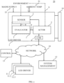
- Figure 1 provides a schematic overview of the structure of a monitoring system for obtaining at least one parameter according to the first embodiment.
- Figure 1 shows the monitoring system of figure 1 as part of a building infrastructure system.
- Figure 1 in particular depicts the building infrastructure system as a lighting system 20.
- the lighting system 20 comprises a plurality of structural components arranged in the environment.
- the environment of the lighting system 20 is the interior of a building.
- the environment of the lighting system 1 may include all spaces, which light emitting elements of the lighting system 1, in particular, all lighting modules 14 illuminate or are capable to illuminate.
- Figure 1 shows an example of the functional blocks of an LED driver 1 in a lighting system 20, which includes the monitoring system according to the first aspect.
- the LED driver 1 has a mains supply interface not explicitly shown, which provides the LED driver 1 with electric energy from the power grid of the building.
- the mains supply is characteristically, but not limited to an AC mains supply.
- the mains driver 1 provides a load current to at least one LED lighting module 14.
- the load current may be a DC current.
- the lighting system 20 comprises in particular a plurality of LED drivers 1, 11.1, 11.2, 11.3.
- the LED driver 1 is shown in more detail than the further LED drivers 11.1, 11.2, 11.3.
- each LED driver 1, 11.1, 11.2, 11.3 will further include elements such as a rectifier circuit, a power factor correction (PFC) circuit, a DC/DC converter circuit, a control circuit, and an LED interface for providing the DC current to the LED lighting module 14.
- PFC power factor correction
- the building has a mains supply grid providing electric energy via a main supply 22 to each of the structural elements of the lighting system 20.
- the environment is further characterized by an ambient temperature 21, which may vary over the entire building and may also vary over time.
- the ambient temperature 21 is a temperature in the vicinity of the LED driver 1, and is different from a device temperature of the LED driver 1, which is a temperature within an enclosure of the LED driver 1.
- the device temperature of the LED driver 1 depends to a large extent or almost entirely on the heat dissipation of the electronic circuitry of the LED driver 1.
- the ambient temperature is a temperature outside the enclosure (housing) of the LED driver 1.
- the ambient temperature is influenced by the device temperature of the LED driver 1, but also reflects an ambient air temperature at the location of the LED driver 1, temperature increasing effects and temperature decreasing effects. Temperature Increasing effects include influence by other heat radiating sources, for example machines arranged near the location of the LED driver 1, and temperature decreasing effects include for example by open windows, working ventilators or HVC equipment near to the LED driver 1.
- the LED driver 1 includes a communication interface 6.
- the communication interface 6 enables the LED driver one to communicate with other elements of the lighting system 20 via a lighting network 10 (network 10).
- the communication interface 6 may be an interface according to the Digital Addressable Lighting Interface DALI RTM) standard, the DALI-2 RTM standard, D4i standard or any other interface standard applied in the field of technical building infrastructure.
- the network 10 may be a wired communication network or, alternatively, a wireless network.
- the network 10 may use both wired and wireless communication.
- the lighting system 20 further includes at least one control module 13.
- the control module 13 may be a light switch, a dimming module, which enables to control light emission of the LED lighting module(s) 14 by controlling the load current output by the respective LED driver 1, 11.1, 11.2, 11.3.
- the control module 13 communicates with the other elements of the lighting system 20 via the network 10.
- the control module 13 may include one or more elements, which are in wired connection with at least one LED driver 1, 11.1, 11.2, 11.3, and/or the system management server 12.
- system management server 12 may be a central server in direct connection via the network 10 with all of the other elements of the lighting system 20. Additionally or alternatively, the system management server 12 may communicate via the network 10 with one or a plurality of edge gateway units on one or more intermediate layers of the lighting system 20.
- the first embodiment of the lighting system 20 includes an LED driver 1, which comprises key elements of the monitoring system according to the first aspect.
- the monitoring system comprises the sensor circuit 2 and the evaluation circuit 3.
- the LED driver 1 comprises the sensor circuit 2, the evaluator circuit 3 and the communication interface 6.
- the sensor circuit 2 is arranged in the LED lighting driver 1.
- the sensor circuit 2 obtains sensor data on the at least one parameter.
- Obtaining sensor data on the at least one parameter may comprises measuring actual values for the at least one parameter.
- Obtaining sensor data on the at least one parameter may comprises determining representative values for the actual values of the at least one parameter.
- the at least one parameter is an environmental parameter or a technical parameter, which influences a plurality of devices of the building infrastructure system 20.
- the at least one parameter is an external parameter, which characterizes the environment and/or an interface of a plurality of infrastructure devices including the LED driver 1 and at least one other device of the other LED driver(s) 11.1, 11.2, 11.3, the control module 13, the system management server 12, or other devices in the environment of the lighting system 1.
- Machines may include office machines, e.g. a computer, a printer, a scanner, work machines in a manufacturing environment, e.g. a milling machine, a lathe (turning machine), or food processing machines in a kitchen environment.
- office machines e.g. a computer, a printer, a scanner, work machines in a manufacturing environment, e.g. a milling machine, a lathe (turning machine), or food processing machines in a kitchen environment.
- the external parameter may include at least one of a characteristic parameter of the mains supply 22.
- the characteristic parameter of the mains supply 22 may include at least one of a mains supply voltage, a mains supply input current, a mains supply frequency, a mains supply frequency deviation, a mains supply surge voltage, a mains supply under-voltage, a mains voltage spikes, a mains supply voltage drops.
- the external parameter may include at least one of an ambient temperature 21, an ambient humidity, and an ambient dust level in the environment of the LED driver 1.
- the ambient temperature 21 may include a global environmental temperature that is independent from an internal temperature of the infrastructure device 1.
- the sensor circuit 2 provides the obtained sensor data 8 to the evaluator circuit 3.
- the LED driver 1 arranges the evaluator circuit 3 in the enclosure of the LED driver 1.
- the LED driver 1 may implement the evaluator circuit 3 and even part of the sensor circuit 2 in a microcontroller of the LED driver 1.
- the microcontroller 7 may be part of a control circuit 7 of the LED driver 1.
- the evaluator circuit 3 generates an evaluation signal 4 by evaluating the sensor data 8 obtained by the sensor circuit 2.
- Evaluating the sensor data 8 may include detecting an event based on the obtained sensor data 8 of the at least one parameter.
- the evaluator circuit 3 may detect the event based on the obtained sensor data 8 and further based on at least one predefined event pattern for the at least one parameter.
- the evaluator circuit 3 may, for example comprise a memory, which stores a plurality of predefined event patterns for the at least one parameter.
- the evaluator circuit 3 compares the obtained sensor data 8 with the stored predefined event patterns, and determine whether one of the stored event patterns has sufficient similarity with the obtained sensor data 8. In case one of the event patterns has sufficient similarity with the obtained sensor data 8, the evaluator circuit 3 determines that a particular event associated with the predefined event pattern with a high similarity with the current sensor data 8 is detected.
- the evaluator circuit 3 may compare the obtained sensor data 4 with a predetermined threshold. In case the obtained sensor data 4 is equal to or exceeds the predetermined threshold, the evaluator circuit 3 determines a particular event associated with the threshold is detected.
- the evaluator circuit 3 may include an event counter for a particular event, which is increased or decreased each time evaluator circuit 3 detects the particular event.
- the evaluation signal 4 may include information on any event, which is detected by the evaluator circuit 3.
- the evaluation signal 4 includes information on a number of detected occurrences for at least one event, based on the obtained sensor data.
- the evaluation signal 4 may be generated and output each time the evaluator circuit 3 detects an event. Alternatively or additionally, the evaluator circuit 3 is adapted to generate the evaluation signal at regular or irregular time intervals.
- generation and output of the evaluation signal 4 may be externally requested.
- an operator may request via a user interface of the system management server 12 data on the at least one parameter.
- the evaluator circuit 3 may in response to the request transmitted via the network 10 to the LED driver 1 obtain sensor data 4 and evaluate the obtained sensor data 4 and generate the evaluation signal 4 based on the obtained sensor data 4.
- the evaluator circuit 3 may in response to the request transmitted via the network 10 to the LED driver 1, evaluate currently obtained sensor data 4 and sensor data obtained in the past and stored in a memory of the evaluator circuit 3. The evaluator circuit 3 may then generate the evaluation signal 4 based on the current sensor data 4 and the past sensor data 4.
- the evaluator circuit 3 outputs the generated information on the detected event in the evaluation signal 4.
- the evaluator circuit 3 outputs the evaluation signal 4 to the communication interface 6.
- the communication interface 6 generates a communication signal including the evaluation signal, or at least the information included in the evaluation signal 6, and outputs the generated communication signal via the network 10 to at least one of the control module 13, the LED drivers 11.1, 11.2, 11.3 and the system management server 12.
- the monitoring system provides the evaluation signal 4 to at least one other infrastructure device 11.1, 11.2, 11.3, 12 of the lighting system 20.
- the monitoring system provides the evaluation signal 4 via the communication interface 6 and the network 10 to at least one of the control module 13, the LED drivers 11.1, 11.2, 11.3, and the system management server 12.
- the LED driver 1 additionally includes an actuator 5.
- the actuator 5 is configured to perform an action based on the detected event.
- the actuator 5 may perform the action based on the evaluator signal received from the evaluator circuit 3.
- the monitoring system may distinguish between active actions and passive actions.
- the active action may comprise generating and outputting a measurement signal 9 to the monitored environment based on the detected event in the evaluation signal 4.
- the actuator 5 proceeds then with determining a reaction in the monitored environment to the output measurement signal 9.
- the actuator comprises a time domain reflectometer, which may be connectable to each of the power supply lines of the mains supply interface of the LED driver 1.
- the measurement signal includes a measurement pulse generated and output by the time domain reflectometer.
- the monitored environment includes the power supply lines of the mains supply of the LED driver 1.
- the reaction of the monitored environment includes in this example a at least partial reflection of the measurement pulse at a discontinuity of a power supply line, which was already indicated by a voltage drop as a detected event in the evaluation signal 4.
- the evaluator circuit 3 is configured to initiate a further measurement as the active action performed by the actuator 5.
- the measured reaction by the actor 5 may then be output to the system management server 12 via the network 10.
- a passive action may include presenting the obtained information on a detected event to an operator via a user interface of the system management server 12.
- the passive action may include storing the evaluation signal or at least the information included in a data storage of the system management server 12 or associated with the system management server 12.
- Figure 2 provides a schematic overview over of a monitoring system for obtaining the at least one parameter according to a second embodiment.
- figure 2 shows an example of the functional blocks of an LED driver 1' in a lighting system 21, which includes the monitoring system according to the first aspect.
- the second embodiment differs from the first embodiment with regard to the arrangement of the evaluation circuit 3' of the LED driver 1'.
- the sensor circuit 2 of the LED driver 1' generates a monitoring signal 8' including the obtained sensor data 4 with current parameter values for the at least one parameter and provides the generated monitoring signal 8' to the communication interface 6.
- the communication interface 6 transmits the monitoring signal 8' via the network 10 to the evaluator circuit 3'.
- the evaluator circuit 3' of the second embodiment may include a communication interface 3.1 for communicating via the network 10. This enables to implement the evaluator circuit 3' independent from the LED driver 1'. The complexity of the LED driver 1' of the second embodiment is therefore smaller compared with the LED driver 1 of the first embodiment.
- the evaluator circuit 3' may evaluate sensor data 4 included in the monitoring signals 4' provided by a plurality of LED drivers 1', 11.1', 11.2', 11.3'.
- the evaluator circuit 3' may be co-located with the system management server 12. In particular, the evaluator circuit 3'may be hosted on a same processing hardware as the system management server 12. The evaluator circuit 3' provides the evaluation signal 4' corresponding to the evaluation signal 4 of the first embodiment directly, in particular without taking a route over the network 10 to the system management server 12.
- the second embodiment may locate the evaluator circuit 3' at an intermediate layer of the lighting system 20', for example at an edge gateway device not depicted in the figures.
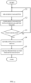
- Fig. 3 is a simplified flowchart of the method for monitoring at least one parameter from an environment using a monitoring system in a building infrastructure system according to an embodiment.
- the method for monitoring at least one parameter from an environment uses a monitoring system in a building infrastructure system 20, 20'.
- the monitoring system comprises the sensor circuit 2 arranged in an infrastructure device 1, 1', and the evaluator circuit 3, 3'.
- the method starts with a step Si of the sensor circuit 1, 1' obtaining the sensor data 4 on the at least one parameter.
- step S2 the evaluator circuit 3, 3' evaluates the obtained sensor data 8 of the at least one parameter, and generates an evaluation signal 4 based on the evaluated at least one parameter.
- the method may compare the obtained sensor data 4 of the at least one parameter, its obtained current parameter value with stored parameter values of the at least one parameter, and determine, whether a predefined event has occurred based on the comparison.
- Detecting an event may include comparing the current parameter value with a predefined threshold.
- Detecting an event may include performing a process of pattern recognition based on a plurality of obtained parameter values and on stored predetermined patterns of parameter values.
- Detecting an event may include performing a process of pattern recognition using an obtained sequence of parameter values and stored patterns representing sequences of parameter values.
- Stored patterns of parameter values may include patterns of parameter values, which were learned by performing a machine learning algorithm on obtained sensor data 4.
- detecting an event may include iteratively detecting the occurrence of an event based on the obtained sensor data 4, and in case the event is detected to have occurred, increasing an event counter by a number of detected events, or by 1.
- a further event may then be defined by comparing the current value of the event counter with a threshold value. In case the current value of the event counter is equal to or exceeds a predetermined threshold value, the further event is detected.
- the event counter may be initialized with a predetermined initial value, and the event counter may be decreased each time the event is detected.
- step S 3 determines that no event is detected based on the evaluated sensor data 4
- the method returns to step Si and obtains sensor data 4 by measuring the at least one parameter.
- step S3 If the method determines in step S3, that an event is detected based on the evaluated sensor data 4, the method proceeds with step S4 and generates the evaluation signal 4 based on the detected event and including information on the detected event.
- the information included in the evaluation signal 4 indicates that the event occurred.
- the information included in the evaluation signal 4 may define which type of event, or which event the monitoring system detected.
- the information included in the evaluation signal 4 may include data on the detected event, for example actual measured parameter values, current ranges of the actual parameter values, and/or current counter values of the event counter.
- step S 5 the method proceeds by taking a predefined action for the detected event.
- the predefined action may in particular include outputting the generated evaluation signal 4 to at least one other infrastructure device 11.1, 11.2, 11.3, 12.
- the method may the active action, for example as discussed with reference to fig. 1 and the actuator 5.
Landscapes
- Circuit Arrangement For Electric Light Sources In General (AREA)
Abstract
Description
- The invention relates to the field of technical building infrastructure and, in particular, concerns a monitoring system for using light driver devices for obtaining and evaluating external parameters commonly acting on a plurality of devices, and a corresponding monitoring method.
- The technical building infrastructure includes infrastructure systems that typically arrange a large number of devices over the extensive area of a building. For example, for the building infrastructure system being a lighting system, the devices may include luminaires, lighting modules for emitting light, driver devices for driving the lighting modules, presence detectors, switches, dimmers, further control gear, lighting system management servers, dedicated communication equipment for a DALI™, Bluetooth mesh (Casambi ZigBee ™, etc) or IP based network (matter), and emergency power supply including batteries for storing electric energy. A power grid within the building provides electric energy via mains supply to the devices of the lighting system and extends over the entire building. Characteristically, the mentioned devices of the lighting system include electrical circuitry consisting of electrical components, whose lifespan may depend on the respective temperature profiles they experience over their service life and on the characteristics of the mains supply over time. For example, frequent occurrences of voltage surges or spikes on the mains supply lines may adversely affect the lifespan of a connected electric circuit, and therefore the respective device.
- In order to predict a life expectancy reliably for the distributed devices of the building infrastructure system, or to perform predictive maintenance for the lighting system, data on the history of the environmental conditions such as ambient temperatures, humidity, dust levels, and characteristic parameters, such as occurrences of over-voltages on the mains supply lines are required. However, acquiring the data on these environmental parameters results in an extensive effort for additional sensor circuits arranged over the entire building for acquiring the data, for storing the acquired data in memories, and for collecting the data from the plurality of sensor circuits, which are located all over the entire building.
- Therefore, it is an object of the invention to provide data on environmental parameters in the environment of a building infrastructure without significantly increasing the cost. It is in particular an object of the invention to provide a lighting system, which accumulates and distributes data on key environmental parameters.
- The monitoring system and corresponding method according to the independent claims solve the aforementioned problem.
- The first aspect concerns the monitoring system for monitoring at least one parameter in an environment of a building infrastructure system. The building infrastructure system includes the monitoring system, and the monitoring system comprises a sensor circuit for obtaining sensor data on the at least one parameter and providing this data, wherein the sensor circuit is arranged in a building infrastructure device of the building infrastructure system. The monitoring system further comprises an evaluator circuit for generating an evaluation signal by evaluating the sensor data provided by the sensor circuit. The at least one parameter is an external parameter such as an environmental parameter or a technical parameter, which commonly influences a plurality of devices of the building infrastructure system. The monitoring system is configured to provide the evaluation signal to at least one other device.
- The monitoring system according increases the functionality of the building infrastructure device beyond its basic function, which comprises, for example, providing light, in order to add the functionality of acting as a diagnostic device for external parameters. The building infrastructure system arranges a plurality of infrastructure devices, for example LED drivers, all over the building. All individual infrastructure devices may be connected with mains supply. If then, for example, a surge voltage occurs on the mains supply line, the infrastructure device can detect the mains voltage surge via the sensor circuit.
- Considering the current example of the lighting system, the individual luminaires and light driver devices are connected via a communication network, and an intelligent lighting control, based on a DALI, Bluetooth mesh or IP based network for example, becomes increasingly state-of-the-art. The following explanations may use DALI as an example. However, the explanations are also valid for the other mentioned network systems. The LED driver device connected to the lighting system via the DALI network, provides the data generated by the LED driver on the driver device, which are used for additional applications as well, for example, tracking of power consumption, tracking of the LED current, communicating an actual demo letter, indicating current failure modes. Furthermore, internal states of the driver devices may be determined and the internal states communicated via
DALI 2 interface of the driver device to interfaces of other devices, and in particular to a light management server. - The invention now uses the building infrastructure device as a diagnostic device for measuring external parameters, which are valid for and make an impact on a plurality of devices. The external parameters influence the interface between each device of a plurality of devices and a common environment of the devices. In particular, the monitoring system monitors parameters characterizing a mains supply, or an ambient temperature, or a humidity level or a dust level of a common environment of the common environment of the building infrastructure devices, and thus over the space covered by the building infrastructure system. The monitoring system reports in the evaluation signal detected events based on the monitored parameters to other building infrastructure devices, for example to a system management server, or to other light driver devices. This enables an operator of the building infrastructure system to become aware of, for example, characteristics of the mains supply of the building, and therefore of basic requirements concerning the ability to cope with voltage spikes, for example, for connecting new infrastructure devices to the mains supply or for replacing faulty building infrastructure devices. The provided sensor data may enable to determine where to arrange new building infrastructure devices within the building by taking humidity and ambient temperature for potential locations into account.
- It is even more advantageous that the building infrastructure device now senses and provides parameter data on its vicinity and the environment surrounding the building infrastructure device, which enables to deduce a current state of other devices located in the same environment, for example, a nearby machine. The machine may emit an unusual amount of heat thereby increasing the ambient temperature around the building infrastructure device. Communicating the evaluation signal via a communication interface of the building infrastructure device to other building infrastructure devices or a central control server of the building infrastructure system enables to implement additional functions for the building infrastructure system, which extend beyond its intended basic purpose of, for example, providing light to the environment.
- The dependent claims define further advantageous embodiments of the invention.
- For the monitoring system according to an embodiment, the building infrastructure system is a lighting system, the building infrastructure device is a light driver device, and in particular an LED driver device. The at least one other infrastructure device includes a system management server (12) or a light driver device, in particular an LED driver device.
- Current LED drivers often include a communication interface, e.g. implementing a communication capability based on a light standard such as DALIRTM or DALI 2RTM standard, which enables to provide at least one of the sensor data including obtained parameter values, and the evaluation signal generated based on the sensor data, to other elements of the lighting system. Moreover, current LED drivers may already include already basic measurement capabilities concerning a mains supply current and the mains supply voltage, for example for estimating a power consumption as an internal parameter of the LED driver. The monitoring system extends this determination of internal parameters of the LED driver to determining external parameters, which are relevant to a plurality of devices forming part of the lighting system.
- Providing the evaluation signal to a central system management server enables analysis of the environment covered by the plurality of individual infrastructure devices with respect to the monitored parameter and variations of the monitored parameter over time and with regard to specific events defined based on the monitored parameter. Performing predictive maintenance for the infrastructure system becomes possible by a further evaluation of at least one of the sensor data and the evaluation signal. Based on gained knowledge on, for example, the ambient temperature over time, or characteristics of the mains supply, replacement of faulty equipment with infrastructure devices, which are considered more suited to the particular environment based on historic data on the monitored parameter is now possible.
- Alternatively or additionally, neighbouring infrastructure devices may be shut down as a preventive measure, for example, when receiving prediction information from the infrastructure device on this this a potentially harmful event.
- The at least one parameter is an external parameter, which characterizes the environment and/or an interface of a plurality of infrastructure devices including the building infrastructure device and the at least one other infrastructure device.
- The external parameter may include at least one of a characteristic parameter of a mains supply, an ambient temperature, an ambient humidity, and an ambient dust level.
- Mains supply characteristics, temperature ranges or the capability to cope with an environment exhibiting a certain humidity level or level of dust are key requirements for employment of electric devices in the environment of the building infrastructure. The monitoring system generates and evaluates sensor data and thereby acquires knowledge on actual parameters values for these key requirements, which supports selecting of suitable device types for a particular infrastructure system, or for suitable replacement devices.
- In an advantageous embodiment of the monitoring system, the characteristic parameter of the mains supply includes at least one of a mains supply voltage, a mains supply input current, a mains supply frequency, a mains supply frequency deviation, a mains supply surge voltage, mains supply under-voltage, mains voltage spikes, mains supply voltage drops at an mains supply interface of the building infrastructure device.
- The ambient temperature may include a global environmental temperature that is independent from an internal temperature (device temperature) of the infrastructure device. The evaluator circuit in an embodiment of the monitoring system is configured to detect an event based on the obtained sensor data on the at least one parameter, and to output information on the detected event in the evaluation signal.
- Defining events based on the monitored parameter, in particular on the sensor data on the measured current parameter values and /or historic parameter values, possibly also using predetermined threshold values and sequences of parameter values, enables an efficient monitoring of the at least one parameter.
- The evaluator circuit maybe configured to detect the event based on the obtained at least one parameter and further based on at least one predefined event pattern for the at least one parameter.
- The evaluator circuit may comprise a memory configured to store a plurality of predefined event patterns for the at least one parameter.
- Using event patterns enables applying methods based on pattern recognition in the evaluator circuit. Moreover, the monitoring circuit may use learning algorithms for learning specific patterns fur the specific building infrastructure system and its specific environment.
- According to an embodiment of the monitoring system, the evaluator circuit comprises a counter configured to count a number of occurrences of a predefined event detected by the evaluator circuit.
- The event counter enables evaluating those events, which occur with a certain frequency over time.
- The monitoring system according to an embodiment comprises an actuator configured to perform an action based on the detected event, wherein the active action comprises outputting a measurement signal to the monitored environment based on the detected event, and measuring a reaction in the monitored environment to the output measurement signal.
- Thereby an automatic initiation of a more detailed search for a failure indicated by the detected event is possible.
- Generally, the monitoring system may comprise an actuator configured to perform a passive action based on the detected event, wherein the passive action includes generating an output signal including information on the detected event, and providing the output signal to the at least one other infrastructure device. The output signal may indicate the detected event, for example visually on a display to an operator for providing a basis for deciding whether to take a further action based on the detected event.
- Additionally or alternatively, the actuator is configured to perform an active action based on the detected event, wherein the active action comprises outputting the measurement signal based on the detected event, and measuring the reaction in the monitored environment in response to the output measurement signal. In this embodiment, the actuator may include a time domain reflectometer. The time domain reflectometer enables to determine discontinuities on electrical lines, thus on mains supply lines on which, based on the monitored mains supply parameters, an event indicating some sort of failure was detected. Thus, the monitoring system implements an automated mains supply failure detection, which includes additional information where a failure originating in a faulty mains supply line occurred.
- The information where a failure occurred may include information on which line connected to a mains supply interface of the building infrastructure device, and/or at which distance from the mains supply interface the failure is located.
- According to an embodiment of the monitoring system, the sensor circuit comprises a temperature probe for measuring an ambient temperature in the environment in a vicinity of the building infrastructure device. The evaluator circuit is configured to determine and store temperature profiles as temperature patterns, and to determine a state of a machine located in the vicinity based on the measured ambient temperature and the stored determined temperature patterns.
- This embodiment of the monitoring system is advantageous as the building infrastructure system provides the additional functionality of monitoring machines in the environment with only limited additional expense.
- The infrastructure device may comprise a control circuit, in particular a microcontroller or an ASIC configured to perform at least partially functions of the sensor circuit and the evaluator circuit.
- For example, a light driver includes one or plural microcontroller(s), microprocessor(s) or ASICS(s), which provide the capabilities to process signals from sensors and to implement the algorithms for sensor signal evaluation, as well as for generating the evaluation signal and providing the evaluation signal to a communication interface of the lighting device. Thus, the functionality of the light driver increases without requiring additional hardware, as the control circuit of the light driver provides a hardware basis for the additional functions. Thus, the monitoring system requires only limited additional space in the building infrastructure device, and may only modestly increase cost of the building infrastructure device.
- The infrastructure device may comprise a voltage divider circuit configured to provide a voltage indicating a mains supply voltage or a mains supply current to an input of the control circuit.
- The voltage divider circuit enables to provide a sensor signal in a suitable voltage range to an A/D-converter input of the control circuit. Thus, only limited additional hardware is necessary for implementing the monitoring system in the building infrastructure device.
- The method for monitoring at least one parameter from an environment of a building infrastructure system solves the aforementioned problem in a third aspect. The building infrastructure system includes a monitoring system and the monitoring system comprises a sensor circuit arranged in a building infrastructure device and an evaluator circuit. The method comprises a step of obtaining, by the sensor circuit, sensor data on the at least one parameter. The method proceeds by generating, by the evaluator circuit, an evaluation signal by evaluating the sensor data obtained by the sensor circuit. The at least one parameter is an environmental parameter or a technical parameter, which influences a plurality of devices of the building infrastructure system. The method further comprises providing the evaluation signal to at least one other infrastructure device.
- The method according the invention achieve corresponding advantages.
- The description of embodiments refers to the enclosed figures, in which
- Fig. 1
- is a schematic overview of the structure of a monitoring system for obtaining at least one parameter according to a first embodiment,
- Fig. 2
- provides a schematic overview over of a monitoring system for obtaining the at least one parameter according to a second embodiment, and
- Fig. 3
- is a simplified flowchart of a method for controlling the driver device according to an embodiment.
- In the figures, corresponding elements have the same reference signs. The proportions and dimensions of the elements shown in the figures do not represent unit to scale, but are merely chosen to illustrate the structure and the function of the driver device.
-
Figure 1 provides a schematic overview of the structure of a monitoring system for obtaining at least one parameter according to the first embodiment.Figure 1 shows the monitoring system offigure 1 as part of a building infrastructure system.Figure 1 in particular depicts the building infrastructure system as alighting system 20. - The
lighting system 20 comprises a plurality of structural components arranged in the environment. The environment of thelighting system 20 is the interior of a building. The environment of thelighting system 1 may include all spaces, which light emitting elements of thelighting system 1, in particular, alllighting modules 14 illuminate or are capable to illuminate. -
Figure 1 shows an example of the functional blocks of anLED driver 1 in alighting system 20, which includes the monitoring system according to the first aspect. TheLED driver 1 has a mains supply interface not explicitly shown, which provides theLED driver 1 with electric energy from the power grid of the building. The mains supply is characteristically, but not limited to an AC mains supply. - The
mains driver 1 provides a load current to at least oneLED lighting module 14. The load current may be a DC current. - The
lighting system 20 comprises in particular a plurality ofLED drivers 1, 11.1, 11.2, 11.3. TheLED driver 1 is shown in more detail than the further LED drivers 11.1, 11.2, 11.3. - There LED
driver 1 includes only those structural units infigure 1 , which are of particular relevance for discussing the monitoring system. In particular eachLED driver 1, 11.1, 11.2, 11.3 will further include elements such as a rectifier circuit, a power factor correction (PFC) circuit, a DC/DC converter circuit, a control circuit, and an LED interface for providing the DC current to theLED lighting module 14. - The building has a mains supply grid providing electric energy via a
main supply 22 to each of the structural elements of thelighting system 20. - The environment is further characterized by an
ambient temperature 21, which may vary over the entire building and may also vary over time. Theambient temperature 21 is a temperature in the vicinity of theLED driver 1, and is different from a device temperature of theLED driver 1, which is a temperature within an enclosure of theLED driver 1. The device temperature of theLED driver 1 depends to a large extent or almost entirely on the heat dissipation of the electronic circuitry of theLED driver 1. The ambient temperature is a temperature outside the enclosure (housing) of theLED driver 1. The ambient temperature is influenced by the device temperature of theLED driver 1, but also reflects an ambient air temperature at the location of theLED driver 1, temperature increasing effects and temperature decreasing effects. Temperature Increasing effects include influence by other heat radiating sources, for example machines arranged near the location of theLED driver 1, and temperature decreasing effects include for example by open windows, working ventilators or HVC equipment near to theLED driver 1. - The
LED driver 1 includes acommunication interface 6. Thecommunication interface 6 enables the LED driver one to communicate with other elements of thelighting system 20 via a lighting network 10 (network 10). Thecommunication interface 6 may be an interface according to the Digital Addressable Lighting Interface DALIRTM) standard, the DALI-2RTM standard, D4i standard or any other interface standard applied in the field of technical building infrastructure. - The
network 10 may be a wired communication network or, alternatively, a wireless network. Thenetwork 10 may use both wired and wireless communication. - The
lighting system 20 further includes at least onecontrol module 13. Thecontrol module 13 may be a light switch, a dimming module, which enables to control light emission of the LED lighting module(s) 14 by controlling the load current output by therespective LED driver 1, 11.1, 11.2, 11.3. Preferably, thecontrol module 13 communicates with the other elements of thelighting system 20 via thenetwork 10. Additionally or alternatively, thecontrol module 13 may include one or more elements, which are in wired connection with at least oneLED driver 1, 11.1, 11.2, 11.3, and/or thesystem management server 12. - There
system management server 12 may be a central server in direct connection via thenetwork 10 with all of the other elements of thelighting system 20. Additionally or alternatively, thesystem management server 12 may communicate via thenetwork 10 with one or a plurality of edge gateway units on one or more intermediate layers of thelighting system 20. - The first embodiment of the
lighting system 20 includes anLED driver 1, which comprises key elements of the monitoring system according to the first aspect. In particular, the monitoring system comprises thesensor circuit 2 and theevaluation circuit 3. - In particular, the
LED driver 1 comprises thesensor circuit 2, theevaluator circuit 3 and thecommunication interface 6. - The
sensor circuit 2 is arranged in theLED lighting driver 1. - The
sensor circuit 2 obtains sensor data on the at least one parameter. Obtaining sensor data on the at least one parameter may comprises measuring actual values for the at least one parameter. Obtaining sensor data on the at least one parameter may comprises determining representative values for the actual values of the at least one parameter. - The at least one parameter is an environmental parameter or a technical parameter, which influences a plurality of devices of the
building infrastructure system 20. - In particular, the at least one parameter is an external parameter, which characterizes the environment and/or an interface of a plurality of infrastructure devices including the
LED driver 1 and at least one other device of the other LED driver(s) 11.1, 11.2, 11.3, thecontrol module 13, thesystem management server 12, or other devices in the environment of thelighting system 1. - Other devices may include machines installed at locations within the environment of the
lighting system 1. Machines may include office machines, e.g. a computer, a printer, a scanner, work machines in a manufacturing environment, e.g. a milling machine, a lathe (turning machine), or food processing machines in a kitchen environment. - The external parameter may include at least one of a characteristic parameter of the
mains supply 22. - The characteristic parameter of the mains supply 22 may include at least one of a mains supply voltage, a mains supply input current, a mains supply frequency, a mains supply frequency deviation, a mains supply surge voltage, a mains supply under-voltage, a mains voltage spikes, a mains supply voltage drops.
- Alternatively or additionally, the external parameter may include at least one of an
ambient temperature 21, an ambient humidity, and an ambient dust level in the environment of theLED driver 1. - The
ambient temperature 21 may include a global environmental temperature that is independent from an internal temperature of theinfrastructure device 1. - The
sensor circuit 2 provides the obtainedsensor data 8 to theevaluator circuit 3. TheLED driver 1 arranges theevaluator circuit 3 in the enclosure of theLED driver 1. In particular, theLED driver 1 may implement theevaluator circuit 3 and even part of thesensor circuit 2 in a microcontroller of theLED driver 1. Themicrocontroller 7 may be part of acontrol circuit 7 of theLED driver 1. - The
evaluator circuit 3 generates anevaluation signal 4 by evaluating thesensor data 8 obtained by thesensor circuit 2. - Evaluating the
sensor data 8 may include detecting an event based on the obtainedsensor data 8 of the at least one parameter. - The
evaluator circuit 3, may detect the event based on the obtainedsensor data 8 and further based on at least one predefined event pattern for the at least one parameter. Theevaluator circuit 3 may, for example comprise a memory, which stores a plurality of predefined event patterns for the at least one parameter. Theevaluator circuit 3 compares the obtainedsensor data 8 with the stored predefined event patterns, and determine whether one of the stored event patterns has sufficient similarity with the obtainedsensor data 8. In case one of the event patterns has sufficient similarity with the obtainedsensor data 8, theevaluator circuit 3 determines that a particular event associated with the predefined event pattern with a high similarity with thecurrent sensor data 8 is detected. - The
evaluator circuit 3 may compare the obtainedsensor data 4 with a predetermined threshold. In case the obtainedsensor data 4 is equal to or exceeds the predetermined threshold, theevaluator circuit 3 determines a particular event associated with the threshold is detected. - The
evaluator circuit 3 may include an event counter for a particular event, which is increased or decreased eachtime evaluator circuit 3 detects the particular event. - The
evaluation signal 4 may include information on any event, which is detected by theevaluator circuit 3. - Alternatively or additionally, the
evaluation signal 4 includes information on a number of detected occurrences for at least one event, based on the obtained sensor data. - The
evaluation signal 4 may be generated and output each time theevaluator circuit 3 detects an event. Alternatively or additionally, theevaluator circuit 3 is adapted to generate the evaluation signal at regular or irregular time intervals. - Additionally or alternatively, generation and output of the
evaluation signal 4 may be externally requested. For example, an operator may request via a user interface of thesystem management server 12 data on the at least one parameter. - The
evaluator circuit 3 may in response to the request transmitted via thenetwork 10 to theLED driver 1 obtainsensor data 4 and evaluate the obtainedsensor data 4 and generate theevaluation signal 4 based on the obtainedsensor data 4. - Alternatively or additionally, the
evaluator circuit 3 may in response to the request transmitted via thenetwork 10 to theLED driver 1, evaluate currently obtainedsensor data 4 and sensor data obtained in the past and stored in a memory of theevaluator circuit 3. Theevaluator circuit 3 may then generate theevaluation signal 4 based on thecurrent sensor data 4 and thepast sensor data 4. - The
evaluator circuit 3 outputs the generated information on the detected event in theevaluation signal 4. In the exemplary first embodiment, theevaluator circuit 3 outputs theevaluation signal 4 to thecommunication interface 6. Thecommunication interface 6 generates a communication signal including the evaluation signal, or at least the information included in theevaluation signal 6, and outputs the generated communication signal via thenetwork 10 to at least one of thecontrol module 13, the LED drivers 11.1, 11.2, 11.3 and thesystem management server 12. - The monitoring system provides the
evaluation signal 4 to at least one other infrastructure device 11.1, 11.2, 11.3, 12 of thelighting system 20. - The monitoring system provides the
evaluation signal 4 via thecommunication interface 6 and thenetwork 10 to at least one of thecontrol module 13, the LED drivers 11.1, 11.2, 11.3, and thesystem management server 12. - In the first embodiment shown in
figure 1 , theLED driver 1 additionally includes anactuator 5. - The
actuator 5 is configured to perform an action based on the detected event. In particular, theactuator 5 may perform the action based on the evaluator signal received from theevaluator circuit 3. The monitoring system may distinguish between active actions and passive actions. - The active action may comprise generating and outputting a
measurement signal 9 to the monitored environment based on the detected event in theevaluation signal 4. Theactuator 5 proceeds then with determining a reaction in the monitored environment to theoutput measurement signal 9. - In one particular embodiment, the actuator comprises a time domain reflectometer, which may be connectable to each of the power supply lines of the mains supply interface of the
LED driver 1. In this example, the measurement signal includes a measurement pulse generated and output by the time domain reflectometer. The monitored environment includes the power supply lines of the mains supply of theLED driver 1. The reaction of the monitored environment includes in this example a at least partial reflection of the measurement pulse at a discontinuity of a power supply line, which was already indicated by a voltage drop as a detected event in theevaluation signal 4. In this example, theevaluator circuit 3 is configured to initiate a further measurement as the active action performed by theactuator 5. The measured reaction by theactor 5 may then be output to thesystem management server 12 via thenetwork 10. - A passive action may include presenting the obtained information on a detected event to an operator via a user interface of the
system management server 12. - Additionally or alternatively, the passive action may include storing the evaluation signal or at least the information included in a data storage of the
system management server 12 or associated with thesystem management server 12. -
Figure 2 provides a schematic overview over of a monitoring system for obtaining the at least one parameter according to a second embodiment. In particular,figure 2 shows an example of the functional blocks of an LED driver 1' in alighting system 21, which includes the monitoring system according to the first aspect. - The second embodiment differs from the first embodiment with regard to the arrangement of the evaluation circuit 3' of the LED driver 1'. The
sensor circuit 2 of the LED driver 1' generates a monitoring signal 8' including the obtainedsensor data 4 with current parameter values for the at least one parameter and provides the generated monitoring signal 8' to thecommunication interface 6. Thecommunication interface 6 transmits the monitoring signal 8' via thenetwork 10 to the evaluator circuit 3'. - The evaluator circuit 3' of the second embodiment may include a communication interface 3.1 for communicating via the
network 10. This enables to implement the evaluator circuit 3' independent from the LED driver 1'. The complexity of the LED driver 1' of the second embodiment is therefore smaller compared with theLED driver 1 of the first embodiment. - The evaluator circuit 3'may evaluate
sensor data 4 included in the monitoring signals 4' provided by a plurality of LED drivers 1', 11.1', 11.2', 11.3'. - The evaluator circuit 3'may be co-located with the
system management server 12. In particular, the evaluator circuit 3'may be hosted on a same processing hardware as thesystem management server 12. The evaluator circuit 3' provides the evaluation signal 4' corresponding to theevaluation signal 4 of the first embodiment directly, in particular without taking a route over thenetwork 10 to thesystem management server 12. - Alternatively, the second embodiment may locate the evaluator circuit 3' at an intermediate layer of the lighting system 20', for example at an edge gateway device not depicted in the figures.
- The other aspects of the second embodiment correspond to the aspects already discussed with regard to the first embodiment and
figure 1 . -
Fig. 3 is a simplified flowchart of the method for monitoring at least one parameter from an environment using a monitoring system in a building infrastructure system according to an embodiment. - The method for monitoring at least one parameter from an environment uses a monitoring system in a
building infrastructure system 20, 20'. The monitoring system comprises thesensor circuit 2 arranged in aninfrastructure device 1, 1', and theevaluator circuit 3, 3'. - The method starts with a step Si of the
sensor circuit 1, 1' obtaining thesensor data 4 on the at least one parameter. - In step S2, the
evaluator circuit 3, 3' evaluates the obtainedsensor data 8 of the at least one parameter, and generates anevaluation signal 4 based on the evaluated at least one parameter. - In particular, the method may compare the obtained
sensor data 4 of the at least one parameter, its obtained current parameter value with stored parameter values of the at least one parameter, and determine, whether a predefined event has occurred based on the comparison. - Detecting an event may include comparing the current parameter value with a predefined threshold.
- Detecting an event may include performing a process of pattern recognition based on a plurality of obtained parameter values and on stored predetermined patterns of parameter values.
- Detecting an event may include performing a process of pattern recognition using an obtained sequence of parameter values and stored patterns representing sequences of parameter values.
- Stored patterns of parameter values may include patterns of parameter values, which were learned by performing a machine learning algorithm on obtained
sensor data 4. - Additionally or alternatively, detecting an event may include iteratively detecting the occurrence of an event based on the obtained
sensor data 4, and in case the event is detected to have occurred, increasing an event counter by a number of detected events, or by 1. A further event may then be defined by comparing the current value of the event counter with a threshold value. In case the current value of the event counter is equal to or exceeds a predetermined threshold value, the further event is detected. - Additionally or alternatively, the event counter may be initialized with a predetermined initial value, and the event counter may be decreased each time the event is detected.
- If the method determines in step S3, that no event is detected based on the evaluated
sensor data 4, the method returns to step Si and obtainssensor data 4 by measuring the at least one parameter. - If the method determines in step S3, that an event is detected based on the evaluated
sensor data 4, the method proceeds with step S4 and generates theevaluation signal 4 based on the detected event and including information on the detected event. - The information included in the
evaluation signal 4 indicates that the event occurred. - Additionally, the information included in the
evaluation signal 4 may define which type of event, or which event the monitoring system detected. - Additionally or alternatively, the information included in the
evaluation signal 4 may include data on the detected event, for example actual measured parameter values, current ranges of the actual parameter values, and/or current counter values of the event counter. - In step S5, the method proceeds by taking a predefined action for the detected event. The predefined action may in particular include outputting the generated
evaluation signal 4 to at least one other infrastructure device 11.1, 11.2, 11.3, 12. - Additionally or alternatively, the method may the active action, for example as discussed with reference to
fig. 1 and theactuator 5. - All steps which are performed by the various entities described in the present disclosure as well as the functionalities described to be performed by the various entities are intended to mean that the respective entity is adapted to or configured to perform the respective steps and functionalities.
- In the claims as well as in the description the word "comprising" does not exclude the presence of other elements or steps.
- The indefinite article "a" or "an" does not exclude a plurality. A single element or other unit may fulfill the functions of several entities or items recited in the claims. The mere fact that different dependent claims recite certain measures and features of the converter circuit does not exclude that a combination of these measures and features cannot combined in an advantageous implementation.
Claims (15)
- A building infrastructure system for monitoring at least one parameter of an environment of the building infrastructure system (20, 20'), wherein the building infrastructure system (20, 20') includes a monitoring system comprising:a sensor circuit (2) for providing sensor data on the at least one parameter, wherein the sensor circuit (2) is arranged in a building infrastructure device (1, 1') of the building infrastructure system (20, 20'),an evaluator circuit (3, 3') for generating an evaluation signal (4) by evaluating the sensor data provided by the sensor circuit (2),characterized inthat the at least one parameter is an external parameter commonly acting on a plurality of devices sharing the same environment, andthat the monitoring system is configured to output the evaluation signal (4) to at least one other device (11.1, 11.2, 11.3, 12).
- The building infrastructure system according to claim 1, whereinthe building infrastructure system (20, 20') is a lighting system,the building infrastructure device (1, 1') is a light driver device, in particular an LED driver device, andthe at least one other infrastructure device (11.1, 11.2, 11.3, 12) includes a system management server (12) or a light driver device (11.1, 11.2, 11.3), in particular an LED driver device.
- The building infrastructure system according to claim 1 or 2, wherein
the external parameter includes at least one of a characteristic parameter of a mains supply (22), an ambient temperature (21), an ambient humidity, and an ambient dust level. - The building infrastructure system according to claim 3, whereinthe characteristic parameter of the mains supply (22) includes at least one of a mains supply voltage, a mains supply input current, a mains supply frequency, a mains supply frequency deviation, a mains supply surge voltage, a mains supply under-voltage, a mains voltage spikes, a mains supply voltage drops, and/orthe ambient temperature (21) includes a global environmental temperature that is independent from an internal temperature of the infrastructure device (1, 1').
- The building infrastructure system according to any one of the preceding claims, wherein
the evaluator circuit (3, 3') is configured to detect an event based on the provided sensor data, and to output information on the detected event in the evaluation signal (4). - The building infrastructure system according to claim 5, wherein
the evaluator circuit (3, 3') is configured to detect the event based on the provided sensor data and further based on at least one predefined event pattern for the at least one parameter. - The building infrastructure system according to claim 6, wherein
the evaluator circuit (3, 3') comprises a memory configured to store a plurality of predefined event patterns for the at least one parameter. - The building infrastructure system according to one of claims 6 or 7, wherein
the evaluator circuit (3, 3') comprises a counter configured to count a number of occurrences of a predefined event detected by the evaluator circuit (3, 3'). - The building infrastructure system according to one of claims 5 to 8, whereinthe monitoring system comprises an actuator (5) configured to perform an action based on the detected event,wherein the action comprises outputting a measurement signal to the monitored environment based on the detected event, and measuring a reaction in the monitored environment to the output measurement signal.
- The building infrastructure system according to claim 9, wherein
the actuator (5) includes a time domain reflectometer. - The building infrastructure system according to one of claims 5 to 10, whereinthe sensor circuit (2) comprises a temperature probe for measuring an ambient temperature in the environment in a vicinity of the infrastructure device (1, 1'), andthe evaluator circuit (3, 3') is configured to determine and store temperature profiles as temperature patterns, and to determine a state of a machine located in the vicinity based on the measured ambient temperature and the stored temperature patterns.
- The building infrastructure system according to any one of the preceding claims, wherein
the infrastructure device (1, 1') comprises a control circuit (7), in particular comprising a microcontroller or an ASIC configured to at least partially perform functions of the sensor circuit (2) and/or the evaluator circuit (3, 3'). - The building infrastructure system according to any one of the preceding claims, wherein
the sensor circuit (2) comprises a voltage divider circuit configured to provide a voltage indicating a mains supply voltage or a mains supply current to an input of the control circuit (7). - Building infrastructure system is comprised in a building infrastructure device, in particular light driver device (1, 1'), and includes the monitoring system.
- A method for monitoring at least one parameter of an environment of a building infrastructure system (20, 20'), wherein the building infrastructure system (20, 20') includes a monitoring system and the monitoring system comprises a sensor circuit (2) arranged in a building infrastructure device (1, 1') and an evaluator circuit (3, 3'), and the method comprisesobtaining and providing (Si), by the sensor circuit (2), sensor data on the at least one parameter,generating (S4), by the evaluator circuit (3, 3'), an evaluation signal (4) by evaluating the sensor data provided by the sensor circuit (2),characterized inthat the at least one parameter is an external parameter commonly acting on a plurality of devices, andproviding (S5) the evaluation signal (4) to at least one other device (11.1, 11.2, 11.3, 12).
Priority Applications (2)
| Application Number | Priority Date | Filing Date | Title |
|---|---|---|---|
| EP22169373.2A EP4266832A1 (en) | 2022-04-22 | 2022-04-22 | Infrastructure monitoring by led driver |
| PCT/EP2023/060012 WO2023203024A1 (en) | 2022-04-22 | 2023-04-18 | Infrastructure monitoring by led driver |
Applications Claiming Priority (1)
| Application Number | Priority Date | Filing Date | Title |
|---|---|---|---|
| EP22169373.2A EP4266832A1 (en) | 2022-04-22 | 2022-04-22 | Infrastructure monitoring by led driver |
Publications (1)
| Publication Number | Publication Date |
|---|---|
| EP4266832A1 true EP4266832A1 (en) | 2023-10-25 |
Family
ID=81346626
Family Applications (1)
| Application Number | Title | Priority Date | Filing Date |
|---|---|---|---|
| EP22169373.2A Pending EP4266832A1 (en) | 2022-04-22 | 2022-04-22 | Infrastructure monitoring by led driver |
Country Status (2)
| Country | Link |
|---|---|
| EP (1) | EP4266832A1 (en) |
| WO (1) | WO2023203024A1 (en) |
Citations (7)
| Publication number | Priority date | Publication date | Assignee | Title |
|---|---|---|---|---|
| US20130293877A1 (en) * | 2012-05-03 | 2013-11-07 | David P. Ramer | Lighting devices with sensors for detecting one or more external conditions and networked system using such devices |
| US20140035482A1 (en) * | 2012-08-01 | 2014-02-06 | Jack C. Rains, Jr. | Networked system of intelligent lighting devices with sharing of processing resources of the devices with other entities |
| US20140358285A1 (en) * | 2013-05-28 | 2014-12-04 | Abl Ip Holding Llc | Distributed building control system |
| WO2015054611A1 (en) * | 2013-10-10 | 2015-04-16 | Digital Lumens Incorporated | Methods, systems, and apparatus for intelligent lighting |
| US20150181678A1 (en) * | 2013-12-20 | 2015-06-25 | Sensity Systems Inc. | Dynamic spatially-resolved lighting using composited lighting models |
| US20210076470A1 (en) * | 2019-09-09 | 2021-03-11 | Appleton Grp Llc | Connected controls infrastructure |
| EP3972391A1 (en) * | 2020-09-18 | 2022-03-23 | Helvar Oy Ab | Modeling environmental characteristics based on sensor data obtainable in a lighting system |
-
2022
- 2022-04-22 EP EP22169373.2A patent/EP4266832A1/en active Pending
-
2023
- 2023-04-18 WO PCT/EP2023/060012 patent/WO2023203024A1/en not_active Ceased
Patent Citations (7)
| Publication number | Priority date | Publication date | Assignee | Title |
|---|---|---|---|---|
| US20130293877A1 (en) * | 2012-05-03 | 2013-11-07 | David P. Ramer | Lighting devices with sensors for detecting one or more external conditions and networked system using such devices |
| US20140035482A1 (en) * | 2012-08-01 | 2014-02-06 | Jack C. Rains, Jr. | Networked system of intelligent lighting devices with sharing of processing resources of the devices with other entities |
| US20140358285A1 (en) * | 2013-05-28 | 2014-12-04 | Abl Ip Holding Llc | Distributed building control system |
| WO2015054611A1 (en) * | 2013-10-10 | 2015-04-16 | Digital Lumens Incorporated | Methods, systems, and apparatus for intelligent lighting |
| US20150181678A1 (en) * | 2013-12-20 | 2015-06-25 | Sensity Systems Inc. | Dynamic spatially-resolved lighting using composited lighting models |
| US20210076470A1 (en) * | 2019-09-09 | 2021-03-11 | Appleton Grp Llc | Connected controls infrastructure |
| EP3972391A1 (en) * | 2020-09-18 | 2022-03-23 | Helvar Oy Ab | Modeling environmental characteristics based on sensor data obtainable in a lighting system |
Also Published As
| Publication number | Publication date |
|---|---|
| WO2023203024A1 (en) | 2023-10-26 |
Similar Documents
| Publication | Publication Date | Title |
|---|---|---|
| US12339328B2 (en) | Method for predicting a remaining failure or lifetime of an electrical component of an electrical circuit | |
| CN108370635B (en) | Prognosis and Health Monitoring System for Lighting Fixtures | |
| US20160300148A1 (en) | Electronic system and method for estimating and predicting a failure of that electronic system | |
| US20180347843A1 (en) | Methods and systems for prognostic analysis in electromechanical and environmental control equipment in building management systems | |
| KR102234448B1 (en) | Real-time Management System of Display Device and Management Method Using Same | |
| KR102516227B1 (en) | A system for predicting equipment failure in ship and a method of predicting thereof | |
| EP3602428A1 (en) | Calibration of cloud-based information for lifetime prediction of luminaires | |
| CN116097324B (en) | System and method for detecting arcing in electrical instrumentation | |
| WO2023203024A1 (en) | Infrastructure monitoring by led driver | |
| EP4271135A1 (en) | Led-driver with anomaly detection capabilities | |
| JPWO2015115137A1 (en) | Monitoring device, monitoring system, monitoring method, correction information creation device, correction information creation method, and program | |
| US11706864B1 (en) | Systems and methods for verifying operation and configuration of a lighting network | |
| EP4271136A1 (en) | Led driver with self-test capabilities | |
| EP4589807A1 (en) | Measuring device to monitor mains supply of a building infrastructure | |
| EP3972391B1 (en) | Modeling environmental characteristics based on sensor data obtainable in a lighting system | |
| KR20230077994A (en) | Failure prediction system for manufacturing facilities | |
| JP2004070699A (en) | Equipment management system | |
| US20200113035A1 (en) | Lightning strike and overvoltage alerting | |
| KR20180126233A (en) | Photovoltaic panel management system | |
| EP4390592A1 (en) | Predictive device maintenance with multi-device error logging | |
| US12181951B2 (en) | Forecasting failure of power supply in a data center | |
| WO2024132430A1 (en) | Predictive device maintenance | |
| KR102648729B1 (en) | Integrated control service platform for production facilities | |
| KR102727145B1 (en) | Instrumentation control system capable of self-diagnosis and building control system with the same | |
| KR102862652B1 (en) | Real-time power failure prediction and smart power protection devices and method thereof |
Legal Events
| Date | Code | Title | Description |
|---|---|---|---|
| STAA | Information on the status of an ep patent application or granted ep patent |
Free format text: STATUS: THE APPLICATION HAS BEEN PUBLISHED |
|
| PUAI | Public reference made under article 153(3) epc to a published international application that has entered the european phase |
Free format text: ORIGINAL CODE: 0009012 |
|
| AK | Designated contracting states |
Kind code of ref document: A1 Designated state(s): AL AT BE BG CH CY CZ DE DK EE ES FI FR GB GR HR HU IE IS IT LI LT LU LV MC MK MT NL NO PL PT RO RS SE SI SK SM TR |
|
| STAA | Information on the status of an ep patent application or granted ep patent |
Free format text: STATUS: REQUEST FOR EXAMINATION WAS MADE |
|
| 17P | Request for examination filed |
Effective date: 20231106 |
|
| RBV | Designated contracting states (corrected) |
Designated state(s): AL AT BE BG CH CY CZ DE DK EE ES FI FR GB GR HR HU IE IS IT LI LT LU LV MC MK MT NL NO PL PT RO RS SE SI SK SM TR |
|
| STAA | Information on the status of an ep patent application or granted ep patent |
Free format text: STATUS: EXAMINATION IS IN PROGRESS |
|
| 17Q | First examination report despatched |
Effective date: 20250704 |