EP4266593A1 - Procédé et appareil d'émission et de réception de liaison montante dans un système de communication sans fil - Google Patents
Procédé et appareil d'émission et de réception de liaison montante dans un système de communication sans fil Download PDFInfo
- Publication number
- EP4266593A1 EP4266593A1 EP22202180.0A EP22202180A EP4266593A1 EP 4266593 A1 EP4266593 A1 EP 4266593A1 EP 22202180 A EP22202180 A EP 22202180A EP 4266593 A1 EP4266593 A1 EP 4266593A1
- Authority
- EP
- European Patent Office
- Prior art keywords
- bfd
- rss
- terminal
- beam failure
- bfr
- Prior art date
- Legal status (The legal status is an assumption and is not a legal conclusion. Google has not performed a legal analysis and makes no representation as to the accuracy of the status listed.)
- Pending
Links
- 238000000034 method Methods 0.000 title claims abstract description 197
- 238000004891 communication Methods 0.000 title claims abstract description 63
- 230000005540 biological transmission Effects 0.000 claims abstract description 98
- 238000011084 recovery Methods 0.000 claims abstract description 58
- 238000001514 detection method Methods 0.000 claims abstract description 39
- 230000004913 activation Effects 0.000 claims description 66
- 230000001174 ascending effect Effects 0.000 claims description 5
- 230000011664 signaling Effects 0.000 description 72
- 239000010410 layer Substances 0.000 description 39
- 230000015654 memory Effects 0.000 description 32
- 230000008569 process Effects 0.000 description 26
- 238000005516 engineering process Methods 0.000 description 25
- 230000006870 function Effects 0.000 description 17
- LKKMLIBUAXYLOY-UHFFFAOYSA-N 3-Amino-1-methyl-5H-pyrido[4,3-b]indole Chemical compound N1C2=CC=CC=C2C2=C1C=C(N)N=C2C LKKMLIBUAXYLOY-UHFFFAOYSA-N 0.000 description 16
- 230000004044 response Effects 0.000 description 16
- 230000009849 deactivation Effects 0.000 description 15
- 101150006914 TRP1 gene Proteins 0.000 description 14
- LVTKHGUGBGNBPL-UHFFFAOYSA-N Trp-P-1 Chemical compound N1C2=CC=CC=C2C2=C1C(C)=C(N)N=C2C LVTKHGUGBGNBPL-UHFFFAOYSA-N 0.000 description 14
- 238000010586 diagram Methods 0.000 description 11
- 238000012545 processing Methods 0.000 description 8
- 230000008859 change Effects 0.000 description 7
- 238000012544 monitoring process Methods 0.000 description 6
- 238000013468 resource allocation Methods 0.000 description 6
- 235000019527 sweetened beverage Nutrition 0.000 description 6
- 238000007726 management method Methods 0.000 description 5
- 238000010295 mobile communication Methods 0.000 description 5
- 230000001960 triggered effect Effects 0.000 description 5
- 230000003213 activating effect Effects 0.000 description 4
- 230000000694 effects Effects 0.000 description 4
- 230000008054 signal transmission Effects 0.000 description 4
- 101000741965 Homo sapiens Inactive tyrosine-protein kinase PRAG1 Proteins 0.000 description 3
- 102100038659 Inactive tyrosine-protein kinase PRAG1 Human genes 0.000 description 3
- 102100031413 L-dopachrome tautomerase Human genes 0.000 description 3
- 101710093778 L-dopachrome tautomerase Proteins 0.000 description 3
- 238000013461 design Methods 0.000 description 3
- 230000001976 improved effect Effects 0.000 description 3
- 230000004308 accommodation Effects 0.000 description 2
- 238000013473 artificial intelligence Methods 0.000 description 2
- 230000003190 augmentative effect Effects 0.000 description 2
- 230000008901 benefit Effects 0.000 description 2
- 125000004122 cyclic group Chemical group 0.000 description 2
- 239000002360 explosive Substances 0.000 description 2
- 238000013507 mapping Methods 0.000 description 2
- 230000000873 masking effect Effects 0.000 description 2
- 239000011159 matrix material Substances 0.000 description 2
- 239000007787 solid Substances 0.000 description 2
- 230000008093 supporting effect Effects 0.000 description 2
- 102100022734 Acyl carrier protein, mitochondrial Human genes 0.000 description 1
- 101100335572 Escherichia coli (strain K12) ftsN gene Proteins 0.000 description 1
- 101000678845 Homo sapiens Acyl carrier protein, mitochondrial Proteins 0.000 description 1
- 101150014328 RAN2 gene Proteins 0.000 description 1
- 230000002776 aggregation Effects 0.000 description 1
- 238000004220 aggregation Methods 0.000 description 1
- 238000003491 array Methods 0.000 description 1
- 230000006399 behavior Effects 0.000 description 1
- 230000000903 blocking effect Effects 0.000 description 1
- 230000001413 cellular effect Effects 0.000 description 1
- 238000004590 computer program Methods 0.000 description 1
- 238000010276 construction Methods 0.000 description 1
- 201000001098 delayed sleep phase syndrome Diseases 0.000 description 1
- 208000033921 delayed sleep phase type circadian rhythm sleep disease Diseases 0.000 description 1
- 235000019800 disodium phosphate Nutrition 0.000 description 1
- 230000009977 dual effect Effects 0.000 description 1
- 239000002346 layers by function Substances 0.000 description 1
- 230000007774 longterm Effects 0.000 description 1
- 238000005259 measurement Methods 0.000 description 1
- 230000007246 mechanism Effects 0.000 description 1
- 101150106977 msgA gene Proteins 0.000 description 1
- 230000006855 networking Effects 0.000 description 1
- 230000003287 optical effect Effects 0.000 description 1
- 230000001151 other effect Effects 0.000 description 1
- 230000000737 periodic effect Effects 0.000 description 1
- 238000004549 pulsed laser deposition Methods 0.000 description 1
- 238000001228 spectrum Methods 0.000 description 1
- 238000012546 transfer Methods 0.000 description 1
Images


Classifications
-
- H—ELECTRICITY
- H04—ELECTRIC COMMUNICATION TECHNIQUE
- H04B—TRANSMISSION
- H04B7/00—Radio transmission systems, i.e. using radiation field
- H04B7/02—Diversity systems; Multi-antenna system, i.e. transmission or reception using multiple antennas
- H04B7/04—Diversity systems; Multi-antenna system, i.e. transmission or reception using multiple antennas using two or more spaced independent antennas
- H04B7/06—Diversity systems; Multi-antenna system, i.e. transmission or reception using multiple antennas using two or more spaced independent antennas at the transmitting station
- H04B7/0686—Hybrid systems, i.e. switching and simultaneous transmission
- H04B7/0695—Hybrid systems, i.e. switching and simultaneous transmission using beam selection
- H04B7/06952—Selecting one or more beams from a plurality of beams, e.g. beam training, management or sweeping
- H04B7/06964—Re-selection of one or more beams after beam failure
-
- H—ELECTRICITY
- H04—ELECTRIC COMMUNICATION TECHNIQUE
- H04W—WIRELESS COMMUNICATION NETWORKS
- H04W72/00—Local resource management
- H04W72/12—Wireless traffic scheduling
- H04W72/1263—Mapping of traffic onto schedule, e.g. scheduled allocation or multiplexing of flows
- H04W72/1268—Mapping of traffic onto schedule, e.g. scheduled allocation or multiplexing of flows of uplink data flows
-
- H—ELECTRICITY
- H04—ELECTRIC COMMUNICATION TECHNIQUE
- H04B—TRANSMISSION
- H04B7/00—Radio transmission systems, i.e. using radiation field
- H04B7/02—Diversity systems; Multi-antenna system, i.e. transmission or reception using multiple antennas
- H04B7/04—Diversity systems; Multi-antenna system, i.e. transmission or reception using multiple antennas using two or more spaced independent antennas
- H04B7/06—Diversity systems; Multi-antenna system, i.e. transmission or reception using multiple antennas using two or more spaced independent antennas at the transmitting station
- H04B7/0686—Hybrid systems, i.e. switching and simultaneous transmission
- H04B7/0695—Hybrid systems, i.e. switching and simultaneous transmission using beam selection
-
- H—ELECTRICITY
- H04—ELECTRIC COMMUNICATION TECHNIQUE
- H04W—WIRELESS COMMUNICATION NETWORKS
- H04W76/00—Connection management
- H04W76/10—Connection setup
- H04W76/19—Connection re-establishment
-
- H—ELECTRICITY
- H04—ELECTRIC COMMUNICATION TECHNIQUE
- H04B—TRANSMISSION
- H04B7/00—Radio transmission systems, i.e. using radiation field
- H04B7/02—Diversity systems; Multi-antenna system, i.e. transmission or reception using multiple antennas
- H04B7/04—Diversity systems; Multi-antenna system, i.e. transmission or reception using multiple antennas using two or more spaced independent antennas
- H04B7/0408—Diversity systems; Multi-antenna system, i.e. transmission or reception using multiple antennas using two or more spaced independent antennas using two or more beams, i.e. beam diversity
-
- H—ELECTRICITY
- H04—ELECTRIC COMMUNICATION TECHNIQUE
- H04B—TRANSMISSION
- H04B7/00—Radio transmission systems, i.e. using radiation field
- H04B7/02—Diversity systems; Multi-antenna system, i.e. transmission or reception using multiple antennas
- H04B7/04—Diversity systems; Multi-antenna system, i.e. transmission or reception using multiple antennas using two or more spaced independent antennas
- H04B7/06—Diversity systems; Multi-antenna system, i.e. transmission or reception using multiple antennas using two or more spaced independent antennas at the transmitting station
- H04B7/0613—Diversity systems; Multi-antenna system, i.e. transmission or reception using multiple antennas using two or more spaced independent antennas at the transmitting station using simultaneous transmission
- H04B7/0615—Diversity systems; Multi-antenna system, i.e. transmission or reception using multiple antennas using two or more spaced independent antennas at the transmitting station using simultaneous transmission of weighted versions of same signal
- H04B7/0619—Diversity systems; Multi-antenna system, i.e. transmission or reception using multiple antennas using two or more spaced independent antennas at the transmitting station using simultaneous transmission of weighted versions of same signal using feedback from receiving side
- H04B7/0636—Feedback format
- H04B7/0639—Using selective indices, e.g. of a codebook, e.g. pre-distortion matrix index [PMI] or for beam selection
-
- H—ELECTRICITY
- H04—ELECTRIC COMMUNICATION TECHNIQUE
- H04B—TRANSMISSION
- H04B7/00—Radio transmission systems, i.e. using radiation field
- H04B7/02—Diversity systems; Multi-antenna system, i.e. transmission or reception using multiple antennas
- H04B7/04—Diversity systems; Multi-antenna system, i.e. transmission or reception using multiple antennas using two or more spaced independent antennas
- H04B7/08—Diversity systems; Multi-antenna system, i.e. transmission or reception using multiple antennas using two or more spaced independent antennas at the receiving station
- H04B7/0868—Hybrid systems, i.e. switching and combining
- H04B7/088—Hybrid systems, i.e. switching and combining using beam selection
-
- H—ELECTRICITY
- H04—ELECTRIC COMMUNICATION TECHNIQUE
- H04L—TRANSMISSION OF DIGITAL INFORMATION, e.g. TELEGRAPHIC COMMUNICATION
- H04L5/00—Arrangements affording multiple use of the transmission path
- H04L5/0001—Arrangements for dividing the transmission path
- H04L5/0003—Two-dimensional division
- H04L5/0005—Time-frequency
- H04L5/0007—Time-frequency the frequencies being orthogonal, e.g. OFDM(A), DMT
- H04L5/001—Time-frequency the frequencies being orthogonal, e.g. OFDM(A), DMT the frequencies being arranged in component carriers
-
- H—ELECTRICITY
- H04—ELECTRIC COMMUNICATION TECHNIQUE
- H04L—TRANSMISSION OF DIGITAL INFORMATION, e.g. TELEGRAPHIC COMMUNICATION
- H04L5/00—Arrangements affording multiple use of the transmission path
- H04L5/003—Arrangements for allocating sub-channels of the transmission path
- H04L5/0048—Allocation of pilot signals, i.e. of signals known to the receiver
-
- H—ELECTRICITY
- H04—ELECTRIC COMMUNICATION TECHNIQUE
- H04L—TRANSMISSION OF DIGITAL INFORMATION, e.g. TELEGRAPHIC COMMUNICATION
- H04L5/00—Arrangements affording multiple use of the transmission path
- H04L5/003—Arrangements for allocating sub-channels of the transmission path
- H04L5/0053—Allocation of signaling, i.e. of overhead other than pilot signals
-
- H—ELECTRICITY
- H04—ELECTRIC COMMUNICATION TECHNIQUE
- H04L—TRANSMISSION OF DIGITAL INFORMATION, e.g. TELEGRAPHIC COMMUNICATION
- H04L5/00—Arrangements affording multiple use of the transmission path
- H04L5/0091—Signaling for the administration of the divided path
- H04L5/0096—Indication of changes in allocation
- H04L5/0098—Signalling of the activation or deactivation of component carriers, subcarriers or frequency bands
-
- H—ELECTRICITY
- H04—ELECTRIC COMMUNICATION TECHNIQUE
- H04W—WIRELESS COMMUNICATION NETWORKS
- H04W24/00—Supervisory, monitoring or testing arrangements
- H04W24/08—Testing, supervising or monitoring using real traffic
-
- H—ELECTRICITY
- H04—ELECTRIC COMMUNICATION TECHNIQUE
- H04W—WIRELESS COMMUNICATION NETWORKS
- H04W72/00—Local resource management
- H04W72/20—Control channels or signalling for resource management
- H04W72/23—Control channels or signalling for resource management in the downlink direction of a wireless link, i.e. towards a terminal
-
- H—ELECTRICITY
- H04—ELECTRIC COMMUNICATION TECHNIQUE
- H04W—WIRELESS COMMUNICATION NETWORKS
- H04W8/00—Network data management
- H04W8/22—Processing or transfer of terminal data, e.g. status or physical capabilities
- H04W8/24—Transfer of terminal data
Definitions
- the present disclosure relates to a wireless communication system, and in more detail, relates to a method and an apparatus of transmitting and receiving uplink for beam failure recovery in a wireless communication system.
- a mobile communication system has been developed to provide a voice service while guaranteeing mobility of users.
- a mobile communication system has extended even to a data service as well as a voice service, and currently, an explosive traffic increase has caused shortage of resources and users have demanded a faster service, so a more advanced mobile communication system has been required.
- a technical object of the present disclosure is to provide a method and apparatus for supporting both a cell-specific beam failure detection/recovery procedure and a transmission reception point (TRP)-specific beam failure detection/recovery procedure for a specific cell or cell group, etc.
- TRP transmission reception point
- an additional technical object of the present disclosure is to provide a method and an apparatus of activating a reference signal used for beam failure detection when a plurality of reference signals in a beam failure detection reference signal set corresponding to each TRP are configured.
- a method of performing uplink transmission for beam failure recovery (BFR) in a wireless communication system may include: receiving, from a base station, configuration information related to BFR, wherein the configuration information includes information on a first beam failure detection (BFD) reference signal (RS) set and a second BFD RS set; assessing radio link quality for at least one of the first BFD RS set and the second BFD RS set; and based on detection of at least one of a first beam failure for the first BFD RS set and a second beam failure for the second BFD RS set, performing uplink transmission for BFR to the base station.
- BFD beam failure detection
- RS reference signal
- a method of receiving uplink transmission for beam failure recovery (BFR) in a wireless communication system may include: transmitting, to a terminal configuration information related to BFR, wherein the configuration information includes information on a first beam failure detection (BFD) reference signal (RS) set and a second BFD RS set; and based on detection of at least one of a first beam failure for the first BFD RS set and a second beam failure for the second BFD RS set according to assessment radio link quality for at least one of the first BFD RS set and the second BFD RS set by the terminal, receiving uplink transmission for BFR from the terminal.
- the radio link quality may be assessed by using the activated one or more BFD RSs.
- both a cell-specific beam failure detection/recovery procedure and a transmission reception point (TRP)-specific beam failure detection/recovery procedure for a specific cell or cell group can be supported.
- known structures and devices may be omitted or may be shown in a form of a block diagram based on a core function of each structure and device in order to prevent a concept of the present disclosure from being ambiguous.
- an element when referred to as being “connected”, “combined” or “linked” to another element, it may include an indirect connection relation that yet another element presents therebetween as well as a direct connection relation.
- a term, “include” or “have”, specifies the presence of a mentioned feature, step, operation, component and/or element, but it does not exclude the presence or addition of one or more other features, stages, operations, components, elements and/or their groups.
- a term such as “first”, “second”, etc. is used only to distinguish one element from other element and is not used to limit elements, and unless otherwise specified, it does not limit an order or importance, etc. between elements. Accordingly, within a scope of the present disclosure, a first element in an embodiment may be referred to as a second element in another embodiment and likewise, a second element in an embodiment may be referred to as a first element in another embodiment.
- a term used in the present disclosure is to describe a specific embodiment, and is not to limit a claim. As used in a described and attached claim of an embodiment, a singular form is intended to include a plural form, unless the context clearly indicates otherwise.
- a term used in the present disclosure, "and/or”, may refer to one of related enumerated items or it means that it refers to and includes any and all possible combinations of two or more of them.
- "/" between words in the present disclosure has the same meaning as “and/or”, unless otherwise described.
- the present disclosure describes a wireless communication network or a wireless communication system, and an operation performed in a wireless communication network may be performed in a process in which a device (e.g., a base station) controlling a corresponding wireless communication network controls a network and transmits or receives a signal, or may be performed in a process in which a terminal associated to a corresponding wireless network transmits or receives a signal with a network or between terminals.
- a device e.g., a base station
- transmitting or receiving a channel includes a meaning of transmitting or receiving information or a signal through a corresponding channel.
- transmitting a control channel means that control information or a control signal is transmitted through a control channel.
- transmitting a data channel means that data information or a data signal is transmitted through a data channel.
- a downlink means a communication from a base station to a terminal
- an uplink means a communication from a terminal to a base station.
- a transmitter may be part of a base station and a receiver may be part of a terminal.
- a transmitter may be part of a terminal and a receiver may be part of a base station.
- a base station may be expressed as a first communication device and a terminal may be expressed as a second communication device.
- a base station may be substituted with a term such as a fixed station, a Node B, an eNB(evolved-NodeB), a gNB(Next Generation NodeB), a BTS(base transceiver system), an Access Point (AP), a Network(5G network), an AI(Artificial Intelligence) system/module, an RSU(road side unit), a robot, a drone(UAV: Unmanned Aerial Vehicle), an AR(Augmented Reality) device, a VR(Virtual Reality) device, etc.
- a term such as a fixed station, a Node B, an eNB(evolved-NodeB), a gNB(Next Generation NodeB), a BTS(base transceiver system), an Access Point (AP), a Network(5G network), an AI(Artificial Intelligence) system/module, an RSU(road side unit), a robot, a drone(UAV: Unmanned Aerial Vehicle), an AR
- a terminal may be fixed or mobile, and may be substituted with a term such as a UE(User Equipment), an MS(Mobile Station), a UT(user terminal), an MSS(Mobile Subscriber Station), an SS(Subscriber Station), an AMS(Advanced Mobile Station), a WT(Wireless terminal), an MTC(Machine-Type Communication) device, an M2M(Machine-to-Machine) device, a D2D(Device-to-Device) device, a vehicle, an RSU(road side unit), a robot, an AI(Artificial Intelligence) module, a drone(UAV: Unmanned Aerial Vehicle), an AR(Augmented Reality) device, a VR(Virtual Reality) device, etc.
- a term such as a UE(User Equipment), an MS(Mobile Station), a UT(user terminal), an MSS(Mobile Subscriber Station), an SS(Subscriber Station), an AMS(Advanced Mobile Station
- CDMA may be implemented by a wireless technology such as UTRA(Universal Terrestrial Radio Access) or CDMA2000.
- TDMA may be implemented by a radio technology such as GSM(Global System for Mobile communications)/GPRS(General Packet Radio Service)/EDGE(Enhanced Data Rates for GSM Evolution).
- OFDMA may be implemented by a radio technology such as IEEE 802.11(Wi-Fi), IEEE 802.16(WiMAX), IEEE 802-20, E-UTRA(Evolved UTRA), etc.
- UTRA is a part of a UMTS(Universal Mobile Telecommunications System).
- 3GPP(3rd Generation Partnership Project) LTE(Long Term Evolution) is a part of an E-UMTS (Evolved UMTS) using E-UTRA and LTE-A(Advanced)/LTE-A pro is an advanced version of 3GPP LTE.
- 3GPP NR(New Radio or New Radio Access Technology) is an advanced version of 3GPP LTE/LTE-A/LTE-A pro.
- LTE means a technology after 3GPP TS(Technical Specification) 36.xxx Release 8.
- LTE-A an LTE technology in or after 3GPP TS 36.
- xxx Release 10 is referred to as LTE-A
- LTE-A pro an LTE technology in or after 3GPP TS 36.
- xxx Release 13 is referred to as LTE-A pro.
- 3GPP NR means a technology in or after TS 38.xxx Release 15.
- LTE/NR may be referred to as a 3GPP system.
- "xxx" means a detailed number for a standard document.
- LTE/NR may be commonly referred to as a 3GPP system.
- a term, an abbreviation, etc. used to describe the present disclosure matters described in a standard document disclosed before the present disclosure may be referred to.
- the following document may be referred to.
- TS 36.211 physical channels and modulation
- TS 36.212 multiplexing and channel coding
- TS 36.213 physical layer procedures
- TS 36.300 overall description
- TS 36.331 radio resource control
- TS 38.211 physical channels and modulation
- TS 38.212 multiplexing and channel coding
- TS 38.213 physical layer procedures for control
- TS 38.214 physical layer procedures for data
- TS 38.300 NR and NG-RAN(New Generation-Radio Access Network) overall description
- TS 38.331 radio resource control protocol specification
- NR is an expression which represents an example of a 5G RAT.
- a new RAT system including NR uses an OFDM transmission method or a transmission method similar to it.
- a new RAT system may follow OFDM parameters different from OFDM parameters of LTE.
- a new RAT system follows a numerology of the existing LTE/LTE-A as it is, but may support a wider system bandwidth (e.g., 100MHz).
- one cell may support a plurality of numerologies. In other words, terminals which operate in accordance with different numerologies may coexist in one cell.
- a numerology corresponds to one subcarrier spacing in a frequency domain.
- a reference subcarrier spacing is scaled by an integer N, a different numerology may be defined.
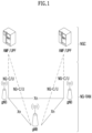
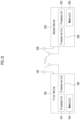
- FIG. 1 illustrates a structure of a wireless communication system to which the present disclosure may be applied.
- NG-RAN is configured with gNBs which provide a control plane (RRC) protocol end for a NG-RA(NG-Radio Access) user plane (i.e., a new AS(access stratum) sublayer/PDCP(Packet Data Convergence Protocol)/RLC(Radio Link Control)/MAC/PHY) and UE.
- RRC control plane
- the gNBs are interconnected through a Xn interface.
- the gNB in addition, is connected to an NGC(New Generation Core) through an NG interface.
- the gNB is connected to an AMF(Access and Mobility Management Function) through an N2 interface, and is connected to a UPF(User Plane Function) through an N3 interface.
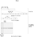
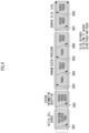
- FIG. 2 illustrates a frame structure in a wireless communication system to which the present disclosure may be applied.
- a NR system may support a plurality of numerologies.
- a numerology may be defined by a subcarrier spacing and a cyclic prefix (CP) overhead.
- CP cyclic prefix
- a plurality of subcarrier spacings may be derived by scaling a basic (reference) subcarrier spacing by an integer N (or, ⁇ ).
- N or, ⁇
- a used numerology may be selected independently from a frequency band.
- a variety of frame structures according to a plurality of numerologies may be supported in a NR system.
- NR supports a plurality of numerologies (or subcarrier spacings (SCS)) for supporting a variety of 5G services. For example, when a SCS is 15kHz, a wide area in traditional cellular bands is supported, and when a SCS is 30kHz/60kHz, dense-urban, lower latency and a wider carrier bandwidth are supported, and when a SCS is 60kHz or higher, a bandwidth wider than 24.25GHz is supported to overcome a phase noise.
- numerologies or subcarrier spacings (SCS)
- FR1, FR2 may be configured as in the following Table 2.
- FR2 may mean a millimeter wave (mmW).
- mmW millimeter wave
- ⁇ f max is 480 ⁇ 103 Hz and N f is 4096.
- T TA (N TA +N TA, offset ) T c than a corresponding downlink frame in a corresponding terminal starts.
- T TA (N TA +N TA, offset ) T c than a corresponding downlink frame in a corresponding terminal starts.
- slots are numbered in an increasing order of n s ⁇ ⁇ ⁇ 0, ..., N slot subframe, ⁇ -1 ⁇ in a subframe and are numbered in an increasing order of n s,f ⁇ ⁇ 0, ..., N slot frame, ⁇ -1 ⁇ in a radio frame.
- One slot is configured with N symb slot consecutive OFDM symbols and N symb slot is determined according to CP.
- a start of a slot n s ⁇ in a subframe is temporally arranged with a start of an OFDM symbol n s ⁇ N symb slot in the same subframe. All terminals may not perform transmission and reception at the same time, which means that all OFDM symbols of a downlink slot or an uplink slot may not be used.
- Table 3 represents the number of OFDM symbols per slot (N symb slot ), the number of slots per radio frame (N slot frame, ⁇ ) and the number of slots per subframe (N slot subframe, ⁇ ) in a normal CP and Table 4 represents the number of OFDM symbols per slot, the number of slots per radio frame and the number of slots per subframe in an extended CP.
- Table 3 ⁇ N symb slot N slot frame, ⁇ N slot subframe, ⁇ 0 14 10 1 1 14 20 2 2 14 40 4 3 14 80 8 4 14 160 16
- Table 4 ⁇ N symb slot N slot frame, ⁇ N slot subframe, ⁇ 2 12 40 4
- an antenna port a resource grid, a resource element, a resource block, a carrier part, etc. may be considered.
- the physical resources which may be considered in an NR system will be described in detail.
- an antenna port in relation to an antenna port, is defined so that a channel where a symbol in an antenna port is carried can be inferred from a channel where other symbol in the same antenna port is carried.
- a large-scale property of a channel where a symbol in one antenna port is carried may be inferred from a channel where a symbol in other antenna port is carried, it may be said that 2 antenna ports are in a QC/QCL(quasi co-located or quasi co-location) relationship.
- the large-scale property includes at least one of delay spread, doppler spread, frequency shift, average received power, received timing.
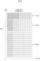
- FIG. 3 illustrates a resource grid in a wireless communication system to which the present disclosure may be applied.
- a resource grid is configured with N RB ⁇ N sc RB subcarriers in a frequency domain and one subframe is configured with 14 ⁇ 2 ⁇ OFDM symbols, but it is not limited thereto.
- a transmitted signal is described by OFDM symbols of 2 ⁇ N symb ( ⁇ ) and one or more resource grids configured with N RB ⁇ N sc RB subcarriers.
- N RB ⁇ ⁇ N RB max, ⁇ The N RB max, ⁇ represents a maximum transmission bandwidth, which may be different between an uplink and a downlink as well as between numerologies.
- one resource grid may be configured per ⁇ and antenna port p.
- Each element of a resource grid for ⁇ and an antenna port p is referred to as a resource element and is uniquely identified by an index pair (k, l').
- an index pair (k, l) is used.
- l 0,..., N symb ⁇ -1.
- a resource element (k, l') for ⁇ and an antenna port p corresponds to a complex value, a k, l' (p, ⁇ ) .
- indexes p and ⁇ may be dropped, whereupon a complex value may be a k, l' (p) or a k, l' .
- Point A plays a role as a common reference point of a resource block grid and is obtained as follows.
- Common resource blocks are numbered from 0 to the top in a frequency domain for a subcarrier spacing configuration ⁇ .
- the center of subcarrier 0 of common resource block 0 for a subcarrier spacing configuration ⁇ is identical to 'point A'.
- a relationship between a common resource block number n CRB ⁇ and a resource element (k, l) for a subcarrier spacing configuration ⁇ in a frequency domain is given as in the following Equation 1.
- n CRB ⁇ ⁇ k N sc RB ⁇
- Physical resource blocks are numbered from 0 to N BWP,i size, ⁇ -1 in a bandwidth part (BWP) and i is a number of a BWP.
- a relationship between a physical resource block n PRB and a common resource block n CRB in BWP i is given by the following Equation 2.
- N BWP,i start, ⁇ is a common resource block that a BWP starts relatively to common resource block 0.
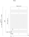
- FIG. 4 illustrates a physical resource block in a wireless communication system to which the present disclosure may be applied.
- FIG. 5 illustrates a slot structure in a wireless communication system to which the present disclosure may be applied.
- a slot includes a plurality of symbols in a time domain. For example, for a normal CP, one slot includes 7 symbols, but for an extended CP, one slot includes 6 symbols.
- a carrier includes a plurality of subcarriers in a frequency domain.
- An RB Resource Block
- a BWP(Bandwidth Part) is defined as a plurality of consecutive (physical) resource blocks in a frequency domain and may correspond to one numerology (e.g., an SCS, a CP length, etc.).
- a carrier may include a maximum N (e.g., 5) BWPs.
- a data communication may be performed through an activated BWP and only one BWP may be activated for one terminal.
- each element is referred to as a resource element (RE) and one complex symbol may be mapped.
- RE resource element
- a terminal operating in such a wideband CC may always operate turning on a radio frequency (FR) chip for the whole CC, terminal battery consumption may increase.
- FR radio frequency
- a different numerology e.g., a subcarrier spacing, etc.
- each terminal may have a different capability for the maximum bandwidth.
- a base station may indicate a terminal to operate only in a partial bandwidth, not in a full bandwidth of a wideband CC, and a corresponding partial bandwidth is defined as a bandwidth part (BWP) for convenience.
- a BWP may be configured with consecutive RBs on a frequency axis and may correspond to one numerology (e.g., a subcarrier spacing, a CP length, a slot/a mini-slot duration).
- a base station may configure a plurality of BWPs even in one CC configured to a terminal. For example, a BWP occupying a relatively small frequency domain may be configured in a PDCCH monitoring slot, and a PDSCH indicated by a PDCCH may be scheduled in a greater BWP.
- some terminals may be configured with other BWP for load balancing.
- some middle spectrums of a full bandwidth may be excluded and BWPs on both edges may be configured in the same slot.
- a base station may configure at least one DL/UL BWP to a terminal associated with a wideband CC.
- a base station may activate at least one DL/UL BWP of configured DL/UL BWP(s) at a specific time (by L1 signaling or MAC CE (Control Element) or RRC signaling, etc.).
- a base station may indicate switching to other configured DL/UL BWP (by L1 signaling or MAC CE or RRC signaling, etc.).
- a timer when a timer value is expired, it may be switched to a determined DL/UL BWP.
- an activated DL/UL BWP is defined as an active DL/UL BWP.
- a configuration on a DL/UL BWP may not be received when a terminal performs an initial access procedure or before a RRC connection is set up, so a DL/UL BWP which is assumed by a terminal under these situations is defined as an initial active DL/UL BWP.
- FIG. 6 illustrates physical channels used in a wireless communication system to which the present disclosure may be applied and a general signal transmission and reception method using them.
- a terminal receives information through a downlink from a base station and transmits information through an uplink to a base station.
- Information transmitted and received by a base station and a terminal includes data and a variety of control information and a variety of physical channels exist according to a type/a usage of information transmitted and received by them.
- a terminal When a terminal is turned on or newly enters a cell, it performs an initial cell search including synchronization with a base station or the like (S601).
- a terminal may synchronize with a base station by receiving a primary synchronization signal (PSS) and a secondary synchronization signal (SSS) from a base station and obtain information such as a cell identifier (ID), etc.
- PSS primary synchronization signal
- SSS secondary synchronization signal
- ID cell identifier
- a terminal may obtain broadcasting information in a cell by receiving a physical broadcast channel (PBCH) from a base station.
- PBCH physical broadcast channel
- a terminal may check out a downlink channel state by receiving a downlink reference signal (DL RS) at an initial cell search stage.
- DL RS downlink reference signal
- a terminal which completed an initial cell search may obtain more detailed system information by receiving a physical downlink control channel (PDCCH) and a physical downlink shared channel (PDSCH) according to information carried in the PDCCH (S602).
- PDCCH physical downlink control channel
- PDSCH physical downlink shared channel
- a terminal when a terminal accesses to a base station for the first time or does not have a radio resource for signal transmission, it may perform a random access (RACH) procedure to a base station (S603 to S606).
- RACH random access
- a terminal may transmit a specific sequence as a preamble through a physical random access channel (PRACH) (S603 and S605) and may receive a response message for a preamble through a PDCCH and a corresponding PDSCH (S604 and S606).
- PRACH physical random access channel
- a contention based RACH may additionally perform a contention resolution procedure.
- a terminal which performed the above-described procedure subsequently may perform PDCCH/PDSCH reception (S607) and PUSCH(Physical Uplink Shared Channel)/PUCCH(physical uplink control channel) transmission (S608) as a general uplink/downlink signal transmission procedure.
- a terminal receives downlink control information (DCI) through a PDCCH.
- DCI includes control information such as resource allocation information for a terminal and a format varies depending on its purpose of use.
- control information which is transmitted by a terminal to a base station through an uplink or is received by a terminal from a base station includes a downlink/uplink ACK/NACK(Acknowledgement/Non-Acknowledgement) signal, a CQI(Channel Quality Indicator), a PMI(Precoding Matrix Indicator), a RI(Rank Indicator), etc.
- a terminal may transmit control information of the above-described CQI/PMI/RI, etc. through a PUSCH and/or a PUCCH.
- Table 5 represents an example of a DCI format in an NR system.
- DCI Format Use 0_0 Scheduling of a PUSCH in one cell 0_1 Scheduling of one or multiple PUSCHs in one cell, or indication of cell group downlink feedback information to a UE 0_2 Scheduling of a PUSCH in one cell 1_0 Scheduling of a PDSCH in one DL cell 1_1 Scheduling of a PDSCH in one cell 1_2 Scheduling of a PDSCH in one cell
- DCI formats 0_0, 0_1 and 0_2 may include resource information (e.g., UL/SUL(Supplementary UL), frequency resource allocation, time resource allocation, frequency hopping, etc.), information related to a transport block(TB) (e.g., MCS(Modulation Coding and Scheme), a NDI(New Data Indicator), a RV(Redundancy Version), etc.), information related to a HARQ(Hybrid - Automatic Repeat and request) (e.g., a process number, a DAI(Downlink Assignment Index), PDSCH-HARQ feedback timing, etc.), information related to multiple antennas (e.g., DMRS sequence initialization information, an antenna port, a CSI request, etc.), power control information (e.g., PUSCH power control, etc.) related to scheduling of a PUSCH and control information included in each DCI format may be pre-defined.
- resource information e.g., UL/SUL(Sup
- DCI format 0_0 is used for scheduling of a PUSCH in one cell.
- Information included in DCI format 0_0 is CRC (cyclic redundancy check) scrambled by a C-RNTI(Cell Radio Network Temporary Identifier) or a CS-RNTI(Configured Scheduling RNTI) or a MCS-C-RNTI(Modulation Coding Scheme Cell RNTI) and transmitted.
- CRC cyclic redundancy check
- DCI format 0_1 is used to indicate scheduling of one or more PUSCHs or configure grant (CG) downlink feedback information to a terminal in one cell.
- Information included in DCI format 0_1 is CRC scrambled by a C-RNTI or a CS-RNTI or a SP-CSI-RNTI(Semi-Persistent CSI RNTI) or a MCS-C-RNTI and transmitted.
- DCI format 0_2 is used for scheduling of a PUSCH in one cell.
- Information included in DCI format 0_2 is CRC scrambled by a C-RNTI or a CS-RNTI or a SP-CSI-RNTI or a MCS-C-RNTI and transmitted.
- DCI formats 1_0, 1_1 and 1_2 may include resource information (e.g., frequency resource allocation, time resource allocation, VRB(virtual resource block)-PRB(physical resource block) mapping, etc.), information related to a transport block(TB)(e.g., MCS, NDI, RV, etc.), information related to a HARQ (e.g., a process number, DAI, PDSCH-HARQ feedback timing, etc.), information related to multiple antennas (e.g., an antenna port, a TCI(transmission configuration indicator), a SRS(sounding reference signal) request, etc.), information related to a PUCCH (e.g., PUCCH power control, a PUCCH resource indicator, etc.) related to scheduling of a PDSCH and control information included in each DCI format may be pre-defined.
- resource information e.g., frequency resource allocation, time resource allocation, VRB(virtual resource block)-PRB(physical resource block) mapping, etc.
- DCI format 1_0 is used for scheduling of a PDSCH in one DL cell.
- Information included in DCI format 1_0 is CRC scrambled by a C-RNTI or a CS-RNTI or a MCS-C-RNTI and transmitted.
- DCI format 1_1 is used for scheduling of a PDSCH in one cell.
- Information included in DCI format 1_1 is CRC scrambled by a C-RNTI or a CS-RNTI or a MCS-C-RNTI and transmitted.
- DCI format 1_2 is used for scheduling of a PDSCH in one cell.
- Information included in DCI format 1_2 is CRC scrambled by a C-RNTI or a CS-RNTI or a MCS-C-RNTI and transmitted.
- An antenna port is defined so that a channel where a symbol in an antenna port is transmitted can be inferred from a channel where other symbol in the same antenna port is transmitted.
- a property of a channel where a symbol in one antenna port is carried may be inferred from a channel where a symbol in other antenna port is carried, it may be said that 2 antenna ports are in a QC/QCL(quasi co-located or quasi co-location) relationship.
- the channel property includes at least one of delay spread, doppler spread, frequency/doppler shift, average received power, received timing/average delay, or a spatial RX parameter.
- a spatial Rx parameter means a spatial (Rx) channel property parameter such as an angle of arrival.
- a terminal may be configured at list of up to M TCI-State configurations in a higher layer parameter PDSCH-Config to decode a PDSCH according to a detected PDCCH having intended DCI for a corresponding terminal and a given serving cell.
- the M depends on UE capability.
- Each TCI-State includes a parameter for configuring a quasi co-location relationship between ports of one or two DL reference signals and a DM-RS of a PDSCH.
- a quasi co-location relationship is configured by a higher layer parameter qcl-Type1 for a first DL RS and qcl-Type2 for a second DL RS (if configured).
- a QCL type is not the same regardless of whether a reference is a same DL RS or a different DL RS.
- a quasi co-location type corresponding to each DL RS is given by a higher layer parameter qcl-Type of QCL-Info and may take one of the following values.
- a target antenna port is a specific NZP CSI-RS
- a terminal received such indication/configuration may receive a corresponding NZP CSI-RS by using a doppler, delay value measured in a QCL-TypeA TRS and apply a Rx beam used for receiving QCL-TypeD SSB to reception of a corresponding NZP CSI-RS.
- UE may receive an activation command by MAC CE signaling used to map up to 8 TCI states to a codepoint of a DCI field 'Transmission Configuration Indication'.
- a beam mismatch problem may occur according to a configured beam management cycle.
- a terminal moves or revolves or when a wireless channel environment is changed by the movement of a surrounding object (e.g., a beam is blocked to change a LoS (line-of sight) environment into a Non-LoS environment)
- the optimum DL/UL beam pair may be changed. Due to such a change, when tracking fails in a beam management process generally performed by a network indication, a beam failure event may be considered to occur. Whether such a beam failure event occurs may be determined by a terminal through reception quality of a downlink reference signal (RS).
- RS downlink reference signal
- a reporting message for such a situation or a message for a beam recovery request should be transmitted from a terminal.
- a base station which received such a beam failure recovery request message may perform beam recovery through a variety of processes such as beam RS transmission, beam reporting request, etc. for beam recovery. These series of beam recovery processes are referred to as beam failure recovery (BFR).
- BFR beam failure recovery
- a Rel-15 NR standardized a BFR (beam failure recovery) process for a primary cell (PCell) or a primary secondary cell (PScell) (the two are collectively referred to as a special cell (SpCell)) that a contention based PRACH resource always exists.
- a corresponding BFR procedure is configured as follows with a beam failure detection (BFD) process of a terminal, a BFRQ process, and a process in which a terminal monitors a response of a base station to a BFRQ.
- BFD beam failure detection
- FIG. 7 is a diagram which illustrates a beam failure recovery operation for a Pcell in a wireless communication system to which the present disclosure may be applied.
- quality is based on a hypothetical block error rate (BLER). In other words, it means a probability of a failure in demodulation of corresponding information when it is assumed that control information was transmitted to a corresponding PDCCH.
- BLER block error rate
- one or a plurality of search spaces for monitoring a PDCCH may be configured to a terminal.
- a beam may be differently configured per each search space. In this case, it means a case that all PDCCH beams for all search spaces fall below a BLER threshold.
- a method for a terminal to determine a BFD RS the following two methods are supported.
- a CORESET (control resource set) ID identifier
- a resource region where a PDCCH may be transmitted is configured in each search space.
- QCLed (Quasi Co-located) RS information for a spatial RX parameter e.g., a CSI-RS resource ID, a SSB ID
- a QCLed RS is indicated/configured by a TCI (transmit configuration information) indication in a NR standard.
- a QCLed RS for a spatial RX parameter means that a base station informs that a terminal equally uses (or may use) a beam used to receive a corresponding spatially QCLed RS (i.e., use the same spatial domain filter for reception) in receiving a corresponding PDCCH DMRS.
- a base station informs that a terminal equally uses (or may use) a beam used to receive a corresponding spatially QCLed RS (i.e., use the same spatial domain filter for reception) in receiving a corresponding PDCCH DMRS.
- it is a method of informing a terminal that transmission will be performed by applying the same transmission beam or a similar transmission beam (e.g., when a beam direction is same/similar, but a beam width is different) between spatially QCLed antenna ports.
- a terminal may determine (i.e., consider as the 'all PDCCH beams') as a BFD RS a QCLed (Quasi Co-located) RS for a spatial RX parameter configured to a CORESET for PDCCH reception.
- An explicit configuration for BFD RS(s) a base station may explicitly configure beam RS(s) to a terminal for the purpose (beam failure detection). In this case, corresponding configured beam RS(s) correspond to the 'all PDCCH beams' .
- a physical layer of a terminal informs a MAC sublayer that a beam failure instance (BFI) occurred.
- BFI beam failure instance
- a MAC sublayer of a terminal when as many BFIs as the certain number of times (e.g., a value of a higher layer parameter, beamFailureInstanceMaxCount) occur within a certain time (i.e., within a BFD timer), a beam failure is determined (considered) to occur and a relevant RACH operation is initiated.
- a MAC object operates as follows:
- a terminal may determine that a beam failure occurred and perform a beam failure recovery operation.
- a beam failure recovery operation a beam failure recovery request (BFRQ) operation based on a RACH procedure (i.e., a PRACH) may be performed.
- a corresponding BFRQ procedure is described in detail.
- a base station may configure a RS list (e.g., candidateBeamRSList) corresponding to candidate beams which may be substituted when a beam failure (BF) occurs through higher layer signaling (e.g., RRC) for a corresponding terminal.
- a RS list e.g., candidateBeamRSList
- dedicated PRACH resources may be configured for corresponding candidate beams.
- dedicated PRACH resources are non-contention based PRACH (also referred to as contention free PRACH) resources. If a terminal does not find a (proper) beam in a corresponding list, a terminal selects a contention based PRACH among preconfigured SSB resources and transmits it to a base station.
- a specific procedure is as follows.
- Step 1) A terminal finds a beam with more than a predetermined quality value (Q_in) among RSs configured by a base station as a candidate beam RS set.
- Q_in a predetermined quality value
- beam quality may be based on a RSRP.
- a RS beam set configured by the base station may include the following three cases.
- all beam RSs in a RS beam set may be configured with SSBs.
- all beam RSs in a RS beam set may be configured with CSI-RS resources.
- beam RSs in a RS beam set may be configured with SSBs and CSI-RS resources.
- Step 2) A terminal finds a beam with more than a predetermined quality value (Q_in) or more among SSBs (associated with a contention based PRACH resource).
- Step 3) A terminal selects any SSB among SSBs (associated with a contention based PRACH resource).
- a terminal transmits to a base station a preamble and a PRACH resource which is directly or indirectly associated and configured with a beam RS (CSI-RS or SSB) selected in the process.
- CSI-RS beam RS
- a terminal selects a preamble and a (contention free) PRACH resource associated with a SSB (i.e., QCLed (quasi-co-located) with respect to a spatial Rx parameter) designated to be receivable with the same Rx beam as a corresponding CSI-RS.
- a SSB i.e., QCLed (quasi-co-located) with respect to a spatial Rx parameter
- a response to the contention-free PRACH resource and preamble is transmitted to a PDCCH masked by a C-RNTI and a response is received in a search space (SS) which is separately configured by RRC for BFR.
- SS search space
- the search space is configured for a specific CORESET (for BFR).
- a search space and a CORESET (e.g., CORESET 0 or CORESET 1) configured for a general contention PRACH based random access process are reused as they are.
- the process may be performed until PRACH transmission reaches the preconfigured maximum number of times (N_max) or a configured timer (BFR timer) expires.
- a terminal stops contention free PRACH transmission, but may perform contention based PRACH transmission by a SSB selection until N_max is reached.
- Rel-15 NR standardized a PRACH based BFR process.
- it is applied only to a PCell or a PSCell due to a technical limit that any SCell may have no UL carrier in CA (carrier aggregation) and although there is a UL carrier, a contention based PRACH may not be configured.
- Such a limit has a limit that especially, when a SCell is operated in a high frequency band (e.g., 30GHz) while operating a PCell in a low frequency band (e.g., below 6GHz), BFR may not be supported in a high frequency band where BFR is actually needed. For this reason, standardization for BFR support on a SCell is performed in a Rel-16 NR MIMO work item.
- UL transmission to a corresponding SCell is impossible at least for a DL only SCell, so it is planned to configure (dedicated) PUCCH resource(s), which are used for informing a base station that SCell beam failure occurred, in a SpCell and use it to perform a BFRQ for a SCell.
- the PUCCH is referred to as a BFR-PUCCH.
- an object of a BFR-PRACH standardized in Rel-15 is to transmit 'occurrence of beam failure + new beam RS (set) information' together to a base station.
- an object of a BFR-PUCCH is to inform only 'occurrence of beam failure to SCell(s)'. And, to which SCell(s) beam failure occurred (e.g., CC index(es)), whether there is a new beam for corresponding SCell(s) and a corresponding beam RS ID when there is a new beam (and quality(s) (e.g., a RSRP or a SINR) of corresponding beam RS(s)) may be reported as a subsequent MAC-CE (or UCI).
- SCell(s) beam failure occurred e.g., CC index(es)
- quality(s) e.g., a RSRP or a SINR
- a subsequent beam report is not necessarily triggered all the time and it is possible to deactivate SCell(s) which are BFR configured for a corresponding terminal after a base station receives a BFR-PUCCH.
- a reason for such a design is because dozens of SCells may be associated with one PCell/PSCell and because from a viewpoint of a base station, there may be a lot of terminals sharing one PCell/PSCell UL, and considering even such a case, it is desirable to minimize the amount of UL resources reserved for a SCell BFRQ to each terminal in a PCell/PSCell.
- a CORESET Information Element (IE) is used to configure a time/frequency CORESET for searching for downlink control information.
- Table 6 illustrates a CORESET IE.
- the following table 7 is a table which describes a field in a CORESET IE.
- Description on a CORESET IE field cce-REG-MappingType Mapping of CCEs (control channel element) with REGs (resource element group) controlResourceSetId
- a value of 0 identifies a common CORESET (CORESET0, controlResourceSetZero) configured in a serving cell common configuration (ServingCellConfigCommon) or in a MIB (master information block) and is not used in this CORESET IE.
- a value of 1 to maxNrofControlResourceSets-1 identifies CORESETs configured by dedicated signaling or SIB1 (system information block 1).
- controlResourceSetId is unique among BWPs of a serving cell.
- duration Consecutive time duration of a CORESET in number of symbols (duration) frequencyDomainResources Frequency domain resources for a CORESET.
- Each bit corresponds to a group of 6 RBs grouped starting from a first RB group in a BWP.
- a first (leftmost/most significant) bit corresponds to a first RB group in a BWP, and so on.
- a bit set as 1 indicates that this RB group belongs to a frequency domain resource of this CORESET.
- a bit corresponding to a group of RBs which are not entirely included in a BWP where a CORESET is configured is set as 0.
- interleaverSize Interleaver-Size pdcch-DMRS-ScramblingID Initialize PDCCH DMRS Scrambling.
- UE applies a value of a physical cell identifier (physCellId) configured for this serving cell.
- precoderGranularity Precoder granularity in a frequency domain reg-BundleSize Resource element groups (REG) may be bundled to generate REG bundles. This parameter defines a size of such bundles.
- shiftIndex When this field is absent, UE applies a value of a physical cell identifier (physCellId) configured for this serving cell.
- tci-PresentInDCI This field indicates whether there is a TCI (transmission configuration indicator) field in DL-related DCI. When this field is absent, UE considers TCI to be absent/disabled.
- a network sets this field to be used for a CORESET used for cross carrier scheduling in a scheduling cell.
- tci-StatesPDCCH-ToAddList A subset of TCI states defined in a PDSCH configuration (pdsch-Config) included in a DL BWP to which a CORESET belongs and a downlink dedicated BWP (BWP-DownlinkDedicated) corresponding to a serving cell.
- NotSIB1-initialBWP This field is a field subject to conditional presence. When SIB1 is broadcast, this field is absent in a PDCCH common configuration (PDCCH-ConfigCommon) of a first BWP in SIB1 and a serving cell common configuration (ServingCellConfigCommon). Otherwise, it is optionally present.
- a CORESET identifier (ControlResourceSetId) IE is related to a short identifier (short identity) used to identify a CORESET in a serving cell.
- ControlResourceSetId 0 identifies ControlResourceSet#0 configured through a PBCH (MIB) and controlResourceSetZero (serving cell common configuration (ServingCellConfigCommon)).
- An ID space is used in BWPs of a serving cell.
- the number of CORESETs per BWP is limited to 3 (including a common CORESET and a UE-specific CORESET).
- Table 8 illustrates a ControlResourceSetId IE.
- a CORESET zero (ControlResourceSetZero) IE is used to configure CORESET#0 of a first BWP.
- Table 9 illustrates a ControlResourceSetZero IE.
- a coordinated multi point (CoMP) scheme refers to a scheme in which a plurality of base stations effectively control interference by exchanging (e.g., using an X2 interface) or utilizing channel information (e.g., RI/CQI/PMI/LI(layer indicator), etc.) fed back by a terminal and cooperatively transmitting to a terminal.
- a CoMP may be classified into joint transmission(JT), coordinated Scheduling(CS), coordinated Beamforming(CB), dynamic Point Selection(DPS), dynamic Point Blocking(DPB), etc.
- M-TRP transmission schemes that M TRPs transmit data to one terminal may be largely classified into i) eMBB M-TRP transmission, a scheme for improving a transfer rate, and ii) URLLC M-TRP transmission, a scheme for increasing a reception success rate and reducing latency.
- M-TRP transmission schemes may be classified into i) M-TRP transmission based on M-DCI(multiple DCI) that each TRP transmits different DCIs and ii) M-TRP transmission based on S-DCI(single DCI) that one TRP transmits DCI.
- M-DCI based M-TRP transmission all scheduling information on data transmitted by M TRPs should be delivered to a terminal through one DCI, it may be used in an environment of an ideal BackHaul (ideal BH) where dynamic cooperation between two TRPs is possible.
- scheme 3/4 is under discussion for standardization.
- scheme 4 means a scheme in which one TRP transmits a transport block(TB) in one slot and it has an effect to improve a probability of data reception through the same TB received from multiple TRPs in multiple slots.
- scheme 3 means a scheme in which one TRP transmits a TB through consecutive number of OFDM symbols (i.e., a symbol group) and TRPs may be configured to transmit the same TB through a different symbol group in one slot.
- UE may recognize PUSCH (or PUCCH) scheduled by DCI received in different control resource sets(CORESETs)(or CORESETs belonging to different CORESET groups) as PUSCH (or PUCCH) transmitted to different TRPs or may recognize PDSCH (or PDCCH) from different TRPs.
- the below-described method for UL transmission e.g., PUSCH/PUCCH
- PUSCH/PUCCH PUSCH/PUCCH
- an MTRP-URLLC may mean that the same TB (Transport Block) is transmitted using different layers/time/frequencies of M-TRPs.
- a UE configured with an MTRP-URLLC transmission method may be indicated with multiple TCI state(s) by DCI, and it may be assumed that data received using a QCL RS of each TCI state is the same TB.
- an MTRP-eMBB may mean that different TBs are transmitted using different layers/time/frequencies by M-TRPs.
- a UE configured with an MTRP-eMBB transmission method is indicated by several TCI state (s) by DCI, and it may be assumed that data received using a QCL RS of each TCI state are different TBs.
- a UE separates and uses an RNTI configured for an MTRP-URLLC purpose and an RNTI configured for an MTRP-eMBB purpose
- a CORESET group ID described/mentioned in the present disclosure may mean an index/identification information (e.g., an ID, etc.) for distinguishing a CORESET for each TRP/panel.
- a CORESET group may be a group/union of CORESET distinguished by an index/identification information (e.g., an ID)/the CORESET group ID, etc. for distinguishing a CORESET for each TRP/panel.
- a CORESET group ID may be specific index information defined in a CORESET configuration.
- a CORESET group may be configured/indicated/defined by an index defined in a CORESET configuration for each CORESET.
- a CORESET group ID may mean an index/identification information/an indicator, etc. for distinguishment/identification between CORESETs configured/associated with each TRP/panel.
- a CORESET group ID described/mentioned in the present disclosure may be expressed by being substituted with a specific index/specific identification information/a specific indicator for distinguishment/identification between CORESETs configured/associated with each TRP/panel.
- the CORESET group ID i.e., a specific index/specific identification information/a specific indicator for distinguishment/identification between CORESETs configured/associated with each TRP/panel may be configured/indicated to a terminal through higher layer signaling (e.g., RRC signaling)/L2 signaling (e.g., MAC-CE)/L1 signaling (e.g., DCI), etc.
- RRC signaling e.g., RRC signaling
- L2 signaling e.g., MAC-CE
- L1 signaling e.g., DCI
- uplink control information e.g., CSI, HARQ-A/N(ACK/NACK), SR(scheduling request)
- uplink physical channel resources e.g., PUCCH/PRACH/SRS resources
- HARQ A/N(process/retransmission) for PDSCH/PUSCH, etc. scheduled per each TRP/panel may be managed per corresponding CORESET group (i.e., per TRP/panel belonging to the same CORESET group).
- a higher layer parameter ControlResourceSet information element is used to configure a time/frequency control resource set (CORESET).
- the control resource set may be related to detection and reception of downlink control information.
- the ControlResourceSet IE may include a CORESET-related ID (e.g., controlResourceSetID) / an index of a CORESET pool for a CORESET (e.g., CORESETPoolIndex) / a time/frequency resource configuration of a CORESET / TCI information related to a CORESET, etc.
- an index of a CORESET pool (e.g., CORESETPoolIndex) may be set to 0 or 1.
- a CORESET group may correspond to a CORESET pool
- a CORESET group ID may correspond to a CORESET pool index (e.g., CORESETPoolIndex).
- NCJT Non-coherent joint transmission
- TP transmission points
- DMRS Demodulation Multiplexing Reference Signal
- a TP delivers data scheduling information through DCI to a terminal receiving NCJT.
- a scheme in which each TP participating in NCJT delivers scheduling information on data transmitted by itself through DCI is referred to as 'multi DCI based NCJT'.
- UE receives N DCI and N PDSCHs from N TPs.
- a scheme in which one representative TP delivers scheduling information on data transmitted by itself and data transmitted by a different TP (i.e., a TP participating in NCJT) through one DCI is referred to as 'single DCI based NCJT'.
- N TPs transmit one PDSCH, but each TP transmits only some layers of multiple layers included in one PDSCH. For example, when 4-layer data is transmitted, TP 1 may transmit 2 layers and TP 2 may transmit 2 remaining layers to UE.
- NCJT partially overlapped NCJT
- NCJT may be classified into fully overlapped NCJT that time frequency resources transmitted by each TP are fully overlapped and partially overlapped NCJT that only some time frequency resources are overlapped.
- data of both of TP 1 and TP 2 are transmitted in some time frequency resources and data of only one TP of TP 1 or TP 2 is transmitted in remaining time frequency resources.
- FIG. 8 illustrates a method of multiple TRPs transmission in a wireless communication system to which the present disclosure may be applied.
- a layer group may mean a predetermined layer set including one or more layers.
- the amount of transmitted resources increases due to the number of a plurality of layers and thereby a robust channel coding with a low coding rate may be used for a TB, and additionally, because a plurality of TRPs have different channels, it may be expected to improve reliability of a received signal based on a diversity gain.
- FIG. 8(b) an example that different CWs are transmitted through layer groups corresponding to different TRPs is shown.
- a TB corresponding to CW #1 and CW #2 in the drawing is identical to each other.
- CW #1 and CW #2 mean that the same TB is respectively transformed through channel coding, etc. into different CWs by different TRPs. Accordingly, it may be considered as an example that the same TB is repetitively transmitted.
- FIG. 8(b) it may have a disadvantage that a code rate corresponding to a TB is higher compared to FIG. 8(a) .
- it has an advantage that it may adjust a code rate by indicating a different RV (redundancy version) value or may adjust a modulation order of each CW for encoded bits generated from the same TB according to a channel environment.
- RV redundancy version
- probability of data reception of a terminal may be improved as the same TB is repetitively transmitted through a different layer group and each layer group is transmitted by a different TRP/panel. It is referred to as a SDM (Spatial Division Multiplexing) based M-TRP URLLC transmission method. Layers belonging to different layer groups are respectively transmitted through DMRS ports belonging to different DMRS CDM groups.
- the above-described contents related to multiple TRPs are described based on an SDM (spatial division multiplexing) method using different layers, but it may be naturally extended and applied to a FDM (frequency division multiplexing) method based on a different frequency domain resource (e.g., RB/PRB (set), etc.) and/or a TDM (time division multiplexing) method based on a different time domain resource (e.g., a slot, a symbol, a sub-symbol, etc.).
- FDM frequency division multiplexing
- a different frequency domain resource e.g., RB/PRB (set), etc.
- TDM time division multiplexing
- BFR Beam failure recovery
- '/' means 'and', 'or', or 'and/or' depending on the context.
- a specific BFD-RS set may explicitly / implicitly correspond to a specific TRP.
- a PUCCH resource related to a specific TRP may be interpreted as a PUCCH resource related to a specific BFD-RS set.
- an NBI-RS set for configuring a candidate beam for new beam identification may be TRP-specifically configured.
- an NBI-RS set associated with (corresponding to) each BFD-RS set may be configured.
- SpCell special cell
- a BFR MAC CE message format is being enhanced to carry a CC index where TRP-specific BF occurred, a BFD-RS set index where BF occurred, whether a new beam is found in an NBI-RS set corresponding to a BFD-RS set in which BF has occurred, (a new beam was found case) NBI-RS information, etc. (Refer to the agreement on Rel-17 M-TRP BM in Table 10 below)
- Table 10 illustrates Rel-17 M-TRP BM related agreement with respect to TRP-specific BFR.
- FFS value of N (e.g. fixed in specification, or UE capability)
- FFS number of BFD RSs across all BFD-RS sets per DL BWP (e.g. fixed maximum value or UE capability)
- FFS Association details Agreement BFRQ response - Support at least the same gNB response as in Rel.16 SCell BFR (i.e.
- PUCCH SR resource can be configured with 2 spatial relations Agreement
- a single MAC-CE is used at least for BFRQ for all TRPs in all CCs in a cell group, which includes - Indices of failed BFD-RS set (as an indication of failed TRP link) - Indices of CC containing the failed TRP link - An indicator whether a new candidate beam is identified in the NBI-RS set associat ed with the failed BFD-RS set, and an resource indicator representing the new candid ate beam (if identified) based on the number of NBI-RS resources in the corresponding BI-RS set.
- FFS Content of MAC-CE related to SpCell when transmitted on msg3, msgA - Note: MAC-CE signaling design details are up to RAN2 - The term "failed TRP link" is used here for discussion purposes only Agreement
- the maximum number of BFD-RS resources per set is a UE capability, including a p ossible candidate value of 1 in Rel.17.
- FFS value of X (determined in spec or UE capability)
- RACH-based transmission can be triggered on a SpCell at least in the following scenarios - Scenario 1: When beam failure is detected on all BFD-RS sets on the SpCell - FFS: other scenarios Scenario 2: at least one TRP fails on SpCell Scenario 3: at least one pre-defined TRP fails on SpCell Scenario 4: at least one TRP fails and no PUCCH-SR is configured, and no UL grant is available Scenario 5: If MAC-CE based reporting does not work (details FFS) Scenario 6: When no PUCCH-SR is configured Agreement To associate BFD-RS set k and NBI-RS set j - Alt-1: 1-to-1, fixed in spec - Whether NBI-RS configuration is mandatory is separate discussion Agreement For the case of all CORESETs with 1 activated TCI state per CORESET , after 28 symbols from receiving the BFR response, the QCL assumption of all CORESETs associated with CORESETPoolIndex k (k
- N is a natural number
- BFRQ beam failure recovery request
- a BFRQ of M-TRP BFR up to two PUCCH-SR resources in a cell group are supported.
- a BFRQ MAC-CE capable of transmitting failed CC index information, one new candidate beam (if discovered) for a failed TRP/CC, and whether a new candidate beam is discovered is supported. At least a single TRP failure indication is supported.
- a single MAC-CE is used for at least BFRQ for all TRPs in all CCs of a cell group, which includes:
- the maximum number of BFD-RS resources per set is UE capability including a possible candidate value 1 in Rel.17.
- RACH-based transmission may be triggered in an SpCell at least in the following scenario.
- SCS of 28 symbols is the smallest SCS of active DL BWP(s) of CC(s) with failed TRP link(s) reported in a BFR MAC CE and an active DL BWP for a responding receiving CC.
- CBRA is supported when at least all BFD-RS sets fail in an SPCell.
- an RLM-RS selection rule is reused.
- a UE triggers a PUCCH-SR resource / SR configuration associated with a failed BFD-RS set.
- a base station configures specific TRP-specific BFD-RS(s) through RRC signaling (i.e., when a plurality of BFD-RS sets including one or more BFD-RSs are configured)
- RRC signaling i.e., when a plurality of BFD-RS sets including one or more BFD-RSs are configured
- a terminal needs to monitor/detect beam failure for corresponding resource(s) (i.e., BFD-RS resource), or a terminal needs to monitor/detect for activated resource(s) (i.e., BFD-RS resource) only after a base station transmits/receives an activation MAC CE for TRP-specific BFD-RS(s) configured through RRC signaling by a base station.
- a terminal may perform monitor/detect for beam failure detection (BFD) (i.e., BFI count) only for RS(s) (equal to or less than UE capability N BFD of the terminal) activated through MAC CE signaling among BFD-RS(s) in a BFD-RS set configured by RRC signaling.
- BFD beam failure detection
- problem 1 may occur in which ambiguity occurs as to whether the corresponding BF corresponds to TRP-specific BF or cell-specific BF.
- a terminal has been configured with a plurality of (e.g., two) (explicit) BFD-RS sets (and/or BFD-RS (s) in the two BFD-RS set) in a specific CC/BWP, the terminal may expect that a plurality of (e.g., two) BFD-RS sets in the corresponding CC/BWP is simultaneously activated through a BFD-RS activation MAC CE message. And/or, such configuration/activation (i.e., when two BFD-RS sets are configured, two BFD-RS sets are simultaneously activated) may be mandatory for an operation between a base station and a terminal.
- a plurality of (e.g., two) (explicit) BFD-RS sets (and/or BFD-RS (s) in the two BFD-RS set) in a specific CC/BWP the terminal may expect that a plurality of (e.g., two) BFD-RS sets in the corresponding CC/BWP is simultaneously activate
- a terminal when a terminal is configured with a plurality of BFD-RS sets (and/or one or more BFD-RSs within a plurality of BFD-RS sets) for a specific CC/BWP, the terminal may expect that activation is indicated for all BFD-RS sets configured in the corresponding CC/BWP through a BFD-RS activation MAC CE message. And/or, an operation between a base station/terminal that all BFD-RS sets configured for a terminal in the corresponding CC/BWP as described above are activated together (simultaneously) through a BFD-RS activation MAC CE message may be mandatory.
- a terminal may perform BFD on the corresponding BFD-RS set only by the RRC configuration (i.e., it may be considered that all BFD-RSs in the BFD-RS set configured by RRC signaling are activated).
- a terminal may not perform BFD until some BFD-RS(s) (equal to or less than UE capability N BFD ) among RSs configured by RRC are activated (i.e., it may be considered that all BFD-RSs in the BFD-RS set configured by RRC signaling are deactivated), and the terminal may perform BFD on the activated BFD-RS(s) after receiving an activation MAC CE.
- BFD-RSs below the threshold are configured by RRC signaling in a specific BFD-RS set among two BFD-RS sets
- BFD-RSs above the threshold are configured by RRC signaling in another BFD-RS set
- a problem in which a terminal performs BFD on a specific BFD-RS set (BFD-RS set in which BFD-RSs below the threshold are configured by RRC signaling) and does not perform BFD on another BFD-RS set (BFD-RS in which BFD-RSs above the threshold is configured by RRC signaling) may occur.
- Proposal 2 for Problem 2 When a terminal has been configured with two BFD-RS sets in a specific CC/BWP, even if the number of BFD-RSs configured by RRC signaling in a specific BFD-RS set exceeds a specific threshold, the terminal may perform BFD (i.e., monitor/detect for BFD) on specific BFD-RS(s) among BFD-RSs configured by RRC signaling.
- the specific BFD-RS(s) may correspond to the number of RS(s) equal to or less than the threshold in ascending order from an RS having the lowest global index/local index among RSs (e.g., periodic CSI-RS) configured as the BFD-RS.
- a terminal may consider that all BFD-RSs in the corresponding BFD-RS set are activated and perform monitor/detect for BFD on the corresponding BFD-RS(s).
- a terminal may perform monitor/detect for BFD for as many RS(s) as the number of RS(s) equal to or less than the threshold in the corresponding BFD-RS set.
- a terminal may perform BFD (i.e., monitor/detect for BFD) in the same manner as in proposal 2 on the RRC-configured BFD-RS.
- BFD i.e., monitor/detect for BFD
- a terminal may update BFD-RS(s) for performing BFD in a specific BFD-RS set.
- a terminal may immediately perform TRP-specific BFD without ambiguity when receiving BFD-RSs for two BFD-RS sets by RRC signaling.
- a terminal when a terminal has been configured with a plurality of (e.g., two) BFD-RS sets in a specific CC/BWP, if the number of BFD-RSs configured by RRC signaling in a specific BFD-RS set(s) exceeds a specific threshold, the terminal may not perform BFD for the specific BFD-RS set(s). In addition, a terminal may not perform BFD on other BFD-RS set(s) in which the number of BFD-RSs configured by RRC signaling is less than or equal to the threshold, and may wait for reception of a BFD-RS activation MAC CE message from a base station.
- a terminal may not perform BFD on other BFD-RS set(s) in which the number of BFD-RSs configured by RRC signaling is less than or equal to the threshold, and may wait for reception of a BFD-RS activation MAC CE message from a base station.
- a terminal may consider that all BFD-RSs are deactivated for all BFD-RS sets.
- an activation MAC CE may indicate downselection (i.e., activation) only for BFD-RS set(s) in which the number of BFD-RSs configured by RRC signaling exceeds a specific threshold.
- a terminal receiving the MAC CE may understand/consider that BFD-RS(s) in the corresponding other BFD-RS set(s) (i.e., a BFD-RS set in which the number of BFD-RSs is less than or equal to the threshold) are automatically activated when the MAC CE signaling is activated (e.g., 3 ms after a terminal transmits A/N (acknowledgement/negative acknowledgment, ACK/NACK) for the corresponding MAC CE message).
- A/N acknowledgement/negative acknowledgment, ACK/NACK
- the number of BFD-RSs configured by RRC signaling in the plurality of BFD-RS sets is i) all equal to or less than a threshold or ii) all more than a threshold.
- a terminal may i) perform BFD on all of the plurality (e.g., two) BFD-RS sets or ii) may not perform BFD on all of the plurality (e.g., two) BFD-RS sets (and/or may wait for a BFD-RS activation MAC CE message without performing).
- the above-described BFD-RS activation/deactivation MAC CE may activate/deactivate some of BFD-RSs configured in each BFD-RS set among two BFD-RS sets in a specific CC/BWP.
- a terminal may update each BFD-RS set to perform BFD (for counting BFI).
- BFD for counting BFI
- an operation of activating specific BFD-RS(s) in the corresponding set and deactivating other BFD-RS(s) may be performed.
- Proposal 3 to be described later is described with respect to one of BFD-RS sets for convenience of description, even if a plurality of BFD-RS sets are configured by RRC signaling. That is, proposal 3, which will be described later, may be individually applied to all of a plurality of BFD-RS sets configured by RRC signaling.
- Proposal 3 for Problem 3 When a terminal receives a BFD-RS activation/deactivation MAC CE message for a specific BFD-RS set, for example, a terminal may stop a BFI count for the corresponding BFD-RS set and may resume the BFI count again from the time when MAC CE signaling is activated (e.g., 3 ms after a terminal transmits an A/N for the corresponding MAC CE message).
- the terminal may continue/persist the BFI count for one or more BFD-RSs updated (changed) by the MAC CE.
- the terminal may continue/persist a BFI count for the corresponding BFD-RS set.
- update i.e., change
- the BFI count is continued/persisted by performing update on the corresponding some BFD-RSs (i.e., for the changed BFD-RS) (e.g., from the time when MAC CE signaling is activated).
- a terminal may apply RS #3 as a target BFD-RS to the BFI count of RS #1 at the corresponding time 3, and may continuously count the BFI within a time window.
- a terminal may continuously perform the BFI count with the updated BFD-RS.
- a terminal may continue/persist a BFI count for the corresponding BFD-RS set.
- update i.e., change
- a BFI count may be continued/persisted as shown in the example below (e.g., from when MAC CE signaling is activated).
- a combination of BFD-RSs before and after update is as follows.
- the RS with the lowest global/local index in the BFD-RS set may be replaced with the RS with the lowest global/local index in the BFD-RS set after update, and the RS with the highest global/local index in the BFD-RS set may be replaced with the RS with the highest global/local index in the BFD-RS set after update.
- the BFD-RSs in the BFD-RS set may be updated (changed) so that an order of global/local indexes in a BFD-RS set before an update and an order of global/local indexes in a BFD-RS set after the update correspond (one-to-one).
- the first RS in a BFD-RS set may be replaced with the first RS in the BFD-RS set after the update
- the second RS in the BFD-RS set may be replaced with the second RS in the BFD-RS set after the update. That is, BFD-RSs in a BFD-RS set may be updated (changed) so that a configuration order in the BFD-RS set before an update and a configuration order in the BFD-RS set after the update correspond (one-to-one).
- a terminal may continuously perform the BFI count with the updated BFD-RSs.
- a terminal and a base station may perform a BFD and/or BFR operation by individually applying the proposals 1, 2, and 3, and A terminal and a base station may perform a BFD and/or BFR operation by applying a combination of at least one or more of the proposals 1, 2, and 3.
- FIG. 9 illustrates a signaling method for an uplink transmission/reception method for beam failure recovery according to an embodiment of the present disclosure.
- FIG. 9 illustrates signaling between a network (e.g., TRP 1, TRP 2) and a UE in a situation of multi-TRPs (multiple TRPs) (i.e., M-TRPs, or multiple cells, hereinafter, all TRPs may be replaced with a cell) that methods proposed in the present disclosure (e.g., proposal 1, proposal 2, proposal 3, any one or a combination of one or more detailed embodiments in the detailed embodiments for proposals 1 to 3) may be applied.
- a UE/a network is just an example, and may be applied by being substituted with a variety of devices.
- FIG. 9 is just for convenience of a description, and does not limit a scope of the present disclosure.
- some step(s) illustrated in FIG. 9 may be omitted depending on circumstances and/or configurations.
- a network may be one base station including a plurality of TRPs or may be one cell including a plurality of TRPs.
- an ideal/a non-ideal backhaul may be configured between TRP 1 and TRP 2 configuring a network.
- the following description is described based on a plurality of TRPs, but it may be equally extended and applied to transmission through a plurality of panels.
- an operation that a terminal receives a signal from TRP1/TRP2 may be interpreted/described (or may be an operation) as an operation that a terminal receives a signal from a network (through/with TRP1/2) and an operation that a terminal transmits a signal to TRP1/TRP2 may be interpreted/described (or may be an operation) as an operation that a terminal transmits a signal to a network (through/with TRP1/TRP2) or may be conversely interpreted/described.
- a UE receives configuration/DCI from a representative TRP (e.g., TRP 1) in an M-TRP situation (or cell, hereinafter all TRPs can be replaced by a cell/panel, or M-TRP can be assumed even when a plurality of CORESETs are configured from one TRP).
- TRP a representative TRP
- the representative TRP may be a TRP for transmitting/transporting a system information block (SIB) / paging / random access (RA) related signal to a UE.
- SIB system information block
- RA random access
- a UE may report information on the maximum number of configurable BFD-RSs (i.e., N BFD ) per BFD-RS set to a network through/using TRP 1 (and/or TRP 2) as UE capability.
- N BFD the maximum number of configurable BFD-RSs
- a UE may receive configuration information through/using TRP 1 (and/or TRP 2) from a Network (S901).
- the configuration information may include information related to network configuration (e.g., TRP configuration) / information related to M-TRP-based transmission/reception (e.g., resource allocation, etc.).
- the configuration information may be transmitted through higher layer signaling (e.g., RRC signaling, MAC-CE, etc.).
- the configuration information may include configuration information related to a BFD procedure and/or a BFR procedure described in the above-described proposed methods (e.g., proposal 1, proposal 2, proposal 3, any one or a combination of one or more detailed embodiments in the detailed embodiments for proposals 1 to 3).
- the configuration information may include information on a CORESET/CORESET group(s) related to each TRP (e.g., CORESET group related TCI state(s) configuration / CORESET group identifier (ID), etc.).
- the configuration information may include a CORESET configuration.
- the configuration information may include information on BFD RS(s)/BFD RS set(s) related to the BFD procedure, or, in some cases, BFD RS(s)/BFD RS set(s) may not be explicitly configured/indicated.
- the configuration information may include information on a plurality of reference signals (RSs) (i.e., a RS in which a QCL related to spatial reception parameter is configured or a QCL type D RS) for a spatial relation assumption (e.g., QCL relation) configured for a specific CORESET (/CORESET group).
- RSs reference signals
- the configuration information may include configuration information for a BFRQ resource related to the BFR procedure.
- the configuration information may include information on BFD RS(s)/BFD RS set(s) related to the BFD procedure related to each TRP (for a specific cell or cell group).
- the configuration information may include information on PUCCH resources related to the BFR procedure related to each TRP (for a specific cell or cell group) .
- the configuration information may include information on a first BFD RS set (including one or more RSs) corresponding to TRP 1 and a second BFD RS set (including one or more RSs) corresponding to TRP 2.
- the configuration information may not include explicit information on the first BFD RS set and the second BFD RS set.
- a UE may determine the first BFD RS set and the second BFD RS set, respectively, including a QCL (quasi colocation) RS for a spatial reception parameter set in CORESETs having a different control resource set (CORESET) pool index.
- the configuration information may include information on a first PUCCH resource for BFR corresponding to TRP 1 and a second PUCCH resource for BFR corresponding to TRP 2 for a TRP-specific BFR procedure.
- the configuration information may include information on a PRACH resource for BFR for a cell-specific BFR procedure.
- a UE may receive BFD/BFR related information through/using TRP 1 (and/or TRP 2) from a network through a MAC-CE and/or DCI (S902).
- TRP 1 and/or TRP 2
- DCI DCI
- a UE may receive information related to a BFD procedure and/or a BFR procedure through MAC-CE signaling and/or DCI.
- one or more BFD-RSs may be activated for each of the plurality of BFD-RS sets by control information for activation of a BFD RS (e.g., BFD-RS activation MAC CE).
- the control information for activation of the BFD RS may always indicate activation of all BFD RS sets (i.e., both the first BFD RS set and the second BFD RS set) configured (in a specific cell or cell group) for the terminal by the configuration information.
- one or more BFD-RSs may be deactivated for each of the plurality of BFD-RS sets by control information for deactivation of a BFD RS (e.g., BFD-RS deactivation MAC CE).
- control information for deactivation of a BFD RS e.g., BFD-RS deactivation MAC CE
- control information for activation of the BFD RS and the control information for deactivation of the BFD RS may be the same or may be defined separately.
- a UE may perform a BFD procedure with a network (through/using TRP 1 and/or TRP 2) (S903).
- a UE may perform a BFD procedure based on the above-described proposed methods (e.g., proposal 1, proposal 2, proposal 3, any one or a combination of one or more detailed embodiments in the detailed embodiments for proposals 1 to 3).
- a UE may perform a BFD procedure based on a BFD RS.
- a terminal may receive RSs included in each of a first BFD RS set (explicitly or implicitly configured) corresponding to a first TRP and/or a second BFD RS set (explicitly or implicitly configured) corresponding to a second TRP, and may assess radio link quality for the received RS.
- assessing the radio link quality may mean comparing a hypothetical BLER (or SINR, RSRP) for each RS with a threshold as described above.
- a terminal when a terminal is configured with a first BFD set (corresponding to a first TRP) and a second BFD set (corresponding to a second TRP) and when one or more BFD RSs are activated in each of the first BFD RS set and the second BFD RS set by control information for activation or the configuration information, a terminal may assess the radio link quality using the activated one or more BFD RSs.
- one or more BFD-RSs may be activated for each of the plurality of BFD-RS sets by control information for activation of a BFD RS (e.g., BFD-RS activation MAC CE).
- the control information for activation of the BFD RS always indicates activation of all BFD RS sets (i.e., both the first BFD RS set and the second BFD RS set) configured (in a specific cell or cell group) for a terminal by the configuration information.
- the specific number may be the maximum number of configurable BFD RSs per BFD RS set reported to the base station as a terminal capability.
- all BFD RSs in the first BFD RS set and the second BFD RS set may be considered as activated.
- all BFD RSs in the first BFD RS set and the second BFD RS set may be considered as deactivated.
- one or more BFD RSs may be activated in each of the first BFD RS set and the second BFD RS set by the control information for activation of the BFD RS.
- one or more specific BFD-RSs for the corresponding BFD-RS set may be considered as activated.
- the one or more specific BFD-RSs may be determined as a specific number of BFD-RSs in ascending order from the lowest index of the BFD-RS.
- a terminal may count a first BFI and a second BFI, respectively, according to assessment of radio link quality (when the radio link quality is worse than a predefined threshold, a BFI value is incremented by 1). And, when the count value for the first BFI and/or the count value for the second BFI reaches the maximum value, the terminal may determine that a first beam failure and/or a second beam failure is detected. That is, a terminal may individually assess radio link quality for each TRP, individually count a BFI for each TRP, and individually determine whether beam failure is detected for each TRP.
- a terminal may determine that beam failure has been detected for the corresponding TRP (i.e., for a specific BFD RS set).
- a terminal may determine that beam failure for the corresponding TRP (i.e., for the corresponding BFD RS set) has been detected.
- the one or more first BFD-RSs may be updated to one or more second BFD-RSs by the control information for activation of the BFD RS.
- a terminal may continue the BFI count for the one or more first BFD-RSs for the updated one or more second BFD-RSs.
- a UE may perform a BFR procedure with a Network (through/using TRP 1 and/or TRP 2) (S904).
- a UE may perform the BFR procedure based on the above-described proposed methods (e.g., proposal 1, proposal 2, proposal 3, any one or a combination of one or more detailed embodiments in the detailed embodiments for proposals 1 to 3).
- a terminal may individually determine detection of beam failure for each TRP.
- a BFR procedure may be performed for each TRP in which the beam failure is detected.
- a terminal may perform the uplink transmission (i.e., a BFR request or a link recovery request or a scheduling request for BFR) on a corresponding PUCCH resource among the first PUCCH resource (i.e., corresponding to a first TRP or corresponding to a first BFD RS set) and the second PUCCH resource (i.e., corresponding to a second TRP or corresponding to a second BFD RS set).
- a beam failure may be declared by a terminal having assessed radio link quality in the above methods, and the uplink transmission (i.e., a BFR request or a link recovery request or a scheduling request for BFR) may be performed.
- a network receiving the uplink transmission i.e., a BFR request or a link recovery request or a scheduling request for BFR
- FIG. 10 is a diagram illustrating an operation of a terminal in a method for uplink transmission for beam failure recovery according to an embodiment of the present disclosure.
- FIG. 10 an operation of a terminal based on the previously proposed methods (e.g., proposal 1, proposal 2, proposal 3, any one or a combination of one or more detailed embodiments in the detailed embodiments for proposals 1 to 3) is exemplified.
- the example of FIG. 10 is for convenience of description, and does not limit the scope of the present disclosure. Some step(s) illustrated in FIG. 10 may be omitted depending on circumstances and/or configurations.
- a terminal in FIG. 10 is only one example, and may be implemented as the device illustrated in FIG. 12 below.
- the processor 102/202 of FIG. 12 may control to transmit/receive a channel/signal/data/information, etc. using the transceiver 106/206, and may control to store a transmitted or received channel/signal/data/information, etc. may be controlled in the memory 104/204.
- FIG. 10 may be processed by one or more processors 102, 202 of FIG. 12 , and the operations of FIG. 10 may be stored in a memory (e.g., one or more memories 104, 204 of FIG. 12 ) in the form of instructions/programs (e.g., instruction, executable code) for driving at least one processor (e.g., 102 and 202) of FIG. 12 .
- a memory e.g., one or more memories 104, 204 of FIG. 12
- instructions/programs e.g., instruction, executable code
- a terminal may report information on the maximum number of configurable BFD-RSs (i.e., N BFD ) per BFD-RS set to a base station as UE capability.
- N BFD the maximum number of configurable BFD-RSs
- a terminal may receive configuration information related to BFR from a base station (S1001).
- the configuration information may include configuration information related to a BFD procedure and/or a BFR procedure described in the above-described proposed methods (e.g., proposal 1, proposal 2, proposal 3, any one or a combination of one or more detailed embodiments in the detailed embodiments for proposals 1 to 3).
- the configuration information may include information on a CORESET/CORESET group(s) related to each TRP (e.g., CORESET group related TCI state(s) configuration / CORESET group identifier (ID), etc.).
- the configuration information may include a CORESET configuration.
- the configuration information may include information on BFD RS(s)/BFD RS set(s) related to the BFD procedure, or, in some cases, BFD RS(s)/BFD RS set(s) may not be explicitly configured/indicated.
- the configuration information may include information on a plurality of reference signals (RSs) (i.e., a RS in which a QCL related to spatial reception parameter is configured or a QCL type D RS) for a spatial relation assumption (e.g., QCL relation) configured for a specific CORESET (/CORESET group).
- RSs reference signals
- the configuration information may include configuration information for a BFRQ resource related to the BFR procedure.
- the configuration information may include information on BFD RS(s)/BFD RS set(s) related to the BFD procedure related to each TRP (for a specific cell or cell group).
- the configuration information may include information on PUCCH resources related to the BFR procedure related to each TRP (for a specific cell or cell group) .
- the configuration information may include information on a first BFD RS set (including one or more RSs) corresponding to TRP 1 and a second BFD RS set (including one or more RSs) corresponding to TRP 2.
- the configuration information may not include explicit information on the first BFD RS set and the second BFD RS set.
- a UE may determine the first BFD RS set and the second BFD RS set, respectively, including a QCL (quasi colocation) RS for a spatial reception parameter set in CORESETs having a different CORESET pool index.
- the configuration information may include information on a first PUCCH resource for BFR corresponding to TRP 1 and a second PUCCH resource for BFR corresponding to TRP 2 for a TRP-specific BFR procedure.
- the configuration information may include information on a PRACH resource for BFR for a cell-specific BFR procedure.
- a terminal may receive information related to a BFD procedure and/or a BFR procedure from a base station through MAC-CE signaling and/or DCI.
- one or more BFD-RSs may be activated for each of the plurality of BFD-RS sets by control information for activation of a BFD RS (e.g., BFD-RS activation MAC CE).
- the control information for activation of the BFD RS may always indicate activation of all BFD RS sets (i.e., both the first BFD RS set and the second BFD RS set) configured (in a specific cell or cell group) for the terminal by the configuration information.
- one or more BFD-RSs may be deactivated for each of the plurality of BFD-RS sets by control information for deactivation of a BFD RS (e.g., BFD-RS deactivation MAC CE).
- control information for deactivation of a BFD RS e.g., BFD-RS deactivation MAC CE
- control information for activation of the BFD RS and the control information for deactivation of the BFD RS may be the same or may be defined separately.
- a terminal performs an assessment of radio link quality for at least one of a first BFD RS set and a second BFD RS set (S1002).
- an assessment of the radio link quality may be performed based on the above-described proposed methods (e.g., proposal 1, proposal 2, proposal 3, any one or a combination of one or more detailed embodiments in the detailed embodiments for proposals 1 to 3).
- a terminal may receive RSs included in each of a first BFD RS set (explicitly or implicitly configured) corresponding to a first TRP and/or a second BFD RS set (explicitly or implicitly configured) corresponding to a second TRP, and may assess radio link quality for the received RS.
- assessing the radio link quality may mean comparing a hypothetical BLER (or SINR, RSRP) for each RS with a threshold as described above.
- a terminal when a terminal is configured with a first BFD set (corresponding to a first TRP) and a second BFD set (corresponding to a second TRP) and when one or more BFD RSs are activated in each of the first BFD RS set and the second BFD RS set by control information for activation or the configuration information, a terminal may assess the radio link quality using the activated one or more BFD RSs.
- one or more BFD-RSs may be activated for each of the plurality of BFD-RS sets by control information for activation of a BFD RS (e.g., BFD-RS activation MAC CE).
- the control information for activation of the BFD RS always indicates activation of all BFD RS sets (i.e., both the first BFD RS set and the second BFD RS set) configured (in a specific cell or cell group) for a terminal by the configuration information.
- the specific number may be the maximum number of configurable BFD RSs per BFD RS set reported to the base station as a terminal capability.
- all BFD RSs in the first BFD RS set and the second BFD RS set may be considered as activated.
- all BFD RSs in the first BFD RS set and the second BFD RS set may be considered as deactivated.
- one or more BFD RSs may be activated in each of the first BFD RS set and the second BFD RS set by the control information for activation of the BFD RS.
- one or more specific BFD-RSs for the corresponding BFD-RS set may be considered as activated.
- the one or more specific BFD-RSs may be determined as a specific number of BFD-RSs in ascending order from the lowest index of the BFD-RS.
- a terminal Based on detection of at least one of a first beam failure for a first BFD RS set and a second beam failure for a second BFD RS set according to an assessment of radio link quality for at least one of the first BFD RS set and the second BFD RS set, a terminal performs uplink transmission for BFR to a base station (S1003).
- a terminal may perform a BFD procedure and a BFR procedure based on the above-described proposed methods (e.g., proposal 1, proposal 2, proposal 3, any one or a combination of one or more detailed embodiments in the detailed embodiments for proposals 1 to 3).
- proposed methods e.g., proposal 1, proposal 2, proposal 3, any one or a combination of one or more detailed embodiments in the detailed embodiments for proposals 1 to 3.
- a terminal may receive RSs included in each of a first BFD RS set (explicitly or implicitly configured) corresponding to a first TRP and/or a second BFD RS set (explicitly or implicitly configured) corresponding to a second TRP, and may assess radio link quality for the received RS.
- a terminal may count a first BFI and a second BFI, respectively, according to assessment of radio link quality (when the radio link quality is worse than a predefined threshold, a BFI value is incremented by 1). And, when the count value for the first BFI and/or the count value for the second BFI reaches the maximum value, the terminal may determine that a first beam failure and/or a second beam failure is detected.
- a terminal may individually assess radio link quality for each TRP, individually count a BFI for each TRP, and individually determine whether beam failure is detected for each TRP.
- a terminal may perform the uplink transmission (i.e., a BFR request or a link recovery request or a scheduling request for BFR) on a corresponding PUCCH resource among the first PUCCH resource and the second PUCCH resource.
- a terminal may determine that beam failure has been detected for the corresponding TRP (i.e., for a specific BFD RS set).
- a terminal may determine that beam failure for the corresponding TRP (i.e., for the corresponding BFD RS set) has been detected.
- the one or more first BFD-RSs may be updated to one or more second BFD-RSs by the control information for activation of the BFD RS.
- a terminal may continue the BFI count for the one or more first BFD-RSs for the updated one or more second BFD-RSs.
- a terminal may individually determine detection of beam failure for each TRP.
- a BFR procedure may be performed for each TRP in which the beam failure is detected.
- a terminal may perform the uplink transmission (i.e., a BFR request or a link recovery request or a scheduling request for BFR) on a corresponding PUCCH resource among the first PUCCH resource (i.e., corresponding to a first TRP or corresponding to a first BFD RS set) and the second PUCCH resource (i.e., corresponding to a second TRP or corresponding to a second BFD RS set).
- a terminal may receive DCI for PUSCH scheduling from a base station.
- a terminal may transmit a MAC-CE for BFR to a base station through a PUSCH.
- the MAC-CE for BFR may include at least one of an index of a cell in which beam failure is detected, information on whether a new beam is found, new beam information, and an index of a BFD RS set in which beam failure is detected.
- a beam failure may be declared by a terminal having assessed radio link quality in the above methods, and the uplink transmission (i.e., a BFR request or a link recovery request) may be performed.
- a base station receiving the uplink transmission i.e., a BFR request or a link recovery request
- FIG. 11 is a diagram illustrating an operation of a base station for a method of uplink transmission for beam failure recovery according to an embodiment of the present disclosure.
- FIG. 11 in FIG. 10 , an operation of a base station based on the previously proposed methods (e.g., proposal 1, proposal 2, proposal 3, any one or a combination of one or more detailed embodiments in the detailed embodiments for proposals 1 to 3) is exemplified.
- the example of FIG. 11 is for convenience of description, and does not limit the scope of the present disclosure. Some step(s) illustrated in FIG. 11 may be omitted depending on circumstances and/or configurations.
- a base station in FIG. 11 is only one example, and may be implemented as the device illustrated in FIG. 12 below.
- the processor 102/202 of FIG. 12 may control to transmit/receive a channel/signal/data/information, etc. using the transceiver 106/206, and may control to store a transmitted or received channel/signal/data/information, etc. may be controlled in the memory 104/204.
- FIG. 11 may be processed by one or more processors 102, 202 of FIG. 12 , and the operations of FIG. 11 may be stored in a memory (e.g., one or more memories 104, 204 of FIG. 12 ) in the form of instructions/programs (e.g., instruction, executable code) for driving at least one processor (e.g., 102 and 202) of FIG. 12 .
- a memory e.g., one or more memories 104, 204 of FIG. 12
- instructions/programs e.g., instruction, executable code
- a base station may receive information on the maximum number of configurable BFD-RSs (i.e., N BFD ) per BFD-RS set from a terminal as UE capability.
- N BFD the maximum number of configurable BFD-RSs
- a base station may transmit configuration information related to BFR to a terminal (S1101).
- the configuration information may include configuration information related to a BFD procedure and/or a BFR procedure described in the above-described proposed methods (e.g., proposal 1, proposal 2, proposal 3, any one or a combination of one or more detailed embodiments in the detailed embodiments for proposals 1 to 3).
- the configuration information may include information on a CORESET/CORESET group(s) related to each TRP (e.g., CORESET group related TCI state(s) configuration / CORESET group identifier (ID), etc.).
- the configuration information may include a CORESET configuration.
- the configuration information may include information on BFD RS(s)/BFD RS set(s) related to the BFD procedure, or, in some cases, BFD RS(s)/BFD RS set(s) may not be explicitly configured/indicated.
- the configuration information may include information on a plurality of reference signals (RSs) (i.e., a RS in which a QCL related to spatial reception parameter is configured or a QCL type D RS) for a spatial relation assumption (e.g., QCL relation) configured for a specific CORESET (/CORESET group).
- RSs reference signals
- the configuration information may include configuration information for a BFRQ resource related to the BFR procedure.
- the configuration information may include information on BFD RS(s)/BFD RS set(s) related to the BFD procedure related to each TRP (for a specific cell or cell group).
- the configuration information may include information on PUCCH resources related to the BFR procedure related to each TRP (for a specific cell or cell group) .
- the configuration information may include information on a first BFD RS set (including one or more RSs) corresponding to TRP 1 and a second BFD RS set (including one or more RSs) corresponding to TRP 2.
- the configuration information may not include explicit information on the first BFD RS set and the second BFD RS set.
- a UE may determine the first BFD RS set and the second BFD RS set, respectively, including a QCL (quasi colocation) RS for a spatial reception parameter set in CORESETs having a different CORESET pool index.
- the configuration information may include information on a first PUCCH resource for BFR corresponding to TRP 1 and a second PUCCH resource for BFR corresponding to TRP 2 for a TRP-specific BFR procedure.
- the configuration information may include information on a PRACH resource for BFR for a cell-specific BFR procedure.
- a base station may transmit information related to a BFD procedure and/or a BFR procedure to a terminal through MAC-CE signaling and/or DCI.
- one or more BFD-RSs may be activated for each of the plurality of BFD-RS sets by control information for activation of a BFD RS (e.g., BFD-RS activation MAC CE).
- the control information for activation of the BFD RS may always indicate activation of all BFD RS sets (i.e., both the first BFD RS set and the second BFD RS set) configured (in a specific cell or cell group) for the terminal by the configuration information.
- one or more BFD-RSs may be deactivated for each of the plurality of BFD-RS sets by control information for deactivation of a BFD RS (e.g., BFD-RS deactivation MAC CE).
- control information for deactivation of a BFD RS e.g., BFD-RS deactivation MAC CE
- control information for activation of the BFD RS and the control information for deactivation of the BFD RS may be the same or may be defined separately.
- a base station Based on detection of at least one of a first beam failure for a first BFD RS set and a second beam failure for a second BFD RS set according to an assessment of radio link quality for at least one of the first BFD RS set and the second BFD RS set, a base station receives uplink transmission for BFR from a terminal (S1102).
- the BFD procedure and the BFR procedure may be performed based on the above-described proposed methods (e.g., proposal 1, proposal 2, proposal 3, any one or a combination of one or more detailed embodiments in the detailed embodiments for proposals 1 to 3).
- a base station may transmit RSs included in each of a first BFD RS set (explicitly or implicitly configured) corresponding to a first TRP and/or a second BFD RS set (explicitly or implicitly configured) corresponding to a second TRP to a terminal, and radio link quality for the received RS may be assessed by the terminal.
- assessing the radio link quality may mean comparing a hypothetical BLER (or SINR, RSRP) for each RS with a threshold as described above.
- the radio link quality may be assess using the activated one or more BFD RSs by a terminal.
- one or more BFD-RSs may be activated for each of the plurality of BFD-RS sets by control information for activation of a BFD RS (e.g., BFD-RS activation MAC CE).
- the control information for activation of the BFD RS always indicates activation of all BFD RS sets (i.e., both the first BFD RS set and the second BFD RS set) configured (in a specific cell or cell group) for a terminal by the configuration information.
- the specific number may be the maximum number of configurable BFD RSs per BFD RS set reported to the base station as a terminal capability.
- all BFD RSs in the first BFD RS set and the second BFD RS set may be considered as activated.
- all BFD RSs in the first BFD RS set and the second BFD RS set may be considered as deactivated.
- one or more BFD RSs may be activated in each of the first BFD RS set and the second BFD RS set by the control information for activation of the BFD RS.
- one or more specific BFD-RSs for the corresponding BFD-RS set may be considered as activated.
- the one or more specific BFD-RSs may be determined as a specific number of BFD-RSs in ascending order from the lowest index of the BFD-RS.
- a first BFI and a second BFI may be counted, respectively, according to an assessment of radio link quality by a terminal (when the radio link quality is worse than a predefined threshold, a BFI value is incremented by 1). And, when the count value for the first BFI and/or the count value for the second BFI reaches the maximum value, it may be determined that a first beam failure and/or a second beam failure is detected by a terminal. That is, radio link quality is individually assessed for each TRP by a terminal, a BFI is individually counted for each TRP by a terminal, and whether beam failure is detected by a terminal may be individually determined for each TRP.
- a BFI for a specific TRP i.e., for a specific BFD RS set
- a plurality of BFD RSs in a BFD RS set for a specific TRP are configured (or activated as the proposals)
- the BFI for all configured/activated BFD RSs reaches the maximum value
- it may be determined that beam failure for the corresponding TRP i.e., for the corresponding BFD RS set
- the one or more first BFD-RSs may be updated to one or more second BFD-RSs by the control information for activation of the BFD RS.
- a terminal may continue the BFI count for the one or more first BFD-RSs for the updated one or more second BFD-RSs.
- a terminal may individually determine detection of beam failure for each TRP.
- a BFR procedure may be performed for each TRP in which the beam failure is detected.
- a base station may receive the uplink transmission (i.e., a BFR request or a link recovery request or a scheduling request for BFR) on a corresponding PUCCH resource among the first PUCCH resource and the second PUCCH resource.
- a base station may transmit DCI for PUSCH scheduling to a terminal.
- a base station may receive a MAC-CE for BFR from a terminal through a PUSCH.
- the MAC-CE for BFR may include at least one of an index of a cell in which beam failure is detected, information on whether a new beam is found, new beam information, and an index of a BFD RS set in which beam failure is detected.
- a beam failure may be declared by a terminal having assessed radio link quality in the above methods, and the uplink transmission (i.e., a BFR request or a link recovery request) may be performed.
- a base station receiving the uplink transmission i.e., a BFR request or a link recovery request
- FIG. 12 is a diagram which illustrates a block diagram of a wireless communication device according to an embodiment of the present disclosure.
- a first wireless device 100 and a second wireless device 200 may transmit and receive a wireless signal through a variety of radio access technologies (e.g., LTE, NR).
- radio access technologies e.g., LTE, NR.
- a first wireless device 100 may include one or more processors 102 and one or more memories 104 and may additionally include one or more transceivers 106 and/or one or more antennas 108.
- a processor 102 may control a memory 104 and/or a transceiver 106 and may be configured to implement description, functions, procedures, proposals, methods and/or operation flow charts disclosed in the present disclosure.
- a processor 102 may transmit a wireless signal including first information/signal through a transceiver 106 after generating first information/signal by processing information in a memory 104.
- a processor 102 may receive a wireless signal including second information/signal through a transceiver 106 and then store information obtained by signal processing of second information/signal in a memory 104.
- a memory 104 may be connected to a processor 102 and may store a variety of information related to an operation of a processor 102.
- a memory 104 may store a software code including commands for performing all or part of processes controlled by a processor 102 or for performing description, functions, procedures, proposals, methods and/or operation flow charts disclosed in the present disclosure.
- a processor 102 and a memory 104 may be part of a communication modem/circuit/chip designed to implement a wireless communication technology (e.g., LTE, NR).
- a transceiver 106 may be connected to a processor 102 and may transmit and/or receive a wireless signal through one or more antennas 108.
- a transceiver 106 may include a transmitter and/or a receiver.
- a transceiver 106 may be used together with a RF (Radio Frequency) unit.
- a wireless device may mean a communication modem/circuit/chip.
- a second wireless device 200 may include one or more processors 202 and one or more memories 204 and may additionally include one or more transceivers 206 and/or one or more antennas 208.
- a processor 202 may control a memory 204 and/or a transceiver 206 and may be configured to implement description, functions, procedures, proposals, methods and/or operation flows charts disclosed in the present disclosure.
- a processor 202 may generate third information/signal by processing information in a memory 204, and then transmit a wireless signal including third information/signal through a transceiver 206.
- a processor 202 may receive a wireless signal including fourth information/signal through a transceiver 206, and then store information obtained by signal processing of fourth information/signal in a memory 204.
- a memory 204 may be connected to a processor 202 and may store a variety of information related to an operation of a processor 202.
- a memory 204 may store a software code including commands for performing all or part of processes controlled by a processor 202 or for performing description, functions, procedures, proposals, methods and/or operation flow charts disclosed in the present disclosure.
- a processor 202 and a memory 204 may be part of a communication modem/circuit/chip designed to implement a wireless communication technology (e.g., LTE, NR).
- a transceiver 206 may be connected to a processor 202 and may transmit and/or receive a wireless signal through one or more antennas 208.
- a transceiver 206 may include a transmitter and/or a receiver.
- a transceiver 206 may be used together with a RF unit.
- a wireless device may mean a communication modem/circuit/chip.
- one or more protocol layers may be implemented by one or more processors 102, 202.
- one or more processors 102, 202 may implement one or more layers (e.g., a functional layer such as PHY, MAC, RLC, PDCP, RRC, SDAP).
- One or more processors 102, 202 may generate one or more PDUs (Protocol Data Unit) and/or one or more SDUs (Service Data Unit) according to description, functions, procedures, proposals, methods and/or operation flow charts included in the present disclosure.
- PDUs Protocol Data Unit
- SDUs Service Data Unit
- One or more processors 102, 202 may generate a message, control information, data or information according to description, functions, procedures, proposals, methods and/or operation flow charts disclosed in the present disclosure.
- One or more processors 102, 202 may generate a signal (e.g., a baseband signal) including a PDU, a SDU, a message, control information, data or information according to functions, procedures, proposals and/or methods disclosed in the present disclosure to provide it to one or more transceivers 106, 206.
- a signal e.g., a baseband signal
- One or more processors 102, 202 may receive a signal (e.g., a baseband signal) from one or more transceivers 106, 206 and obtain a PDU, a SDU, a message, control information, data or information according to description, functions, procedures, proposals, methods and/or operation flow charts disclosed in the present disclosure.
- a signal e.g., a baseband signal
- One or more processors 102, 202 may be referred to as a controller, a micro controller, a micro processor or a micro computer.
- One or more processors 102, 202 may be implemented by a hardware, a firmware, a software, or their combination.
- one or more ASICs Application Specific Integrated Circuit
- one or more DSPs Digital Signal Processor
- one or more DSPDs Digital Signal Processing Device
- one or more PLDs PROgrammable Logic Device
- FPGAs Field Programmable Gate Arrays
- Description, functions, procedures, proposals, methods and/or operation flow charts disclosed in the present disclosure may be implemented by using a firmware or a software and a firmware or a software may be implemented to include a module, a procedure, a function, etc.
- a firmware or a software configured to perform description, functions, procedures, proposals, methods and/or operation flow charts disclosed in the present disclosure may be included in one or more processors 102, 202 or may be stored in one or more memories 104, 204 and driven by one or more processors 102, 202.
- Description, functions, procedures, proposals, methods and/or operation flow charts disclosed in the present disclosure may be implemented by using a firmware or a software in a form of a code, a command and/or a set of commands.
- One or more memories 104, 204 may be connected to one or more processors 102, 202 and may store data, a signal, a message, information, a program, a code, an instruction and/or a command in various forms.
- One or more memories 104, 204 may be configured with ROM, RAM, EPROM, a flash memory, a hard drive, a register, a cash memory, a computer readable storage medium and/or their combination.
- One or more memories 104, 204 may be positioned inside and/or outside one or more processors 102, 202.
- one or more memories 104, 204 may be connected to one or more processors 102, 202 through a variety of technologies such as a wire or wireless connection.
- One or more transceivers 106, 206 may transmit user data, control information, a wireless signal/channel, etc. mentioned in methods and/or operation flow charts, etc. of the present disclosure to one or more other devices.
- One or more transceivers 106, 206 may receiver user data, control information, a wireless signal/channel, etc. mentioned in description, functions, procedures, proposals, methods and/or operation flow charts, etc. disclosed in the present disclosure from one or more other devices.
- one or more transceivers 106, 206 may be connected to one or more processors 102, 202 and may transmit and receive a wireless signal.
- one or more processors 102, 202 may control one or more transceivers 106, 206 to transmit user data, control information or a wireless signal to one or more other devices.
- one or more processors 102, 202 may control one or more transceivers 106, 206 to receive user data, control information or a wireless signal from one or more other devices.
- one or more transceivers 106, 206 may be connected to one or more antennas 108, 208 and one or more transceivers 106, 206 may be configured to transmit and receive user data, control information, a wireless signal/channel, etc. mentioned in description, functions, procedures, proposals, methods and/or operation flow charts, etc.
- one or more antennas may be a plurality of physical antennas or a plurality of logical antennas (e.g., an antenna port).
- One or more transceivers 106, 206 may convert a received wireless signal/channel, etc. into a baseband signal from a RF band signal to process received user data, control information, wireless signal/channel, etc. by using one or more processors 102, 202.
- One or more transceivers 106, 206 may convert user data, control information, a wireless signal/channel, etc. which are processed by using one or more processors 102, 202 from a baseband signal to a RF band signal.
- one or more transceivers 106, 206 may include an (analogue) oscillator and/or a filter.
- Embodiments described above are that elements and features of the present disclosure are combined in a predetermined form. Each element or feature should be considered to be optional unless otherwise explicitly mentioned. Each element or feature may be implemented in a form that it is not combined with other element or feature.
- an embodiment of the present disclosure may include combining a part of elements and/or features. An order of operations described in embodiments of the present disclosure may be changed. Some elements or features of one embodiment may be included in other embodiment or may be substituted with a corresponding element or a feature of other embodiment. It is clear that an embodiment may include combining claims without an explicit dependency relationship in claims or may be included as a new claim by amendment after application.
- a scope of the present disclosure includes software or machine-executable commands (e.g., an operating system, an application, a firmware, a program, etc.) which execute an operation according to a method of various embodiments in a device or a computer and a non-transitory computer-readable medium that such a software or a command, etc. are stored and are executable in a device or a computer.
- a command which may be used to program a processing system performing a feature described in the present disclosure may be stored in a storage medium or a computer-readable storage medium and a feature described in the present disclosure may be implemented by using a computer program product including such a storage medium.
- a storage medium may include a high-speed random-access memory such as DRAM, SRAM, DDR RAM or other random-access solid state memory device, but it is not limited thereto, and it may include a nonvolatile memory such as one or more magnetic disk storage devices, optical disk storage devices, flash memory devices or other nonvolatile solid state storage devices.
- a memory optionally includes one or more storage devices positioned remotely from processor(s).
- a memory or alternatively, nonvolatile memory device(s) in a memory include a non-transitory computer-readable storage medium.
- a feature described in the present disclosure may be stored in any one of machinereadable mediums to control a hardware of a processing system and may be integrated into a software and/or a firmware which allows a processing system to interact with other mechanism utilizing a result from an embodiment of the present disclosure.
- a software or a firmware may include an application code, a device driver, an operating system and an execution environment/container, but it is not limited thereto.
- a wireless communication technology implemented in a wireless device 100, 200 of the present disclosure may include Narrowband Internet of Things for a low-power communication as well as LTE, NR and 6G.
- an NB-IoT technology may be an example of a LPWAN(Low Power Wide Area Network) technology, may be implemented in a standard of LTE Cat NB1 and/or LTE Cat NB2, etc. and is not limited to the above-described name.
- a wireless communication technology implemented in a wireless device 100, 200 of the present disclosure may perform a communication based on a LTE-M technology.
- a LTE-M technology may be an example of a LPWAN technology and may be referred to a variety of names such as an eMTC (enhanced Machine Type Communication), etc.
- an LTE-M technology may be implemented in at least any one of various standards including 1) LTE CAT 0, 2) LTE Cat M1, 3) LTE Cat M2, 4) LTE non-BL (non-Bandwidth Limited), 5) LTE-MTC, 6) LTE Machine Type Communication, and/or 7) LTE M and so on and it is not limited to the above-described name.
- a wireless communication technology implemented in a wireless device 100, 200 of the present disclosure may include at least any one of a ZigBee, a Bluetooth and a low power wide area network (LPWAN) considering a low-power communication and it is not limited to the above-described name.
- a ZigBee technology may generate PAN(personal area networks) related to a small/low-power digital communication based on a variety of standards such as IEEE 802.15.4, etc. and may be referred to as a variety of names.
- a method proposed by the present disclosure is mainly described based on an example applied to 3GPP LTE/LTE-A, 5G system, but may be applied to various wireless communication systems other than the 3GPP LTE/LTE-A, 5G system.
Applications Claiming Priority (1)
| Application Number | Priority Date | Filing Date | Title |
|---|---|---|---|
| KR20220049397 | 2022-04-21 |
Publications (1)
| Publication Number | Publication Date |
|---|---|
| EP4266593A1 true EP4266593A1 (fr) | 2023-10-25 |
Family
ID=83903392
Family Applications (1)
| Application Number | Title | Priority Date | Filing Date |
|---|---|---|---|
| EP22202180.0A Pending EP4266593A1 (fr) | 2022-04-21 | 2022-10-18 | Procédé et appareil d'émission et de réception de liaison montante dans un système de communication sans fil |
Country Status (5)
| Country | Link |
|---|---|
| US (1) | US20230345568A1 (fr) |
| EP (1) | EP4266593A1 (fr) |
| JP (1) | JP2023160711A (fr) |
| KR (1) | KR20230150179A (fr) |
| CN (1) | CN116939849A (fr) |
Citations (1)
| Publication number | Priority date | Publication date | Assignee | Title |
|---|---|---|---|---|
| US20220109489A1 (en) * | 2020-10-05 | 2022-04-07 | Samsung Electronics Co., Ltd. | Method and apparatus for beam failure recovery in a wireless communication system |
-
2022
- 2022-10-06 KR KR1020220127693A patent/KR20230150179A/ko unknown
- 2022-10-18 EP EP22202180.0A patent/EP4266593A1/fr active Pending
- 2022-10-25 US US17/973,185 patent/US20230345568A1/en active Pending
- 2022-10-26 JP JP2022171397A patent/JP2023160711A/ja active Pending
- 2022-10-26 CN CN202211316030.4A patent/CN116939849A/zh active Pending
Patent Citations (1)
| Publication number | Priority date | Publication date | Assignee | Title |
|---|---|---|---|---|
| US20220109489A1 (en) * | 2020-10-05 | 2022-04-07 | Samsung Electronics Co., Ltd. | Method and apparatus for beam failure recovery in a wireless communication system |
Non-Patent Citations (3)
| Title |
|---|
| 3GPP NR, TS 38.211 |
| CATT: "Beam management enhancements for multi-TRP", vol. RAN WG1, no. e-Meeting; 20210519 - 20210527, 12 May 2021 (2021-05-12), XP052010809, Retrieved from the Internet <URL:https://ftp.3gpp.org/tsg_ran/WG1_RL1/TSGR1_105-e/Docs/R1-2104486.zip R1-2104486.docx> [retrieved on 20210512] * |
| NOKIA ET AL: "Enhancements on Beam Management for Multi-TRP", vol. RAN WG1, no. e-Meeting; 20210519 - 20210527, 11 May 2021 (2021-05-11), XP052006333, Retrieved from the Internet <URL:https://ftp.3gpp.org/tsg_ran/WG1_RL1/TSGR1_105-e/Docs/R1-2105275.zip R1-2105275_Enhancements on Beam Management.docx> [retrieved on 20210511] * |
Also Published As
| Publication number | Publication date |
|---|---|
| CN116939849A (zh) | 2023-10-24 |
| KR20230150179A (ko) | 2023-10-30 |
| US20230345568A1 (en) | 2023-10-26 |
| JP2023160711A (ja) | 2023-11-02 |
Similar Documents
| Publication | Publication Date | Title |
|---|---|---|
| US20230112271A1 (en) | Method and device for transmitting/receiving downlink control information in wireless communication system | |
| US20230073095A1 (en) | Method and apparatus for transmitting or receiving downlink channel from multiple transmission/reception points in wireless communication system | |
| EP4120581A1 (fr) | Procédé et dispositif d'évaluation de qualité de liaison radio dans un système de communication sans fil | |
| US11864206B2 (en) | Method and device for transmitting/receiving downlink channel from multiple transmission/reception points in wireless communication system | |
| US11963249B2 (en) | Beam failure recovery method and apparatus in wireless communication system | |
| US20230156740A1 (en) | Method and device for transmitting and receiving pdcch in wireless communication system | |
| EP4171150A1 (fr) | Procédé et appareil d'émission et de réception de liaison montante dans un système de communication sans fil | |
| US20230141397A1 (en) | Method and apparatus for transmitting and receiving channel state information in wireless communication system | |
| US20230119439A1 (en) | Method and device for transmission/reception based on time unit group in wireless communication system | |
| EP4123919A1 (fr) | Procédé et dispositif destinés à la transmission/réception de signal sur la base de paramètres spatiaux dans un système de communication sans fil | |
| US11877166B2 (en) | Method and device for recovering beam failure in wireless communication system | |
| EP4329210A1 (fr) | Procédé et dispositif de transmission et de réception de liaison montante dans un système de communication sans fil | |
| EP4283898A1 (fr) | Procédé et dispositif de transmission/réception en liaison montante dans un système de communication sans fil | |
| EP4280471A1 (fr) | Procédé et dispositif d'application d'un paramètre spatial dans un système de communication sans fil | |
| US20230224726A1 (en) | Method and device for transmission and reception based on default spatial parameter in wireless communication system | |
| US20230354347A1 (en) | Method and apparatus for transmitting and receiving data in wireless communication system | |
| US20230239114A1 (en) | Method and device for transmitting/receiving csi-rs in wireless communication system | |
| EP4131796A1 (fr) | Procédé et appareil de transmission ou de réception en liaison montante d'après un paramètre spécial dans un système de communication sans fil | |
| EP4266593A1 (fr) | Procédé et appareil d'émission et de réception de liaison montante dans un système de communication sans fil | |
| EP4318962A1 (fr) | Procédé et dispositif de transmission et de réception en liaison montante dans un système de communication sans fil | |
| EP4270809A1 (fr) | Procédé et dispositif permettant d'effectuer une reprise après défaillance de faisceau dans un système de communication sans fil | |
| US11864177B2 (en) | Method for performing beam failure recovery procedure in wireless communication system and device therefor | |
| US20230155736A1 (en) | Method and device for pdsch transmission/reception in wireless communication system | |
| EP4270844A1 (fr) | Procédé et appareil de transmission en liaison montante dans un système de communication sans fil | |
| KR20240027692A (ko) | 무선 통신 시스템에서 빔 복구를 수행하는 방법 및 장치 |
Legal Events
| Date | Code | Title | Description |
|---|---|---|---|
| STAA | Information on the status of an ep patent application or granted ep patent |
Free format text: STATUS: THE APPLICATION HAS BEEN PUBLISHED |
|
| PUAI | Public reference made under article 153(3) epc to a published international application that has entered the european phase |
Free format text: ORIGINAL CODE: 0009012 |
|
| AK | Designated contracting states |
Kind code of ref document: A1 Designated state(s): AL AT BE BG CH CY CZ DE DK EE ES FI FR GB GR HR HU IE IS IT LI LT LU LV MC ME MK MT NL NO PL PT RO RS SE SI SK SM TR |
|
| STAA | Information on the status of an ep patent application or granted ep patent |
Free format text: STATUS: REQUEST FOR EXAMINATION WAS MADE |
|
| 17P | Request for examination filed |
Effective date: 20231102 |
|
| RBV | Designated contracting states (corrected) |
Designated state(s): AL AT BE BG CH CY CZ DE DK EE ES FI FR GB GR HR HU IE IS IT LI LT LU LV MC ME MK MT NL NO PL PT RO RS SE SI SK SM TR |