EP4266520A1 - Grid shield - Google Patents
Grid shield Download PDFInfo
- Publication number
- EP4266520A1 EP4266520A1 EP23169227.8A EP23169227A EP4266520A1 EP 4266520 A1 EP4266520 A1 EP 4266520A1 EP 23169227 A EP23169227 A EP 23169227A EP 4266520 A1 EP4266520 A1 EP 4266520A1
- Authority
- EP
- European Patent Office
- Prior art keywords
- grid
- phase
- bus
- voltage
- root cause
- Prior art date
- Legal status (The legal status is an assumption and is not a legal conclusion. Google has not performed a legal analysis and makes no representation as to the accuracy of the status listed.)
- Pending
Links
Images



Classifications
-
- H—ELECTRICITY
- H02—GENERATION; CONVERSION OR DISTRIBUTION OF ELECTRIC POWER
- H02J—ELECTRIC POWER NETWORKS; CIRCUIT ARRANGEMENTS OR SYSTEMS FOR SUPPLYING OR DISTRIBUTING ELECTRIC POWER; SYSTEMS FOR STORING ELECTRIC ENERGY
- H02J3/00—Circuit arrangements for AC mains or AC distribution networks
-
- H—ELECTRICITY
- H02—GENERATION; CONVERSION OR DISTRIBUTION OF ELECTRIC POWER
- H02J—ELECTRIC POWER NETWORKS; CIRCUIT ARRANGEMENTS OR SYSTEMS FOR SUPPLYING OR DISTRIBUTING ELECTRIC POWER; SYSTEMS FOR STORING ELECTRIC ENERGY
- H02J3/00—Circuit arrangements for AC mains or AC distribution networks
- H02J3/001—Arrangements for handling faults or abnormalities, e.g. emergencies or contingencies
-
- H—ELECTRICITY
- H02—GENERATION; CONVERSION OR DISTRIBUTION OF ELECTRIC POWER
- H02H—EMERGENCY PROTECTIVE CIRCUIT ARRANGEMENTS
- H02H3/00—Emergency protective circuit arrangements for automatic disconnection directly responsive to an undesired change from normal electric working condition with or without subsequent reconnection ; integrated protection
- H02H3/12—Emergency protective circuit arrangements for automatic disconnection directly responsive to an undesired change from normal electric working condition with or without subsequent reconnection ; integrated protection responsive to underload or no-load
- H02H3/13—Emergency protective circuit arrangements for automatic disconnection directly responsive to an undesired change from normal electric working condition with or without subsequent reconnection ; integrated protection responsive to underload or no-load for multiphase applications, e.g. phase interruption
-
- B—PERFORMING OPERATIONS; TRANSPORTING
- B60—VEHICLES IN GENERAL
- B60H—ARRANGEMENTS OF HEATING, COOLING, VENTILATING OR OTHER AIR-TREATING DEVICES SPECIALLY ADAPTED FOR PASSENGER OR GOODS SPACES OF VEHICLES
- B60H1/00—Heating, cooling or ventilating devices
- B60H1/00421—Driving arrangements for parts of a vehicle air-conditioning
- B60H1/00428—Driving arrangements for parts of a vehicle air-conditioning electric
-
- B—PERFORMING OPERATIONS; TRANSPORTING
- B60—VEHICLES IN GENERAL
- B60H—ARRANGEMENTS OF HEATING, COOLING, VENTILATING OR OTHER AIR-TREATING DEVICES SPECIALLY ADAPTED FOR PASSENGER OR GOODS SPACES OF VEHICLES
- B60H1/00—Heating, cooling or ventilating devices
- B60H1/32—Cooling devices
- B60H1/3204—Cooling devices using compression
- B60H1/3232—Cooling devices using compression particularly adapted for load transporting vehicles
-
- F—MECHANICAL ENGINEERING; LIGHTING; HEATING; WEAPONS; BLASTING
- F25—REFRIGERATION OR COOLING; COMBINED HEATING AND REFRIGERATION SYSTEMS; HEAT PUMP SYSTEMS; MANUFACTURE OR STORAGE OF ICE; LIQUEFACTION SOLIDIFICATION OF GASES
- F25D—REFRIGERATORS; COLD ROOMS; ICE-BOXES; COOLING OR FREEZING APPARATUS NOT OTHERWISE PROVIDED FOR
- F25D11/00—Self-contained movable devices, e.g. domestic refrigerators
- F25D11/003—Transport containers
-
- G—PHYSICS
- G01—MEASURING; TESTING
- G01R—MEASURING ELECTRIC VARIABLES; MEASURING MAGNETIC VARIABLES
- G01R31/00—Arrangements for testing electric properties; Arrangements for locating electric faults; Arrangements for electrical testing characterised by what is being tested not provided for elsewhere
- G01R31/08—Locating faults in cables, transmission lines, or networks
- G01R31/081—Locating faults in cables, transmission lines, or networks according to type of conductors
- G01R31/086—Locating faults in cables, transmission lines, or networks according to type of conductors in power transmission or distribution networks, i.e. with interconnected conductors
-
- H—ELECTRICITY
- H02—GENERATION; CONVERSION OR DISTRIBUTION OF ELECTRIC POWER
- H02H—EMERGENCY PROTECTIVE CIRCUIT ARRANGEMENTS
- H02H3/00—Emergency protective circuit arrangements for automatic disconnection directly responsive to an undesired change from normal electric working condition with or without subsequent reconnection ; integrated protection
-
- F—MECHANICAL ENGINEERING; LIGHTING; HEATING; WEAPONS; BLASTING
- F25—REFRIGERATION OR COOLING; COMBINED HEATING AND REFRIGERATION SYSTEMS; HEAT PUMP SYSTEMS; MANUFACTURE OR STORAGE OF ICE; LIQUEFACTION SOLIDIFICATION OF GASES
- F25D—REFRIGERATORS; COLD ROOMS; ICE-BOXES; COOLING OR FREEZING APPARATUS NOT OTHERWISE PROVIDED FOR
- F25D2400/00—General features of, or devices for refrigerators, cold rooms, ice-boxes, or for cooling or freezing apparatus not covered by any other subclass
- F25D2400/40—Refrigerating devices characterised by electrical wiring
-
- H—ELECTRICITY
- H02—GENERATION; CONVERSION OR DISTRIBUTION OF ELECTRIC POWER
- H02J—ELECTRIC POWER NETWORKS; CIRCUIT ARRANGEMENTS OR SYSTEMS FOR SUPPLYING OR DISTRIBUTING ELECTRIC POWER; SYSTEMS FOR STORING ELECTRIC ENERGY
- H02J2103/00—Details of circuit arrangements for mains or AC distribution networks
- H02J2103/30—Simulating, planning, modelling, reliability check or computer assisted design [CAD] of electric power networks
- H02J2103/35—Grid-level management of power transmission or distribution systems, e.g. load flow analysis or active network management
-
- H—ELECTRICITY
- H02—GENERATION; CONVERSION OR DISTRIBUTION OF ELECTRIC POWER
- H02J—ELECTRIC POWER NETWORKS; CIRCUIT ARRANGEMENTS OR SYSTEMS FOR SUPPLYING OR DISTRIBUTING ELECTRIC POWER; SYSTEMS FOR STORING ELECTRIC ENERGY
- H02J2105/00—Networks for supplying or distributing electric power characterised by their spatial reach or by the load
- H02J2105/30—Networks for supplying or distributing electric power characterised by their spatial reach or by the load the load networks being external to vehicles, i.e. exchanging power with vehicles
- H02J2105/31—Networks for supplying or distributing electric power characterised by their spatial reach or by the load the load networks being external to vehicles, i.e. exchanging power with vehicles for ships or vessels
Definitions
- TRUs transportation refrigeration units
- grid-shielded electrical systems for transportation refrigeration systems and, more specifically, a grid shield for use with TRUs placed on a ship during ship-wise transportation. It also relates to methods of operating transportation refrigeration systems including a grid-shielded electrical system.
- TRUs can be used for ship applications when deliveries of goods are required to islands or specific countries.
- Containers with TRUs are placed inside the ship in a closed area where diesel modes of operation are forbidden and the TRUs can only work in their standby mode with power provided by the grid.
- the grid power is provided by an internal ship generator.
- the grid power is provided in three phases and those three phases can be unbalanced or one phase can be lost. When this happens, the corresponding TRU may shut down, which could lead to cargo losses in the worst cases.
- a grid-shielded electrical system for a transportation refrigeration system includes a bus to deliver three-phase grid power, which is received from a grid, to electrical components of the transportation refrigeration system, a voltage sensor disposed to sense a condition of voltage on the bus and configured to generate voltage readings accordingly and a controller disposed in signal communication with the voltage sensor and configured to detect a root cause issue with the grid based on the voltage readings.
- the bus includes a three-phase bus
- the voltage sensor senses the condition of voltage on each phase of the three-phase bus
- the controller is configured to detect the root cause issue from at least one of an unbalanced phase and a phase loss for a predefined time for each phase of the three-phase bus based on the voltage readings.
- the controller is further configured to shut down the electrical components when the root cause issue is detected and to automatically restart the electrical components once the root cause issue is no longer detected.
- the grid-shielded electrical system further includes a current sensor disposed to sense a condition of current on the bus and configured to generate current readings accordingly and the controller is disposed in signal communication with the current sensor and configured to detect, in an absence of the root cause issue, a non-grid issue based on the current readings.
- the bus includes a three-phase bus
- the current sensor senses the condition of current on each phase of the three-phase bus
- the controller is configured to detect, in the absence of the root cause issue, the non-grid issue from at least one of a low amperage condition and a sustained high amperage condition for each phase of the three-phase bus based on the current readings.
- controller is further configured to continue operations of the electrical components in the absence of the root cause issue and in an absence of the non-root cause issue.
- the bus includes a three-phase bus, the voltage sensor disposed to sense a condition of voltage on each phase of the three-phase bus.
- a transportation refrigeration unit for a shipping container where the shipping container is configured to be transported by a ship.
- the transportation refrigeration unit includes a grid-shielded electrical system.
- the grid-shielded electrical system includes a bus to deliver three-phase grid power, which is received from a grid of the ship, to electrical components of the transportation refrigeration system, a voltage sensor disposed to sense a condition of voltage delivered to the bus and configured to generate voltage readings accordingly and a controller disposed in signal communication with the voltage sensor and configured to detect a root cause issue with the grid based on the voltage readings.
- the transportation refrigeration unit is operable in a standby mode while on board the transport ship and connected to the grid, the grid exclusively powering the electrical components in the stand-by mode.
- the voltage sensor is configured across multiple grid-shielded electrical systems of multiple transportation refrigeration units, each respectively including an independent bus and an independent controller, the voltage sensor disposed to sense a condition of voltage on each bus and configured to generate voltage readings accordingly.
- the voltage sensor is disposed on the bus of the transportation refrigeration unit.
- the voltage sensor is disposed between the bus of the transportation refrigeration unit and the grid.
- the grid-shielded electrical system further includes a current sensor disposed to sense a condition of current on the bus and configured to generate current readings accordingly, the controller is disposed in signal communication with the current sensor and configured to detect, in an absence of the root cause issue, a non-grid issue based on the current readings.
- a method of operating a transportation refrigeration system including a grid-shielded electrical system includes delivering three-phase grid power, which is received from a grid, to electrical components of the transportation refrigeration system via a three-phase bus, sensing, with a voltage sensor, a condition of voltage on each phase of the three-phase bus and generating voltage readings accordingly and detecting, with a controller, a root cause issue with the grid based on the voltage readings.
- the detecting of the root cause issue includes detecting the root cause issue from at least one of an unbalanced phase and a phase loss for a predefined time for each phase of the three-phase bus based on the voltage readings.
- the method further includes sensing, with a current sensor, a condition of current on each phase of the three-phase bus and generating current readings accordingly and detecting, with a controller, in an absence of the root cause issue, detecting a non-grid issue based on the current readings.
- the detecting of the non-grid issue includes detecting, in the absence of the root cause issue, the non-grid issue from at least one of a low amperage condition and a sustained high amperage condition for each phase of the three-phase bus based on the current readings.
- the method further includes shutting down the electrical components when the root cause issue is detected, automatically restarting the electrical components once the root cause issue is no longer detected and continuing operations of the electrical components in the absence of the root cause issue and in an absence of the non-root cause issue.
- containers with TRUs are used and are directly placed inside the ship in a closed area. Shipping durations can vary from as little as 2 hours or less or up to 8 hours or more.
- the diesel mode of operation of the TRUs can be completely forbidden and so the TRUs are required to operate in their standby modes in which power for the TRUs is received as grid power from an on-board ship generator.
- This power is delivered as internal three-phase grid power. It has been seen, however, that the three phases of the three-phase grid power provided by the on-board ship generator can be unbalanced or, in worst case scenarios, one of the phases can be lost, which can lead to a shutdown of the TRU and potential cargo losses.
- a three-phases voltage measurement of the grid power is sensed by a voltage sensor upstream from an alternating current (AC) sensor to detect unbalanced phase and phase loss in power supplied from the grid.
- the voltage sensor can be placed inside the TRU on high voltage circuits and will provide readings to the corresponding microcontroller. The readings and internal logic will allow the TRU to detect if the grid is delivering power characterized by an unbalanced phase or phase loss.
- a grid-shielded electrical system 101 includes a bus (hereinafter referred to as a "three-phase bus") 110, a voltage sensor 120, a current sensor 130 (which may be optional) and a controller 140.
- the three-phase bus 110 can include first, second, and third phases 111 1 , 111 2 and 111 3 and is disposed to deliver three-phase grid power, which is received from a grid system 102, to electrical components 112.
- the electrical components 112 can be high-voltage electrical components for conditioning an interior of a container (which may be referred to as a refrigerated container).
- the grid system 102 can be a grid of a transport ship as will be described further below.
- the voltage sensor 120 is disposed to sense a condition of voltage on each of the first, second, and third phases 111 1 , 111 2 and 111 3 of the three-phase bus 110 and is configured to generate voltage readings accordingly.
- the current sensor 130 is disposed to sense a condition of current on each of the first, second, and third phases 111 1 , 111 2 and 111 3 of the three-phase bus 110 and is configured to generate current readings accordingly.
- the current sensor 130 may be, but is not required to be, electrically interposed between the voltage sensor 120 and the electrical components 112.
- the controller 140 is disposed in signal communication with the voltage sensor 120 and with the current sensor 130.
- the controller 140 includes a processor, a memory unit, and a networking unit by which the processor is communicative with at least the voltage sensor 120, the current sensor 130, external devices, and user interfaces.
- the memory unit has executable instructions stored thereon, which are readable and executable by the processor. When the executable instructions are read and executed by the processor, the executable instructions cause the processor and by extension the controller 140 to operate as described herein.
- the controller 140 is configured to detect a root cause issue with the grid system 102 based on the voltage readings generated by the voltage sensor 120, or, in an absence of the root cause issue, to detect a non-grid issue based on the current readings generated by the current sensor 130.
- the controller 140 is configured to detect the root cause issue from at least one of an unbalanced phase and a phase loss for a predefined time for each of the first, second, and third phases 111 1 , 111 2 , and 111 3 of the three-phase bus 110 based on the voltage readings generated by the voltage sensor 120.
- the controller 140 is also configured to detect, in the absence of the root cause issue, the non-grid issue from at least one of a low amperage condition and a sustained high amperage condition for each of the first, second, and third phases 111 1 , 111 2 , and 111 3 of the three-phase bus 110 based on the current readings generated by the current sensor 140.
- the controller 140 is further configured to shut down the electrical components 112 when the root cause issue is detected and to automatically restart the electrical components 112 once the root cause issue is no longer detected (i.e., cured).
- the controller 140 is also further configured to continue operations of the electrical components 112 in the absence of the root cause issue and in an absence of the non-root cause issue.
- the controller 140 is initially receptive of data that is indicative of the readings of the voltage sensor 120 and the current sensor 130. At this point, the controller 140 analyzes the data of the readings of the voltage sensor 120 for evidence of the at least one of an unbalanced phase and a phase loss for a predefined time for each of the first, second, and third phases 111 1 , 111 2 , and 111 3 of the three-phase bus 110.
- the controller 140 can also analyze the data of the readings of the current sensor 130 for evidence of the at least one of a low amperage condition and a sustained high amperage condition for each of the first, second, and third phases 111 1 , 111 2 , and 111 3 of the three-phase bus 110 (this analysis of the current sensor 130 data can be delayed).
- the controller 140 can shut down at least the electrical components 112 until the root cause issue is corrected at block 203 and can automatically restart the electrical components when the root cause issue is no longer detected at block 204.
- the controller 140 can then determine whether there is a non-grid (i.e., unit) issue from the current sensor 130 data at block 205. If not, the controller 140 will continue operations of the electrical components 112 at block 206. If so, the controller will determine a type of the non-grid issue at blocks 207 and 208 and take the appropriate steps accordingly at blocks 209 and 210.
- a non-grid i.e., unit
- the transport ship 301 includes a three-phase grid 310 (i.e., the grid system 102) and a generator 320 to which the three-phase grid 310 is connected.
- the generator 320 can be configured to generate power (i.e., three-phase electrical power).
- the transport ship 301 further includes at least one TRU 330 in which the three-phase bus 110, the electrical components 112, the voltage sensor 120, the current sensor 130 and the controller 140 are provided.
- the at least one TRU 330 is operable in a standby mode while on board the transport ship 301 as per relevant jurisdictional requirements and is connected to the three-phase grid 310 to receive the three-phase grid power at the three-phase bus 110 for exclusively powering the electrical components 112 in the stand-by mode.
- the voltage sensor 120 can be provided as multiple voltage sensors 120 that are each provided as a dedicated voltage sensor for a corresponding one of the TRUs 330 (see FIG. 1 ).
- the voltage sensor 120 can be provided as a single distributed voltage sensor for each of the TRUs 330 (see FIG. 4 ).
- the transport ship 301 further includes at least one TRU 330 in which the three-phase bus 110, the electrical components 112, the current sensor 130 and the controller 140 are provided with the voltage sensor 120 provided externally.
- the at least one TRU 330 is operable in a standby mode while on board the transport ship 301 and is connected to the three-phase grid 310 to receive the three-phase grid power at the three-phase bus 110 for exclusively powering the electrical components 112 in the stand-by mode.
- the voltage sensor 120 is electrically interposed between the three-phase grid 310 and the at least one TRU 330.
- the voltage sensor 120 can be provided as multiple voltage sensors 120 that are each provided as a dedicated voltage sensor for a corresponding one of the TRUs 330 (see FIG. 5 ).
- the voltage sensor 120 can be provided as a single distributed voltage sensor for each of the TRUs 330 (see FIG. 6 ).
- the method includes delivering three-phase grid power, which is received from a grid, to electrical components via a three-phase bus (block 701), sensing a condition of voltage on each phase of the three-phase bus and generating voltage readings accordingly (block 702), sensing a condition of current on each phase of the three-phase bus and generating current readings accordingly (block 703) and detecting a root cause issue with the grid based on the voltage readings (block 704), or, in an absence of the root cause issue, detecting a non-grid issue based on the current readings (block 705).
- the detecting of the root cause issue of block 704 can include detecting the root cause issue from at least one of an unbalanced phase and a phase loss for a predefined time for each phase of the three-phase bus based on the voltage readings.
- the detecting of the non-grid issue of block 705 can include detecting, in the absence of the root cause issue, the non-grid issue from at least one of a low amperage condition and a sustained high amperage condition for each phase of the three-phase bus based on the current readings.
- the method can further include shutting down the electrical components when the root cause issue is detected (block 706) and automatically restarting the electrical components once the root cause issue is no longer detected (block 707) or continuing operations of the electrical components in the absence of the root cause issue and in an absence of the non-root cause issue (block 708).
- a grid shield to detect unbalanced phase and loss phase from a grid point-of-view. While a root cause of an A128 error cannot be currently known, the grid shield will make it possible to detect the case of a grid issue itself and so avoid the problems of alarm and shutdowns. This will prevent losses of cargo and increase TRU operational time. This will also detect power source issues, prevent labor problems and increase customer satisfaction.
Landscapes
- Engineering & Computer Science (AREA)
- Physics & Mathematics (AREA)
- Thermal Sciences (AREA)
- Mechanical Engineering (AREA)
- Power Engineering (AREA)
- Chemical & Material Sciences (AREA)
- Combustion & Propulsion (AREA)
- General Engineering & Computer Science (AREA)
- General Physics & Mathematics (AREA)
- Supply And Distribution Of Alternating Current (AREA)
- Emergency Protection Circuit Devices (AREA)
Abstract
Description
- The following description relates to transportation refrigeration units (TRUs), grid-shielded electrical systems for transportation refrigeration systems and, more specifically, a grid shield for use with TRUs placed on a ship during ship-wise transportation. It also relates to methods of operating transportation refrigeration systems including a grid-shielded electrical system.
- TRUs can be used for ship applications when deliveries of goods are required to islands or specific countries. Containers with TRUs are placed inside the ship in a closed area where diesel modes of operation are forbidden and the TRUs can only work in their standby mode with power provided by the grid. In these cases, the grid power is provided by an internal ship generator. The grid power is provided in three phases and those three phases can be unbalanced or one phase can be lost. When this happens, the corresponding TRU may shut down, which could lead to cargo losses in the worst cases.
- Viewed from one aspect, a grid-shielded electrical system for a transportation refrigeration system is provided. The grid-shielded electrical system includes a bus to deliver three-phase grid power, which is received from a grid, to electrical components of the transportation refrigeration system, a voltage sensor disposed to sense a condition of voltage on the bus and configured to generate voltage readings accordingly and a controller disposed in signal communication with the voltage sensor and configured to detect a root cause issue with the grid based on the voltage readings.
- Optionally, the bus includes a three-phase bus, the voltage sensor senses the condition of voltage on each phase of the three-phase bus and the controller is configured to detect the root cause issue from at least one of an unbalanced phase and a phase loss for a predefined time for each phase of the three-phase bus based on the voltage readings.
- Optionally, the controller is further configured to shut down the electrical components when the root cause issue is detected and to automatically restart the electrical components once the root cause issue is no longer detected.
- Optionally, the grid-shielded electrical system further includes a current sensor disposed to sense a condition of current on the bus and configured to generate current readings accordingly and the controller is disposed in signal communication with the current sensor and configured to detect, in an absence of the root cause issue, a non-grid issue based on the current readings.
- Optionally, the bus includes a three-phase bus, the current sensor senses the condition of current on each phase of the three-phase bus and the controller is configured to detect, in the absence of the root cause issue, the non-grid issue from at least one of a low amperage condition and a sustained high amperage condition for each phase of the three-phase bus based on the current readings.
- Optionally, the controller is further configured to continue operations of the electrical components in the absence of the root cause issue and in an absence of the non-root cause issue.
- Optionally, the bus includes a three-phase bus, the voltage sensor disposed to sense a condition of voltage on each phase of the three-phase bus.
- Viewed from another aspect, a transportation refrigeration unit for a shipping container is provided where the shipping container is configured to be transported by a ship. The transportation refrigeration unit includes a grid-shielded electrical system. The grid-shielded electrical system includes a bus to deliver three-phase grid power, which is received from a grid of the ship, to electrical components of the transportation refrigeration system, a voltage sensor disposed to sense a condition of voltage delivered to the bus and configured to generate voltage readings accordingly and a controller disposed in signal communication with the voltage sensor and configured to detect a root cause issue with the grid based on the voltage readings. The transportation refrigeration unit is operable in a standby mode while on board the transport ship and connected to the grid, the grid exclusively powering the electrical components in the stand-by mode.
- Optionally, the voltage sensor is configured across multiple grid-shielded electrical systems of multiple transportation refrigeration units, each respectively including an independent bus and an independent controller, the voltage sensor disposed to sense a condition of voltage on each bus and configured to generate voltage readings accordingly.
- Optionally, the voltage sensor is disposed on the bus of the transportation refrigeration unit.
- Optionally, the voltage sensor is disposed between the bus of the transportation refrigeration unit and the grid.
- Optionally, the grid-shielded electrical system further includes a current sensor disposed to sense a condition of current on the bus and configured to generate current readings accordingly, the controller is disposed in signal communication with the current sensor and configured to detect, in an absence of the root cause issue, a non-grid issue based on the current readings.
- Viewed from another aspect, a method of operating a transportation refrigeration system including a grid-shielded electrical system is provided. The method includes delivering three-phase grid power, which is received from a grid, to electrical components of the transportation refrigeration system via a three-phase bus, sensing, with a voltage sensor, a condition of voltage on each phase of the three-phase bus and generating voltage readings accordingly and detecting, with a controller, a root cause issue with the grid based on the voltage readings.
- Optionally, the detecting of the root cause issue includes detecting the root cause issue from at least one of an unbalanced phase and a phase loss for a predefined time for each phase of the three-phase bus based on the voltage readings.
- Optionally, the method further includes sensing, with a current sensor, a condition of current on each phase of the three-phase bus and generating current readings accordingly and detecting, with a controller, in an absence of the root cause issue, detecting a non-grid issue based on the current readings.
- Optionally, the detecting of the non-grid issue includes detecting, in the absence of the root cause issue, the non-grid issue from at least one of a low amperage condition and a sustained high amperage condition for each phase of the three-phase bus based on the current readings.
- Optionally, the method further includes shutting down the electrical components when the root cause issue is detected, automatically restarting the electrical components once the root cause issue is no longer detected and continuing operations of the electrical components in the absence of the root cause issue and in an absence of the non-root cause issue.
- These and other advantages and features will become more apparent from the following description taken in conjunction with the drawings.
- Embodiments of the invention will now be described, by way of example only, with reference to the accompanying drawings. The subject matter, which is regarded as the disclosure, is particularly pointed out and distinctly claimed in the claims at the conclusion of the specification. The foregoing and other features and advantages of the disclosure are apparent from the following detailed description taken in conjunction with the accompanying drawings in which:
-
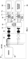
FIG. 1 is a schematic diagram of a grid-shielded electrical system with dedicated voltage sensors in accordance with exemplary embodiments; -
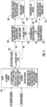
FIG. 2 is a flow diagram illustrating an operation of a controller of the grid-shielded electrical system ofFIG. 1 in accordance with exemplary embodiments; -
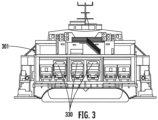
FIG. 3 is a front view of a transport ship in accordance with exemplary embodiments; -
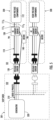
FIG. 4 is a schematic diagram of a grid-shielded electrical system with a distributed voltage sensor in accordance with exemplary embodiments; -
FIG. 5 is a schematic diagram of a grid-shielded electrical system with dedicated voltage sensors in accordance with alternative exemplary embodiments; -
FIG. 6 is a schematic diagram of a grid-shielded electrical system with a distributed voltage sensor in accordance with alternative exemplary embodiments; and -
FIG. 7 is a flow diagram illustrating a method of operating a grid-shielded electrical system in accordance with exemplary embodiments. - For the transportation of goods to some islands or countries, transportation by ship is often required (e.g., for transportation of goods between France and the UK or between Spain and the Canaries Islands). For these kinds of applications, containers with TRUs are used and are directly placed inside the ship in a closed area. Shipping durations can vary from as little as 2 hours or less or up to 8 hours or more.
- During the transportation on the sea, the diesel mode of operation of the TRUs can be completely forbidden and so the TRUs are required to operate in their standby modes in which power for the TRUs is received as grid power from an on-board ship generator. This power is delivered as internal three-phase grid power. It has been seen, however, that the three phases of the three-phase grid power provided by the on-board ship generator can be unbalanced or, in worst case scenarios, one of the phases can be lost, which can lead to a shutdown of the TRU and potential cargo losses.
- Currently, there is no way to detect an unbalanced phase or phase loss from the grid, which would help avoid the problems laid out above.
- As will be described below, a three-phases voltage measurement of the grid power is sensed by a voltage sensor upstream from an alternating current (AC) sensor to detect unbalanced phase and phase loss in power supplied from the grid. The voltage sensor can be placed inside the TRU on high voltage circuits and will provide readings to the corresponding microcontroller. The readings and internal logic will allow the TRU to detect if the grid is delivering power characterized by an unbalanced phase or phase loss.
- With reference to
FIG. 1 , a grid-shieldedelectrical system 101 is provided and includes a bus (hereinafter referred to as a "three-phase bus") 110, avoltage sensor 120, a current sensor 130 (which may be optional) and acontroller 140. - The three-
phase bus 110 can include first, second, and third phases 1111, 1112 and 1113 and is disposed to deliver three-phase grid power, which is received from agrid system 102, toelectrical components 112. Theelectrical components 112 can be high-voltage electrical components for conditioning an interior of a container (which may be referred to as a refrigerated container). Thegrid system 102 can be a grid of a transport ship as will be described further below. - The
voltage sensor 120 is disposed to sense a condition of voltage on each of the first, second, and third phases 1111, 1112 and 1113 of the three-phase bus 110 and is configured to generate voltage readings accordingly. Where applicable, thecurrent sensor 130 is disposed to sense a condition of current on each of the first, second, and third phases 1111, 1112 and 1113 of the three-phase bus 110 and is configured to generate current readings accordingly. Thecurrent sensor 130 may be, but is not required to be, electrically interposed between thevoltage sensor 120 and theelectrical components 112. - The following description will relate to the case in which the
current sensor 130 is provided in the grid-shieldedelectrical system 101. This is being done for clarity and brevity and it is to be understood that the present application and the claims are not limited to this embodiment. - The
controller 140 is disposed in signal communication with thevoltage sensor 120 and with thecurrent sensor 130. Thecontroller 140 includes a processor, a memory unit, and a networking unit by which the processor is communicative with at least thevoltage sensor 120, thecurrent sensor 130, external devices, and user interfaces. The memory unit has executable instructions stored thereon, which are readable and executable by the processor. When the executable instructions are read and executed by the processor, the executable instructions cause the processor and by extension thecontroller 140 to operate as described herein. - With the
controller 140 constructed as described above, thecontroller 140 is configured to detect a root cause issue with thegrid system 102 based on the voltage readings generated by thevoltage sensor 120, or, in an absence of the root cause issue, to detect a non-grid issue based on the current readings generated by thecurrent sensor 130. In greater detail, thecontroller 140 is configured to detect the root cause issue from at least one of an unbalanced phase and a phase loss for a predefined time for each of the first, second, and third phases 1111, 1112, and 1113 of the three-phase bus 110 based on the voltage readings generated by thevoltage sensor 120. Thecontroller 140 is also configured to detect, in the absence of the root cause issue, the non-grid issue from at least one of a low amperage condition and a sustained high amperage condition for each of the first, second, and third phases 1111, 1112, and 1113 of the three-phase bus 110 based on the current readings generated by thecurrent sensor 140. - The
controller 140 is further configured to shut down theelectrical components 112 when the root cause issue is detected and to automatically restart theelectrical components 112 once the root cause issue is no longer detected (i.e., cured). Thecontroller 140 is also further configured to continue operations of theelectrical components 112 in the absence of the root cause issue and in an absence of the non-root cause issue. - With reference to
FIG. 2 , the operations of thecontroller 140 that are described above are shown along with additional details. - The
controller 140, atblock 201, is initially receptive of data that is indicative of the readings of thevoltage sensor 120 and thecurrent sensor 130. At this point, thecontroller 140 analyzes the data of the readings of thevoltage sensor 120 for evidence of the at least one of an unbalanced phase and a phase loss for a predefined time for each of the first, second, and third phases 1111, 1112, and 1113 of the three-phase bus 110. Thecontroller 140 can also analyze the data of the readings of thecurrent sensor 130 for evidence of the at least one of a low amperage condition and a sustained high amperage condition for each of the first, second, and third phases 1111, 1112, and 1113 of the three-phase bus 110 (this analysis of thecurrent sensor 130 data can be delayed). - In an event that the
controller 140 detects from thevoltage sensor 120 data that the root cause issue with thegrid system 102 is currently in effect atblock 202, thecontroller 140 can shut down at least theelectrical components 112 until the root cause issue is corrected atblock 203 and can automatically restart the electrical components when the root cause issue is no longer detected atblock 204. In an event that thecontroller 140 does not detect that the root cause issue with thegrid system 102 is currently in effect atblock 202, thecontroller 140 can then determine whether there is a non-grid (i.e., unit) issue from thecurrent sensor 130 data atblock 205. If not, thecontroller 140 will continue operations of theelectrical components 112 atblock 206. If so, the controller will determine a type of the non-grid issue at blocks 207 and 208 and take the appropriate steps accordingly atblocks - With reference back to
FIG. 1 and with additional reference toFIGS. 3-6 , atransport ship 301 is provided. Thetransport ship 301 includes a three-phase grid 310 (i.e., the grid system 102) and agenerator 320 to which the three-phase grid 310 is connected. Thegenerator 320 can be configured to generate power (i.e., three-phase electrical power). - As shown in
FIGS. 1 and4 , thetransport ship 301 further includes at least oneTRU 330 in which the three-phase bus 110, theelectrical components 112, thevoltage sensor 120, thecurrent sensor 130 and thecontroller 140 are provided. The at least oneTRU 330 is operable in a standby mode while on board thetransport ship 301 as per relevant jurisdictional requirements and is connected to the three-phase grid 310 to receive the three-phase grid power at the three-phase bus 110 for exclusively powering theelectrical components 112 in the stand-by mode. In cases in which thetransport ship 301 includesmultiple TRUs 330, thevoltage sensor 120 can be provided asmultiple voltage sensors 120 that are each provided as a dedicated voltage sensor for a corresponding one of the TRUs 330 (seeFIG. 1 ). Alternatively, in cases in which thetransport ship 301 includesmultiple TRUs 330, thevoltage sensor 120 can be provided as a single distributed voltage sensor for each of the TRUs 330 (seeFIG. 4 ). - As shown in
FIGS. 5 and6 , thetransport ship 301 further includes at least oneTRU 330 in which the three-phase bus 110, theelectrical components 112, thecurrent sensor 130 and thecontroller 140 are provided with thevoltage sensor 120 provided externally. The at least oneTRU 330 is operable in a standby mode while on board thetransport ship 301 and is connected to the three-phase grid 310 to receive the three-phase grid power at the three-phase bus 110 for exclusively powering theelectrical components 112 in the stand-by mode. Thevoltage sensor 120 is electrically interposed between the three-phase grid 310 and the at least oneTRU 330. In cases in which thetransport ship 301 includesmultiple TRUs 330, thevoltage sensor 120 can be provided asmultiple voltage sensors 120 that are each provided as a dedicated voltage sensor for a corresponding one of the TRUs 330 (seeFIG. 5 ). Alternatively, in cases in which thetransport ship 301 includesmultiple TRUs 330, thevoltage sensor 120 can be provided as a single distributed voltage sensor for each of the TRUs 330 (seeFIG. 6 ). - With reference to
FIG. 7 , a method of operating a grid-shielded electrical system as described above is provided. As shown inFIG. 7 , the method includes delivering three-phase grid power, which is received from a grid, to electrical components via a three-phase bus (block 701), sensing a condition of voltage on each phase of the three-phase bus and generating voltage readings accordingly (block 702), sensing a condition of current on each phase of the three-phase bus and generating current readings accordingly (block 703) and detecting a root cause issue with the grid based on the voltage readings (block 704), or, in an absence of the root cause issue, detecting a non-grid issue based on the current readings (block 705). - The detecting of the root cause issue of
block 704 can include detecting the root cause issue from at least one of an unbalanced phase and a phase loss for a predefined time for each phase of the three-phase bus based on the voltage readings. The detecting of the non-grid issue ofblock 705 can include detecting, in the absence of the root cause issue, the non-grid issue from at least one of a low amperage condition and a sustained high amperage condition for each phase of the three-phase bus based on the current readings. - The method can further include shutting down the electrical components when the root cause issue is detected (block 706) and automatically restarting the electrical components once the root cause issue is no longer detected (block 707) or continuing operations of the electrical components in the absence of the root cause issue and in an absence of the non-root cause issue (block 708).
- Technical effects and benefits of the present disclosure are the provision of a grid shield to detect unbalanced phase and loss phase from a grid point-of-view. While a root cause of an A128 error cannot be currently known, the grid shield will make it possible to detect the case of a grid issue itself and so avoid the problems of alarm and shutdowns. This will prevent losses of cargo and increase TRU operational time. This will also detect power source issues, prevent labor problems and increase customer satisfaction.
- While the disclosure is provided in detail in connection with only a limited number of embodiments, it should be readily understood that the disclosure is not limited to such disclosed embodiments. Rather, the disclosure can be modified to incorporate any number of variations, alterations, substitutions or equivalent arrangements not heretofore described, but which are commensurate with the spirit and scope of the disclosure. Additionally, while various embodiments of the disclosure have been described, it is to be understood that the exemplary embodiment(s) may include only some of the described exemplary aspects. Accordingly, the disclosure is not to be seen as limited by the foregoing description, but is only limited by the scope of the appended claims.
Claims (15)
- A grid-shielded electrical system (101) for a transportation refrigeration system, the grid-shielded electrical system comprising:a bus (110) to deliver three-phase grid power, which is received from a grid (310), to electrical components (112) of the transportation refrigeration system;a voltage sensor (120) disposed to sense a condition of voltage on the bus (110) and configured to generate voltage readings accordingly; anda controller (140) disposed in signal communication with the voltage sensor (120) and configured to detect a root cause issue with the grid (310) based on the voltage readings.
- The grid-shielded electrical system (101) according to claim 1, wherein:the bus (110) comprises a three-phase bus, the voltage sensor (120) disposed to sense a condition of voltage on each phase of the three-phase bus;and/orthe bus (110) comprises a three-phase bus,the voltage sensor (120) senses the condition of voltage on each phase of the three-phase bus, andthe controller (140) is configured to detect the root cause issue from at least one of an unbalanced phase and a phase loss for a predefined time for each phase of the three-phase bus based on the voltage readings.
- The grid-shielded electrical system (101) according to claim 1 or 2, wherein the controller (140) is further configured to shut down the electrical components (112) when the root cause issue is detected and to automatically restart the electrical components once the root cause issue is no longer detected.
- The grid-shielded electrical system (101) according to claim 1, 2 or 3, wherein:the grid-shielded electrical system further comprises a current sensor (130) disposed to sense a condition of current on the bus (110) and configured to generate current readings accordingly, andthe controller (140) is disposed in signal communication with the current sensor (130) and configured to detect, in an absence of the root cause issue, a non-grid issue based on the current readings.
- The grid-shielded electrical system (101) according to claim 4, wherein:the bus (110) comprises a three-phase bus,the current sensor (130) senses the condition of current on each phase of the three-phase bus, andthe controller (140) is configured to detect, in the absence of the root cause issue, the non-grid issue from at least one of a low amperage condition and a sustained high amperage condition for each phase of the three-phase bus based on the current readings.
- The grid-shielded electrical system (101) according to claim 4 or 5, wherein the controller (140) is further configured to continue operations of the electrical components (112) in the absence of the root cause issue and in an absence of the non-root cause issue.
- A transportation refrigeration unit (330) for a shipping container, the shipping container configured to be transported by a ship (301), the transportation refrigeration unit comprising:a grid-shielded electrical system (101), the grid-shielded electrical system comprising:a bus (110) to deliver three-phase grid power, which is received from a grid (310) of the ship, to electrical components (112) of the transportation refrigeration system;a voltage sensor (120) disposed to sense a condition of voltage delivered to the bus and configured to generate voltage readings accordingly; anda controller (140) disposed in signal communication with the voltage sensor and configured to detect a root cause issue with the grid (310) based on the voltage readings,wherein the transportation refrigeration unit is operable in a standby mode while on board the transport ship and connected to the grid, the grid exclusively powering the electrical components in the stand-by mode.
- The transportation refrigeration unit according to claim 7, wherein the voltage sensor (120) is configured across multiple grid-shielded electrical systems (101) of multiple transportation refrigeration units, each respectively comprising an independent bus (110) and an independent controller (140), the voltage sensor disposed to sense a condition of voltage on each bus and configured to generate voltage readings accordingly.
- The transportation refrigeration unit according to claim 7, wherein the voltage sensor (120) is disposed on the bus (110) of the transportation refrigeration unit.
- The transportation refrigeration unit according to claim 7, wherein the voltage sensor (120) is disposed between the bus (110) of the transportation refrigeration unit and the grid (310).
- The transportation refrigeration unit according to any of claims 7 to 10, wherein the grid-shielded electrical system (101) further comprises a current sensor (130) disposed to sense a condition of current on the bus (110) and configured to generate current readings accordingly, the controller (140) is disposed in signal communication with the current sensor (130) and configured to detect, in an absence of the root cause issue, a non-grid issue based on the current readings;
and/or, wherein the grid-shielded electrical system (101) comprises the grid-shielded electrical system of any of claims 1 to 6. - A method of operating a transportation refrigeration system comprising a grid-shielded electrical system (101), the method comprising:delivering three-phase grid power, which is received from a grid (310), to electrical components (112) of the transportation refrigeration system via a three-phase bus (110);sensing, with a voltage sensor (120), a condition of voltage on each phase of the three-phase bus (110) and generating voltage readings accordingly; anddetecting, with a controller (140), a root cause issue with the grid (310) based on the voltage readings.
- The method according to claim 12, wherein the detecting of the root cause issue comprises detecting the root cause issue from at least one of an unbalanced phase and a phase loss for a predefined time for each phase of the three-phase bus (110) based on the voltage readings.
- The method according to claim 12 or 13, wherein the method further comprises:sensing, with a current sensor (130), a condition of current on each phase of the three-phase bus (110) and generating current readings accordingly; anddetecting, with a controller (140), in an absence of the root cause issue, detecting a non-grid issue based on the current readings;optionally, wherein the detecting of the non-grid issue comprises detecting, in the absence of the root cause issue, the non-grid issue from at least one of a low amperage condition and a sustained high amperage condition for each phase of the three-phase bus (110) based on the current readings.
- The method according to claim 14, further comprising:shutting down the electrical components (112) when the root cause issue is detected;automatically restarting the electrical components (112) once the root cause issue is no longer detected; andcontinuing operations of the electrical components (112) in the absence of the root cause issue and in an absence of the non-root cause issue.
Applications Claiming Priority (1)
| Application Number | Priority Date | Filing Date | Title |
|---|---|---|---|
| US202263333771P | 2022-04-22 | 2022-04-22 |
Publications (1)
| Publication Number | Publication Date |
|---|---|
| EP4266520A1 true EP4266520A1 (en) | 2023-10-25 |
Family
ID=86142623
Family Applications (1)
| Application Number | Title | Priority Date | Filing Date |
|---|---|---|---|
| EP23169227.8A Pending EP4266520A1 (en) | 2022-04-22 | 2023-04-21 | Grid shield |
Country Status (3)
| Country | Link |
|---|---|
| US (1) | US20230344224A1 (en) |
| EP (1) | EP4266520A1 (en) |
| CN (1) | CN116937537A (en) |
Citations (4)
| Publication number | Priority date | Publication date | Assignee | Title |
|---|---|---|---|---|
| KR101522955B1 (en) * | 2015-01-19 | 2015-05-28 | 에이치제이산전(주) | Circuit braker capable of protecting open phase |
| US20150349548A1 (en) * | 2012-12-31 | 2015-12-03 | Thermo King Corporation | Offset current implementation for battery charger |
| US20170282714A1 (en) * | 2016-03-31 | 2017-10-05 | Thermo King Corporation | Method and system for detecting and managing an electrical phase loss condition in a climate controlled transport system |
| US11303107B2 (en) * | 2017-02-28 | 2022-04-12 | Carrier Corporation | Apparatus and method for detecting current overload and leakage in a transport refrigeration unit |
-
2023
- 2023-04-19 US US18/302,931 patent/US20230344224A1/en active Pending
- 2023-04-21 EP EP23169227.8A patent/EP4266520A1/en active Pending
- 2023-04-21 CN CN202310433851.4A patent/CN116937537A/en active Pending
Patent Citations (4)
| Publication number | Priority date | Publication date | Assignee | Title |
|---|---|---|---|---|
| US20150349548A1 (en) * | 2012-12-31 | 2015-12-03 | Thermo King Corporation | Offset current implementation for battery charger |
| KR101522955B1 (en) * | 2015-01-19 | 2015-05-28 | 에이치제이산전(주) | Circuit braker capable of protecting open phase |
| US20170282714A1 (en) * | 2016-03-31 | 2017-10-05 | Thermo King Corporation | Method and system for detecting and managing an electrical phase loss condition in a climate controlled transport system |
| US11303107B2 (en) * | 2017-02-28 | 2022-04-12 | Carrier Corporation | Apparatus and method for detecting current overload and leakage in a transport refrigeration unit |
Also Published As
| Publication number | Publication date |
|---|---|
| CN116937537A (en) | 2023-10-24 |
| US20230344224A1 (en) | 2023-10-26 |
Similar Documents
| Publication | Publication Date | Title |
|---|---|---|
| US9404947B2 (en) | Systems and methods for detecting power quality of uninterrupible power supplies | |
| JP4820461B2 (en) | Distributed power system | |
| EP3342676B1 (en) | Electric power steering device | |
| US10742023B2 (en) | Air conditioner | |
| JP6984390B2 (en) | Power control unit | |
| US10957506B2 (en) | Controller, distributed power supply, and method for checking for welding | |
| JP6118043B2 (en) | Display device | |
| EP3252908B1 (en) | Power management device configured to determine mounting directions of current sensors of a power grid | |
| US20140333138A1 (en) | System and method for maintaining proper phase neutral wiring in a power system | |
| US7402965B2 (en) | DC common bus self-protection method and system | |
| US20230344224A1 (en) | Grid shield | |
| CN105075050B (en) | Ground fault protection systems and methods | |
| JP5286935B2 (en) | Distributed power supply | |
| JP2003319561A (en) | Power generation system | |
| JP2020092532A (en) | Power storage system and current sensor abnormality determination method | |
| US10468964B1 (en) | Detection and compensation of power phase loss | |
| EP3776804B1 (en) | Detection and compensation of power phase loss | |
| CN117072396A (en) | Distributed control water supply equipment and control method | |
| KR100425171B1 (en) | Digital motor controller equiped ammeter of three phase | |
| US11101660B2 (en) | Storage battery system and power display device | |
| JP6368606B2 (en) | Distributed power system and power conditioner | |
| KR20250139434A (en) | voltage sag protector with multiple temperature sensors installed | |
| CN119395377A (en) | Insulation impedance detection method, system and storage medium of inverter system based on rectifier circuit auxiliary power supply | |
| CN121332509A (en) | Low Voltage Ride-Through Control Method and Device for Coal Feeders | |
| US20190319482A1 (en) | Power supply device |
Legal Events
| Date | Code | Title | Description |
|---|---|---|---|
| PUAI | Public reference made under article 153(3) epc to a published international application that has entered the european phase |
Free format text: ORIGINAL CODE: 0009012 |
|
| STAA | Information on the status of an ep patent application or granted ep patent |
Free format text: STATUS: THE APPLICATION HAS BEEN PUBLISHED |
|
| AK | Designated contracting states |
Kind code of ref document: A1 Designated state(s): AL AT BE BG CH CY CZ DE DK EE ES FI FR GB GR HR HU IE IS IT LI LT LU LV MC ME MK MT NL NO PL PT RO RS SE SI SK SM TR |
|
| STAA | Information on the status of an ep patent application or granted ep patent |
Free format text: STATUS: REQUEST FOR EXAMINATION WAS MADE |
|
| 17P | Request for examination filed |
Effective date: 20240424 |
|
| RBV | Designated contracting states (corrected) |
Designated state(s): AL AT BE BG CH CY CZ DE DK EE ES FI FR GB GR HR HU IE IS IT LI LT LU LV MC ME MK MT NL NO PL PT RO RS SE SI SK SM TR |