EP4266471A1 - Energy storage system - Google Patents
Energy storage system Download PDFInfo
- Publication number
- EP4266471A1 EP4266471A1 EP22758111.3A EP22758111A EP4266471A1 EP 4266471 A1 EP4266471 A1 EP 4266471A1 EP 22758111 A EP22758111 A EP 22758111A EP 4266471 A1 EP4266471 A1 EP 4266471A1
- Authority
- EP
- European Patent Office
- Prior art keywords
- shell
- explosion
- proof valve
- thermal insulation
- energy storage
- Prior art date
- Legal status (The legal status is an assumption and is not a legal conclusion. Google has not performed a legal analysis and makes no representation as to the accuracy of the status listed.)
- Pending
Links
Images


Classifications
-
- H—ELECTRICITY
- H01—ELECTRIC ELEMENTS
- H01M—PROCESSES OR MEANS, e.g. BATTERIES, FOR THE DIRECT CONVERSION OF CHEMICAL ENERGY INTO ELECTRICAL ENERGY
- H01M50/00—Constructional details or processes of manufacture of the non-active parts of electrochemical cells other than fuel cells, e.g. hybrid cells
- H01M50/30—Arrangements for facilitating escape of gases
- H01M50/317—Re-sealable arrangements
- H01M50/325—Re-sealable arrangements comprising deformable valve members, e.g. elastic or flexible valve members
-
- H—ELECTRICITY
- H01—ELECTRIC ELEMENTS
- H01M—PROCESSES OR MEANS, e.g. BATTERIES, FOR THE DIRECT CONVERSION OF CHEMICAL ENERGY INTO ELECTRICAL ENERGY
- H01M10/00—Secondary cells; Manufacture thereof
- H01M10/60—Heating or cooling; Temperature control
- H01M10/65—Means for temperature control structurally associated with the cells
- H01M10/658—Means for temperature control structurally associated with the cells by thermal insulation or shielding
-
- H—ELECTRICITY
- H01—ELECTRIC ELEMENTS
- H01M—PROCESSES OR MEANS, e.g. BATTERIES, FOR THE DIRECT CONVERSION OF CHEMICAL ENERGY INTO ELECTRICAL ENERGY
- H01M50/00—Constructional details or processes of manufacture of the non-active parts of electrochemical cells other than fuel cells, e.g. hybrid cells
- H01M50/20—Mountings; Secondary casings or frames; Racks, modules or packs; Suspension devices; Shock absorbers; Transport or carrying devices; Holders
- H01M50/204—Racks, modules or packs for multiple batteries or multiple cells
- H01M50/207—Racks, modules or packs for multiple batteries or multiple cells characterised by their shape
- H01M50/209—Racks, modules or packs for multiple batteries or multiple cells characterised by their shape adapted for prismatic or rectangular cells
-
- H—ELECTRICITY
- H01—ELECTRIC ELEMENTS
- H01M—PROCESSES OR MEANS, e.g. BATTERIES, FOR THE DIRECT CONVERSION OF CHEMICAL ENERGY INTO ELECTRICAL ENERGY
- H01M50/00—Constructional details or processes of manufacture of the non-active parts of electrochemical cells other than fuel cells, e.g. hybrid cells
- H01M50/20—Mountings; Secondary casings or frames; Racks, modules or packs; Suspension devices; Shock absorbers; Transport or carrying devices; Holders
- H01M50/233—Mountings; Secondary casings or frames; Racks, modules or packs; Suspension devices; Shock absorbers; Transport or carrying devices; Holders characterised by physical properties of casings or racks, e.g. dimensions
- H01M50/24—Mountings; Secondary casings or frames; Racks, modules or packs; Suspension devices; Shock absorbers; Transport or carrying devices; Holders characterised by physical properties of casings or racks, e.g. dimensions adapted for protecting batteries from their environment, e.g. from corrosion
-
- H—ELECTRICITY
- H01—ELECTRIC ELEMENTS
- H01M—PROCESSES OR MEANS, e.g. BATTERIES, FOR THE DIRECT CONVERSION OF CHEMICAL ENERGY INTO ELECTRICAL ENERGY
- H01M50/00—Constructional details or processes of manufacture of the non-active parts of electrochemical cells other than fuel cells, e.g. hybrid cells
- H01M50/20—Mountings; Secondary casings or frames; Racks, modules or packs; Suspension devices; Shock absorbers; Transport or carrying devices; Holders
- H01M50/271—Lids or covers for the racks or secondary casings
-
- H—ELECTRICITY
- H01—ELECTRIC ELEMENTS
- H01M—PROCESSES OR MEANS, e.g. BATTERIES, FOR THE DIRECT CONVERSION OF CHEMICAL ENERGY INTO ELECTRICAL ENERGY
- H01M50/00—Constructional details or processes of manufacture of the non-active parts of electrochemical cells other than fuel cells, e.g. hybrid cells
- H01M50/30—Arrangements for facilitating escape of gases
-
- H—ELECTRICITY
- H01—ELECTRIC ELEMENTS
- H01M—PROCESSES OR MEANS, e.g. BATTERIES, FOR THE DIRECT CONVERSION OF CHEMICAL ENERGY INTO ELECTRICAL ENERGY
- H01M50/00—Constructional details or processes of manufacture of the non-active parts of electrochemical cells other than fuel cells, e.g. hybrid cells
- H01M50/30—Arrangements for facilitating escape of gases
- H01M50/317—Re-sealable arrangements
- H01M50/325—Re-sealable arrangements comprising deformable valve members, e.g. elastic or flexible valve members
- H01M50/333—Spring-loaded vent valves
-
- H—ELECTRICITY
- H01—ELECTRIC ELEMENTS
- H01M—PROCESSES OR MEANS, e.g. BATTERIES, FOR THE DIRECT CONVERSION OF CHEMICAL ENERGY INTO ELECTRICAL ENERGY
- H01M50/00—Constructional details or processes of manufacture of the non-active parts of electrochemical cells other than fuel cells, e.g. hybrid cells
- H01M50/30—Arrangements for facilitating escape of gases
- H01M50/342—Non-re-sealable arrangements
- H01M50/3425—Non-re-sealable arrangements in the form of rupturable membranes or weakened parts, e.g. pierced with the aid of a sharp member
-
- H—ELECTRICITY
- H01—ELECTRIC ELEMENTS
- H01M—PROCESSES OR MEANS, e.g. BATTERIES, FOR THE DIRECT CONVERSION OF CHEMICAL ENERGY INTO ELECTRICAL ENERGY
- H01M50/00—Constructional details or processes of manufacture of the non-active parts of electrochemical cells other than fuel cells, e.g. hybrid cells
- H01M50/30—Arrangements for facilitating escape of gases
- H01M50/383—Flame arresting or ignition-preventing means
-
- H—ELECTRICITY
- H01—ELECTRIC ELEMENTS
- H01M—PROCESSES OR MEANS, e.g. BATTERIES, FOR THE DIRECT CONVERSION OF CHEMICAL ENERGY INTO ELECTRICAL ENERGY
- H01M2220/00—Batteries for particular applications
- H01M2220/10—Batteries in stationary systems, e.g. emergency power source in plant
-
- H—ELECTRICITY
- H01—ELECTRIC ELEMENTS
- H01M—PROCESSES OR MEANS, e.g. BATTERIES, FOR THE DIRECT CONVERSION OF CHEMICAL ENERGY INTO ELECTRICAL ENERGY
- H01M2220/00—Batteries for particular applications
- H01M2220/20—Batteries in motive systems, e.g. vehicle, ship, plane
-
- H—ELECTRICITY
- H01—ELECTRIC ELEMENTS
- H01M—PROCESSES OR MEANS, e.g. BATTERIES, FOR THE DIRECT CONVERSION OF CHEMICAL ENERGY INTO ELECTRICAL ENERGY
- H01M50/00—Constructional details or processes of manufacture of the non-active parts of electrochemical cells other than fuel cells, e.g. hybrid cells
- H01M50/20—Mountings; Secondary casings or frames; Racks, modules or packs; Suspension devices; Shock absorbers; Transport or carrying devices; Holders
- H01M50/204—Racks, modules or packs for multiple batteries or multiple cells
-
- Y—GENERAL TAGGING OF NEW TECHNOLOGICAL DEVELOPMENTS; GENERAL TAGGING OF CROSS-SECTIONAL TECHNOLOGIES SPANNING OVER SEVERAL SECTIONS OF THE IPC; TECHNICAL SUBJECTS COVERED BY FORMER USPC CROSS-REFERENCE ART COLLECTIONS [XRACs] AND DIGESTS
- Y02—TECHNOLOGIES OR APPLICATIONS FOR MITIGATION OR ADAPTATION AGAINST CLIMATE CHANGE
- Y02E—REDUCTION OF GREENHOUSE GAS [GHG] EMISSIONS, RELATED TO ENERGY GENERATION, TRANSMISSION OR DISTRIBUTION
- Y02E60/00—Enabling technologies; Technologies with a potential or indirect contribution to GHG emissions mitigation
- Y02E60/10—Energy storage using batteries
Definitions
- the present application relates to the technical field of energy storage, and in particular relates to an energy storage system.
- the present application provides an energy storage system, which can effectively improve the safety of the energy storage system.
- the present application provides an energy storage system including a first shell
- the sealing member By arranging the sealing member, the fluid sealing between the first shell and the second shell can be achieved, so that the space between the first shell and the second shell is fluidly isolated from the inner space of the sealing member.
- the fluid entering the inner space of the sealing member through the first explosion-proof valve will not leak into the space between the first shell and the second shell, thereby preventing pressure in the space between the first shell and second shell from increasing or even causing an explosion, so that it can effectively improve the security of the energy storage system.
- the second explosion-proof valve is configured to be opened when a pressure of the inner space of the sealing member is greater than an opening pressure of the second explosion-proof valve.
- a connecting member may not be arranged between the first explosion-proof valve and the second explosion-proof valve. The opening of the second explosion-proof valve depends on the pressure of the inner space of the sealing member. After the first explosion-proof valve is opened, the gas inside the battery will enter the inner space of the sealing member through the first explosion-proof valve, so that the pressure of the inner space of the sealing member can increase; when the pressure of the inner space of the sealing member increases to reach the opening pressure of the second explosion-proof valve, the second explosion-proof valve will be opened.
- the energy storage system further includes a connecting member.
- the connecting member is connected between the first explosion-proof valve and the second explosion-proof valve, so that the second explosion-proof valve is linked with the first explosion-proof valve.
- a linkage between the second explosion-proof valve and the first explosion-proof valve can be realized, that is, when the first explosion-proof valve is opened, the first explosion-proof valve will drive the second explosion-proof valve to open at the same time through the connecting member, so as to realize the purpose of discharging the gas in the sealing member in time and prevent the gas from accumulating in the sealing member and causing explosion.
- the advantage of the embodiment is that even if the sealing member leaks fluid during use due to some reasons, the second explosion-proof valve can be opened in time as the state of the first explosion-proof valve changes, and the pressure can be released quickly.
- the first explosion-proof valve includes a first valve body and a first valve core; when the first explosion-proof valve is in an opening state, the first valve core moves relative to the first valve body to communicate with the inner space of the second shell and the inner space of the sealing member; the second explosion-proof valve includes a second valve body and a second valve core; when the second explosion-proof valve is in an opening state, the second valve core moves relative to the second valve body to communicate with the inner space of the sealing member and the outer space of the first shell; the connecting member is connected between the first valve core and the second valve core.
- the first valve core moves relative to the first valve body in a direction close to the second explosion-proof valve to open a pressure-relief opening, so that the gas can be discharged to the inner space of the sealing member through the pressure-relief opening.
- the second valve core is driven to move in a direction away from the first explosion-proof valve through the connecting member, thereby opening the pressure-relief opening of the second explosion-proof valve, so that the gas inside the sealing member can be discharged to the outside of the first shell, and the purpose of pressure relief can be achieved.
- the connecting member includes a rigid rod.
- the advantage of using the rigid rod is that when the first valve core moves, the second valve core can be directly driven to start synchronous movement through the connecting member, so as to prevent the occurrence of linkage delay.
- the energy storage system further includes a first sealing gasket arranged between the first explosion-proof valve and the second shell and a second sealing gasket arranged between the second explosion-proof valve and the first shell.
- the sealing effect between the first explosion-proof valve and the second shell and the sealing effect between the second explosion-proof valve and the first shell can be enhanced to prevent the leakage of the gas in the inner space of the sealing member.
- the energy storage system further includes a first thermal insulation member.
- the first thermal insulation member is mounted on an inner wall of the first shell, and the sealing member passes through the first thermal insulation member.
- the thermal insulation function of the energy storage system can be realized, and the energy storage system can be prevented from being affected by the temperature of the external environment.
- the energy storage system further includes a second thermal insulation member.
- a thickness of the first thermal insulation member is smaller than a distance between the first shell and the second shell, and the second thermal insulation member is arranged on an outer periphery of the sealing member and is located between the first thermal insulation member and the second shell.
- the sealing member passes through the first thermal insulation member, there is no first thermal insulation member at the sealing member for thermal insulation.
- the second thermal insulation member By arranging the second thermal insulation member, a portion between the sealing member and the second shell can be thermally insulated, so as to prevent the first shell from reducing the thermal insulation effect due to arranging the second explosion-proof valve.
- a hardness of the second thermal insulation member is smaller than a hardness of the first thermal insulation member. In this way, the second thermal insulation member can be properly compressed according to an actual distance between the first shell and the second shell, so as to fill the space between the first shell and the second shell, and ensure the thermal insulation effect.
- the first thermal insulation member includes a rock wool
- the second thermal insulation member includes a thermal insulation foam
- the "embodiment” referred in the present application means that a particular feature, a structure, or a characteristic described in connection with the embodiment can be included in at least one embodiment of the present application.
- the appearances of the phrase in various positions in the specification are not necessarily all referring to the same embodiment, nor a separate or alternative embodiment that is mutually exclusive of other embodiments. It is explicitly and implicitly understood by those skilled in the art that the embodiments described in the present application may be combined with other embodiments.
- the term “plurality” means two or more, unless expressly specifically defined otherwise.
- a plurality of groups means two or more groups, and “a plurality of sheets” refers to two or more sheets, unless otherwise specifically defined.
- the terms “mount”, “communicate”, “connect” and “fix” should be understood in a broad sense, for example, it can be a fixed connection, a detachable connection, or an integral connection, it can be a mechanical connection or an electrical connection; it can be a direct connection, or it can be connected indirectly through an intermediary, it can be a communication within the two elements or an interaction relationship between the two elements.
- the specific meaning of the above-mentioned terms in the present application can be understood according to specific situations.
- the inventors of the present application have noticed that a plurality of battery packs are arranged in an energy storage system, and a battery is arranged in the battery pack.
- gas inside the battery is directly discharged into the battery pack through an explosion-proof valve, and the combustible gas may cause the deflagration and explosion of the battery pack.
- the inventor has improved the structure of the energy storage system.
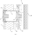
- the energy storage system includes a first shell 1, a battery pack 2, a sealing member 3, a first explosion-proof valve 4 and a second explosion-proof valve 5.
- the battery pack 2 is arranged inside the first shell 1.
- the battery pack 2 includes a second shell 21 and a battery 22 arranged in the second shell 21.
- the sealing member 3 is arranged between the first shell 1 and the second shell 21, and a space between the first shell 1 and the second shell 21 is fluidly isolated from an inner space of the sealing member 3.
- the first explosion-proof valve 4 is mounted on the second shell 21 to communicate with an inner space of the second shell 21 and the inner space of the sealing member 3 when the first explosion-proof valve 4 is opened.
- the second explosion-proof valve 5 is mounted on the first shell 1 to communicate with the inner space of the sealing member 3 and an outer space of the first shell 1 when the second explosion-proof valve 5 is opened.
- the sealing member 3 By arranging the sealing member 3, the fluid sealing between the first shell 1 and the second shell 21 can be achieved, so that the space between the first shell 1 and the second shell 21 is fluidly isolated from the inner space of the sealing member 3.
- the fluid entering the inner space of the sealing member 3 through the first explosion-proof valve 4 will not leak into the space between the first shell 1 and the second shell 21, thereby preventing pressure in the space between the first shell 1 and second shell 21 from increasing or even causing an explosion, so that it can effectively improve the security of the energy storage system.
- the sealing member 3 forms a directional smoke exhaust channel when thermal runaway occurs in the battery 22, so that the pressure inside the battery can be released in time.
- the fluid entering the inner space of the sealing member 3 through the first explosion-proof valve 4 can continue to press the second explosion-proof valve 5 and flow out of the first shell 1 after the second explosion-proof valve 5 is opened to realize the pressure relief of the battery 22.
- the structures of the first explosion-proof valve 4 and the second explosion-proof valve 5 may be the same or different.
- the sealing member 3 may be a sleeve structure, two ends of the sealing member 3 are respectively connected with the first shell 1 and the second shell 21, and the first explosion-proof valve 4 and the second explosion-proof valve 5 are respectively located at the two ends of the sealing member 3.
- the sealing member 3 may be connected with the first explosion-proof valve 4 and the second explosion-proof valve 5 by welding or bolt connection.
- first shell 1 and the second shell 21 are made of a hard material.
- the first shell 1 and the second shell 21 may be cylinder, cuboid or other shapes.
- the second explosion-proof valve 5 is configured to be opened when a pressure of the inner space of the sealing member 3 is greater than an opening pressure of the second explosion-proof valve 5.
- a connecting member may not be arranged between the first explosion-proof valve 4 and the second explosion-proof valve 5. The opening of the second explosion-proof valve 5 depends on the pressure of the inner space of the sealing member 3.
- the gas inside the battery 22 will enter the inner space of the sealing member 3 through the first explosion-proof valve 4, so that the pressure of the inner space of the sealing member 3 can increase; when the pressure of the inner space of the sealing member 3 increases to reach the opening pressure of the second explosion-proof valve 5, the second explosion-proof valve 5 will be opened.
- the energy storage system further includes a connecting member 6.
- the connecting member 6 is connected between the first explosion-proof valve 4 and the second explosion-proof valve 5, so that the second explosion-proof valve 5 is linked with the first explosion-proof valve 4.
- a linkage between the second explosion-proof valve 5 and the first explosion-proof valve 4 can be realized, that is, when the first explosion-proof valve 4 is opened, the first explosion-proof valve 4 will drive the second explosion-proof valve 5 to open at the same time through the connecting member 6, so as to realize the purpose of discharging the gas in the sealing member 3 in time and prevent the gas from accumulating in the sealing member 3 and causing explosion.
- the advantage of the embodiment is that even if the sealing member 3 leaks fluid during use due to some reasons, the second explosion-proof valve 5 can be opened in time as the state of the first explosion-proof valve 4 changes, and the pressure can be released quickly.
- the first explosion-proof valve 4 includes a first valve body 41 and a first valve core 42; when the first explosion-proof valve 4 is in an opening state, the first valve core 42 moves relative to the first valve body 41 to communicate with the inner space of the second shell 21 and the inner space of the sealing member 3; the second explosion-proof valve 5 includes a second valve body 51 and a second valve core 52; when the second explosion-proof valve 5 is in an opening state, the second valve core 52 moves relative to the second valve body 51 to communicate with the inner space of the sealing member 3 and the outer space of the first shell 1; the connecting member 6 is connected between the first valve core 42 and the second valve core 52.
- the first valve core 42 moves relative to the first valve body 41 in a direction close to the second explosion-proof valve 5 to open a pressure-relief opening, so that the gas can be discharged to the inner space of the sealing member 3 through the pressure-relief opening.
- the second valve core 52 is driven to move in a direction away from the first explosion-proof valve 4 through the connecting member 6, thereby opening the pressure-relief opening of the second explosion-proof valve 5, so that the gas inside the sealing member 3 can be discharged to the outside of the first shell 1, and the purpose of pressure relief can be achieved.
- the connecting member 6 includes a rigid rod.
- the advantage of using the rigid rod is that when the first valve core 42 moves, the second valve core 52 can be directly driven to start synchronous movement through the connecting member 6, so as to prevent the occurrence of linkage delay.
- the connecting member 6 may be a cylindrical rod member.
- a through hole is arranged in a center of the connecting member 6.
- the through hole can not only facilitate the connection with the first valve core 42 and the second valve core 52, but also reduce the total weight of the connecting member 6.
- the first explosion-proof valve 4 and the second explosion-proof valve 5 may adopt a one-way explosion-proof valve or a balanced explosion-proof valve.
- the energy storage system further includes a first sealing gasket 7 arranged between the first explosion-proof valve 4 and the second shell 21 and a second sealing gasket 8 arranged between the second explosion-proof valve 5 and the first shell 1.
- the sealing effect between the first explosion-proof valve 4 and the second shell 21 and the sealing effect between the second explosion-proof valve 5 and the first shell 1 can be enhanced to prevent the leakage of the gas in the inner space of the sealing member 3.
- first sealing gasket 7 and the second sealing gasket 8 may be the same or different.
- the first sealing gasket 7 includes an O-shaped rubber ring.
- a side face of the first valve body 41 close to the second shell 21 is provided with a groove, and the O-shaped rubber ring is arranged in the groove.
- the side face of the first valve body 41 close to the second shell 21 is in contact with an outer wall of the second shell 21.
- the second sealing gasket 8 includes a rubber ring, and the rubber ring includes a portion, in which an outer diameter of the portion gradually increases in the direction from the first shell 1 to the second shell 21.
- Amounting hole is arranged on the first shell 1.
- the rubber ring can be mounted at the mounting hole of the first shell 1 from an interior of the first shell 1 to the outside, so as to prevent the rubber ring from falling to the outside of the first shell 1.
- the rubber ring is sleeved on an outer periphery of the second explosion-proof valve 5 to prevent the gas in the space between the first shell 1 and the second shell 21 from leaking out through a mounting gap of the second explosion-proof valve 5.
- the energy storage system further includes a first thermal insulation member 9.
- the first thermal insulation member 9 is mounted on an inner wall of the first shell 1, and the sealing member 3 passes through the first thermal insulation member 9.
- the thermal insulation function of the energy storage system can be realized, and the energy storage system can be prevented from being affected by the temperature of the external environment.
- the first thermal insulation member 9 covers the entire inner wall of the first shell 1 to achieve the overall and comprehensive thermal insulation for the inner space of the first shell 1.
- the first thermal insulation member 9 includes a rock wool.
- the structure of rock wool is relatively easy to fix, and has better thermal insulation effect.
- the first thermal insulation member 9 can be mounted on the inner wall of the first shell 1 by the connecting member such as a bolt or the like.
- the energy storage system further includes a second thermal insulation member 10.
- a thickness of the first thermal insulation member 10 is smaller than a distance between the first shell 1 and the second shell 21, and the second thermal insulation member 10 is arranged on an outer periphery of the sealing member 3 and is located between the first thermal insulation member 9 and the second shell 21.
- the sealing member 3 passes through the first thermal insulation member 9, there is no first thermal insulation member 9 at the sealing member 3 for thermal insulation.
- the second thermal insulation member 10 a portion between the sealing member 3 and the second shell 21 can be thermally insulated, so as to prevent the first shell 1 from reducing the thermal insulation effect due to arranging the second explosion-proof valve 5.
- a hardness of the second thermal insulation member 10 is smaller than a hardness of the first thermal insulation member 9. In this way, the second thermal insulation member 10 can be properly compressed according to an actual distance between the first shell 1 and the second shell 21, so as to fill the space between the first shell 1 and the second shell 21, and ensure the thermal insulation effect.
- the second thermal insulation member 10 includes a thermal insulation foam.
- the hardness of thermal insulation foam is smaller than that of rock wool, and the thermal insulation foam has a certain compressibility, which is suitable for filling the space with an uncertain gap.
- the energy storage system provided by the present application may be an energy storage container or a mobile energy storage vehicle.
- the energy storage system includes the first shell 1, the battery pack 2, the sealing member 3, the first explosion-proof valve 4, the second explosion-proof valve 5, the first sealing gasket 7, the second sealing gasket 8, the first thermal insulation member 9 and the second thermal insulation member 10.
- the interior of the first shell 1 is provided with a plurality of battery packs 2, an electrical room and a water-cooling room for cooling the battery packs 2, and the like.
- the battery pack 2 includes the second shell 21 and the battery 22 arranged in the second shell 21.
- the first explosion-proof valve 4 is mounted on the second shell 21.
- the second explosion-proof valve 5 is mounted on the first shell 1.
- the sealing member 3 is arranged between the first shell 1 and the second shell 21, and is connected between the first explosion-proof valve 4 and the second explosion-proof valve 5
- the first sealing gasket 7 is arranged between the first explosion-proof valve 4 and the second shell 21, and the second sealing gasket 8 is arranged between the second explosion-proof valve 5 and the first shell 1.
- the first thermal insulation member 9 is mounted on the inner wall of the first shell 1, and the second thermal insulation member 10 is arranged on the outer periphery of the sealing member 3 and is located between the first thermal insulation member 9 and the second shell 21.
- the energy storage system in the embodiments can directly discharge the gas to the outside of the first shell 1 through the first explosion-proof valve 4 and the second explosion-proof valve 5 when the thermal runaway of the battery 22 occurs, and the energy storage system can have the thermal insulation function to adapt to application scenarios that require thermal insulation.
- the inner space of the sealing member 3 stores the air.
- the first explosion-proof valve 4 is opened, the gas inside the battery enters the sealing member 3, and the pressure inside the sealing member 3 continuously increases.
- the opening pressure of the second explosion-proof valve 5 is reached, the second explosion-proof valve 5 is opened, and the gas inside the battery is directly discharged to the outside of the first shell 1 to realize pressure relief.
- the connecting member 6 is added relative to the embodiment shown in Fig. 1 and Fig. 2 .
- the connecting member 6 is connected between the first valve core 42 of the first explosion-proof valve 4 and the second valve core 52 of the second explosion-proof valve 5.
- the first explosion-proof valve 4 is opened under pressure
- the displacement of the first explosion-proof valve 4 is transmitted to the second explosion-proof valve 5 through the connecting member 6, so that the second valve core 52 of the second explosion-proof valve 5 is opened under the force, so that the purposes of the linkage opening and pressure relief can be achieved.
- the energy storage system in the embodiments can also directly discharge the gas to the outside of the first shell 1 through the first explosion-proof valve 4 and the second explosion-proof valve 5 when the thermal runaway of the battery 22 occurs, and the energy storage system can have the thermal insulation function to adapt to application scenarios that require thermal insulation.
Landscapes
- Chemical & Material Sciences (AREA)
- Chemical Kinetics & Catalysis (AREA)
- Electrochemistry (AREA)
- General Chemical & Material Sciences (AREA)
- Engineering & Computer Science (AREA)
- Manufacturing & Machinery (AREA)
- Battery Mounting, Suspending (AREA)
- Gas Exhaust Devices For Batteries (AREA)
- Secondary Cells (AREA)
Abstract
Description
- The present application relates to the technical field of energy storage, and in particular relates to an energy storage system.
- The rapid development of the new energy industry has promoted the progress of the energy storage industry. With the continuous development of energy storage products, energy storage technology has developed from small-capacity research to large-capacity applications. Large-scale energy storage products such as energy storage containers and mobile energy storage vehicles have come out one after another.
- The safety of energy storage products is a key factor affecting the performance of energy storage products.
- The present application provides an energy storage system, which can effectively improve the safety of the energy storage system.
- In a first aspect, the present application provides an energy storage system including a first shell;
- a battery pack, arranged inside the first shell, in which the battery pack includes a second shell and a battery arranged in the second shell;
- a sealing member, arranged between the first shell and the second shell, in which a space between the first shell and the second shell is fluidly isolated from an inner space of the sealing member;
- a first explosion-proof valve, mounted on the second shell to communicate with an inner space of the second shell and the inner space of the sealing member when the first explosion-proof valve is opened; and
- a second explosion-proof valve, mounted on the first shell to communicate with the inner space of the sealing member and an outer space of the first shell when the second explosion-proof valve is opened.
- By arranging the sealing member, the fluid sealing between the first shell and the second shell can be achieved, so that the space between the first shell and the second shell is fluidly isolated from the inner space of the sealing member. When the thermal runaway of the battery occurs, the fluid entering the inner space of the sealing member through the first explosion-proof valve will not leak into the space between the first shell and the second shell, thereby preventing pressure in the space between the first shell and second shell from increasing or even causing an explosion, so that it can effectively improve the security of the energy storage system.
- In some embodiments, the second explosion-proof valve is configured to be opened when a pressure of the inner space of the sealing member is greater than an opening pressure of the second explosion-proof valve. In the embodiments, a connecting member may not be arranged between the first explosion-proof valve and the second explosion-proof valve. The opening of the second explosion-proof valve depends on the pressure of the inner space of the sealing member. After the first explosion-proof valve is opened, the gas inside the battery will enter the inner space of the sealing member through the first explosion-proof valve, so that the pressure of the inner space of the sealing member can increase; when the pressure of the inner space of the sealing member increases to reach the opening pressure of the second explosion-proof valve, the second explosion-proof valve will be opened.
- In some embodiments, the energy storage system further includes a connecting member. The connecting member is connected between the first explosion-proof valve and the second explosion-proof valve, so that the second explosion-proof valve is linked with the first explosion-proof valve.
- By arranging the connecting member, a linkage between the second explosion-proof valve and the first explosion-proof valve can be realized, that is, when the first explosion-proof valve is opened, the first explosion-proof valve will drive the second explosion-proof valve to open at the same time through the connecting member, so as to realize the purpose of discharging the gas in the sealing member in time and prevent the gas from accumulating in the sealing member and causing explosion. The advantage of the embodiment is that even if the sealing member leaks fluid during use due to some reasons, the second explosion-proof valve can be opened in time as the state of the first explosion-proof valve changes, and the pressure can be released quickly.
- In some embodiments, the first explosion-proof valve includes a first valve body and a first valve core; when the first explosion-proof valve is in an opening state, the first valve core moves relative to the first valve body to communicate with the inner space of the second shell and the inner space of the sealing member; the second explosion-proof valve includes a second valve body and a second valve core; when the second explosion-proof valve is in an opening state, the second valve core moves relative to the second valve body to communicate with the inner space of the sealing member and the outer space of the first shell; the connecting member is connected between the first valve core and the second valve core.
- When the first explosion-proof valve is opened, the first valve core moves relative to the first valve body in a direction close to the second explosion-proof valve to open a pressure-relief opening, so that the gas can be discharged to the inner space of the sealing member through the pressure-relief opening. When the first valve core moves relative to the first valve body, the second valve core is driven to move in a direction away from the first explosion-proof valve through the connecting member, thereby opening the pressure-relief opening of the second explosion-proof valve, so that the gas inside the sealing member can be discharged to the outside of the first shell, and the purpose of pressure relief can be achieved.
- In some embodiments, the connecting member includes a rigid rod. The advantage of using the rigid rod is that when the first valve core moves, the second valve core can be directly driven to start synchronous movement through the connecting member, so as to prevent the occurrence of linkage delay.
- In some embodiments, the energy storage system further includes a first sealing gasket arranged between the first explosion-proof valve and the second shell and a second sealing gasket arranged between the second explosion-proof valve and the first shell.
- By arranging the first sealing gasket and the second sealing gasket, the sealing effect between the first explosion-proof valve and the second shell and the sealing effect between the second explosion-proof valve and the first shell can be enhanced to prevent the leakage of the gas in the inner space of the sealing member.
- In some embodiments, the energy storage system further includes a first thermal insulation member. The first thermal insulation member is mounted on an inner wall of the first shell, and the sealing member passes through the first thermal insulation member.
- By arranging the first thermal insulation member, the thermal insulation function of the energy storage system can be realized, and the energy storage system can be prevented from being affected by the temperature of the external environment.
- In some embodiments, the energy storage system further includes a second thermal insulation member. A thickness of the first thermal insulation member is smaller than a distance between the first shell and the second shell, and the second thermal insulation member is arranged on an outer periphery of the sealing member and is located between the first thermal insulation member and the second shell.
- Since the sealing member passes through the first thermal insulation member, there is no first thermal insulation member at the sealing member for thermal insulation. By arranging the second thermal insulation member, a portion between the sealing member and the second shell can be thermally insulated, so as to prevent the first shell from reducing the thermal insulation effect due to arranging the second explosion-proof valve.
- In some embodiments, a hardness of the second thermal insulation member is smaller than a hardness of the first thermal insulation member. In this way, the second thermal insulation member can be properly compressed according to an actual distance between the first shell and the second shell, so as to fill the space between the first shell and the second shell, and ensure the thermal insulation effect.
- In some embodiments, the first thermal insulation member includes a rock wool, and/or the second thermal insulation member includes a thermal insulation foam.
- The above description is only an overview of the technical solution of the present application. In order to understand the technical means of the present application more clearly, it can be implemented according to the content of the description, and in order to make the above-mentioned and other objects, features and advantages of the present application more clearly understood, the following specific embodiments of the present application are given.
- In order to more clearly illustrate the technical solutions of the embodiments of the present application, the drawings to be used in the description of the embodiments of the present application will be described briefly below. Obviously, the drawings in the following description are merely some embodiments of the present application. For those skilled in the art, other drawings can also be obtained according to these drawings without the inventive labor.
-
Fig. 1 shows a schematic structural view of an energy storage system disclosed in some embodiments of the present application when a first explosion-proof valve and a second explosion-proof valve are in a closed state; -
Fig. 2 shows a schematic structural view of an energy storage system disclosed in some embodiments of the present application when a first explosion-proof valve and a second explosion-proof valve are in an opening state; -
Fig. 3 shows a schematic structural view of an energy storage system disclosed in some other embodiments of the present application when a first explosion-proof valve and a second explosion-proof valve are in a closed state; -
Fig. 4 shows a schematic structural view of an energy storage system disclosed in some other embodiments of the present application when a first explosion-proof valve and a second explosion-proof valve are in an opening state. - In the drawings, the drawings are not drawn to actual scale.
- Reference number:
1. first shell; 2. battery pack; 21. second shell; 22. battery; 3. sealing member; 4. first explosion-proof valve; 41. first valve body; 42. first valve core; 5. second explosion-proof valve; 51. second valve body; 52. second valve core; 6. connecting member; 7. first sealing gasket; 8. second sealing gasket; 9. first thermal insulation member; 10. second thermal insulation member. - The implementation of the present application will be described in further detail below in conjunction with the drawings and embodiments. The following embodiments are only used to illustrate the technical solutions of the present application more clearly, and are therefore only used as examples, and cannot be used to limit the protection scope of the present application.
- Unless otherwise defined, all technical and scientific terms used herein have the same meaning as commonly understood by those skilled in the technical filed to which the present application belongs. The terminology used herein is for the purpose of describing particular embodiments only and is not intended to limit the present application. The terms "comprising" and "having" and any variations thereof in the description and claims of the present application and the above description of the drawings are intended to cover non-exclusive inclusions.
- In the description of the embodiments of the present application, the technical terms "first", "second" and the like are only used to distinguish different objects, and should not be understood as indicating or implying relative importance or implying the quantity, specific order or priority relationship of the indicated technical features. Furthermore, the term "perpendicular" does not mean strictly perpendicular, but allows for an error within the allowable range. The term "parallel" does not mean strictly parallel, but allows for an error within the allowable range.
- The "embodiment" referred in the present application means that a particular feature, a structure, or a characteristic described in connection with the embodiment can be included in at least one embodiment of the present application. The appearances of the phrase in various positions in the specification are not necessarily all referring to the same embodiment, nor a separate or alternative embodiment that is mutually exclusive of other embodiments. It is explicitly and implicitly understood by those skilled in the art that the embodiments described in the present application may be combined with other embodiments.
- In the description of the present application, the term "and/or" is merely an association to describe the associated objects. It can mean that there are three kinds of relationships, such as A and/or B, which means that A exists alone, A and B exist at the same time, and B exists alone. In addition, the character "/" in the present application generally indicates that the related objects are an "or" relationship.
- In the description of the present application, the term "plurality" means two or more, unless expressly specifically defined otherwise. Similarly, "a plurality of groups" means two or more groups, and "a plurality of sheets" refers to two or more sheets, unless otherwise specifically defined.
- In the description of the present application, the technical terms "center", "longitudinal", "transverse", "length", "width", "thickness", "top", "bottom", "front", "rear", "left", "right", "vertical", "horizontal", "top", "bottom", "inside", "outside", "clockwise", "counterclockwise", "axial", "radial", "circumferential" and the like indicating the orientation or positional relationship are based on the orientation or positional relationship shown in the drawings, and are only for the convenience of describing the embodiments of the present application and simplifying the description, rather than indicating or implying that the referred device or element must have a specific direction or position or be constructed and operate in a specific direction or position. Therefore, it cannot be construed as a limitation on the embodiments of the present application.
- In the description of the present application, unless otherwise clearly specified and limited, the terms "mount", "communicate", "connect" and "fix" should be understood in a broad sense, for example, it can be a fixed connection, a detachable connection, or an integral connection, it can be a mechanical connection or an electrical connection; it can be a direct connection, or it can be connected indirectly through an intermediary, it can be a communication within the two elements or an interaction relationship between the two elements. For those of ordinary skill in the art, the specific meaning of the above-mentioned terms in the present application can be understood according to specific situations.
- With the promotion and application of new energy sources such as solar energy and wind energy, the energy storage technology has also developed. Due to the advantages of high energy, long service life, high rated voltage, high power tolerance, low self-discharge rate, light weight, green environmental protection and basically no water consumption in production, power batteries are gradually being used in energy storage power systems such as hydropower, thermal power, wind power and solar power plants.
- The inventors of the present application have noticed that a plurality of battery packs are arranged in an energy storage system, and a battery is arranged in the battery pack. When the thermal runaway of the battery occurs, gas inside the battery is directly discharged into the battery pack through an explosion-proof valve, and the combustible gas may cause the deflagration and explosion of the battery pack.
- In order to improve the safety of the energy storage system and prevent the energy storage system from exploding when the thermal runaway of the battery pack occurs, the inventor has improved the structure of the energy storage system.
- As shown in
Figs. 1 to 4 , in some embodiments of an energy storage system provided by the present application, the energy storage system includes afirst shell 1, abattery pack 2, a sealingmember 3, a first explosion-proof valve 4 and a second explosion-proof valve 5. Thebattery pack 2 is arranged inside thefirst shell 1. Thebattery pack 2 includes asecond shell 21 and abattery 22 arranged in thesecond shell 21. The sealingmember 3 is arranged between thefirst shell 1 and thesecond shell 21, and a space between thefirst shell 1 and thesecond shell 21 is fluidly isolated from an inner space of the sealingmember 3. The first explosion-proof valve 4 is mounted on thesecond shell 21 to communicate with an inner space of thesecond shell 21 and the inner space of the sealingmember 3 when the first explosion-proof valve 4 is opened. The second explosion-proof valve 5 is mounted on thefirst shell 1 to communicate with the inner space of the sealingmember 3 and an outer space of thefirst shell 1 when the second explosion-proof valve 5 is opened. - By arranging the sealing
member 3, the fluid sealing between thefirst shell 1 and thesecond shell 21 can be achieved, so that the space between thefirst shell 1 and thesecond shell 21 is fluidly isolated from the inner space of the sealingmember 3. When the thermal runaway of thebattery 22 occurs, the fluid entering the inner space of the sealingmember 3 through the first explosion-proof valve 4 will not leak into the space between thefirst shell 1 and thesecond shell 21, thereby preventing pressure in the space between thefirst shell 1 andsecond shell 21 from increasing or even causing an explosion, so that it can effectively improve the security of the energy storage system. - The sealing
member 3 forms a directional smoke exhaust channel when thermal runaway occurs in thebattery 22, so that the pressure inside the battery can be released in time. - The fluid entering the inner space of the sealing
member 3 through the first explosion-proof valve 4 can continue to press the second explosion-proof valve 5 and flow out of thefirst shell 1 after the second explosion-proof valve 5 is opened to realize the pressure relief of thebattery 22. - The structures of the first explosion-
proof valve 4 and the second explosion-proof valve 5 may be the same or different. - In some embodiments, the sealing
member 3 may be a sleeve structure, two ends of the sealingmember 3 are respectively connected with thefirst shell 1 and thesecond shell 21, and the first explosion-proof valve 4 and the second explosion-proof valve 5 are respectively located at the two ends of the sealingmember 3. The sealingmember 3 may be connected with the first explosion-proof valve 4 and the second explosion-proof valve 5 by welding or bolt connection. - In some embodiments, the
first shell 1 and thesecond shell 21 are made of a hard material. Thefirst shell 1 and thesecond shell 21 may be cylinder, cuboid or other shapes. - As shown in
Fig. 1 andFig. 2 , in some embodiments, the second explosion-proof valve 5 is configured to be opened when a pressure of the inner space of the sealingmember 3 is greater than an opening pressure of the second explosion-proof valve 5. In the embodiments, a connecting member may not be arranged between the first explosion-proof valve 4 and the second explosion-proof valve 5. The opening of the second explosion-proof valve 5 depends on the pressure of the inner space of the sealingmember 3. After the first explosion-proof valve 4 is opened, the gas inside thebattery 22 will enter the inner space of the sealingmember 3 through the first explosion-proof valve 4, so that the pressure of the inner space of the sealingmember 3 can increase; when the pressure of the inner space of the sealingmember 3 increases to reach the opening pressure of the second explosion-proof valve 5, the second explosion-proof valve 5 will be opened. - As shown in
Fig. 3 andFig. 4 , in some embodiments, the energy storage system further includes a connectingmember 6. The connectingmember 6 is connected between the first explosion-proof valve 4 and the second explosion-proof valve 5, so that the second explosion-proof valve 5 is linked with the first explosion-proof valve 4. By arranging the connectingmember 6, a linkage between the second explosion-proof valve 5 and the first explosion-proof valve 4 can be realized, that is, when the first explosion-proof valve 4 is opened, the first explosion-proof valve 4 will drive the second explosion-proof valve 5 to open at the same time through the connectingmember 6, so as to realize the purpose of discharging the gas in the sealingmember 3 in time and prevent the gas from accumulating in the sealingmember 3 and causing explosion. The advantage of the embodiment is that even if the sealingmember 3 leaks fluid during use due to some reasons, the second explosion-proof valve 5 can be opened in time as the state of the first explosion-proof valve 4 changes, and the pressure can be released quickly. - In some embodiments, the first explosion-
proof valve 4 includes afirst valve body 41 and afirst valve core 42; when the first explosion-proof valve 4 is in an opening state, thefirst valve core 42 moves relative to thefirst valve body 41 to communicate with the inner space of thesecond shell 21 and the inner space of the sealingmember 3; the second explosion-proof valve 5 includes asecond valve body 51 and asecond valve core 52; when the second explosion-proof valve 5 is in an opening state, thesecond valve core 52 moves relative to thesecond valve body 51 to communicate with the inner space of the sealingmember 3 and the outer space of thefirst shell 1; the connectingmember 6 is connected between thefirst valve core 42 and thesecond valve core 52. - When the first explosion-
proof valve 4 is opened, thefirst valve core 42 moves relative to thefirst valve body 41 in a direction close to the second explosion-proof valve 5 to open a pressure-relief opening, so that the gas can be discharged to the inner space of the sealingmember 3 through the pressure-relief opening. When thefirst valve core 42 moves relative to thefirst valve body 41, thesecond valve core 52 is driven to move in a direction away from the first explosion-proof valve 4 through the connectingmember 6, thereby opening the pressure-relief opening of the second explosion-proof valve 5, so that the gas inside the sealingmember 3 can be discharged to the outside of thefirst shell 1, and the purpose of pressure relief can be achieved. - In some embodiments, the connecting
member 6 includes a rigid rod. The advantage of using the rigid rod is that when thefirst valve core 42 moves, thesecond valve core 52 can be directly driven to start synchronous movement through the connectingmember 6, so as to prevent the occurrence of linkage delay. - For example, the connecting
member 6 may be a cylindrical rod member. - In some embodiments, a through hole is arranged in a center of the connecting
member 6. The through hole can not only facilitate the connection with thefirst valve core 42 and thesecond valve core 52, but also reduce the total weight of the connectingmember 6. - In each of the above embodiments, the first explosion-
proof valve 4 and the second explosion-proof valve 5 may adopt a one-way explosion-proof valve or a balanced explosion-proof valve. - In some embodiments, the energy storage system further includes a
first sealing gasket 7 arranged between the first explosion-proof valve 4 and thesecond shell 21 and asecond sealing gasket 8 arranged between the second explosion-proof valve 5 and thefirst shell 1. - By arranging the
first sealing gasket 7 and thesecond sealing gasket 8, the sealing effect between the first explosion-proof valve 4 and thesecond shell 21 and the sealing effect between the second explosion-proof valve 5 and thefirst shell 1 can be enhanced to prevent the leakage of the gas in the inner space of the sealingmember 3. - The structures of the
first sealing gasket 7 and thesecond sealing gasket 8 may be the same or different. - In the embodiments shown in
Figs. 1 to 4 , thefirst sealing gasket 7 includes an O-shaped rubber ring. A side face of thefirst valve body 41 close to thesecond shell 21 is provided with a groove, and the O-shaped rubber ring is arranged in the groove. The side face of thefirst valve body 41 close to thesecond shell 21 is in contact with an outer wall of thesecond shell 21. - The
second sealing gasket 8 includes a rubber ring, and the rubber ring includes a portion, in which an outer diameter of the portion gradually increases in the direction from thefirst shell 1 to thesecond shell 21. Amounting hole is arranged on thefirst shell 1. During assembly, the rubber ring can be mounted at the mounting hole of thefirst shell 1 from an interior of thefirst shell 1 to the outside, so as to prevent the rubber ring from falling to the outside of thefirst shell 1. The rubber ring is sleeved on an outer periphery of the second explosion-proof valve 5 to prevent the gas in the space between thefirst shell 1 and thesecond shell 21 from leaking out through a mounting gap of the second explosion-proof valve 5. - In some embodiments, the energy storage system further includes a first
thermal insulation member 9. The firstthermal insulation member 9 is mounted on an inner wall of thefirst shell 1, and the sealingmember 3 passes through the firstthermal insulation member 9. - By arranging the first
thermal insulation member 9, the thermal insulation function of the energy storage system can be realized, and the energy storage system can be prevented from being affected by the temperature of the external environment. - In some embodiments, the first
thermal insulation member 9 covers the entire inner wall of thefirst shell 1 to achieve the overall and comprehensive thermal insulation for the inner space of thefirst shell 1. - In some embodiments, the first
thermal insulation member 9 includes a rock wool. The structure of rock wool is relatively easy to fix, and has better thermal insulation effect. - The first
thermal insulation member 9 can be mounted on the inner wall of thefirst shell 1 by the connecting member such as a bolt or the like. - In some embodiments, the energy storage system further includes a second
thermal insulation member 10. A thickness of the firstthermal insulation member 10 is smaller than a distance between thefirst shell 1 and thesecond shell 21, and the secondthermal insulation member 10 is arranged on an outer periphery of the sealingmember 3 and is located between the firstthermal insulation member 9 and thesecond shell 21. - Since the sealing
member 3 passes through the firstthermal insulation member 9, there is no firstthermal insulation member 9 at the sealingmember 3 for thermal insulation. By arranging the secondthermal insulation member 10, a portion between the sealingmember 3 and thesecond shell 21 can be thermally insulated, so as to prevent thefirst shell 1 from reducing the thermal insulation effect due to arranging the second explosion-proof valve 5. - In some embodiments, a hardness of the second
thermal insulation member 10 is smaller than a hardness of the firstthermal insulation member 9. In this way, the secondthermal insulation member 10 can be properly compressed according to an actual distance between thefirst shell 1 and thesecond shell 21, so as to fill the space between thefirst shell 1 and thesecond shell 21, and ensure the thermal insulation effect. - In some embodiments, the second
thermal insulation member 10 includes a thermal insulation foam. The hardness of thermal insulation foam is smaller than that of rock wool, and the thermal insulation foam has a certain compressibility, which is suitable for filling the space with an uncertain gap. - The energy storage system provided by the present application may be an energy storage container or a mobile energy storage vehicle.
- Reference to
Figs. 1-4 , the structures of some embodiments of the energy storage system provided by the present application will be described. - As shown in
Fig. 1 andFig. 2 , the energy storage system includes thefirst shell 1, thebattery pack 2, the sealingmember 3, the first explosion-proof valve 4, the second explosion-proof valve 5, thefirst sealing gasket 7, thesecond sealing gasket 8, the firstthermal insulation member 9 and the secondthermal insulation member 10. - The interior of the
first shell 1 is provided with a plurality of battery packs 2, an electrical room and a water-cooling room for cooling the battery packs 2, and the like. - The
battery pack 2 includes thesecond shell 21 and thebattery 22 arranged in thesecond shell 21. The first explosion-proof valve 4 is mounted on thesecond shell 21. The second explosion-proof valve 5 is mounted on thefirst shell 1. The sealingmember 3 is arranged between thefirst shell 1 and thesecond shell 21, and is connected between the first explosion-proof valve 4 and the second explosion-proof valve 5 - The
first sealing gasket 7 is arranged between the first explosion-proof valve 4 and thesecond shell 21, and thesecond sealing gasket 8 is arranged between the second explosion-proof valve 5 and thefirst shell 1. The firstthermal insulation member 9 is mounted on the inner wall of thefirst shell 1, and the secondthermal insulation member 10 is arranged on the outer periphery of the sealingmember 3 and is located between the firstthermal insulation member 9 and thesecond shell 21. - The energy storage system in the embodiments can directly discharge the gas to the outside of the
first shell 1 through the first explosion-proof valve 4 and the second explosion-proof valve 5 when the thermal runaway of thebattery 22 occurs, and the energy storage system can have the thermal insulation function to adapt to application scenarios that require thermal insulation. - In this embodiment, the inner space of the sealing
member 3 stores the air. When the first explosion-proof valve 4 is opened, the gas inside the battery enters the sealingmember 3, and the pressure inside the sealingmember 3 continuously increases. When the opening pressure of the second explosion-proof valve 5 is reached, the second explosion-proof valve 5 is opened, and the gas inside the battery is directly discharged to the outside of thefirst shell 1 to realize pressure relief. - In the embodiments shown in
Fig. 3 andFig. 4 , the connectingmember 6 is added relative to the embodiment shown inFig. 1 andFig. 2 . The connectingmember 6 is connected between thefirst valve core 42 of the first explosion-proof valve 4 and thesecond valve core 52 of the second explosion-proof valve 5. When the first explosion-proof valve 4 is opened under pressure, the displacement of the first explosion-proof valve 4 is transmitted to the second explosion-proof valve 5 through the connectingmember 6, so that thesecond valve core 52 of the second explosion-proof valve 5 is opened under the force, so that the purposes of the linkage opening and pressure relief can be achieved. - Similarly, the energy storage system in the embodiments can also directly discharge the gas to the outside of the
first shell 1 through the first explosion-proof valve 4 and the second explosion-proof valve 5 when the thermal runaway of thebattery 22 occurs, and the energy storage system can have the thermal insulation function to adapt to application scenarios that require thermal insulation. - While the present application has been described with reference to the preferred embodiments, various modifications may be made to the embodiments and equivalents may be substituted for elements thereof without departing from the scope of the present application. In particular, as long as there is no structural conflict, various technical features mentioned in the embodiments can be combined in any manner. The present application is not limited to the specific embodiments disclosed herein, but includes all technical solutions falling within the scope of the claims.
Claims (10)
- An energy storage system, comprising:a first shell (1);a battery pack (2), arranged inside the first shell (1), wherein the battery pack (2) comprises a second shell (21) and a battery (22) arranged in the second shell (21);a sealing member (3), arranged between the first shell (1) and the second shell (21), wherein a space between the first shell (1) and the second shell (21) is fluidly isolated from an inner space of the sealing member (3);a first explosion-proof valve (4), mounted on the second shell (21) to communicate with an inner space of the second shell (21) and the inner space of the sealing member (3) when the first explosion-proof valve (4) is opened; anda second explosion-proof valve (5), mounted on the first shell (1) to communicate with the inner space of the sealing member (3) and an outer space of the first shell (1) when the second explosion-proof valve (5) is opened.
- The energy storage system according to claim 1, wherein the second explosion-proof valve (5) is configured to be opened when a pressure of the inner space of the sealing member (3) is greater than an opening pressure of the second explosion-proof valve (5).
- The energy storage system according to claim 1 or 2, further comprising a connecting member (6), wherein the connecting member (6) is connected between the first explosion-proof valve (4) and the second explosion-proof valve (5), so that the second explosion-proof valve (5) is linked with the first explosion-proof valve (4).
- The energy storage system according to claim 3, wherein the first explosion-proof valve (4) comprises a first valve body (41) and a first valve core (42); when the first explosion-proof valve (4) is in an opening state, the first valve core (42) moves relative to the first valve body (41) to communicate with the inner space of the second shell (21) and the inner space of the sealing member (3); the second explosion-proof valve (5) comprises a second valve body (51) and a second valve core (52); when the second explosion-proof valve (5) is in an opening state, the second valve core (52) moves relative to the second valve body (51) to communicate with the inner space of the sealing member (3) and the outer space of the first shell (1); the connecting member (6) is connected between the first valve core (42) and the second valve core (52).
- The energy storage system according to claim 3 or 4, wherein the connecting member (6) comprises a rigid rod.
- The energy storage system according to any one of claims 1-5, further comprising a first sealing gasket (7) arranged between the first explosion-proof valve (4) and the second shell (21) and a second sealing gasket (8) arranged between the second explosion-proof valve (5) and the first shell (1).
- The energy storage system according to any one of claims 1-6, further comprising a first thermal insulation member (9), wherein the first thermal insulation member (9) is mounted on an inner wall of the first shell (1), and the sealing member (3) passes through the first thermal insulation member (9).
- The energy storage system according to claim 7, further comprising a second thermal insulation member (10), wherein a thickness of the first thermal insulation member (9) is smaller than a distance between the first shell (1) and the second shell (21), and the second thermal insulation member (10) is arranged on an outer periphery of the sealing member (3) and is located between the first thermal insulation member (9) and the second shell (21).
- The energy storage system according to claim 8, wherein a hardness of the second thermal insulation member (10) is smaller than a hardness of the first thermal insulation member (9).
- The energy storage system according to claim 8 or 9, wherein the first thermal insulation member (9) comprises a rock wool, and/or the second thermal insulation member (10) comprises a thermal insulation foam.
Applications Claiming Priority (1)
| Application Number | Priority Date | Filing Date | Title |
|---|---|---|---|
| PCT/CN2022/073236 WO2023137707A1 (en) | 2022-01-21 | 2022-01-21 | Energy storage system |
Publications (2)
| Publication Number | Publication Date |
|---|---|
| EP4266471A1 true EP4266471A1 (en) | 2023-10-25 |
| EP4266471A4 EP4266471A4 (en) | 2024-02-21 |
Family
ID=87314561
Family Applications (1)
| Application Number | Title | Priority Date | Filing Date |
|---|---|---|---|
| EP22758111.3A Pending EP4266471A4 (en) | 2022-01-21 | 2022-01-21 | Energy storage system |
Country Status (6)
| Country | Link |
|---|---|
| US (1) | US12603379B2 (en) |
| EP (1) | EP4266471A4 (en) |
| JP (1) | JP7525627B2 (en) |
| KR (1) | KR102938823B1 (en) |
| CN (1) | CN116964844A (en) |
| WO (1) | WO2023137707A1 (en) |
Families Citing this family (3)
| Publication number | Priority date | Publication date | Assignee | Title |
|---|---|---|---|---|
| CN221239698U (en) * | 2023-08-24 | 2024-06-28 | 株式会社Aesc日本 | Battery pack |
| JP2025130965A (en) * | 2024-02-28 | 2025-09-09 | 株式会社Aescジャパン | Battery modules and battery packs |
| US20250286210A1 (en) * | 2024-03-07 | 2025-09-11 | Pipistrel D.O.O. | Thermal runaway detection and cotainment mechanism |
Family Cites Families (16)
| Publication number | Priority date | Publication date | Assignee | Title |
|---|---|---|---|---|
| US7617842B2 (en) * | 2003-07-29 | 2009-11-17 | SOCIéTé BIC | Valves for fuel cartridges |
| JP5272034B2 (en) * | 2011-03-25 | 2013-08-28 | 三菱重工業株式会社 | Battery pack |
| DE102012217383A1 (en) * | 2012-09-26 | 2014-03-27 | Robert Bosch Gmbh | System for degassing of accumulators |
| WO2014128909A1 (en) | 2013-02-22 | 2014-08-28 | 株式会社 日立製作所 | Secondary battery and secondary battery module |
| DE102013203601A1 (en) | 2013-03-04 | 2014-09-04 | Robert Bosch Gmbh | Sealing component for sealing connection between aperture in housing of cell and link at tubing system of accumulator in e.g. electrical vehicle, has protection diaphragm formed with sealing body and break section in connection area |
| CN203481305U (en) * | 2013-10-16 | 2014-03-12 | 广州力柏能源科技有限公司 | Battery safety valve device and battery thereof |
| CN203707208U (en) * | 2014-01-05 | 2014-07-09 | 张豫新 | Energy-saving attemperator of storage battery |
| JP6057961B2 (en) * | 2014-09-18 | 2017-01-11 | 三菱重工業株式会社 | Battery module |
| KR102311427B1 (en) * | 2018-01-24 | 2021-10-12 | 삼성에스디아이 주식회사 | Secondary battery and manufacturing method thereof |
| JP7067615B2 (en) * | 2018-03-30 | 2022-05-16 | 三菱ケミカル株式会社 | Partition members and assembled batteries |
| CN208240774U (en) * | 2018-05-30 | 2018-12-14 | 宁德时代新能源科技股份有限公司 | Valve body and battery modules |
| CN109698298A (en) * | 2018-12-27 | 2019-04-30 | 蜂巢能源科技有限公司 | The pressure relief device of battery core |
| CN210296425U (en) * | 2019-02-22 | 2020-04-10 | 东莞市合一新能源有限公司 | Integrated temperature self-adaptive polymer lithium battery intelligent device |
| CN210073995U (en) | 2019-05-27 | 2020-02-14 | 惠州市沃瑞科技有限公司 | A double-layer protective function type protective safety check valve |
| US20210151815A1 (en) * | 2019-11-19 | 2021-05-20 | Sion Power Corporation | Electrochemical cell stacks, and associated components |
| CN212584354U (en) | 2020-05-08 | 2021-02-23 | 比亚迪股份有限公司 | A waterproof breathable valve and battery pack |
-
2022
- 2022-01-21 CN CN202280018643.1A patent/CN116964844A/en active Pending
- 2022-01-21 WO PCT/CN2022/073236 patent/WO2023137707A1/en not_active Ceased
- 2022-01-21 EP EP22758111.3A patent/EP4266471A4/en active Pending
- 2022-01-21 KR KR1020227029812A patent/KR102938823B1/en active Active
- 2022-01-21 JP JP2022552231A patent/JP7525627B2/en active Active
-
2023
- 2023-01-11 US US18/095,948 patent/US12603379B2/en active Active
Also Published As
| Publication number | Publication date |
|---|---|
| WO2023137707A1 (en) | 2023-07-27 |
| KR20230113688A (en) | 2023-08-01 |
| CN116964844A (en) | 2023-10-27 |
| US20230238640A1 (en) | 2023-07-27 |
| EP4266471A4 (en) | 2024-02-21 |
| KR102938823B1 (en) | 2026-03-13 |
| JP2024509337A (en) | 2024-03-01 |
| US12603379B2 (en) | 2026-04-14 |
| JP7525627B2 (en) | 2024-07-30 |
Similar Documents
| Publication | Publication Date | Title |
|---|---|---|
| US12603379B2 (en) | Energy storage system | |
| CN216529223U (en) | a battery pack | |
| US20240243429A1 (en) | Energy storage container | |
| EP4254631A1 (en) | Energy storage prefabricated compartment and energy storage system | |
| WO2023045401A1 (en) | Electrolyte injection hole sealing apparatus, end cover assembly, battery cell, battery, and electrical device | |
| CN216488385U (en) | A directional exhaust device, battery and energy storage prefabricated warehouse | |
| WO2022042744A1 (en) | Battery cell, battery, electrical device, and battery cell manufacturing method | |
| CN217182277U (en) | An energy storage prefabricated box and a power exchange station | |
| CN216120483U (en) | A thermal insulation device, battery and electrical equipment | |
| CN121035458B (en) | Battery devices and electrical appliances | |
| US20240186648A1 (en) | Directional exhaust device, battery, and energy storage prefabricated chamber | |
| CN220628119U (en) | battery pack | |
| CN223167606U (en) | Lithium battery energy storage cabinet thermal safety management system | |
| CN219476917U (en) | Battery monomer and battery and power utilization device with same | |
| CN222126886U (en) | Explosion-proof valve, battery box, battery and electrical device | |
| CN219123396U (en) | Cover, battery box, battery and electrical device | |
| CN219553801U (en) | Battery module and battery pack with thermal-insulated subassembly | |
| CN222775441U (en) | Buffer structure, battery and power utilization device | |
| CN222015523U (en) | Explosion-proof steel shell structure for cylindrical sodium battery and cylindrical sodium battery using same | |
| CN222530536U (en) | A new energy battery protection device | |
| CN220544153U (en) | Battery monomer, battery and power consumption device | |
| CN222394903U (en) | A high-safety soft-pack battery cell with a liquid packaging structure | |
| CN221201418U (en) | Battery pack and electric equipment thereof | |
| CN219144395U (en) | Explosion-proof valve, cover plate assembly, battery and energy storage system | |
| CN221708897U (en) | Built-in anti-explosion valve plate mechanism of lithium battery cell and lithium battery |
Legal Events
| Date | Code | Title | Description |
|---|---|---|---|
| STAA | Information on the status of an ep patent application or granted ep patent |
Free format text: STATUS: UNKNOWN |
|
| STAA | Information on the status of an ep patent application or granted ep patent |
Free format text: STATUS: THE INTERNATIONAL PUBLICATION HAS BEEN MADE |
|
| PUAI | Public reference made under article 153(3) epc to a published international application that has entered the european phase |
Free format text: ORIGINAL CODE: 0009012 |
|
| STAA | Information on the status of an ep patent application or granted ep patent |
Free format text: STATUS: REQUEST FOR EXAMINATION WAS MADE |
|
| 17P | Request for examination filed |
Effective date: 20220901 |
|
| AK | Designated contracting states |
Kind code of ref document: A1 Designated state(s): AL AT BE BG CH CY CZ DE DK EE ES FI FR GB GR HR HU IE IS IT LI LT LU LV MC MK MT NL NO PL PT RO RS SE SI SK SM TR |
|
| A4 | Supplementary search report drawn up and despatched |
Effective date: 20240119 |
|
| RIC1 | Information provided on ipc code assigned before grant |
Ipc: H01M 50/333 20210101ALI20240116BHEP Ipc: H01M 50/24 20210101ALI20240116BHEP Ipc: H01M 50/204 20210101ALI20240116BHEP Ipc: H01M 50/20 20210101ALI20240116BHEP Ipc: H01M 50/30 20210101AFI20240116BHEP |
|
| RAP1 | Party data changed (applicant data changed or rights of an application transferred) |
Owner name: CONTEMPORARY AMPEREX TECHNOLOGY(HONG KONG) LIMITED |
|
| DAV | Request for validation of the european patent (deleted) | ||
| DAX | Request for extension of the european patent (deleted) |