EP4266271A1 - Coin roll unit - Google Patents
Coin roll unit Download PDFInfo
- Publication number
- EP4266271A1 EP4266271A1 EP22169021.7A EP22169021A EP4266271A1 EP 4266271 A1 EP4266271 A1 EP 4266271A1 EP 22169021 A EP22169021 A EP 22169021A EP 4266271 A1 EP4266271 A1 EP 4266271A1
- Authority
- EP
- European Patent Office
- Prior art keywords
- coin roll
- picker
- stacker
- restriction member
- coin
- Prior art date
- Legal status (The legal status is an assumption and is not a legal conclusion. Google has not performed a legal analysis and makes no representation as to the accuracy of the status listed.)
- Granted
Links
Images



Classifications
-
- G—PHYSICS
- G07—CHECKING-DEVICES
- G07D—HANDLING OF COINS OR VALUABLE PAPERS, e.g. TESTING, SORTING BY DENOMINATIONS, COUNTING, DISPENSING, CHANGING OR DEPOSITING
- G07D1/00—Coin dispensers
Definitions
- the present disclosure relates to a coin roll unit.
- the coin roll is a plurality of coins stacked into a columnar shape.
- a coin roll unit is used as a device for processing such a coin roll.
- the coin roll unit is disclosed in, for example, Patent Literature (hereinafter, referred to as "PTL”) 1.
- the length of the coin roll (i.e., the height of a column) can be various values depending on the number of coins to be stacked. In order for the coin roll unit to process coin rolls of various lengths, it is necessary to smoothly move the coin rolls inside the coin roll unit in spite of the lengths of the coin rolls.
- An object of the present disclosure is to provide a coin roll unit capable of processing coin rolls of various lengths.
- a coin roll unit comprises: a stacker that stores a coin roll composed of a plurality of coins piled in a piling direction in a layered manner; a lift that transports the coin roll; and a picker that transfers the coin roll from the stacker to the lift, characterized in that the picker comprises an in-picker restriction member that restricts a position of the coin roll in the picker in the piling direction.
- the picker that the coin roll unit according to the present disclosure comprises may be configured such that the in-picker restriction member is attachable to the picker at any position in the picker in the piling direction.
- the picker that the coin roll unit according to the present disclosure comprises may be configured such that a long in-picker restriction member or a short in-picker restriction member instead of the in-picker restriction member is attachable, the long in-picker restriction member being longer than the in-picker restriction member in the piling direction, the short in-picker restriction member being shorter than the in-picker restriction member in the piling direction.
- the stacker that the coin roll unit according to the present disclosure comprises may comprise an in-stacker restriction member that restricts a position of the coin roll in the stacker in the piling direction.
- the stacker that the coin roll unit according to the present disclosure comprises may be configured such that the in-stacker restriction member is attachable to the stacker at any position in the stacker in the piling direction.
- the stacker that the coin roll unit according to the present disclosure comprises may be configured such that a long in-stacker restriction member or a short in-stacker restriction member instead of the in-stacker restriction member is attachable, the long in-stacker restriction member being longer than the in-stacker restriction member in the piling direction, the short in-stacker restriction member being shorter than the in-stacker restriction member in the piling direction.
- the in-picker restriction member and the in-stacker restriction member that the coin roll unit according to the present disclosure comprises respectively have opposing surfaces facing the coin roll and included in a same plane, and the opposing surface of the in-picker restriction member and the opposing surface of the in-stacker restriction member may be configured to guide the coin roll in a direction orthogonal to the piling direction.
- the coin roll may be composed of a plurality of coins stacked in a columnar shape.
- the picker that the coin roll unit according to the present disclosure comprises may be configured to take in the coin roll from the stacker and transfer the coin roll such that the coin roll taken in is passed to the lift, in a state in which a bottom surface of the coin roll faces sideways.
- the coin roll unit may further comprise: a second stacker that stores a second coin roll composed of a plurality of second coins piled in the piling direction, the second coin roll having a length different from a length of the coin roll in the piling direction; and a second picker that transfers the second coin roll from the second stacker to the lift, in which the second picker comprises a second in-picker restriction member that restricts a position of the second coin roll in the second picker in the piling direction, the lift is configured to transport the second coin roll, and the stacker and the second stacker may be disposed to overlap each other in an upper-lower direction.
- the lift that the coin roll unit according to the present disclosure comprises may comprise: a first belt to which a first pawl member for supporting the coin roll is attached, and a second belt to which a second pawl member for supporting the coin roll with the first pawl member is attached, and may be configured to move the first pawl member and the second pawl member in an upper-lower direction in a state in which the first pawl member and the second pawl member are aligned in a horizontal direction.
- the lift that the coin roll unit according to the present disclosure comprises may further comprise a third belt to which a third pawl member for supporting the coin roll with the first pawl member and the second pawl member is attached, and may be configured to move the first pawl member, the second pawl member, and the third pawl member in the upper-lower direction in a state in which the first pawl member, the second pawl member, and the third pawl member are aligned in the horizontal direction, the second belt is sandwiched between the first belt and the third belt, and the in-picker restriction member may be configured to restrict the position of the coin roll in the picker such that, in plan view, the coin roll being transported by the picker faces the first belt and the second belt and does not face the third belt.
- a spacing between the second belt and the first belt that the coin roll unit according to the present disclosure comprises may be smaller than a spacing between the second belt and the third belt.
- the lift that the coin roll unit according to the present disclosure comprises may further comprise a gap restriction member that prevents a gap between the first pawl member and the second pawl member from widening.
- the gap restriction member that the coin roll unit according to the present disclosure comprises may be configured to be attachable to and detachable from the first belt and the second belt.
- the gap restriction member that the coin roll unit according to the present disclosure comprises may be configured to be not in contact with the coin roll supported by the first pawl member and the second pawl member, and to be engaged with the first pawl member and the second pawl member.
- FIG. 1 is a schematic side view of a coin roll unit 10 according to Embodiment 1.
- the front side of the coin roll unit 10 is the side on which a coin roll take-out port is disposed
- the rear side of the coin roll unit 10 is the side on which a stacker 111 to be described later is disposed.
- a coin roll moves from the rear side toward the front side.
- the right side of the coin roll unit 10 is the right side of the coin roll unit 10 seen from the front side
- the left side of the coin roll unit 10 is the left side of the coin roll unit 10 seen from the front side.
- the lower side of the coin roll unit 10 is a side near the surface at which the coin roll unit 10 is installed
- the upper side of the coin roll unit 10 is a side far from the surface at which the coin roll unit 10 is installed.
- the coin roll unit 10 is a device for processing a coin roll C, and comprises a stacker 111, a picker 121, and a lift 130.
- the coin roll C is composed of a plurality of coins piled in a columnar shape.
- the coin roll C may be wrapped in a sheet of plastic film, paper, or the like.
- a plurality of coin rolls C having the same shape are stored in the stacker 111. That is, each of the plurality of coin rolls C stored in the stacker 111 is composed of the same number of stacked coins of the same type (denomination). Naturally, the heights of the plurality of coin rolls C stored in the stacker 111 are equal to one another.
- the stacker 111 is a tray-shaped member for storing a plurality of coin rolls C.
- the stacker 111 stores the coin rolls C, with the bottom surfaces of the coin rolls C (i.e., the faces or the backs of the coins) facing sideways (the right side or left side).
- the stacker 111 may be disposed such that its front side is lower and its rear side is higher. With such an arrangement, it is possible to automatically move the coin rolls C stored in the stacker 111 to the front side by gravity. Note that, one coin roll C may be placed on top of another coin roll C.
- the front end of the stacker 111 is configured to allow the coin rolls C to pass therethrough.
- an opening is formed in the front end, or the front end is completely open without any wall. After passing through the front end of the stacker 111, the coin rolls in the stacker 111 moves to the picker 121.
- the picker 121 takes in each of the coin rolls C from the stacker 111 and transfers the coin roll such that the coin roll C taken in is passed to the lift 130, in a state in which the bottom surface of the coin roll C faces sideways.
- the picker 121 is a member that rotates about a rotation axis extending in the left-right direction (specifically, the horizontal direction).
- the picker 121 is configured to rotate counterclockwise in a right side view by the power of a motor or the like.
- At least one groove 12a (three grooves in the example of FIG. 1 ) is formed in the peripheral surface of the picker 121.
- One coin roll enters one groove 12a.
- the coin roll C enters the groove 12a.
- the coin roll C that has entered the groove 12a is transferred by the picker 121 to the lift 130 disposed on the front side.
- the lift 130 is a conveyor that takes in the coin roll C from the picker 121 and transports, to the take-out port, the coin roll C taken in, in a state where the bottom surface of the coin roll C faces sideways.
- the lift 130 comprises a first roller 13a disposed on the upper side, a second roller 13b disposed on the lower side, and an endless belt 13c wound under tension around the first roller 13a and the second roller 13b.
- a plurality of pawl members 13d are attached to the belt 13c.
- the lift 130 comprises a pressing plate 13e extending vertically.
- the pressing plate 13e is disposed to face the belt 13c via a space. Note that the lift 130 does not have to comprise the pressing plate 13e.
- a housing of the coin roll unit 10 may be configured to be capable of functioning as the pressing plate 13e.
- At least one of the first roller 13a and the second roller 13b is configured to rotate counterclockwise in the right side view by power of a motor or the like.
- the belt 13c is configured to move counterclockwise in the right side view by rotation of at least one of the first roller 13a and the second roller 13b. That is, a part of the belt 13c located on the rear side ascends while a part located on the front side descends.
- Pawl members 13d are attached to the belt 13c to be oblique with respect to the belt 13c. Specifically, each of the pawl members 13d is attached to the belt 13c such that the pawl member becomes higher toward the farther side from the belt 13c when ascending with the belt 13c and becomes lower toward the farther side from the belt 13c when descending with the belt 13c.
- the coin roll C taken in from the picker 121 to the lift 130 is received at an upper part of the pawl member 13d, and ascends while being supported by the belt 13c and the pawl member 13d.
- the coin roll C having ascended falls on an immediately preceding one of the pawl members 13d as the belt 13c turns around the first roller 13a.
- the coin roll C having fallen moves downward in the space between the pressing plate 13e and the belt 13c.
- the coin roll C is released from being pressed by the pressing plate 13e. Accordingly, the coin roll C moves toward the take-out port for the coin roll C while rolling on the pawl member 13d. Details of the lift 130 will be described later.
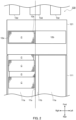
- FIG. 2 is a plan view of the stacker 111 and the picker 121.
- a plurality of coin rolls C are stored in a storage space 11a of the stacker 111.
- Each of the coin rolls C is composed of a plurality of coins piled in one direction in a layered manner.
- the coin piling direction corresponds to the left-right direction of the coin roll unit 10, i.e., a direction that is orthogonal to the direction in which the coin roll C is moved and is parallel to the horizontal direction.
- the length of each of the coin rolls C stored in the stacker 111 is smaller than the length of the stacker 111 along the coin piling direction (i.e., the length in the left-right direction).
- the in-stacker restriction member 11b having an opposing surface 11s being a flat surface facing the bottom surface of the coin roll C is attached to the storage space 11a, the position of the coin roll C in the stacker 111 in the left-right direction is restricted. That is, by attaching the in-stacker restriction member 11b, it is possible to prevent the coin roll C from shifting in the storage space 11a in the left-right direction. It is thus possible to move the coin roll C straight forward.
- the in-stacker restriction member 11b may be configured to be attachable in the storage space 11a at any position in the left-right direction depending on the length of the coin roll C.
- the stacker 111 may be configured such that the in-stacker restriction member 11b is attachable in the storage space 11a at any position. With such a configuration of the stacker 111, it is possible to move the coin roll C forward regardless of the length of the coin roll C without shifting of the coin roll C in the left-right direction.
- the stacker 111 may be configured such that various in-stacker restriction members of different sizes are attachable to the storage space 11a, instead of being configured such that the in-stacker restriction member 11b is attachable in the storage space 11a at any position in the left-right direction.
- a block member completely filling the space from the left side wall of the stacker 111 to the opposing surface 11s illustrated in FIG. 2 may be used as the in-stacker restriction member.
- the stacker 111 may be configured such that a block member longer than the in-stacker restriction member in the left-right direction is used as a long in-stacker position restriction member, a block member shorter than the in-stacker position restriction member in the left-right direction is used as a short in-stacker position restriction member, and one selected from these three members is attachable in the storage space 11a. Also with such a configuration of the stacker 111, it is possible to move the coin roll C forward regardless of the length of the coin roll C without shifting of the coin roll C in the left-right direction.
- the number of in-stacker restriction members having different lengths in the left-right direction may be 2, or may be 4 or more.
- the length of the coin roll C transferred by the picker 121 is less than the length of the picker 121 along the coin piling direction (i.e., the length in the left-right direction).
- the in-picker restriction member 12b having an opposing surface 12s being a flat surface facing the bottom surface of the coin roll C is attached to the groove 12a, the position of the coin roll C in the picker 121 in the left-right direction is restricted. That is, by attaching the in-picker restriction member 12b, it is possible to prevent the coin roll C from shifting in the groove 12a in the left-right direction. It is thus possible to move the coin roll C straight forward.
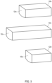
- FIG. 3 is a perspective view of three in-picker restriction members having different lengths in the coin piling direction.
- One of the members illustrated on the upper side of FIG. 3 is the in-picker restriction member 12b illustrated in FIG. 2 .
- One of the members illustrated in the middle of FIG. 3 is a long in-picker restriction member 12c that is longer than the in-picker restriction member 12b in the coin piling direction.
- One of the members illustrated on the lower side of FIG. 3 is a short in-picker restriction member 12d that is shorter than the in-picker restriction member 12b in the coin piling direction.
- the picker 121 may be configured such that a selected one of the three members is attachable in the groove 12a. With such a configuration of the picker 121, it is possible to move the coin roll C forward regardless of the length of the coin roll C without shifting of the coin roll C in the left-right direction.
- the number of in-picker restriction members having different lengths in the left-right direction may be 2, or may be 4 or more.
- the picker 121 may be configured such that one in-picker restriction member is attachable in the groove 12a at any position in the coin piling direction (i.e., in the left-right direction) depending on the length of the coin roll C, instead of being configured such that the various picker restriction members of different sizes are attachable to the groove 12a.
- the in-picker restriction member 12b may be configured to be attachable at a position on the right side of the position illustrated in FIG. 2 .
- the coin roll C moves from the stacker 111 to the lift 130 in a state where the positional shift of the coin roll C in the left-right direction is prevented.
- the coin roll C moves from the stacker 111 to the lift 130, with the face or the back of a coin being oriented in the left-right direction.
- the stacker 111 guides the coin roll C in the front-rear direction with the inner surface of one side wall of the stacker 111 and the opposing surface 11s of the in-stacker restriction member 11b.
- the stacker 111 moves the coin roll C from the rear side to the front side in the storage space 11a in a state where the positional shift of the coin roll C in the left-right direction is prevented.
- the picker 121 surrounds the coin roll C with the opposing surface 12s of the in-picker restriction member 12b and the inner surface of the groove 12a, so as to prevent the coin roll C from shifting in the left-right direction in the groove 12a.
- the picker 121 transfers the coin roll C in a state where the positional shift of the coin roll C in the left-right direction is prevented.
- the lift 130 supports the coin roll C as if to hold the coin roll C at a sharp angle portion formed by the belt 13c and the upper surface of the pawl member 13d.
- the lift 130 transports the coin roll C in a state where the positional shift of the coin roll C in the left-right direction is prevented.
- the opposing surface 11s of the in-stacker restriction member 11b and the opposing surface 12s of the in-picker restriction member 12b guides the coin roll C in a direction orthogonal to the piling direction of the coin roll C (i.e., the front-rear direction).
- the in-stacker restriction member 11b and the in-picker restriction member 12b such that their opposing surfaces 11s and 12s are included in a single plane, it is possible to smoothly move the coin roll C from the stacker 111 to the picker 121. In other words, it is possible to prevent the coin roll C from being caught by the stacker 111, the in-stacker restriction member 11b, the picker 121, or the in-picker restriction member 12b when the picker 121 takes in the coin roll C.
- the opposing surface 11s of the in-stacker restriction member 11b and the opposing surface 12s of the in-picker restriction member 12b are present at a position corresponding in the left-right direction to one of the pawl members 13d receiving the coin roll C (see the dotted line). That is, the coin roll C is moved from the stacker 111 to the lift 130 along the position corresponding to the opposing surface 11s of the in-stacker restriction member 11b, the opposing surface 12s of the in-picker restriction member 12b, and the pawl member 13d.
- the coin roll C in the stacker 111 is moved to the lift 130, the coin roll C is moved while the in-stacker restriction member 11b and the in-picker restriction member 12b prevent an increase in spacing between, on one hand, one end (right end) of the stacker 111 and one end (right end) of the picker 121 and, on the other hand, the coin roll C. Consequently, the coin roll C can be appropriately moved from the stacker 111 to the two pawl members 13d of the lift 130 on the right side.
- FIG. 2 illustrates a state in which the coin roll C is kept to the left by the in-stacker restriction member 11b and the in-picker restriction member 12b in the stacker 111 and the picker 121.
- the coin roll C may be kept to the right by the in-stacker restriction member 11b and the in-picker restriction member 12b.
- FIG. 4 is a schematic side view of the coin roll unit 10 according to Embodiment 2.
- the description of the contents common to Embodiments 1 and 2 may be omitted.
- the coin roll unit 10 comprises a recognition section 140, a reject section 150, and a dispensing section 160.
- the recognition section 140 is disposed in the middle of the transport path for transportation of the coin roll by the lift 130, and recognizes the coin roll being transported by the lift 130.
- the reject section 150 is disposed to face the lift 130. In a case that the result of recognition by the recognition section 140 indicates that the recognized coin roll is not to be dispensed, the coin roll is passed from the lift 130 to the reject section 150 and stored in the reject section 150. In a case that the result of recognition by the recognition section 140 indicates that the recognized coin roll is to be dispensed, the coin roll is transported by the lift 130 to the dispensing section 160.
- the coin roll unit 10 according to Embodiment 2 comprises a plurality of sets of stackers and pickers (six sets in the example illustrated in FIG. 4 ).
- the coin roll unit 10 comprises the stacker 111, a second stacker 112, a third stacker 113, a fourth stacker 114, a fifth stacker 115, and a sixth stacker 116 that are disposed to overlap one another in the upper-lower direction.
- Each of the stacker 111 and the second to the sixth stackers 112 to 116 is configured the same as the stacker 111 in Embodiment 1. That is, each of the stackers comprises an in-stacker restriction member configured the same as the in-stacker restriction member 11b in Embodiment 1. It is, however, needless to say that in each of the stackers, each in-stacker restriction member is attached to a position different depending on the length of the coin roll C to be stored in the stacker.
- the coin roll unit 10 comprises the picker 121, a second picker 122, a third picker 123, a fourth picker 124, a fifth picker 125, and a sixth picker 126.
- Each of the picker 121 and the second to the sixth pickers 122 to 126 is configured the same as the picker 121 in Embodiment 1. That is, each of the pickers comprises an in-picker restriction member configured the same as the in-picker restriction member 12b in Embodiment 1. It is, however, needless to say that in each of the pickers, each in-picker restriction member is attached to a position different depending on the length of the coin roll C to be transferred by the picker.
- Each of the stackers stores coin rolls of a type different between the stackers (e.g., different in denomination of piled coins and/or in length of a coin roll).
- the second stacker 112 stores a second coin roll.
- the second coin roll differs from the coin roll stored in the stacker 111 in length along the coin piling direction.
- the second picker 122 transfers the second coin roll from the second stacker 112 to the lift 130.
- Coin rolls stored in the other stackers are similarly transferred to the lift 130.
- the in-stacker restriction member that the second stacker 112 comprises (hereinafter, referred to as a second in-stacker restriction member) restricts the position of the second coin roll in the left-right direction (coin piling direction) in the second stacker 112.
- the in-picker restriction member that the second picker 122 comprises (hereinafter, referred to as a second in-picker restriction member) restricts the position of the second coin roll in the left-right direction (coin piling direction) in the second picker 122.
- the coin roll unit 10 according to the present embodiment is capable of transferring the coin roll from the stacker 111 to the lift 130 via the picker 121 without the coin roll being shifted in the coin piling direction.
- the coin roll unit 10 according to the present embodiment is capable of transferring the second coin roll, which is different from the coin roll in length in the coin piling direction, from the second stacker 112 to the lift 130 via the second picker 122 without the second coin roll being shifted in the coin piling direction.
- the coin roll unit 10 according to the present embodiment is capable of transferring the third to the sixth coin rolls, which are different from the coin roll and the second coin roll in length in the coin piling direction, to the lift 130 without the coin rolls being shifted in the coin piling direction. That is, the coin roll unit 10 according to the present embodiment is capable of smoothly processing various coin rolls without clogging in course of movement of the coin rolls.
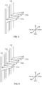
- FIG. 5 schematically illustrates one aspect of the lift 130.
- the lift 130 comprises two belts as belts 13c, that is, a first belt 131 and a second belt 132.
- a plurality of first pawl members 131a for supporting the coin roll C are attached to the first belt 131.
- a plurality of second pawl members 132a for supporting the coin roll C are attached to the second belt 132.
- the first pawl members 131a and the second pawl members 132a are disposed at substantially the same heights.
- the lift 130 is configured such that the first pawl members 131a and the second pawl members 132a move in the upper-lower direction while aligned in the horizontal direction (that is, in the left-right direction).
- FIG. 6 schematically illustrates another aspect of the lift 130.
- the lift 130 comprises three belts as belts 13c, that is, the first belt 131, the second belt 132, and a third belt 133.
- the second belt 132 is disposed to be sandwiched between the first belt 131 and the third belt 133.
- a plurality of third pawl members 133a for supporting the coin roll C are attached to the third belt 133.
- the lift 130 is configured such that the first pawl members 131a, the second pawl members 132a, and the third pawl members 133a move in the upper-lower direction while aligned in the horizontal direction (that is, in the left-right direction).
- the first belt 131 is disposed such that the first pawl members 131a are aligned with the right end of the picker 121 substantially in the front-rear direction.
- the second belt 132 is disposed such that the second pawl members 132a are aligned with the opposing surface 12s of the in-picker restriction member 12b substantially in the front-rear direction. Note that, this state is illustrated in FIG. 2 .
- the three pawl members 13d illustrated in FIG. 2 correspond to one of the first pawl members 131a, one of the second pawl members 132a, and one of the third pawl members 133a, respectively.
- the picker 121 is capable of transporting the coin roll C such that the right end side of the coin roll C is placed reliably on the first pawl member 131a and the left end side of the coin roll C is placed reliably on the second pawl member 132a, while restricting the position of the coin roll C by the in-picker restriction member 12b.
- the lift 130 comprises the third belt 133. Therefore, even in a case that the left end of the coin roll C protrudes by a long distance from the left end of the second pawl member 132a in a state where the right side portion of the coin roll C is placed on the first pawl member 131a, the protruding portion can be placed on the third pawl member 133a. Therefore, the lift 130 is capable of reliably transporting a long coin roll C by the three pawl members without dropping the long coin roll C.
- the in-picker restriction member 12b or the short in-picker restriction member 12d is attached to the picker 121 such that the opposing surface 12s is aligned with the third pawl member 133a substantially in the longitudinal direction, or is positioned on the left side of the third pawl member 133a.
- a spacing between the second belt 132 and the first belt 131 may be narrowed to some extent.
- the spacing between the second belt 132 and the first belt 131 may be smaller than a spacing between the second belt 132 and the third belt 133.
- the spacing between the second belt 132 and the first belt 131 may be shorter than half of the length of the coin roll C that is the longest of the lengths of the various coin rolls C that can be processed by the coin roll unit 10 (in other words, may be shorter than half of the length of the groove 12a of the picker 12). The effect will be described below.
- the coin roll C drops between the first pawl member 131a and the second pawl member 132a.
- the second pawl member 132a is inclined such that its right side is lowered due to the weight of the coin roll C, because the second belt 132 has flexibility.
- the gap between the first pawl member 131a and the second pawl member 132a widens and the left end of the coin roll C slides on the second pawl member 132a, and consequently, the coin roll C drops between the first pawl member 131a and the second pawl member 132a.
- the left end of the coin roll C is closer to the left end of the second pawl member 132a than to the right end of the second pawl member 132a. That is, the left end portion of the coin roll C can be supported in a wider range of the second pawl member 132a. Therefore, the left end of the coin roll C does not come off the second pawl member 132a.
- the second pawl member 132a does not incline such that its right side is lowered. So, it is possible to prevent the coin roll C from dropping between the first pawl member 131a and the second pawl member 132a.
- FIG. 7 is a perspective view illustrating a still another aspect of the lift 130.
- the lift 130 illustrated in FIG. 7 differs from the lift 130 illustrated in FIG. 6 in that the lift 130 illustrated in FIG. 7 comprises gap restriction members 135.
- Each of the gap restriction members 135 is a member for preventing the attitudes of the first pawl member 131a and the second pawl member from changing. There are no particular limitations on the material and shape of the member as long as it has such a function.
- the gap restriction member 135 is a platelike member comprising a through hole through which the first pawl member 131a can pass and a through hole through which the second pawl member 132a can pass.
- the gap restriction member 135 is configured to be engaged with the bases of the first pawl member 131a and the second pawl member 132a.
- the gap restriction member 135 has a shape that does not make contact with the coin roll C supported by the first pawl member 131a and the second pawl member 132a when the gap restriction member 135 is positioned at the bases of the first pawl member 131a and the second pawl member 132a. Therefore, the gap restriction member 135 does not adversely affect the transportation of the coin roll C by the lift 130.
- the lift 130 comprises the gap restriction member 135, it is possible to prevent the attitudes of the first pawl member 131a and the second pawl member from changing. Therefore, even when the left end of the coin roll C is positioned between the right end of the second pawl member 132a and the middle of the second pawl member 132a in the left-right direction, it is possible to prevent the second pawl member 132a from being inclined such that its right side is lowered due to the weight of the coin roll C, and to prevent the gap between the first pawl member 131a and the second pawl member 132a from being widened. It is thus possible to reliably prevent the coin roll C from dropping between the first pawl member 131a and the second pawl member 132a.
- the gap restriction member 135 may be configured to be attachable to and detachable from the first belt 131 and the second belt 132. With this configuration, it is possible to attach the gap restriction member 135 to a place where the gap restriction member is required and when necessary (for example, when a short coin roll C is processed by the coin roll unit 10). Further, when performing maintenance of the lift 130, it is possible to remove the gap restriction member 135. Therefore, it is not necessary to treat the first belt 131 and the second belt 132 integrally. Accordingly, maintainability is improved.
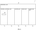
- FIG. 8 schematically illustrates a medium processing device 1, which is one of applications of the coin roll unit 10.
- the medium processing device 1 comprises the coin roll unit 10, a bill unit 20, a check unit 30, a loose coin unit 40, a controller 50, and a peripheral unit 60.
- the coin roll unit 10 is configured the same as described above.
- the coin roll unit 10 comprises the dispensing section 160 on the front surface.
- the bill unit 20 processes bills.
- the check unit 30 processes checks.
- the loose coin unit 40 processes loose coins.
- the controller 50 controls the coin roll unit 10, the bill unit 20, the check unit 30, and the loose coin unit 40.
- the peripheral unit 60 comprises a card reader, a printer, a display that provides information to a user of the medium processing device 1, an Encrypting PIN Pad (EPP) that receives an operation from the user, and the like.
- the peripheral unit 60 transmits, to the controller 50, a signal based on the operation received from the user.
- the controller 50 controls the coin roll unit 10, the bill unit 20, the check unit 30, the loose coin unit 40, and the peripheral unit 60 based on the signal received from the peripheral unit 60.
- the user inputs the type of needed coin roll (e.g., the denomination and number of coins constituting the coin roll) and the number of coin rolls via the peripheral unit 60.
- the controller 50 controls the coin roll unit 10 based on the input information.
- the stacker 111 storing the coin roll of the type requested by the user, the picker 121 constituting a set with the stacker 111, and the lift 130 are actuated to move the coin roll C from the stacker 111 to the dispensing section 160.
- the medium processing device 1 in particular, the coin roll unit 10 is capable of dispensing the requested number of coin rolls of the requested type as requested by the user.
- the present disclosure is utilizable as a coin roll unit used in various industrial fields such as distribution, finance, and the like.
Landscapes
- Physics & Mathematics (AREA)
- General Physics & Mathematics (AREA)
Abstract
Description
- The present disclosure relates to a coin roll unit.
- Conventionally, coins are handled in the form of a coin roll. The coin roll is a plurality of coins stacked into a columnar shape. A coin roll unit is used as a device for processing such a coin roll. The coin roll unit is disclosed in, for example, Patent Literature (hereinafter, referred to as "PTL") 1.
- PTL 1
WO2010/035332 - The length of the coin roll (i.e., the height of a column) can be various values depending on the number of coins to be stacked. In order for the coin roll unit to process coin rolls of various lengths, it is necessary to smoothly move the coin rolls inside the coin roll unit in spite of the lengths of the coin rolls.
- An object of the present disclosure is to provide a coin roll unit capable of processing coin rolls of various lengths.
- A coin roll unit according to the present disclosure comprises: a stacker that stores a coin roll composed of a plurality of coins piled in a piling direction in a layered manner; a lift that transports the coin roll; and a picker that transfers the coin roll from the stacker to the lift, characterized in that the picker comprises an in-picker restriction member that restricts a position of the coin roll in the picker in the piling direction.
- The picker that the coin roll unit according to the present disclosure comprises may be configured such that the in-picker restriction member is attachable to the picker at any position in the picker in the piling direction.
- The picker that the coin roll unit according to the present disclosure comprises may be configured such that a long in-picker restriction member or a short in-picker restriction member instead of the in-picker restriction member is attachable, the long in-picker restriction member being longer than the in-picker restriction member in the piling direction, the short in-picker restriction member being shorter than the in-picker restriction member in the piling direction.
- The stacker that the coin roll unit according to the present disclosure comprises may comprise an in-stacker restriction member that restricts a position of the coin roll in the stacker in the piling direction.
- The stacker that the coin roll unit according to the present disclosure comprises may be configured such that the in-stacker restriction member is attachable to the stacker at any position in the stacker in the piling direction.
- The stacker that the coin roll unit according to the present disclosure comprises may be configured such that a long in-stacker restriction member or a short in-stacker restriction member instead of the in-stacker restriction member is attachable, the long in-stacker restriction member being longer than the in-stacker restriction member in the piling direction, the short in-stacker restriction member being shorter than the in-stacker restriction member in the piling direction.
- The in-picker restriction member and the in-stacker restriction member that the coin roll unit according to the present disclosure comprises respectively have opposing surfaces facing the coin roll and included in a same plane, and the opposing surface of the in-picker restriction member and the opposing surface of the in-stacker restriction member may be configured to guide the coin roll in a direction orthogonal to the piling direction.
- The coin roll may be composed of a plurality of coins stacked in a columnar shape.
- The picker that the coin roll unit according to the present disclosure comprises may be configured to take in the coin roll from the stacker and transfer the coin roll such that the coin roll taken in is passed to the lift, in a state in which a bottom surface of the coin roll faces sideways.
- The coin roll unit according to the present disclosure may further comprise: a second stacker that stores a second coin roll composed of a plurality of second coins piled in the piling direction, the second coin roll having a length different from a length of the coin roll in the piling direction; and a second picker that transfers the second coin roll from the second stacker to the lift, in which the second picker comprises a second in-picker restriction member that restricts a position of the second coin roll in the second picker in the piling direction, the lift is configured to transport the second coin roll, and the stacker and the second stacker may be disposed to overlap each other in an upper-lower direction.
- The lift that the coin roll unit according to the present disclosure comprises may comprise: a first belt to which a first pawl member for supporting the coin roll is attached, and a second belt to which a second pawl member for supporting the coin roll with the first pawl member is attached, and may be configured to move the first pawl member and the second pawl member in an upper-lower direction in a state in which the first pawl member and the second pawl member are aligned in a horizontal direction.
- The lift that the coin roll unit according to the present disclosure comprises may further comprise a third belt to which a third pawl member for supporting the coin roll with the first pawl member and the second pawl member is attached, and may be configured to move the first pawl member, the second pawl member, and the third pawl member in the upper-lower direction in a state in which the first pawl member, the second pawl member, and the third pawl member are aligned in the horizontal direction, the second belt is sandwiched between the first belt and the third belt, and the in-picker restriction member may be configured to restrict the position of the coin roll in the picker such that, in plan view, the coin roll being transported by the picker faces the first belt and the second belt and does not face the third belt.
- A spacing between the second belt and the first belt that the coin roll unit according to the present disclosure comprises may be smaller than a spacing between the second belt and the third belt.
- The lift that the coin roll unit according to the present disclosure comprises may further comprise a gap restriction member that prevents a gap between the first pawl member and the second pawl member from widening.
- The gap restriction member that the coin roll unit according to the present disclosure comprises may be configured to be attachable to and detachable from the first belt and the second belt.
- The gap restriction member that the coin roll unit according to the present disclosure comprises may be configured to be not in contact with the coin roll supported by the first pawl member and the second pawl member, and to be engaged with the first pawl member and the second pawl member.
- According to the present disclosure, it is possible to provide a coin roll unit capable of processing coin rolls of various lengths.
-
-
FIG. 1 is a schematic side view of a coin roll unit according to Embodiment 1; -
FIG. 2 is a plan view of a stacker and a picker; -
FIG. 3 is a perspective view of an in-picker restriction member, a long in-picker restriction member, and a short in-picker restriction member; -
FIG. 4 is a schematic side view of a coin roll unit according to Embodiment 2; -
FIG. 5 schematically illustrates one aspect of a lift; -
FIG. 6 schematically illustrates one aspect of the lift; -
FIG. 7 schematically illustrates one aspect of the lift comprising a gap restriction member; and -
FIG. 8 schematically illustrates a medium processing device comprising a coin roll unit. - Hereinafter, an embodiment of the present disclosure will be described in detail with reference to the accompanying drawings. Note that, in the present specification, components or concepts provided with ordinal numbers such as "first," "second," and the like, e.g., a "first stacker" are described, but these ordinal numbers are merely for convenience and for making it easier to distinguish between a plurality of the same or similar components or concepts. Therefore, in some cases, a component or concept provided with the ordinal number "first" and a component or concept provided with the ordinal number "second" can be read interchangeably.
-
FIG. 1 is a schematic side view of acoin roll unit 10 according to Embodiment 1. In the present embodiment, the front side of thecoin roll unit 10 is the side on which a coin roll take-out port is disposed, and the rear side of thecoin roll unit 10 is the side on which astacker 111 to be described later is disposed. Inside thecoin roll unit 10, a coin roll moves from the rear side toward the front side. Further, the right side of thecoin roll unit 10 is the right side of thecoin roll unit 10 seen from the front side, and the left side of thecoin roll unit 10 is the left side of thecoin roll unit 10 seen from the front side. Further, the lower side of thecoin roll unit 10 is a side near the surface at which thecoin roll unit 10 is installed, and the upper side of thecoin roll unit 10 is a side far from the surface at which thecoin roll unit 10 is installed. - The
coin roll unit 10 is a device for processing a coin roll C, and comprises astacker 111, apicker 121, and alift 130. - The coin roll C is composed of a plurality of coins piled in a columnar shape. The coin roll C may be wrapped in a sheet of plastic film, paper, or the like. A plurality of coin rolls C having the same shape are stored in the
stacker 111. That is, each of the plurality of coin rolls C stored in thestacker 111 is composed of the same number of stacked coins of the same type (denomination). Naturally, the heights of the plurality of coin rolls C stored in thestacker 111 are equal to one another. - The
stacker 111 is a tray-shaped member for storing a plurality of coin rolls C. Thestacker 111 stores the coin rolls C, with the bottom surfaces of the coin rolls C (i.e., the faces or the backs of the coins) facing sideways (the right side or left side). Thestacker 111 may be disposed such that its front side is lower and its rear side is higher. With such an arrangement, it is possible to automatically move the coin rolls C stored in thestacker 111 to the front side by gravity. Note that, one coin roll C may be placed on top of another coin roll C. - The front end of the
stacker 111 is configured to allow the coin rolls C to pass therethrough. For example, an opening is formed in the front end, or the front end is completely open without any wall. After passing through the front end of thestacker 111, the coin rolls in thestacker 111 moves to thepicker 121. - The
picker 121 takes in each of the coin rolls C from thestacker 111 and transfers the coin roll such that the coin roll C taken in is passed to thelift 130, in a state in which the bottom surface of the coin roll C faces sideways. Thepicker 121 is a member that rotates about a rotation axis extending in the left-right direction (specifically, the horizontal direction). Thepicker 121 is configured to rotate counterclockwise in a right side view by the power of a motor or the like. At least onegroove 12a (three grooves in the example ofFIG. 1 ) is formed in the peripheral surface of thepicker 121. One coin roll enters onegroove 12a. When moving from thestacker 111 to thepicker 121, the coin roll C enters thegroove 12a. - The coin roll C that has entered the
groove 12a is transferred by thepicker 121 to thelift 130 disposed on the front side. - The
lift 130 is a conveyor that takes in the coin roll C from thepicker 121 and transports, to the take-out port, the coin roll C taken in, in a state where the bottom surface of the coin roll C faces sideways. Thelift 130 comprises afirst roller 13a disposed on the upper side, asecond roller 13b disposed on the lower side, and anendless belt 13c wound under tension around thefirst roller 13a and thesecond roller 13b. A plurality ofpawl members 13d are attached to thebelt 13c. Further, thelift 130 comprises apressing plate 13e extending vertically. Thepressing plate 13e is disposed to face thebelt 13c via a space. Note that thelift 130 does not have to comprise thepressing plate 13e. In this case, a housing of thecoin roll unit 10 may be configured to be capable of functioning as thepressing plate 13e. - At least one of the
first roller 13a and thesecond roller 13b is configured to rotate counterclockwise in the right side view by power of a motor or the like. Thebelt 13c is configured to move counterclockwise in the right side view by rotation of at least one of thefirst roller 13a and thesecond roller 13b. That is, a part of thebelt 13c located on the rear side ascends while a part located on the front side descends. - Pawl
members 13d are attached to thebelt 13c to be oblique with respect to thebelt 13c. Specifically, each of thepawl members 13d is attached to thebelt 13c such that the pawl member becomes higher toward the farther side from thebelt 13c when ascending with thebelt 13c and becomes lower toward the farther side from thebelt 13c when descending with thebelt 13c. - The coin roll C taken in from the
picker 121 to thelift 130 is received at an upper part of thepawl member 13d, and ascends while being supported by thebelt 13c and thepawl member 13d. The coin roll C having ascended falls on an immediately preceding one of thepawl members 13d as thebelt 13c turns around thefirst roller 13a. The coin roll C having fallen moves downward in the space between thepressing plate 13e and thebelt 13c. Then, when having moved down to a position below thepressing plate 13e, the coin roll C is released from being pressed by thepressing plate 13e. Accordingly, the coin roll C moves toward the take-out port for the coin roll C while rolling on thepawl member 13d. Details of thelift 130 will be described later. -
FIG. 2 is a plan view of thestacker 111 and thepicker 121. A plurality of coin rolls C are stored in astorage space 11a of thestacker 111. Each of the coin rolls C is composed of a plurality of coins piled in one direction in a layered manner. Inside thecoin roll unit 10, the coin piling direction corresponds to the left-right direction of thecoin roll unit 10, i.e., a direction that is orthogonal to the direction in which the coin roll C is moved and is parallel to the horizontal direction. - The length of each of the coin rolls C stored in the
stacker 111 is smaller than the length of thestacker 111 along the coin piling direction (i.e., the length in the left-right direction). The greater the difference between the length of the coin roll C and the length of thestacker 111 in the left-right direction, the more likely the coin roll C is to be shifted in the left-right direction in thestorage space 11a of thestacker 111. In a case that the in-stacker restriction member 11b having an opposingsurface 11s being a flat surface facing the bottom surface of the coin roll C is attached to thestorage space 11a, the position of the coin roll C in thestacker 111 in the left-right direction is restricted. That is, by attaching the in-stacker restriction member 11b, it is possible to prevent the coin roll C from shifting in thestorage space 11a in the left-right direction. It is thus possible to move the coin roll C straight forward. - The in-
stacker restriction member 11b may be configured to be attachable in thestorage space 11a at any position in the left-right direction depending on the length of the coin roll C. In other words, thestacker 111 may be configured such that the in-stacker restriction member 11b is attachable in thestorage space 11a at any position. With such a configuration of thestacker 111, it is possible to move the coin roll C forward regardless of the length of the coin roll C without shifting of the coin roll C in the left-right direction. - Note that, the
stacker 111 may be configured such that various in-stacker restriction members of different sizes are attachable to thestorage space 11a, instead of being configured such that the in-stacker restriction member 11b is attachable in thestorage space 11a at any position in the left-right direction. For example, a block member completely filling the space from the left side wall of thestacker 111 to the opposingsurface 11s illustrated inFIG. 2 may be used as the in-stacker restriction member. In addition, in this case, thestacker 111 may be configured such that a block member longer than the in-stacker restriction member in the left-right direction is used as a long in-stacker position restriction member, a block member shorter than the in-stacker position restriction member in the left-right direction is used as a short in-stacker position restriction member, and one selected from these three members is attachable in thestorage space 11a. Also with such a configuration of thestacker 111, it is possible to move the coin roll C forward regardless of the length of the coin roll C without shifting of the coin roll C in the left-right direction. The number of in-stacker restriction members having different lengths in the left-right direction may be 2, or may be 4 or more. - The length of the coin roll C transferred by the
picker 121 is less than the length of thepicker 121 along the coin piling direction (i.e., the length in the left-right direction). The greater the difference between the length of the coin roll C and the length of thepicker 121 in the left-right direction, the more likely the coin roll C is to be shifted in the left-right direction in thegroove 12a of thepicker 121. In a case that the in-picker restriction member 12b having an opposingsurface 12s being a flat surface facing the bottom surface of the coin roll C is attached to thegroove 12a, the position of the coin roll C in thepicker 121 in the left-right direction is restricted. That is, by attaching the in-picker restriction member 12b, it is possible to prevent the coin roll C from shifting in thegroove 12a in the left-right direction. It is thus possible to move the coin roll C straight forward. - The
picker 121 may be configured such that various in-picker restriction members of different sizes are attachable to thegroove 12a.FIG. 3 is a perspective view of three in-picker restriction members having different lengths in the coin piling direction. One of the members illustrated on the upper side ofFIG. 3 is the in-picker restriction member 12b illustrated inFIG. 2 . One of the members illustrated in the middle ofFIG. 3 is a long in-picker restriction member 12c that is longer than the in-picker restriction member 12b in the coin piling direction. One of the members illustrated on the lower side ofFIG. 3 is a short in-picker restriction member 12d that is shorter than the in-picker restriction member 12b in the coin piling direction. Thepicker 121 may be configured such that a selected one of the three members is attachable in thegroove 12a. With such a configuration of thepicker 121, it is possible to move the coin roll C forward regardless of the length of the coin roll C without shifting of the coin roll C in the left-right direction. The number of in-picker restriction members having different lengths in the left-right direction may be 2, or may be 4 or more. - Note that, the
picker 121 may be configured such that one in-picker restriction member is attachable in thegroove 12a at any position in the coin piling direction (i.e., in the left-right direction) depending on the length of the coin roll C, instead of being configured such that the various picker restriction members of different sizes are attachable to thegroove 12a. For example, in a case that a coin roll shorter than the coin roll C illustrated inFIG. 2 is processed, the in-picker restriction member 12b may be configured to be attachable at a position on the right side of the position illustrated inFIG. 2 . - The coin roll C moves from the
stacker 111 to thelift 130 in a state where the positional shift of the coin roll C in the left-right direction is prevented. In other words, the coin roll C moves from thestacker 111 to thelift 130, with the face or the back of a coin being oriented in the left-right direction. Thestacker 111 guides the coin roll C in the front-rear direction with the inner surface of one side wall of thestacker 111 and the opposingsurface 11s of the in-stacker restriction member 11b. Thus, thestacker 111 moves the coin roll C from the rear side to the front side in thestorage space 11a in a state where the positional shift of the coin roll C in the left-right direction is prevented. Thepicker 121 surrounds the coin roll C with the opposingsurface 12s of the in-picker restriction member 12b and the inner surface of thegroove 12a, so as to prevent the coin roll C from shifting in the left-right direction in thegroove 12a. Thus, thepicker 121 transfers the coin roll C in a state where the positional shift of the coin roll C in the left-right direction is prevented. Thelift 130 supports the coin roll C as if to hold the coin roll C at a sharp angle portion formed by thebelt 13c and the upper surface of thepawl member 13d. Thus, thelift 130 transports the coin roll C in a state where the positional shift of the coin roll C in the left-right direction is prevented. - The opposing
surface 11s of the in-stacker restriction member 11b and the opposingsurface 12s of the in-picker restriction member 12b guides the coin roll C in a direction orthogonal to the piling direction of the coin roll C (i.e., the front-rear direction). By disposing the in-stacker restriction member 11b and the in-picker restriction member 12b such that their opposingsurfaces stacker 111 to thepicker 121. In other words, it is possible to prevent the coin roll C from being caught by thestacker 111, the in-stacker restriction member 11b, thepicker 121, or the in-picker restriction member 12b when thepicker 121 takes in the coin roll C. - In the example of
FIG. 2 , the opposingsurface 11s of the in-stacker restriction member 11b and the opposingsurface 12s of the in-picker restriction member 12b are present at a position corresponding in the left-right direction to one of thepawl members 13d receiving the coin roll C (see the dotted line). That is, the coin roll C is moved from thestacker 111 to thelift 130 along the position corresponding to the opposingsurface 11s of the in-stacker restriction member 11b, the opposingsurface 12s of the in-picker restriction member 12b, and thepawl member 13d. In other words, when the coin roll C in thestacker 111 is moved to thelift 130, the coin roll C is moved while the in-stacker restriction member 11b and the in-picker restriction member 12b prevent an increase in spacing between, on one hand, one end (right end) of thestacker 111 and one end (right end) of thepicker 121 and, on the other hand, the coin roll C. Consequently, the coin roll C can be appropriately moved from thestacker 111 to the twopawl members 13d of thelift 130 on the right side. -
FIG. 2 illustrates a state in which the coin roll C is kept to the left by the in-stacker restriction member 11b and the in-picker restriction member 12b in thestacker 111 and thepicker 121. However, in thestacker 111 and thepicker 121, the coin roll C may be kept to the right by the in-stacker restriction member 11b and the in-picker restriction member 12b. -
FIG. 4 is a schematic side view of thecoin roll unit 10 according to Embodiment 2. Hereinafter, the description of the contents common to Embodiments 1 and 2 may be omitted. - The
coin roll unit 10 according to the present embodiment comprises arecognition section 140, areject section 150, and adispensing section 160. - The
recognition section 140 is disposed in the middle of the transport path for transportation of the coin roll by thelift 130, and recognizes the coin roll being transported by thelift 130. Thereject section 150 is disposed to face thelift 130. In a case that the result of recognition by therecognition section 140 indicates that the recognized coin roll is not to be dispensed, the coin roll is passed from thelift 130 to thereject section 150 and stored in thereject section 150. In a case that the result of recognition by therecognition section 140 indicates that the recognized coin roll is to be dispensed, the coin roll is transported by thelift 130 to thedispensing section 160. - The
coin roll unit 10 according to Embodiment 2 comprises a plurality of sets of stackers and pickers (six sets in the example illustrated inFIG. 4 ). - Specifically, the
coin roll unit 10 comprises thestacker 111, asecond stacker 112, athird stacker 113, afourth stacker 114, afifth stacker 115, and asixth stacker 116 that are disposed to overlap one another in the upper-lower direction. Each of thestacker 111 and the second to thesixth stackers 112 to 116 is configured the same as thestacker 111 in Embodiment 1. That is, each of the stackers comprises an in-stacker restriction member configured the same as the in-stacker restriction member 11b in Embodiment 1. It is, however, needless to say that in each of the stackers, each in-stacker restriction member is attached to a position different depending on the length of the coin roll C to be stored in the stacker. - The
coin roll unit 10 comprises thepicker 121, asecond picker 122, athird picker 123, afourth picker 124, afifth picker 125, and asixth picker 126. Each of thepicker 121 and the second to thesixth pickers 122 to 126 is configured the same as thepicker 121 in Embodiment 1. That is, each of the pickers comprises an in-picker restriction member configured the same as the in-picker restriction member 12b in Embodiment 1. It is, however, needless to say that in each of the pickers, each in-picker restriction member is attached to a position different depending on the length of the coin roll C to be transferred by the picker. - Each of the stackers stores coin rolls of a type different between the stackers (e.g., different in denomination of piled coins and/or in length of a coin roll). The
second stacker 112 stores a second coin roll. The second coin roll differs from the coin roll stored in thestacker 111 in length along the coin piling direction. Thesecond picker 122 transfers the second coin roll from thesecond stacker 112 to thelift 130. Coin rolls stored in the other stackers are similarly transferred to thelift 130. - The in-stacker restriction member that the
second stacker 112 comprises (hereinafter, referred to as a second in-stacker restriction member) restricts the position of the second coin roll in the left-right direction (coin piling direction) in thesecond stacker 112. The in-picker restriction member that thesecond picker 122 comprises (hereinafter, referred to as a second in-picker restriction member) restricts the position of the second coin roll in the left-right direction (coin piling direction) in thesecond picker 122. - Thus, the
coin roll unit 10 according to the present embodiment is capable of transferring the coin roll from thestacker 111 to thelift 130 via thepicker 121 without the coin roll being shifted in the coin piling direction. In addition, thecoin roll unit 10 according to the present embodiment is capable of transferring the second coin roll, which is different from the coin roll in length in the coin piling direction, from thesecond stacker 112 to thelift 130 via thesecond picker 122 without the second coin roll being shifted in the coin piling direction. Likewise, thecoin roll unit 10 according to the present embodiment is capable of transferring the third to the sixth coin rolls, which are different from the coin roll and the second coin roll in length in the coin piling direction, to thelift 130 without the coin rolls being shifted in the coin piling direction. That is, thecoin roll unit 10 according to the present embodiment is capable of smoothly processing various coin rolls without clogging in course of movement of the coin rolls. - Next, the configuration of the
lift 130 common to Embodiment 1 and Embodiment 2 will be described in detail. -
FIG. 5 schematically illustrates one aspect of thelift 130. In the aspect illustrated inFIG. 5 , thelift 130 comprises two belts asbelts 13c, that is, afirst belt 131 and asecond belt 132. A plurality offirst pawl members 131a for supporting the coin roll C are attached to thefirst belt 131. A plurality ofsecond pawl members 132a for supporting the coin roll C are attached to thesecond belt 132. Thefirst pawl members 131a and thesecond pawl members 132a are disposed at substantially the same heights. Thelift 130 is configured such that thefirst pawl members 131a and thesecond pawl members 132a move in the upper-lower direction while aligned in the horizontal direction (that is, in the left-right direction). -
FIG. 6 schematically illustrates another aspect of thelift 130. In the aspect illustrated inFIG. 6 , thelift 130 comprises three belts asbelts 13c, that is, thefirst belt 131, thesecond belt 132, and athird belt 133. Thesecond belt 132 is disposed to be sandwiched between thefirst belt 131 and thethird belt 133. A plurality ofthird pawl members 133a for supporting the coin roll C are attached to thethird belt 133. Thelift 130 is configured such that thefirst pawl members 131a, thesecond pawl members 132a, and thethird pawl members 133a move in the upper-lower direction while aligned in the horizontal direction (that is, in the left-right direction). - In the aspect illustrated in
FIGS. 5 and 6 , thefirst belt 131 is disposed such that thefirst pawl members 131a are aligned with the right end of thepicker 121 substantially in the front-rear direction. Thesecond belt 132 is disposed such that thesecond pawl members 132a are aligned with the opposingsurface 12s of the in-picker restriction member 12b substantially in the front-rear direction. Note that, this state is illustrated inFIG. 2 . The threepawl members 13d illustrated inFIG. 2 correspond to one of thefirst pawl members 131a, one of thesecond pawl members 132a, and one of thethird pawl members 133a, respectively. - Therefore, the
picker 121 is capable of transporting the coin roll C such that the right end side of the coin roll C is placed reliably on thefirst pawl member 131a and the left end side of the coin roll C is placed reliably on thesecond pawl member 132a, while restricting the position of the coin roll C by the in-picker restriction member 12b. - Further, in the aspect illustrated in
FIG. 6 , thelift 130 comprises thethird belt 133. Therefore, even in a case that the left end of the coin roll C protrudes by a long distance from the left end of thesecond pawl member 132a in a state where the right side portion of the coin roll C is placed on thefirst pawl member 131a, the protruding portion can be placed on thethird pawl member 133a. Therefore, thelift 130 is capable of reliably transporting a long coin roll C by the three pawl members without dropping the long coin roll C. In the case of processing such a long coin roll C, the in-picker restriction member 12b or the short in-picker restriction member 12d is attached to thepicker 121 such that the opposingsurface 12s is aligned with thethird pawl member 133a substantially in the longitudinal direction, or is positioned on the left side of thethird pawl member 133a. - A spacing between the
second belt 132 and thefirst belt 131 may be narrowed to some extent. For example, the spacing between thesecond belt 132 and thefirst belt 131 may be smaller than a spacing between thesecond belt 132 and thethird belt 133. Alternatively, the spacing between thesecond belt 132 and thefirst belt 131 may be shorter than half of the length of the coin roll C that is the longest of the lengths of the various coin rolls C that can be processed by the coin roll unit 10 (in other words, may be shorter than half of the length of thegroove 12a of the picker 12). The effect will be described below. - If the left end of the coin roll C is positioned near the right end of the
second pawl member 132a while the coin roll C is being transported by thelift 130, there is a possibility that the coin roll C is shifted rightward by some vibration and the left end of the coin roll C comes off thesecond pawl member 132a. In this case, the coin roll C drops between thefirst pawl member 131a and thesecond pawl member 132a. Further, when the left end of the coin roll C is positioned between the right end of thesecond pawl member 132a and the middle of thesecond pawl member 132a in the left-right direction, there is a possibility that thesecond pawl member 132a is inclined such that its right side is lowered due to the weight of the coin roll C, because thesecond belt 132 has flexibility. When such inclination occurs, there is a possibility that the gap between thefirst pawl member 131a and thesecond pawl member 132a widens and the left end of the coin roll C slides on thesecond pawl member 132a, and consequently, the coin roll C drops between thefirst pawl member 131a and thesecond pawl member 132a. - However, by reducing the spacing between the
second belt 132 and thefirst belt 131, it is possible to position the left end of the coin roll C closer to the left end of thesecond pawl member 132a than to the right end of thesecond pawl member 132a. That is, the left end portion of the coin roll C can be supported in a wider range of thesecond pawl member 132a. Therefore, the left end of the coin roll C does not come off thesecond pawl member 132a. Thesecond pawl member 132a does not incline such that its right side is lowered. So, it is possible to prevent the coin roll C from dropping between thefirst pawl member 131a and thesecond pawl member 132a. -
FIG. 7 is a perspective view illustrating a still another aspect of thelift 130. Thelift 130 illustrated inFIG. 7 differs from thelift 130 illustrated inFIG. 6 in that thelift 130 illustrated inFIG. 7 comprisesgap restriction members 135. - Each of the
gap restriction members 135 is a member for preventing the attitudes of thefirst pawl member 131a and the second pawl member from changing. There are no particular limitations on the material and shape of the member as long as it has such a function. In the example illustrated inFIG. 7 , thegap restriction member 135 is a platelike member comprising a through hole through which thefirst pawl member 131a can pass and a through hole through which thesecond pawl member 132a can pass. Thegap restriction member 135 is configured to be engaged with the bases of thefirst pawl member 131a and thesecond pawl member 132a. Thegap restriction member 135 has a shape that does not make contact with the coin roll C supported by thefirst pawl member 131a and thesecond pawl member 132a when thegap restriction member 135 is positioned at the bases of thefirst pawl member 131a and thesecond pawl member 132a. Therefore, thegap restriction member 135 does not adversely affect the transportation of the coin roll C by thelift 130. - When the
lift 130 comprises thegap restriction member 135, it is possible to prevent the attitudes of thefirst pawl member 131a and the second pawl member from changing. Therefore, even when the left end of the coin roll C is positioned between the right end of thesecond pawl member 132a and the middle of thesecond pawl member 132a in the left-right direction, it is possible to prevent thesecond pawl member 132a from being inclined such that its right side is lowered due to the weight of the coin roll C, and to prevent the gap between thefirst pawl member 131a and thesecond pawl member 132a from being widened. It is thus possible to reliably prevent the coin roll C from dropping between thefirst pawl member 131a and thesecond pawl member 132a. - The
gap restriction member 135 may be configured to be attachable to and detachable from thefirst belt 131 and thesecond belt 132. With this configuration, it is possible to attach thegap restriction member 135 to a place where the gap restriction member is required and when necessary (for example, when a short coin roll C is processed by the coin roll unit 10). Further, when performing maintenance of thelift 130, it is possible to remove thegap restriction member 135. Therefore, it is not necessary to treat thefirst belt 131 and thesecond belt 132 integrally. Accordingly, maintainability is improved. -
FIG. 8 schematically illustrates a medium processing device 1, which is one of applications of thecoin roll unit 10. The medium processing device 1 comprises thecoin roll unit 10, abill unit 20, acheck unit 30, aloose coin unit 40, acontroller 50, and aperipheral unit 60. - The
coin roll unit 10 is configured the same as described above. Thecoin roll unit 10 comprises thedispensing section 160 on the front surface. Thebill unit 20 processes bills. Thecheck unit 30 processes checks. Theloose coin unit 40 processes loose coins. Thecontroller 50 controls thecoin roll unit 10, thebill unit 20, thecheck unit 30, and theloose coin unit 40. Theperipheral unit 60 comprises a card reader, a printer, a display that provides information to a user of the medium processing device 1, an Encrypting PIN Pad (EPP) that receives an operation from the user, and the like. Theperipheral unit 60 transmits, to thecontroller 50, a signal based on the operation received from the user. Thecontroller 50 controls thecoin roll unit 10, thebill unit 20, thecheck unit 30, theloose coin unit 40, and theperipheral unit 60 based on the signal received from theperipheral unit 60. - For example, the user inputs the type of needed coin roll (e.g., the denomination and number of coins constituting the coin roll) and the number of coin rolls via the
peripheral unit 60. Thecontroller 50 controls thecoin roll unit 10 based on the input information. Specifically, thestacker 111 storing the coin roll of the type requested by the user, thepicker 121 constituting a set with thestacker 111, and thelift 130 are actuated to move the coin roll C from thestacker 111 to thedispensing section 160. By such an operation, the medium processing device 1, in particular, thecoin roll unit 10 is capable of dispensing the requested number of coin rolls of the requested type as requested by the user. - The present disclosure is utilizable as a coin roll unit used in various industrial fields such as distribution, finance, and the like.
-
- 10 Coin roll unit
- 111 Stacker
- 11a Storage space
- 11b In-stacker restriction member
- 11s Opposing surface
- 112 Second stacker
- 113 Third stacker
- 114 Fourth stacker
- 115 Fifth stacker
- 116 Sixth stacker
- 121 Picker
- 12a Groove
- 12b In-picker restriction member
- 12c Long in-picker restriction member
- 12d Short in-picker restriction member
- 12s Opposing surface
- 122 Second picker
- 123 Third picker
- 124 Fourth picker
- 125 Fifth picker
- 126 Sixth picker
- 130 Lift
- 13a First roller
- 13b Second roller
- 13c Belt
- 13d Pawl member
- 13e Pressing plate
- 131 First belt
- 132 Second belt
- 133 Third belt
- 131a First pawl member
- 132a Second pawl member
- 133a Third pawl member
- 134 Belt support member
- 135 Gap restriction member
- 140 Recognition section
- 150 Reject section
- 160 Dispensing section
- 1 Medium processing device
- 20 Bill unit
- 30 Check unit
- 40 Loose coin unit
- 50 Controller
- 60 Peripheral unit
- C Coin roll
Claims (15)
- A coin roll unit, comprising:a stacker that stores a coin roll composed of a plurality of coins piled in a piling direction in a layered manner;a lift that transports the coin roll; anda picker that transfers the coin roll from the stacker to the lift, characterized in thatthe picker comprises an in-picker restriction member that restricts a position of the coin roll in the picker in the piling direction.
- The coin roll unit according to claim 1, wherein
the picker is configured such that the in-picker restriction member is attachable to the picker at any position in the picker in the piling direction. - The coin roll unit according to claim 1 or 2, wherein
the picker is configured such that a long in-picker restriction member or a short in-picker restriction member instead of the in-picker restriction member is attachable, the long in-picker restriction member being longer than the in-picker restriction member in the piling direction, the short in-picker restriction member being shorter than the in-picker restriction member in the piling direction. - The coin roll unit according to any one of claims 1 to 3, wherein
the stacker comprises an in-stacker restriction member that restricts a position of the coin roll in the stacker in the piling direction. - The coin roll unit according to claim 4, wherein
the stacker is configured such that the in-stacker restriction member is attachable to the stacker at any position in the stacker in the piling direction. - The coin roll unit according to claim 4 or 5, wherein
the stacker is configured such that a long in-stacker restriction member or a short in-stacker restriction member instead of the in-stacker restriction member is attachable, the long in-stacker restriction member being longer than the in-stacker restriction member in the piling direction, the short in-stacker restriction member being shorter than the in-stacker restriction member in the piling direction. - The coin roll unit according to any one of claims 4 to 6, wherein:the in-picker restriction member has an opposing surface facing the coin roll in the picker,the in-stacker restriction member has an opposing surface facing the coin roll in the stacker, andthe opposing surface of the in-picker restriction member and the opposing surface of the in-stacker restriction member are configured to be located in a same plane and are configured to guide the coin roll in a direction orthogonal to the piling direction.
- The coin roll unit according to any one of claims 1 to 7, wherein:the coin roll is composed of a plurality of coins stacked in a columnar shape, andthe picker takes in the coin roll from the stacker and transfers the coin roll such that the coin roll taken in is passed to the lift, in a state in which a bottom surface of the coin roll faces sideways.
- The coin roll unit according to any one of claims 1 to 8, further comprising:a second stacker that stores a second coin roll composed of a plurality of second coins piled in the piling direction, the second coin roll having a length different from a length of the coin roll in the piling direction; anda second picker that transfers the second coin roll from the second stacker to the lift, whereinthe second picker comprises a second in-picker restriction member that restricts a position of the second coin roll in the second picker in the piling direction,the lift is configured to transport the second coin roll, andthe stacker and the second stacker are disposed to overlap each other in an upper-lower direction.
- The coin roll unit according to any one of claims 1 to 9, wherein:the lift comprises:a first belt to which a first pawl member for supporting the coin roll is attached, anda second belt to which a second pawl member for supporting the coin roll with the first pawl member is attached, andthe lift is configured to move the first pawl member and the second pawl member in an upper-lower direction in a state in which the first pawl member and the second pawl member are aligned in a horizontal direction.
- The coin roll unit according to claim 10, wherein:the lift further comprises a third belt to which a third pawl member for supporting the coin roll with the first pawl member and the second pawl member is attached,the lift is configured to move the first pawl member, the second pawl member, and the third pawl member in the upper-lower direction in a state in which the first pawl member, the second pawl member, and the third pawl member are aligned in the horizontal direction,the second belt is sandwiched between the first belt and the third belt, andthe in-picker restriction member restricts the position of the coin roll in the picker such that, in plan view, the coin roll being transported by the picker faces the first belt and the second belt and does not face the third belt.
- The coin roll unit according to claim 11, wherein
a spacing between the second belt and the first belt is smaller than a spacing between the second belt and the third belt. - The coin roll unit according to any one of claims 10 to 12, wherein
the lift further comprises a gap restriction member that prevents a gap between the first pawl member and the second pawl member from widening. - The coin roll unit according to claim 13, wherein
the gap restriction member is configured to be attachable to and detachable from the first belt and the second belt, - The coin roll unit according to claim 13 or 14, wherein
the gap restriction member is configured to be not in contact with the coin roll supported by the first pawl member and the second pawl member, and to be engaged with the first pawl member and the second pawl member.
Priority Applications (1)
| Application Number | Priority Date | Filing Date | Title |
|---|---|---|---|
| EP22169021.7A EP4266271B1 (en) | 2022-04-20 | 2022-04-20 | Coin roll unit |
Applications Claiming Priority (1)
| Application Number | Priority Date | Filing Date | Title |
|---|---|---|---|
| EP22169021.7A EP4266271B1 (en) | 2022-04-20 | 2022-04-20 | Coin roll unit |
Publications (2)
| Publication Number | Publication Date |
|---|---|
| EP4266271A1 true EP4266271A1 (en) | 2023-10-25 |
| EP4266271B1 EP4266271B1 (en) | 2024-12-25 |
Family
ID=81344479
Family Applications (1)
| Application Number | Title | Priority Date | Filing Date |
|---|---|---|---|
| EP22169021.7A Active EP4266271B1 (en) | 2022-04-20 | 2022-04-20 | Coin roll unit |
Country Status (1)
| Country | Link |
|---|---|
| EP (1) | EP4266271B1 (en) |
Citations (4)
| Publication number | Priority date | Publication date | Assignee | Title |
|---|---|---|---|---|
| DE9002363U1 (en) * | 1990-02-28 | 1990-05-17 | Hess-SB-Automatenbau GmbH, 7037 Magstadt | Device for dispensing cylindrical objects |
| SE517441C2 (en) * | 2000-10-05 | 2002-06-04 | Axlon Int Ab | Cash dispenser system with drive gearing consists of a rotary outputter for different denomination coins, with an anti-jamming assembly |
| US20160284151A1 (en) * | 2013-12-04 | 2016-09-29 | Glory Ltd. | Coin-roll ejecting device and money changer |
| US20170076529A1 (en) * | 2014-05-08 | 2017-03-16 | Glory Ltd. | Coin-roll ejecting device, money processing machine and coin-roll ejection method |
-
2022
- 2022-04-20 EP EP22169021.7A patent/EP4266271B1/en active Active
Patent Citations (4)
| Publication number | Priority date | Publication date | Assignee | Title |
|---|---|---|---|---|
| DE9002363U1 (en) * | 1990-02-28 | 1990-05-17 | Hess-SB-Automatenbau GmbH, 7037 Magstadt | Device for dispensing cylindrical objects |
| SE517441C2 (en) * | 2000-10-05 | 2002-06-04 | Axlon Int Ab | Cash dispenser system with drive gearing consists of a rotary outputter for different denomination coins, with an anti-jamming assembly |
| US20160284151A1 (en) * | 2013-12-04 | 2016-09-29 | Glory Ltd. | Coin-roll ejecting device and money changer |
| US20170076529A1 (en) * | 2014-05-08 | 2017-03-16 | Glory Ltd. | Coin-roll ejecting device, money processing machine and coin-roll ejection method |
Also Published As
| Publication number | Publication date |
|---|---|
| EP4266271B1 (en) | 2024-12-25 |
Similar Documents
| Publication | Publication Date | Title |
|---|---|---|
| CN101456495B (en) | Banknote handling apparatus | |
| EP0317537A2 (en) | Bill handling apparatus | |
| JP6072631B2 (en) | Paper sheet handling equipment | |
| JP2003157461A (en) | Bill depositing device | |
| RU2637897C1 (en) | Device for laying carriers and device of transactions with carriers | |
| JP2003160271A (en) | Bill receiving / dispensing device | |
| JP6591787B2 (en) | Automatic cash transaction equipment | |
| KR20150098553A (en) | Paper notes input output device | |
| CN103693487B (en) | Reduce the device and method of blocking | |
| EP4266271B1 (en) | Coin roll unit | |
| CN106530487B (en) | Paper processing system and paper processing method | |
| CN103562971B (en) | Paper storage, paper processing equipment, and automatic cash transaction equipment | |
| JP5484935B2 (en) | Paper sheet processing apparatus and paper sheet processing method | |
| EP3745366B1 (en) | Paper sheet processing device | |
| KR200472152Y1 (en) | Structure of sheet feed route in ATM | |
| KR20160074596A (en) | Paper currency processing device | |
| EP4296983B1 (en) | Paper sheet handling device | |
| KR101009109B1 (en) | Financial Automation Equipment | |
| JP6435772B2 (en) | Medium storage apparatus and medium transaction apparatus | |
| JP6863847B2 (en) | Paper leaf handling equipment, automated teller machines, and paper leaf sorting equipment | |
| KR102512128B1 (en) | Depositing and drawing structure of cassette module | |
| JP2020086654A (en) | Coin processing device and automatic transaction device | |
| CN104937643B (en) | Paper storage device, paper processing device, and paper conveying device | |
| CN114846528B (en) | Paper sheet storage device and paper sheet processing device | |
| JP7294015B2 (en) | coin sorting device |
Legal Events
| Date | Code | Title | Description |
|---|---|---|---|
| STAA | Information on the status of an ep patent application or granted ep patent |
Free format text: STATUS: REQUEST FOR EXAMINATION WAS MADE |
|
| PUAI | Public reference made under article 153(3) epc to a published international application that has entered the european phase |
Free format text: ORIGINAL CODE: 0009012 |
|
| 17P | Request for examination filed |
Effective date: 20220420 |
|
| AK | Designated contracting states |
Kind code of ref document: A1 Designated state(s): AL AT BE BG CH CY CZ DE DK EE ES FI FR GB GR HR HU IE IS IT LI LT LU LV MC MK MT NL NO PL PT RO RS SE SI SK SM TR |
|
| RIC1 | Information provided on ipc code assigned before grant |
Ipc: G07D 1/00 20060101AFI20240513BHEP |
|
| GRAP | Despatch of communication of intention to grant a patent |
Free format text: ORIGINAL CODE: EPIDOSNIGR1 |
|
| STAA | Information on the status of an ep patent application or granted ep patent |
Free format text: STATUS: GRANT OF PATENT IS INTENDED |
|
| P01 | Opt-out of the competence of the unified patent court (upc) registered |
Free format text: CASE NUMBER: APP_38247/2024 Effective date: 20240627 |
|
| INTG | Intention to grant announced |
Effective date: 20240722 |
|
| GRAS | Grant fee paid |
Free format text: ORIGINAL CODE: EPIDOSNIGR3 |
|
| GRAA | (expected) grant |
Free format text: ORIGINAL CODE: 0009210 |
|
| STAA | Information on the status of an ep patent application or granted ep patent |
Free format text: STATUS: THE PATENT HAS BEEN GRANTED |
|
| AK | Designated contracting states |
Kind code of ref document: B1 Designated state(s): AL AT BE BG CH CY CZ DE DK EE ES FI FR GB GR HR HU IE IS IT LI LT LU LV MC MK MT NL NO PL PT RO RS SE SI SK SM TR |
|
| REG | Reference to a national code |
Ref country code: GB Ref legal event code: FG4D |
|
| REG | Reference to a national code |
Ref country code: CH Ref legal event code: EP |
|
| REG | Reference to a national code |
Ref country code: DE Ref legal event code: R096 Ref document number: 602022008986 Country of ref document: DE |
|
| REG | Reference to a national code |
Ref country code: IE Ref legal event code: FG4D |
|
| REG | Reference to a national code |
Ref country code: LT Ref legal event code: MG9D |
|
| PG25 | Lapsed in a contracting state [announced via postgrant information from national office to epo] |
Ref country code: HR Free format text: LAPSE BECAUSE OF FAILURE TO SUBMIT A TRANSLATION OF THE DESCRIPTION OR TO PAY THE FEE WITHIN THE PRESCRIBED TIME-LIMIT Effective date: 20241225 |
|
| PG25 | Lapsed in a contracting state [announced via postgrant information from national office to epo] |
Ref country code: FI Free format text: LAPSE BECAUSE OF FAILURE TO SUBMIT A TRANSLATION OF THE DESCRIPTION OR TO PAY THE FEE WITHIN THE PRESCRIBED TIME-LIMIT Effective date: 20241225 |
|
| PG25 | Lapsed in a contracting state [announced via postgrant information from national office to epo] |
Ref country code: BG Free format text: LAPSE BECAUSE OF FAILURE TO SUBMIT A TRANSLATION OF THE DESCRIPTION OR TO PAY THE FEE WITHIN THE PRESCRIBED TIME-LIMIT Effective date: 20241225 |
|
| PG25 | Lapsed in a contracting state [announced via postgrant information from national office to epo] |
Ref country code: NO Free format text: LAPSE BECAUSE OF FAILURE TO SUBMIT A TRANSLATION OF THE DESCRIPTION OR TO PAY THE FEE WITHIN THE PRESCRIBED TIME-LIMIT Effective date: 20250325 |
|
| PG25 | Lapsed in a contracting state [announced via postgrant information from national office to epo] |
Ref country code: LV Free format text: LAPSE BECAUSE OF FAILURE TO SUBMIT A TRANSLATION OF THE DESCRIPTION OR TO PAY THE FEE WITHIN THE PRESCRIBED TIME-LIMIT Effective date: 20241225 Ref country code: GR Free format text: LAPSE BECAUSE OF FAILURE TO SUBMIT A TRANSLATION OF THE DESCRIPTION OR TO PAY THE FEE WITHIN THE PRESCRIBED TIME-LIMIT Effective date: 20250326 |
|
| PG25 | Lapsed in a contracting state [announced via postgrant information from national office to epo] |
Ref country code: RS Free format text: LAPSE BECAUSE OF FAILURE TO SUBMIT A TRANSLATION OF THE DESCRIPTION OR TO PAY THE FEE WITHIN THE PRESCRIBED TIME-LIMIT Effective date: 20250325 |
|
| REG | Reference to a national code |
Ref country code: NL Ref legal event code: MP Effective date: 20241225 |
|
| PG25 | Lapsed in a contracting state [announced via postgrant information from national office to epo] |
Ref country code: NL Free format text: LAPSE BECAUSE OF FAILURE TO SUBMIT A TRANSLATION OF THE DESCRIPTION OR TO PAY THE FEE WITHIN THE PRESCRIBED TIME-LIMIT Effective date: 20241225 |
|
| REG | Reference to a national code |
Ref country code: AT Ref legal event code: MK05 Ref document number: 1754866 Country of ref document: AT Kind code of ref document: T Effective date: 20241225 |
|
| PG25 | Lapsed in a contracting state [announced via postgrant information from national office to epo] |
Ref country code: SM Free format text: LAPSE BECAUSE OF FAILURE TO SUBMIT A TRANSLATION OF THE DESCRIPTION OR TO PAY THE FEE WITHIN THE PRESCRIBED TIME-LIMIT Effective date: 20241225 |
|
| PG25 | Lapsed in a contracting state [announced via postgrant information from national office to epo] |
Ref country code: PL Free format text: LAPSE BECAUSE OF FAILURE TO SUBMIT A TRANSLATION OF THE DESCRIPTION OR TO PAY THE FEE WITHIN THE PRESCRIBED TIME-LIMIT Effective date: 20241225 |
|
| PG25 | Lapsed in a contracting state [announced via postgrant information from national office to epo] |
Ref country code: ES Free format text: LAPSE BECAUSE OF FAILURE TO SUBMIT A TRANSLATION OF THE DESCRIPTION OR TO PAY THE FEE WITHIN THE PRESCRIBED TIME-LIMIT Effective date: 20241225 |
|
| PG25 | Lapsed in a contracting state [announced via postgrant information from national office to epo] |
Ref country code: IS Free format text: LAPSE BECAUSE OF FAILURE TO SUBMIT A TRANSLATION OF THE DESCRIPTION OR TO PAY THE FEE WITHIN THE PRESCRIBED TIME-LIMIT Effective date: 20250425 |
|
| PG25 | Lapsed in a contracting state [announced via postgrant information from national office to epo] |
Ref country code: PT Free format text: LAPSE BECAUSE OF FAILURE TO SUBMIT A TRANSLATION OF THE DESCRIPTION OR TO PAY THE FEE WITHIN THE PRESCRIBED TIME-LIMIT Effective date: 20250428 |
|
| PG25 | Lapsed in a contracting state [announced via postgrant information from national office to epo] |
Ref country code: EE Free format text: LAPSE BECAUSE OF FAILURE TO SUBMIT A TRANSLATION OF THE DESCRIPTION OR TO PAY THE FEE WITHIN THE PRESCRIBED TIME-LIMIT Effective date: 20241225 |
|
| PG25 | Lapsed in a contracting state [announced via postgrant information from national office to epo] |
Ref country code: AT Free format text: LAPSE BECAUSE OF FAILURE TO SUBMIT A TRANSLATION OF THE DESCRIPTION OR TO PAY THE FEE WITHIN THE PRESCRIBED TIME-LIMIT Effective date: 20241225 Ref country code: RO Free format text: LAPSE BECAUSE OF FAILURE TO SUBMIT A TRANSLATION OF THE DESCRIPTION OR TO PAY THE FEE WITHIN THE PRESCRIBED TIME-LIMIT Effective date: 20241225 |
|
| PG25 | Lapsed in a contracting state [announced via postgrant information from national office to epo] |
Ref country code: SK Free format text: LAPSE BECAUSE OF FAILURE TO SUBMIT A TRANSLATION OF THE DESCRIPTION OR TO PAY THE FEE WITHIN THE PRESCRIBED TIME-LIMIT Effective date: 20241225 |
|
| PG25 | Lapsed in a contracting state [announced via postgrant information from national office to epo] |
Ref country code: CZ Free format text: LAPSE BECAUSE OF FAILURE TO SUBMIT A TRANSLATION OF THE DESCRIPTION OR TO PAY THE FEE WITHIN THE PRESCRIBED TIME-LIMIT Effective date: 20241225 |
|
| PG25 | Lapsed in a contracting state [announced via postgrant information from national office to epo] |
Ref country code: IT Free format text: LAPSE BECAUSE OF FAILURE TO SUBMIT A TRANSLATION OF THE DESCRIPTION OR TO PAY THE FEE WITHIN THE PRESCRIBED TIME-LIMIT Effective date: 20241225 |
|
| PG25 | Lapsed in a contracting state [announced via postgrant information from national office to epo] |
Ref country code: SE Free format text: LAPSE BECAUSE OF FAILURE TO SUBMIT A TRANSLATION OF THE DESCRIPTION OR TO PAY THE FEE WITHIN THE PRESCRIBED TIME-LIMIT Effective date: 20241225 |
|
| REG | Reference to a national code |
Ref country code: DE Ref legal event code: R097 Ref document number: 602022008986 Country of ref document: DE |
|
| PG25 | Lapsed in a contracting state [announced via postgrant information from national office to epo] |
Ref country code: DK Free format text: LAPSE BECAUSE OF FAILURE TO SUBMIT A TRANSLATION OF THE DESCRIPTION OR TO PAY THE FEE WITHIN THE PRESCRIBED TIME-LIMIT Effective date: 20241225 |
|
| PLBE | No opposition filed within time limit |
Free format text: ORIGINAL CODE: 0009261 |
|
| STAA | Information on the status of an ep patent application or granted ep patent |
Free format text: STATUS: NO OPPOSITION FILED WITHIN TIME LIMIT |
|
| REG | Reference to a national code |
Ref country code: DE Ref legal event code: R119 Ref document number: 602022008986 Country of ref document: DE |
|
| REG | Reference to a national code |
Ref country code: CH Ref legal event code: L10 Free format text: ST27 STATUS EVENT CODE: U-0-0-L10-L00 (AS PROVIDED BY THE NATIONAL OFFICE) Effective date: 20251105 |
|
| REG | Reference to a national code |
Ref country code: CH Ref legal event code: H13 Free format text: ST27 STATUS EVENT CODE: U-0-0-H10-H13 (AS PROVIDED BY THE NATIONAL OFFICE) Effective date: 20251125 |
|
| 26N | No opposition filed |
Effective date: 20250926 |
|
| PG25 | Lapsed in a contracting state [announced via postgrant information from national office to epo] |
Ref country code: LU Free format text: LAPSE BECAUSE OF NON-PAYMENT OF DUE FEES Effective date: 20250420 |
|
| PG25 | Lapsed in a contracting state [announced via postgrant information from national office to epo] |
Ref country code: MC Free format text: LAPSE BECAUSE OF FAILURE TO SUBMIT A TRANSLATION OF THE DESCRIPTION OR TO PAY THE FEE WITHIN THE PRESCRIBED TIME-LIMIT Effective date: 20241225 |
|
| REG | Reference to a national code |
Ref country code: BE Ref legal event code: MM Effective date: 20250430 |
|
| PG25 | Lapsed in a contracting state [announced via postgrant information from national office to epo] |
Ref country code: DE Free format text: LAPSE BECAUSE OF NON-PAYMENT OF DUE FEES Effective date: 20251104 |
|
| PG25 | Lapsed in a contracting state [announced via postgrant information from national office to epo] |
Ref country code: FR Free format text: LAPSE BECAUSE OF NON-PAYMENT OF DUE FEES Effective date: 20250430 |
|
| PG25 | Lapsed in a contracting state [announced via postgrant information from national office to epo] |
Ref country code: BE Free format text: LAPSE BECAUSE OF NON-PAYMENT OF DUE FEES Effective date: 20250430 |
|
| PG25 | Lapsed in a contracting state [announced via postgrant information from national office to epo] |
Ref country code: CH Free format text: LAPSE BECAUSE OF NON-PAYMENT OF DUE FEES Effective date: 20250430 |
|
| PG25 | Lapsed in a contracting state [announced via postgrant information from national office to epo] |
Ref country code: IE Free format text: LAPSE BECAUSE OF NON-PAYMENT OF DUE FEES Effective date: 20250420 |