EP4266060A1 - Liquid chromatograph autosampler and liquid chromatograph comprising same - Google Patents
Liquid chromatograph autosampler and liquid chromatograph comprising same Download PDFInfo
- Publication number
- EP4266060A1 EP4266060A1 EP21906454.0A EP21906454A EP4266060A1 EP 4266060 A1 EP4266060 A1 EP 4266060A1 EP 21906454 A EP21906454 A EP 21906454A EP 4266060 A1 EP4266060 A1 EP 4266060A1
- Authority
- EP
- European Patent Office
- Prior art keywords
- sample
- aspiration
- point
- autosampler
- sample container
- Prior art date
- Legal status (The legal status is an assumption and is not a legal conclusion. Google has not performed a legal analysis and makes no representation as to the accuracy of the status listed.)
- Pending
Links
Images



Classifications
-
- G—PHYSICS
- G01—MEASURING; TESTING
- G01N—INVESTIGATING OR ANALYSING MATERIALS BY DETERMINING THEIR CHEMICAL OR PHYSICAL PROPERTIES
- G01N30/00—Investigating or analysing materials by separation into components using adsorption, absorption or similar phenomena or using ion-exchange, e.g. chromatography or field flow fractionation
- G01N30/02—Column chromatography
- G01N30/04—Preparation or injection of sample to be analysed
- G01N30/24—Automatic injection systems
-
- G—PHYSICS
- G01—MEASURING; TESTING
- G01N—INVESTIGATING OR ANALYSING MATERIALS BY DETERMINING THEIR CHEMICAL OR PHYSICAL PROPERTIES
- G01N35/00—Automatic analysis not limited to methods or materials provided for in any single one of groups G01N1/00 - G01N33/00; Handling materials therefor
- G01N35/02—Automatic analysis not limited to methods or materials provided for in any single one of groups G01N1/00 - G01N33/00; Handling materials therefor using a plurality of sample containers moved by a conveyor system past one or more treatment or analysis stations
-
- G—PHYSICS
- G01—MEASURING; TESTING
- G01N—INVESTIGATING OR ANALYSING MATERIALS BY DETERMINING THEIR CHEMICAL OR PHYSICAL PROPERTIES
- G01N30/00—Investigating or analysing materials by separation into components using adsorption, absorption or similar phenomena or using ion-exchange, e.g. chromatography or field flow fractionation
- G01N30/02—Column chromatography
- G01N2030/022—Column chromatography characterised by the kind of separation mechanism
- G01N2030/027—Liquid chromatography
-
- G—PHYSICS
- G01—MEASURING; TESTING
- G01N—INVESTIGATING OR ANALYSING MATERIALS BY DETERMINING THEIR CHEMICAL OR PHYSICAL PROPERTIES
- G01N30/00—Investigating or analysing materials by separation into components using adsorption, absorption or similar phenomena or using ion-exchange, e.g. chromatography or field flow fractionation
- G01N30/02—Column chromatography
- G01N30/88—Integrated analysis systems specially adapted therefor, not covered by a single one of the groups G01N30/04 - G01N30/86
- G01N2030/8809—Integrated analysis systems specially adapted therefor, not covered by a single one of the groups G01N30/04 - G01N30/86 analysis specially adapted for the sample
-
- G—PHYSICS
- G01—MEASURING; TESTING
- G01N—INVESTIGATING OR ANALYSING MATERIALS BY DETERMINING THEIR CHEMICAL OR PHYSICAL PROPERTIES
- G01N30/00—Investigating or analysing materials by separation into components using adsorption, absorption or similar phenomena or using ion-exchange, e.g. chromatography or field flow fractionation
- G01N30/02—Column chromatography
- G01N30/86—Signal analysis
-
- G—PHYSICS
- G01—MEASURING; TESTING
- G01N—INVESTIGATING OR ANALYSING MATERIALS BY DETERMINING THEIR CHEMICAL OR PHYSICAL PROPERTIES
- G01N35/00—Automatic analysis not limited to methods or materials provided for in any single one of groups G01N1/00 - G01N33/00; Handling materials therefor
- G01N35/10—Devices for transferring samples or any liquids to, in, or from, the analysis apparatus, e.g. suction devices, injection devices
- G01N35/1095—Devices for transferring samples or any liquids to, in, or from, the analysis apparatus, e.g. suction devices, injection devices for supplying the samples to flow-through analysers
Definitions
- the present invention relates to an autosampler of a liquid chromatograph and a liquid chromatograph including the same.
- a general autosampler (automatic sample injection device) of a liquid chromatograph aspirates a sample received from a pretreatment unit (device or person) with an aspiration nozzle, injects the sample into an injection port of an injection valve, and introduces the sample into a flow path system including a column. After the introduction of the sample, in order to reduce a carry-over, a needle, the injection valve, the injection port, and a flow path tube are thoroughly washed.
- an automatic sampling and reaction system has a microreactor in fluidic communication with an external sampling valve.
- the external sampling valve is connected to a priming valve and can draw a sample from a reactor or a reactor stream.
- the microreactor is connected to a reagent valve and an injection valve.
- the reagent valve can draw a reagent from a reagent reservoir and discharge the reagent to the microreactor to react with the sample.
- the priming valve can draw a washing agent from a washing agent reservoir and discharge the washing agent to the external sampling valve to move the sample from the external sampling valve to the microreactor.
- the injection valve is in fluidic communication with a column or a detector and discharges a secondary sample into a solvent composition stream" (see abstract).
- An object of the invention is to provide an autosampler of a liquid chromatograph capable of managing a sample container even in a case where the throughput of the pretreatment unit exceeds the throughput of the autosampler.
- the present application includes a plurality of means for solving the above problem, and an example thereof is an autosampler of a liquid chromatograph, including: a plurality of injection valves; and sample aspiration nozzles that are connected to respective injection ports of the plurality of injection valves and that aspirate a sample from sample containers installed at respective sample aspiration points; a sample transfer means that transfers the sample containers to the respective sample aspiration points; and a retraction point where the sample container put into the autosampler and the sample container collected from the sample aspiration points can be held.
- an autosampler of a liquid chromatograph capable of managing a sample container even in a case where a throughput of a pretreatment unit exceeds a throughput of an autosampler can be provided.
- FIG. 1 is a schematic view of an autosampler 101 of a liquid chromatograph according to an example.
- the autosampler 101 includes a sample container 102, a transfer mechanism 103, a sample transfer point 104, a sample transfer means 105, a sample aspiration mechanism 106, a sample aspiration nozzle 107, a washing tank 108, a sample aspiration point 109, a waste liquid aspiration mechanism 110, a waste liquid aspiration point 111, and a retraction point 112.
- the sample container 102 is a container that holds an object to be measured represented by a sample alone or a mixture of a sample and a reagent.
- the transfer mechanism 103 is a mechanism that introduces the sample container 102 from a pretreatment unit to the autosampler 101.
- the sample transfer point 104 is a position in which the sample container 102 is held, and is a place in which the sample container 102 is placed when introduced into the autosampler 101 from the pretreatment unit.
- the sample transfer point 104 is installed in the transfer mechanism 103. Therefore, it is possible to introduce the sample container 102 into the autosampler 101 by installing the sample container 102 containing a pretreated sample at the sample transfer point 104 and introducing the transfer mechanism 103 into the autosampler 101.
- the transfer mechanism 103 and the sample transfer point 104 do not necessarily have to be formed as described above.
- the sample container 102 may be provided at the sample transfer point 104 installed in the autosampler 101 using a human hand as the transfer mechanism 103.
- the sample transfer means 105 is a mechanism that transfers the sample container 102 to another place.
- a mechanism for gripping the sample container 102 is used, and a mechanism for pushing or pulling the sample container 102 out or in by an arm, a hook, or the like, or a non-contact sample transfer means using electromagnetic force or the like may be used.
- the sample aspiration mechanism 106 is a mechanism that aspirates the sample in the sample container 102 using the sample aspiration nozzle 107 and transfers the sample to an analysis unit such as a column or a photometer.
- the washing tank 108 is a mechanism for mainly washing an outer wall of the sample aspiration nozzle 107 before sample aspiration or in contact with the sample, and also has a function of discharging a waste liquid passed through the sample aspiration nozzle 107 to make an internal state of the sample aspiration nozzle 107 the same in each measurement or to wash inside of the sample aspiration nozzle 107.
- the mechanism will be described in detail with reference to FIG. 2 .
- the sample aspiration point 109 is a position for holding the sample container 102 and aspirating the sample by the sample aspiration mechanism 106.
- the waste liquid aspiration mechanism 110 is a mechanism for aspirating and discarding the sample in the sample container.
- the waste liquid aspiration point 111 is a position for holding the sample container 102 and aspirating the sample by the waste liquid aspiration mechanism 110.
- the retraction point 112 is a position for holding the sample container 102 and receiving the sample container 102 that is no longer placed due to, for example, aspirating the sample in one sample container 102 by the plurality of sample aspiration mechanisms 106.
- the autosampler 101 cannot confirm whether the sample transfer means 105 holds the sample container 102, for example, the autosampler 101 stops due to an error, loss of the sample can be prevented by installing the sample container 102 at the retraction point 112.
- FIG. 2 is a schematic view focusing on the sample aspiration mechanism 106 and the washing tank 108.
- FIG. 2 includes an outside washing point 201 and a waste liquid discharge point 202.
- the outside washing point 201 is a mechanism for mainly washing the outer wall of the sample aspiration nozzle 107 before the sample aspiration or in contact with the sample.
- a washing point of a type in which the washing liquid flows out from below is used, and the washing liquid may be discharged to the sample aspiration nozzle.
- the number of the outside washing points 201 may be increased.
- the waste liquid discharge point 202 is a mechanism that discharges the waste liquid passed through the sample aspiration nozzle 107 to make the internal state of the sample aspiration nozzle 107 the same in each measurement or to wash the inside of the sample aspiration nozzle 107, and is connected to a waste liquid flow path.
- the sample aspiration nozzle 107 can rotate around a rotation center 203 of the sample aspiration nozzle.
- the sample aspiration point 109, the outside washing point 201, and the waste liquid discharge point 202 on a trajectory 204 of the sample aspiration nozzle, movement of the sample aspiration nozzle 107 on a plane to all positions that the sample aspiration nozzle 107 accesses in one cycle can be completed by one driving element provided in the sample aspiration mechanism 106.
- the sample container 102 is introduced into the autosampler 101 from the pretreatment unit using the transfer mechanism 103.
- the sample container 102 placed at the sample transfer point 104 is installed at the sample aspiration point 109 using the sample transfer means 105.
- the sample is introduced from the sample container 102 at the sample aspiration point 109 into the analysis unit such as the column or the photometer through the sample aspiration nozzle 107.
- the sample container 102 is transferred to the waste liquid aspiration point 111 by the sample transfer means 105, and the waste liquid aspiration mechanism aspirates the sample in the sample container.
- the sample container 102 is transferred again to the sample transfer point 104 by the sample transfer means 105 and returned to the pretreatment unit by the transfer mechanism 103.
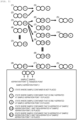
- FIG. 3 is a diagram illustrating a position and information of the sample container 102 immediately before the sample container 102 is transferred from the sample transfer point 104 to the sample aspiration point 109.
- any one state of (1) to (4) in FIG. 3 is obtained.
- (3) and (4) may be regarded as the same because the order of measurement can be changed depending on a type of the sample to be supplied later.
- (3) is in any one state of (6) to (9).
- (6) returns to the initial state of (5) at the start of the next cycle.
- (7) and (9) are in a state in which the sample container is placed at the sample aspiration point 2 and are a situation in which the sample container is about to be placed from the sample transfer point to the sample aspiration point 2.
- scheduling for changing a measurement order is performed.
- (9) is changed to a situation (8), and (7) is changed to (7') from the state of (4) instead of the state (3).
- (7') returns to the initial state of (5) at the start of the next cycle.
- a device can be controlled by creating four time charts of (1), (3), (6), and (8).
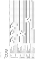
- FIG. 4 illustrates a time chart of the situation (1) of FIG. 3 .
- the sample transfer means is at the sample transfer point and does not grasp the sample container, the sample aspiration mechanism and the waste liquid aspiration mechanism are at a washing position, and the transfer mechanism is in a device unit in a state of holding the sample container.
- the sample transfer means grasps the sample container at the sample transfer point at 1 s and moves to the sample aspiration point 1 at 3 s.
- the sample container is installed at 4 s and then moved to the waste liquid aspiration point.
- the sample aspiration mechanism 106 during washing accesses the sample aspiration point at 7 s, aspirates the sample at 8 s, and introduces the sample into the analysis unit at 10 s. After the introduction, a washing operation is performed. Meanwhile, the sample transfer means moves to the waste liquid aspiration point at 6 s, grasps the sample container used in a previous cycle at 7 s, and installs the sample container at the sample transfer point at 10 s.
- the transfer mechanism moves the received sample container to the pretreatment unit and discards the sample container in the pretreatment unit.
- the sample transfer means moves to the sample aspiration point 1 at 12 s, grasps the sample container used for the measurement, and moves the sample container to the waste liquid aspiration point. Further, the waste liquid aspiration mechanism aspirates a
- FIG. 5 illustrates a time chart of the situation (3) of FIG. 3 .
- the sample container is transferred to the waste liquid aspiration point after the measurement is completed, and in this situation, the sample container is moved to the sample aspiration point 2.
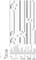
- FIG. 6 illustrates a time chart of the situation (6) of FIG. 3 .
- the sample container is placed at the sample aspiration point 2.
- the sample container at the sample transfer point is installed at the sample aspiration point 1.
- the sample container at the sample aspiration point 2 is transferred to the waste liquid aspiration point, the sample transfer point, and the pretreatment unit.
- the sample container at the sample aspiration point 1 is transferred to the waste liquid aspiration point, the sample transfer point, and the pretreatment unit.
- the pretreatment unit can additionally discard the sample container.
- FIG. 7 is a time chart when there is no margin. Using the retraction point, one sample container is carried over in the next cycle.
- FIG. 8 illustrates a time chart of the situation (6) of FIG. 3 .
- the sample container at the sample aspiration point 1 is transferred to the waste liquid aspiration point after the measurement is completed, and in this situation, the sample container is moved to the sample aspiration point 2.
- the autosampler of the liquid chromatograph includes a plurality of sample aspiration nozzles that aspirate a sample from sample containers installed at respective sample aspiration points; a sample transfer means (gripper) that transfers the sample containers to the respective sample aspiration points; and a retraction point where the sample container (received from the sample pretreatment unit) put into the autosampler and the sample container collected from the sample aspiration point are held.
- the retraction point can be used as a place for placing a sample container until the sample container for which a test has been completed is returned to a discarding place (for example, the pretreatment unit).
- a discarding place for example, the pretreatment unit.
- the sample transfer means for moving the sample container to a delivery place with the pretreatment unit, the sample aspiration point, the waste liquid aspiration point, and the retraction point is provided, the sample can be automatically delivered to and from the pretreatment unit.
- the sample transfer means may stop the operation without the loss of the sample and confirm the situation by performing the operation of installing the sample container at the retraction point.
- the movement of the aspiration nozzle on the plane to all the positions that the aspiration nozzle accesses in one cycle can be completed by one driving element. Further, since the sample aspiration points are arranged on a straight line, an occupation area can be reduced as compared with that of arrangement of the sample aspiration point in a turn table type.
- the number of the driving elements of the sample transfer means can be reduced by one as compared with arrangement in which the driving elements are arranged in a grid pattern on the plane.
- space-saving refers to a structure in which an area to be used and the number of the driving elements are reduced by arranging the aspiration points on the straight line or by covering the places to be accessed by the aspiration nozzles with one driving element.
- prevention of throughput reduction due to a plurality of times of the measurement of one sample means that the device can be operated to prevent reduction in the throughput even when a plurality of analyses are performed in one sample container.
- a plurality of analyses are performed on one sample container, that is, when it is necessary to install the sample container in order at a plurality of sample aspiration points to perform the aspiration, a place for the sample container that is no longer placed is provided.
- mplification of a structure refers to a structure in which the number of motors is reduced by arranging the aspiration points on the straight line and by covering the places to be accessed by the aspiration nozzles with one driving element.
- prevention of the loss of the sample means that the operation can be stopped without the loss of the sample and the situation can be confirmed when the device cannot be confirmed whether the sample transfer means holds the sample container, for example, the device stops due to an error.
- the autosampler 101 of the liquid chromatograph is used in the example, the invention is also applicable to an automatic analyzer or an analyzer for DNA and the like.
Landscapes
- Physics & Mathematics (AREA)
- Health & Medical Sciences (AREA)
- Life Sciences & Earth Sciences (AREA)
- Chemical & Material Sciences (AREA)
- Analytical Chemistry (AREA)
- Biochemistry (AREA)
- General Health & Medical Sciences (AREA)
- General Physics & Mathematics (AREA)
- Immunology (AREA)
- Pathology (AREA)
- Automatic Analysis And Handling Materials Therefor (AREA)
Abstract
Description
- The present invention relates to an autosampler of a liquid chromatograph and a liquid chromatograph including the same.
- A general autosampler (automatic sample injection device) of a liquid chromatograph aspirates a sample received from a pretreatment unit (device or person) with an aspiration nozzle, injects the sample into an injection port of an injection valve, and introduces the sample into a flow path system including a column. After the introduction of the sample, in order to reduce a carry-over, a needle, the injection valve, the injection port, and a flow path tube are thoroughly washed.
-
PTL 1 describes an autosampler of a liquid chromatograph, and discloses that "an automatic sampling and reaction system has a microreactor in fluidic communication with an external sampling valve. The external sampling valve is connected to a priming valve and can draw a sample from a reactor or a reactor stream. The microreactor is connected to a reagent valve and an injection valve. The reagent valve can draw a reagent from a reagent reservoir and discharge the reagent to the microreactor to react with the sample. The priming valve can draw a washing agent from a washing agent reservoir and discharge the washing agent to the external sampling valve to move the sample from the external sampling valve to the microreactor. The injection valve is in fluidic communication with a column or a detector and discharges a secondary sample into a solvent composition stream" (see abstract). - PTL 1:
JP2016-126019A - In a case where a throughput of a pretreatment unit exceeds a throughput of an autosampler, a sample container is congested between the pretreatment unit and the autosampler. PTL 1 has not studied a countermeasure against such a case.
- An object of the invention is to provide an autosampler of a liquid chromatograph capable of managing a sample container even in a case where the throughput of the pretreatment unit exceeds the throughput of the autosampler.
- In order to solve the above problem, for example, a configuration described in claims is adopted.
- The present application includes a plurality of means for solving the above problem, and an example thereof is an autosampler of a liquid chromatograph, including: a plurality of injection valves; and sample aspiration nozzles that are connected to respective injection ports of the plurality of injection valves and that aspirate a sample from sample containers installed at respective sample aspiration points; a sample transfer means that transfers the sample containers to the respective sample aspiration points; and a retraction point where the sample container put into the autosampler and the sample container collected from the sample aspiration points can be held.
- According to the invention, an autosampler of a liquid chromatograph capable of managing a sample container even in a case where a throughput of a pretreatment unit exceeds a throughput of an autosampler can be provided.
- Problems, configurations, and effects other than those described above will be clarified by the following description of an example.
-
- [
FIG. 1] FIG. 1 is a plan view of an autosampler of a liquid chromatograph according to an example. - [
FIG. 2] FIG. 2 is a schematic diagram illustrating a driving range of a sample aspiration mechanism and a washing tank. - [
FIG. 3] FIG. 3 is a diagram illustrating a sample supply pattern when there are two sample aspiration points. - [
FIG. 4] FIG. 4 is a time chart of the situation (1) ofFIG. 3 . - [
FIG. 5] FIG. 5 is a time chart of the situation (3) ofFIG. 3 . - [
FIG. 6] FIG. 6 is a time chart of the situation (6) ofFIG. 3 . - [
FIG. 7] FIG. 7 is a time chart when only one sample container can be discarded in one cycle in the situation (6) ofFIG. 3 . - [
FIG. 8] FIG. 8 is a time chart of the situation (8) ofFIG. 3 . - Hereinafter, an example will be described with reference to the drawings.
- A device configuration of the invention will be described with reference to
FIG. 1. FIG. 1 is a schematic view of anautosampler 101 of a liquid chromatograph according to an example. Theautosampler 101 includes asample container 102, atransfer mechanism 103, asample transfer point 104, a sample transfer means 105, asample aspiration mechanism 106, asample aspiration nozzle 107, awashing tank 108, asample aspiration point 109, a wasteliquid aspiration mechanism 110, a wasteliquid aspiration point 111, and aretraction point 112. - The
sample container 102 is a container that holds an object to be measured represented by a sample alone or a mixture of a sample and a reagent. - The
transfer mechanism 103 is a mechanism that introduces thesample container 102 from a pretreatment unit to theautosampler 101. - The
sample transfer point 104 is a position in which thesample container 102 is held, and is a place in which thesample container 102 is placed when introduced into theautosampler 101 from the pretreatment unit. In the present example, thesample transfer point 104 is installed in thetransfer mechanism 103. Therefore, it is possible to introduce thesample container 102 into theautosampler 101 by installing thesample container 102 containing a pretreated sample at thesample transfer point 104 and introducing thetransfer mechanism 103 into theautosampler 101. - The
transfer mechanism 103 and thesample transfer point 104 do not necessarily have to be formed as described above. For example, thesample container 102 may be provided at thesample transfer point 104 installed in theautosampler 101 using a human hand as thetransfer mechanism 103. - The sample transfer means 105 is a mechanism that transfers the
sample container 102 to another place. In the present example, a mechanism for gripping thesample container 102 is used, and a mechanism for pushing or pulling thesample container 102 out or in by an arm, a hook, or the like, or a non-contact sample transfer means using electromagnetic force or the like may be used. - The
sample aspiration mechanism 106 is a mechanism that aspirates the sample in thesample container 102 using thesample aspiration nozzle 107 and transfers the sample to an analysis unit such as a column or a photometer. - The
washing tank 108 is a mechanism for mainly washing an outer wall of thesample aspiration nozzle 107 before sample aspiration or in contact with the sample, and also has a function of discharging a waste liquid passed through thesample aspiration nozzle 107 to make an internal state of thesample aspiration nozzle 107 the same in each measurement or to wash inside of thesample aspiration nozzle 107. The mechanism will be described in detail with reference toFIG. 2 . - The
sample aspiration point 109 is a position for holding thesample container 102 and aspirating the sample by thesample aspiration mechanism 106. - The waste
liquid aspiration mechanism 110 is a mechanism for aspirating and discarding the sample in the sample container. - The waste
liquid aspiration point 111 is a position for holding thesample container 102 and aspirating the sample by the wasteliquid aspiration mechanism 110. - The
retraction point 112 is a position for holding thesample container 102 and receiving thesample container 102 that is no longer placed due to, for example, aspirating the sample in onesample container 102 by the plurality ofsample aspiration mechanisms 106. When theautosampler 101 cannot confirm whether the sample transfer means 105 holds thesample container 102, for example, theautosampler 101 stops due to an error, loss of the sample can be prevented by installing thesample container 102 at theretraction point 112. - A driving range of the
sample aspiration mechanism 106 and thewashing tank 108 will be described in detail with reference toFIG. 2. FIG. 2 is a schematic view focusing on thesample aspiration mechanism 106 and thewashing tank 108.FIG. 2 includes anoutside washing point 201 and a wasteliquid discharge point 202. - The
outside washing point 201 is a mechanism for mainly washing the outer wall of thesample aspiration nozzle 107 before the sample aspiration or in contact with the sample. In the present example, a washing point of a type in which the washing liquid flows out from below is used, and the washing liquid may be discharged to the sample aspiration nozzle. When a plurality of types of washing liquids are used, the number of theoutside washing points 201 may be increased. The wasteliquid discharge point 202 is a mechanism that discharges the waste liquid passed through thesample aspiration nozzle 107 to make the internal state of thesample aspiration nozzle 107 the same in each measurement or to wash the inside of thesample aspiration nozzle 107, and is connected to a waste liquid flow path. Thesample aspiration nozzle 107 can rotate around arotation center 203 of the sample aspiration nozzle. By arranging thesample aspiration point 109, theoutside washing point 201, and the wasteliquid discharge point 202 on atrajectory 204 of the sample aspiration nozzle, movement of thesample aspiration nozzle 107 on a plane to all positions that thesample aspiration nozzle 107 accesses in one cycle can be completed by one driving element provided in thesample aspiration mechanism 106. - A process of the invention will be described with reference to
FIG. 1 . - The
sample container 102 is introduced into theautosampler 101 from the pretreatment unit using thetransfer mechanism 103. Thesample container 102 placed at thesample transfer point 104 is installed at thesample aspiration point 109 using the sample transfer means 105. After thesample aspiration nozzle 107 is washed in thewashing tank 108, the sample is introduced from thesample container 102 at thesample aspiration point 109 into the analysis unit such as the column or the photometer through thesample aspiration nozzle 107. Thesample container 102 is transferred to the wasteliquid aspiration point 111 by the sample transfer means 105, and the waste liquid aspiration mechanism aspirates the sample in the sample container. Thesample container 102 is transferred again to thesample transfer point 104 by the sample transfer means 105 and returned to the pretreatment unit by thetransfer mechanism 103. - A sample supply pattern when there are two sample aspiration points will be described with reference to
FIG. 3. FIG. 3 is a diagram illustrating a position and information of thesample container 102 immediately before thesample container 102 is transferred from thesample transfer point 104 to thesample aspiration point 109. - At the start of the measurement, since there is no sample at the sample aspiration point, any one state of (1) to (4) in
FIG. 3 is obtained. However, (3) and (4) may be regarded as the same because the order of measurement can be changed depending on a type of the sample to be supplied later. (1) and (2) return to an initial state of (5) = (1) to (4) at the start of a next cycle. (3) is in any one state of (6) to (9). (6) returns to the initial state of (5) at the start of the next cycle. (8) returns to the state of (10) = (6) to (9) at the start of the next cycle. (7) and (9) are in a state in which the sample container is placed at thesample aspiration point 2 and are a situation in which the sample container is about to be placed from the sample transfer point to thesample aspiration point 2. In order to avoid such a situation, when an interference occurs in an installation place at which "2" or "2-1" is placed next to the sample container of "1-2", scheduling for changing a measurement order is performed. Specifically, (9) is changed to a situation (8), and (7) is changed to (7') from the state of (4) instead of the state (3). (7') returns to the initial state of (5) at the start of the next cycle. As described above, a device can be controlled by creating four time charts of (1), (3), (6), and (8). -
FIG. 4 illustrates a time chart of the situation (1) ofFIG. 3 . In the initial state, the sample transfer means is at the sample transfer point and does not grasp the sample container, the sample aspiration mechanism and the waste liquid aspiration mechanism are at a washing position, and the transfer mechanism is in a device unit in a state of holding the sample container. - The sample transfer means grasps the sample container at the sample transfer point at 1 s and moves to the
sample aspiration point 1 at 3 s. The sample container is installed at 4 s and then moved to the waste liquid aspiration point. Thesample aspiration mechanism 106 during washing accesses the sample aspiration point at 7 s, aspirates the sample at 8 s, and introduces the sample into the analysis unit at 10 s. After the introduction, a washing operation is performed. Meanwhile, the sample transfer means moves to the waste liquid aspiration point at 6 s, grasps the sample container used in a previous cycle at 7 s, and installs the sample container at the sample transfer point at 10 s. The transfer mechanism moves the received sample container to the pretreatment unit and discards the sample container in the pretreatment unit. The sample transfer means moves to thesample aspiration point 1 at 12 s, grasps the sample container used for the measurement, and moves the sample container to the waste liquid aspiration point. Further, the waste liquid aspiration mechanism aspirates a residual liquid at 19 s. -
FIG. 5 illustrates a time chart of the situation (3) ofFIG. 3 . InFIG. 4 , the sample container is transferred to the waste liquid aspiration point after the measurement is completed, and in this situation, the sample container is moved to thesample aspiration point 2. -
FIG. 6 illustrates a time chart of the situation (6) ofFIG. 3 . In the initial state, the sample container is placed at thesample aspiration point 2. In this situation, the sample container at the sample transfer point is installed at thesample aspiration point 1. After aspirating the sample, first, the sample container at thesample aspiration point 2 is transferred to the waste liquid aspiration point, the sample transfer point, and the pretreatment unit. Next, the sample container at thesample aspiration point 1 is transferred to the waste liquid aspiration point, the sample transfer point, and the pretreatment unit. In this case, the pretreatment unit can additionally discard the sample container.FIG. 7 is a time chart when there is no margin. Using the retraction point, one sample container is carried over in the next cycle. -
FIG. 8 illustrates a time chart of the situation (6) ofFIG. 3 . InFIG. 6 , the sample container at thesample aspiration point 1 is transferred to the waste liquid aspiration point after the measurement is completed, and in this situation, the sample container is moved to thesample aspiration point 2. - The autosampler of the liquid chromatograph according to the present example includes a plurality of sample aspiration nozzles that aspirate a sample from sample containers installed at respective sample aspiration points; a sample transfer means (gripper) that transfers the sample containers to the respective sample aspiration points; and a retraction point where the sample container (received from the sample pretreatment unit) put into the autosampler and the sample container collected from the sample aspiration point are held. According to the present example, for example, when one sample is aspirated at a plurality of sample aspiration points to perform the measurement a plurality of times, the retraction point can be used as a place for placing a sample container until the sample container for which a test has been completed is returned to a discarding place (for example, the pretreatment unit). When it is impossible to confirm whether the sample transfer means holds the sample container, for example, at the time of occurrence of an error, it is possible to stop an operation without the loss of the sample and confirm the situation by performing an operation of installing the sample container at the retraction point.
- Since the sample transfer means for moving the sample container to a delivery place with the pretreatment unit, the sample aspiration point, the waste liquid aspiration point, and the retraction point is provided, the sample can be automatically delivered to and from the pretreatment unit.
- When the retraction point is used as the place for placing the sample container until the sample container for which the test has been completed is returned to the discarding place (for example, the pretreatment unit), and the device cannot confirm whether the sample transfer means holds the sample container, for example, the device stops due to the error, the sample transfer means may stop the operation without the loss of the sample and confirm the situation by performing the operation of installing the sample container at the retraction point.
- The movement of the aspiration nozzle on the plane to all the positions that the aspiration nozzle accesses in one cycle can be completed by one driving element. Further, since the sample aspiration points are arranged on a straight line, an occupation area can be reduced as compared with that of arrangement of the sample aspiration point in a turn table type. The number of the driving elements of the sample transfer means can be reduced by one as compared with arrangement in which the driving elements are arranged in a grid pattern on the plane.
- According to the invention, it is possible to satisfy "space-saving" in relation to a device area, "acceptance of throughput improvement of the pretreatment unit" and "prevention of throughput reduction due to a plurality of times of the measurement of one sample" in relation to a throughput performance, and "simplification of a structure" and "prevention of the loss of the sample" in relation to robustness.
- The term "space-saving" mentioned herein refers to a structure in which an area to be used and the number of the driving elements are reduced by arranging the aspiration points on the straight line or by covering the places to be accessed by the aspiration nozzles with one driving element.
- The term "prevention of throughput reduction due to a plurality of times of the measurement of one sample" mentioned herein means that the device can be operated to prevent reduction in the throughput even when a plurality of analyses are performed in one sample container. When a plurality of analyses are performed on one sample container, that is, when it is necessary to install the sample container in order at a plurality of sample aspiration points to perform the aspiration, a place for the sample container that is no longer placed is provided.
- The term "simplification of a structure" mentioned herein refers to a structure in which the number of motors is reduced by arranging the aspiration points on the straight line and by covering the places to be accessed by the aspiration nozzles with one driving element.
- The term "prevention of the loss of the sample" mentioned herein means that the operation can be stopped without the loss of the sample and the situation can be confirmed when the device cannot be confirmed whether the sample transfer means holds the sample container, for example, the device stops due to an error.
- The
autosampler 101 of the liquid chromatograph is used in the example, the invention is also applicable to an automatic analyzer or an analyzer for DNA and the like. - Further, the invention is not limited to the above example, and includes various modifications. For example, the above example has been described in detail for easy understanding of the invention, and the invention is not necessarily limited to those including all configurations described above.
-
- 101:
- autosampler
- 102:
- sample container
- 103:
- transfer mechanism
- 104:
- sample transfer point
- 105:
- sample transfer means
- 106:
- sample aspiration mechanism
- 107:
- sample aspiration nozzle
- 108:
- washing tank
- 109:
- sample aspiration point
- 110:
- waste liquid aspiration mechanism
- 111:
- waste liquid aspiration point
- 112:
- retraction point
- 201:
- outside washing point
- 202:
- waste liquid discharge point
- 203:
- rotation center of sample aspiration nozzle
- 204:
- trajectory of sample aspiration nozzle
Claims (4)
- An autosampler of a liquid chromatograph comprising:a plurality of sample aspiration nozzles configured to aspirate a sample from sample containers installed at respective sample aspiration points;a sample transfer means configured to transfer the sample containers to the respective sample aspiration points; anda retraction point where the sample container put into the autosampler and the sample container collected from the sample aspiration point can be held.
- The autosampler of a liquid chromatograph according to claim 1,
wherein the sample aspiration point and a washing point are arranged at a position accessible by moving one driving element. - The autosampler of a liquid chromatograph according to claim 2,
wherein the sample aspiration points are arranged on a straight line. - A liquid chromatograph comprising:
the autosampler of liquid chromatograph according to any one of claims 1 to 3.
Applications Claiming Priority (2)
| Application Number | Priority Date | Filing Date | Title |
|---|---|---|---|
| JP2020208191 | 2020-12-16 | ||
| PCT/JP2021/045055 WO2022131091A1 (en) | 2020-12-16 | 2021-12-08 | Liquid chromatograph autosampler and liquid chromatograph comprising same |
Publications (2)
| Publication Number | Publication Date |
|---|---|
| EP4266060A1 true EP4266060A1 (en) | 2023-10-25 |
| EP4266060A4 EP4266060A4 (en) | 2024-11-27 |
Family
ID=82057758
Family Applications (1)
| Application Number | Title | Priority Date | Filing Date |
|---|---|---|---|
| EP21906454.0A Pending EP4266060A4 (en) | 2020-12-16 | 2021-12-08 | AUTOMATIC SAMPLE COLLECTOR FOR A LIQUID CHROMATOGRAPH AND LIQUID CHROMATOGRAPH THEREOF |
Country Status (5)
| Country | Link |
|---|---|
| US (1) | US12523635B2 (en) |
| EP (1) | EP4266060A4 (en) |
| JP (1) | JP7576102B2 (en) |
| CN (1) | CN116472462A (en) |
| WO (1) | WO2022131091A1 (en) |
Family Cites Families (13)
| Publication number | Priority date | Publication date | Assignee | Title |
|---|---|---|---|---|
| JPH08313538A (en) * | 1995-05-22 | 1996-11-29 | Mitsubishi Corp | Automatic analyzer |
| JP2009042226A (en) * | 2007-07-18 | 2009-02-26 | Hitachi High-Technologies Corp | Capillary electrophoresis apparatus and sample tray |
| JP4985851B2 (en) * | 2008-08-19 | 2012-07-25 | 株式会社島津製作所 | Preparative liquid chromatograph |
| US9442128B2 (en) * | 2011-10-18 | 2016-09-13 | Hitachi High-Technologies Corporation | Automated analyzer |
| JP5978039B2 (en) * | 2012-07-24 | 2016-08-24 | 株式会社日立ハイテクノロジーズ | Automatic analyzer |
| JP5993737B2 (en) * | 2012-12-17 | 2016-09-14 | 株式会社日立ハイテクノロジーズ | Automatic analyzer |
| JP6173883B2 (en) * | 2013-10-31 | 2017-08-02 | シスメックス株式会社 | Sample container extraction device and sample processing system |
| US9857339B2 (en) | 2015-01-06 | 2018-01-02 | Waters Technologies Corporation | Automated sampling and reaction system for high pressure liquid chromatography and other types of detection |
| JP6418017B2 (en) | 2015-03-13 | 2018-11-07 | 株式会社島津製作所 | Pre-processing apparatus and analysis system provided with the same |
| US10184104B2 (en) * | 2015-11-19 | 2019-01-22 | Alexander Lee Lianides | Automated system for cultivating transgenic C. elegans |
| JP6689597B2 (en) | 2015-11-27 | 2020-04-28 | シスメックス株式会社 | Blood coagulation analyzer |
| CN112805571B (en) * | 2018-11-02 | 2024-07-12 | 株式会社岛津制作所 | Sample pretreatment device, analysis system including the device and automatic sampler |
| CN113711054B (en) | 2019-04-26 | 2024-12-13 | 株式会社日立高新技术 | Automatic analysis device |
-
2021
- 2021-12-08 JP JP2022569903A patent/JP7576102B2/en active Active
- 2021-12-08 US US18/253,987 patent/US12523635B2/en active Active
- 2021-12-08 EP EP21906454.0A patent/EP4266060A4/en active Pending
- 2021-12-08 CN CN202180078626.2A patent/CN116472462A/en active Pending
- 2021-12-08 WO PCT/JP2021/045055 patent/WO2022131091A1/en not_active Ceased
Also Published As
| Publication number | Publication date |
|---|---|
| EP4266060A4 (en) | 2024-11-27 |
| WO2022131091A1 (en) | 2022-06-23 |
| US12523635B2 (en) | 2026-01-13 |
| JPWO2022131091A1 (en) | 2022-06-23 |
| CN116472462A (en) | 2023-07-21 |
| JP7576102B2 (en) | 2024-10-30 |
| US20230408459A1 (en) | 2023-12-21 |
Similar Documents
| Publication | Publication Date | Title |
|---|---|---|
| US5876668A (en) | Automatic biochemical analyzer | |
| JP5437115B2 (en) | Probe cleaning method in clinical test equipment | |
| CN103890589B (en) | Automatic analysis device | |
| EP2672274A1 (en) | Automatic analyzing device | |
| JP6585134B2 (en) | Automatic analyzer | |
| US11360112B2 (en) | Automatic analyzer | |
| CA2392943A1 (en) | Chemistry system for a clinical analyzer | |
| JPS633265A (en) | Automatic chemical analyzer | |
| EP1536237A2 (en) | Automatic analyzer | |
| EP3974837A1 (en) | Automatic analysis device | |
| EP3961223A1 (en) | Automatic analysis device | |
| EP3971583B1 (en) | Automatic analyzing device | |
| JP2011033426A (en) | Automatic analyzer and method of controlling the same | |
| US12523635B2 (en) | Autosampler of liquid chromatograph and liquid chromatograph including the same | |
| WO1998014785A1 (en) | Aliquoting method for automatic sample examination and measurement instrument | |
| US20210025910A1 (en) | Probe Washing Arrangement With Multiple Configurations For Sample Analyzer And Method Of Using | |
| USRE39600E1 (en) | Liquid sample dispensing methods for precisely delivering liquids without crossover | |
| EP4239341A1 (en) | Automatic analysis device | |
| EP4403927A1 (en) | Method and device for purifying fluids in a container | |
| EP4592684A1 (en) | Sample analyzer | |
| KR810001437B1 (en) | Sampling device | |
| JPH04131765A (en) | Delay time control device for biochemical automatic analysis | |
| JPH0616052B2 (en) | Reagent dispenser | |
| JPS61240165A (en) | Multi-item analytical method and apparatus | |
| JPS60127463A (en) | Liquid distribution apparatus |
Legal Events
| Date | Code | Title | Description |
|---|---|---|---|
| STAA | Information on the status of an ep patent application or granted ep patent |
Free format text: STATUS: THE INTERNATIONAL PUBLICATION HAS BEEN MADE |
|
| PUAI | Public reference made under article 153(3) epc to a published international application that has entered the european phase |
Free format text: ORIGINAL CODE: 0009012 |
|
| STAA | Information on the status of an ep patent application or granted ep patent |
Free format text: STATUS: REQUEST FOR EXAMINATION WAS MADE |
|
| 17P | Request for examination filed |
Effective date: 20230519 |
|
| AK | Designated contracting states |
Kind code of ref document: A1 Designated state(s): AL AT BE BG CH CY CZ DE DK EE ES FI FR GB GR HR HU IE IS IT LI LT LU LV MC MK MT NL NO PL PT RO RS SE SI SK SM TR |
|
| DAV | Request for validation of the european patent (deleted) | ||
| DAX | Request for extension of the european patent (deleted) | ||
| A4 | Supplementary search report drawn up and despatched |
Effective date: 20241025 |
|
| RIC1 | Information provided on ipc code assigned before grant |
Ipc: G01N 30/86 20060101ALI20241021BHEP Ipc: G01N 30/24 20060101ALI20241021BHEP Ipc: G01N 35/02 20060101AFI20241021BHEP |
|
| STAA | Information on the status of an ep patent application or granted ep patent |
Free format text: STATUS: EXAMINATION IS IN PROGRESS |
|
| 17Q | First examination report despatched |
Effective date: 20260216 |